SUPER SHOT 60 MELTERPART MANUAL - 26616
REV. B

2
Revised: 04/2014

3
SUPER SHOT 60 MELTER
4
TABLE OF CONTENTS
Super Shot 60 Melter.......................................................................................................... 5Safety Precautions.............................................................................................................. 6-7Limited Warranty.................................................................................................................. 8Warranty Claim Instructions................................................................................................ 9Contact Us........................................................................................................................... 10Specifications...................................................................................................................... 11Introduction........................................................................................................................... 12
Operating InstructionsMachine Start Up...........................................................................................13-14Dispensing the Material............................................................................... 15Active Pump Protection/Loading the Machine.......................................... 16Shutdown and Clean-Out Procedure/Storing Machine............................. 17Electric Hose Care and Cautions............................................................... 18Hose Transport Instructions......................................................................... 19
MaintenanceMaintenance Instructions............................................................................. 20Maintenance Chart/Service Instructions.................................................... 21Recommended Fluids and Lubricants...................................................... 22Typical Specifications................................................................................. 23Super Shot Pump Replacement ............................................................... 24Super Shot Pump Replacement Diagram............................................... 25
Trouble ShootingHose Does Not Heat................................................................................... 26-28Material Does Not Dispense When Pump is Activated.......................... 28-30Pump Rotates But No Material is Discharged......................................... 30Material Dispensing Rate is Too Slow...................................................... 30RTD Sensor-OHMS vs. Temperature........................................................ 31Burner Schematic........................................................................................ 32Burner Trouble Shooting............................................................................. 33Trouble Shooting Hydraulics...................................................................... 34Hydraulic Schematic Diagram.................................................................. 35
PartsSuper Shot 60 Melter Assembly Diagram and Parts.............................. 36-39Tank Detail Diagram and Parts................................................................. 40-41Control Box Assembly Diagram and Parts.............................................. 42-43Gas Manifold Assembly Diagram and Parts............................................ 44-45Power-Pack Assembly Diagram and Parts............................................. 46-47Hydraulic Valve Assembly.......................................................................... 48Pump/Agitator Assembly............................................................................ 49Burner Assembly......................................................................................... 50-51Hydraulic Diagram and Parts.................................................................... 52-53LPG Schematic and Parts........................................................................ 54-55Electrical Schematic and Parts................................................................. 56-57Optional Shot Timer Electrical Schematic ............................................... 58
5
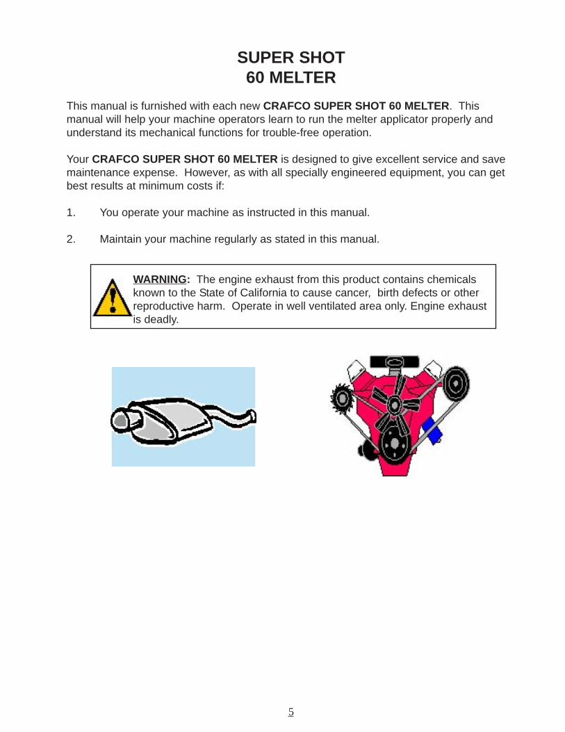
SUPER SHOT60 MELTER
This manual is furnished with each new CRAFCO SUPER SHOT 60 MELTER. Thismanual will help your machine operators learn to run the melter applicator properly andunderstand its mechanical functions for trouble-free operation.
Your CRAFCO SUPER SHOT 60 MELTER is designed to give excellent service and savemaintenance expense. However, as with all specially engineered equipment, you can getbest results at minimum costs if:
1. You operate your machine as instructed in this manual.
2. Maintain your machine regularly as stated in this manual.
WARNING: The engine exhaust from this product contains chemicalsknown to the State of California to cause cancer, birth defects or otherreproductive harm. Operate in well ventilated area only. Engine exhaustis deadly.
6
SAFETY PRECAUTIONS
• High operating temperatures of sealant and machine require protective clothing, hardsoled shoes and heat resistant gloves to be worn by operator.
• Always wear eye protection.
• Observe all CAUTION AND WARNING signs posted on machine.
• Avoid the entrance of water into any part of the machine. Water will displace heat transfer oilor sealant, which could be hazardous to personnel surrounding the machine when it reachesoperating temperatures.
• Avoid bodily contact with hot sealant material or heat transfer oil, serious burns mayresult.
• Read Operator Manual thoroughly before operating machine.
• Make sure operator is familiar with machine operation.
• Do not operate in closed building or confined areas.
• Shut-down burner and engine prior to refilling diesel tank.
• When adding solid material to sealant tank, stop mixer, lift lid, place material onto lid andclose lid before restarting mixer. Hot material could splash and cause serious burns if thisprocedure is not followed.
• Keep hands, feet, and clothing away from all moving parts.
• Always keep a fire extinguisher near the unit. Maintain extinguisher properly and befamiliar with its use.
•DO NOT exceed 525° F for heat transfer oil temperature.
• DO NOT overfill heat transfer oil level. Expansion of oil during heat up could causeoverflow. With machine in level position, check oil each day before starting burner, add oilto top mark on dipstick if required (at 70° F). Use only recommended heat transfer oil andchange after 500 hours of operation or one year, whichever occurs first.
• Follow operating instructions for starting and shut-down of burner. Instructions aremounted on control box.
• Calibrate temperature control prior to initial operation and each 50 hours of operation.

7
SAFETY PRECAUTIONS CON’T
• Replace any hoses which show signs of wear, fraying, or splitting. Be sure all fittings andjoints are tight and leak-proof.
•Precaution is the best insurance against accidents.
•The Super Shot 60 Melter should not be left unattended with burner lit.
•Tighten all bolts and screws after every 100 hours of operation.
•Crafco, Inc. assumes no liability for an accident or injury incurred through improper use ofthe machine.
8
LIMITED WARRANTY
WARNING: Use of replacement parts other than genuine Crafco partsmay impair the safety or reliability of your equipment and nullifies anywarranty.
Crafco, Inc., through Crafco or one of its affiliated distributor, will replace for the original pur-chaser free of charge any parts found upon examination by the factory at Chandler, Arizona, tobe defective in material or workmanship. This warranty is for a period one year from in-servicedate, but excludes engine or components, tires, and battery as these items are subject towarranties issued by their manufacturers.
Crafco, Inc. shall not be liable for parts that have been damaged by accident, alteration, abuse,improper lubrication/maintenance, normal wear, or other cause beyond our control.
The warranty provided herein extends only to the repair and/or replacement of those compo-nents on the equipment covered above and does not cover labor costs. The warranty does notextend to incidental or consequential damages incurred as a result of any defect covered bythis warranty.
All transportation and labor costs incurred by the purchaser in submitting or repairing coveredcomponents must be borne by the purchaser. Crafco, Inc. specifically disavows any otherrepresentation, warranty, or liability related to the condition or use of the product.
9
WARRANTY CLAIM INSTRUCTIONS
Crafco, Inc., warrants parts and machinery purchased through Crafco or one of its affiliateddistributors for one year from purchased or in-service date **. If parts fail to function within thefirst year of purchase, a return authorization number (RA) must be obtained. If the part waspurchased through Crafco, Inc., please contact the Crafco returns department [email protected] for a RA number or if purchased through a Crafco distributor pleasecontact your distributor. Note: if the part has a serial number associated with it, for example; amachine or electric hose or wand, this must be furnished when requesting the RA number. Thecustomer will be emailed or faxed a RA form with all instructions to return the item to Crafco,Inc. See example. If the part is found to be within the one year warranty period and has notbeen abused or modified, a credit will be issued to the customer’s account or credit card. Thecustomer may request the part be replaced instead of a credit, if desired.
** Wear items are not covered under Crafco, Inc. limited warranty. A wear item is defined asbut not limited to: material pumps, sealing tips, tires, etc.Note: All engine warranties are covered through the engine manufacture. If you need informa-tion for a distributor in your area please contact us and we will direct you to the closest enginedistributor.
**** All parts returned are tested and evaluated. If the part has been modified in anyway withoutprior consent from Crafco, Inc. representative, warranty is void.
Please follow the instructions stated below when calling in a Warranty Claim. Failure to followthese procedures may be cause to void the warranty.
1. Call your local Crafco Distributor. If you do not know who your local distributor is, call aCrafco Customer Service Representative, (Toll Free 1-800-528-8242) for name, loca-tion, and telephone number.
2. On contacting the distributor, be prepared to identify the serial number, model number,engine model, engine manufacturer, and the date of purchase if available.
3. Should the cause of the malfunction be a defective part, the Distributor will advise youof the procedure to follow for a replacement.
4. The warranty is valid only for parts, which have been supplied or recommended byCrafco, Inc.
If you have any additional questions regarding warranty repairs and parts, please do nothesitate to call toll free 1-800-528-8242.
10
CONTACT US
For Warranty:Crafco, Inc.25527 South Arizona Avenue, Chandler, AZ 85248Phone: (480) 655-8333 or (800) 528-8242Fax: (480) 655-1712
For all other inquiries:Crafco, Inc.420 North Roosevelt Avenue, Chandler, AZ 85226Phone: (602) 276-0406 or (800) 528-8242Fax: (480) [email protected]
11
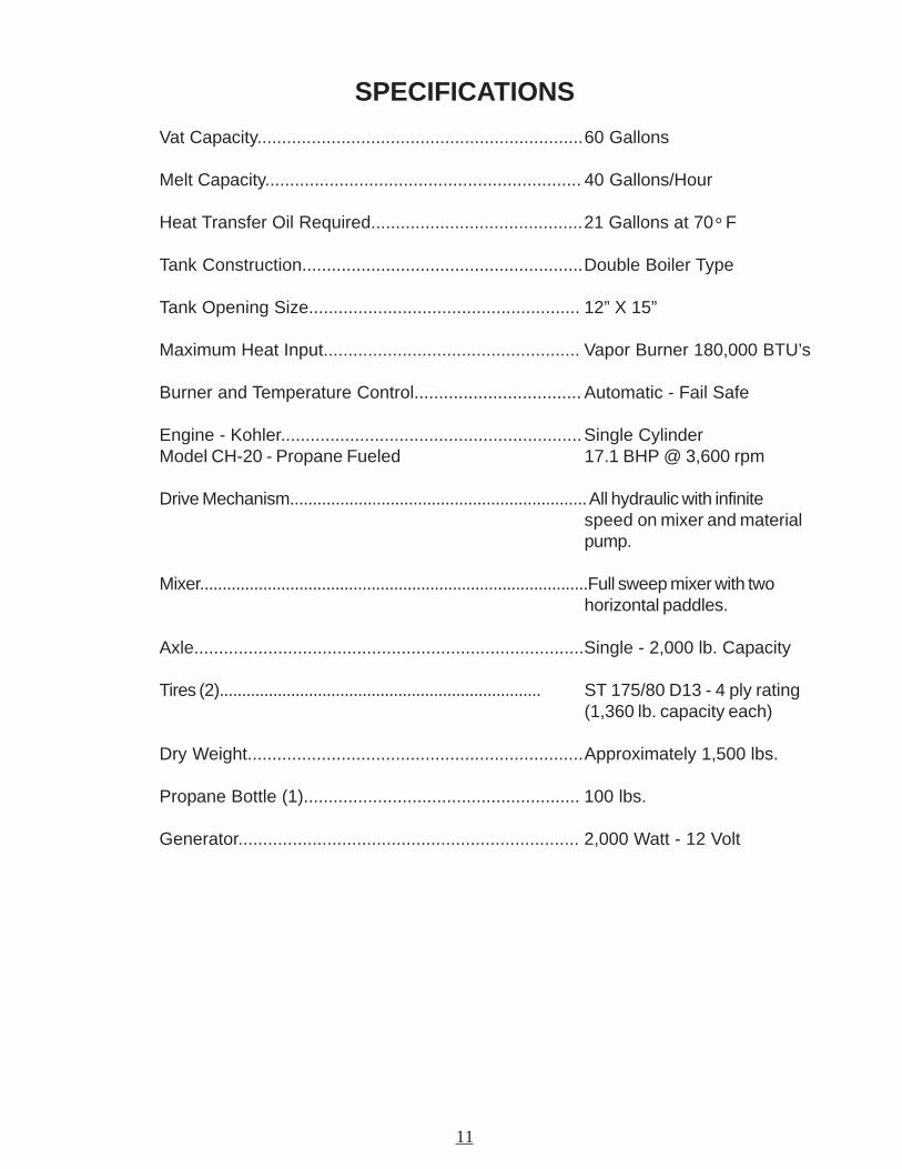
SPECIFICATIONS
Vat Capacity..................................................................60 Gallons
Melt Capacity................................................................ 40 Gallons/Hour
Heat Transfer Oil Required...........................................21 Gallons at 70° F
Tank Construction.........................................................Double Boiler Type
Tank Opening Size....................................................... 12” X 15”
Maximum Heat Input.................................................... Vapor Burner 180,000 BTU’s
Burner and Temperature Control.................................. Automatic - Fail Safe
Engine - Kohler.............................................................Single CylinderModel CH-20 - Propane Fueled 17.1 BHP @ 3,600 rpm
Drive Mechanism................................................................. All hydraulic with infinitespeed on mixer and materialpump.
Mixer......................................................................................Full sweep mixer with twohorizontal paddles.
Axle...............................................................................Single - 2,000 lb. Capacity
Tires (2)........................................................................ ST 175/80 D13 - 4 ply rating(1,360 lb. capacity each)
Dry Weight....................................................................Approximately 1,500 lbs.
Propane Bottle (1)........................................................ 100 lbs.
Generator..................................................................... 2,000 Watt - 12 Volt
12
SUPER SHOT 60 MELTER
INTRODUCTION
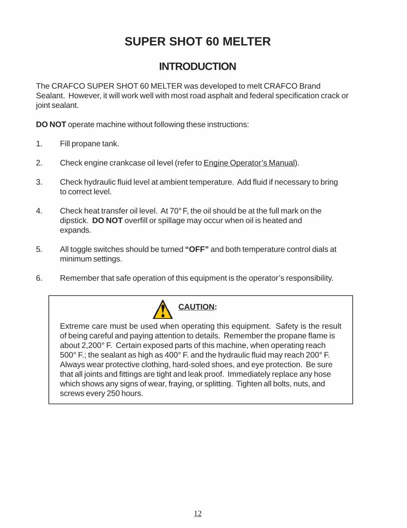
The CRAFCO SUPER SHOT 60 MELTER was developed to melt CRAFCO BrandSealant. However, it will work well with most road asphalt and federal specification crack orjoint sealant.
DO NOT operate machine without following these instructions:
1. Fill propane tank.
2. Check engine crankcase oil level (refer to Engine Operator’s Manual).
3. Check hydraulic fluid level at ambient temperature. Add fluid if necessary to bringto correct level.
4. Check heat transfer oil level. At 70° F, the oil should be at the full mark on thedipstick. DO NOT overfill or spillage may occur when oil is heated andexpands.
5. All toggle switches should be turned “OFF” and both temperature control dials atminimum settings.
6. Remember that safe operation of this equipment is the operator’s responsibility.
CAUTION:
Extreme care must be used when operating this equipment. Safety is the resultof being careful and paying attention to details. Remember the propane flame isabout 2,200° F. Certain exposed parts of this machine, when operating reach500° F.; the sealant as high as 400° F. and the hydraulic fluid may reach 200° F.Always wear protective clothing, hard-soled shoes, and eye protection. Be surethat all joints and fittings are tight and leak proof. Immediately replace any hosewhich shows any signs of wear, fraying, or splitting. Tighten all bolts, nuts, andscrews every 250 hours.
13
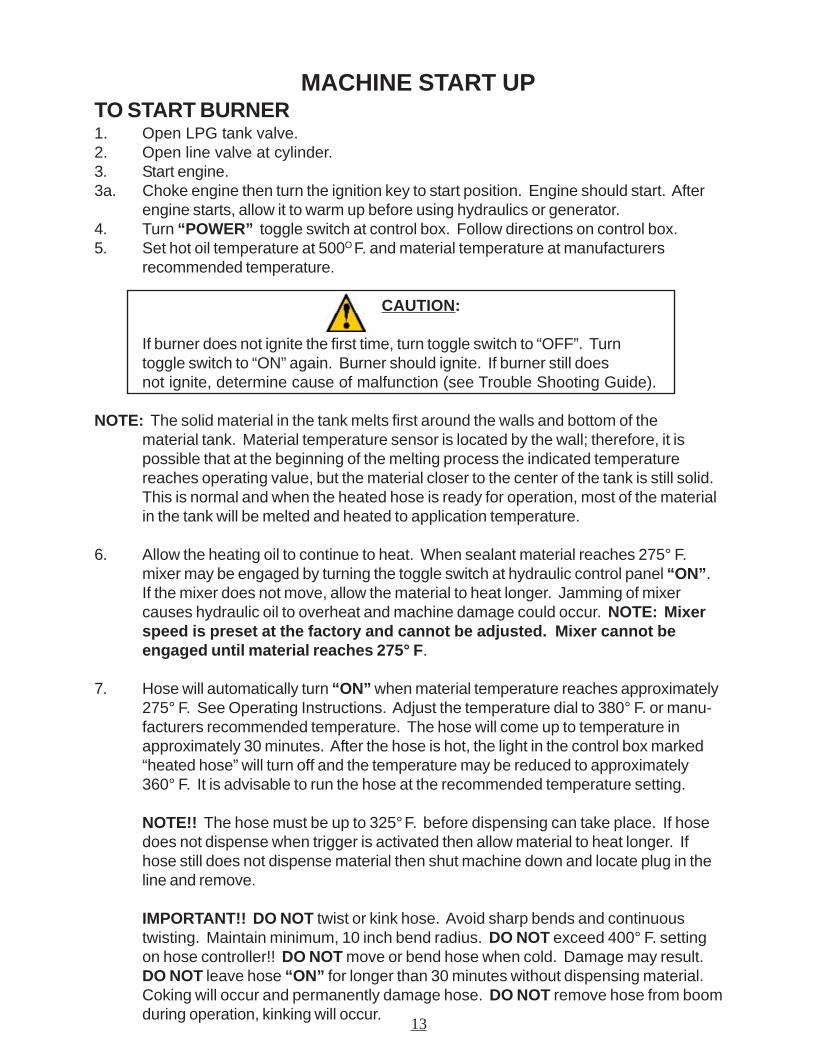
MACHINE START UPTO START BURNER1. Open LPG tank valve.2. Open line valve at cylinder.3. Start engine.3a. Choke engine then turn the ignition key to start position. Engine should start. After
engine starts, allow it to warm up before using hydraulics or generator.4. Turn “POWER” toggle switch at control box. Follow directions on control box.5. Set hot oil temperature at 500O F. and material temperature at manufacturers
recommended temperature.
CAUTION:
If burner does not ignite the first time, turn toggle switch to “OFF”. Turntoggle switch to “ON” again. Burner should ignite. If burner still doesnot ignite, determine cause of malfunction (see Trouble Shooting Guide).
NOTE: The solid material in the tank melts first around the walls and bottom of thematerial tank. Material temperature sensor is located by the wall; therefore, it ispossible that at the beginning of the melting process the indicated temperaturereaches operating value, but the material closer to the center of the tank is still solid.This is normal and when the heated hose is ready for operation, most of the materialin the tank will be melted and heated to application temperature.
6. Allow the heating oil to continue to heat. When sealant material reaches 275° F.mixer may be engaged by turning the toggle switch at hydraulic control panel “ON”.If the mixer does not move, allow the material to heat longer. Jamming of mixercauses hydraulic oil to overheat and machine damage could occur. NOTE: Mixerspeed is preset at the factory and cannot be adjusted. Mixer cannot beengaged until material reaches 275° F.
7. Hose will automatically turn “ON” when material temperature reaches approximately275° F. See Operating Instructions. Adjust the temperature dial to 380° F. or manu-facturers recommended temperature. The hose will come up to temperature inapproximately 30 minutes. After the hose is hot, the light in the control box marked“heated hose” will turn off and the temperature may be reduced to approximately360° F. It is advisable to run the hose at the recommended temperature setting.
NOTE!! The hose must be up to 325° F. before dispensing can take place. If hosedoes not dispense when trigger is activated then allow material to heat longer. Ifhose still does not dispense material then shut machine down and locate plug in theline and remove.
IMPORTANT!! DO NOT twist or kink hose. Avoid sharp bends and continuoustwisting. Maintain minimum, 10 inch bend radius. DO NOT exceed 400° F. settingon hose controller!! DO NOT move or bend hose when cold. Damage may result.DO NOT leave hose “ON” for longer than 30 minutes without dispensing material.Coking will occur and permanently damage hose. DO NOT remove hose from boomduring operation, kinking will occur.
14
MACHINE START UP CON’T
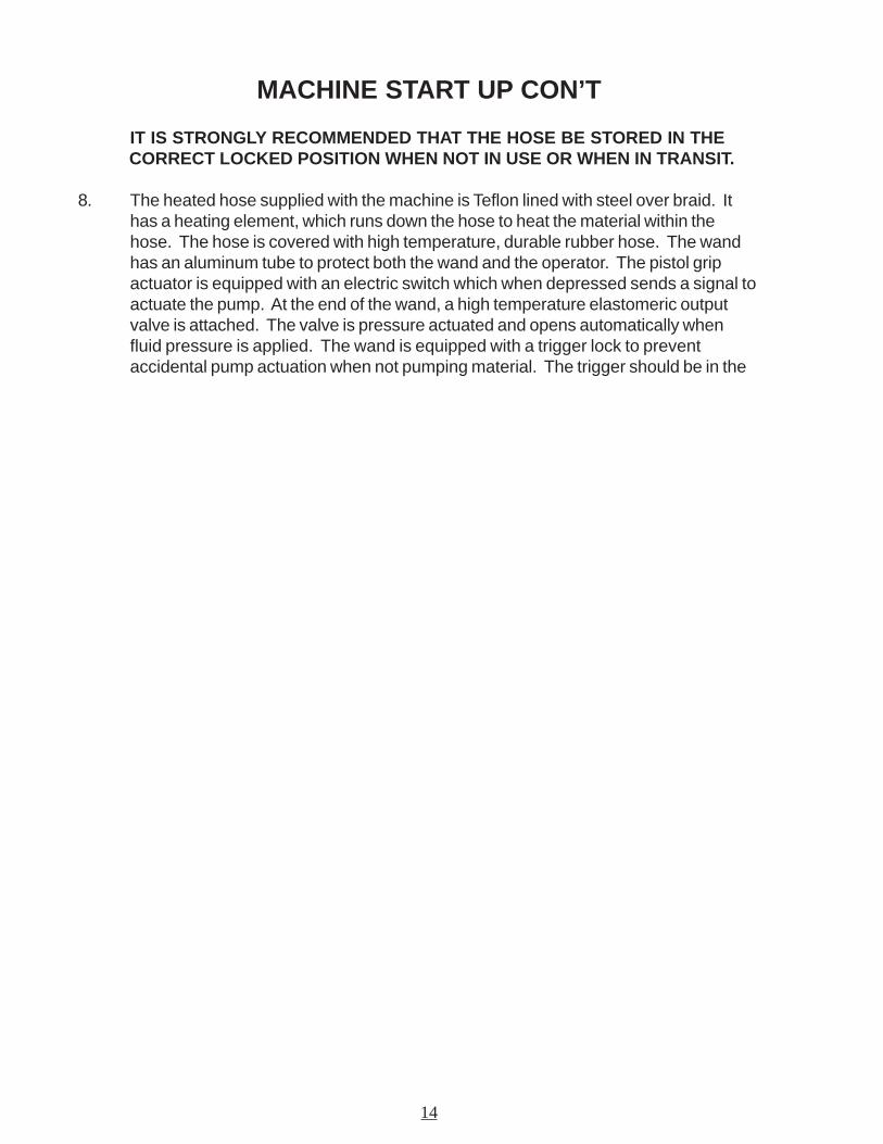
IT IS STRONGLY RECOMMENDED THAT THE HOSE BE STORED IN THE CORRECT LOCKED POSITION WHEN NOT IN USE OR WHEN IN TRANSIT.
8. The heated hose supplied with the machine is Teflon lined with steel over braid. Ithas a heating element, which runs down the hose to heat the material within thehose. The hose is covered with high temperature, durable rubber hose. The wandhas an aluminum tube to protect both the wand and the operator. The pistol gripactuator is equipped with an electric switch which when depressed sends a signal toactuate the pump. At the end of the wand, a high temperature elastomeric outputvalve is attached. The valve is pressure actuated and opens automatically whenfluid pressure is applied. The wand is equipped with a trigger lock to preventaccidental pump actuation when not pumping material. The trigger should be in the
15
DISPENSING THE MATERIAL
NOTE: PROTECTIVE CLOTHING, GLOVES, HARD SOLED SHOES,AND FACE SHIELD OR SAFETY GLASSES SHOULD BE WORNWHEN OPERATING OR FILLING THIS EQUIPMENT. READENTIRE MANUAL BEFORE OPERATING.
The wand is equipped with a disposable duckbill valve on the end which shuts off the flow ofmaterial when the pump is turned off and prevents excessive dripping of material. This valvealso directs the material into a stream for easy application into the crack. Other sealing tipsare available. See your local distributor for options.
Some difficulty may be encountered when starting up on cold days. Although the wand isdesigned to heat the material all the way down to the tip, on cold days it may be necessary toplace the tip of the wand under the lid to facilitate material melting in the valve. Insert the wandtip for only a short time before proceeding.
When the material and the hose have reached proper application temperature, you are readyto dispense material. Turn the pump speed control to the lowest setting by turning the controlknob to the minimum setting. With the wand tip inserted into the top of the melter, depresstrigger on the wand and slowly increase pump speed by turning the speed control knob to-wards the maximum setting until the pump motor starts to turn. Material should start to flowfrom the tip of the duckbill valve. Adjust the pump speed for the desired rate of flow for theapplication and dispense material as required. The rate of flow may be varied while the pumpis running by rotating the control knob.
If your machine has a shot timer option you will need to follow the following steps to dispensematerial. Locate the toggle switch in the main control box labeled “Pump”. this will allow you toswitch from Crack Sealing Mode to Marker Mode.
Crack Sealing ModeThis is the standard mode of crack sealing and you would follow the step above starting at thetop of this page to dispense material.
Marker ModeThis allows you to place a shot size between zero to 4 ounces each time you pull the trigger,there is a separate control box located near the main control box where the shot size can becontrolled. Inside this control box you will position the knob to the desired shot size.
NEVER POINT THE WAND AT ANY PART OF THE BODY ORAT ANY OTHER PERSON. HOT MATERIALS CAN CAUSESEVERE BURNS. WEAR PROTECTIVE EQUIPMENT WHENFILLING OR OPERATING THE EQUIPMENT. READ MANUALBEFORE OPERATING EQUIPMENT
16
ACTIVE PUMP PROTECTION
The pump is completely encircled by a protective screen. The screen shall not allow anythinglarger than 1/2” (1.27 cm) in size to pass from the sealant tank into the pump suction port. Thescreen shall continuously rotate 360 around the pump whenever the sealant agitator is en-gaged. The active screen will protect the pump from foreign object damage and will self cleanas it rotates around the sealant pump and suction port.
LOADING THE MACHINE
When loading solid material into the sealant tank, the mixer will stop when the lid is lifted.
To load, lift the lid, place the material on the lid and close lid. Following this procedure willprevent the hot material from splashing and causing serious burns to personnel.
The solid material must be added at intervals, which will allow the mixer to rotate withoutjamming. If blocks of material are fed in too quickly, jamming will result and slow down themelting process.
17
SHUTDOWN AND CLEAN-OUT PROCEDURE
When shutting down the machine for the day, there are several schools of thought about howmuch material to leave in the machine. Crafco recommends leaving the melter about half full.This will give a fairly rapid heat up rate in the morning, but will allow enoughmaterial to start dispensing right away when the material becomes molten.
1. Leaving the hose in the boom, swing the boom clockwise towards the front of themachine and lock the boom into position with the latch provided.
2. Place the wand in the wand holder and lock the wand into position with the latchprovided.
3. Reverse the pump for approximately 30 seconds.
4. Turn the “POWER” toggle switch “OFF”.
5. Turn the mixer toggle switch to “OFF”.
6. Shut the engine down by turning the key to the “OFF” position.
7. Turn LPG off at the line valve and the valve at LPG bottle.
STORING MACHINE
The melter should be stored in an area where moisture cannot enter machine heating system,such as hot oil, controls, etc. Extended down time can cause moisture build up in heating oiltank.
If there is any suspicion that moisture may have collected in heat transfer oil, warm heattransfer fluid to 300° F. for 2 to 3 hours to evaporate the moisture.

18
ELECTRIC HOSE CARE AND CAUTIONS
Twisting and kinking of the electric hose (used on LF, BAX, SS60, and SS125 Melter) is thenumber one cause of hose failure. When this happens, the electric heating wires are shortedout to the metal hose cover and the hose stops heating. This type of failure is not coveredunder the Crafco warranty.
To help prevent twisting and kinking and the resulting hose damage, the operator should:
a. Not move or use hose unless it has been turned on at least 35 minutes andset at a minimum temperature of 300° F.
b. Make sure hose swivel between hose and wand moves freely.
c. Limit the hose bending to a radius of 10 inches.
d. Avoid bending the hose over sharp edges such as the edge of the frame ortank.
e. Avoid twisting.
f. Do not exceed 400° F. on the hose controller or material temperature.
g. Follow all instructions of the melter as well as those in the instruction manual.
h. Avoid pulling hose beyond its limits.
19
HOSE TRANSPORT INSTRUCTIONS
1. Leaving the hose in the boom, swing the boom clockwise towards the front of themachine and lock the boom into position with the latch provided.
2. Place the wand in the wand holder and lock the wand into position with the latchprovided.
CAUTION:
Hose damage will occur if:
a. Hose is bent or moved when cold.
b. Hose is twisted or bent at less than a 10 inch radius.
c. Hose is moved prior to being turned on at least 35 minutes and set at380° F.
d. Operator crosses over or under hose causing hose to twist or wires betweenhose and wand connection to twist or wrap up.
e. Swivel is cold and not free to move allowing hose to twist.
f. Hose to wand wiring is pulled, stressed, or used to support the wand.
20
Fig. 1
MAINTENANCE INSTRUCTIONS
ENGINESee Engine Owner Manual for operating and maintenance instructions.
HYDRAULIC SYSTEMCheck hydraulic fluid daily. Change hydraulic filter every 250 hours of operation. Changehydraulic fluid every 500 hours of operation.
HEAT TRANSFER OILCheck oil level every 8 hours of operation. Change oil every 500 hours of operation.
WHEEL BEARINGSRe-pack wheel bearings every 24,000 miles or every two years, using a good grade of bear-ing grease.
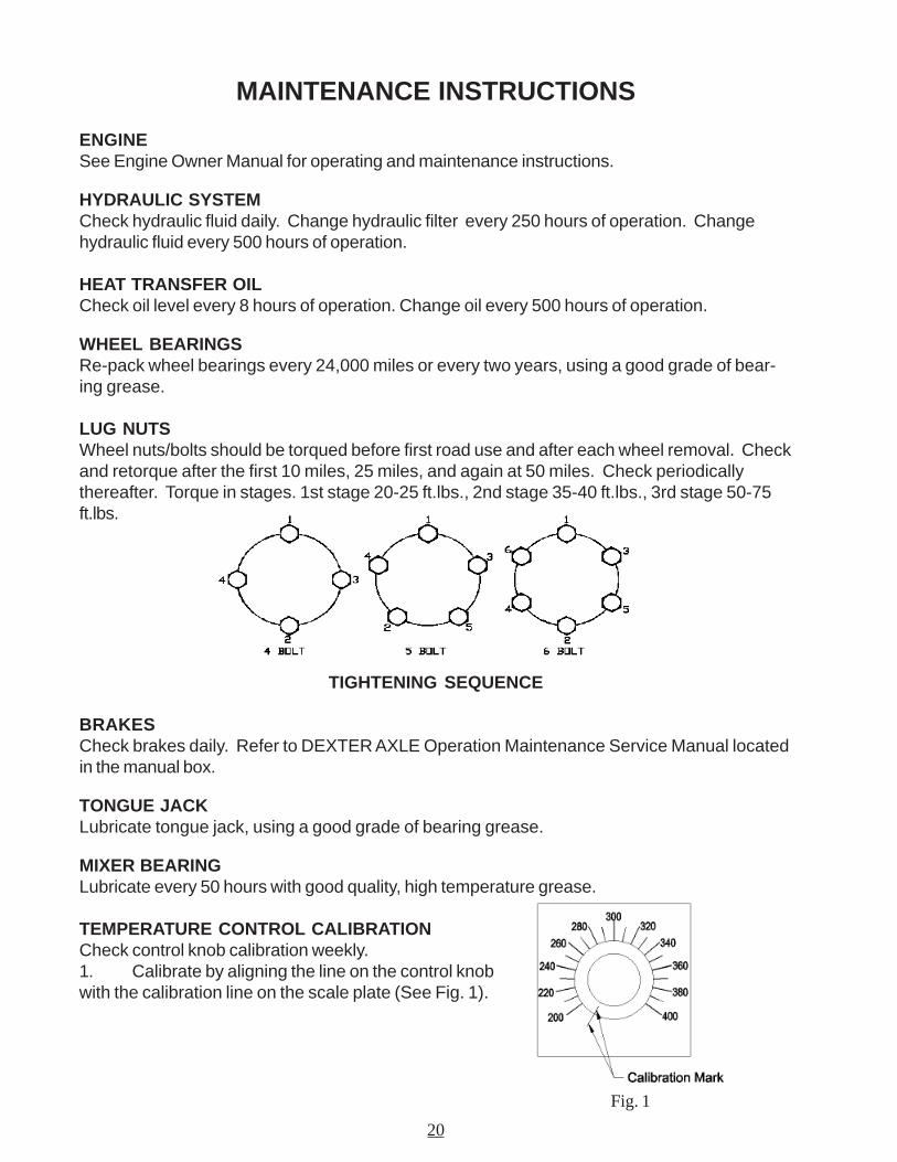
LUG NUTSWheel nuts/bolts should be torqued before first road use and after each wheel removal. Checkand retorque after the first 10 miles, 25 miles, and again at 50 miles. Check periodicallythereafter. Torque in stages. 1st stage 20-25 ft.lbs., 2nd stage 35-40 ft.lbs., 3rd stage 50-75ft.lbs.
TIGHTENING SEQUENCE
BRAKESCheck brakes daily. Refer to DEXTER AXLE Operation Maintenance Service Manual locatedin the manual box.
TONGUE JACKLubricate tongue jack, using a good grade of bearing grease.
MIXER BEARINGLubricate every 50 hours with good quality, high temperature grease.
TEMPERATURE CONTROL CALIBRATIONCheck control knob calibration weekly.1. Calibrate by aligning the line on the control knobwith the calibration line on the scale plate (See Fig. 1).
21
SERVICE INSTRUCTIONS
1. Conduct a general inspection of your machine at least once a week. Replace allworn or damaged parts, make any necessary adjustments, and tighten all loose nutsor screws.
2. Keep regular replacement items in stock for emergency repairs to avoid costly“down” time.
3. Watch for leaks. Tighten fitting or repair as necessary.
4. Clean machine externally periodically. Check with sealant manufacturer forrecommendation.
5. Follow recommended maintenance procedures on maintenance chart.
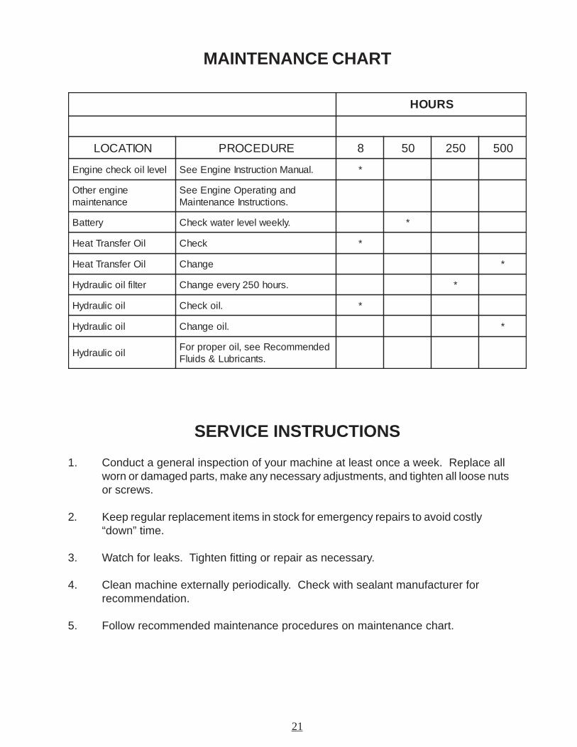
MAINTENANCE CHART
SRUOH
NOITACOL ERUDECORP 8 05 052 005
levelliokcehcenignE .launaMnoitcurtsnIenignEeeS *
enignerehtOecnanetniam
dnagnitarepOenignEeeS.snoitcurtsnIecnanetniaM
yrettaB .ylkeewlevelretawkcehC *
liOrefsnarTtaeH kcehC *
liOrefsnarTtaeH egnahC *
retlifliociluardyH .sruoh052yreveegnahC *
liociluardyH .liokcehC *
liociluardyH .lioegnahC *
liociluardyHdednemmoceRees,lioreporproF
.stnacirbuL&sdiulF
22
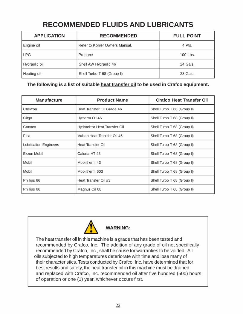
WARNING:
The heat transfer oil in this machine is a grade that has been tested andrecommended by Crafco, Inc. The addition of any grade of oil not specificallyrecommended by Crafco, Inc., shall be cause for warranties to be voided. All
oils subjected to high temperatures deteriorate with time and lose many oftheir characteristics. Tests conducted by Crafco, Inc. have determined that forbest results and safety, the heat transfer oil in this machine must be drainedand replaced with Crafco, Inc. recommended oil after five hundred (500) hoursof operation or one (1) year, whichever occurs first.
RECOMMENDED FLUIDS AND LUBRICANTS
The following is a list of suitable heat transfer oil to be used in Crafco equipment.
NOITACILPPA DEDNEMMOCER TNIOPLLUF
lioenignE .launaMsrenwOrelhoKotrefeR .stP4
GPL enaporP .sbL001
liociluardyH 64ciluardyHWAllehS .slaG42
liognitaeH )IIpuorG(86TobruTllehS .slaG32
erutcafunaM emaNtcudorP liOrefsnarTtaeHocfarC
norvehC 64edarGliOrefsnarTtaeH )IIpuorG(86TobruTllehS
ogtiC 64liOmrehtyH )IIpuorG(86TobruTllehS
oconoC liOrefsnarTtaeHraelcordyH )IIpuorG(86TobruTllehS
aniF 64liOrefsnarTtaeHnacluV )IIpuorG(86TobruTllehS
sreenignEnoitacirbuL liOrefsnarTtaeH )IIpuorG(86TobruTllehS
liboMnoxxE 34THairolaC )IIpuorG(86TobruTllehS
liboM 34mrehtliboM )IIpuorG(86TobruTllehS
liboM 306mrehtliboM )IIpuorG(86TobruTllehS
66spillihP 3#liOrefsnarTtaeH )IIpuorG(86TobruTllehS
66spillihP 86liOsungaM )IIpuorG(86TobruTllehS
23
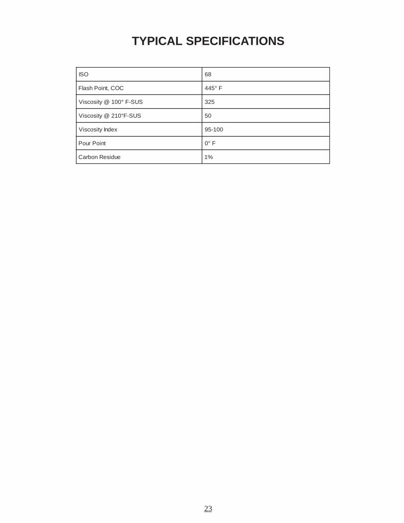
TYPICAL SPECIFICATIONS
OSI 86
COC,tnioPhsalF F°544
SUS-F°001@ytisocsiV 523
SUS-F°012@ytisocsiV 05
xednIytisocsiV 001-59
tnioPruoP F°0
eudiseRnobraC %1
24
SUPER SHOT PUMP REPLACEMENTStep 1Bring melter up to temperature as preparation for draining the material tank. Remove pipe cap located atrear of machine and drain tank (CAUTION!! EXTREMELY HOT MATERIAL).
Step 2Remove both guards from the motor mount to access the chain and sprockets.
Step 3Rotate agitator until connecting link is accessible. Disassemble the connecting link and remove the drivechain.
Step 4Loosen set screw in the lower coupling half between the hydraulic motor and the drive shaft.
Step 5Remove the (4) hydraulic hoses and cap off all ports. Note: Mark hoses for ease of replacement.
Step 6Remove the (4) bolts holding motor mount on top of melter. Lift off motor mounting and set aside.
Step 7Remove (2) bolts holding agitator shaft bearing. Note: Do not remove bearing from agitator shaft.
Step 8When unit has cooled sufficiently, remove (6) bolts holding paddles on top of screen. Remove paddles fromtank.
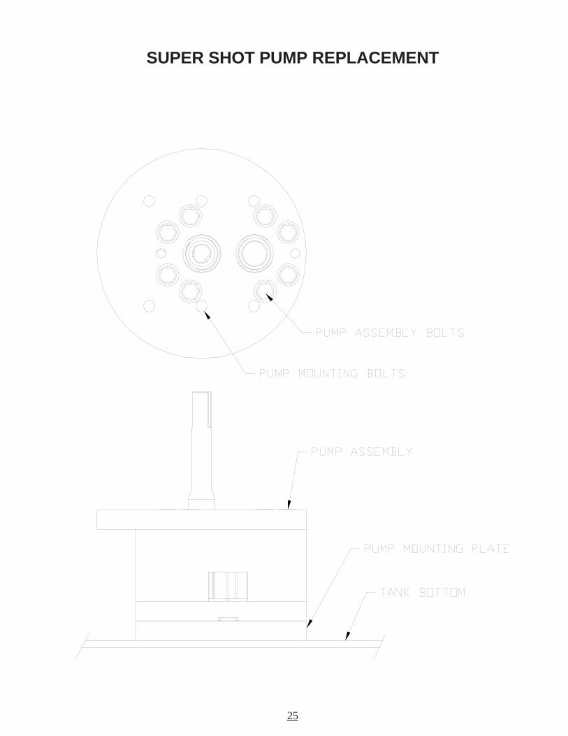
Step 9Remove pump drive shaft from center of agitator shaft then lift agitator shaft and screen assembly as high aspossible and insert screw driver into shaft hole. This will support the assembly while removing the pumpfrom the tank.
Step 10Remove the (6) bolts, which fasten the pump to the tank. Lift the pump from the material tank (CAUTION!!THE PUMP WEIGHS APPROXIMATELY 90LBS.)
Step 10IMPORTANT: Clean any sealant from top of pump mounting plate and clean-out shaft holes. (WARNING!!!PREMATURE PUMP WEAR WILL OCCUR IF THIS IS NOT DONE.)
25
SUPER SHOT PUMP REPLACEMENT
26
TROUBLE SHOOTING GUIDE
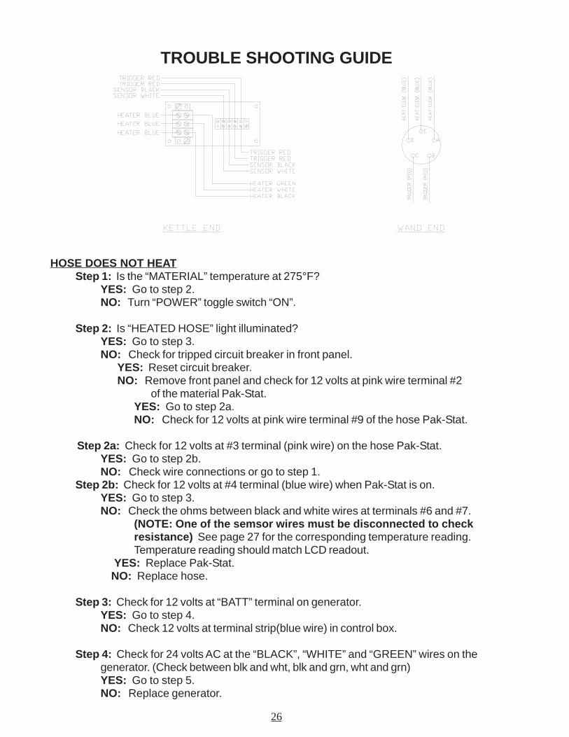
HOSE DOES NOT HEATStep 1: Is the “MATERIAL” temperature at 275°F?
YES: Go to step 2.NO: Turn “POWER” toggle switch “ON”.
Step 2: Is “HEATED HOSE” light illuminated?YES: Go to step 3.NO: Check for tripped circuit breaker in front panel.
YES: Reset circuit breaker.NO: Remove front panel and check for 12 volts at pink wire terminal #2
of the material Pak-Stat.YES: Go to step 2a.NO: Check for 12 volts at pink wire terminal #9 of the hose Pak-Stat.
Step 2a: Check for 12 volts at #3 terminal (pink wire) on the hose Pak-Stat.YES: Go to step 2b.NO: Check wire connections or go to step 1.
Step 2b: Check for 12 volts at #4 terminal (blue wire) when Pak-Stat is on.YES: Go to step 3.NO: Check the ohms between black and white wires at terminals #6 and #7.
(NOTE: One of the semsor wires must be disconnected to checkresistance) See page 27 for the corresponding temperature reading.Temperature reading should match LCD readout.
YES: Replace Pak-Stat. NO: Replace hose.
Step 3: Check for 12 volts at “BATT” terminal on generator.YES: Go to step 4.NO: Check 12 volts at terminal strip(blue wire) in control box.
Step 4: Check for 24 volts AC at the “BLACK”, “WHITE” and “GREEN” wires on thegenerator. (Check between blk and wht, blk and grn, wht and grn)YES: Go to step 5.NO: Replace generator.
27
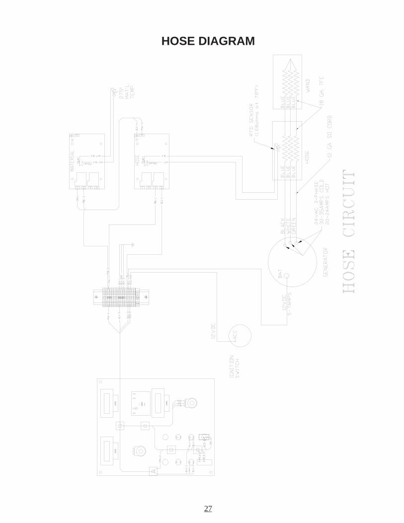
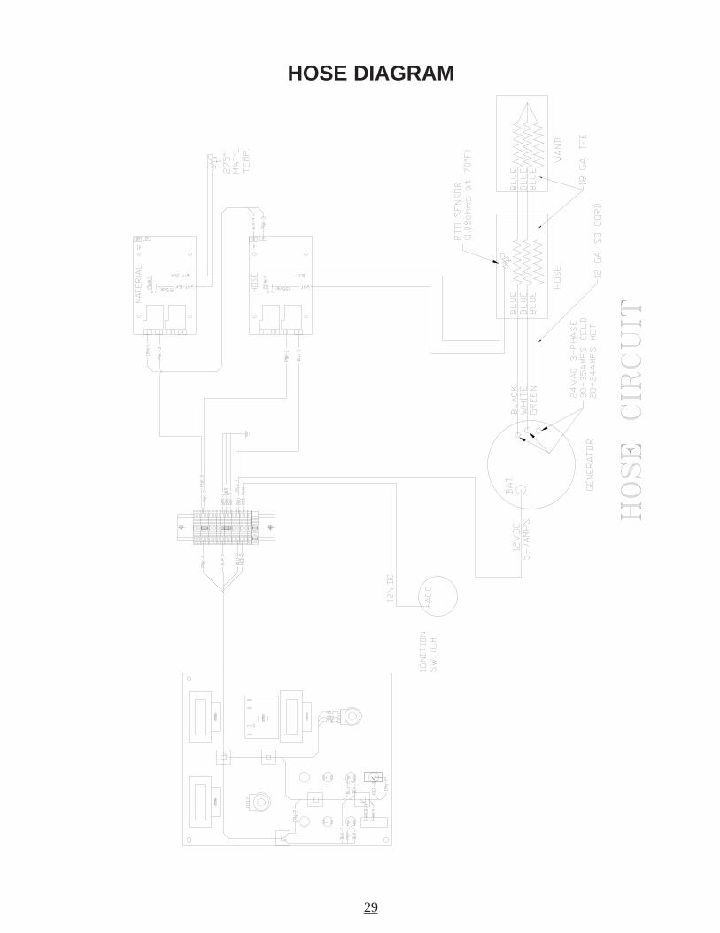
HOSE DIAGRAM
28
TROUBLE SHOOTING GUIDEStep 5: Check for 30 amps (cold) or 22-24 amps (hot) at the 3 blue wires in the
junction box. (Always use a clamp-on AMP meter to perform this test)YES: Hose should be operating properly.NO: Go to step 6.
Step 6: Check for continuity between three heating element wires (blue) in junction box. (NOTE: Wires must be disconnected from terminal block)YES: Go to step 7.NO: Check continuity between terminals “A”, “E”, and “D” at the wand.
YES: Wand is Ok. Go to step 7.NO: Replace wand.
Step 7: Check for continuity between element wires (blue) and the fitting of the hose.YES: Replace hose.NO: Hose is OK.
MATERIAL DOES NOT DISPENSE WHEN PUMP IS ACTIVATED
Step 1: Is the motor coupling turning?YES: Go to step 2.NO: Has the sealant had sufficient time to completely melt?
YES: Go to step 2.NO: Has the hose had sufficient time to reach operating temperature?
YES: Go to step 2.NO: Allow hose to heat up to operating temperature.
Step 2: Is the “MATERIAL” temperature at 275°F ?YES: Go to step 3.NO: Allow material to heat longer or turn “POWER” toggle switch “ON”.
Step 3: Is the “PUMP” light illuminated?YES: Go to step 4.NO: Hose temperature must be at 325°F before the pump will activate.
Step 4: Check for 12 volts at terminals #12 (red-blk wire) and terminal #14 (greenwire) of the relay. (NOTE: Terminal #12 will have 12 volts when the keyis “ON”. Terminal #14 will have 12 volts when trigger is activated.)
YES: Go to step 4a.NO: Check continuity of red trigger wires in junction box.
Yes: Go to step 5.No: Check for continuity between terminals “C” and “B” on wand when the trigger is activated.
YES: Go to step 5.NO: Replace trigger or check for poor connections.
Step 4a: Check relay by pressing the white test button on top of relay. (CAUTION: Pump will dispense material).
YES: Go to step 5.NO: Replace relay.
29
HOSE DIAGRAM
30
Step 5: Is the top right light on hydraulic valve illuminated (looking at the rear of thehydraulic valve) when trigger is activated?
YES: Replace hydraulic cartridge.NO: Go to step 4.
PUMP ROTATES BUT NO MATERIAL IS DISCHARGED
Step 1: Has the sealant and heated hose had sufficient time to reach temperature?YES: Go to step 2.NO: Allow the sealant and hose to heat longer.
Step 2: Check material outlet pipe and connection between hose and wand forobstruction.
YES: Remove obstruction and reassemble hose connection.NO: Go to step 3.
Step 3: Is there an obstruction at the pump suction?YES: Reverse material pump for 30 seconds.NO: Refer to page 20 for pump removal if required.
TROUBLE SHOOTING GUIDE
MATERIAL DISPENSING RATE IS TOO SLOW
Step 1: Check speed control knob for desired flow adjustment.YES: Go to step 2.NO: Adjust to desired flow.
Step 2: Is there enough material in the tank?YES: Go to step 3.NO: Add enough material to bring tank level above the screen.
Step 3: Check material outlet pipe and connection between hose and wand forobstruction.
YES: Remove obstruction and reassemble hose connection.NO: Pump is worn out (See page 20 for pump removal and installation).

31
RTD SENSOR - OHMS vs. TEMPERATURE
The following chart shows what the ohm reading would be for a given temperature. This is tobe used when trouble shooting the burner and the hose. The following are the instructions foruse.
1. Measure the resistance(Ohms) of the sensor in question with an Ohm meter.2. Find the reading in the chart.3. Follow the row to the left and get the temperature in 10° increment, then follow the
column up to get the 1° increment. Example: 1573 Ohms =302°
F° 0 1 2 3 4 5 6 7 8 9
0 3.039 5.239 7.439 9.639 1.939 3.149 4.349 6.549 8.749 0.059
01 2.259 3.459 5.659 7.859 9.069 0.369 2.569 4.769 6.969 8.179
02 9.379 1.679 3.879 5.089 6.289 8.489 0.789 1.989 3.199 5.399
03 7.599 8.799 0.0001 2.2001 3.4001 5.6001 7.8001 9.0101 0.3101 2.5101
04 4.7101 5.9101 7.1201 9.3201 0.6201 2.8201 4.0301 5.2301 7.4301 9.6301
05 0.9301 2.1401 4.3401 5.5401 7.7401 8.9401 0.2501 2.4501 3.6501 5.8501
06 7.0601 8.2601 0.5601 1.7601 3.9601 5.1701 6.3701 8.5701 9.7701 1.0801
07 2.2801 4.4801 6.6801 7.8801 9.0901 0.3901 2.5901 3.7901 5.9901 6.1011
08 8.3011 0.6011 1.8011 3.0111 4.2111 6.4111 7.6111 9.8111 0.1211 2.3211
09 3.5211 5.7211 6.9211 8.1311 9.3311 1.6311 2.8311 4.0411 5.2411 7.4411
001 8.6411 0.9411 1.1511 2.3511 4.5511 5.7511 7.9511 8.1611 0.4611 1.6611
011 3.8611 4.0711 5.2711 7.4711 9.6711 0.9711 1.1811 3.3811 4.5811 5.7811
021 7.9811 8.1911 0.4911 1.6911 2.8911 4.0021 5.2021 6.4021 8.6021 9.8021
031 0.1121 2.3121 3.5121 5.7121 6.9121 7.1221 9.3221 0.6221 1.8221 3.0321
041 4.2321 5.4321 7.6321 9.8321 9.0421 0.3421 2.5421 3.7421 4.9421 6.1521
051 7.3521 8.5521 0.8521 1.0621 2.2621 3.4621 5.6621 6.8621 7.0721 8.2721
061 0.5721 1.7721 2.9721 3.1821 5.3821 6.5821 7.7821 8.9821 0.2921 1.4921
071 2.6921 3.8921 4.0031 6.2031 7.4031 8.6031 9.8031 0.1131 2.3131 3.5131
081 4.7131 5.9131 6.1231 8.3231 9.5231 0.8231 1.0331 2.2331 3.4331 5.6331
091 6.8331 7.0431 8.2431 9.4431 0.7431 1.9431 2.1531 4.3531 5.5531 6.7531
002 7.9531 8.1631 9.3631 0.6631 1.8631 2.0731 4.2731 5.4731 6.6731 7.8731
012 8.0831 9.2831 0.5831 1.7831 2.9831 3.1931 4.3931 5.5931 6.7931 7.9931
022 8.1041 9.3041 0.6041 1.8041 3.0141 4.2141 5.4141 6.6141 7.8141 8.0241
032 9.2241 0.5241 1.7241 2.9241 3.1341 4.3341 5.5341 6.7341 6.9341 7.1441
042 8.3441 9.5441 0.8441 1.0541 2.2541 3.4541 4.6541 5.8541 6.0641 7.2641
052 8.4641 9.6641 0.9641 1.1741 2.3741 3.5741 3.7741 4.9741 5.1841 6.3841
062 7.5841 8.7841 9.9841 0.2941 1.4941 1.6941 2.8941 3.0051 4.2051 5.4051
072 6.6051 7.8051 8.0151 8.2151 9.4151 0.7151 1.9151 2.1251 3.3251 3.5251
082 4.7251 5.9251 6.1351 7.3351 7.5351 8.7351 9.9351 0.2451 1.4451 1.6451
092 2.8451 3.0551 4.2551 5.4551 5.6551 6.8551 7.0651 8.2651 8.4651 9.6651
003 0.9651 1.1751 1.3751 2.5751 3.7751 4.9751 4.1851 5.3851 6.5851 7.7851
013 7.9851 8.1951 9.3951 9.5951 0.8951 1.0061 2.2061 2.4061 3.6061 4.8061
023 4.0161 5.2161 6.4161 6.6161 7.8161 8.0261 8.2261 9.4261 0.7261 0.9261
033 1.1361 2.3361 2.5361 3.7361 3.9361 4.1461 5.3461 5.5461 6.7461 7.9461
043 7.1561 8.3561 8.5561 9.7561 0.0661 0.2661 1.4661 1.6661 2.8661 2.0761
053 3.2761 4.4761 4.6761 5.8761 5.0861 6.2861 6.4861 7.6861 7.8861 8.0961
063 9.2961 9.4961 0.7961 0.9961 1.1071 1.3071 2.5071 2.7071 3.9071 3.1171
073 4.3171 4.5171 5.7171 5.9171 6.1271 6.3271 7.5271 7.7271 8.9271 8.1371
083 9.3371 9.5371 9.7371 0.0471 0.2471 1.4471 1.6471 2.8471 2.0571 3.2571
093 3.4571 3.6571 4.8571 4.0671 5.2671 5.4671 6.6671 6.8671 6.0771 7.2771
004 7.4771 8.6771 8.8771 8.0871 9.2871 9.4871 9.6871 0.9871 0.1971 1.3971
014 1.5971 1.7971 2.9971 2.1081 2.3081 3.5081 3.7081 3.9081 4.1181 4.3181
024 4.5181 5.7181 5.9181 5.1281 6.3281 6.5281 6.7281 6.9281 7.1381 7.3381
034 7.5381 8.7381 8.9381 8.1481 8.3481 9.5481 9.7481 9.9481 9.1581 0.4581
044 0.6581 0.8581 0.0681 1.2681 1.4681 1.6681 1.8681 2.0781 2.2781 2.4781
054 2.6781 2.8781 3.0881 3.2881 3.4881 3.6881 3.8881 4.0981 4.2981 4.4981
064 4.6981 4.8981 5.0091 5.2091 5.4091 5.6091 5.8091 5.0191 6.2191 6.4191
074 6.6191 6.8191 6.0291 6.2291 6.4291 6.6291 7.8291 7.0391 7.2391 7.4391
084 7.6391 7.8391 7.0491 7.2491 7.4491 8.6491 8.8491 8.0591 8.2591 8.4591
094 8.6591 8.8591 8.0691 8.2691 8.4691 8.6691 8.8691 8.0791 8.2791 8.4791
005 8.6791 8.8791 8.0891 9.2891 9.4891 9.6891 9.8891 9.0991 9.2991 9.4991
015 9.6991 9.8991 9.0002 9.2002 9.4002 9.6002 8.8002 8.0102 8.2102 8.4102
025 8.6102 8.8102 8.0202 8.2202 8.4202 8.6202 8.8202 8.0302 8.2302 8.4302
035 8.6302 8.8302 8.0402 8.2402 7.4402 7.6402 7.8402 7.0502 7.2502 7.4502
045 7.6502 7.8502 7.0602 7.2602 6.4602 6.6602 6.8602 6.0702 6.2702 6.4702
055 6.6702 5.8702 5.0802 5.2802 5.4802 5.6802 5.8802 4.0902 4.2902 4.4902
32
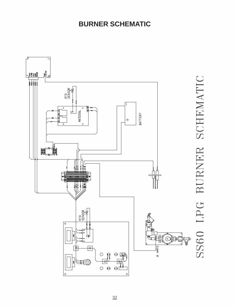
BURNER SCHEMATIC
33
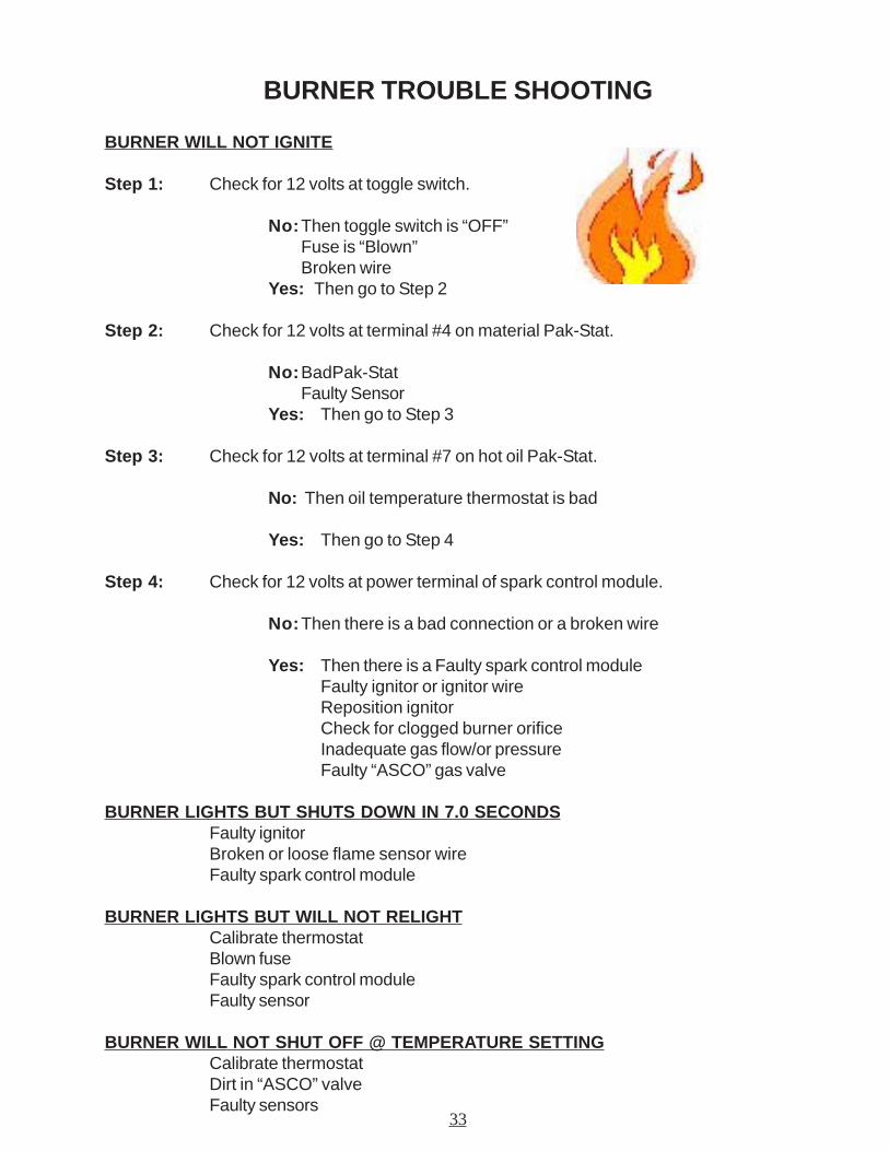
BURNER TROUBLE SHOOTING
BURNER WILL NOT IGNITE
Step 1: Check for 12 volts at toggle switch.
No:Then toggle switch is “OFF”Fuse is “Blown”Broken wire
Yes: Then go to Step 2
Step 2: Check for 12 volts at terminal #4 on material Pak-Stat.
No:BadPak-StatFaulty Sensor
Yes: Then go to Step 3
Step 3: Check for 12 volts at terminal #7 on hot oil Pak-Stat.
No: Then oil temperature thermostat is bad
Yes: Then go to Step 4
Step 4: Check for 12 volts at power terminal of spark control module.
No:Then there is a bad connection or a broken wire
Yes: Then there is a Faulty spark control moduleFaulty ignitor or ignitor wireReposition ignitorCheck for clogged burner orificeInadequate gas flow/or pressureFaulty “ASCO” gas valve
BURNER LIGHTS BUT SHUTS DOWN IN 7.0 SECONDSFaulty ignitorBroken or loose flame sensor wireFaulty spark control module
BURNER LIGHTS BUT WILL NOT RELIGHTCalibrate thermostatBlown fuseFaulty spark control moduleFaulty sensor
BURNER WILL NOT SHUT OFF @ TEMPERATURE SETTINGCalibrate thermostatDirt in “ASCO” valveFaulty sensors
34
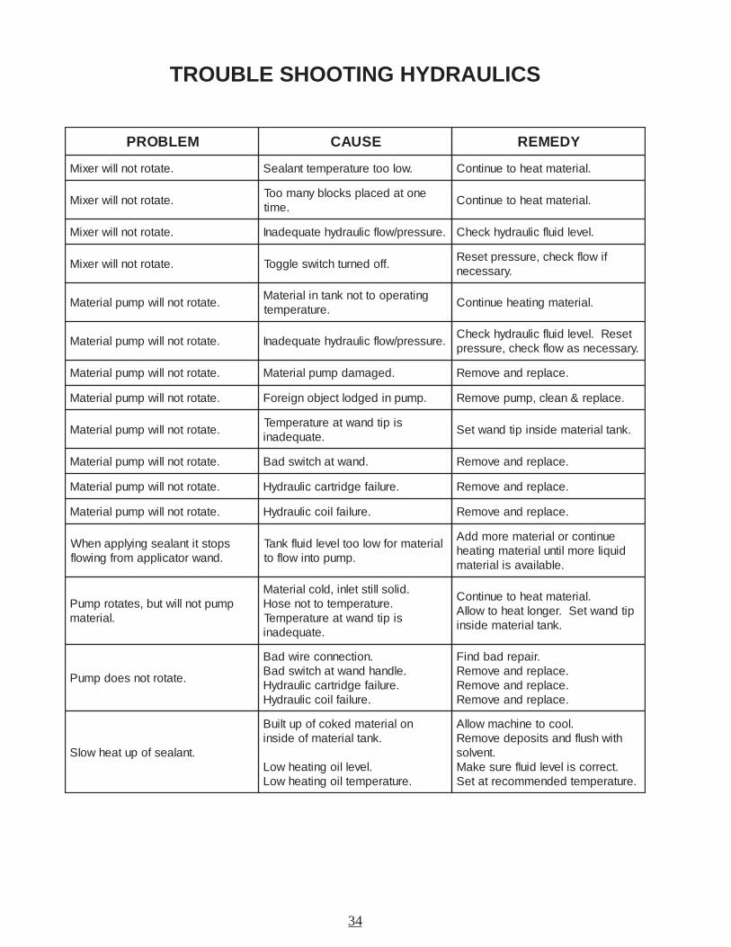
TROUBLE SHOOTING HYDRAULICS
MELBORP ESUAC YDEMER
.etatortonlliwrexiM .wolooterutarepmettnalaeS .lairetamtaehoteunitnoC
.etatortonlliwrexiMenotadecalpskcolbynamooT
.emit.lairetamtaehoteunitnoC
.etatortonlliwrexiM .erusserp/wolfciluardyhetauqedanI .leveldiulfciluardyhkcehC
.etatortonlliwrexiM .ffodenruthctiwselggoTfiwolfkcehc,erusserpteseR
.yrassecen
.etatortonlliwpmuplairetaMgnitarepoottonknatnilairetaM
.erutarepmet.lairetamgnitaeheunitnoC
.etatortonlliwpmuplairetaM .erusserp/wolfciluardyhetauqedanIteseR.leveldiulfciluardyhkcehC
.yrassecensawolfkcehc,erusserp
.etatortonlliwpmuplairetaM .degamadpmuplairetaM .ecalperdnaevomeR
.etatortonlliwpmuplairetaM .pmupnidegdoltcejbongieroF .ecalper&naelc,pmupevomeR
.etatortonlliwpmuplairetaMsipitdnawtaerutarepmeT
.etauqedani.knatlairetamedisnipitdnawteS
.etatortonlliwpmuplairetaM .dnawtahctiwsdaB .ecalperdnaevomeR
.etatortonlliwpmuplairetaM .eruliafegdirtracciluardyH .ecalperdnaevomeR
.etatortonlliwpmuplairetaM .eruliafliocciluardyH .ecalperdnaevomeR
spotstitnalaesgniylppanehW.dnawrotacilppamorfgniwolf
lairetamrofwolootleveldiulfknaT.pmupotniwolfot
eunitnocrolairetameromddAdiuqileromlitnulairetamgnitaeh
.elbaliavasilairetam
pmuptonlliwtub,setatorpmuP.lairetam
.dilosllitstelni,dloclairetaM.erutarepmetottonesoHsipitdnawtaerutarepmeT
.etauqedani
.lairetamtaehoteunitnoCpitdnawteS.regnoltaehotwollA
.knatlairetamedisni
.etatortonseodpmuP
.noitcennoceriwdaB.eldnahdnawtahctiwsdaB
.eruliafegdirtracciluardyH.eruliafliocciluardyH
.riaperdabdniF.ecalperdnaevomeR.ecalperdnaevomeR.ecalperdnaevomeR
.tnalaesfoputaehwolS
nolairetamdekocfoputliuB.knatlairetamfoedisni
.levelliognitaehwoL.erutarepmetliognitaehwoL
.loocotenihcamwollAhtiwhsulfdnastisopedevomeR
.tnevlos.tcerrocsileveldiulferusekaM
.erutarepmetdednemmocertateS
35
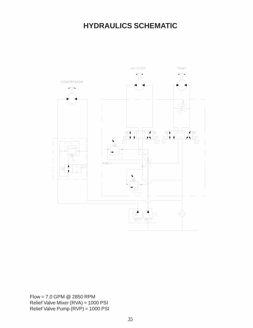
HYDRAULICS SCHEMATIC
Flow = 7.0 GPM @ 2850 RPMRelief Valve Mixer (RVA) = 1000 PSIRelief Valve Pump (RVP) = 1000 PSI
36
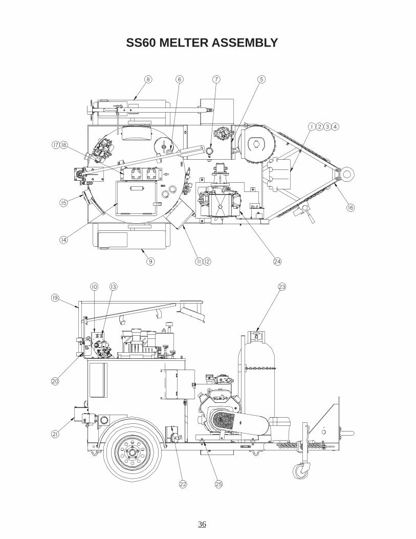
SS60 MELTER ASSEMBLY
8 6 7 5
1 2 3 4
16
2411 129
14
15
17 18
23
22 25
21
20
13
19
10
37
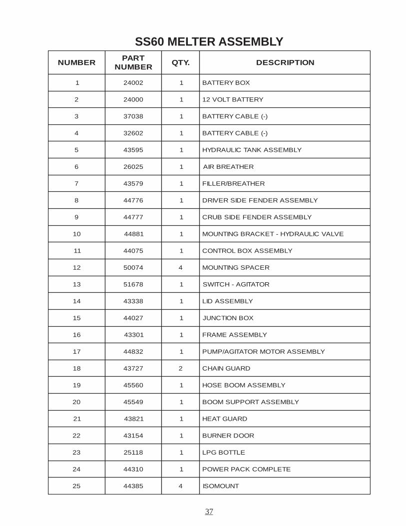
SS60 MELTER ASSEMBLY
REBMUNTRAP
REBMUN.YTQ NOITPIRCSED
1 20042 1 XOBYRETTAB
2 00042 1 YRETTABTLOV21
3 83073 1 )-(ELBACYRETTAB
4 20623 1 )-(ELBACYRETTAB
5 59534 1 YLBMESSAKNATCILUARDYH
6 52062 1 REHTAERBRIA
7 97534 1 REHTAERB/RELLIF
8 67744 1 YLBMESSAREDNEFEDISREVIRD
9 77744 1 YLBMESSAREDNEFEDISBURC
01 18844 1 EVLAVCILUARDYH-TEKCARBGNITNUOM
11 57044 1 YLBMESSAXOBLORTNOC
21 47005 4 RECAPSGNITNUOM
31 87615 1 ROTATIGA-HCTIWS
41 83334 1 YLBMESSADIL
51 72044 1 XOBNOITCNUJ
61 10334 1 YLBMESSAEMARF
71 23844 1 YLBMESSAROTOMROTATIGA/PMUP
81 72734 2 DRAUGNIAHC
91 06554 1 YLBMESSAMOOBESOH
02 94554 1 YLBMESSATROPPUSMOOB
12 12834 1 DRAUGTAEH
22 45134 1 ROODRENRUB
32 81152 1 ELTTOBGPL
42 01344 1 ETELPMOCKCAPREWOP
52 58344 4 TNUOMOSI
38
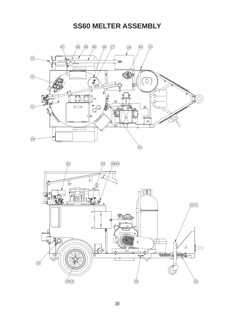
SS60 MELTER ASSEMBLY
37
4647 48 49 2726 39 45 33
43
34
51
41
42 40 38 44
30 31
323628 29
35
39
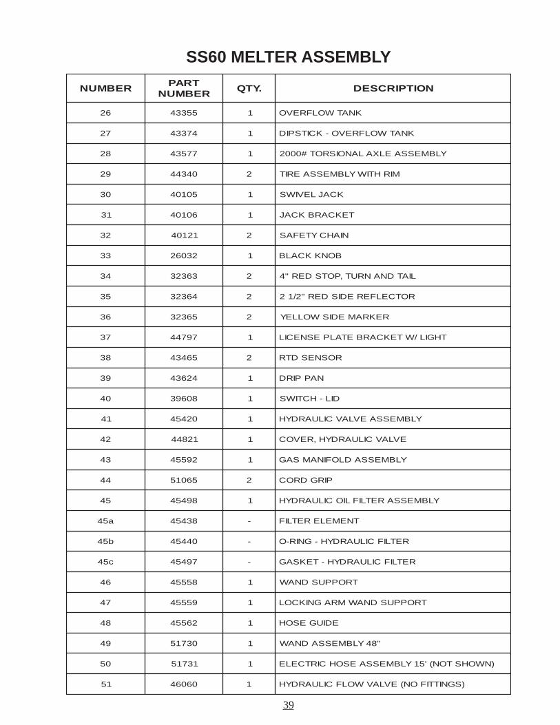
SS60 MELTER ASSEMBLY
REBMUNTRAP
REBMUN.YTQ NOITPIRCSED
62 55334 1 KNATWOLFREVO
72 47334 1 KNATWOLFREVO-KCITSPID
82 77534 1 YLBMESSAELXALANOISROT#0002
92 04344 2 MIRHTIWYLBMESSAERIT
03 50104 1 KCAJLEVIWS
13 60104 1 TEKCARBKCAJ
23 12104 2 NIAHCYTEFAS
33 23062 1 BONKKCALB
43 36323 2 LIATDNANRUT,POTSDER"4
53 46323 2 ROTCELFEREDISDER"2/12
63 56323 2 REKRAMEDISWOLLEY
73 79744 1 THGIL/WTEKCARBETALPESNECIL
83 56434 2 ROSNESDTR
93 42634 1 NAPPIRD
04 80693 1 DIL-HCTIWS
14 02454 1 YLBMESSAEVLAVCILUARDYH
24 12844 1 EVLAVCILUARDYH,REVOC
34 29554 1 YLBMESSADLOFINAMSAG
44 56015 2 PIRGDROC
54 89454 1 YLBMESSARETLIFLIOCILUARDYH
a54 83454 - TNEMELERETLIF
b54 04454 - RETLIFCILUARDYH-GNIR-O
c54 79454 - RETLIFCILUARDYH-TEKSAG
64 85554 1 TROPPUSDNAW
74 95554 1 TROPPUSDNAWMRAGNIKCOL
84 26554 1 EDIUGESOH
94 03715 1 "84YLBMESSADNAW
05 13715 1 )NWOHSTON('51YLBMESSAESOHCIRTCELE
15 06064 1 )SGNITTIFON(EVLAVWOLFCILUARDYH
40
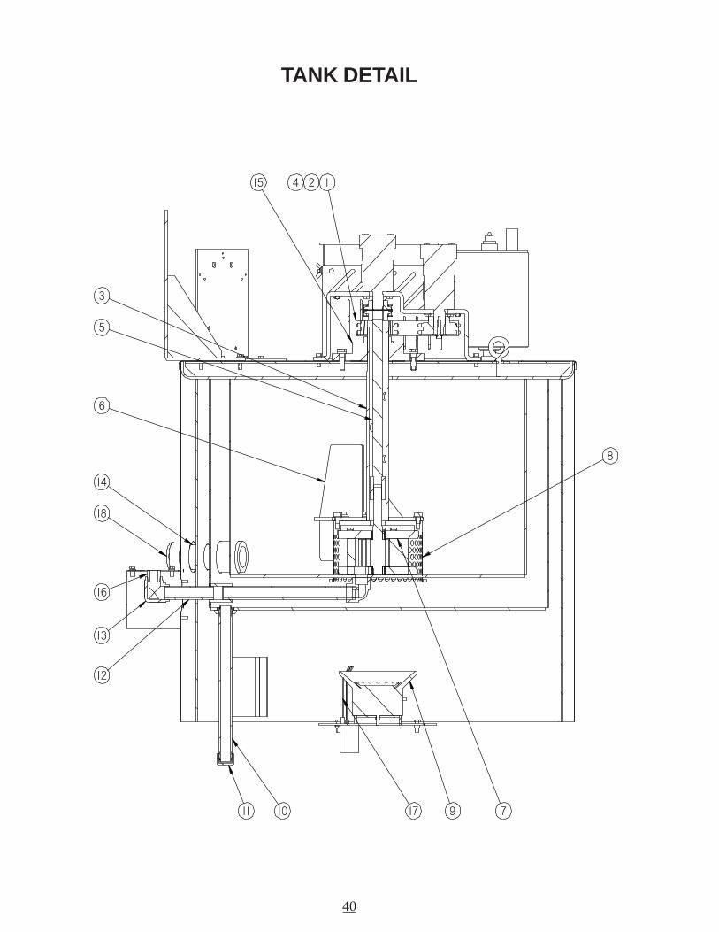
TANK DETAIL
12415
3
5
6
8
17 711 10
12
13
16
14
18
9
41
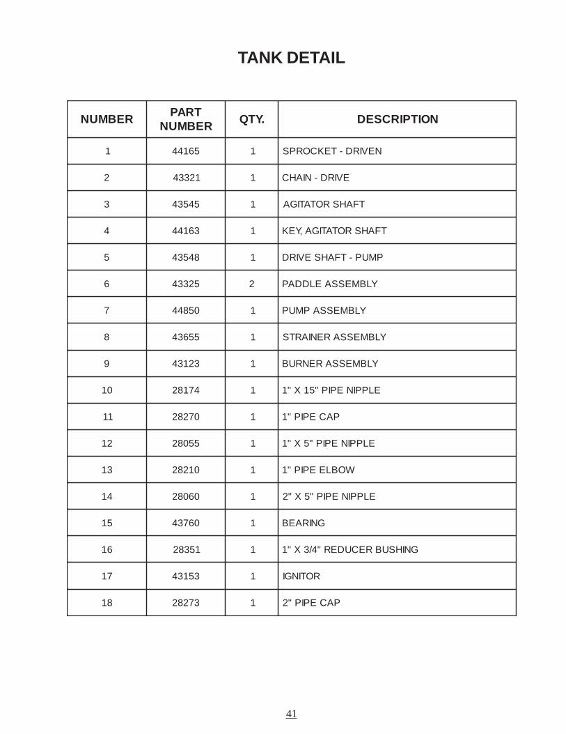
TANK DETAIL
REBMUNTRAP
REBMUN.YTQ NOITPIRCSED
1 56144 1 NEVIRD-TEKCORPS
2 12334 1 EVIRD-NIAHC
3 54534 1 TFAHSROTATIGA
4 36144 1 TFAHSROTATIGA,YEK
5 84534 1 PMUP-TFAHSEVIRD
6 52334 2 YLBMESSAELDDAP
7 05844 1 YLBMESSAPMUP
8 55634 1 YLBMESSARENIARTS
9 32134 1 YLBMESSARENRUB
01 47182 1 ELPPINEPIP"51X"1
11 07282 1 PACEPIP"1
21 55082 1 ELPPINEPIP"5X"1
31 01282 1 WOBLEEPIP"1
41 06082 1 ELPPINEPIP"5X"2
51 06734 1 GNIRAEB
61 15382 1 GNIHSUBRECUDER"4/3X"1
71 35134 1 ROTINGI
81 37282 1 PACEPIP"2
42
CONTROL BOX ASSEMBLY
43
CONTROL BOX ASSEMBLY
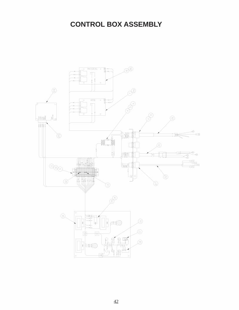
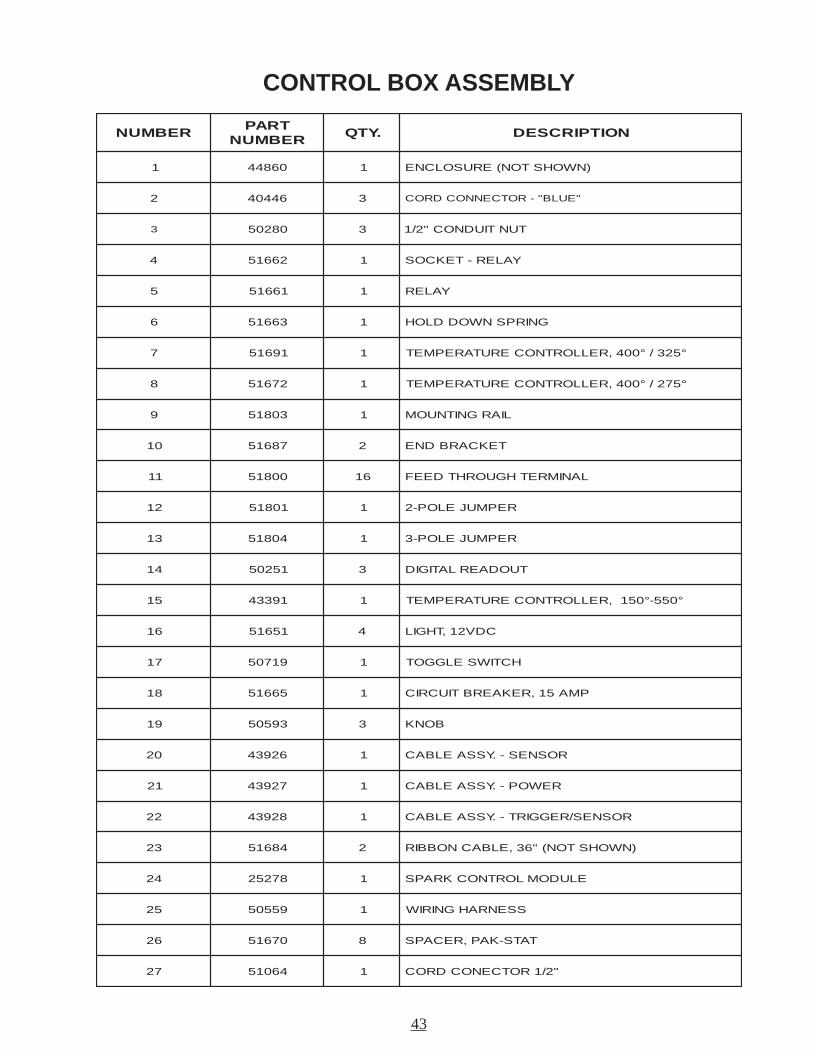
REBMUNTRAP
REBMUN.YTQ NOITPIRCSED
1 06844 1 )NWOHSTON(ERUSOLCNE
2 64404 3 "EULB"-ROTCENNOCDROC
3 08205 3 TUNTIUDNOC"2/1
4 26615 1 YALER-TEKCOS
5 16615 1 YALER
6 36615 1 GNIRPSNWODDLOH
7 19615 1 °523/°004,RELLORTNOCERUTAREPMET
8 27615 1 °572/°004,RELLORTNOCERUTAREPMET
9 30815 1 LIARGNITNUOM
01 78615 2 TEKCARBDNE
11 00815 61 LANIMRETHGUORHTDEEF
21 10815 1 REPMUJELOP-2
31 40815 1 REPMUJELOP-3
41 15205 3 TUODAERLATIGID
51 19334 1 °055-°051,RELLORTNOCERUTAREPMET
61 15615 4 CDV21,THGIL
71 91705 1 HCTIWSELGGOT
81 56615 1 PMA51,REKAERBTIUCRIC
91 39505 3 BONK
02 62934 1 ROSNES-.YSSAELBAC
12 72934 1 REWOP-.YSSAELBAC
22 82934 1 ROSNES/REGGIRT-.YSSAELBAC
32 48615 2 )NWOHSTON("63,ELBACNOBBIR
42 87252 1 ELUDOMLORTNOCKRAPS
52 95505 1 SSENRAHGNIRIW
62 07615 8 TATS-KAP,RECAPS
72 46015 1 "2/1ROTCENOCDROC
44
GAS MANIFOLD ASSEMBLY
1 2 3 4 5 6 7 8
9
10
11
12
13
14
15
16
17
18
19
45
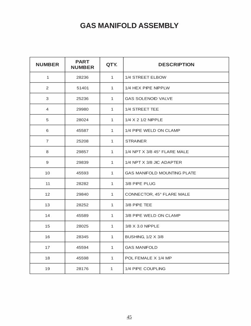
GAS MANIFOLD ASSEMBLY
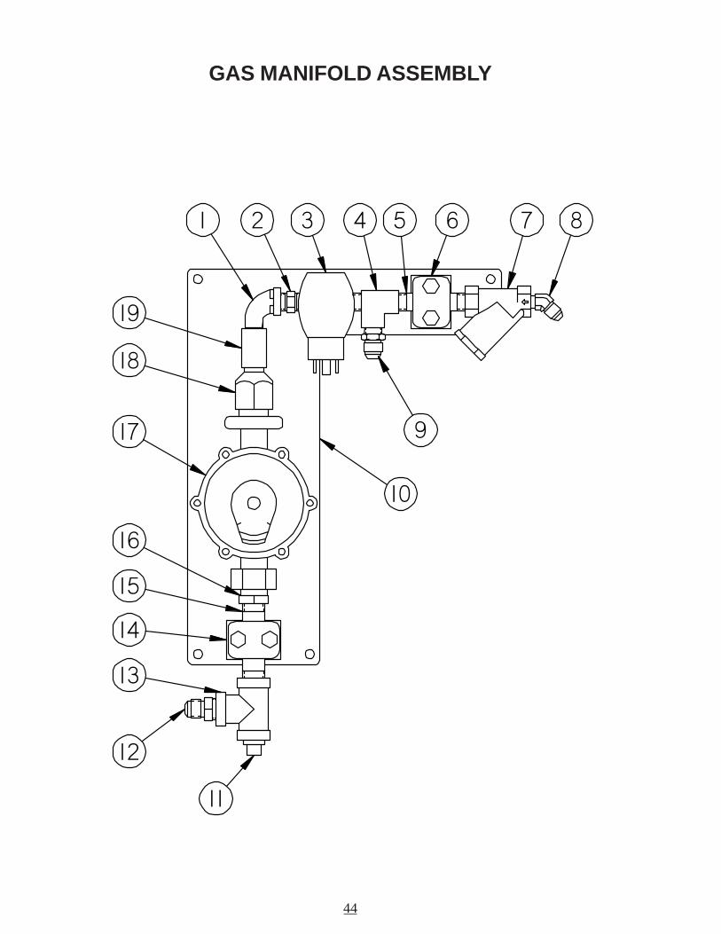
REBMUNTRAP
REBMUN.YTQ NOITPIRCSED
1 63282 1 WOBLETEERTS4/1
2 10415 1 WLPPINEPIPXEH4/1
3 63252 1 EVLAVDIONELOSSAG
4 08992 1 EETTEERTS4/1
5 42082 1 ELPPIN2/12X4/1
6 78554 1 PMALCNODLEWEPIP4/1
7 80252 1 RENIARTS
8 75892 1 ELAMERALF°548/3XTPN4/1
9 93892 1 RETPADACIJ8/3XTPN4/1
01 39554 1 ETALPGNITNUOMDLOFINAMSAG
11 28282 1 GULPEPIP8/3
21 04892 1 ELAMERALF°54,ROTCENNOC
31 25282 1 EETEPIP8/3
41 98554 1 PMALCNODLEWEPIP8/3
51 52082 1 ELPPIN0.3X8/3
61 54382 1 8/3X2/1,GNIHSUB
71 49554 1 DLOFINAMSAG
81 89554 1 PM4/1XELAMEFLOP
91 67182 1 GNILPUOCEPIP4/1
46
POWER - PACK ASSEMBLY
1
2
3
4
5
6
7
89
11 1213
14
15
16
47
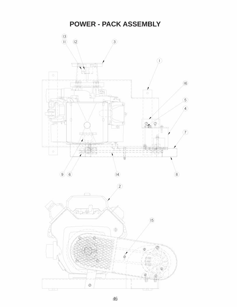
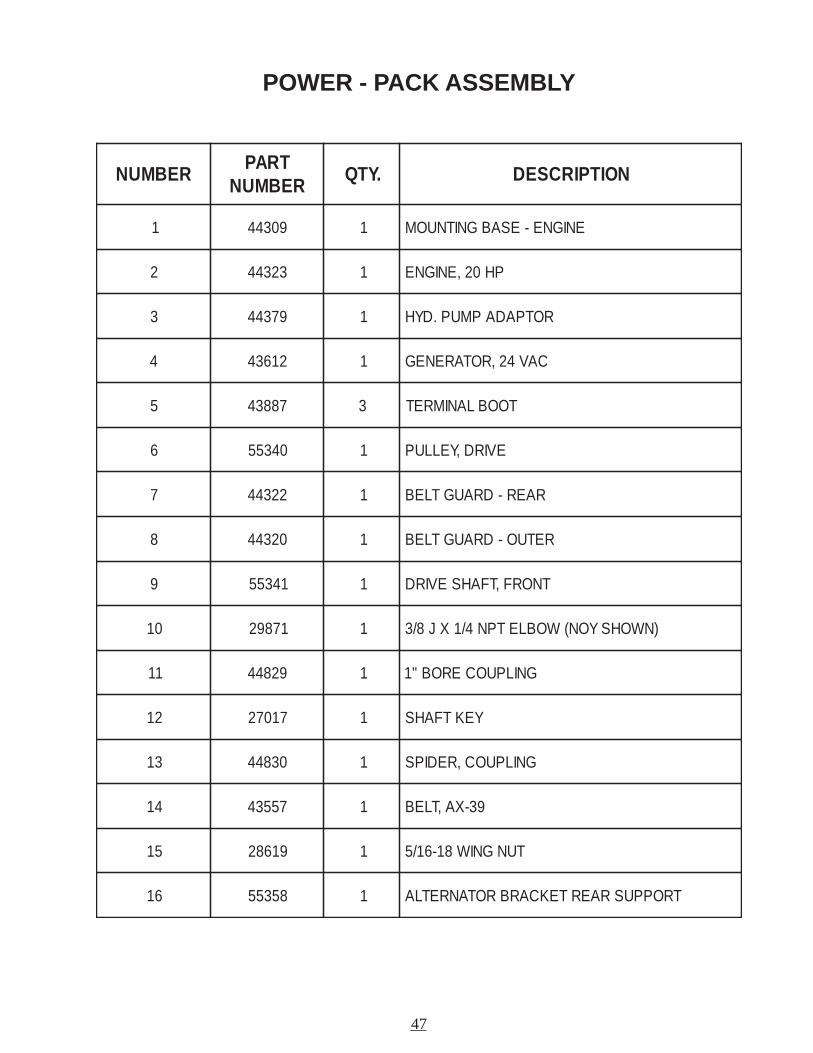
POWER - PACK ASSEMBLY
REBMUNTRAP
REBMUN.YTQ NOITPIRCSED
1 90344 1 ENIGNE-ESABGNITNUOM
2 32344 1 PH02,ENIGNE
3 97344 1 ROTPADAPMUP.DYH
4 21634 1 CAV42,ROTARENEG
5 78834 3 TOOBLANIMRET
6 04355 1 EVIRD,YELLUP
7 22344 1 RAER-DRAUGTLEB
8 02344 1 RETUO-DRAUGTLEB
9 14355 1 TNORF,TFAHSEVIRD
01 17892 1 )NWOHSYON(WOBLETPN4/1XJ8/3
11 92844 1 GNILPUOCEROB"1
21 71072 1 YEKTFAHS
31 03844 1 GNILPUOC,REDIPS
41 75534 1 93-XA,TLEB
51 91682 1 TUNGNIW81-61/5
61 85355 1 TROPPUSRAERTEKCARBROTANRETLA
48
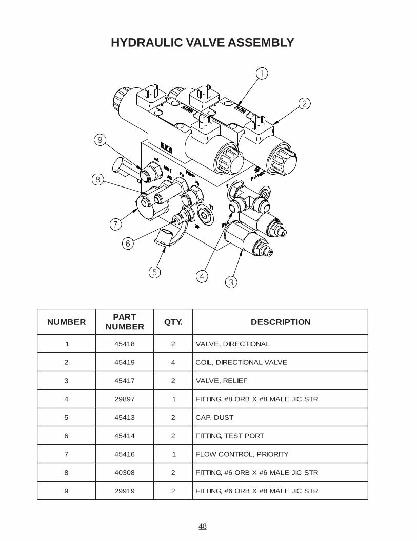
HYDRAULIC VALVE ASSEMBLY
REBMUNTRAP
REBMUN.YTQ NOITPIRCSED
1 81454 2 LANOITCERID,EVLAV
2 91454 4 EVLAVLANOITCERID,LIOC
3 71454 2 FEILER,EVLAV
4 79892 1 RTSCIJELAM8#XBRO8#.GNITTIF
5 31454 2 TSUD,PAC
6 41454 2 TROPTSET,GNITTIF
7 61454 1 YTIROIRP,LORTNOCWOLF
8 80304 2 RTSCIJELAM6#XBRO6#,GNITTIF
9 91992 2 RTSCIJELAM8#XBRO6#,GNITTIF
1
2
3
7
5
6
9
8
4
49
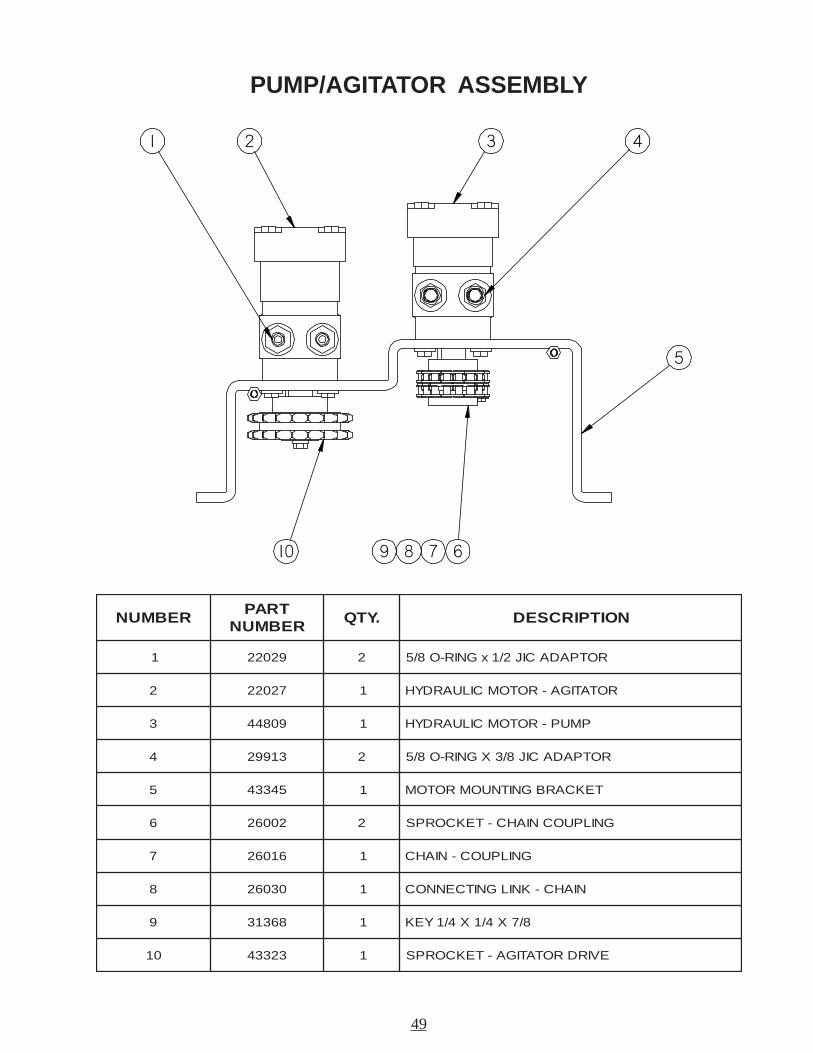
PUMP/AGITATOR ASSEMBLY
REBMUNTRAP
REBMUN.YTQ NOITPIRCSED
1 92022 2 ROTPADACIJ2/1xGNIR-O8/5
2 72022 1 ROTATIGA-ROTOMCILUARDYH
3 90844 1 PMUP-ROTOMCILUARDYH
4 31992 2 ROTPADACIJ8/3XGNIR-O8/5
5 54334 1 TEKCARBGNITNUOMROTOM
6 20062 2 GNILPUOCNIAHC-TEKCORPS
7 61062 1 GNILPUOC-NIAHC
8 03062 1 NIAHC-KNILGNITCENNOC
9 86313 1 8/7X4/1X4/1YEK
01 32334 1 EVIRDROTATIGA-TEKCORPS
1 2 3 4
5
67810 9
50
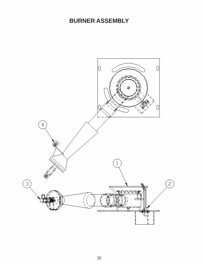
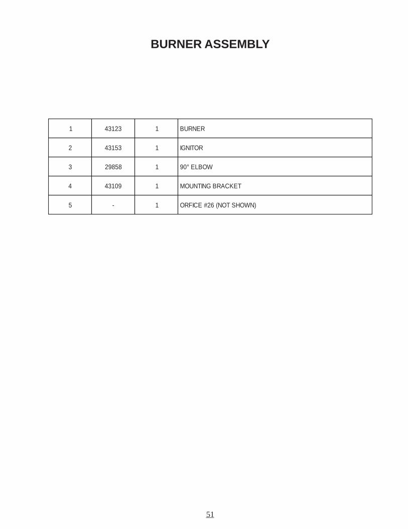
BURNER ASSEMBLY
51
BURNER ASSEMBLY
1 32134 1 RENRUB
2 35134 1 ROTINGI
3 85892 1 WOBLE°09
4 90134 1 TEKCARBGNITNUOM
5 - 1 )NWOHSTON(62#ECIFRO
52
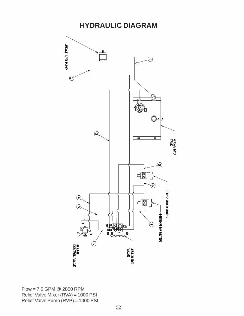
HYDRAULIC DIAGRAM
Flow = 7.0 GPM @ 2850 RPMRelief Valve Mixer (RVA) = 1000 PSIRelief Valve Pump (RVP) = 1000 PSI
53
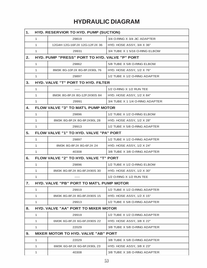
HYDRAULIC DIAGRAM
)NOITCUS(PMUP.DYHOTROIVRESER.DYH.1
1 91892 RETPADACIJ4/3XGNIR-O4/3
1 63XJF21-G21XJF61-G21H4G21 "63X4/3,.YSSAESOH.DYH
1 13992 WOBLEGNIR-O61/51XEBUT4/3
TROP"P"EVLAV.DYHOTTROP"SSERP"PMUP.DYH.2
1 26892 WOBLEGNIR-O8/5XEBUT8/5
1 67L09XJF8-G8XJF01-G8K3M8 "67X2/1,.YSSAESOH.DYH
1 79892 RETPADAGNIR-O2/1XEBUT2/1
RETLIF.DYHOTTROP"T"EVLAV.DYH.3
1 ----- EETNUR2/1XGNIR-O2/1
1 48S09XJF21-G8XJF8-G8K3M8 "48X2/1,.YSSAESOH.DYH
1 19992 RETPADAGNIR-O4/11XEBUT4/3
ROTOMPMUPL'TAMOT"3"EVLAVWOLF.4
1 69892 WOBLEGNIR-O2/1XEBUT2/1
1 82L09XJF8-G8XJF8-G8K3M8 "82X2/1,.YSSAESOH.DYH
1 31992 RETPADAGNIR-O8/5XEBUT2/1
TROP"AP"EVLAV.DYHOT"1"EVLAVWOLF.5
1 79892 RETPADAGNIR-O2/1XEBUT2/1
1 42XJF6-G8XJF8-G8K3M8 "42X2/1,.YSSAESOH.DYH
1 80304 RETPADAGNIR-O8/3XEBUT8/3
TROP"T"EVLAV.DYHOT"2"EVLAVWOLF.6
1 69892 WOBLEGNIR-O2/1XEBUT2/1
1 03S09XJF8-G8XJF8-G8K3M8 "03X2/1,.YSSAESOH.DYH
1 ----- EETNUR2/1XGNIR-O2/1
ROTOMPMUPL'TAMOTTROP"BP"EVLAV.DYH.7
1 91992 RETPADAGNIR-O2/1XEBUT2/1
1 51S09XJF8-G8XJF8-G8K3M8 "51X2/1,.YSSAESOH.DYH
1 31992 RETPADAGNIR-O8/5XEBUT2/1
ROTOMREXIMOTTROP"AA"EVLAV.DYH.8
1 91992 RETPADAGNIR-O2/1XEBUT2/1
1 22S09XJF6-G6XJF8-G6K3M6 "22X8/3,.YSSAESOH.DYH
1 92022 RETPADAGNIR-O8/5XEBUT8/3
TROP"BA"EVLAV.DYHOTROTOMREXIM.9
1 92022 RETPADAGNIR-O8/5XEBUT8/3
1 32L09XJF6-G6XJF6-G6K3M6 "32X8/3,.YSSAESOH.DYH
1 80304 RETPADAGNIR-O8/3XEBUT8/3
54
LPG SCHEMATIC
55
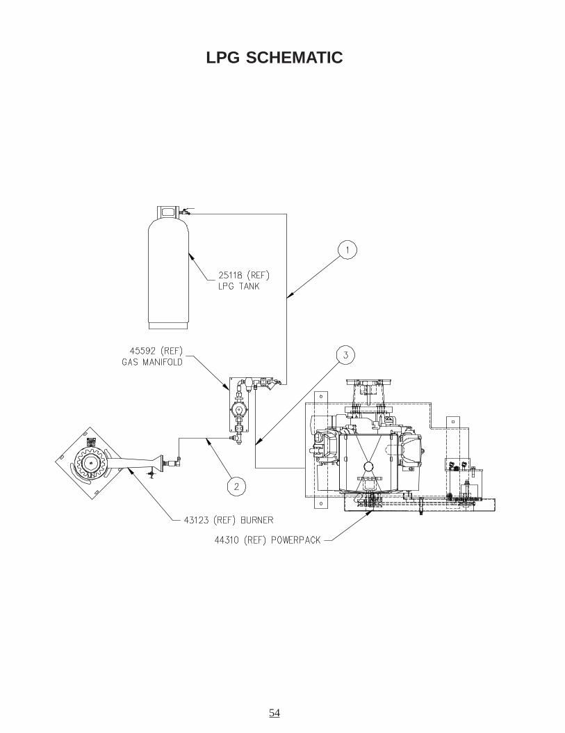
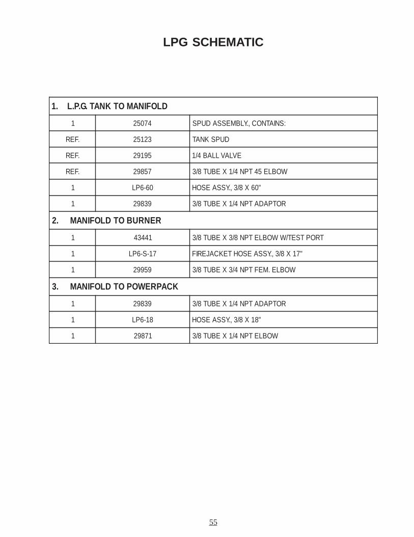
LPG SCHEMATIC
DLOFINAMOTKNAT.G.P.L.1
1 47052 :SNIATNOC,.YLBMESSADUPS
.FER 32152 DUPSKNAT
.FER 59192 EVLAVLLAB4/1
.FER 75892 WOBLE54TPN4/1XEBUT8/3
1 06-6PL "06X8/3,.YSSAESOH
1 93892 ROTPADATPN4/1XEBUT8/3
RENRUBOTDLOFINAM.2
1 14434 TROPTSET/WWOBLETPN8/3XEBUT8/3
1 71-S-6PL "71X8/3,.YSSAESOHTEKCAJERIF
1 95992 WOBLE.MEFTPN4/3XEBUT8/3
KCAPREWOPOTDLOFINAM.3
1 93892 ROTPADATPN4/1XEBUT8/3
1 81-6PL "81X8/3,.YSSAESOH
1 17892 WOBLETPN4/1XEBUT8/3
ELECTRICAL SCHEMATIC
56
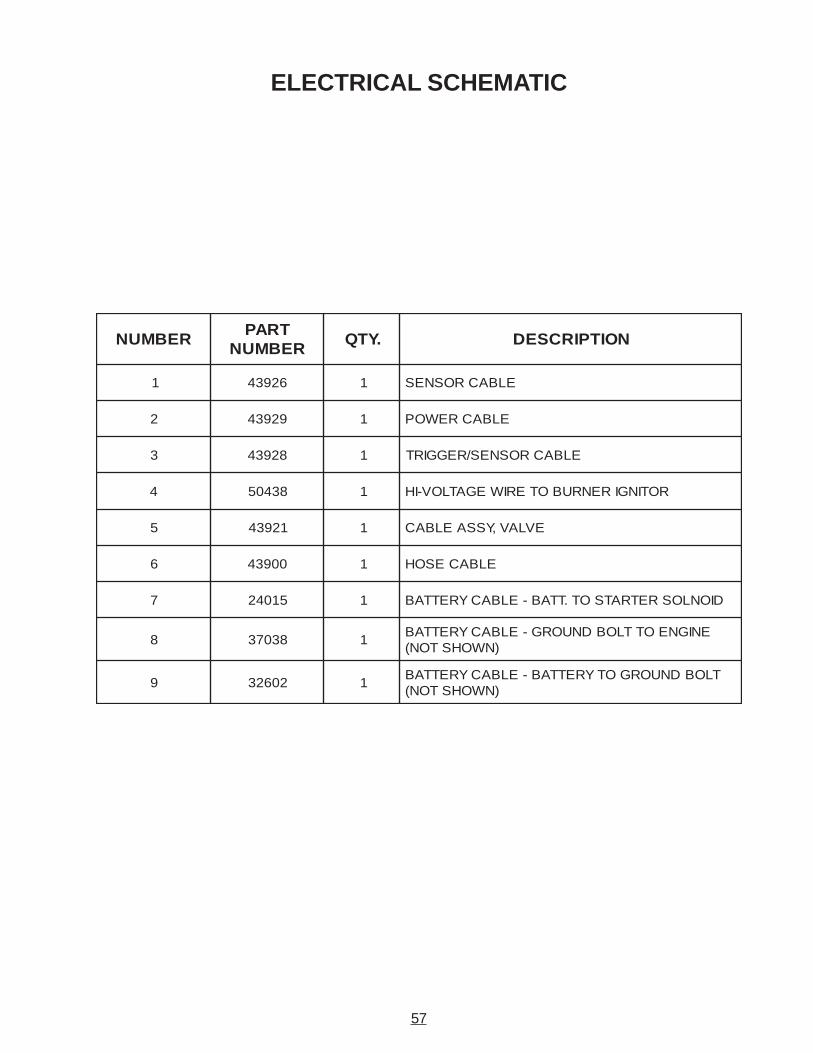
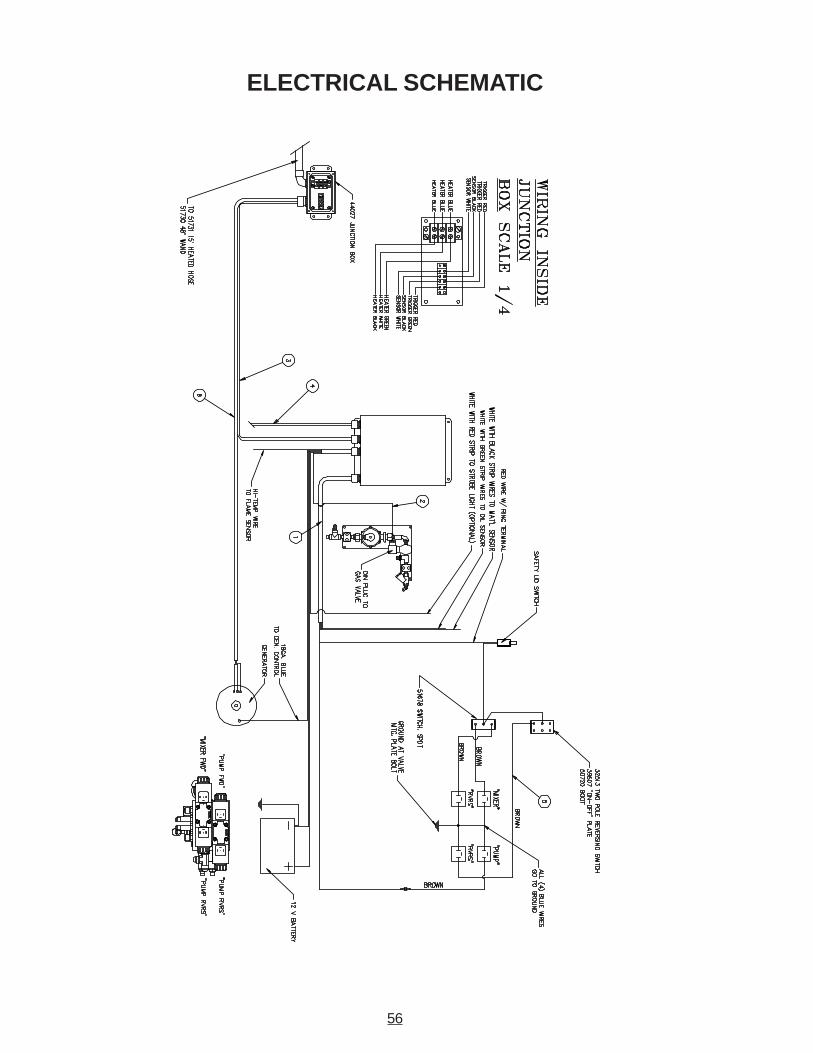
ELECTRICAL SCHEMATIC
REBMUNTRAP
REBMUN.YTQ NOITPIRCSED
1 62934 1 ELBACROSNES
2 92934 1 ELBACREWOP
3 82934 1 ELBACROSNES/REGGIRT
4 83405 1 ROTINGIRENRUBOTERIWEGATLOV-IH
5 12934 1 EVLAV,YSSAELBAC
6 00934 1 ELBACESOH
7 51042 1 DIONLOSRETRATSOT.TTAB-ELBACYRETTAB
8 83073 1ENIGNEOTTLOBDNUORG-ELBACYRETTAB
)NWOHSTON(
9 20623 1TLOBDNUORGOTYRETTAB-ELBACYRETTAB
)NWOHSTON(
57
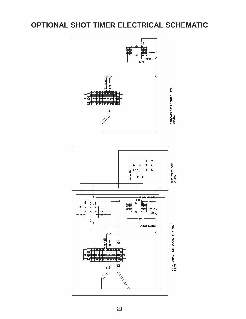
OPTIONAL SHOT TIMER ELECTRICAL SCHEMATIC
58


©Copyright 2002 by Crafco, Inc.
Recommended