1www.sullinscorp.com | 760-744-0125 | toll-free 888-774-3100 | fax 760-744-6081 | [email protected]
QUICK QUOTESOur customer-driven sales team will provide quotes quickly, usually within hours of being contacted. Our aim is to provide you with pricing information fast, so you can place your order and receive it on time.
CUSTOM CONNECTORSWhether your next design requires a unique connector or just something simple like a molded-in key, Sullins is ready to provide you with a solution to your particular design challenge. We can design a custom connector for your project with little or no additional cost. Call our sales team today and experience the Sullins Advantage. And, since we manufacture most of our connectors in California, we can usually have a custom product ready in just days.
FREE CONSULTATIONOur engineering and technical teams are experts in edgecard connector and header design. We can help with engineering consultation for a variety of connector applications and a broad range of products. Call us and utilize our technical resources on your next design.
QUICK TURNAROUNDYour project is important to us, so fast delivery is our primary goal. Our average lead times are less than fi ve days, and many orders ship the same day. We strive to provide you with the best quality products in record time. Great products, delivered fast! Our goal is to keep your project on track.
EASY PRODUCT SEARCHReturning customer? Quickly fi nd a product by part number by using our index on pages 127 - 131.
WE VALUE YOUR BUSINESS
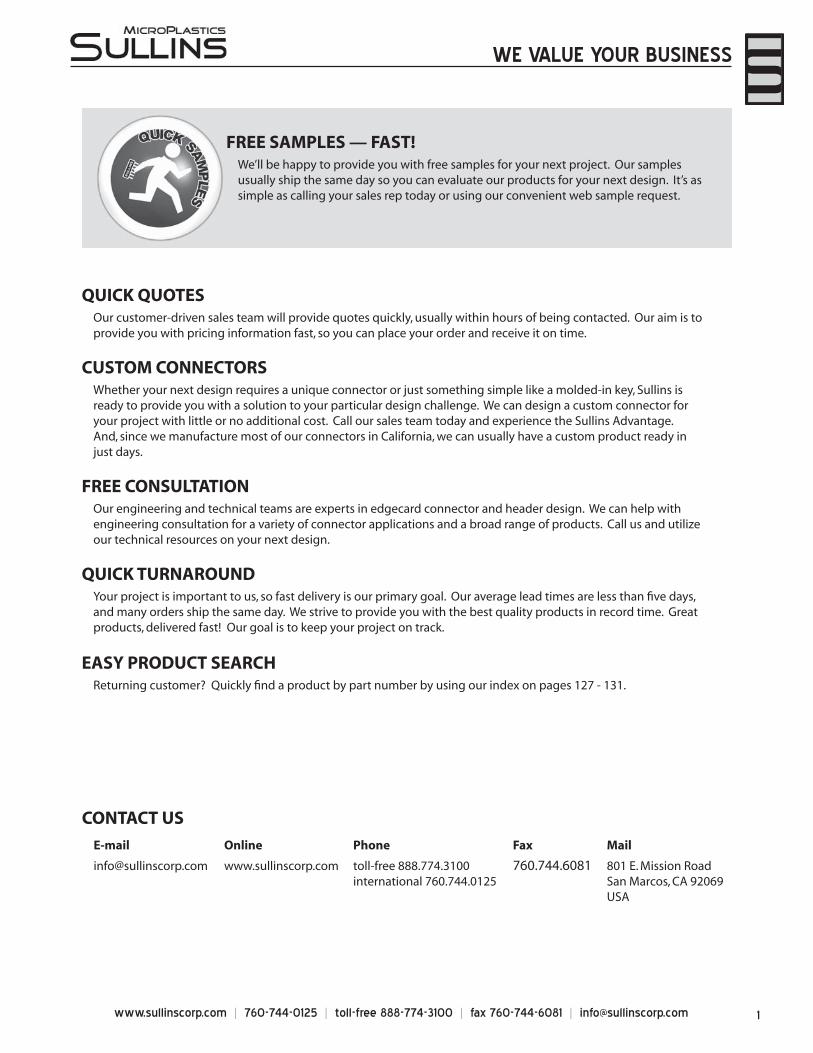
FREE SAMPLES — FAST!We’ll be happy to provide you with free samples for your next project. Our samples usually ship the same day so you can evaluate our products for your next design. It’s as simple as calling your sales rep today or using our convenient web sample request.
CONTACT US
Online
www.sullinscorp.com
Phone
toll-free 888.774.3100international 760.744.0125
Fax
760.744.6081
801 E. Mission RoadSan Marcos, CA 92069USA
www.sullinscorp.com | 760-744-0125 | toll-free 888-774-3100 | fax 760-744-6081 | [email protected]
Sullins EdgecardsGENERAL SPECIFICATIONS . . . . . . . . . . . . . . . . . . . . . . . . . . . . . . . . . . . . . . . . . . . . . . . . . . . . . . . . . . . . . . . . . . . . . . . . . . . . . . . . . . . . . . . . . . . . . . . . . . . . . . . . . . . . . .4
PART NUMBER OPTIONS . . . . . . . . . . . . . . . . . . . . . . . . . . . . . . . . . . . . . . . . . . . . . . . . . . . . . . . . . . . . . . . . . . . . . . . . . . . . . . . . . . . . . . . . . . . . . . . . . . . . . . . . . . . . . . . . .5
1.00 mm [.039” ] Contact Centers15.49 mm Profi le, Dip Solder/Card Extender/SMT . . . . . . . . . . . . . . . . . . . . . . . . . . . . . . . . . . . . . . . . . . . . . . . . . . . . . . . . . . . . . . . . . . . . . . . . . . . . . . . . . . .6
21.84 mm Profi le, Right Angle . . . . . . . . . . . . . . . . . . . . . . . . . . . . . . . . . . . . . . . . . . . . . . . . . . . . . . . . . . . . . . . . . . . . . . . . . . . . . . . . . . . . . . . . . . . . . . . . . . .8
15.49 mm PCI Express Dip Solder . . . . . . . . . . . . . . . . . . . . . . . . . . . . . . . . . . . . . . . . . . . . . . . . . . . . . . . . . . . . . . . . . . . . . . . . . . . . . . . . . . . . . .10
15.49 mm PCI Express Card Extender for Straddle Mount . . . . . . . . . . . . . . . . . . . . . . . . . . . . . . . . . . . . . . . . . . . . . . . . . . . . . . . . . . . . . . . . . . . . . . . . . . . . . .12
.050” [1.27 mm] Contact Centers
.610” Profi le, Dip Solder/Card Extender/SMT . . . . . . . . . . . . . . . . . . . . . . . . . . . . . . . . . . . . . . . . . . . . . . . . . . . . . . . . . . . . . . . . . . . . . . . . . . . . . . . . . . . . . . . .14
.915” Profi le, Right Angle . . . . . . . . . . . . . . . . . . . . . . . . . . . . . . . . . . . . . . . . . . . . . . . . . . . . . . . . . . . . . . . . . . . . . . . . . . . . . . . . . . . . . . . . . . . . . . . . . . . .16
.610” Profi le, [MCA] Dip Solder/Card Extender/SMT . . . . . . . . . . . . . . . . . . . . . . . . . . . . . . . . . . . . . . . . . . . . . . . . . . . . . . . . . . . . . . . . . . . . . . . . . . . . . . . .18
.915” Profi le, [MCA] Right Angle . . . . . . . . . . . . . . . . . . . . . . . . . . . . . . . . . . . . . . . . . . . . . . . . . . . . . . . . . . . . . . . . . . . . . . . . . . . . . . . . . . . . . . . . . . . . . . . . . . . . . . .20
.610” Profi le, [PCI] Dip Solder/Card Extender/SMT . . . . . . . . . . . . . . . . . . . . . . . . . . . . . . . . . . . . . . . . . . . . . . . . . . . . . . . . . . . . . . . . . . . . . . . . . . . . . . . . . .22
.915” Profi le, [PCI] Right Angle . . . . . . . . . . . . . . . . . . . . . . . . . . . . . . . . . . . . . . . . . . . . . . . . . . . . . . . . . . . . . . . . . . . . . . . . . . . . . . . . . . . . . . . . . . . . . . . . . . . . . . . .24
Bi-Level, .050” [1.27 mm] / .100” [2.54 mm] Contact CentersBi-Level, High Density, Card Extender, Dip Solder . . . . . . . . . . . . . . . . . . . . . . . . . . . . . . . . . . . . . . . . . . . . . . . . . . . . . . . . . . . . . . . . . . . . . . . . . . . . . . . . . .26
Bi-Level, High Density, Right Angle . . . . . . . . . . . . . . . . . . . . . . . . . . . . . . . . . . . . . . . . . . . . . . . . . . . . . . . . . . . . . . . . . . . . . . . . . . . . . . . . . . . . . . . . . . . . . . . . . . .28
Male Edgecards, .100” [2.54 mm] Contact Centers.540” Profi le, Male Edgecard, Dip Solder/Right Angle/Card Extender . . . . . . . . . . . . . . . . . . . . . . . . . . . . . . . . . . . . . . . . . . . . . . . . . . . . . . . . . . . . 30
.100” [2.54 mm] Contact Centers
.431” Profi le, Dip Solder/Eyelet/Right Angle for .062”[1.57] or .031”[0.79] Mating PCB . . . . . . . . . . . . . . . . . . . . . . . . . . . . . . . . . . . . . . . .32
.431” Profi le, Dip Solder/Eyelet/Right Angle for .093”[2.36] Mating PCB . . . . . . . . . . . . . . . . . . . . . . . . . . . . . . . . . . . . . . . . . . . . . . . . . . . . . . . .34
.550” or .610” Profi le, Press Fit . . . . . . . . . . . . . . . . . . . . . . . . . . . . . . . . . . . . . . . . . . . . . . . . . . . . . . . . . . . . . . . . . . . . . . . . . . . . . . . . . . . . . . . . . . . . . . . . . . . . . . . . .36
.610” Profi le, Dip Solder/Wire Wrap/Right Angle/Card Extender . . . . . . . . . . . . . . . . . . . . . . . . . . . . . . . . . . . . . . . . . . . . . . . . . . . . . . . . . . . . . . . . .38
.610” Profi le, Dip Solder/Wire Wrap/Right Angle for .093”[2.36] or .125”[3.18] Mating PCB . . . . . . . . . . . . . . . . . . . . . . . . . . . . . . . . . . .40
.610” Profi le, .400” Wide Body for .093”[2.36] Mating PCB, Dip Solder/Wire Wrap/Right Angle/Card Extender . . . . . . . . . . . . .42
.610” Profi le, Dip Solder/ Wire Wrap/Right Angle [ISA] . . . . . . . . . . . . . . . . . . . . . . . . . . . . . . . . . . . . . . . . . . . . . . . . . . . . . . . . . . . . . . . . . . . . . . . . . . . . .44
.690” Profi le, Make Before Break Dip Solder/Card Extender/Right Angle . . . . . . . . . . . . . . . . . . . . . . . . . . . . . . . . . . . . . . . . . . . . . . . . . . . . . . . .46
.125” [3.18 mm] Contact Centers
.431” Profi le, Dip Solder/Eyelet/Right Angle for .062”[1.57] or .031”[0.79] Mating PCB . . . . . . . . . . . . . . . . . . . . . . . . . . . . . . . . . . . . . . . .48
.610” Profi le, Dip Solder/Wire Wrap/Right Angle . . . . . . . . . . . . . . . . . . . . . . . . . . . . . . . . . . . . . . . . . . . . . . . . . . . . . . . . . . . . . . . . . . . . . . . . . . . . . . . . . . . .50
.610” Profi le, Dip Solder/Wire Wrap/Right Angle for .093”[2.36] or .125”[3.18] Mating PCB . . . . . . . . . . . . . . . . . . . . . . . . . . . . . . . . . .52
.150” [3.81 mm] Contact Centers
.550” Profi le, Dip Solder/Wire Wrap . . . . . . . . . . . . . . . . . . . . . . . . . . . . . . . . . . . . . . . . . . . . . . . . . . . . . . . . . . . . . . . . . . . . . . . . . . . . . . . . . . . . . . . . . . . . . . . . . . .54
Bi-Level, .078” [1.98 mm] / .156” [3.96 mm] Contact CentersBi-Level, High Density, Right Angle . . . . . . . . . . . . . . . . . . . . . . . . . . . . . . . . . . . . . . . . . . . . . . . . . . . . . . . . . . . . . . . . . . . . . . . . . . . . . . . . . . . . . . . . . . . . . . . . . . .56
.156” [3.96mm] Contact Centers
.431” Profi le, Dip Solder/Eyelet/Right Angle . . . . . . . . . . . . . . . . . . . . . . . . . . . . . . . . . . . . . . . . . . . . . . . . . . . . . . . . . . . . . . . . . . . . . . . . . . . . . . . . . . . . . . . . .58
.431” Profi le, Special Body Confi guration, Dip Solder/Eyelet/Right Angle . . . . . . . . . . . . . . . . . . . . . . . . . . . . . . . . . . . . . . . . . . . . . . . . . . . . . . .60
.610” Profi le, Dip Solder/Wire Wrap/Right Angle . . . . . . . . . . . . . . . . . . . . . . . . . . . . . . . . . . . . . . . . . . . . . . . . . . . . . . . . . . . . . . . . . . . . . . . . . . . . . . . . . . . .62
.610” Profi le, Dip Solder/Wire Wrap/Right Angle for .093”[2.36] or .125”[3.18] Mating PCB . . . . . . . . . . . . . . . . . . . . . . . . . . . . . . . . . . .64
.720” Profi le, .045” sq../.031” x .062” Wire Wrap/Dip Solder . . . . . . . . . . . . . . . . . . . . . . . . . . . . . . . . . . . . . . . . . . . . . . . . . . . . . . . . . . . . . . . . . . . . . . . . .66
.720” Profi le, .045” sq. Make Before Break Wire Wrap . . . . . . . . . . . . . . . . . . . . . . . . . . . . . . . . . . . . . . . . . . . . . . . . . . . . . . . . . . . . . . . . . . . . . . . . . . . . . . .68
TABLE OF CONTENTS
3www.sullinscorp.com | 760-744-0125 | toll-free 888-774-3100 | fax 760-744-6081 | [email protected]
Sullins Headers
.050” [1.27 mm] Contact Centers
.050” [1.27mm] Contact Centers, Male Header . . . . . . . . . . . . . . . . . . . . . . . . . . . . . . . . . . . . . . . . . . . . . . . . . . . . . . . . . . . . . . . . . . . . . . . . . . . . . . . . . . . . . .70
.050”[1.27mm] Contact Centers, Female Header . . . . . . . . . . . . . . . . . . . . . . . . . . . . . . . . . . . . . . . . . . . . . . . . . . . . . . . . . . . . . . . . . . . . . . . . . . . . . . . . . . .72
.079” [2.00 mm] Contact Centers
.079” [2mm] Contact Centers, Male Header . . . . . . . . . . . . . . . . . . . . . . . . . . . . . . . . . . . . . . . . . . . . . . . . . . . . . . . . . . . . . . . . . . . . . . . . . . . . . . . . . . . . . . . . .74
.079”[2mm] Contact Centers, Female Header . . . . . . . . . . . . . . . . . . . . . . . . . . . . . . . . . . . . . . . . . . . . . . . . . . . . . . . . . . . . . . . . . . . . . . . . . . . . . . . . . . . . . . .76
.100” [2.54 mm] Contact Centers
.100” [2.54mm] Contact Centers, Male Breakaway Header . . . . . . . . . . . . . . . . . . . . . . . . . . . . . . . . . . . . . . . . . . . . . . . . . . . . . . . . . . . . . . . . . . . . . . . .78
.100” [2.54 mm] Contact Centers, Female Header . . . . . . . . . . . . . . . . . . . . . . . . . . . . . . . . . . . . . . . . . . . . . . . . . . . . . . . . . . . . . . . . . . . . . . . . . . . . . . . . . .80
Micro Plastics Edgecards
GENERAL SPECIFICATIONS . . . . . . . . . . . . . . . . . . . . . . . . . . . . . . . . . . . . . . . . . . . . . . . . . . . . . . . . . . . . . . . . . . . . . . . . . . . . . . . . . . . . . . . . . . . . . . . . . . . . . . . . . . . .82
PART NUMBER OPTIONS . . . . . . . . . . . . . . . . . . . . . . . . . . . . . . . . . . . . . . . . . . . . . . . . . . . . . . . . . . . . . . . . . . . . . . . . . . . . . . . . . . . . . . . . . . . . . . . . . . . . . . . . . . . . . . . .83
.100” [2.54 mm] Contact Centers
.431” Profi le, Dip Solder . . . . . . . . . . . . . . . . . . . . . . . . . . . . . . . . . . . . . . . . . . . . . . . . . . . . . . . . . . . . . . . . . . . . . . . . . . . . . . . . . . . . . . . . . . . . . . . . . . . . . . . . . . . . . . . .84
.431” Profi le, Card Extender . . . . . . . . . . . . . . . . . . . . . . . . . . . . . . . . . . . . . . . . . . . . . . . . . . . . . . . . . . . . . . . . . . . . . . . . . . . . . . . . . . . . . . . . . . . . . . . . . . . . . . . . . . . .86
.431” Profi le, Eyelet . . . . . . . . . . . . . . . . . . . . . . . . . . . . . . . . . . . . . . . . . . . . . . . . . . . . . . . . . . . . . . . . . . . . . . . . . . . . . . . . . . . . . . . . . . . . . . . . . . . . . . . . . . . . . . . . . . . . .88
.610” Profi le, Wire Wrap & Dip Solder . . . . . . . . . . . . . . . . . . . . . . . . . . . . . . . . . . . . . . . . . . . . . . . . . . . . . . . . . . . . . . . . . . . . . . . . . . . . . . . . . . . . . . . . . . . . . . . .90
.550” Profi le, .025” Square Card Extender . . . . . . . . . . . . . . . . . . . . . . . . . . . . . . . . . . . . . . . . . . . . . . . . . . . . . . . . . . . . . . . . . . . . . . . . . . . . . . . . . . . . . . . . . . . .92
.610” Profi le, Right Angle . . . . . . . . . . . . . . . . . . . . . . . . . . . . . . . . . . . . . . . . . . . . . . . . . . . . . . . . . . . . . . . . . . . . . . . . . . . . . . . . . . . . . . . . . . . . . . . . . . . . . . . . . . . . . . .94
.610” Profi le, Special 18/31 with Barrier, Dip Solder/ Wire Wrap [ISA] . . . . . . . . . . . . . . . . . . . . . . . . . . . . . . . . . . . . . . . . . . . . . . . . . .96
.125” [3.18 mm] Contact Centers
.431” Profi le, Dip Solder . . . . . . . . . . . . . . . . . . . . . . . . . . . . . . . . . . . . . . . . . . . . . . . . . . . . . . . . . . . . . . . . . . . . . . . . . . . . . . . . . . . . . . . . . . . . . . . . . . . . . . . . . . . . . . . .98
.431” Profi le, Card Extender . . . . . . . . . . . . . . . . . . . . . . . . . . . . . . . . . . . . . . . . . . . . . . . . . . . . . . . . . . . . . . . . . . . . . . . . . . . . . . . . . . . . . . . . . . . . . . . . . . . . . . . . . . . .100
.431” Profi le, Eyelet . . . . . . . . . . . . . . . . . . . . . . . . . . . . . . . . . . . . . . . . . . . . . . . . . . . . . . . . . . . . . . . . . . . . . . . . . . . . . . . . . . . . . . . . . . . . . . . . . . . . . . . . . . . . . . . . . . . . 102
.610” Profi le, Wire Wrap & Dip Solder . . . . . . . . . . . . . . . . . . . . . . . . . . . . . . . . . . . . . . . . . . . . . . . . . . . . . . . . . . . . . . . . . . . . . . . . . . . . . . . . . . . . . . . . . . . . . . .104
.550” Profi le, .025” Square Card Extender . . . . . . . . . . . . . . . . . . . . . . . . . . . . . . . . . . . . . . . . . . . . . . . . . . . . . . . . . . . . . . . . . . . . . . . . . . . . . . . . . . . . . . . . . . .106
.610” Profi le, Right Angle . . . . . . . . . . . . . . . . . . . . . . . . . . . . . . . . . . . . . . . . . . . . . . . . . . . . . . . . . . . . . . . . . . . . . . . . . . . . . . . . . . . . . . . . . . . . . . . . . . . . . . . . . . . . .108
.150” [3.81 mm] Contact Centers
.550” Profi le, .025” Square & .026” Round Dip Solder . . . . . . . . . . . . . . . . . . . . . . . . . . . . . . . . . . . . . . . . . . . . . . . . . . . . . . . . . . . . . . . . . . . . . . . . . . . . .110
.156” [3.96 mm] Contact Centers
.431” Profi le, Dip Solder . . . . . . . . . . . . . . . . . . . . . . . . . . . . . . . . . . . . . . . . . . . . . . . . . . . . . . . . . . . . . . . . . . . . . . . . . . . . . . . . . . . . . . . . . . . . . . . . . . . . . . . . . . . . . .112
.431” Profi le, Card Extender . . . . . . . . . . . . . . . . . . . . . . . . . . . . . . . . . . . . . . . . . . . . . . . . . . . . . . . . . . . . . . . . . . . . . . . . . . . . . . . . . . . . . . . . . . . . . . . . . . . . . . . . . .114
.431” Profi le, Eyelet . . . . . . . . . . . . . . . . . . . . . . . . . . . . . . . . . . . . . . . . . . . . . . . . . . . . . . . . . . . . . . . . . . . . . . . . . . . . . . . . . . . . . . . . . . . . . . . . . . . . . . . . . . . . . . . . . . . .116
.610” Profi le, Wire Wrap & Dip Solder . . . . . . . . . . . . . . . . . . . . . . . . . . . . . . . . . . . . . . . . . . . . . . . . . . . . . . . . . . . . . . . . . . . . . . . . . . . . . . . . . . . . . . . . . . . . . . .118
.550” Profi le, .025” Square Card Extender . . . . . . . . . . . . . . . . . . . . . . . . . . . . . . . . . . . . . . . . . . . . . . . . . . . . . . . . . . . . . . . . . . . . . . . . . . . . . . . . . . . . . . . . . . .120
.610” Profi le, Right Angle . . . . . . . . . . . . . . . . . . . . . . . . . . . . . . . . . . . . . . . . . . . . . . . . . . . . . . . . . . . . . . . . . . . . . . . . . . . . . . . . . . . . . . . . . . . . . . . . . . . . . . . . . . . . .122
.720” Profi le, .045” Square Wire Wrap . . . . . . . . . . . . . . . . . . . . . . . . . . . . . . . . . . . . . . . . . . . . . . . . . . . . . . . . . . . . . . . . . . . . . . . . . . . . . . . . . . . . . . . . . . . . . . . .124
Polarizing KeysPolarizing Keys, In Between Contact & In Contact . . . . . . . . . . . . . . . . . . . . . . . . . . . . . . . . . . . . . . . . . . . . . . . . . . . . . . . . . . . . . . . . . . . . . . . . . . . . . . . .126
Part Number Index . . . . . . . . . . . . . . . . . . . . . . . . . . . . . . . . . . . . . . . . . . . . . . . . . . . . . . . . . . . . . . . . . . . . . . . . . . . . . . . . . . . . . . . . . . . . . . . . . . . . . . . . . . . . .127
TABLE OF CONTENTS
www.sullinscorp.com | 760-744-0125 | toll-free 888-774-3100 | fax 760-744-6081 | [email protected]
Sullins EdgecardsSu
llins
Edg
ecar
ds
GENERAL SPECIFICATIONS
MATERIALS Insulator
• PBT, Valox*, Thermoplastic Polyester • PPS, Ryton*, Polyphenylene Sulfi de • PEEK, Polyetheretherketone• PA9T, High Temperature Polyamide • Other materials available. Consult Factory
Contacts Phosphor Bronze (Standard), Beryllium Copper, Beryllium Nickel, Spinodal**, Brass
Plating Gold and/or Tin over .000050” Nickel Underplate, Lead Free
UL/CUL File Number: E64287
Cage Code: 54453
ENVIRONMENTAL Solvent resistance: Perchloroethylene, Freon 113, Freon 11, Trichloroethylene
Operating Temperature: PBT -650 to +1300C Phosphor Bronze -650 to +1250CPPS -650 to +200/2200C*** Beryllium Copper -650 to +1500C
PEEK -650 to +2500C*** Spinodal** -650 to +2000CPA9T -650 to +1500C Beryllium Nickel*** -650 to +3000C(Continuous temperatures, higher for short duration. Contact Factory for details.)
ELECTRICAL Insulation Resistance: 5,000 Mega Ohm
Dielectric Withstanding Voltage
Contact Centers: .039”[1mm] .050”[1.27mm] .100”[2.54mm] .125”[3.18mm] .150”[3.81mm] .156”[3.96mm]Voltage: 125 VDC 250 VDC 600 VDC 800 VDC 1500 VDC 1800 VDC
225 VAC 300 VAC 750 VAC 750 VAC 900 VAC 950 VAC Current Rating: 1 to 5 amp per contact Voltage Drop: 30 milli volt at rated current Contact Resistance: 30 milli ohm maximum at rated current
MECHANICAL Board Insertion Force 16 oz Maximum per contact pair using .062”[1.58mm] thick steel test blade Board Withdrawal Force 1 oz Minimum per contact pair using .062”[1.58mm] thick steel test blade Special Insertion/Withdrawal forces available upon request
* Or equivalent.** Consult factory for special soldering guidelines.
*** Consult factory.
All parts are currently manufactured with recommended materials to meet RoHS standards. All contacts have 50u” of nickel underplating, and a large selection of plating options: Pure tin matte, overall gold, or selective gold plating. For complete part number information or operating/processing temperature parameters, visit the RoHS section of our website, or refer to page 5 of this catalog.
RoHS COMPLIANT
5www.sullinscorp.com | 760-744-0125 | toll-free 888-774-3100 | fax 760-744-6081 | [email protected]
Sullins EdgecardsSullins Edgecards
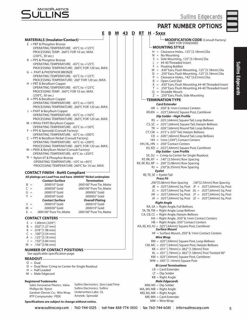
PART NUMBER OPTIONS
MATERIALS (Insulator/Contact)
CONTACT CENTERSE = 1.00mm [.039”]B = .050” [1.27 mm]K = .078” [1.98 mm]C = .100” [2.54 mm]A = .125” [3.18 mm]J = .150” [3.84 mm]
M = .156” [3.96 mm]
NUMBER OF CONTACT POSITIONSSee applicable specification page
READOUTD = DualD = Dual Row/ Crimp to Center for Single ReadoutH = Half LoadedM = Male Edgecard
MOUNTING STYLEH = Clearance Holes, .125” [3.18mm] DiaN = No MountingS = Side Mounting, .125” [3.18mm] DiaI = #4-40 Threaded InsertF = Floating Bobbin
W = .430” Ears, Flush Mounting, .125” [3.18mm] DiaD = .250” Ears, Flush Mounting, .125” [3.18mm] DiaP = Clearance Holes, .142” [3.61mm] Dia.B = Open Card SlotX = .430” Ears, Flush Mounting, #4-40 Threaded InsertT = .250” Ears, Flush Mounting, #4-40 Threaded InsertQ = Straddle MountZ = .250” Ears, Flush, Side Mounting
TERMINATION TYPECard Extender
HR = .050” & 1mm Contact Centers KR,KN = .025”[.64mm] Square Post, Cantilever
Dip Solder - High ProfileRS = .025 [.64mm] Square Tail, Loop Bellows
CS, SC = .025” [.64mm] Square Tail, Hairpin BellowsTK = .026” [.66mm] Round Tail, Loop Bellows
CT, CW = .015” x .025” Tail, Hairpin BellowsCK = .026” [.66mm] Round Tail, Loop BellowsHH = 1mm [.039”] Contact Centers
HH, HL, HN = .050” Contact Centers KS, KD = .025”[.64mm] Square Post, Cantilever
Dip Solder - Low ProfileSX, SU = Crimp to Center for Single Readout
RT, RK, RY = .140” [3.56mm] Row SpacingRX, RF, RU, RP = .200” [5.08mm] Row Spacing
RJ = .250”[6.35mm] Row SpacingEyelet
RE, TE, SE = Eyelet Tail
Right AngleRA, SA = Right Angle, Full Bellows
TA, TB, TM = Right Angle, Loop BellowsCA, CB, CC = Right Angle, Hairpin Bellows
HA = Right Angle, .050” & 1mm Contact CentersHB = Right Angle, .050” Contact Centers
KA, KE, KU, KJ = .025”[.64mm] Square Post, CantileverSurface Mount
HF = Surface Mount, .050” & 1mm Contact CentersWire Wrap
RM = .025”[.64mm] Square Post, Loop BellowsCM, MC = .025” [.64mm] Square Post, Hairpin Bellows
KK = .031” [.79mm] x .062” [1.58mm] PostKL = .031” [.79mm] x .062” [1.58mm] Post Twisted 90°
KM = .025”[.64mm] Square Post, CantileverWW = .045” [1.14mm] Square Post
Bi-Level TerminationsLR = Card ExtenderLT = Dip SolderKB = Right Angle
Press Fit.200”[5.08mm] Row Spacing .100”[2.54mm] Row Spacing
JB = .025”[.64mm] Sq. Post JF = .025”[.64mm] Sq. PostJC = .025”[.64mm] Sq. Post JG = .025”[.64mm] Sq. Post
JW = .025”[.64mm] Sq. Post JY = .025”[.64mm] Sq. PostJX = .025”[.64mm] Sq. Post JZ = .025”[.64mm] Sq. Post
MODIFICATION CODE (Consult Factory) OMIT FOR STANDARD
Registered Trademarks Sabic Innovative Plastics: Valox Phillips 66: Ryton Gardner-Denver Co.: Wire Wrap RTP Compounder: PEEK
Sullins Electronics: Zero Lead Time Sullins Electronics: Sullins Underwriters Labs: UL Ametek: Spinodal
Specifications are subject to change without notice.
E = PBT & Phosphor BronzeOPERATING TEMPERATURE: -65°C to +125°CPROCESSING TEMP: 260°C FOR 10 sec. MAX.(230°C, 30 sec.)
R = PPS & Phosphor BronzeOPERATING TEMPERATURE: -65°C to +125°CPROCESSING TEMPERATURE: 260°C FOR 120 sec. MAX.
G = PA9T & PHOSPHOR BRONZEOPERATING TEMPERATURE: -65°C to +125°CPROCESSING TEMPERATURE: 260° FOR 120 sec. MAX .
H = PBT & Beryllium CopperOPERATING TEMPERATURE: -65°C to +125°CPROCESSING TEMP: 260°C FOR 10 sec. MAX. (230°C, 30 sec.)
A = PPS & Beryllium CopperOPERATING TEMPERATURE: -65°C to +150°C PROCESSING TEMPERATURE: 260°C FOR 120 sec. MAX.
J = PA9T & Beryllium CopperOPERATING TEMPERATURE: -65°C to +150°CPROCESSING TEMPERATURE: 260°C FOR 120 sec. MAX.
M = White PA9T/Beryllium CopperOPERATING TEMPERATURE: -65°C to +150°C
F = PPS & Spinodal (Consult Factory)OPERATING TEMPERATURE: -65°C to +200°C
C = PPS & Beryllium Nickel (Consult Factory)OPERATING TEMPERATURE: -65°C to +200°CPROCESSING TEMPERATURE: 260°C FOR 120 sec. MAX.
W = PEEK & Beryllium Nickel (Consult Factory)OPERATING TEMPERATURE: -65°C to +250°C
N = Nylon 6T & Phosphor BronzeOPERATING TEMPERATURE: -100C to +850C PROCESSING TEMPERATURE: 2600C for 10 sec. MAX.
E B M 43 D RT H - Sxxx
CONTACT FINISH - RoHS CompliantAll platings are Lead Free and have .000050” Nickel underplate
Contact Surface TerminationB = .000010” Gold .000100” Pure Tin, MatteC = .000030” Gold .000100” Pure Tin, MatteG = .000010” Gold .000005” GoldY = .000030” Gold .000005” Gold
Contact Surface Overall PlatingS = .000010” Gold .000010” GoldM = .000030” Gold .000010” GoldE = .000100” Pure Tin, Matte .000100” Pure Tin, Matte
Male EdgecardsMW, MS = Dip Solder
MA, MV, MB = Right AngleMD, MJ, MK = Right Angle
MR, MN = Card ExtenderMM = Wire Wrap
www.sullinscorp.com | 760-744-0125 | toll-free 888-774-3100 | fax 760-744-6081 | [email protected]
Sullins EdgecardsSu
llins
Edg
ecar
ds
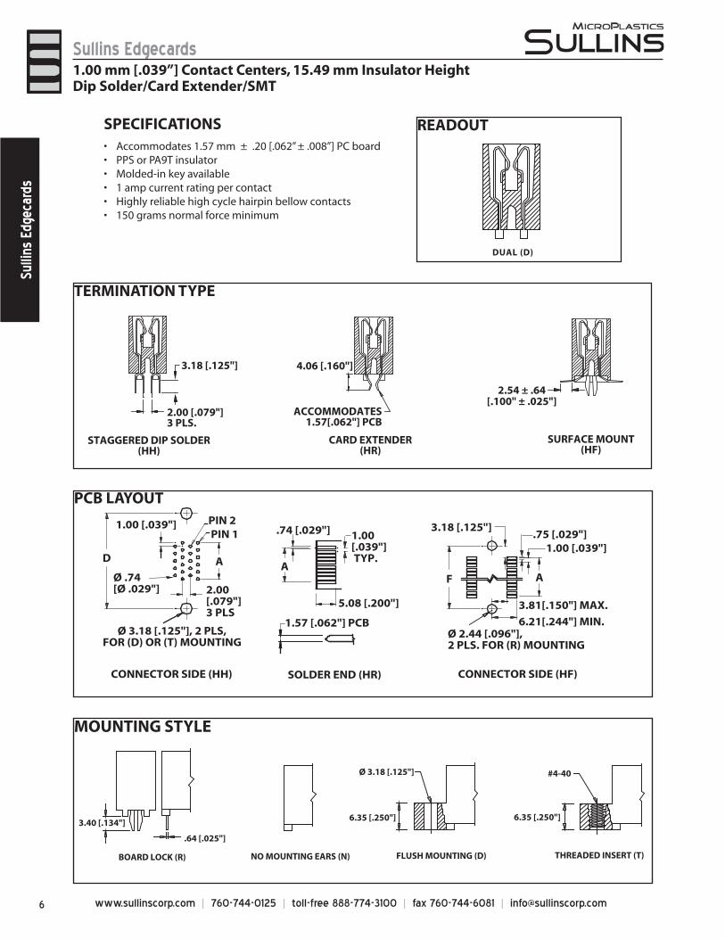
TERMINATION TYPE
STAGGERED DIP SOLDER(HH)
SURFACE MOUNT(HF)
CARD EXTENDER(HR)
3.18 [.125"] 4.06 [.160"]
ACCOMMODATES1.57[.062"] PCB
2.00 [.079"]3 PLS.
2.54 ± .64[.100" ± .025"]
PCB LAYOUT
CONNECTOR SIDE (HH) CONNECTOR SIDE (HF)SOLDER END (HR)
PIN 2PIN 1
1.00 [.039"]
Ø .74[Ø .029"]
Ø 3.18 [.125"], 2 PLS,FOR (D) OR (T) MOUNTING
2.00[.079"]3 PLS
1.00 [.039"] TYP.
.74 [.029"]
1.57 [.062"] PCB
5.08 [.200"]
.75 [.029"]3.18 [.125"]
1.00 [.039"]
Ø 2.44 [.096"],2 PLS. FOR (R) MOUNTING
6.21[.244"] MIN.
3.81[.150"] MAX.
AFAAD
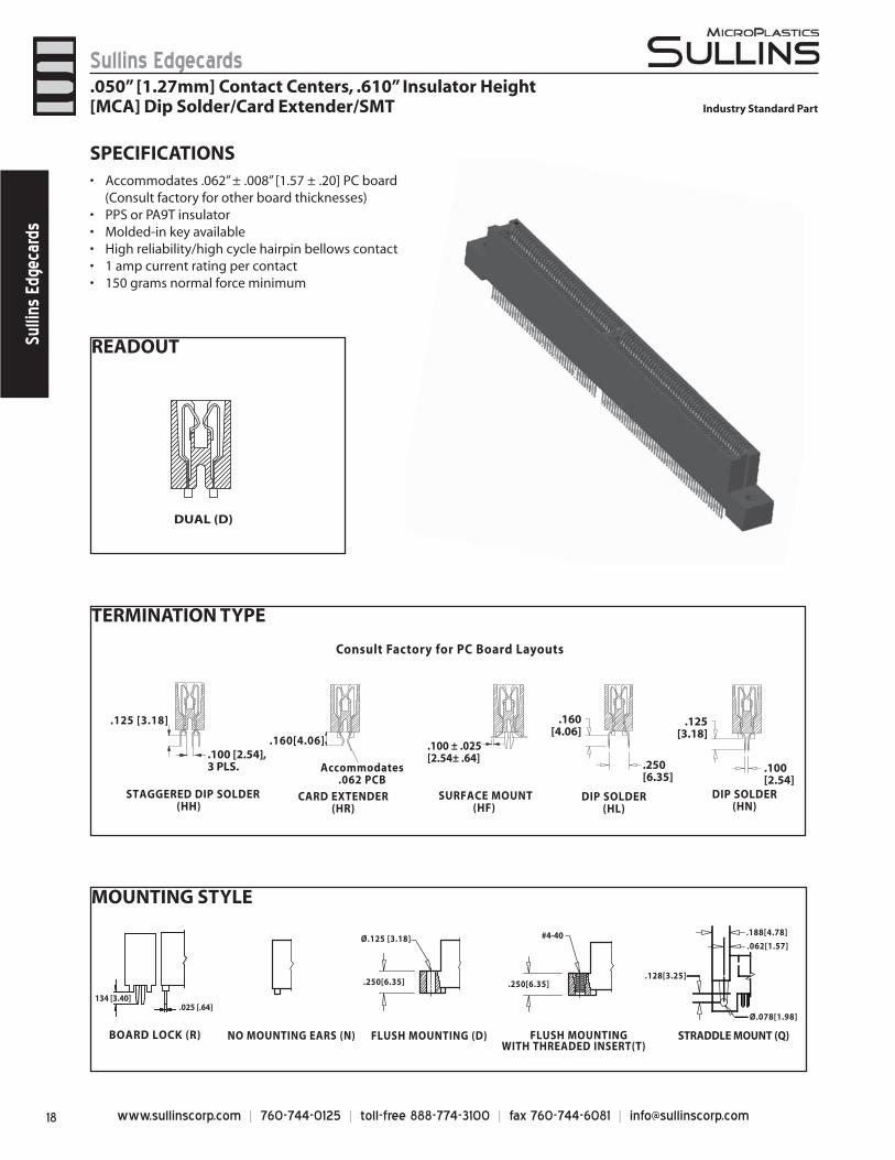
READOUT
DUAL (D)
SPECIFICATIONSAccommodates 1.57 mm ± .20 [.062” ± .008”] PC board• PPS or PA9T insulator• Molded-in key available• 1 amp current rating per contact• Highly reliable high cycle hairpin bellow contacts• 150 grams normal force minimum•
MOUNTING STYLE
THREADED INSERT (T)FLUSH MOUNTING (D)NO MOUNTING EARS (N)BOARD LOCK (R)
3.40 [.134"]
.64 [.025"]
Ø 3.18 [.125"]
6.35 [.250"] 6.35 [.250"]
#4-40
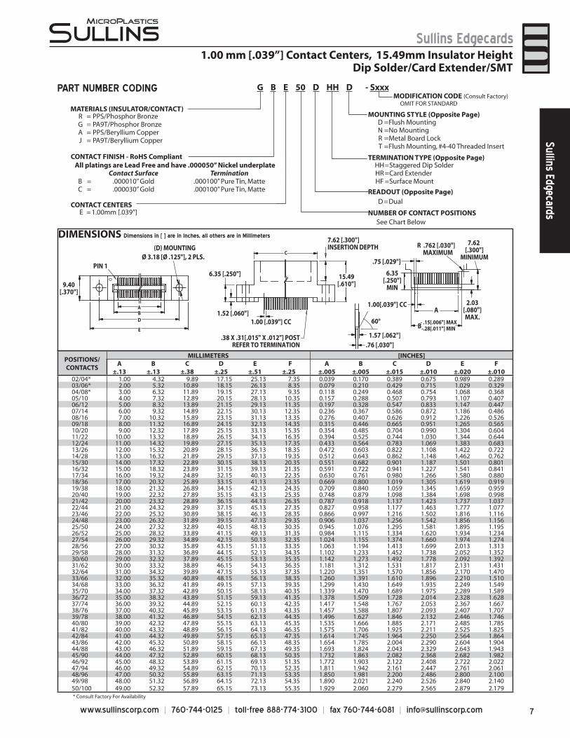
1.00 mm [.039”] Contact Centers, 15.49 mm Insulator Height Dip Solder/Card Extender/SMT
7www.sullinscorp.com | 760-744-0125 | toll-free 888-774-3100 | fax 760-744-6081 | [email protected]
Sullins EdgecardsSullins Edgecards
- .15[.006"] MAX -.28[.011"] MIN
Ø 3.18 [Ø .125"], 2 PLS.(D) MOUNTING
9.40[.370"]
6.35 [.250"]
1.52 [.060"]1.00 [.039"] CC
7.62 [.300"]INSERTION DEPTH
15.49 [.610"]
60°
1.57 [.062"].76 [.030"]
1.00[.039"] CC
.75 [.029"]
6.35[.250"]
MIN
R .762 [.030"]MAXIMUM
7.62 [.300"]
MINIMUM
2.03[.080"]MAX.
ABD
EB
A
C
PIN 1
.38 X .31[.015" X .012"] POSTREFER TO TERMINATION
POSITIONS/CONTACTS
MILLIMETERS [INCHES]A
±.13B
±.13C
±.38D
±.25E
±.51 F
±.25A
±.005B
±.005C
±.015D
±.010E
±.020F
±.01002/04* 1.00 4.32 9.89 17.15 25.13 7.35 0.039 0.170 0.389 0.675 0.989 0.28903/06* 2.00 5.32 10.89 18.15 26.13 8.35 0.079 0.210 0.429 0.715 1.029 0.32904/08* 3.00 6.32 11.89 19.15 27.13 9.35 0.118 0.249 0.468 0.754 1.068 0.36805/10 4.00 7.32 12.89 20.15 28.13 10.35 0.157 0.288 0.507 0.793 1.107 0.40706/12 5.00 8.32 13.89 21.15 29.13 11.35 0.197 0.328 0.547 0.833 1.147 0.44707/14 6.00 9.32 14.89 22.15 30.13 12.35 0.236 0.367 0.586 0.872 1.186 0.48608/16 7.00 10.32 15.89 23.15 31.13 13.35 0.276 0.407 0.626 0.912 1.226 0.52609/18 8.00 11.32 16.89 24.15 32.13 14.35 0.315 0.446 0.665 0.951 1.265 0.56510/20 9.00 12.32 17.89 25.15 33.13 15.35 0.354 0.485 0.704 0.990 1.304 0.60411/22 10.00 13.32 18.89 26.15 34.13 16.35 0.394 0.525 0.744 1.030 1.344 0.64412/24 11.00 14.32 19.89 27.15 35.13 17.35 0.433 0.564 0.783 1.069 1.383 0.68313/26 12.00 15.32 20.89 28.15 36.13 18.35 0.472 0.603 0.822 1.108 1.422 0.72214/28 13.00 16.32 21.89 29.15 37.13 19.35 0.512 0.643 0.862 1.148 1.462 0.76215/30 14.00 17.32 22.89 30.15 38.13 20.35 0.551 0.682 0.901 1.187 1.501 0.80116/32 15.00 18.32 23.89 31.15 39.13 21.35 0.591 0.722 0.941 1.227 1.541 0.84117/34 16.00 19.32 24.89 32.15 40.13 22.35 0.630 0.761 0.980 1.266 1.580 0.88018/36 17.00 20.32 25.89 33.15 41.13 23.35 0.669 0.800 1.019 1.305 1.619 0.91919/38 18.00 21.32 26.89 34.15 42.13 24.35 0.709 0.840 1.059 1.345 1.659 0.95920/40 19.00 22.32 27.89 35.15 43.13 25.35 0.748 0.879 1.098 1.384 1.698 0.99821/42 20.00 23.32 28.89 36.15 44.13 26.35 0.787 0.918 1.137 1.423 1.737 1.03722/44 21.00 24.32 29.89 37.15 45.13 27.35 0.827 0.958 1.177 1.463 1.777 1.07723/46 22.00 25.32 30.89 38.15 46.13 28.35 0.866 0.997 1.216 1.502 1.816 1.11624/48 23.00 26.32 31.89 39.15 47.13 29.35 0.906 1.037 1.256 1.542 1.856 1.15625/50 24.00 27.32 32.89 40.15 48.13 30.35 0.945 1.076 1.295 1.581 1.895 1.19526/52 25.00 28.32 33.89 41.15 49.13 31.35 0.984 1.115 1.334 1.620 1.934 1.23427/54 26.00 29.32 34.89 42.15 50.13 32.35 1.024 1.155 1.374 1.660 1.974 1.27428/56 27.00 30.32 35.89 43.15 51.13 33.35 1.063 1.194 1.413 1.699 2.013 1.31329/58 28.00 31.32 36.89 44.15 52.13 34.35 1.102 1.233 1.452 1.738 2.052 1.35230/60 29.00 32.32 37.89 45.15 53.13 35.35 1.142 1.273 1.492 1.778 2.092 1.39231/62 30.00 33.32 38.89 46.15 54.13 36.35 1.181 1.312 1.531 1.817 2.131 1.43132/64 31.00 34.32 39.89 47.15 55.13 37.35 1.220 1.351 1.570 1.856 2.170 1.47033/66 32.00 35.32 40.89 48.15 56.13 38.35 1.260 1.391 1.610 1.896 2.210 1.51034/68 33.00 36.32 41.89 49.15 57.13 39.35 1.299 1.430 1.649 1.935 2.249 1.54935/70 34.00 37.32 42.89 50.15 58.13 40.35 1.339 1.470 1.689 1.975 2.289 1.58936/72 35.00 38.32 43.89 51.15 59.13 41.35 1.378 1.509 1.728 2.014 2.328 1.62837/74 36.00 39.32 44.89 52.15 60.13 42.35 1.417 1.548 1.767 2.053 2.367 1.66738/76 37.00 40.32 45.89 53.15 61.13 43.35 1.457 1.588 1.807 2.093 2.407 1.70739/78 38.00 41.32 46.89 54.15 62.13 44.35 1.496 1.627 1.846 2.132 2.446 1.74640/80 39.00 42.32 47.89 55.15 63.13 45.35 1.535 1.666 1.885 2.171 2.485 1.78541/82 40.00 43.32 48.89 56.15 64.13 46.35 1.575 1.706 1.925 2.211 2.525 1.82542/84 41.00 44.32 49.89 57.15 65.13 47.35 1.614 1.745 1.964 2.250 2.564 1.86443/86 42.00 45.32 50.89 58.15 66.13 48.35 1.654 1.785 2.004 2.290 2.604 1.90444/88 43.00 46.32 51.89 59.15 67.13 49.35 1.693 1.824 2.043 2.329 2.643 1.94345/90 44.00 47.32 52.89 60.15 68.13 50.35 1.732 1.863 2.082 2.368 2.682 1.98246/92 45.00 48.32 53.89 61.15 69.13 51.35 1.772 1.903 2.122 2.408 2.722 2.02247/94 46.00 49.32 54.89 62.15 70.13 52.35 1.811 1.942 2.161 2.447 2.761 2.06148/96 47.00 50.32 55.89 63.15 71.13 53.35 1.850 1.981 2.200 2.486 2.800 2.10049/98 48.00 51.32 56.89 64.15 72.13 54.35 1.890 2.021 2.240 2.526 2.840 2.14050/100 49.00 52.32 57.89 65.15 73.13 55.35 1.929 2.060 2.279 2.565 2.879 2.179
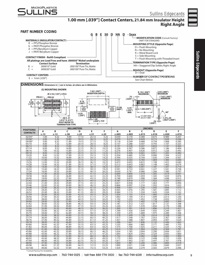
DIMENSIONS Dimensions in [ ] are in Inches, all others are in Millimeters
* Consult Factory For Availability
MATERIALS (INSULATOR/CONTACT)R = PPS/Phosphor BronzeG = PA9T/Phosphor BronzeA = PPS/Beryllium CopperJ = PA9T/Beryllium Copper
CONTACT FINISH - RoHS Compliant
CONTACT CENTERSE = 1.00mm [.039”] NUMBER OF CONTACT POSITIONS
See Chart Below
D =Dual
D =Flush MountingN =No MountingR =Metal Board LockT =Flush Mounting, #4-40 Threaded Insert
HH=Staggered Dip SolderHR =Card ExtenderHF =Surface Mount
PART NUMBER CODINGMODIFICATION CODE (Consult Factory) OMIT FOR STANDARD
READOUT (Opposite Page)
MOUNTING STYLE (Opposite Page)
TERMINATION TYPE (Opposite Page)
G B E 50 D HH D - Sxxx
1.00 mm [.039”] Contact Centers, 15.49mm Insulator Height Dip Solder/Card Extender/SMT
All platings are Lead Free and have .000050” Nickel underplateContact Surface Termination
B = .000010” Gold .000100” Pure Tin, MatteC = .000030” Gold .000100” Pure Tin, Matte
www.sullinscorp.com | 760-744-0125 | toll-free 888-774-3100 | fax 760-744-6081 | [email protected]
Sullins EdgecardsSu
llins
Edg
ecar
ds
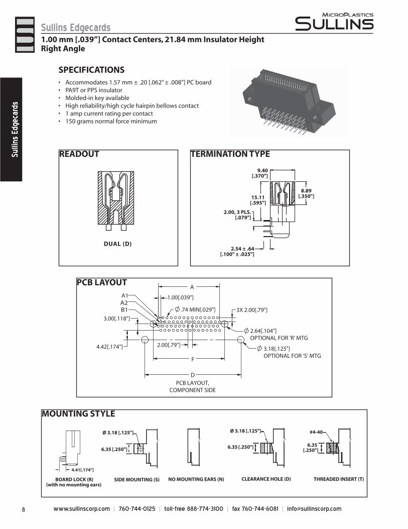
MOUNTING STYLE
THREADED INSERT (T)CLEARANCE HOLE (D)NO MOUNTING EARS (N)
#4-40 Ø 3.18 [.125"]
6.35 [.250"]
[.250"]6.35
SIDE MOUNTING (S)
[.250"]6.35
Ø 3.18 [.125"]
BOARD LOCK (R)(with no mounting ears)
4.41[.174"]
SPECIFICATIONSAccommodates 1.57 mm ± .20 [.062” ± .008”] PC board• PA9T or PPS insulator• Molded-in key available• High reliability/high cycle hairpin bellows contact• 1 amp current rating per contact• 150 grams normal force minimum•
READOUT
DUAL (D)
TERMINATION TYPE
9.40[.370"]
8.89[.350"]15.11
[.595"]
2.00, 3 PLS.[.079"]
2.54 ± .64[.100" ± .025"]
1.00 mm [.039”] Contact Centers, 21.84 mm Insulator Height Right Angle
PCB LAYOUT
2.64[.104"]OPTIONAL FOR 'R' MTG
F
.74 MIN[.029"]
1.00[.039"]
2.00[.79"]
3X 2.00[.79"]
4.42[.174"] 3.18[.125"]OPTIONAL FOR 'S' MTG
D
A
A1
B1
PCB LAYOUT,COMPONENT SIDE
3.00[.118"]
A2
9www.sullinscorp.com | 760-744-0125 | toll-free 888-774-3100 | fax 760-744-6081 | [email protected]
Sullins EdgecardsSullins Edgecards
DIMENSIONS Dimensions in [ ] are in Inches, all others are in Millimeters
1.00 mm [.039”] Contact Centers, 21.84 mm Insulator HeightRight Angle
PART NUMBER CODING
* Consult Factory For Availability
-.15 [.006"] MAX-.28 [.011"] MIN
F
(S) MOUNTING SHOWN
Ø 3.18 [.125"], 4 PLS
PIN A1 PIN A2
B1
9.40[.370"]
.38 X .31[.015" X .012"]
POST REFER TOTERMINATION TYPE
6.35[.250"]
MIN
1.00[.039"]
.75 [.029"]
R .76 [. 030"] MAXIMUM
2.03 [.080"] MAXIMUM
7.62 [.300"] MINIMUM
A
B
60°
1.57±.20 [.062"±.008"]
.76[.030"]
6.35 [.250"]
1.00[.039"], TYP
7.62 [.300"] INSERTION DEPTH
C
9.14[.360"]
ABDE
21.84[.860"]
MATERIALS (INSULATOR/CONTACT)R = PPS/Phosphor BronzeG = PA9T/Phosphor BronzeA = PPS/Beryllium CopperJ = PA9T/Beryllium Copper
CONTACT CENTERSE = 1mm [.039”]
NUMBER OF CONTACT POSITIONS
READOUT (Opposite Page)D = Dual
MOUNTING STYLE (Opposite Page)D = Flush MountingN = No MountingR = Metal Board LockS = Side MountingT = Flush Mounting with Threaded Insert
TERMINATION TYPE (Opposite Page)HA = Staggered Dip Solder, Right Angle
MODIFICATION CODE (Consult Factory) OMIT FOR STANDARD
See Chart Below
G B E 50 D HA D - Sxxx
POSITIONS/CONTACTS
MILLIMETERS [INCHES]A
±.13B
±.13C
±.38D
±.25E
±.51 F
±.25A
±.005B
±.005C
±.015D
±.010E
±.020F
±.01002/04* 1.00 4.32 9.89 17.15 25.13 5.25 0.039 0.170 0.389 0.675 0.989 0.20703/06* 2.00 5.32 10.89 18.15 26.13 6.25 0.079 0.210 0.429 0.715 1.029 0.24604/08* 3.00 6.32 11.89 19.15 27.13 7.25 0.118 0.249 0.468 0.754 1.068 0.28505/10 4.00 7.32 12.89 20.15 28.13 8.25 0.157 0.288 0.507 0.793 1.107 0.32506/12 5.00 8.32 13.89 21.15 29.13 9.25 0.197 0.328 0.547 0.833 1.147 0.36407/14 6.00 9.32 14.89 22.15 30.13 10.25 0.236 0.367 0.586 0.872 1.186 0.40408/16 7.00 10.32 15.89 23.15 31.13 11.25 0.276 0.407 0.626 0.912 1.226 0.44309/18 8.00 11.32 16.89 24.15 32.13 12.25 0.315 0.446 0.665 0.951 1.265 0.48210/20 9.00 12.32 17.89 25.15 33.13 13.25 0.354 0.485 0.704 0.990 1.304 0.52211/22 10.00 13.32 18.89 26.15 34.13 14.25 0.394 0.525 0.744 1.030 1.344 0.56112/24 11.00 14.32 19.89 27.15 35.13 15.25 0.433 0.564 0.783 1.069 1.383 0.60013/26 12.00 15.32 20.89 28.15 36.13 16.25 0.472 0.603 0.822 1.108 1.422 0.64014/28 13.00 16.32 21.89 29.15 37.13 17.25 0.512 0.643 0.862 1.148 1.462 0.67915/30 14.00 17.32 22.89 30.15 38.13 18.25 0.551 0.682 0.901 1.187 1.501 0.71916/32 15.00 18.32 23.89 31.15 39.13 19.25 0.591 0.722 0.941 1.227 1.541 0.75817/34 16.00 19.32 24.89 32.15 40.13 20.25 0.630 0.761 0.980 1.266 1.580 0.79718/36 17.00 20.32 25.89 33.15 41.13 21.25 0.669 0.800 1.019 1.305 1.619 0.93719/38 18.00 21.32 26.89 34.15 42.13 22.25 0.709 0.840 1.059 1.345 1.659 0.87620/40 19.00 22.32 27.89 35.15 43.13 23.25 0.748 0.879 1.098 1.384 1.698 0.91521/42 20.00 23.32 28.89 36.15 44.13 24.25 0.787 0.918 1.137 1.423 1.737 0.95522/44 21.00 24.32 29.89 37.15 45.13 25.25 0.827 0.958 1.177 1.463 1.777 0.99423/46 22.00 25.32 30.89 38.15 46.13 26.25 0.866 0.997 1.216 1.502 1.816 1.03324/48 23.00 26.32 31.89 39.15 47.13 27.25 0.906 1.037 1.256 1.542 1.856 1.07325/50 24.00 27.32 32.89 40.15 48.13 28.25 0.945 1.076 1.295 1.581 1.895 1.11226/52 25.00 28.32 33.89 41.15 49.13 29.25 0.984 1.115 1.334 1.620 1.934 1.15227/54 26.00 29.32 34.89 42.15 50.13 30.25 1.024 1.155 1.374 1.660 1.974 1.19128/56 27.00 30.32 35.89 43.15 51.13 31.25 1.063 1.194 1.413 1.699 2.013 1.23029/58 28.00 31.32 36.89 44.15 52.13 32.25 1.102 1.233 1.452 1.738 2.052 1.27030/60 29.00 32.32 37.89 45.15 53.13 33.25 1.142 1.273 1.492 1.778 2.092 1.30931/62 30.00 33.32 38.89 46.15 54.13 34.25 1.181 1.312 1.531 1.817 2.131 1.34832/64 31.00 34.32 39.89 47.15 55.13 35.25 1.220 1.351 1.570 1.856 2.170 1.38833/66 32.00 35.32 40.89 48.15 56.13 36.25 1.260 1.391 1.610 1.896 2.210 1.42734/68 33.00 36.32 41.89 49.15 57.13 37.25 1.299 1.430 1.649 1.935 2.249 1.46735/70 34.00 37.32 42.89 50.15 58.13 38.25 1.339 1.470 1.689 1.975 2.289 1.50636/72 35.00 38.32 43.89 51.15 59.13 39.25 1.378 1.509 1.728 2.014 2.328 1.54537/74 36.00 39.32 44.89 52.15 60.13 40.25 1.417 1.548 1.767 2.053 2.367 1.58538/76 37.00 40.32 45.89 53.15 61.13 41.25 1.457 1.588 1.807 2.093 2.407 1.62439/78 38.00 41.32 46.89 54.15 62.13 42.25 1.496 1.627 1.846 2.132 2.446 1.66340/80 39.00 42.32 47.89 55.15 63.13 43.25 1.535 1.666 1.885 2.171 2.485 1.70341/82 40.00 43.32 48.89 56.15 64.13 44.25 1.575 1.706 1.925 2.211 2.525 1.74242/84 41.00 44.32 49.89 57.15 65.13 45.25 1.614 1.745 1.964 2.250 2.564 1.78143/86 42.00 45.32 50.89 58.15 66.13 46.25 1.654 1.785 2.004 2.290 2.604 1.82144/88 43.00 46.32 51.89 59.15 67.13 47.25 1.693 1.824 2.043 2.329 2.643 1.86045/90 44.00 47.32 52.89 60.15 68.13 48.25 1.732 1.863 2.082 2.368 2.682 1.90046/92 45.00 48.32 53.89 61.15 69.13 49.25 1.772 1.903 2.122 2.408 2.722 1.93947/94 46.00 49.32 54.89 62.15 70.13 50.25 1.811 1.942 2.161 2.447 2.761 1.97848/96 47.00 50.32 55.89 63.15 71.13 51.25 1.850 1.981 2.200 2.486 2.800 2.01849/98 48.00 51.32 56.89 64.15 72.13 52.25 1.890 2.021 2.240 2.526 2.840 2.05750/100 49.00 52.32 57.89 65.15 73.13 53.25 1.929 2.060 2.279 2.565 2.879 2.096
CONTACT FINISH - RoHS CompliantAll platings are Lead Free and have .000050” Nickel underplate
Contact Surface TerminationB = .000010” Gold .000100” Pure Tin, MatteC = .000030” Gold .000100” Pure Tin, Matte
www.sullinscorp.com | 760-744-0125 | toll-free 888-774-3100 | fax 760-744-6081 | [email protected]
Sullins EdgecardsSu
llins
Edg
ecar
ds
1.00 mm [.039”] Contact Centers, PCI Express, Dip Solder
POSITIONS/CONTACTS
MILLIMETERS [INCHES]
A ± 0.15 B ± 0.15 C ± 0.15 D ± 0.15 A ± 0.006” B ± 0.006” C ± 0.006” D ± 0.006”
18/36 6.00 7.65 25.00 9.15 0.236 0.301 0.984 0.360
32/64 20.00 21.65 39.00 23.15 0.787 0.852 1.535 0.911
49/98 37.00 38.65 56.00 40.15 1.457 1.522 2.205 1.581
82/164 70.00 71.65 89.00 73.15 2.756 2.821 3.504 2.880
PIN A1IDENTIFIER
14.50[.571"]
8.85[.348"]
A
1.50[.059"]
0.34x0.25 [.013"x.010"]REFER TO TERMINATION
1.00[.039"] TYP
1.35[.053"]1.65[.065"]
1.20[.047"]
15.60[.614"]
11.25[ .443"]MAX
11.65[.459"]
1.73±0.08[.068"±.003"]
B
D
7.50[.295"]
1.50[.059"] MAX
C
STAGGERED DIP SOLDER (HH)
10.00[.394"]
PIN A1
PIN B1
10.00[.394"]
37.00[1.457"]
1.00[.039"] TYP.
90.00[3.543"]
7.50[.295"] MAX
8.85[.348"]
149.00±0.25 [5.866"±.010"]131.68[5.184"]
91.68[3.609"]1.73±0.08[.068"±.003"] 1.50[.059"]
1.20[.047"]
133.15[5.242"]
0.34x0.25 [.013"x.010"]
11.67[.459"]
38.27[1.507"]1.73±0.08[.068"±.003"]
11.25[.442"]MAX
14.65[.577"]
40.00[1.575"]
140/280 POSITION, STAGGERED DIP SOLDER (HH)
1.00[.039"] REF. 0.34x0.25 [.013"x.010"]
11.25[.442"]MAX
1.20[.047"]
14.65[.577"]
106.15[4.179"]
1.73±0.08[.068"±.003"]
11.68[.460"]
122.00±0.25[4.803"±.010"]
104.67[4.121"]
1.00[.039"] TYP.1.50[.059"] REF.
10.00[.394"] REF.
103.00[4.055"] REF.
115/230 POSITION, STAGGERED DIP SOLDER (HH)
15.60[.614"]
15.60[.614"]
7.50[.295"] MAX
8.85[.348"]
PIN A1 IDENTIFIER
PIN A1
PIN B1
PIN A1
PIN B1
PIN A1 IDENTIFIER
DIMENSIONS Dimensions in [ ] are in Inches, all others are in Millimeters
11www.sullinscorp.com | 760-744-0125 | toll-free 888-774-3100 | fax 760-744-6081 | [email protected]
Sullins EdgecardsSullins Edgecards
1.00 mm [.039”] Contact Centers, PCI Express, Dip Solder
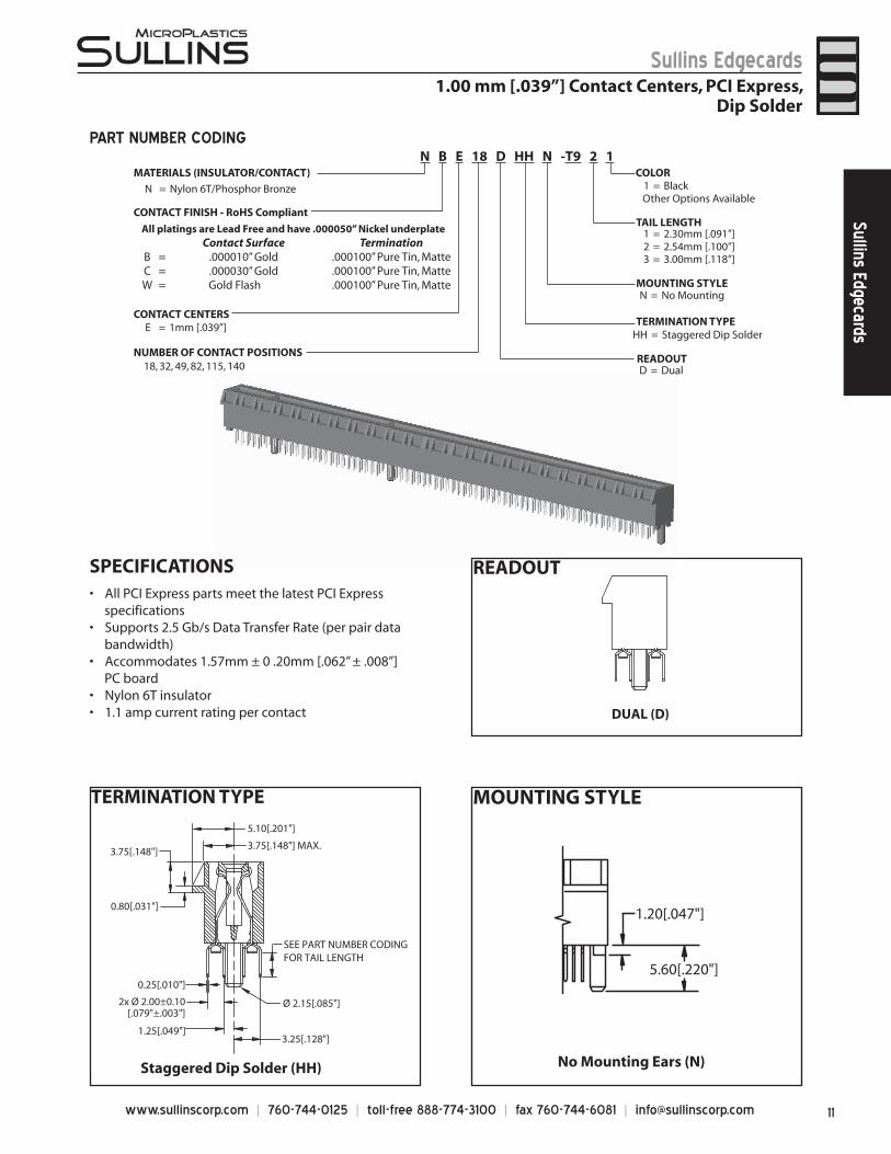
PART NUMBER CODING
MOUNTING STYLETERMINATION TYPE
3.25[.128"]1.25[.049"]
Ø 2.15[.085"]
SEE PART NUMBER CODING FOR TAIL LENGTH
2x Ø 2.00±0.10[.079"±.003"]
Staggered Dip Solder (HH)
5.10[.201"]
3.75[.148"] MAX.3.75[.148"]
0.80[.031"]
0.25[.010"]
MATERIALS (INSULATOR/CONTACT)
CONTACT CENTERSE = 1mm [.039”]
All platings are Lead Free and have .000050” Nickel underplate Contact Surface Termination
B = .000010” Gold .000100” Pure Tin, MatteC = .000030” Gold .000100” Pure Tin, MatteW = Gold Flash .000100” Pure Tin, Matte MOUNTING STYLE
TAIL LENGTH
READOUTD = Dual
N = No Mounting
TERMINATION TYPEHH = Staggered Dip Solder
1 = 2.30mm [.091”]2 = 2.54mm [.100”]3 = 3.00mm [.118”]
NUMBER OF CONTACT POSITIONS18, 32, 49, 82, 115, 140
COLOR
N = Nylon 6T/Phosphor Bronze 1 = Black Other Options Available
N B E 18 D HH N -T9 2 1
5.60[.220"]
1.20[.047"]
No Mounting Ears (N)
SPECIFICATIONSAll PCI Express p• arts meet the latest PCI Express
specificationsSupports 2.5 Gb/s Data Transfer Rate (per pair data •
bandwidth)Accommodates 1.57mm ± 0 .20mm [.062” ± .008”] •
PC boardNylon 6T insulator• 1.1 amp current rating• per contact
READOUT
DUAL (D)
CONTACT FINISH - RoHS Compliant
www.sullinscorp.com | 760-744-0125 | toll-free 888-774-3100 | fax 760-744-6081 | [email protected]
Sullins EdgecardsSu
llins
Edg
ecar
ds
DIMENSIONS Dimensions in [ ] are in Inches, all others are in Millimeters
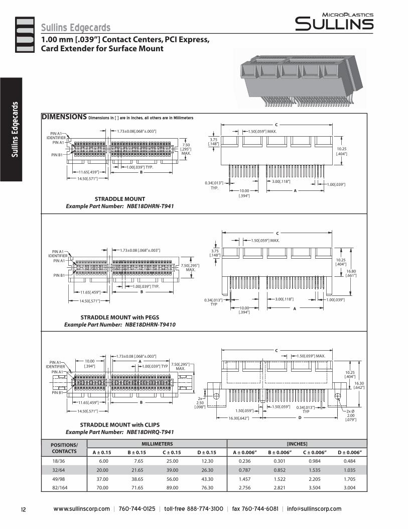
1.00 mm [.039”] Contact Centers, PCI Express, Card Extender for Surface Mount
0.34[.013"] TYP
16.30[.642"]
1.50[.059"]1.50[.059"]
1.50[.059"] MAX.
2x Ø 2.00
[.079"]
2x2.50
[.098"]
10.25[.404"]
7.50[.295"]MAX.
1.00[.039"] TYP
14.50[.571"]
11.65[.459"]
1.73±0.08 [.068"±.003"]10.00[.394"]
PIN A1
C
B
A
D
PIN A1
1.00[.039"] TYP.
1.73±0.08[.068"±.003"]
7.50[.295"] MAX.
11.65[.459"]
14.50[.571"]
C
3.75[.148"]
1.50[.059"] MAX.
10.25[.404"]
1.00[.039"]0.34[.013"] TYP.
10.00[.394"]
3.00[.118"]
B
A
10.25[.404"]
PIN A1
C
A
B
STRADDLE MOUNTExample Part Number: NBE18DHRN-T941
STRADDLE MOUNT with PEGSExample Part Number: NBE18DHRN-T9410
STRADDLE MOUNT with CLIPSExample Part Number: NBE18DHRQ-T941
PIN A1IDENTIFIER
PIN B1
PIN A1IDENTIFIER
PIN B1
PIN A1IDENTIFIER
PIN B1
1.00[.039"] TYP.
7.50[.295"] MAX.
3.75[.148"]
14.50[.571"]
11.65[.459"]
1.73±0.08 [.068"±.003"]
1.50[.059"] MAX.
0.34[.013"] TYP
10.00[.394"]
3.00[.118"] 1.00[.039"]
16.80[.661"]
16.30[.642"]
POSITIONS/CONTACTS
MILLIMETERS [INCHES]
A ± 0.15 B ± 0.15 C ± 0.15 D ± 0.15 A ± 0.006” B ± 0.006” C ± 0.006” D ± 0.006”
18/36 6.00 7.65 25.00 12.30 0.236 0.301 0.984 0.484
32/64 20.00 21.65 39.00 26.30 0.787 0.852 1.535 1.035
49/98 37.00 38.65 56.00 43.30 1.457 1.522 2.205 1.705
82/164 70.00 71.65 89.00 76.30 2.756 2.821 3.504 3.004
13www.sullinscorp.com | 760-744-0125 | toll-free 888-774-3100 | fax 760-744-6081 | [email protected]
Sullins EdgecardsSullins Edgecards
1.00 mm [.039”] Contact Centers, PCI Express, Card Extender for Surface Mount
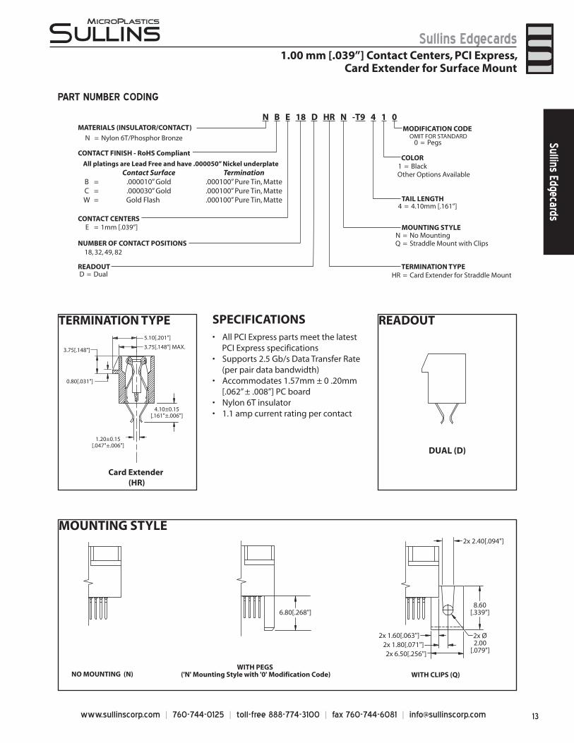
PART NUMBER CODING
MATERIALS (INSULATOR/CONTACT)
CONTACT CENTERSE = 1mm [.039”]
All platings are Lead Free and have .000050” Nickel underplate Contact Surface Termination
B = .000010” Gold .000100” Pure Tin, MatteC = .000030” Gold .000100” Pure Tin, MatteW = Gold Flash .000100” Pure Tin, Matte
READOUTD = Dual
MOUNTING STYLEN = No MountingQ = Straddle Mount with Clips
TERMINATION TYPEHR = Card Extender for Straddle Mount
TAIL LENGTH4 = 4.10mm [.161”]
NUMBER OF CONTACT POSITIONS18, 32, 49, 82
N = Nylon 6T/Phosphor Bronze
COLOR1 = Black
Other Options Available
N B E 18 D HR N -T9 4 1 0MODIFICATION CODE OMIT FOR STANDARD
0 = Pegs
MOUNTING STYLE
2x 1.60[.063"]
2x 6.50[.256"]2x 1.80[.071"]
2x Ø2.00
[.079"]
2x 2.40[.094"]
NO MOUNTING (N)WITH PEGS
('N' Mounting Style with '0' Modification Code) WITH CLIPS (Q)
8.60[.339"]6.80[.268"]
SPECIFICATIONSAll PCI Express p• arts meet the latest
PCI Express specificationsSupports 2.5 Gb/s Data Transfer Rate•
(per pair data bandwidth)Accommodates 1.57mm ± 0 .20mm•
[.062” ± .008”] PC boardNylon 6T insulator• 1.1 amp current rating• per contact
TERMINATION TYPE
Card Extender (HR)
1.20±0.15[.047"±.006"]
4.10±0.15[.161"±.006"]
5.10[.201"]
3.75[.148"] MAX.3.75[.148"]
0.80[.031"]
READOUT
DUAL (D)
CONTACT FINISH - RoHS Compliant
www.sullinscorp.com | 760-744-0125 | toll-free 888-774-3100 | fax 760-744-6081 | [email protected]
Sullins EdgecardsSu
llins
Edg
ecar
ds
MOUNTING STYLE
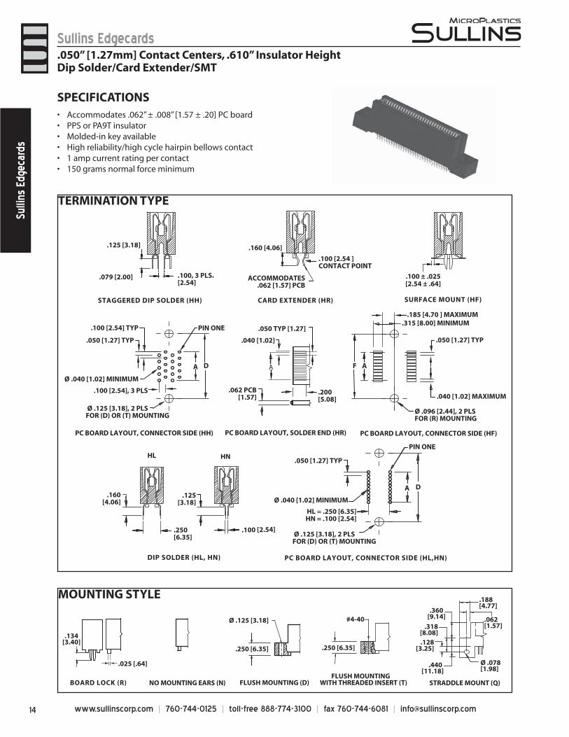
TERMINATION TYPE
FLUSH MOUNTINGWITH THREADED INSERT (T)FLUSH MOUNTING (D)NO MOUNTING EARS (N)
#4-40 Ø .125 [3.18]
.250 [6.35].250 [6.35]
STRADDLE MOUNT (Q)BOARD LOCK (R)
.134[3.40]
.025 [.64]
.188 [4.77]
.062[1.57]
.360[9.14]
.318[8.08]
Ø .078[1.98]
.128[3.25]
.440 [11.18]
SPECIFICATIONSAccommodates .062” ± .008” [1.57 ± .20] PC board• PPS or PA9T insulator• Molded-in key available• High reliability/high cycle hairpin bellows contact• 1 amp current rating per contact• 150 grams normal force minimum•
AA
Ø .096 [2.44], 2 PLSFOR (R) MOUNTING
Ø .040 [1.02] MINIMUM
.185 [4.70 ] MAXIMUM .315 [8.00] MINIMUM
F
.050 [1.27] TYP
.040 [1.02] MAXIMUM
PC BOARD LAYOUT, CONNECTOR SIDE (HH)
.200[5.08]
.100 [2.54] TYP
D
.100 [2.54], 3 PLS
.050 [1.27] TYP
PIN ONE
.040 [1.02]
.062 PCB[1.57]
.050 TYP [1.27]
A
STAGGERED DIP SOLDER (HH) CARD EXTENDER (HR) SURFACE MOUNT (HF)
.100, 3 PLS.[2.54]
PC BOARD LAYOUT, SOLDER END (HR) PC BOARD LAYOUT, CONNECTOR SIDE (HF)
Ø .125 [3.18], 2 PLSFOR (D) OR (T) MOUNTING
Ø .040 [1.02] MINIMUM
PC BOARD LAYOUT, CONNECTOR SIDE (HL,HN)
D
HL = .250 [6.35]HN = .100 [2.54]
.050 [1.27] TYP
PIN ONE
A
DIP SOLDER (HL, HN)
.160[4.06]
.250[6.35]
.125[3.18]
.100 [2.54]
HL HN
Ø .125 [3.18], 2 PLSFOR (D) OR (T) MOUNTING
.079 [2.00]
.125 [3.18] .160 [4.06]
ACCOMMODATES .062 [1.57] PCB
.100 [2.54 ] CONTACT POINT
.100 ± .025[2.54 ± .64]
.050” [1.27mm] Contact Centers, .610” Insulator HeightDip Solder/Card Extender/SMT
15www.sullinscorp.com | 760-744-0125 | toll-free 888-774-3100 | fax 760-744-6081 | [email protected]
Sullins EdgecardsSullins Edgecards
.050” [1.27mm] Contact Centers, .610” Insulator HeightDip Solder/Card Extender/SMT
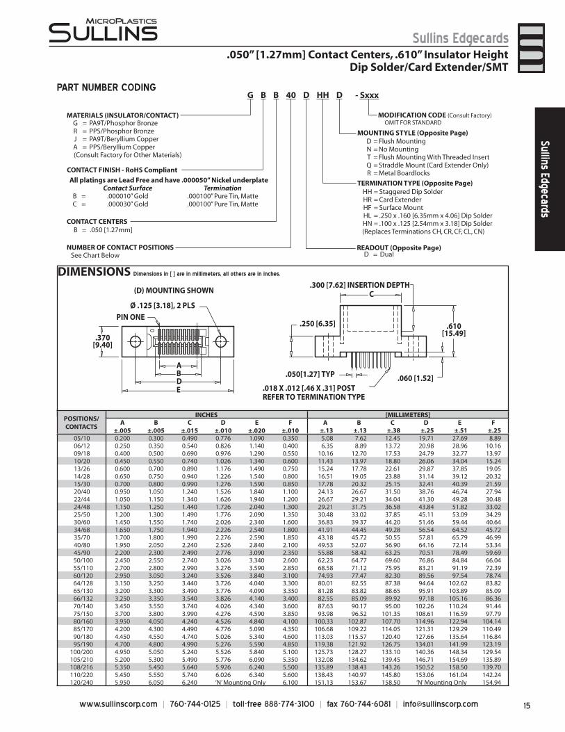
MATERIALS (INSULATOR/CONTACT)G = PA9T/Phosphor BronzeR = PPS/Phosphor BronzeJ = PA9T/Beryllium CopperA = PPS/Beryllium Copper
(Consult Factory for Other Materials)
CONTACT CENTERSB = .050 [1.27mm]
NUMBER OF CONTACT POSITIONS READOUT (Opposite Page)D = Dual
MOUNTING STYLE (Opposite Page)D = Flush MountingN = No MountingT = Flush Mounting With Threaded InsertQ = Straddle Mount (Card Extender Only)R = Metal Boardlocks
TERMINATION TYPE (Opposite Page)HH = Staggered Dip SolderHR = Card ExtenderHF = Surface MountHL = .250 x .160 [6.35mm x 4.06] Dip SolderHN = .100 x .125 [2.54mm x 3.18] Dip Solder(Replaces Terminations CH, CR, CF, CL, CN)
MODIFICATION CODE (Consult Factory) OMIT FOR STANDARD
All platings are Lead Free and have .000050” Nickel underplateContact Surface Termination
B = .000010” Gold .000100” Pure Tin, MatteC = .000030” Gold .000100” Pure Tin, Matte
See Chart Below
PART NUMBER CODING
PIN ONE
.050[1.27] TYP
.370[9.40]
Ø .125 [3.18], 2 PLS
(D) MOUNTING SHOWN
AB
.018 X .012 [.46 X .31] POSTREFER TO TERMINATION TYPE
ED
.250 [6.35]
.060 [1.52]
.610[15.49]
.300 [7.62] INSERTION DEPTH C
DIMENSIONS Dimensions in [ ] are in millimeters, all others are in inches.
G B B 40 D HH D - Sxxx
POSITIONS/CONTACTS
INCHES [MILLIMETERS]A
±.005B
±.005C
±.015D
±.010E
±.020F
±.010 A B C D E F
±.13 ±.13 ±.38 ±.25 ±.51 ±.2505/10 0.200 0.300 0.490 0.776 1.090 0.350 5.08 7.62 12.45 19.71 27.69 8.8906/12 0.250 0.350 0.540 0.826 1.140 0.400 6.35 8.89 13.72 20.98 28.96 10.1609/18 0.400 0.500 0.690 0.976 1.290 0.550 10.16 12.70 17.53 24.79 32.77 13.9710/20 0.450 0.550 0.740 1.026 1.340 0.600 11.43 13.97 18.80 26.06 34.04 15.2413/26 0.600 0.700 0.890 1.176 1.490 0.750 15.24 17.78 22.61 29.87 37.85 19.0514/28 0.650 0.750 0.940 1.226 1.540 0.800 16.51 19.05 23.88 31.14 39.12 20.3215/30 0.700 0.800 0.990 1.276 1.590 0.850 17.78 20.32 25.15 32.41 40.39 21.5920/40 0.950 1.050 1.240 1.526 1.840 1.100 24.13 26.67 31.50 38.76 46.74 27.9422/44 1.050 1.150 1.340 1.626 1.940 1.200 26.67 29.21 34.04 41.30 49.28 30.4824/48 1.150 1.250 1.440 1.726 2.040 1.300 29.21 31.75 36.58 43.84 51.82 33.0225/50 1.200 1.300 1.490 1.776 2.090 1.350 30.48 33.02 37.85 45.11 53.09 34.2930/60 1.450 1.550 1.740 2.026 2.340 1.600 36.83 39.37 44.20 51.46 59.44 40.6434/68 1.650 1.750 1.940 2.226 2.540 1.800 41.91 44.45 49.28 56.54 64.52 45.7235/70 1.700 1.800 1.990 2.276 2.590 1.850 43.18 45.72 50.55 57.81 65.79 46.9940/80 1.950 2.050 2.240 2.526 2.840 2.100 49.53 52.07 56.90 64.16 72.14 53.3445/90 2.200 2.300 2.490 2.776 3.090 2.350 55.88 58.42 63.25 70.51 78.49 59.6950/100 2.450 2.550 2.740 3.026 3.340 2.600 62.23 64.77 69.60 76.86 84.84 66.0455/110 2.700 2.800 2.990 3.276 3.590 2.850 68.58 71.12 75.95 83.21 91.19 72.3960/120 2.950 3.050 3.240 3.526 3.840 3.100 74.93 77.47 82.30 89.56 97.54 78.7464/128 3.150 3.250 3.440 3.726 4.040 3.300 80.01 82.55 87.38 94.64 102.62 83.8265/130 3.200 3.300 3.490 3.776 4.090 3.350 81.28 83.82 88.65 95.91 103.89 85.0966/132 3.250 3.350 3.540 3.826 4.140 3.400 82.55 85.09 89.92 97.18 105.16 86.3670/140 3.450 3.550 3.740 4.026 4.340 3.600 87.63 90.17 95.00 102.26 110.24 91.4475/150 3.700 3.800 3.990 4.276 4.590 3.850 93.98 96.52 101.35 108.61 116.59 97.7980/160 3.950 4.050 4.240 4.526 4.840 4.100 100.33 102.87 107.70 114.96 122.94 104.1485/170 4.200 4.300 4.490 4.776 5.090 4.350 106.68 109.22 114.05 121.31 129.29 110.4990/180 4.450 4.550 4.740 5.026 5.340 4.600 113.03 115.57 120.40 127.66 135.64 116.8495/190 4.700 4.800 4.990 5.276 5.590 4.850 119.38 121.92 126.75 134.01 141.99 123.19
100/200 4.950 5.050 5.240 5.526 5.840 5.100 125.73 128.27 133.10 140.36 148.34 129.54105/210 5.200 5.300 5.490 5.776 6.090 5.350 132.08 134.62 139.45 146.71 154.69 135.89108/216 5.350 5.450 5.640 5.926 6.240 5.500 135.89 138.43 143.26 150.52 158.50 139.70110/220 5.450 5.550 5.740 6.026 6.340 5.600 138.43 140.97 145.80 153.06 161.04 142.24120/240 5.950 6.050 6.240 ‘N’ Mounting Only 6.100 151.13 153.67 158.50 ‘N’ Mounting Only 154.94
CONTACT FINISH - RoHS Compliant
www.sullinscorp.com | 760-744-0125 | toll-free 888-774-3100 | fax 760-744-6081 | [email protected]
Sullins EdgecardsSu
llins
Edg
ecar
ds
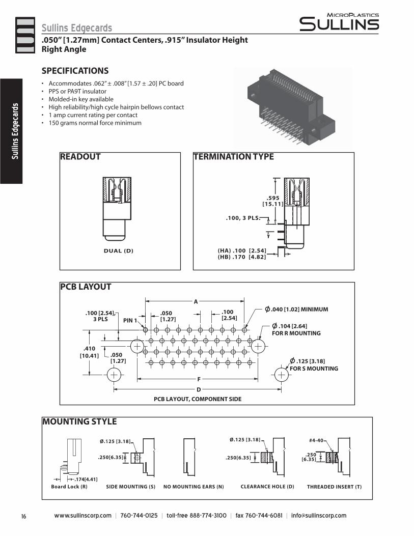
MOUNTING STYLE
THREADED INSERT (T)CLEARANCE HOLE (D)NO MOUNTING EARS (N)
#4-40 Ø.125 [3.18]
.250[6.35]
SIDE MOUNTING (S)
Ø.125 [3.18]
Board Lock (R)
.250[6.35].250[6.35]
.174[4.41]
TERMINATION TYPE
.595[15.11]
.100, 3 PLS.
(HA) .100 [2.54](HB) .170 [4.82]
READOUT
DUAL (D)
SPECIFICATIONSAccommodates .062” ± .008” [1.57 ± .20] PC board• PPS or PA9T insulator• Molded-in key available• High reliability/high cycle hairpin bellows contact• 1 amp current rating per contact• 150 grams normal force minimum•
PCB LAYOUT
A
D
F
PIN 1
FOR S MOUNTING.125 [3.18]
.040 [1.02] MINIMUM
.104 [2.64]FOR R MOUNTING
.100[2.54]
.050[1.27]
.100 [2.54],3 PLS
.050[1.27]
.410[10.41]
PCB LAYOUT, COMPONENT SIDE
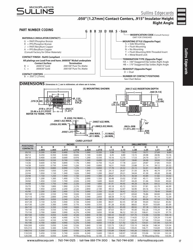
.050” [1.27mm] Contact Centers, .915” Insulator Height Right Angle
17www.sullinscorp.com | 760-744-0125 | toll-free 888-774-3100 | fax 760-744-6081 | [email protected]
Sullins EdgecardsSullins Edgecards
DIMENSIONS Dimensions in [ ] are in millimeters, all others are in inches.
MATERIALS (INSULATOR/CONTACT)G = PA9T/Phosphor BronzeR = PPS/Phosphor BronzeJ = PA9T/Beryllium CopperA = PPS/Beryllium Copper
(Consult Factory for Other Materials)
CONTACT CENTERSB = .050” [1.27mm] NUMBER OF CONTACT POSITIONS
D = Dual
S = Side MountingD = Flush MountingN = No MountingT = Flush Mounting With Threaded InsertR = Metal Board Lock
HA = .100” Staggered Dip Solder, Right AngleHB = .170” Staggered Dip Solder, Right Angle
READOUT (Opposite Page)
MOUNTING STYLE (Opposite Page)
TERMINATION TYPE (Opposite Page)
MODIFICATION CODE (Consult Factory) OMIT FOR STANDARD
All platings are Lead Free and have .000050” Nickel underplateContact Surface Termination
B = .000010” Gold .000100” Pure Tin, MatteC = .000030” Gold .000100” Pure Tin, Matte
See Chart Below
G B B 10 D HA S - Sxxx
.050” [1.27mm] Contact Centers, .915” Insulator HeightRight Angle
PART NUMBER CODING
A1
B1
A2
.915 [23.23]
D
Ø .125 [3.18], 4 PLS
B2
30°
.050[1.27]B
A
.040[1.02] MAX.R .030[.76] MAX.
.030[.76]
.062±.008[1.57±.20]
.300[7.62] MIN.
.080[2.03] MAX..250[6.35] MIN.
E
C
.250[6.35]
.610[15.49]
.050 CC[1.27]
.018 x .012 [0.46 x 0.31] POST
REFER TO TERM. TYPE
.360 [9.14]
A
B
CARD LAYOUT
(S) MOUNTING SHOWN .300 [7.62] INSERTION DEPTH
.370 [9.40]
-.006 MAX. -.011 MIN.
F
- .15 MAX.- .28 MIN.
CONTACT FINISH - RoHS Compliant
POSITIONS/CONTACTS
INCHES [MILLIMETERS]A
±.005B
±.005C
±.015D
±.010E
±.020F
±.010 A B C D E F
±.13 ±.13 ±.38 ±.25 ±.51 ±.2505/10 0.200 0.300 0.490 0.776 1.090 0.350 5.08 7.62 12.45 19.71 27.69 8.8906/12 0.250 0.350 0.540 0.826 1.140 0.400 6.35 8.89 13.72 20.98 28.96 10.1609/18 0.400 0.500 0.690 0.976 1.290 0.550 10.16 12.70 17.53 24.79 32.77 13.9710/20 0.450 0.550 0.740 1.026 1.340 0.600 11.43 13.97 18.80 26.06 34.04 15.2413/26 0.600 0.700 0.890 1.176 1.490 0.750 15.24 17.78 22.61 29.87 37.85 19.0514/28 0.650 0.750 0.940 1.226 1.540 0.800 16.51 19.05 23.88 31.14 39.12 20.3215/30 0.700 0.800 0.990 1.276 1.590 0.850 17.78 20.32 25.15 32.41 40.39 21.5920/40 0.950 1.050 1.240 1.526 1.840 1.100 24.13 26.67 31.50 38.76 46.74 27.9422/44 1.050 1.150 1.340 1.626 1.940 1.200 26.67 29.21 34.04 41.30 49.28 30.4824/48 1.150 1.250 1.440 1.726 2.040 1.300 29.21 31.75 36.58 43.84 51.82 33.0225/50 1.200 1.300 1.490 1.776 2.090 1.350 30.48 33.02 37.85 45.11 53.09 34.2930/60 1.450 1.550 1.740 2.026 2.340 1.600 36.83 39.37 44.20 51.46 59.44 40.6434/68 1.650 1.750 1.940 2.226 2.540 1.800 41.91 44.45 49.28 56.54 64.52 45.7235/70 1.700 1.800 1.990 2.276 2.590 1.850 43.18 45.72 50.55 57.81 65.79 46.9940/80 1.950 2.050 2.240 2.526 2.840 2.100 49.53 52.07 56.90 64.16 72.14 53.3445/90 2.200 2.300 2.490 2.776 3.090 2.350 55.88 58.42 63.25 70.51 78.49 59.6950/100 2.450 2.550 2.740 3.026 3.340 2.600 62.23 64.77 69.60 76.86 84.84 66.0455/110 2.700 2.800 2.990 3.276 3.590 2.850 68.58 71.12 75.95 83.21 91.19 72.3960/120 2.950 3.050 3.240 3.526 3.840 3.100 74.93 77.47 82.30 89.56 97.54 78.7464/128 3.150 3.250 3.440 3.726 4.040 3.300 80.01 82.55 87.38 94.64 102.62 83.8265/130 3.200 3.300 3.490 3.776 4.090 3.350 81.28 83.82 88.65 95.91 103.89 85.0966/132 3.250 3.350 3.540 3.826 4.140 3.400 82.55 85.09 89.92 97.18 105.16 86.3670/140 3.450 3.550 3.740 4.026 4.340 3.600 87.63 90.17 95.00 102.26 110.24 91.4475/150 3.700 3.800 3.990 4.276 4.590 3.850 93.98 96.52 101.35 108.61 116.59 97.7980/160 3.950 4.050 4.240 4.526 4.840 4.100 100.33 102.87 107.70 114.96 122.94 104.1485/170 4.200 4.300 4.490 4.776 5.090 4.350 106.68 109.22 114.05 121.31 129.29 110.4990/180 4.450 4.550 4.740 5.026 5.340 4.600 113.03 115.57 120.40 127.66 135.64 116.8495/190 4.700 4.800 4.990 5.276 5.590 4.850 119.38 121.92 126.75 134.01 141.99 123.19
100/200 4.950 5.050 5.240 5.526 5.840 5.100 125.73 128.27 133.10 140.36 148.34 129.54105/210 5.200 5.300 5.490 5.776 6.090 5.350 132.08 134.62 139.45 146.71 154.69 135.89108/216 5.350 5.450 5.640 5.926 6.240 5.500 135.89 138.43 143.26 150.52 158.50 139.70110/220 5.450 5.550 5.740 6.026 6.340 5.600 138.43 140.97 145.80 153.06 161.04 142.24120/240 5.950 6.050 6.240 ‘N’ Mounting Only 6.100 151.13 153.67 158.50 ‘N’ Mounting Only 154.94
www.sullinscorp.com | 760-744-0125 | toll-free 888-774-3100 | fax 760-744-6081 | [email protected]
Sullins EdgecardsSu
llins
Edg
ecar
ds
READOUT
.050” [1.27mm] Contact Centers, .610” Insulator Height[MCA] Dip Solder/Card Extender/SMT Industry Standard Part
DUAL (D)
TERMINATION TYPE
STAGGERED DIP SOLDER(HH)
CARD EXTENDER(HR)
SURFACE MOUNT(HF)
Consult Factory for PC Board Layouts
DIP SOLDER(HL)
DIP SOLDER(HN)
.100 [2.54], 3 PLS. Accommodates
.062 PCB
.160[4.06]
.125 [3.18]
.100 ± .025[2.54± .64]
.160[4.06]
.125[3.18]
.250[6.35]
.100[2.54]
MOUNTING STYLE
FLUSH MOUNTINGWITH THREADED INSERT(T)
FLUSH MOUNTING (D)NO MOUNTING EARS (N)
#4-40 Ø.125 [3.18]
[6.35].250[6.35].250
STRADDLE MOUNT (Q)BOARD LOCK (R)
.188[4.78]
.062[1.57]
.128[3.25]
Ø.078[1.98].025 [.64]
134 [3.40]
SPECIFICATIONSAccommodates .062” ± .008” [1.57 ± .20] PC board •
(Consult factory for other board thicknesses)PPS or PA9T insulator• Molded-in key available• High reliability/high cycle hairpin bellows contact• 1 amp current rating per contact• 150 grams normal force minimum•
19www.sullinscorp.com | 760-744-0125 | toll-free 888-774-3100 | fax 760-744-6081 | [email protected]
Sullins EdgecardsSullins Edgecards
.050” [1.27mm] Contact Centers, .610” Insulator HeightIndustry Standard Part [MCA] Dip Solder/Card Extender/SMT
PART NUMBER CODING
DIMENSIONS Dimensions in [ ] are in millimeters, all others are in inches.
[1.27].050 TYP.
.050 [1.27]
TYP
[6.35].250
[9.40].370
[6.35].250
[131.47]5.176
[64.77]2.550
[59.69]2.350
[55.24]2.175
[3.81].150
49 POS.
[139.45]5.490
Ø.125 [3.18], 2PLS.
42 POS.
[60.96]2.400[52.07]2.050[64.14]2.525
[1.78].070
.300 [7.62] INSERTION DEPTH
[124.21]4.890
11 POS. 45 POS. 50 POS.
[12.70].500 [55.88]2.200 [62.23]2.450[15.88].625 [59.69]2.350
[125.10]4.925
[153.06]6.026[161.04]6.340
[1.78].070
[3.81].150 [3.81].150
[1.27].050
Ø.125 [3.18], 2 PLS.
[145.80]5.740
[15.49].610
[15.49].610
.093 [2.36] GUIDE POST .078 [1.98] GUIDE POST
GBB106DHHD-S578, 106 (11/45/50) POSITIONS
GBB91DHHD-S578, 91 (42/49) POSITIONS
.078[1.98] GUIDE POST.093 [2.36] GUIDE POST.018 X .012 [.46 X .30]
FITS Ø .040 [1.02] MIN
.018 X .012 [.46 X .30]FITS Ø .040 [1.02] MIN
.300 [7.62] INSERTION DEPTH
[102.26]4.026[110.24]4.340
.050 [1.27]TYP.
.050[1.27]
TYP
[6.35].250 [6.35].250
[9.40].370
Ø.125 [3.18], 2 PLS.
[59.69]2.350 [59.69]2.350
.018 X .012 [.46 X .30]FITS Ø .040 [1.02] MIN
11 POS. 45 POS.
[12.70].500 [55.88]2.200
[87.02]3.426[95.00]3.740
[1.78].070
[3.81].150 Ø.125[3.18], 2 PLS.
.300 [7.62] INSERTION DEPTH
[79.76]3.140
.610[15.49] [15.49].610
11 POS. 45 POS. 10 POS.
[12.70].500[55.88]2.200
[11.43].450[15.88].625
[59.69]2.350[74.30]2.925
[1.78].070
[3.81].150 [3.81].150
[1.27].050
[95.00]3.740
GBB56DHHD-S578, 56 (11/45) POSITIONS GBB66DHHD-S578, 66 (11/45/10) POSITIONS
.078 [1.98] GUIDE POST
.093 [2.36] GUIDE POST
.078[1.98] GUIDE POST
.093 [2.36] GUIDE POST
.018 X .012 [.46 X .30]FITS Ø .040 [1.02] MIN
.300 [7.62] INSERTION DEPTH
.625 [15.88] 2.350 [59.69]
MATERIALS (Insulator/Contact)G = PA9T/Phosphor BronzeR = PPS/Phosphor BronzeJ = PA9T/Beryllium CopperA = PPS/Beryllium Copper
(Consult Factory for Other Materials)
CONTACT CENTERSB = .050” [1.27mm]
NUMBER OF CONTACT POSITIONS56, 66, 91, 106
READOUTD = Dual
MOUNTING STYLEN = No MountingD = Flush MountingT = Flush Mounting With Threaded InsertQ = Straddle Mount (Card Extender Only)R = Metal Board Lock
TERMINATION TYPEHH = Staggered Dip SolderHR = Card ExtenderHF = Surface MountHL = .250”[6.35mm] x .160”[4.06mm] Dip SolderHN = .100”[2.54mm] x .125”[3.18mm] Dip Solder(REPLACES TERMINATIONS: CH, CR, CF, CL, CN)
MODIFICATION (Consult Factory) -S578 = Card Slot Barriers With Guide Posts
-S621 = Card Slot Barriers Without Guide Posts
All platings are Lead Free and have .000050” Nickel underplateContact Surface Termination
B = .000010” Gold .000100” Pure Tin, MatteC = .000030” Gold .000100” Pure Tin, Matte
G B B 56 D HH D - S578
CONTACT FINISH - RoHS Compliant
www.sullinscorp.com | 760-744-0125 | toll-free 888-774-3100 | fax 760-744-6081 | [email protected]
Sullins EdgecardsSu
llins
Edg
ecar
ds
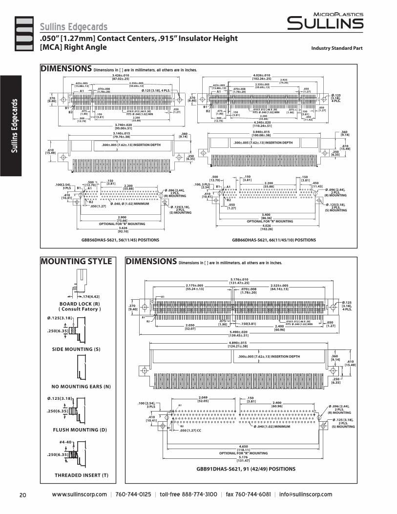
MOUNTING STYLE
DIMENSIONS Dimensions in [ ] are in millimeters, all others are in inches.
GBB56DHAS-S621, 56(11/45) POSITIONS GBB66DHAS-S621, 66(11/45/10) POSITIONS
3.400 [86.36]OPTIONAL FOR "R" MOUNTING
2.900[73.66]
OPTIONAL FOR "R" MOUNTING3.626
[92.10]
.100[2.54],3 PLS
.410[10.41]
.050 [1.27] Ø .040, Ø [1.02] MINIMUM
Ø .096 [2.44], 2 PLS.
(R) MOUNTING
Ø .125[3.18], 2 PLS.
(S) MOUNTING
.610[15.49]
3.140±.015[79.76±.38]
.300±.005 [7.62±.13] INSERTION DEPTH
.360[9.14]
.250[6.35]
3.426±.010[87.02±.25]
.370[9.40]
3.740±.020[95.00±.51]
Ø.125 [3.18], 4 PLS.
4.026±.010[102.26±.25]
.370[9.40]
Ø.125 [3.18], 4 PLS.
4.340±.020[110.24±.51]
3.940±.015[100.08±.38]
.360[9.14]
.610[15.49]
.250[6.35]
.100, 3 PLS[2.54]
.410[10.41]
4.026[102.26]
A1
A1
A1
A1
B1
B1 B1
B1
B2 B2
B2B2
.150[3.81]
2.200[55.88]
.500[12.70]
.050[1.27]
.150[3.81]
.450[11.43]
.500[12.70]
.150[3.81]
2.200[55.88]
.450[11.43]
.050[1.27].150
[3.81]
.075[1.90]
.500[12.70]
.075[1.90] .150
[3.81] 2.200[55.88]
2.925[74.30]
.050[1.27]
2.350±.005[59.69±.13]
.070±.008[1.78±.20]
.625±.005[15.88±.13]
2.350±.005[59.69±.13]
.070±.008[1.78±.20]
.625±.005[15.88±.13]
2.200[55.88]
.150[3.81]
.075[1.90]
.050[1.27]
.500[12.70]
.018 X .012 [.46 X .30]FITS Ø .040 [1.02] MIN
.018 X .012 [.46 X .30]FITS Ø .040 [1.02] MIN
.300±.005 [7.62±.13] INSERTION DEPTH
Ø .096 [2.44], 2 PLS.
(R) MOUNTING
Ø .125[3.18], 2 PLS.
(S) MOUNTING
GBB91DHAS-S621, 91 (42/49) POSITIONS
4.650[118.11]
OPTIONAL FOR "R" MOUNTING5.176
[131.47]
.050 [1.27] CC
.410[10.41]
.100 [2.54],3 PLS
2.049[52.05]
.150[3.81] 2.400
[60.96] Ø .096 [2.44], 2 PLS.
(R) MOUNTING
Ø .125 [3.18], 2 PLS.
(S) MOUNTINGØ .040 [1.02] MINIMUM
4.890±.015[124.21±.38]
.360[9.14]
.610[15.49]
.250[6.35]
.300±.005 [7.62±.13] INSERTION DEPTH
5.176±.010[131.47±.25]
Ø.125[3.18], 4 PLS.
5.490±.020[139.45±.51]
A1
.370[9.40]
B2
B1
B2B1
A1
2.175±.005[55.24 ±.13]
2.050[52.07]
.075[1.90] .150[3.81]
2.400[60.96]
2.525±.005[64.14±.13].070±.008
[1.78±.20]
.050[1.27]
.018 X .012 [.46 X .30]FITS Ø .040 [1.02] MIN
THREADED INSERT (T)
FLUSH MOUNTING (D)
NO MOUNTING EARS (N)
#4-40
SIDE MOUNTING (S)
Ø.125[3.18]
.250[6.35]
BOARD LOCK (R) ( Consult Fatory )
Ø.125[3.18]
.250[6.35]
.174[4.42]
.250[6.35]
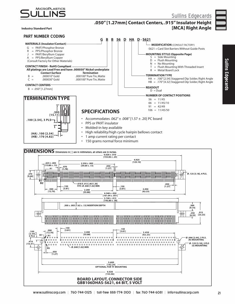
.050” [1.27mm] Contact Centers, .915” Insulator Height[MCA] Right Angle Industry Standard Part
DIMENSIONS Dimensions in [ ] are in millimeters, all others are in inches.
21www.sullinscorp.com | 760-744-0125 | toll-free 888-774-3100 | fax 760-744-6081 | [email protected]
Sullins EdgecardsSullins Edgecards
DIMENSIONS Dimensions in [ ] are in millimeters, all others are in inches.
.370[9.40]
.625 ± .005[15.88 ± .13]
6.026 ± .010[153.06 ± .25]
2.350 ± .005[59.69 ± .13] .050
[1.27] .070[1.78]
.150[3.81]
.150[3.81]
A1
.500[12.70]
.018 X .012 [.46 X .30]FITS Ø .040 [1.02] MIN
4.925[125.10]
2.450[62.23]
.050[1.27]
2.200[55.88] 6.340 ± .020
[161.04 ± .051] 5.740 ± .015[145.80 ± .38]
.300 ± .005 [7.62 ± .13] INSERTION DEPTH
Ø .125 [3.18], 4 PLS.
.360[9.14]
.915[23.23]
.250[6.35]
.150[3.81] .150
[3.81]
A1B1
B2
.500[12.70] 2.200
[55.88]
.050[1.27]
Ø .040 [1.02] MIN
.100[2.54], 3 PLS
.410[10.41]
2.450[62.23]
5.600[142.24]
OPTIONAL FOR 'R' MOUNTING
6.026[153.06]
BOARD LAYOUT, CONNECTOR SIDEGBB106DHAS-S621, 64 BIT, 5 VOLT
B1B2
Ø .096 [2.44], 2 PLS.(R) MOUNTING
Ø .125 [3.18], 2 PLS(S) MOUNTING
TERMINATION TYPE
SPECIFICATIONSAccommodates .062” ±• .008” [1.57 ± .20] PC boardPPS or PA9T insulator• Molded-in key available• High reliability/high cycle hairpin bellows contact• 1 amp current rating• per contact150 grams normal force minimum•
.595[15.11]
.100 [2.54], 3 PLS
(HA) .100 [2.54](HB) .170 [4.82]
PART NUMBER CODING
.050” [1.27mm] Contact Centers, .915” Insulator HeightIndustry Standard Part [MCA] Right Angle
MATERIALS (Insulator/Contact)G = PA9T/Phosphor BronzeR = PPS/Phosphor BronzeJ = PA9T/Beryllium CopperA = PPS/Beryllium Copper
(Consult Factory for Other Materials)
CONTACT CENTERSB = .050” [1.27mm]
NUMBER OF CONTACT POSITIONS 56 = 11/45 66 = 11/45/10 91 = 42/49106 = 11/45/50
READOUTD = Dual
S = Side MountingD = Flush MountingN = No MountingT = Flush Mounting With Threaded InsertR = Metal Board Lock
TERMINATION TYPEHA = .100” [2.54] Staggered Dip Solder, Right AngleHB = .170” [4.32] Staggered Dip Solder, Right Angle
-S621 = Card Slot Barriers Without Guide PostsMODIFICATION (CONSULT FACTORY)
MOUNTING STYLE (Opposite Page)
G B B 56 D HA D - S621
CONTACT FINISH - RoHS CompliantAll platings are Lead Free and have .000050” Nickel underplate
Contact Surface TerminationB = .000010” Gold .000100” Pure Tin, MatteC = .000030” Gold .000100” Pure Tin, Matte
www.sullinscorp.com | 760-744-0125 | toll-free 888-774-3100 | fax 760-744-6081 | [email protected]
Sullins EdgecardsSu
llins
Edg
ecar
ds
.370[9.40]3.940[100.08]
3.626[92.10]
2.550[64.77]
.250[6.35]
.078[1.98] GUIDE POST
.625[15.88]
.150[3.81]
.610[15.49]
49 POS.11 POS.
2.400[60.96].500[12.70]
2.525[64.14]
.070[1.78]
3.340[84.84]
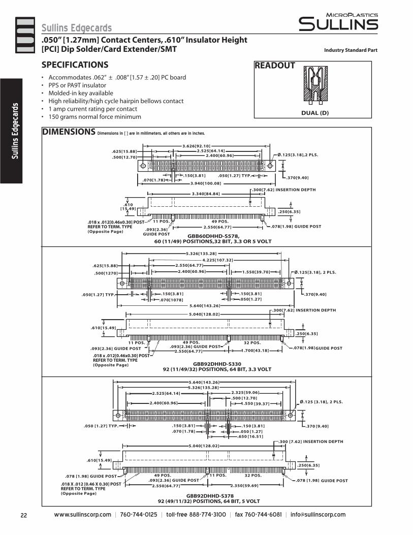
GBB60DHHD-S578,60 (11/49) POSITIONS,32 BIT, 3.3 OR 5 VOLT
.093[2.36]GUIDE POST
5.640[143.26]
5.326[135.28]
Ø.125[3.18], 2 PLS.
.370[9.40]
.250[6.35]
1.700[43.18]
[15.49].610
2.550[64.77]
49 POS.11 POS. 32 POS.
.093[2.36] GUIDE POST .078[1.98] GUIDE POST.093[2.36] GUIDE POST
.150[3.81].150[3.81]
.500[1270] 2.400[60.96] 1.550[39.70]
.625[15.88] 2.550[64.77]4.225[107.32]
.070[1078] .050[1.27]
5.040[128.02]
GBB92DHHD-S33092 (11/49/32) POSITIONS, 64 BIT, 3.3 VOLT
[135.28]5.326[143.26]5.640
.050 [1.27] TYP. [9.40].370
.250[6.35]
[64.77]2.550 [59.69]2.350
[15.49].610
49 POS. 11 POS. 32 POS..093[2.36] GUIDE POST .078 [1.98] GUIDE POST
.078 [1.98] GUIDE POST
[3.81].150[3.81].150
[60.96]2.400[12.70].500
[39.37]1.550
[64.14]2.525
[16.51].650
[59.06]2.325
[1.78].070 [1.27].050
.300 [7.62] INSERTION DEPTH5.040[128.02]
GBB92DHHD-S37892 (49/11/32) POSITIONS, 64 BIT, 5 VOLT
.018 x .012[0.46x0.30] POSTREFER TO TERM. TYPE(Opposite Page)
.018 X .012 [0.46 X 0.30] POSTREFER TO TERM. TYPE(Opposite Page)
.018 x .012[0.46x0.30] POSTREFER TO TERM. TYPE(Opposite Page)
Ø.125[3.18],2 PLS.
Ø.125 [3.18], 2 PLS.
.300[7.62] INSERTION DEPTH
.300[7.62] INSERTION DEPTH
.050[1.27] TYP.
.050[1.27] TYP.
READOUT
DUAL (D)
SPECIFICATIONSAccommodates .062” • ± .008” [1.57 ± .20] PC boardPPS or PA9T insulator• Molded-in key available• High reliability/high cycle hairpin bellows contact• 1 amp current rating• per contact150 grams normal force minimum•
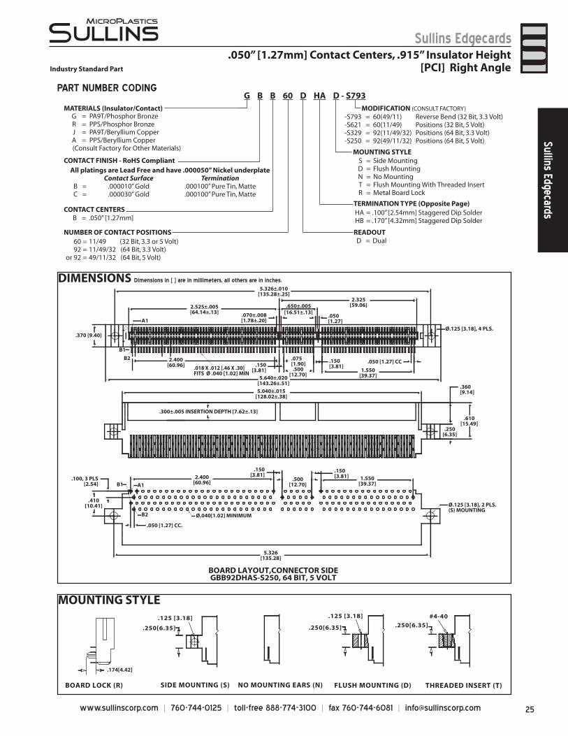
.050” [1.27mm] Contact Centers, .610” Insulator Height [PCI] Dip Solder/Card Extender/SMT Industry Standard Part
DIMENSIONS Dimensions in [ ] are in millimeters, all others are in inches.
23www.sullinscorp.com | 760-744-0125 | toll-free 888-774-3100 | fax 760-744-6081 | [email protected]
Sullins EdgecardsSullins Edgecards
MOUNTING STYLE
TERMINATION TYPE
STAGGERED DIP SOLDER(HH)
CARD EXTENDER (HR)
SURFACE MOUNT(HF)
DIP SOLDER(HL)
.100 [2.54], 3 PLS.
[4.06].160
[6.35].250
[3.18].125
[2.54].100
DIP SOLDER(HN)
Accommodates.062 [1.57] PCB
.160[4.06]
.125 [3.18]
.100 ± .025[2.54 ± .64]
FLUSH MOUNTINGWITH THREADED INSERT
(T)FLUSH MOUNTING
(D)NO MOUNTING EARS
(N)
#4-40 Ø.125 [3.18]
STRADDLE MOUNT (Q)Formerly (Z)
METAL BOARD LOCK (R)
.188[4.78]
.062[1.57]
.360[9.14]
.318[8.08]
.128[3.25]
.440[11.18]
Ø.078[1.98].250[6.35]
.134[3.40].025[0.64]
.250[6.35]
FOR PC BOARD LAYOUTS REFER TO www.sullinscorp.com
.050” [1.27mm] Contact Centers, .610” Insulator HeightIndustry Standard Part [PCI] Dip Solder/Card Extender/SMT
PART NUMBER CODING
MATERIALS (Insulator/Contact)
CONTACT CENTERSB = .050” [1.27mm]
NUMBER OF CONTACT POSITIONS 60 = 11/49 (32 Bit, 3.3 or 5 Volt) 92 = 11/49/32 (64 Bit, 3.3 Volt)or 92 = 49/11/32 (64 Bit, 5 Volt)
READOUTD = Dual
MOUNTING STYLED = Flush MountingN = No MountingT = Flush Mounting With Threaded InsertQ = Straddle Mount (Card Extender Only)R = Metal Boardlocks
TERMINATION TYPEHH = Staggered Dip SolderHR = Card ExtenderHF = Surface MountHL = .250” [6.35mm] x .160” [4.06mm] Dip SolderHN = .100” [2.54mm] x .125” [3.18mm] Dip Solder(REPLACES TERMINATIONS: CH, CR, CF, CL, CN)
PCI WITH GUIDE POSTS*-S578 = 60 (11/49) Positions(32 Bit, 3.3 or 5 Volt) -S330 = 92 (11/49/32) Positions(64 Bit, 3.3 Volt) -S378 = 92 (49/11/32) Positions(64 Bit, 5 Volt)PCI WITHOUT GUIDE POSTS*-S621 = 60 (11/49) Positions(32 Bit, 3.3 or 5 Volt) -S329 = 92 (11/49/32) Positions(64 Bit, 3.3 Volt) -S250 = 92 (49/11/32) Positions(64 Bit, 5 Volt)* Turn connector or board 1800 to switch from 3.3 to 5 volt
MODIFICATION (CONSULT FACTORY)G = PA9T/Phosphor BronzeR = PPS/Phosphor BronzeJ = PA9T/Beryllium CopperA = PPS/Beryllium Copper
(Consult Factory for Other Materials)
G B B 60 D HH D - S578
CONTACT FINISH - RoHS Compliant All platings are Lead Free and have .000050” Nickel underplate
Contact Surface TerminationB = .000010” Gold .000100” Pure Tin, MatteC = .000030” Gold .000100” Pure Tin, Matte
www.sullinscorp.com | 760-744-0125 | toll-free 888-774-3100 | fax 760-744-6081 | [email protected]
Sullins EdgecardsSu
llins
Edg
ecar
ds
TERMINATION TYPE
DIMENSIONS Dimensions in [ ] are in millimeters, all others are in inches.
DIMENSIONS Dimensions in [ ] are in millimeters, all others are in inches.
Ø.040 [1.02] MINIMUM
.370[9.40]
A1
B1
A1
3.626±.010[92.10±0.25]
B1
B2
B2
.625±.005[15.88±0.13]
2.525±.005[64.14±0.13]
.075[1.90] .150
[3.81]
3.940±.020[100.08±.51]
.300±.005 [7.62±.13] INSERTION DEPTH
3.340±.015[84.84±.38]
.250[6.35]
.610[15.49]
Ø.125 [3.18], 2 PLS.
(S) MOUNTING
.100 [2.54]3 PLS
.500[12.70] 2.400
[60.96]
.150[3.81]
.050 [1.27] CC.
.070±.008[1.78±.20]
.410[10.41]
Ø.125 [3.18], 4 PLS.
.018 x .012 POST[.46 x .30]
.360[9.14]
.500[12.70]
2.400[60.96]
.050 [1.27] CC
BOARD LAYOUT,CONNECTOR SIDEGBB60DHAS-S621. 32 BIT, 5 VOLT
3.626[92.10]
OPTIONAL FOR 'R' MOUNTING
Ø.104 [2.64], 2 PLS.
(R) MOUNTING
3.626[92.10]
1.550[39.37]
Ø.040[1.02] MINIMUM
.370 [9.40]
A1
B1
A1
5.326±.010[135.28±.25]
B1
B2
B2
5.326[135.28]
.625±.005[15.88±.13]
2.550±.005[64.77±.13]
.075[1.90] .150
[3.81]
5.640±.020[143.26±.51]
.300±.005 INSERTION DEPTH [7.62±.13]
5.040±.015[128.02±.38]
.100 [2.54],3 PLS
.500[12.70] 2.400
[60.96]
.150[3.81]
.050 [1.27] CC.
.070±.008[1.78±.20]
.410[10.41]
.018 x .012 [.46 x .30] POST
Ø.125 [3.18], 4 PLS.
.250[6.35]
.610[15.49]
.360[9.14]
Ø.125 [3.18], 2 PLS.(S) MOUNTING
.075[1.90] .150
[3.81]
.050[1.27]
.500[12.70]
2.400[60.96]
1.550[39.37]
4.225[107.32]
.050 [1.27] CC
.150[3.81]
BOARD LAYOUT,CONNECTOR SIDEGBB92DHAS-S329, 64 BIT, 3.3 VOLT
4.700[119.38]
OPTIONAL FOR 'R' MOUNTING
Ø.104 [2.64], 2 PLS.(R) MOUNTING
.595[15.11]
.100, 3 PLS.
(HA) .100 [2.54](HB) .170 [4.82]
SPECIFICATIONSAccom• modates .062” ± .008”
[1.57 ± .20] PC boardPPS or PA9T insulator• Molded-in key available• High reliability/high cycle •
hairpin bellows contact1 amp current rating• per contact150 grams normal force •
minimum
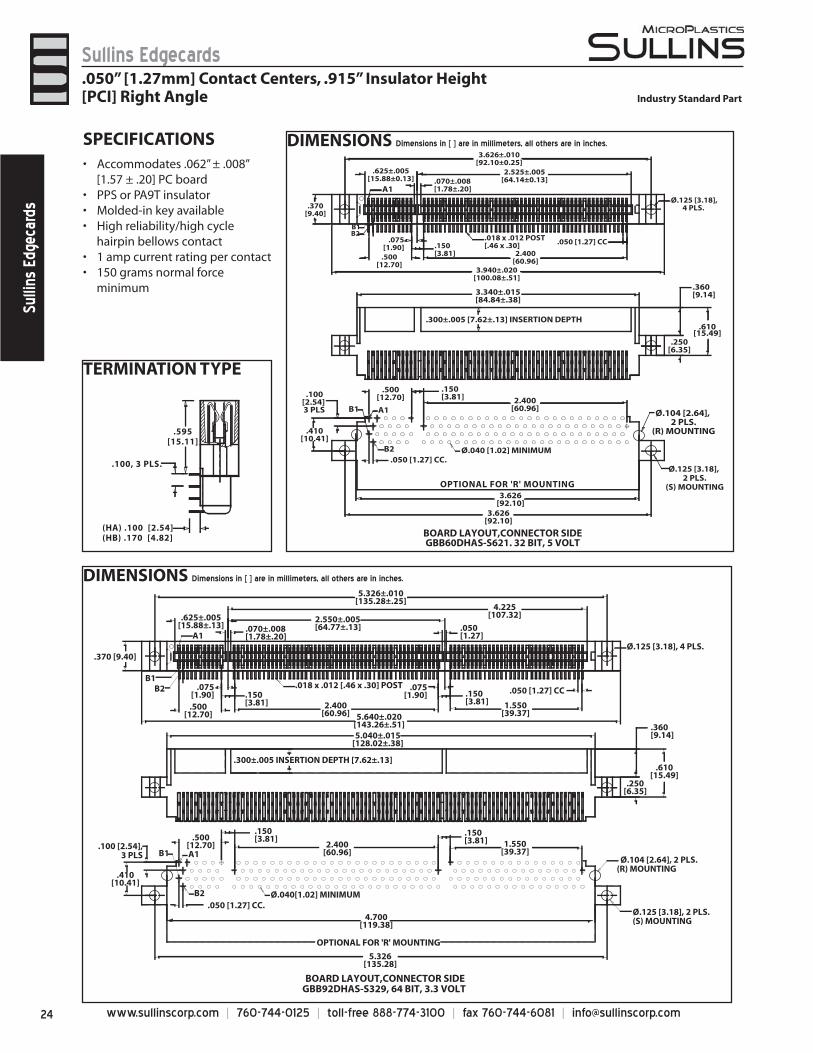
.050” [1.27mm] Contact Centers, .915” Insulator Height[PCI] Right Angle Industry Standard Part
25www.sullinscorp.com | 760-744-0125 | toll-free 888-774-3100 | fax 760-744-6081 | [email protected]
Sullins EdgecardsSullins Edgecards
MOUNTING STYLE
THREADED INSERT (T)FLUSH MOUNTING (D)NO MOUNTING EARS (N)
#4-40 .125 [3.18]
SIDE MOUNTING (S)
.125 [3.18]
.250[6.35]
BOARD LOCK (R)
.250[6.35] .250[6.35]
.174[4.42]
.050” [1.27mm] Contact Centers, .915” Insulator HeightIndustry Standard Part [PCI] Right Angle
PART NUMBER CODING
CONTACT CENTERSB = .050” [1.27mm]
NUMBER OF CONTACT POSITIONS READOUTD = Dual
MOUNTING STYLES = Side MountingD = Flush MountingN = No MountingT = Flush Mounting With Threaded InsertR = Metal Board Lock
HA = .100” [2.54mm] Staggered Dip SolderHB = .170” [4.32mm] Staggered Dip Solder
60 = 11/49 (32 Bit, 3.3 or 5 Volt)92 = 11/49/32 (64 Bit, 3.3 Volt)
or 92 = 49/11/32 (64 Bit, 5 Volt)
-S793 = 60(49/11) Reverse Bend (32 Bit, 3.3 Volt)-S621 = 60(11/49) Positions (32 Bit, 5 Volt)-S329 = 92(11/49/32) Positions (64 Bit, 3.3 Volt)-S250 = 92(49/11/32) Positions (64 Bit, 5 Volt)
MODIFICATION (CONSULT FACTORY)
TERMINATION TYPE (Opposite Page)
MATERIALS (Insulator/Contact)G = PA9T/Phosphor BronzeR = PPS/Phosphor BronzeJ = PA9T/Beryllium CopperA = PPS/Beryllium Copper
(Consult Factory for Other Materials)
All platings are Lead Free and have .000050” Nickel underplateContact Surface Termination
B = .000010” Gold .000100” Pure Tin, MatteC = .000030” Gold .000100” Pure Tin, Matte
BOARD LAYOUT,CONNECTOR SIDEGBB92DHAS-S250, 64 BIT, 5 VOLT
1.550[39.37]
Ø.040[1.02] MINIMUM
.370 [9.40]
A1
B1
A1B1
B2
B2
5.326[135.28]
.075[1.90].150
[3.81]5.640±.020
[143.26±.51]
.300±.005 INSERTION DEPTH [7.62±.13]
5.040±.015[128.02±.38]
.100, 3 PLS[2.54]
2.400[60.96]
.500[12.70]
.150[3.81]
.050 [1.27] CC.
.410[10.41]
Ø.125 [3.18], 4 PLS.
.250[6.35]
.610[15.49]
.360[9.14]
Ø.125 [3.18], 2 PLS.(S) MOUNTING
.150[3.81].500
[12.70]1.550
[39.37]
.050 [1.27] CC
.150[3.81]
5.326±.010[135.28±.25]
2.525±.005[64.14±.13]
.650±.005[16.51±.13].070±.008
[1.78±.20].050[1.27]
2.325[59.06]
2.400[60.96] .018 X .012 [.46 X .30]
FITS Ø .040 [1.02] MIN
DIMENSIONS Dimensions in [ ] are in millimeters, all others are in inches.
G B B 60 D HA D - S793
CONTACT FINISH - RoHS Compliant
www.sullinscorp.com | 760-744-0125 | toll-free 888-774-3100 | fax 760-744-6081 | [email protected]
Sullins EdgecardsSu
llins
Edg
ecar
ds
SPECIFICATIONS.050” Contact Center Spacing can repla• ce .100” CC parts
to double the number of contacts within the same areaBackwards Compatible with Daughter Card Side• Accommodates .062” ± .008” [1.57 ± .20] PC board• Contact Material: Beryllium Copper or Phosphor Bronze• Body Material: PPS/PA9T• UL Flammability: 94V-0• 3 amp current rating per contact• 75 grams minimum contact normal force• Voltage Rating: 125 VDC Minimum at sea level• Consult Factory for PC board layouts/technical drawings•
Bi-Level, .050”[1.27mm] / .100” [2.54] Contact CentersHigh Density, Card Extender, Dip Solder
DIMENSIONS
(A+.725[18.42]) ± .010[.25](A+.250[6.35]) ± .005[.13]
A ± .005[.13]
.050 [1.27] CC
(A+.050[1.27] ± .005[.13])
4X Ø.125 [3.18]
.025 [.64] SQ. POST
(A+.725[18.42]) ± .010[.25]
(A+.410[10.41]) ± .015[.38]
.303 [7.70]
.250 [6.35]
.553 [14.05]
.375 [9.53]
.901[22.89]
.060 [1.52] STANDOFF FOR
THRU HOLE (LT)
(A+.985[25.02]) ± .020[.51]
DAUGHTER CARD LAYOUT (2)DAUGHTER CARD LAYOUT (1)
HIGH DENSITY HIGH TEMPERATURE HIGH CYCLE HIGH RELIABILITY
DAUGHTER CARD LAYOUT 150 POSITION SHOWN
.100[2.54] TYP.
.050[1.27] TYP.B1 (A1 OPPOSITE)
B2 (A2 OPPOSITE)
DAUGHTER CARD LAYOUT 248 POSITION SHOWN
.100[2.54] TYP.
.050[1.27] TYP.B1 (A1 OPPOSITE)
B2 (A2 OPPOSITE)
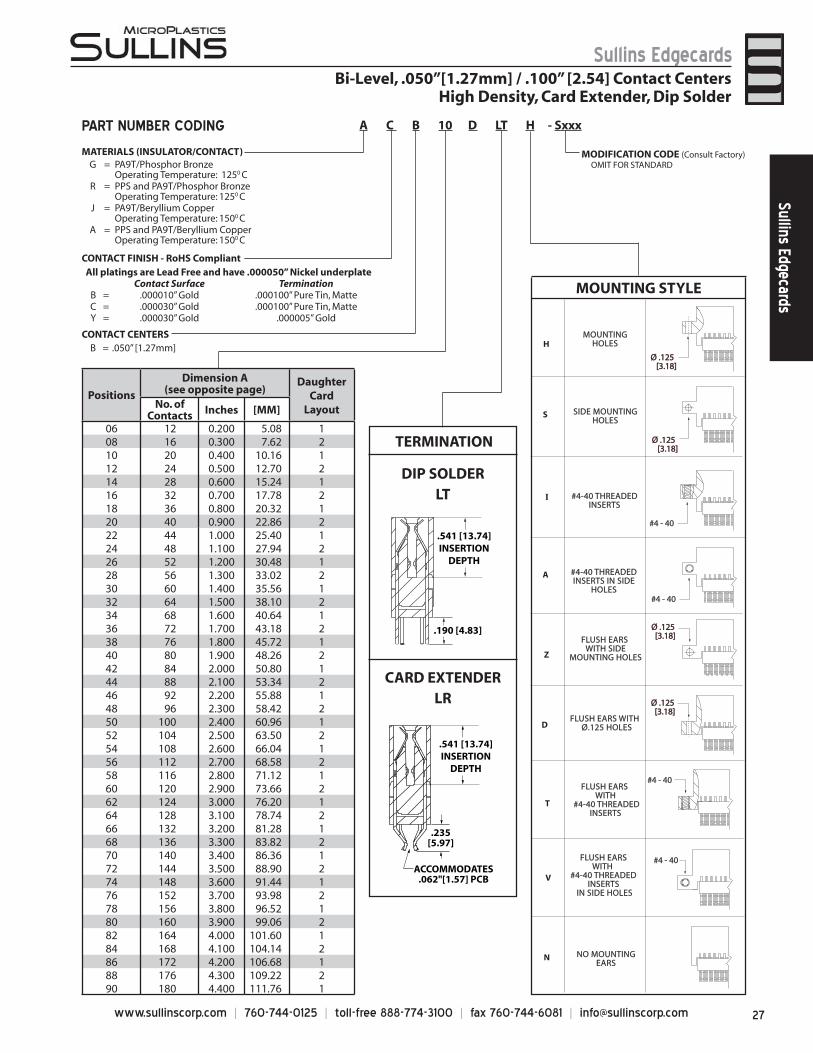
27www.sullinscorp.com | 760-744-0125 | toll-free 888-774-3100 | fax 760-744-6081 | [email protected]
Sullins EdgecardsSullins Edgecards
Bi-Level, .050”[1.27mm] / .100” [2.54] Contact CentersHigh Density, Card Extender, Dip Solder
PART NUMBER CODING
TERMINATION
DIP SOLDERLT
CARD EXTENDERLR
.541 [13.74]INSERTION
DEPTH
.235[5.97]
ACCOMMODATES.062"[1.57] PCB
CONTACT CENTERSB = .050” [1.27mm]
.541 [13.74]INSERTION
DEPTH
.190 [4.83]FLUSH EARS
WITH SIDEMOUNTING HOLES
FLUSH EARS WITH Ø.125 HOLES
FLUSH EARS WITH
#4-40 THREADED INSERTS
IN SIDE HOLES
#4-40 THREADEDINSERTS IN SIDE
HOLES
#4-40 THREADEDINSERTS
FLUSH EARS WITH
#4-40 THREADEDINSERTS
MOUNTINGHOLES
SIDE MOUNTINGHOLES
NO MOUNTINGEARS
Z
D
T
V
H
S
I
A
N
ØØ ..112255 [[33..1188]]
ØØ ..112255 [[33..1188]]
#4 - 40
#4 - 40
ØØ ..112255 [[33..1188]]
ØØ ..112255 [[33..1188]]
#4 - 40
#4 - 40
MOUNTING STYLE
Positions
Dimension A(see opposite page)
Daughter Card
LayoutNo. ofContacts Inches [MM]
06 12 0.200 5.08 108 16 0.300 7.62 210 20 0.400 10.16 112 24 0.500 12.70 214 28 0.600 15.24 116 32 0.700 17.78 218 36 0.800 20.32 120 40 0.900 22.86 222 44 1.000 25.40 124 48 1.100 27.94 226 52 1.200 30.48 128 56 1.300 33.02 230 60 1.400 35.56 132 64 1.500 38.10 234 68 1.600 40.64 136 72 1.700 43.18 238 76 1.800 45.72 140 80 1.900 48.26 242 84 2.000 50.80 144 88 2.100 53.34 246 92 2.200 55.88 148 96 2.300 58.42 250 100 2.400 60.96 152 104 2.500 63.50 254 108 2.600 66.04 156 112 2.700 68.58 258 116 2.800 71.12 160 120 2.900 73.66 262 124 3.000 76.20 164 128 3.100 78.74 266 132 3.200 81.28 168 136 3.300 83.82 270 140 3.400 86.36 172 144 3.500 88.90 274 148 3.600 91.44 176 152 3.700 93.98 278 156 3.800 96.52 180 160 3.900 99.06 282 164 4.000 101.60 184 168 4.100 104.14 286 172 4.200 106.68 188 176 4.300 109.22 290 180 4.400 111.76 1
MATERIALS (INSULATOR/CONTACT)
All platings are Lead Free and have .000050” Nickel underplateContact Surface Termination
B = .000010” Gold .000100” Pure Tin, MatteC = .000030” Gold .000100” Pure Tin, MatteY = .000030” Gold .000005” Gold
A C B 10 D LT H - Sxxx
MODIFICATION CODE (Consult Factory) OMIT FOR STANDARDG = PA9T/Phosphor Bronze
Operating Temperature: 1250 C R = PPS and PA9T/Phosphor Bronze
Operating Temperature: 1250 CJ = PA9T/Beryllium Copper
Operating Temperature: 1500 CA = PPS and PA9T/Beryllium Copper
Operating Temperature: 1500 C
CONTACT FINISH - RoHS Compliant
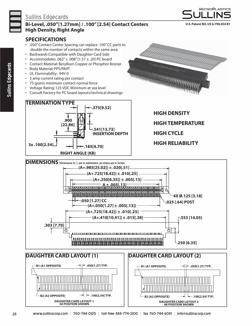
www.sullinscorp.com | 760-744-0125 | toll-free 888-774-3100 | fax 760-744-6081 | [email protected]
Sullins EdgecardsSu
llins
Edg
ecar
ds
DIMENSIONS Dimensions in [ ] are in millimeters, all others are in inches.
TERMINATION TYPE
RIGHT ANGLE (KB)
3x .100[2.54]
.900[22.86]
.375[9.52]
.541[13.73]INSERTION DEPTH
.185[4.70]
DAUGHTER CARD LAYOUT (1)
DAUGHTER CARD LAYOUT 150 POSITION SHOWN
.100[2.54] TYP.
.050[1.27] TYP.B1 (A1 OPPOSITE)
B2 (A2 OPPOSITE)
Bi-Level, .050”[1.27mm] / .100” [2.54] Contact CentersHigh Density, Right Angle
DAUGHTER CARD LAYOUT (2)
(A+.985[25.02]) ± .020[.51]
(A+.725[18.42]) ± .010[.25]
(A+.250[6.35]) ± .005[.13]A ± .005[.13]
.050 [1.27] CC(A+.050[1.27] ± .005[.13])
4X Ø.125 [3.18]
.025 [.64] POST
(A+.725[18.42]) ± .010[.25](A+.410[10.41]) ± .015[.38]
.303 [7.70]
.250 [6.35]
.553 [14.05]
U.S. Patent NO. US 6,790,054 B1
SPECIFICATIONS.050” Contact Center Spacing can replace .100” CC parts to •
double the number of contacts within the same areaBackwards Compatible with Daughter Card Side• Accommodates .062” ± .008” [1.57 ± .20] PC board• Contact Material: Beryllium Copper or Phosphor Bronze• Body Material: PPS/PA9T• UL Flammability: 94V-0• 3 amp current rating per contact• 75 grams minimum contact normal force• Voltage Rating: 125 VDC Minimum at sea level• Consult Factory for PC board layouts/technical drawings•
DAUGHTER CARD LAYOUT 248 POSITION SHOWN
.100[2.54] TYP.
.050[1.27] TYP.B1 (A1 OPPOSITE)
B2 (A2 OPPOSITE)
o
HIGH DENSITY
HIGH TEMPERATURE
HIGH CYCLE
HIGH RELIABILITY
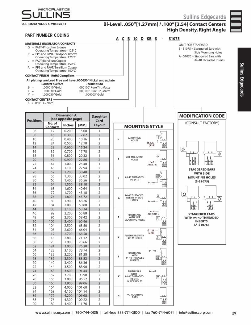
29www.sullinscorp.com | 760-744-0125 | toll-free 888-774-3100 | fax 760-744-6081 | [email protected]
Sullins EdgecardsSullins Edgecards
Bi-Level, .050”[1.27mm] / .100” [2.54] Contact CentersHigh Density, Right Angle
U.S. Patent NO. US 6,790,054 B1
PART NUMBER CODING
MATERIALS (INSULATOR/CONTACT) OMIT FOR STANDARDS - S1075 = Staggered Ears with Side Mounting HolesA - S1076 = Staggered Ears with #4-40 Threaded Inserts
All platings are Lead Free and have .000050” Nickel underplateContact Surface Termination
B = .000010” Gold .000100” Pure Tin, MatteC = .000030” Gold .000100” Pure Tin, MatteY = .000030” Gold .000005” Gold
CONTACT CENTERSB = .050” [1.27mm]
G = PA9T/Phosphor BronzeOperating Temperature: 1250 C
R = PPS and PA9T/Phosphor BronzeOperating Temperature: 1250 C
J = PA9T/Beryllium CopperOperating Temperature: 1500 C
A = PPS and PA9T/Beryllium Copper Operating Temperature: 1500 C
#4 - 40
FLUSH EARS WITH SIDE
MOUNTING HOLES
FLUSH EARS WITH Ø.125 HOLES
FLUSH EARS WITH
#4-40 THREADED INSERTS
IN SIDE HOLES
#4-40 THREADEDINSERTS IN SIDE
HOLES
#4-40 THREADEDINSERTS
FLUSH EARS WITH
#4-40 THREADEDINSERTS
MOUNTINGHOLES
SIDE MOUNTINGHOLES
NO MOUNTINGEARS
Z
D
T
V
H
S
I
A
N
ØØ ..112255 [[33..1188]]
#4 - 40
#4 - 40
ØØ ..112255 [[33..1188]]
#4 - 40
22 xx ØØ ..112255 [[33..1188]]
22 xx ØØ..112255 [[33..1188]]
MOUNTING STYLE(CONSULT FACTORY)
STAGGERED EARSWITH SIDE
MOUNTING HOLES(S-S1075)
STAGGERED EARSWITH #4-40 THREADED
INSERTS(A-S1076)
MODIFICATION CODEPositions
Dimension A(see opposite page)
Daughter Card
LayoutNo. ofContacts Inches [MM]
06 12 0.200 5.08 108 16 0.300 7.62 210 20 0.400 10.16 112 24 0.500 12.70 214 28 0.600 15.24 116 32 0.700 17.78 218 36 0.800 20.32 120 40 0.900 22.86 222 44 1.000 25.40 124 48 1.100 27.94 226 52 1.200 30.48 128 56 1.300 33.02 230 60 1.400 35.56 132 64 1.500 38.10 234 68 1.600 40.64 136 72 1.700 43.18 238 76 1.800 45.72 140 80 1.900 48.26 242 84 2.000 50.80 144 88 2.100 53.34 246 92 2.200 55.88 148 96 2.300 58.42 250 100 2.400 60.96 152 104 2.500 63.50 254 108 2.600 66.04 156 112 2.700 68.58 258 116 2.800 71.12 160 120 2.900 73.66 262 124 3.000 76.20 164 128 3.100 78.74 266 132 3.200 81.28 168 136 3.300 83.82 270 140 3.400 86.36 172 144 3.500 88.90 274 148 3.600 91.44 176 152 3.700 93.98 278 156 3.800 96.52 180 160 3.900 99.06 282 164 4.000 101.60 184 168 4.100 104.14 286 172 4.200 106.68 188 176 4.300 109.22 290 180 4.400 111.76 1
A C B 10 D KB S - S1075
CONTACT FINISH - RoHS Compliant
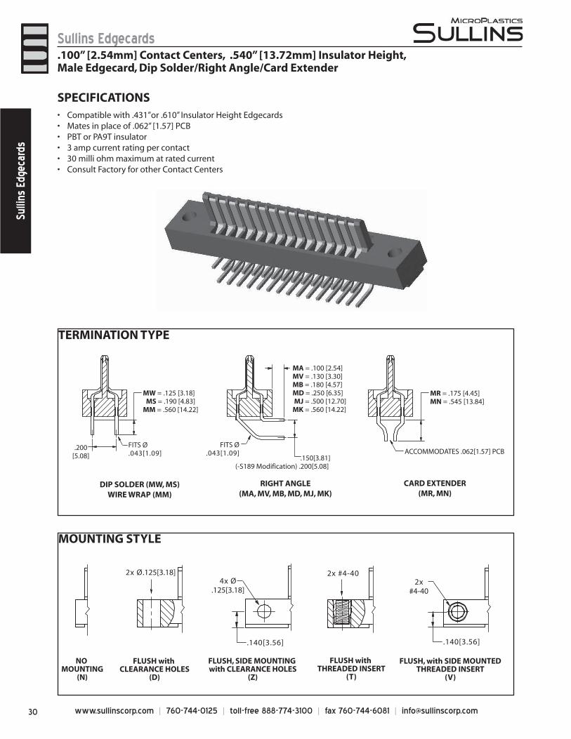
www.sullinscorp.com | 760-744-0125 | toll-free 888-774-3100 | fax 760-744-6081 | [email protected]
Sullins EdgecardsSu
llins
Edg
ecar
ds
SPECIFICATIONSCo• mpatible with .431”or .610” Insulator Height EdgecardsMates in place of .062” [1.57] PCB• PBT or PA9T insulator • 3 amp current rating per contact• 30 milli ohm maximum at rated current• Consult Factory for other Contact Centers•
.100” [2.54mm] Contact Centers, .540” [13.72mm] Insulator Height,Male Edgecard, Dip Solder/Right Angle/Card Extender
TERMINATION TYPE
.200[5.08]
MW = .125 [3.18] MS = .190 [4.83]MM = .560 [14.22]
.150[3.81](-S189 Modification) .200[5.08]
MA = .100 [2.54]MV = .130 [3.30]MB = .180 [4.57]MD = .250 [6.35] MJ = .500 [12.70]MK = .560 [14.22]
MR = .175 [4.45]MN = .545 [13.84]
ACCOMMODATES .062[1.57] PCB
DIP SOLDER (MW, MS)WIRE WRAP (MM)
RIGHT ANGLE(MA, MV, MB, MD, MJ, MK)
CARD EXTENDER(MR, MN)
FITS Ø.043[1.09]
FITS Ø.043[1.09]
MOUNTING STYLE
FLUSH with CLEARANCE HOLES
(D)
FLUSH, with SIDE MOUNTEDTHREADED INSERT
(V)
FLUSH with THREADED INSERT
(T)
FLUSH, SIDE MOUNTING with CLEARANCE HOLES
(Z)
NO MOUNTING
(N)
2x Ø.125[3.18]4x Ø
.125[3.18]
.140[3.56]
2x #4-402x
#4-40
.140[3.56]
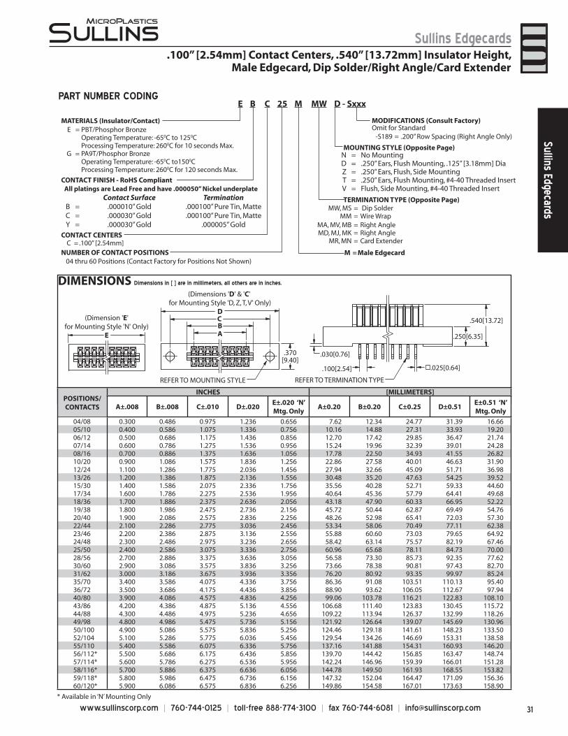
31www.sullinscorp.com | 760-744-0125 | toll-free 888-774-3100 | fax 760-744-6081 | [email protected]
Sullins EdgecardsSullins Edgecards
DIMENSIONS Dimensions in [ ] are in millimeters, all others are in inches.
.100” [2.54mm] Contact Centers, .540” [13.72mm] Insulator Height, Male Edgecard, Dip Solder/Right Angle/Card Extender
ABC
(Dimensions 'D' & 'C' for Mounting Style 'D, Z, T, V' Only)
D
REFER TO MOUNTING STYLE
.370[9.40]
.030[0.76]
.025[0.64]
REFER TO TERMINATION TYPE
.540[13.72]
.250[6.35]
.100[2.54]
(Dimension 'E'for Mounting Style 'N' Only)
E
* Available in ‘N’ Mounting Only
PART NUMBER CODING
MATERIALS (Insulator/Contact)
CONTACT CENTERSC = .100” [2.54mm]
NUMBER OF CONTACT POSITIONS
MW, MS = Dip SolderMM = Wire Wrap
MA, MV, MB = Right AngleMD, MJ, MK = Right Angle
MR, MN = Card Extender
MODIFICATIONS (Consult Factory) Omit for Standard
MOUNTING STYLE (Opposite Page)
TERMINATION TYPE (Opposite Page)
04 thru 60 Positions (Contact Factory for Positions Not Shown)
E = PBT/Phosphor BronzeOperating Temperature: -650C to 1250CProcessing Temperature: 2600C for 10 seconds Max.
G = PA9T/Phosphor BronzeOperating Temperature: -650C to1500CProcessing Temperature: 2600C for 120 seconds Max.
All platings are Lead Free and have .000050” Nickel underplate Contact Surface Termination
B = .000010” Gold .000100” Pure Tin, MatteC = .000030” Gold .000100” Pure Tin, MatteY = .000030” Gold .000005” Gold
CONTACT FINISH - RoHS Compliant
E B C 25 M MW D - Sxxx
N = No MountingD = .250” Ears, Flush Mounting, .125” [3.18mm] DiaZ = .250” Ears, Flush, Side MountingT = .250” Ears, Flush Mounting, #4-40 Threaded InsertV = Flush, Side Mounting, #4-40 Threaded Insert
M = Male Edgecard
-S189 = .200” Row Spacing (Right Angle Only)
POSITIONS/CONTACTS
INCHES [MILLIMETERS]
A±.008 B±.008 C±.010 D±.020E±.020 ‘N’ Mtg. Only
A±0.20 B±0.20 C±0.25 D±0.51E±0.51 ‘N’ Mtg. Only
04/08 0.300 0.486 0.975 1.236 0.656 7.62 12.34 24.77 31.39 16.6605/10 0.400 0.586 1.075 1.336 0.756 10.16 14.88 27.31 33.93 19.2006/12 0.500 0.686 1.175 1.436 0.856 12.70 17.42 29.85 36.47 21.7407/14 0.600 0.786 1.275 1.536 0.956 15.24 19.96 32.39 39.01 24.2808/16 0.700 0.886 1.375 1.636 1.056 17.78 22.50 34.93 41.55 26.8210/20 0.900 1.086 1.575 1.836 1.256 22.86 27.58 40.01 46.63 31.9012/24 1.100 1.286 1.775 2.036 1.456 27.94 32.66 45.09 51.71 36.9813/26 1.200 1.386 1.875 2.136 1.556 30.48 35.20 47.63 54.25 39.5215/30 1.400 1.586 2.075 2.336 1.756 35.56 40.28 52.71 59.33 44.6017/34 1.600 1.786 2.275 2.536 1.956 40.64 45.36 57.79 64.41 49.6818/36 1.700 1.886 2.375 2.636 2.056 43.18 47.90 60.33 66.95 52.2219/38 1.800 1.986 2.475 2.736 2.156 45.72 50.44 62.87 69.49 54.7620/40 1.900 2.086 2.575 2.836 2.256 48.26 52.98 65.41 72.03 57.3022/44 2.100 2.286 2.775 3.036 2.456 53.34 58.06 70.49 77.11 62.3823/46 2.200 2.386 2.875 3.136 2.556 55.88 60.60 73.03 79.65 64.9224/48 2.300 2.486 2.975 3.236 2.656 58.42 63.14 75.57 82.19 67.4625/50 2.400 2.586 3.075 3.336 2.756 60.96 65.68 78.11 84.73 70.0028/56 2.700 2.886 3.375 3.636 3.056 56.58 73.30 85.73 92.35 77.6230/60 2.900 3.086 3.575 3.836 3.256 73.66 78.38 90.81 97.43 82.7031/62 3.000 3.186 3.675 3.936 3.356 76.20 80.92 93.35 99.97 85.2435/70 3.400 3.586 4.075 4.336 3.756 86.36 91.08 103.51 110.13 95.4036/72 3.500 3.686 4.175 4.436 3.856 88.90 93.62 106.05 112.67 97.9440/80 3.900 4.086 4.575 4.836 4.256 99.06 103.78 116.21 122.83 108.1043/86 4.200 4.386 4.875 5.136 4.556 106.68 111.40 123.83 130.45 115.7244/88 4.300 4.486 4.975 5.236 4.656 109.22 113.94 126.37 132.99 118.2649/98 4.800 4.986 5.475 5.736 5.156 121.92 126.64 139.07 145.69 130.9650/100 4.900 5.086 5.575 5.836 5.256 124.46 129.18 141.61 148.23 133.5052/104 5.100 5.286 5.775 6.036 5.456 129.54 134.26 146.69 153.31 138.5855/110 5.400 5.586 6.075 6.336 5.756 137.16 141.88 154.31 160.93 146.2056/112* 5.500 5.686 6.175 6.436 5.856 139.70 144.42 156.85 163.47 148.7457/114* 5.600 5.786 6.275 6.536 5.956 142.24 146.96 159.39 166.01 151.2858/116* 5.700 5.886 6.375 6.636 6.056 144.78 149.50 161.93 168.55 153.8259/118* 5.800 5.986 6.475 6.736 6.156 147.32 152.04 164.47 171.09 156.3660/120* 5.900 6.086 6.575 6.836 6.256 149.86 154.58 167.01 173.63 158.90
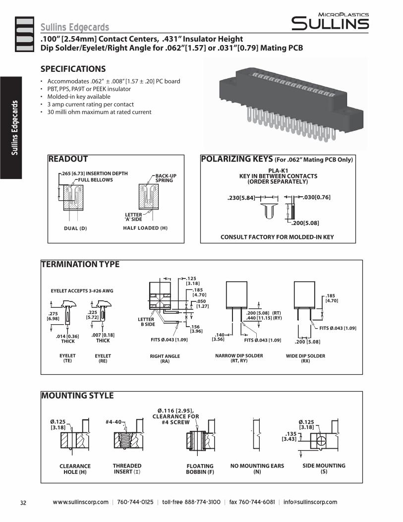
www.sullinscorp.com | 760-744-0125 | toll-free 888-774-3100 | fax 760-744-6081 | [email protected]
Sullins EdgecardsSu
llins
Edg
ecar
ds
MOUNTING STYLE
TERMINATION TYPE
READOUT POLARIZING KEYS (For .062” Mating PCB Only)
LETTER'A' SIDE
.265 [6.73] INSERTION DEPTH
DUAL (D)
FULL BELLOWS
HALF LOADED (H)
BACK-UPSPRING
.230[5.84] .030[0.76]
.200[5.08]
CONSULT FACTORY FOR MOLDED-IN KEY
PLA-K1KEY IN BETWEEN CONTACTS
(ORDER SEPARATELY)
EYELET ACCEPTS 3-#26 AWG
.225[5.72]
.014 [0.36] THICK
EYELET(TE)
EYELET(RE)
.275[6.98]
.007 [0.18]THICK
LETTER B SIDE
.185[4.70]
.156[3.96]
.125[3.18]
.050[1.27]
RIGHT ANGLE(RA)
FITS Ø.043 [1.09] .200 [5.08]
.185[4.70]
NARROW DIP SOLDER(RT, RY)
WIDE DIP SOLDER(RX)
.140[3.56]
.200 [5.08] (RT)
.440 [11.15] (RY)
FITS Ø.043 [1.09]
FITS Ø.043 [1.09]
Ø.125[3.18]
#4-40 Ø.125[3.18]
.135[3.43]
CLEARANCEHOLE (H)
THREADEDINSERT (I)
FLOATINGBOBBIN (F)
NO MOUNTING EARS(N)
SIDE MOUNTING(S)
Ø.116 [2.95],CLEARANCE FOR
#4 SCREW
SPECIFICATIONSAccommodate• s .062” ± .008” [1.57 ± .20] PC boardPBT, PPS, PA9T or PEEK insulator• Molded-in key available• 3 amp current rating• per contact30 milli ohm maximum at rated current•
.100” [2.54mm] Contact Centers, .431” Insulator HeightDip Solder/Eyelet/Right Angle for .062”[1.57] or .031”[0.79] Mating PCB
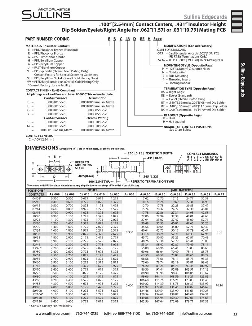
33www.sullinscorp.com | 760-744-0125 | toll-free 888-774-3100 | fax 760-744-6081 | [email protected]
Sullins EdgecardsSullins Edgecards
DIMENSIONS Dimensions in [ ] are in millimeters, all others are in inches.
MATERIALS (Insulator/Contact)
CONTACT CENTERSC = .100” [2.54mm]
NUMBER OF CONTACT POSITIONS
D = DualH = Half Loaded
H = .125”[3.18mm] Clearance HolesN = No MountingS = Side MountingI = Threaded InsertF = Floating Bobbin
RA = Right AngleRE = Eyelet (Standard)TE = Eyelet (Overall Plated Only)RT = .140”[3.56mm] x .200”[5.08mm] Dip SolderRY = .140”[3.56mm] x .440”[11.18mm] Dip SolderRX = .200”[5.08mm] x .185”[4.70mm] Dip Solder
OMIT FOR STANDARD -S13 = Card Extender Accepts .062”[1.57] PCB
(RE, RT, RY Terminations Only)-S734 = .031” ± .008” [.79 ± .20] Thick Mating PCB
MODIFICATIONS (Consult Factory)
* Consult Factory For Availability
READOUT (Opposite Page)
MOUNTING STYLE (Opposite Page)
TERMINATION TYPE (Opposite Page)
See Chart Below
E = PBT/Phosphor Bronze (Standard)R = PPS/Phosphor BronzeG = PA9T/Phosphor bronzeH = PBT/Beryllium CopperA = PPS/Beryllium CopperJ = PA9T/Beryllium Copper
*F = PPS/Spinodal (Overall Gold Plating Only)Consult Factory for Special Soldering Guidelines
*C = PPS/Beryllium Nickel (Overall Gold Plating Only)*W = PEEK/Beryllium Nickel (Overall Gold Plating Only) *Consult Factory for availability.
.100” [2.54mm] Contact Centers, .431” Insulator HeightDip Solder/Eyelet/Right Angle for .062”[1.57] or .031”[0.79] Mating PCB
PART NUMBER CODING
All platings are Lead Free and have .000050” Nickel underplate Contact Surface Termination
B = .000010” Gold .000100” Pure Tin, MatteC = .000030” Gold .000100” Pure Tin, MatteG = .000010” Gold .000005” GoldY = .000030” Gold .000005” Gold
Contact Surface Overall PlatingS = .000010” Gold .000010” GoldM = .000030” Gold .000010” GoldE = .000100” Pure Tin, Matte .000100” Pure Tin, Matte
Tolerances with PPS Insulator Material may vary slightly due to shrinkage differential; Consult Factory.
E B C 43 D RE H - Sxxx
A
D
B
E
FB 1 2 59 60 B
A 1 2 59 60 A
CONTACT MARKINGSB 1 2 3 . . . 58 59 60 BA 1 2 3 . . . 58 59 60 AC
REFER TOMOUNTINGSTYLE
REFER TO TERMINATION TYPE.100 [2.54] TYP.
.265 [6.73] INSERTION DEPTH
.431 [10.95]
.245 [6.22].025[0.64]
POSITIONS/CONTACTS
INCHES [MILLIMETERS]A±.008 B±.008 C±.015 D±.010 E±.020 F±.005 A±0.20 B±0.20 C±0.38 D±0.25 E±0.51 F±0.13
04/08* 0.300 0.500 0.675 0.975 1.275
0.330
7.62 12.70 17.15 24.77 32.39
8.38
05/10 0.400 0.600 0.775 1.075 1.375 10.16 15.24 19.69 27.31 34.9306/12 0.500 0.700 0.875 1.175 1.475 12.70 17.78 22.23 29.85 37.4707/14 0.600 0.800 0.975 1.275 1.575 15.24 20.32 24.77 32.39 40.0108/16 0.700 0.900 1.075 1.375 1.675 17.78 22.86 27.31 34.93 42.5510/20 0.900 1.100 1.275 1.575 1.875 22.86 27.94 32.39 40.01 47.6312/24 1.100 1.300 1.475 1.775 2.075 27.94 33.02 37.47 45.09 52.7113/26 1.200 1.400 1.575 1.875 2.175 30.48 35.56 40.01 47.63 55.2515/30 1.400 1.600 1.775 2.075 2.375 35.56 40.64 45.09 52.71 60.3317/34 1.600 1.800 1.975 2.275 2.575 40.64 45.72 50.17 57.79 65.4118/36 1.700 1.900 2.075 2.375 2.675 43.18 48.26 52.71 60.33 67.9519/38 1.800 2.000 2.175 2.475 2.775 45.72 50.80 55.25 62.87 70.4920/40 1.900 2.100 2.275 2.575 2.875 48.26 53.34 57.79 65.41 73.0322/44 2.100 2.300 2.475 2.775 3.075 53.34 58.42 62.87 70.49 78.1123/46* 2.200 2.400 2.575 2.875 3.175 55.88 60.96 65.41 73.03 80.6525/50 2.400 2.600 2.775 3.075 3.375 60.96 66.04 70.49 78.11 85.7326/52 2.500 2.700 2.875 3.175 3.475 63.50 68.58 73.03 80.65 88.2728/56 2.700 2.900 3.075 3.375 3.675 68.58 73.66 78.11 85.73 93.3530/60 2.900 3.100 3.275 3.575 3.875 73.66 78.74 83.19 90.81 98.4331/62 3.000 3.200 3.375 3.675 3.975 76.20 81.28 85.73 93.35 100.9735/70 3.400 3.600 3.775 4.075 4.375
0.400
86.36 91.44 95.89 103.51 111.13
10.16
36/72 3.500 3.700 3.875 4.175 4.475 88.90 93.98 98.43 106.05 113.6740/80 3.900 4.100 4.275 4.575 4.875 99.06 104.14 108.59 116.21 123.8343/86 4.200 4.400 4.575 4.875 5.175 106.68 111.76 116.21 123.83 131.4544/88 4.300 4.500 4.675 4.975 5.275 109.22 114.30 118.75 126.37 133.9949/98 4.800 5.000 5.175 5.475 5.775 121.92 127.00 131.45 139.07 146.6950/100 4.900 5.100 5.275 5.575 5.875 124.46 129.54 133.99 141.61 149.2352/104* 5.100 5.300 5.475 5.775 6.075 129.54 134.62 139.07 146.69 154.3160/120 5.900 6.100 6.275 6.575 6.875 149.86 154.94 159.39 167.01 174.6365/130 6.400 6.600 6.775 7.075 7.375 162.56 167.64 172.09 179.71 187.33
CONTACT FINISH - RoHS Compliant
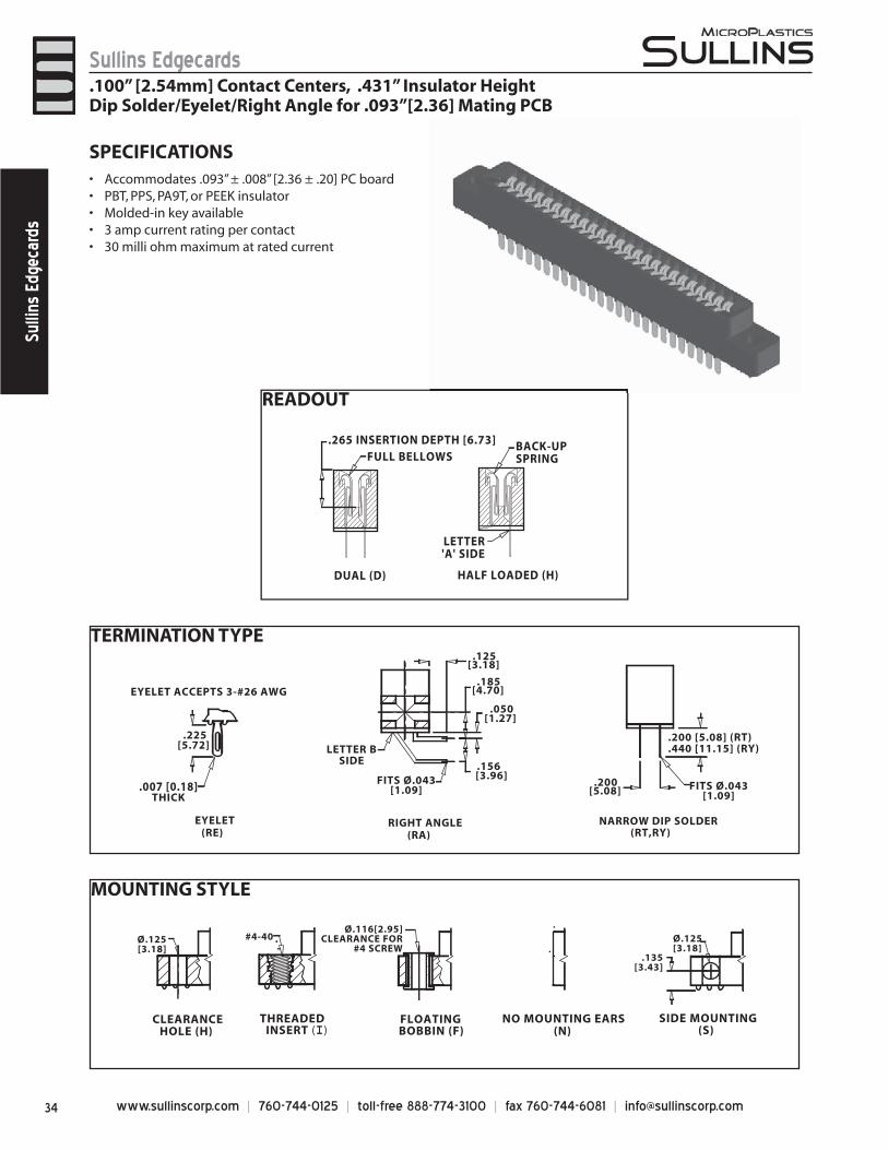
www.sullinscorp.com | 760-744-0125 | toll-free 888-774-3100 | fax 760-744-6081 | [email protected]
Sullins EdgecardsSu
llins
Edg
ecar
ds
TERMINATION TYPE
MOUNTING STYLE
READOUT
LETTER'A' SIDE
.265 INSERTION DEPTH [6.73]
DUAL (D)
FULL BELLOWS
HALF LOADED (H)
BACK-UPSPRING
EYELET ACCEPTS 3-#26 AWG
[5.72].225
EYELET (RE)
.007 [0.18] THICK
LETTER BSIDE
[4.70].185
[3.96].156
[3.18].125
[1.27].050
RIGHT ANGLE (RA)
FITS Ø.043[1.09]
NARROW DIP SOLDER (RT,RY)
[5.08].200
.200 [5.08] (RT)
.440 [11.15] (RY)
FITS Ø.043[1.09]
Ø.125[3.18]
CLEARANCEHOLE (H)
THREADEDINSERT (I)
FLOATINGBOBBIN (F)
NO MOUNTING EARS (N)
SIDE MOUNTING (S)
#4-40Ø.116[2.95]
CLEARANCE FOR#4 SCREW
Ø.125[3.18]
.135[3.43]
SPECIFICATIONSAccomm• odates .093” ± .008” [2.36 ± .20] PC boardPBT, PPS, PA9T, or PEEK insulator• Molded-in key available• 3 amp current rating• per contact30 milli ohm maximum at rated current•
.100” [2.54mm] Contact Centers, .431” Insulator HeightDip Solder/Eyelet/Right Angle for .093”[2.36] Mating PCB
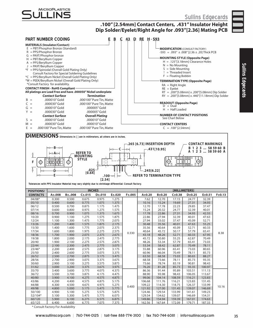
35www.sullinscorp.com | 760-744-0125 | toll-free 888-774-3100 | fax 760-744-6081 | [email protected]
Sullins EdgecardsSullins Edgecards
Tolerances with PPS Insulator Material may vary slightly due to shrinkage differential; Consult Factory.
DIMENSIONS Dimensions in [ ] are in millimeters, all others are in inches.
A
D
B
E
FB 1 2 59 60 B
A 1 2 59 60 A
CONTACT MARKINGSB 1 2 3 ... 58 59 60 B A 1 2 3 ... 58 59 60 A
CREFER TO
MOUNTING STYLE
REFER TO TERMINATION TYPE
.100 [2.54]
.265 [6.73] INSERTION DEPTH
[10.95].431
.245[6.22] .025[0.64]
PART NUMBER CODING
.100” [2.54mm] Contact Centers, .431” Insulator Height Dip Solder/Eyelet/Right Angle for .093”[2.36] Mating PCB
MATERIALS (Insulator/Contact)
CONTACT CENTERSC = .100” [2.54mm]
NUMBER OF CONTACT POSITIONS
D = DualH = Half Loaded
MOUNTING STYLE (Opposite Page)H = .125”[3.18mm] Clearance HolesN = No MountingS = Side MountingI = Threaded InsertF = Floating Bobbin
RA = Right AngleRE = EyeletRT = .200”[5.08mm] x .200”[5.08mm] Dip SolderRY = .200”[5.08mm] x .440”[11.18mm] Dip Solder
-S93 = .093” ± .008” [2.36 ± .20] Thick PCBMODIFICATION (CONSULT FACTORY)
READOUT (Opposite Page)
TERMINATION TYPE (Opposite Page)
See Chart Below
E = PBT/Phosphor Bronze (Standard)R = PPS/Phosphor BronzeG = PA9T/Phosphor bronzeH = PBT/Beryllium CopperA = PPS/Beryllium CopperJ = PA9T/Beryllium Copper
*F = PPS/Spinodal (Overall Gold Plating Only)Consult Factory for Special Soldering Guidelines
*C = PPS/Beryllium Nickel (Overall Gold Plating Only)*W = PEEK/Beryllium Nickel (Overall Gold Plating Only) *Consult Factory for availability.
E B C 43 D RE H - S93
* Consult Factory For Availability
POSITIONS/CONTACTS
INCHES [MILLIMETERS]A±.008 B±..008 C±.015 D±.010 E±.020 F±.005 A±0.20 B±0.20 C±0.38 D±0.25 E±0.51 F±0.13
04/08* 0.300 0.500 0.675 0.975 1.275
0.330
7.62 12.70 17.15 24.77 32.39
8.38
05/10 0.400 0.600 0.775 1.075 1.375 10.16 15.24 19.69 27.31 34.9306/12 0.500 0.700 0.875 1.175 1.475 12.70 17.78 22.23 29.85 37.4707/14 0.600 0.800 0.975 1.275 1.575 15.24 20.32 24.77 32.39 40.0108/16 0.700 0.900 1.075 1.375 1.675 17.78 22.86 27.31 34.93 42.5510/20 0.900 1.100 1.275 1.575 1.875 22.86 27.94 32.39 40.01 47.6312/24 1.100 1.300 1.475 1.775 2.075 27.94 33.02 37.47 45.09 52.7113/26 1.200 1.400 1.575 1.875 2.175 30.48 35.56 40.01 47.63 55.2515/30 1.400 1.600 1.775 2.075 2.375 35.56 40.64 45.09 52.71 60.3317/34 1.600 1.800 1.975 2.275 2.575 40.64 45.72 50.17 57.79 65.4118/36 1.700 1.900 2.075 2.375 2.675 43.18 48.26 52.71 60.33 67.9519/38 1.800 2.000 2.175 2.475 2.775 45.72 50.80 55.25 62.87 70.4920/40 1.900 2.100 2.275 2.575 2.875 48.26 53.34 57.79 65.41 73.0322/44 2.100 2.300 2.475 2.775 3.075 53.34 58.42 62.87 70.49 78.1123/46* 2.200 2.400 2.575 2.875 3.175 55.88 60.96 65.41 73.03 80.6525/50 2.400 2.600 2.775 3.075 3.375 60.96 66.04 70.49 78.11 85.7326/52 2.500 2.700 2.875 3.175 3.475 63.50 68.58 73.03 80.65 88.2728/56 2.700 2.900 3.075 3.375 3.675 68.58 73.66 78.11 85.73 93.3530/60 2.900 3.100 3.275 3.575 3.875 73.66 78.74 83.19 90.81 98.4331/62 3.000 3.200 3.375 3.675 3.975 76.20 81.28 85.73 93.35 100.9735/70 3.400 3.600 3.775 4.075 4.375
0.400
86.36 91.44 95.89 103.51 111.13
10.16
36/72 3.500 3.700 3.875 4.175 4.475 88.90 93.98 98.43 106.05 113.6740/80 3.900 4.100 4.275 4.575 4.875 99.06 104.14 108.59 116.21 123.8343/86 4.200 4.400 4.575 4.875 5.175 106.68 111.76 116.21 123.83 131.4544/88 4.300 4.500 4.675 4.975 5.275 109.22 114.30 118.75 126.37 133.9949/98 4.800 5.000 5.175 5.475 5.775 121.92 127.00 131.45 139.07 146.6950/100 4.900 5.100 5.275 5.575 5.875 124.46 129.54 133.99 141.61 149.2352/104* 5.100 5.300 5.475 5.775 6.075 129.54 134.62 139.07 146.69 154.3160/120 5.900 6.100 6.275 6.575 6.875 149.86 154.94 159.39 167.01 174.6365/125 6.400 6.600 6.775 7.075 7.375 162.56 167.64 172.09 179.71 187.33
CONTACT FINISH - RoHS CompliantAll platings are Lead Free and have .000050” Nickel underplate
Contact Surface TerminationB = .000010” Gold .000100” Pure Tin, MatteC = .000030” Gold .000100” Pure Tin, MatteG = .000010” Gold .000005” GoldY = .000030” Gold .000005” Gold
Contact Surface Overall PlatingS = .000010” Gold .000010” GoldM = .000030” Gold .000010” GoldE = .000100” Pure Tin, Matte .000100” Pure Tin, Matte
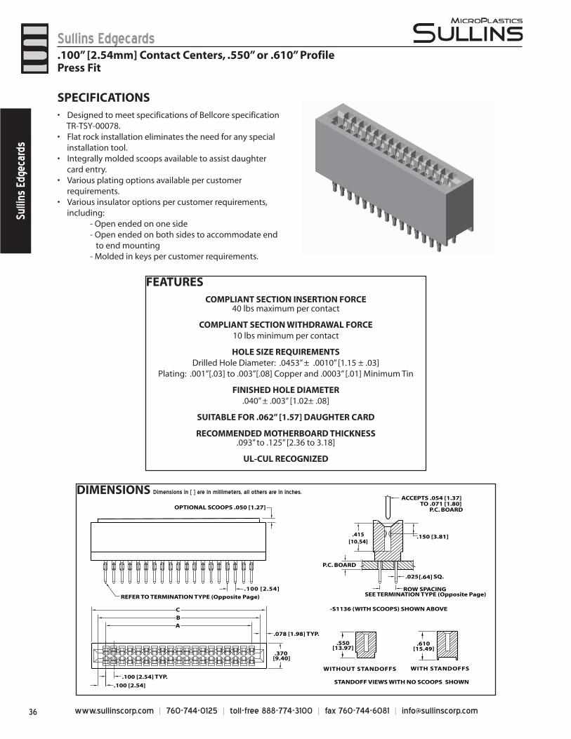
www.sullinscorp.com | 760-744-0125 | toll-free 888-774-3100 | fax 760-744-6081 | [email protected]
Sullins EdgecardsSu
llins
Edg
ecar
ds
DIMENSIONS Dimensions in [ ] are in millimeters, all others are in inches.
SPECIFICATIONSDesigned to• meet specifications of Bellcore specification
TR-TSY-00078.Flat rock installation eliminates the need for any special•
installation tool.Integrally molded scoops available to assist daughter •
card entry.Various plating options available per customer •
requirements.Various insulator options per customer requirements, •
including: - Open ended on one side - Open ended on both sides to accommodate end to end mounting - Molded in keys per customer requirements.
.100 [2.54]
.100 [2.54] TYP.
.370[9.40]
CBA
WITHOUT STANDOFFS WITH STANDOFFS
.078 [1.98] TYP.
REFER TO TERMINATION TYPE (Opposite Page)
.100 [2.54]
P.C. BOARD
.415[10.54]
.150 [3.81]
OPTIONAL SCOOPS .050 [1.27]
.550[13.97]
.610[15.49]
.025 SQ. [.64]
ACCEPTS .054 [1.37] TO .071 [1.80]
P.C. BOARD
ROW SPACING SEE TERMINATION TYPE (Opposite Page)
-S1136 (WITH SCOOPS) SHOWN ABOVE
STANDOFF VIEWS WITH NO SCOOPS SHOWN
FEATURESCOMPLIANT SECTION INSERTION FORCE
40 lbs maximum per contact
COMPLIANT SECTION WITHDRAWAL FORCE10 lbs minimum per contact
HOLE SIZE REQUIREMENTSDrilled Hole Diameter: .0453” ± .0010” [1.15 ± .03]
Plating: .001”[.03] to .003”[.08] Copper and .0003” [.01] Minimum Tin
FINISHED HOLE DIAMETER.040” ± .003” [1.02± .08]
SUITABLE FOR .062” [1.57] DAUGHTER CARD
RECOMMENDED MOTHERBOARD THICKNESS.093” to .125” [2.36 to 3.18]
UL-CUL RECOGNIZED
.100” [2.54mm] Contact Centers, .550” or .610” ProfilePress Fit
37www.sullinscorp.com | 760-744-0125 | toll-free 888-774-3100 | fax 760-744-6081 | [email protected]
Sullins EdgecardsSullins Edgecards
POSITIONS/CONTACTS
A±.008[0.20] B±.008[0.20] C±.015[0.38] POSITIONS/CONTACTS
A±.008[0.20] B±.008[0.20] C±.015[0.38]
INCH [MM] INCH [MM] INCH [MM] INCH [MM] INCH [MM] INCH [MM]
05/10 0.400 10.16 0.600 15.24 0.756 19.20 33/66 3.200 81.28 3.400 86.36 3.556 90.32
06/12 0.500 12.70 0.700 17.78 0.856 21.74 34/68 3.300 83.82 3.500 88.90 3.656 92.86
07/14 0.600 15.24 0.800 20.32 0.956 24.28 35/70 3.400 86.36 3.600 91.44 3.756 95.40
08/16 0.700 17.78 0.900 22.86 1.056 26.82 36/72 3.500 88.90 3.700 93.98 3.856 97.94
09/18 0.800 20.32 1.000 25.40 1.156 29.36 37/74 3.600 91.44 3.800 96.52 3.956 100.48
10/20 0.900 22.86 1.100 27.94 1.256 31.90 38/76 3.700 93.98 3.900 99.06 4.056 103.02
11/22 1.000 25.40 1.200 30.48 1.356 34.44 39/78 3.800 96.52 4.000 101.60 4.156 105.56
12/24 1.100 27.94 1.300 33.02 1.456 36.98 40/80 3.900 99.06 4.100 104.14 4.256 108.10
13/26 1.200 30.48 1.400 35.56 1.556 39.52 41/82 4.000 101.60 4.200 106.68 4.356 110.64
14/28 1.300 33.02 1.500 38.10 1.656 42.06 42/84 4.100 104.14 4.300 109.22 4.456 113.18
15/30 1.400 35.56 1.600 40.64 1.756 44.60 43/86 4.200 106.68 4.400 111.76 4.556 115.72
16/32 1.500 38.10 1.700 43.18 1.856 47.14 44/88 4.300 109.22 4.500 114.30 4.656 118.26
17/34 1.600 40.64 1.800 45.72 1.956 49.68 45/90 4.400 111.76 4.600 116.84 4.756 120.80
18/36 1.700 43.18 1.900 48.26 2.056 52.22 46/92 4.500 114.30 4.700 119.38 4.856 123.34
19/38 1.800 45.72 2.000 50.80 2.156 54.76 47/94 4.600 116.84 4.800 121.92 4.956 125.88
20/40 1.900 48.26 2.100 53.34 2.256 57.30 48/96 4.700 119.38 4.900 124.46 5.056 128.42
21/42 2.000 50.80 2.200 55.88 2.356 59.84 49/98 4.800 121.92 5.000 127.00 5.156 130.96
22/44 2.100 53.34 2.300 58.42 2.456 62.38 50/100 4.900 124.46 5.100 129.54 5.256 133.50
23/46 2.200 55.88 2.400 60.96 2.556 64.92 51/102 5.000 127.00 5.200 132.08 5.356 136.04
24/48 2.300 58.42 2.500 63.50 2.656 67.46 52/104 5.100 129.54 5.300 134.62 5.456 138.58
25/50 2.400 60.96 2.600 66.04 2.756 70.00 53/106 5.200 132.08 5.400 137.16 5.556 141.12
26/52 2.500 63.50 2.700 68.58 2.856 72.54 54/108 5.300 134.62 5.500 139.70 5.656 143.66
27/54 2.600 66.04 2.800 71.12 2.956 75.08 55/110 5.400 137.16 5.600 142.24 5.756 146.20
28/56 2.700 68.58 2.900 73.66 3.056 77.62 56/112 5.500 139.70 5.700 144.78 5.856 148.74
29/58 2.800 71.12 3.000 76.20 3.156 80.16 57/114 5.600 142.24 5.800 147.32 5.956 151.28
30/60 2.900 73.66 3.100 78.74 3.256 82.70 58/116 5.700 144.78 5.900 149.86 6.056 153.82
31/62 3.000 76.20 3.200 81.28 3.356 85.24 59/118 5.800 147.32 6.000 152.40 6.156 156.36
32/64 3.100 78.74 3.300 83.82 3.456 87.78 60/120 5.900 149.86 6.100 154.94 6.256 158.90
PART NUMBER CODING
.100” [2.54mm] Contact Centers, .550” or .610” ProfilePress Fit
E C C 43 D JB N - Sxxx
E = PBT/Phosphor Bronze
C = .100” [2.54mm]
MATERIALS (Insulator/Contact)
CONTACT CENTERS
NUMBER OF CONTACT POSITIONS
READOUT
TERMINATION TYPE
MOUNTING STYLE
MODIFICATIONS (Consult Factory)
D = DualH = Half Loaded
OMIT FOR STANDARD Special Number assigned for specials such as: - Scoops (-S1136) - Other Card Slot Depths - Slim Line Body (.315” [8.00mm])
Standoffs Row Spacing Tail LengthJB = No .200” [5.08mm] .190” [4.83mm]JC = No .200” [5.08mm] .625” [15.88mm]
JW = Yes .200” [5.08mm] .190” [4.83mm]JX = Yes .200” [5.08mm] .565” [14.35mm]JF = No .100” [2.54mm] .190” [4.83mm]JG = No .100” [2.54mm] .625” [15.88mm]JY = Yes .100” [2.54mm] .190” [4.83mm]JZ = Yes .100” [2.54mm] .565” [14.35mm]
N = No Mounting
B = Open Card Slot
All platings are Lead Free and have .000050” Nickel underplateContact Surface Termination
C = .000030” Gold .000100” Pure Tin, Matte
See Chart Below
CONTACT FINISH - RoHS Compliant
www.sullinscorp.com | 760-744-0125 | toll-free 888-774-3100 | fax 760-744-6081 | [email protected]
Sullins EdgecardsSu
llins
Edg
ecar
ds
SPECIFICATIONSAc• commodates .062” ± .008” [1.57 ± .20]
PC board (For .093” ±.008” [2.36 ± .20] PCB see page 40-41, 42-43; for .125” ±.008” [3.18 ± .20] PCB see page 40-41)
PBT, PPS or PA9T insulator• Molded-in key available• 3 amp current rating• per contact30 milli ohm maximum at rated current•
POLARIZING KEYREADOUT
DUAL (D) HALF LOADED (H)
EVENNUMBERSIDE
PLC-K1
KEY IN BETWEEN CONTACTS(ORDER SEPARATELY)
.038[0.97]
.100[2.54]
.285[7.24]
MOUNTING STYLE
.100” [2.54mm] Contact Centers, .610” Insulator HeightDip Solder/Wire Wrap/Right Angle/Card Extender
SIDE MOUNTING(S)
.245[6.22]
Ø.125[3.18] Ø.125 [3.18]
D = .250 [6.35] w = .430 [10.92]
FLUSH MOUNTING(D, W)
FLUSH MOUNTING WITHTHREADED INSERT(T, X)
#4-40
THREADEDINSERT(I)
#4-40
NO MOUNTINGEARS (N)
Ø.125[3.18]
.250[6.35]
CLEARANCEHOLE (H)
T = .250 [6.35]X = .430 [10.92]
TERMINATION TYPE
CANTILEVER TERMINATION TYPE
POST CROSS SECTION
K
POST LENGTHL
.025 [.64]
FITS MIN. HOLE SIZE
KS DIP SOLDER .025 [.64] SQUARE .190 [4.83] .040 [1.02]
KD DIP SOLDER .025 [.64] SQUARE .160 [4.06] .043 [1.09]
KM WIRE WRAP .025 [.64] SQUARE .560 [14.20] .040 [1.02]
*KA RIGHT ANGLE .025 [.64] SQUARE .100 [2.54] .043 [1.09]
*KE RIGHT ANGLE .025 [.64] SQUARE .180 [4.57] .043 [1.09]
*KU RIGHT ANGLE .025 [.64] SQUARE .250 [6.35] .043 [1.09]
*KJ RIGHT ANGLE .025 [.64] SQUARE .500 [12.70] .043 [1.09]
*KR CARD EXTENDER .025 [.64] SQUARE .235 [5.97] N/A
*KN CARD EXTENDER .025 [.64] SQUARE .605 [15.37] N/A
* KA, KE, KJ, KR, KN have no standoffs, unless requested.
HAIRPIN BELLOWS
TERMINATION TYPE
POST CROSS SECTION
K
POST LENGTHL
.025 [.64]
FITS MIN. HOLE SIZE
CW DIP SOLDER .015 x .025 [.38 x .64] .125 [3.18] .035 [0.76]
CT DIP SOLDER .015 x .025 [.38 x .64] .170 [4.32] .035 [0.76]
CS DIP SOLDER .025 [.64] SQUARE .160 [4.06] .040 [1.02]
CM WIRE WRAP .025 [.64] SQUARE .560 [ 14.20] .040 [1.02]
CA RIGHT ANGLE .025 [.64] SQUARE .100 [2.54] .043 [1.09]
CB RIGHT ANGLE .025 [.64] SQUARE .180 [4.57] .043 [1.09]
CC RIGHT ANGLE .025 [.64] SQUARE .250 [6.35] .043 [1.09]
LOOP BELLOWS
TERMINATION TYPE
POST CROSS SECTION
K
POST LENGTHL
.025 [.64]
FITS MIN. HOLE SIZE
TK,CK DIP SOLDER .026 [.66] ROUND .190 [4.83] .030 [0.76]
RS DIP SOLDER .025 [.64] SQUARE .190 [4.83] .040 [1.02]
RM WIRE WRAP .025 [.64] SQUARE .560 [14.20] .040 [1.02
TA RIGHT ANGLE .025 [.64] SQUARE .100 [2.54] .043 [1.09]
TB RIGHT ANGLE .025 [.64] SQUARE .180 [4.57] .043 [1.09]
TM RIGHT ANGLE .025 [.64] SQUARE .250 [6.35] .043 [1.09]
(CW, CT, CS, CM)
HAIRPIN BELLOWS
L
(TK, CK, RS, RM)
LOOP BELLOWS
K
(KS, KD, KM)
CANTILEVER
(CA, CB, CC, TA, TB, TM, KA, KE, KU, KJ)
NUMBERSIDE
L
.275[6.98]
.150[3.81]
RIGHT ANGLE
(CW, CT, CS, CM,TK, CK, RS,RM)Example P/N: EBC10DCSN-S288
(Requires -S288 Modification Code)
ACCOMMODATES.062 [1.57] PCB
HAIRPIN or LOOP CARD EXTENDER
(KR, KN)Example P/N: EBC10DKRN(Omit Modification Code)
ACCOMMODATES.062 [1.57] PCB
CANTILEVER CARD EXTENDER
L
.200[5.08]
K
.200[5.08]
L
.200[5.08]
K L K
KL
K
39www.sullinscorp.com | 760-744-0125 | toll-free 888-774-3100 | fax 760-744-6081 | [email protected]
Sullins EdgecardsSullins Edgecards
DIMENSIONS Dimensions in [ ] are in millimeters, all others are in inches.
1 3 5 7 9 131 133 135137 139
2 4 6 8 10 132 134 136 138 140
AB
C
DE F
REFER TO MOUNTING STYLE
REFER TOTERMINATION TYPE
.297 [7.54] INSERTION DEPTH
.180[4.57].250
[6.35]
.060[1.52] .100[2.54]
TYP.
.313[7.95]
.610[15.49]
.370 [9.40] CONTACT MARKINGS1 3 5 . . . 137 1392 4 6 . . . 138 140
Tolerances with PPS Insulator Material may vary slightly due to shrinkage differential; Consult Factory.
* Consult factory for availability.
.100” [2.54mm] Contact Centers, .610” Insulator HeightDip Solder/Wire Wrap/Right Angle/Card Extender
MATERIALS (Insulator/Contact)E = PBT/Phosphor Bronze (Standard)R = PPS/Phosphor BronzeG = PA9T/Phosphor BronzeH = PBT/Beryllium CopperA = PPS/Beryllium CopperJ = PA9T/Beryllium Copper
(Consult Factory for Other Materials)
CONTACT CENTERSC = .100” [2.54mm]
NUMBER OF CONTACT POSITIONS
READOUT (Opposite Page)D = DualH = Half Loaded
MOUNTING STYLE (Opposite Page)H = Clearance HolesI = Threaded InsertsS = Side MountingN = No Mounting
D, W = Flush MountingT, X = Flush Mounting With Threaded Inserts
TERMINATION TYPE (Opposite Page)Hairpin Bellows - Available with B or C plating and Phosphor Bronze Only
CS = .025” [.64mm] Square Dip SolderCM = .025 [.64mm] Square Wire Wrap
CA, CB, CC = .025” [.64mm] Square Right Angle CW, CT = .015” x .025” [.38 x .64] Dip Solder
Loop BellowsRS = .025” [0.64mm] Square Dip Solder
CK, TK = .026” [0.66mm] Round Dip SolderRM = .025” [0.64mm] Square Wire Wrap
TA, TB, TM = .025” [.64mm] Square Right AngleCantilever Bellows - Available in Y, B, or C plating Only
Not Available with R or A MaterialsKS, KD = .025” [.64mm] Square Dip Solder
KM = .025 [.64mm] Square Wire WrapKA, KE, KU, KJ = .025” [.64mm] Square Right Angle
KR, KN = .025” [.64mm] Square Card Extender
MODIFICATION CODE (Consult Factory)OMIT FORT STANDARD
-S189 = .200”[5.08mm] Row to Row on Right Angle-S288* = Card Extender Accepts .062”[1.57] PCB* Not Required on KR or KN Terminations
See Chart Below
E B C 70 D CM H - SxxxPART NUMBER CODING
POSITIONS/CONTACTS
INCHES [MILLIMETERS]A±.008 B±.008 C±.015 D±.010 E±.020 F±.015 A±0.20 B±0.20 C±0.38 D±0.25 E±0.51 F±0.38
06/12 0.500 0.700 0.860 1.175 1.435 0.750 12.70 17.78 21.84 29.85 36.45 19.0507/14* 0.600 0.800 0.960 1.275 1.535 0.850 15.24 20.32 24.38 32.39 38.99 21.5908/16 0.700 0.900 1.060 1.375 1.635 0.950 17.78 22.86 26.92 34.93 41.53 24.1310/20 0.900 1.100 1.260 1.575 1.835 1.150 22.86 27.94 32.00 40.01 46.61 29.2112/24 1.100 1.300 1.460 1.775 2.035 1.350 27.94 33.02 37.08 45.09 51.69 34.2913/26 1.200 1.400 1.560 1.875 2.135 1.450 30.48 35.56 39.62 47.63 54.23 36.8315/30 1.400 1.600 1.760 2.075 2.335 1.650 35.56 40.64 44.70 52.71 59.31 41.9117/34 1.600 1.800 1.960 2.275 2.535 1.850 40.64 45.72 49.78 57.79 64.39 46.9918/36 1.700 1.900 2.060 2.375 2.635 1.950 43.18 48.26 52.32 60.33 66.93 49.5320/40 1.900 2.100 2.260 2.575 2.835 2.150 48.26 53.34 57.40 65.41 72.01 54.6122/44 2.100 2.300 2.460 2.775 3.035 2.350 53.34 58.42 62.48 70.49 77.09 59.6924/48 2.300 2.500 2.660 2.975 3.235 2.550 58.42 63.50 67.56 75.57 82.17 64.7725/50 2.400 2.600 2.760 3.075 3.335 2.650 60.96 66.04 70.10 78.11 84.71 67.3128/56 2.700 2.900 3.060 3.375 3.635 2.950 68.58 73.66 77.72 85.73 92.33 74.9330/60 2.900 3.100 3.260 3.575 3.835 3.150 73.66 78.74 82.80 90.81 97.41 80.0131/62 3.000 3.200 3.360 3.675 3.935 3.250 76.20 81.28 85.34 93.35 99.95 82.5535/70 3.400 3.600 3.760 4.075 4.335 3.650 86.36 91.44 95.50 103.51 110.11 92.7136/72 3.500 3.700 3.860 4.175 4.435 3.750 88.90 93.98 98.04 106.05 112.65 95.2540/80 3.900 4.100 4.260 4.575 4.835 4.150 99.06 104.14 108.20 116.21 122.81 105.4143/86 4.200 4.400 4.560 4.875 5.135 4.450 106.68 111.76 115.82 123.83 130.43 113.0344/88 4.300 4.500 4.660 4.975 5.235 4.550 109.22 114.30 118.36 126.37 132.97 115.5749/98* 4.800 5.000 5.160 5.475 5.735 5.050 121.92 127.00 131.06 139.07 145.67 128.2750/100 4.900 5.100 5.260 5.575 5.835 5.150 124.46 129.54 133.60 141.61 148.21 130.8155/110 5.400 5.600 5.760 6.075 6.335 5.650 137.16 142.24 146.30 154.31 160.91 143.5160/120 5.900 6.100 6.260 6.575 6.835 6.150 149.86 154.94 159.00 167.01 173.61 156.2161/122 6.000 6.200 6.360 6.675 6.935 6.250 152.40 157.48 161.54 169.55 176.15 158.7565/130 6.400 6.600 6.760 7.075 7.335 6.650 162.56 167.64 171.70 179.71 186.31 168.9170/140 6.900 7.100 7.260 7.575 7.835 7.150 175.26 180.34 184.40 192.41 199.01 181.6180/160* 7.900 8.100 8.260 8.575 8.835 8.150 200.66 205.74 209.80 217.81 224.41 207.0190/180* 8.900 9.100 9.260 9.575 9.835 9.150 226.06 231.14 235.20 243.21 249.81 232.41100/200* 9.900 10.100 10.260 10.575 10.835 10.150 251.46 256.54 260.60 268.61 275.21 257.81
CONTACT FINISH - RoHS Compliant All platings are Lead Free and have .000050” Nickel underplate
Contact Surface TerminationB = .000010” Gold .000100” Pure Tin, MatteC = .000030” Gold .000100” Pure Tin, MatteG = .000010” Gold .000005” GoldY = .000030” Gold .000005” Gold
Contact Surface Overall PlatingS = .000010” Gold .000010” GoldM = .000030” Gold .000010” GoldE = .000100” Pure Tin, Matte .000100” Pure Tin, Matte
www.sullinscorp.com | 760-744-0125 | toll-free 888-774-3100 | fax 760-744-6081 | [email protected]
Sullins EdgecardsSu
llins
Edg
ecar
ds
TERMINATION TYPE
PCB LAYOUT
MOUNTING STYLE
READOUT
DUAL (D) HALF LOADED (H)
RIGHT ANGLEDIP SOLDER(TA, TB, TM)
LOOPBELLOWS(RS, RM)
.250[6.35]
L
K
L
.030±.015[0.75±0.38]
.150±.010[3.81±0.25]
K
RIGHT ANGLE(TA, TB, TM) TERMINATIONS
STRAIGHT PIN(RS, RM) TERMINATIONS
COMPONENT SIDE
.094[2.40]
.150[3.81].100 [2.54] CC
Ø.043[1.09]
Ø.125 [3.18], 2 PLS.
'Z' MOUNTING
.250[6.35]
AD
.100[2.54] CC
Ø.040[1.02]
Ø.125[3.18], 2 PLS. 'D'
or 'T' MOUNTING AD
Ø.125 [3.18]
.250 [6.35]
#4-40
.250 [6.35]
Ø.125 [3.18]
.250 [6.35]
NO MOUNTINGEARS (N)
FLUSH MOUNTING(D)
FLUSH MOUNTING WITHTHREADED INSERT
(T)
FLUSH MOUNTING WITH SIDE HOLES
(Z)
SPECIFICATIONSAcco• mmodates .093” ± .008” [2.36 ± .20] or
.125” ± .008” [3.18 ± .20] mating PC board (Consult factory for .031” ± .008” [.79 ± .20] boards)
PBT, PPS or PA9T insulator• Molded-in key available• 3 amp current rating• per contact30 milli ohm maximum at rated current•
TERMINATION TYPE
POST CROSS SECTION (K)
POST LENGTHL ±.025[.64]
FITS MIN. HOLE SIZE
RS Dip Solder .025[.64] SQUARE .190 [4.83] .040 [1.02]
RM Wire Wrap .025[.64] SQUARE .560 [14.20] .040 [1.02]
TA Right Angle .025[.64] SQUARE .100 [2.54] .043 [1.09]
TB Right Angle .025[.64] SQUARE .180 [4.57] .043 [1.09]
TM Right Angle .025[.64] SQUARE .250 [6.35] .043 [1.09]
.100” [2.54mm] Contact Centers, .610” Insulator Height, Dip Solder/Wire Wrap/Right Angle/Card Extender for .093”[2.36] or .125”[3.18] Mating PCB
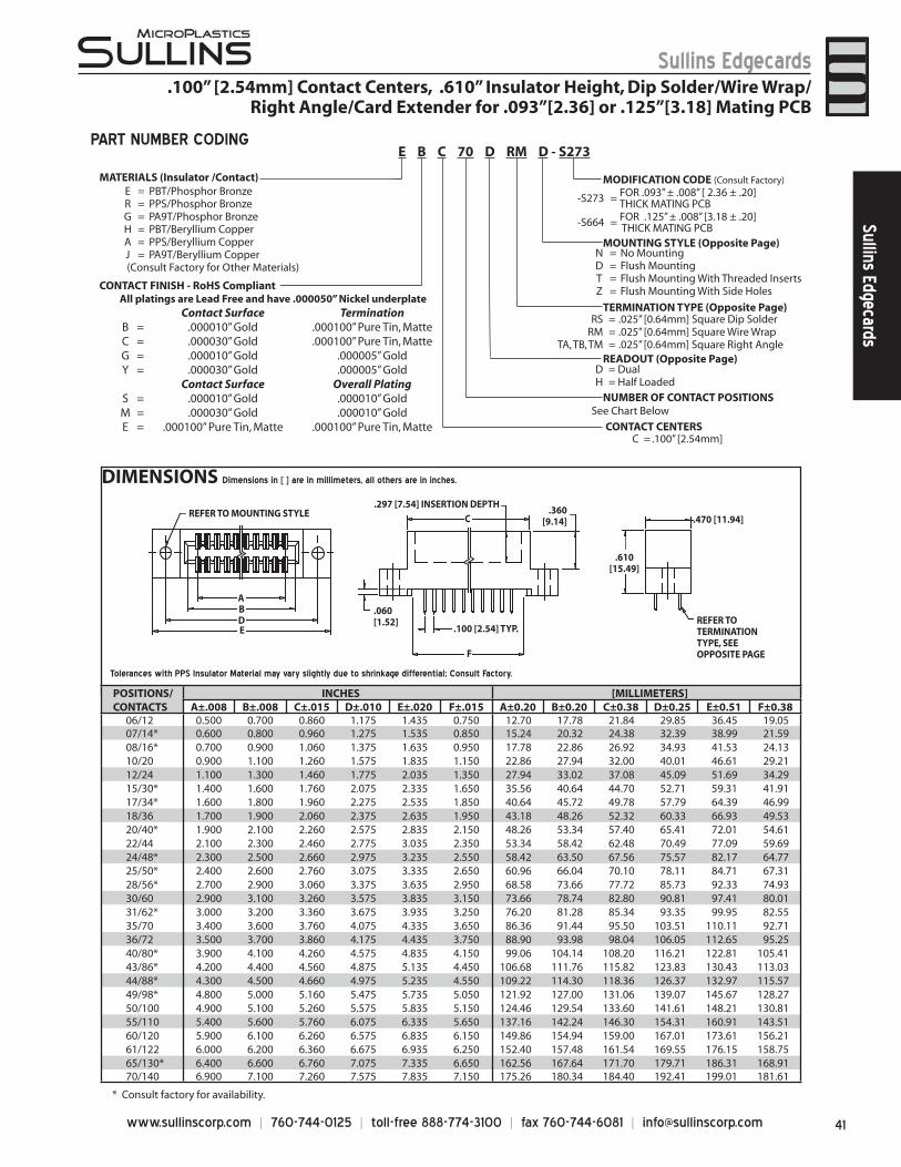
41www.sullinscorp.com | 760-744-0125 | toll-free 888-774-3100 | fax 760-744-6081 | [email protected]
Sullins EdgecardsSullins Edgecards
* Consult factory for availability.
DIMENSIONS Dimensions in [ ] are in millimeters, all others are in inches.
REFER TO MOUNTING STYLE.297 [7.54] INSERTION DEPTH
.360[9.14]
.060[1.52]
.100 [2.54] TYP.
AB
ED
F
.610[15.49]
.470 [11.94]
REFER TOTERMINATIONTYPE, SEEOPPOSITE PAGE
C
PART NUMBER CODING
MATERIALS (Insulator /Contact)
CONTACT FINISH - RoHS Compliant
CONTACT CENTERSC = .100” [2.54mm]
NUMBER OF CONTACT POSITIONS
D = DualH = Half Loaded
N = No MountingD = Flush MountingT = Flush Mounting With Threaded InsertsZ = Flush Mounting With Side Holes
RS = .025” [0.64mm] Square Dip SolderRM = .025” [0.64mm] Square Wire Wrap
TA, TB, TM = .025” [0.64mm] Square Right Angle
-S273 = FOR .093” ± .008” [ 2.36 ± .20]THICK MATING PCB
-S664 = FOR .125” ± .008” [3.18 ± .20] THICK MATING PCB
MODIFICATION CODE (Consult Factory)
READOUT (Opposite Page)
MOUNTING STYLE (Opposite Page)
TERMINATION TYPE (Opposite Page)
See Chart Below
E B C 70 D RM D - S273
.100” [2.54mm] Contact Centers, .610” Insulator Height, Dip Solder/Wire Wrap/Right Angle/Card Extender for .093”[2.36] or .125”[3.18] Mating PCB
Tolerances with PPS Insulator Material may vary slightly due to shrinkage differential; Consult Factory.
POSITIONS/CONTACTS
INCHES [MILLIMETERS]A±.008 B±.008 C±.015 D±.010 E±.020 F±.015 A±0.20 B±0.20 C±0.38 D±0.25 E±0.51 F±0.38
06/12 0.500 0.700 0.860 1.175 1.435 0.750 12.70 17.78 21.84 29.85 36.45 19.0507/14* 0.600 0.800 0.960 1.275 1.535 0.850 15.24 20.32 24.38 32.39 38.99 21.5908/16* 0.700 0.900 1.060 1.375 1.635 0.950 17.78 22.86 26.92 34.93 41.53 24.1310/20 0.900 1.100 1.260 1.575 1.835 1.150 22.86 27.94 32.00 40.01 46.61 29.2112/24 1.100 1.300 1.460 1.775 2.035 1.350 27.94 33.02 37.08 45.09 51.69 34.2915/30* 1.400 1.600 1.760 2.075 2.335 1.650 35.56 40.64 44.70 52.71 59.31 41.9117/34* 1.600 1.800 1.960 2.275 2.535 1.850 40.64 45.72 49.78 57.79 64.39 46.9918/36 1.700 1.900 2.060 2.375 2.635 1.950 43.18 48.26 52.32 60.33 66.93 49.5320/40* 1.900 2.100 2.260 2.575 2.835 2.150 48.26 53.34 57.40 65.41 72.01 54.6122/44 2.100 2.300 2.460 2.775 3.035 2.350 53.34 58.42 62.48 70.49 77.09 59.6924/48* 2.300 2.500 2.660 2.975 3.235 2.550 58.42 63.50 67.56 75.57 82.17 64.7725/50* 2.400 2.600 2.760 3.075 3.335 2.650 60.96 66.04 70.10 78.11 84.71 67.3128/56* 2.700 2.900 3.060 3.375 3.635 2.950 68.58 73.66 77.72 85.73 92.33 74.9330/60 2.900 3.100 3.260 3.575 3.835 3.150 73.66 78.74 82.80 90.81 97.41 80.0131/62* 3.000 3.200 3.360 3.675 3.935 3.250 76.20 81.28 85.34 93.35 99.95 82.5535/70 3.400 3.600 3.760 4.075 4.335 3.650 86.36 91.44 95.50 103.51 110.11 92.7136/72 3.500 3.700 3.860 4.175 4.435 3.750 88.90 93.98 98.04 106.05 112.65 95.2540/80* 3.900 4.100 4.260 4.575 4.835 4.150 99.06 104.14 108.20 116.21 122.81 105.4143/86* 4.200 4.400 4.560 4.875 5.135 4.450 106.68 111.76 115.82 123.83 130.43 113.0344/88* 4.300 4.500 4.660 4.975 5.235 4.550 109.22 114.30 118.36 126.37 132.97 115.5749/98* 4.800 5.000 5.160 5.475 5.735 5.050 121.92 127.00 131.06 139.07 145.67 128.2750/100 4.900 5.100 5.260 5.575 5.835 5.150 124.46 129.54 133.60 141.61 148.21 130.8155/110 5.400 5.600 5.760 6.075 6.335 5.650 137.16 142.24 146.30 154.31 160.91 143.5160/120 5.900 6.100 6.260 6.575 6.835 6.150 149.86 154.94 159.00 167.01 173.61 156.2161/122 6.000 6.200 6.360 6.675 6.935 6.250 152.40 157.48 161.54 169.55 176.15 158.7565/130* 6.400 6.600 6.760 7.075 7.335 6.650 162.56 167.64 171.70 179.71 186.31 168.9170/140 6.900 7.100 7.260 7.575 7.835 7.150 175.26 180.34 184.40 192.41 199.01 181.61
E = PBT/Phosphor BronzeR = PPS/Phosphor BronzeG = PA9T/Phosphor BronzeH = PBT/Beryllium CopperA = PPS/Beryllium CopperJ = PA9T/Beryllium Copper
(Consult Factory for Other Materials)
All platings are Lead Free and have .000050” Nickel underplate Contact Surface Termination
B = .000010” Gold .000100” Pure Tin, MatteC = .000030” Gold .000100” Pure Tin, MatteG = .000010” Gold .000005” GoldY = .000030” Gold .000005” Gold
Contact Surface Overall PlatingS = .000010” Gold .000010” GoldM = .000030” Gold .000010” GoldE = .000100” Pure Tin, Matte .000100” Pure Tin, Matte
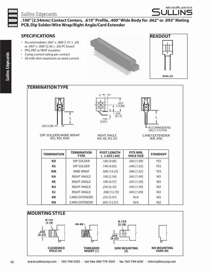
www.sullinscorp.com | 760-744-0125 | toll-free 888-774-3100 | fax 760-744-6081 | [email protected]
Sullins EdgecardsSu
llins
Edg
ecar
ds
MOUNTING STYLE
.100” [2.54mm] Contact Centers, .610” Profile, .400” Wide Body for .062” or .093” Mating PCB, Dip Solder/Wire Wrap/Right Angle/Card Extender
THREADEDINSERT (I)
#4-40
HOLE (H)
Ø.125 [3.18]
.250[6.35]
CLEARANCE SIDE MOUNTING(S)
[6.22].245
[3.18]Ø.125
NO MOUNTINGEARS (N)
SPECIFICATIONSAcco• mmodates .062” ± .008 [1.57 ± .20]
or .093” ± .008” [2.36 ± .20] PC boardPPS, PBT or PA9T insulator• 3 amp current rating• per contact30 milli ohm maximum at rated current•
READOUT
DUAL (D)
TERMINATION TYPE
.320[8.13]
.150[3.81]
L L
L
RIGHT ANGLE(KA, KE, KU, KJ)
DIP SOLDER/WIRE WRAP(KS, KD, KM)
CARD EXTENDER(KR, KN)
.625[15.88]
ACCOMMODATES.062 [1.57] PCB
.200 [5.08]
TERMINATION TERMINATION TYPE
POST LENGTH L ±.025 [.64]
FITS MIN. HOLE SIZE STANDOFF
KD DIP SOLDER .160 [4.06] .043 [1.09] YES
KS DIP SOLDER .190 [4.83] .040 [1.02] YES
KM WIRE WRAP .560 [14.22] .040 [1.02] YES
KA RIGHT ANGLE .100 [2.54] .043 [1.09] NO
KE RIGHT ANGLE .180 [4.57] .043 [1.09] NO
KU RIGHT ANGLE .250 [6.35] .043 [1.09] NO
KJ RIGHT ANGLE .500 [12.70] .043 [1.09] NO
KR CARD EXTENDER .235 [5.97] N/A NO
KN CARD EXTENDER .605 [15.37] N/A NO
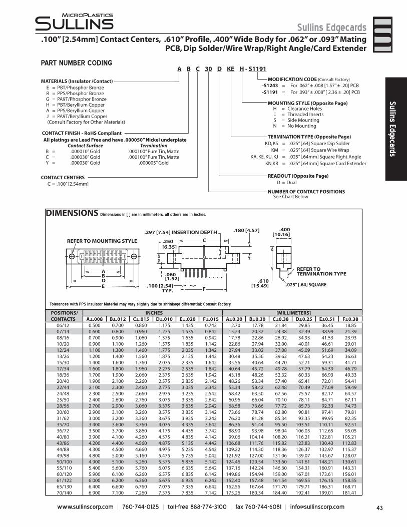
43www.sullinscorp.com | 760-744-0125 | toll-free 888-774-3100 | fax 760-744-6081 | [email protected]
Sullins EdgecardsSullins Edgecards
DIMENSIONS Dimensions in [ ] are in millimeters, all others are in inches.
AB
C
DE F
REFER TO MOUNTING STYLE
REFER TO TERMINATION TYPE
.297 [7.54] INSERTION DEPTH .180 [4.57]
.250[6.35]
.060[1.52]
.100 [2.54]TYP.
.610[15.49]
.400[10.16]
.025" [.64] SQUARE
CONTACT FINISH - RoHS Compliant
CONTACT CENTERSC = .100” [2.54mm]
NUMBER OF CONTACT POSITIONS
READOUT (Opposite Page)D = Dual
MOUNTING STYLE (Opposite Page)
TERMINATION TYPE (Opposite Page)KD, KS = .025” [.64] Square Dip Solder
KM = .025” [.64] Square Wire WrapKA, KE, KU, KJ = .025” [.64mm] Square Right Angle
KN,KR = .025” [.64mm] Square Card Extender
MODIFICATION CODE (Consult Factory)
H = Clearance HolesI = Threaded InsertsS = Side MountingN = No Mounting
E = PBT/Phosphor BronzeR = PPS/Phosphor BronzeG = PA9T/Phosphor BronzeH = PBT/Beryllium CopperA = PPS/Beryllium CopperJ = PA9T/Beryllium Copper
(Consult Factory for Other Materials)
-S1243 = For .062” ± .008 [1.57” ± .20] PCB-S1191 = For .093” ± .008” [ 2.36 ± .20] PCB
MATERIALS (Insulator /Contact)
See Chart Below
A B C 30 D KE H - S1191PART NUMBER CODING
Tolerances with PPS Insulator Material may vary slightly due to shrinkage differential; Consult Factory.
POSITIONS/CONTACTS
INCHES [MILLIMETERS]A±.008 B±.012 C±.015 D±.010 E±.020 F±.015 A±0.20 B±0.30 C±0.38 D±0.25 E±0.51 F±0.38
06/12 0.500 0.700 0.860 1.175 1.435 0.742 12.70 17.78 21.84 29.85 36.45 18.8507/14 0.600 0.800 0.960 1.275 1.535 0.842 15.24 20.32 24.38 32.39 38.99 21.3908/16 0.700 0.900 1.060 1.375 1.635 0.942 17.78 22.86 26.92 34.93 41.53 23.9310/20 0.900 1.100 1.260 1.575 1.835 1.142 22.86 27.94 32.00 40.01 46.61 29.0112/24 1.100 1.300 1.460 1.775 2.035 1.342 27.94 33.02 37.08 45.09 51.69 34.0913/26 1.200 1.400 1.560 1.875 2.135 1.442 30.48 35.56 39.62 47.63 54.23 36.6315/30 1.400 1.600 1.760 2.075 2.335 1.642 35.56 40.64 44.70 52.71 59.31 41.7117/34 1.600 1.800 1.960 2.275 2.535 1.842 40.64 45.72 49.78 57.79 64.39 46.7918/36 1.700 1.900 2.060 2.375 2.635 1.942 43.18 48.26 52.32 60.33 66.93 49.3320/40 1.900 2.100 2.260 2.575 2.835 2.142 48.26 53.34 57.40 65.41 72.01 54.4122/44 2.100 2.300 2.460 2.775 3.035 2.342 53.34 58.42 62.48 70.49 77.09 59.4924/48 2.300 2.500 2.660 2.975 3.235 2.542 58.42 63.50 67.56 75.57 82.17 64.5725/50 2.400 2.600 2.760 3.075 3.335 2.642 60.96 66.04 70.10 78.11 84.71 67.1128/56 2.700 2.900 3.060 3.375 3.635 2.942 68.58 73.66 77.72 85.73 92.33 74.7330/60 2.900 3.100 3.260 3.575 3.835 3.142 73.66 78.74 82.80 90.81 97.41 79.8131/62 3.000 3.200 3.360 3.675 3.935 3.242 76.20 81.28 85.34 93.35 99.95 82.3535/70 3.400 3.600 3.760 4.075 4.335 3.642 86.36 91.44 95.50 103.51 110.11 92.5136/72 3.500 3.700 3.860 4.175 4.435 3.742 88.90 93.98 98.04 106.05 112.65 95.0540/80 3.900 4.100 4.260 4.575 4.835 4.142 99.06 104.14 108.20 116.21 122.81 105.2143/86 4.200 4.400 4.560 4.875 5.135 4.442 106.68 111.76 115.82 123.83 130.43 112.8344/88 4.300 4.500 4.660 4.975 5.235 4.542 109.22 114.30 118.36 126.37 132.97 115.3749/98 4.800 5.000 5.160 5.475 5.735 5.042 121.92 127.00 131.06 139.07 145.67 128.0750/100 4.900 5.100 5.260 5.575 5.835 5.142 124.46 129.54 133.60 141.61 148.21 130.6155/110 5.400 5.600 5.760 6.075 6.335 5.642 137.16 142.24 146.30 154.31 160.91 143.3160/120 5.900 6.100 6.260 6.575 6.835 6.142 149.86 154.94 159.00 167.01 173.61 156.0161/122 6.000 6.200 6.360 6.675 6.935 6.242 152.40 157.48 161.54 169.55 176.15 158.5565/130 6.400 6.600 6.760 7.075 7.335 6.642 162.56 167.64 171.70 179.71 186.31 168.7170/140 6.900 7.100 7.260 7.575 7.835 7.142 175.26 180.34 184.40 192.41 199.01 181.41
All platings are Lead Free and have .000050” Nickel underplateContact Surface Termination
B = .000010” Gold .000100” Pure Tin, MatteC = .000030” Gold .000100” Pure Tin, MatteY = .000030” Gold .000005” Gold
.100” [2.54mm] Contact Centers, .610” Profile, .400” Wide Body for .062” or .093” Mating PCB, Dip Solder/Wire Wrap/Right Angle/Card Extender
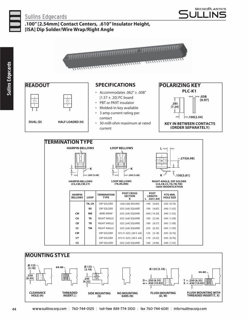
www.sullinscorp.com | 760-744-0125 | toll-free 888-774-3100 | fax 760-744-6081 | [email protected]
Sullins EdgecardsSu
llins
Edg
ecar
ds
TERMINATION TYPEHAIRPIN BELLOWS
LK
LOOP BELLOWS L
.275[6.98]
.150[3.81]
L
K
HAIRPIN BELLOWS(CS,CM,CW,CT)
LOOP BELLOWS(TK,RS,RM)
RIGHT ANGLE, DIP SOLDER(CA,CB,CC,TA,TB,TM)-S605 MODIFICATION
K
.200 [5.08] .200 [5.08]
MOUNTING STYLE
SIDE MOUNTING(S)
.245[6.22]
Ø.125[3.18] Ø.125 [3.18]
D = .250 [6.35] w = .430 [10.92]
FLUSH MOUNTING(D, W)
FLUSH MOUNTING WITHTHREADED INSERT(T, X)
#4-40
THREADEDINSERT(I)
#4-40
NO MOUNTINGEARS (N)
Ø.125[3.18]
.250[6.35]
CLEARANCEHOLE (H)
T = .250 [6.35]X = .430 [10.92]
HAIRPINBELLOWS LOOP
TERMINATION TYPE
POST CROSS SECTION
K
POST LENGTH
L .025 [.64]
FITS MIN.HOLE SIZE
TK, CK DIP SOLDER .026 [.66] ROUND .190 [4.83] .030 [0.76]
RS DIP SOLDER .025 [.64] SQUARE .190 [4.83] .040 [1.02]
CM RM WIRE WRAP .025 [.64] SQUARE .560 [ 14.20] .040 [1.02]
CA TA RIGHT ANGLE .025 [.64] SQUARE .100 [2.54] .043 [1.09]
CB TB RIGHT ANGLE .025 [.64] SQUARE .180 [4.57] .043 [1.09]
CC TM RIGHT ANGLE .025 [.64] SQUARE .250 [6.35] .043 [1.09]
CW DIP SOLDER .015 X .025 [.38 X .64] .125 [3.18] .035 [0.76]
CT DIP SOLDER .015 X .025 [.38 X .64] .170 [4.32] .035 [0.76]
CS DIP SOLDER .025 [.64] SQUARE .160 [4.06] .040 [1.02]
READOUT POLARIZING KEY
DUAL (D) HALF LOADED (H)
SPECIFICATIONSAccommodates• .062” ± .008”
[1.57 ± .20] PC board PBT or PA9T insulator• Molded-in key available• 3 amp current rating• per
contact30 milli ohm maximum at rated •
current
.100” [2.54mm] Contact Centers, .610” Insulator Height,[ISA] Dip Solder/Wire Wrap/Right Angle
PLC-K1
KEY IN BETWEEN CONTACTS(ORDER SEPARATELY)
.038[0.97]
.100[2.54]
.285[7.24]
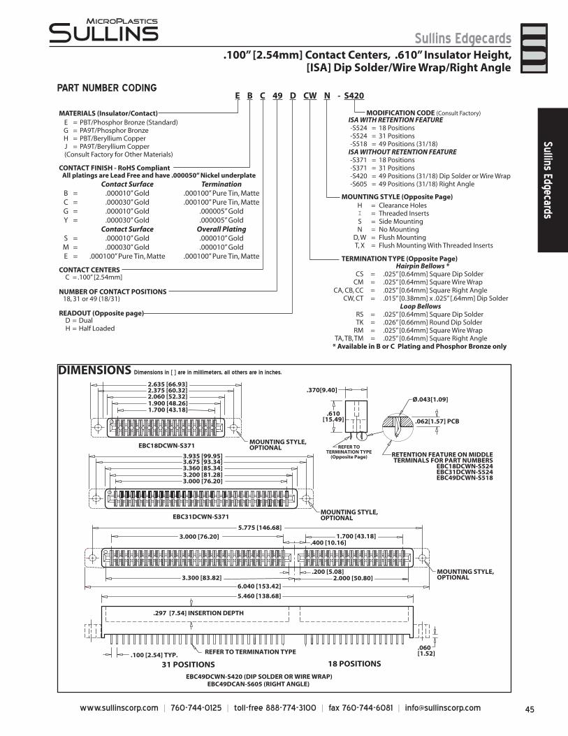
45www.sullinscorp.com | 760-744-0125 | toll-free 888-774-3100 | fax 760-744-6081 | [email protected]
Sullins EdgecardsSullins Edgecards
DIMENSIONS Dimensions in [ ] are in millimeters, all others are in inches.
.100 [2.54] TYP. REFER TO TERMINATION TYPE .060[1.52]
RETENTION FEATURE ON MIDDLETERMINALS FOR PART NUMBERS
EBC18DCWN-S524EBC31DCWN-S524EBC49DCWN-S518
EBC49DCWN-S420 (DIP SOLDER OR WIRE WRAP)EBC49DCAN-S605 (RIGHT ANGLE)
.062[1.57] PCB
.400 [10.16]
.200 [5.08]2.000 [50.80]
1.700 [43.18]3.000 [76.20]
3.300 [83.82]
5.460 [138.68]
6.040 [153.42]
5.775 [146.68]
.297 [7.54] INSERTION DEPTH
MOUNTING STYLE,OPTIONAL
.370[9.40]
.610[15.49]
MOUNTING STYLE,OPTIONAL
MOUNTING STYLE,OPTIONAL
3.000 [76.20]
1.700 [43.18]
3.360 [85.34]3.200 [81.28]
1.900 [48.26]
2.635 [66.93]
3.935 [99.95]
2.375 [60.32]
3.675 [93.34]
EBC31DCWN-S371
EBC18DCWN-S371
2.060 [52.32]
18 POSITIONS31 POSITIONS
REFER TOTERMINATION TYPE
(Opposite Page)
Ø.043[1.09]
PART NUMBER CODING
.100” [2.54mm] Contact Centers, .610” Insulator Height,[ISA] Dip Solder/Wire Wrap/Right Angle
MATERIALS (Insulator/Contact)
CONTACT CENTERSC = .100” [2.54mm]
NUMBER OF CONTACT POSITIONS18, 31 or 49 (18/31)
READOUT (Opposite page)D = DualH = Half Loaded
H = Clearance HolesI = Threaded InsertsS = Side MountingN = No Mounting
D, W = Flush MountingT, X = Flush Mounting With Threaded Inserts
Hairpin Bellows *CS = .025” [0.64mm] Square Dip Solder
CM = .025” [0.64mm] Square Wire WrapCA, CB, CC = .025” [0.64mm] Square Right Angle
CW, CT = .015” [0.38mm] x .025” [.64mm] Dip SolderLoop Bellows
RS = .025” [0.64mm] Square Dip SolderTK = .026” [0.66mm] Round Dip Solder
RM = .025” [0.64mm] Square Wire WrapTA, TB, TM = .025” [0.64mm] Square Right Angle
* Available in B or C Plating and Phosphor Bronze only
ISA WITH RETENTION FEATURE-S524 = 18 Positions-S524 = 31 Positions-S518 = 49 Positions (31/18)
ISA WITHOUT RETENTION FEATURE-S371 = 18 Positions-S371 = 31 Positions-S420 = 49 Positions (31/18) Dip Solder or Wire Wrap-S605 = 49 Positions (31/18) Right Angle
MODIFICATION CODE (Consult Factory)
MOUNTING STYLE (Opposite Page)
TERMINATION TYPE (Opposite Page)
E B C 49 D CW N - S420
E = PBT/Phosphor Bronze (Standard)G = PA9T/Phosphor BronzeH = PBT/Beryllium CopperJ = PA9T/Beryllium Copper
(Consult Factory for Other Materials)
CONTACT FINISH - RoHS CompliantAll platings are Lead Free and have .000050” Nickel underplate
Contact Surface TerminationB = .000010” Gold .000100” Pure Tin, MatteC = .000030” Gold .000100” Pure Tin, MatteG = .000010” Gold .000005” GoldY = .000030” Gold .000005” Gold
Contact Surface Overall PlatingS = .000010” Gold .000010” GoldM = .000030” Gold .000010” GoldE = .000100” Pure Tin, Matte .000100” Pure Tin, Matte
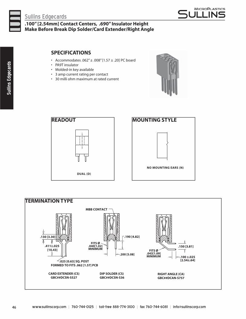
www.sullinscorp.com | 760-744-0125 | toll-free 888-774-3100 | fax 760-744-6081 | [email protected]
Sullins EdgecardsSu
llins
Edg
ecar
ds
TERMINATION TYPE
READOUT
DUAL (D)
NO MOUNTING EARS (N)
.100 ±.025 [2.54±.64]
.150 [3.81]
.025 [0.63] SQ. POST FORMED TO FITS .062 [1.57] PCB
.411±.025 [10.43]
.130 [3.30]
MBB CONTACT
CARD EXTENDER (CS)GBC##DCSN-S527
RIGHT ANGLE (CA)GBC##DCAN-S757
DIP SOLDER (CS)GBC##DCSN-S36
.190 [4.82]
FITS Ø.040[1.02]MINIMUM FITS Ø
.043[1.09]MINIMUM
.200 [5.08]
SPECIFICATIONSAccommodate• s .062” ± .008” [1.57 ± .20] PC boardPA9T insulator• Molded-in key available• 3 amp current rating• per contact30 milli ohm maximum at rated current•
.100” [2.54mm] Contact Centers, .690” Insulator HeightMake Before Break Dip Solder/Card Extender/Right Angle
MOUNTING STYLE
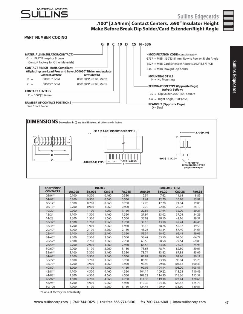
47www.sullinscorp.com | 760-744-0125 | toll-free 888-774-3100 | fax 760-744-6081 | [email protected]
Sullins EdgecardsSullins Edgecards
DIMENSIONS Dimensions in [ ] are in millimeters, all others are in inches.
.370 [9.40]
A
B
C
F .100 [2.54] TYP.
.515 [13.08] INSERTION DEPTH
.690 [17.52]
REFER TO TERMINATION TYPE
(Opposite Page)
.025 [.64] SQ.
POSITIONS/CONTACTS
INCHES [MILLIMETERS]A±.008 B±.008 C±.015 F±.015 A±0.20 B±0.20 C±0.38 F±0.38
02/04* 0.100 0.300 0.460 0.350 2.54 7.62 11.68 8.8904/08* 0.300 0.500 0.660 0.550 7.62 12.70 16.76 13.9706/12* 0.500 0.700 0.860 0.750 12.70 17.78 21.84 19.0508/16* 0.700 0.900 1.060 0.950 17.78 22.86 26.92 24.1310/20* 0.900 1.100 1.260 1.150 22.86 27.94 32.00 29.2112/24 1.100 1.300 1.460 1.350 27.94 33.02 37.08 34.2914/28 1.300 1.500 1.660 1.550 33.02 38.10 42.16 39.3716/32* 1.500 1.700 1.860 1.750 38.10 43.18 47.24 44.4518/36* 1.700 1.900 2.060 1.950 43.18 48.26 52.32 49.5320/40* 1.900 2.100 2.260 2.150 48.26 53.34 57.40 54.6122/44* 2.100 2.300 2.460 2.350 53.34 58.42 62.48 59.6924/48* 2.300 2.500 2.660 2.550 58.42 63.50 67.56 64.7726/52* 2.500 2.700 2.860 2.750 63.50 68.58 72.64 69.8528/56* 2.700 2.900 3.060 2.950 68.58 73.66 77.72 74.9330/60* 2.900 3.100 3.260 3.150 73.66 78.74 82.80 80.0132/64* 3.100 3.300 3.460 3.350 78.74 83.82 87.88 85.0934/68* 3.300 3.500 3.660 3.550 83.82 88.90 92.96 90.1736/72* 3.500 3.700 3.860 3.750 88.90 93.98 98.04 95.2538/76* 3.700 3.900 4.060 3.950 93.98 99.06 103.12 100.3340/80* 3.900 4.100 4.260 4.150 99.06 104.14 108.20 105.4142/84* 4.100 4.300 4.460 4.350 104.14 109.22 113.28 110.4944/88* 4.300 4.500 4.660 4.550 109.22 114.30 118.36 115.5746/92* 4.500 4.700 4.860 4.750 114.30 119.38 123.44 120.6548/96* 4.700 4.900 5.060 4.950 119.38 124.46 128.52 125.7350/100 4.900 5.100 5.260 5.150 124.46 129.54 133.60 130.81
* Consult factory for availability.
MATERIALS (INSULATOR/CONTACT)G = PA9T/Phosphor Bronze (Consult Factory for Other Materials)
CONTACT FINISH - RoHS Compliant
CONTACT CENTERSC = .100” [2.54mm]
NUMBER OF CONTACT POSITIONS
D = Dual
MOUNTING STYLEN = No Mounting
Hairpin Bellows
CS = Dip Solder .025” [.64] Square
CA = Right Angle, .100” [2.54]
-S757 = MBB, .150”[3.81mm] Row to Row on Right Angle
-S527 = MBB, Card Extender Accepts .062”[1.57] PCB
-S36 = MBB, Straight Dip-Solder
MODIFICATION CODE (Consult Factory)
READOUT (Opposite Page)
TERMINATION TYPE (Opposite Page)
See Chart Below
G B C 10 D CS N - S36
PART NUMBER CODING
.100” [2.54mm] Contact Centers, .690” Insulator HeightMake Before Break Dip Solder/Card Extender/Right Angle
All platings are Lead Free and have .000050” Nickel underplateContact Surface Termination
B = .000010” Gold .000100” Pure Tin, Matte
C = .000030” Gold .000100” Pure Tin, Matte
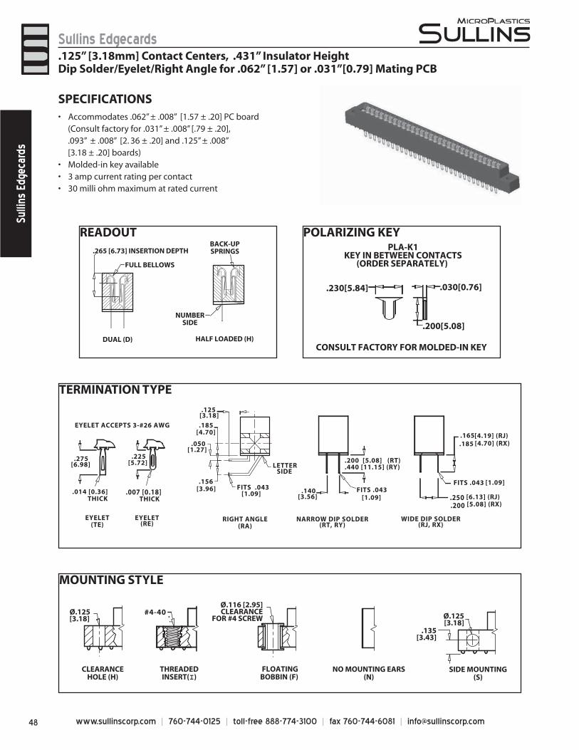
www.sullinscorp.com | 760-744-0125 | toll-free 888-774-3100 | fax 760-744-6081 | [email protected]
Sullins EdgecardsSu
llins
Edg
ecar
ds
SPECIFICATIONSAccommodat• es .062” ± .008” [1.57 ± .20] PC board
(Consult factory for .031” ± .008” [.79 ± .20], .093” ± .008” [2. 36 ± .20] and .125” ± .008” [3.18 ± .20] boards)
Molded-in key available• 3 amp current rating• per contact30 milli ohm maximum at rated current•
TERMINATION TYPE
EYELET ACCEPTS 3-#26 AWG
[5.72].225
.014 [0.36]THICK
EYELET(TE)
EYELET(RE)
[6.98].275
.007 [0.18] THICK
LETTER SIDE
[4.70].185
[3.96].156
[3.18].125
[1.27].050
RIGHT ANGLE(RA)
FITS .043 [1.09] [6.13] (RJ).250
[4.70] (RX).185
NARROW DIP SOLDER(RT, RY)
WIDE DIP SOLDER(RJ, RX)
[3.56].140
.200 [5.08] (RT)
.440 [11.15] (RY)
FITS .043 [1.09]
FITS .043 [1.09]
[5.08] (RX).200
[4.19] (RJ).165
MOUNTING STYLE
Ø.125[3.18]
CLEARANCEHOLE (H)
THREADEDINSERT(I)
FLOATINGBOBBIN (F)
NO MOUNTING EARS(N)
SIDE MOUNTING(S)
#4-40Ø.116 [2.95]CLEARANCE
FOR #4 SCREW
.135[3.43]
Ø.125[3.18]
POLARIZING KEY
NUMBERSIDE
.265 [6.73] INSERTION DEPTH
DUAL (D)
FULL BELLOWS
HALF LOADED (H)
BACK-UPSPRINGS
READOUT
.125” [3.18mm] Contact Centers, .431” Insulator HeightDip Solder/Eyelet/Right Angle for .062” [1.57] or .031”[0.79] Mating PCB
.230[5.84] .030[0.76]
.200[5.08]
CONSULT FACTORY FOR MOLDED-IN KEY
PLA-K1KEY IN BETWEEN CONTACTS
(ORDER SEPARATELY)
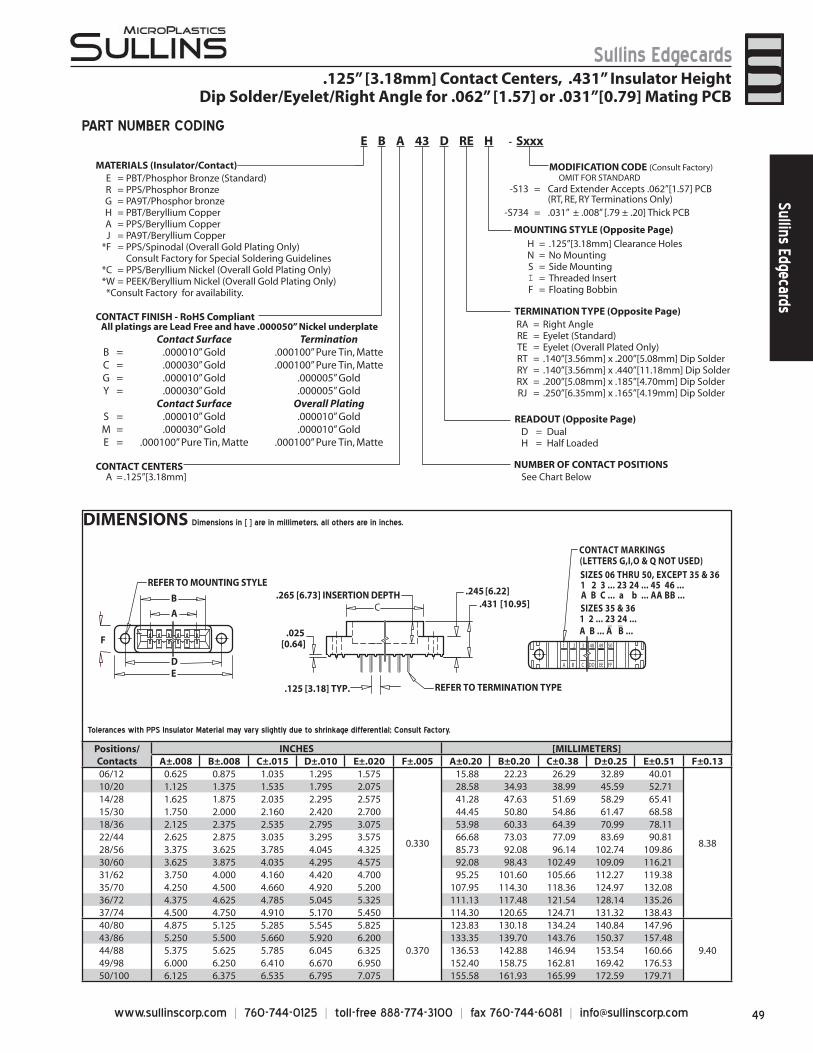
49www.sullinscorp.com | 760-744-0125 | toll-free 888-774-3100 | fax 760-744-6081 | [email protected]
Sullins EdgecardsSullins Edgecards
DIMENSIONS Dimensions in [ ] are in millimeters, all others are in inches.
MATERIALS (Insulator/Contact)E = PBT/Phosphor Bronze (Standard)R = PPS/Phosphor BronzeG = PA9T/Phosphor bronzeH = PBT/Beryllium CopperA = PPS/Beryllium CopperJ = PA9T/Beryllium Copper
*F = PPS/Spinodal (Overall Gold Plating Only)Consult Factory for Special Soldering Guidelines
*C = PPS/Beryllium Nickel (Overall Gold Plating Only)*W = PEEK/Beryllium Nickel (Overall Gold Plating Only) *Consult Factory for availability.
CONTACT FINISH - RoHS Compliant
CONTACT CENTERSA = .125”[3.18mm]
NUMBER OF CONTACT POSITIONS
D = DualH = Half Loaded
H = .125”[3.18mm] Clearance HolesN = No MountingS = Side MountingI = Threaded InsertF = Floating Bobbin
RA = Right AngleRE = Eyelet (Standard)TE = Eyelet (Overall Plated Only)RT = .140”[3.56mm] x .200”[5.08mm] Dip SolderRY = .140”[3.56mm] x .440”[11.18mm] Dip SolderRX = .200”[5.08mm] x .185”[4.70mm] Dip SolderRJ = .250”[6.35mm] x .165”[4.19mm] Dip Solder
A B ... A B ...
CONTACT MARKINGS(LETTERS G,I,O & Q NOT USED)SIZES 06 THRU 50, EXCEPT 35 & 361 2 3 ... 23 24 ... 45 46 ...A B C ... a b ... AA BB ...SIZES 35 & 361 2 ... 23 24 ... _ _
AC
D
B
E
F
REFER TO MOUNTING STYLE
1 2 3 48 49 50
A B C DD EE FF
REFER TO TERMINATION TYPE.125 [3.18] TYP.
.265 [6.73] INSERTION DEPTH[10.95].431
[6.22].245
[0.64].025
MODIFICATION CODE (Consult Factory) OMIT FOR STANDARD
READOUT (Opposite Page)
MOUNTING STYLE (Opposite Page)
TERMINATION TYPE (Opposite Page)
-S13 = Card Extender Accepts .062”[1.57] PCB(RT, RE, RY Terminations Only)
-S734 = .031” ± .008” [.79 ± .20] Thick PCB
See Chart Below
PART NUMBER CODING
.125” [3.18mm] Contact Centers, .431” Insulator HeightDip Solder/Eyelet/Right Angle for .062” [1.57] or .031”[0.79] Mating PCB
Tolerances with PPS Insulator Material may vary slightly due to shrinkage differential; Consult Factory.
E B A 43 D RE H - Sxxx
Positions/Contacts
INCHES [MILLIMETERS]A±.008 B±.008 C±.015 D±.010 E±.020 F±.005 A±0.20 B±0.20 C±0.38 D±0.25 E±0.51 F±0.13
06/12 0.625 0.875 1.035 1.295 1.575
0.330
15.88 22.23 26.29 32.89 40.01
8.38
10/20 1.125 1.375 1.535 1.795 2.075 28.58 34.93 38.99 45.59 52.7114/28 1.625 1.875 2.035 2.295 2.575 41.28 47.63 51.69 58.29 65.4115/30 1.750 2.000 2.160 2.420 2.700 44.45 50.80 54.86 61.47 68.5818/36 2.125 2.375 2.535 2.795 3.075 53.98 60.33 64.39 70.99 78.1122/44 2.625 2.875 3.035 3.295 3.575 66.68 73.03 77.09 83.69 90.8128/56 3.375 3.625 3.785 4.045 4.325 85.73 92.08 96.14 102.74 109.8630/60 3.625 3.875 4.035 4.295 4.575 92.08 98.43 102.49 109.09 116.2131/62 3.750 4.000 4.160 4.420 4.700 95.25 101.60 105.66 112.27 119.3835/70 4.250 4.500 4.660 4.920 5.200 107.95 114.30 118.36 124.97 132.0836/72 4.375 4.625 4.785 5.045 5.325 111.13 117.48 121.54 128.14 135.2637/74 4.500 4.750 4.910 5.170 5.450 114.30 120.65 124.71 131.32 138.4340/80 4.875 5.125 5.285 5.545 5.825
0.370
123.83 130.18 134.24 140.84 147.96
9.4043/86 5.250 5.500 5.660 5.920 6.200 133.35 139.70 143.76 150.37 157.4844/88 5.375 5.625 5.785 6.045 6.325 136.53 142.88 146.94 153.54 160.6649/98 6.000 6.250 6.410 6.670 6.950 152.40 158.75 162.81 169.42 176.5350/100 6.125 6.375 6.535 6.795 7.075 155.58 161.93 165.99 172.59 179.71
All platings are Lead Free and have .000050” Nickel underplate Contact Surface Termination
B = .000010” Gold .000100” Pure Tin, MatteC = .000030” Gold .000100” Pure Tin, MatteG = .000010” Gold .000005” GoldY = .000030” Gold .000005” Gold
Contact Surface Overall PlatingS = .000010” Gold .000010” GoldM = .000030” Gold .000010” GoldE = .000100” Pure Tin, Matte .000100” Pure Tin, Matte
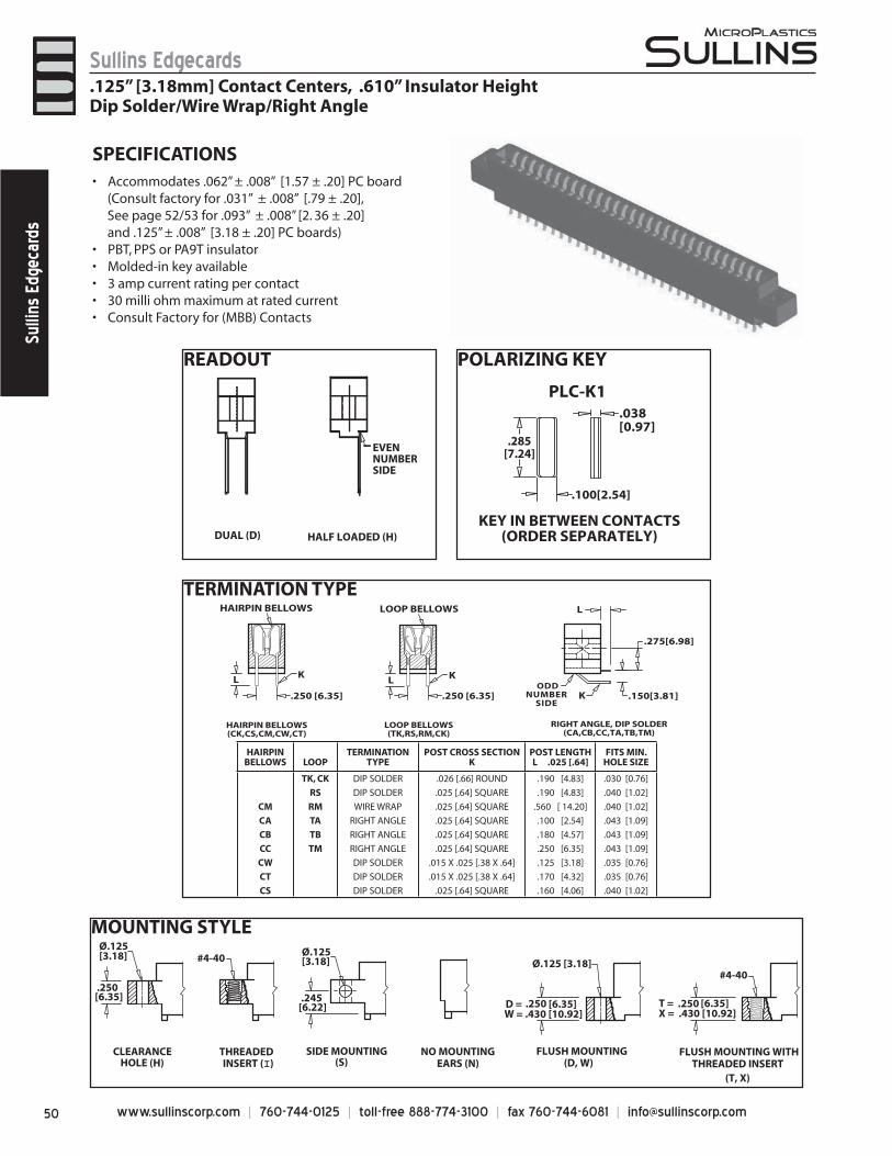
www.sullinscorp.com | 760-744-0125 | toll-free 888-774-3100 | fax 760-744-6081 | [email protected]
Sullins EdgecardsSu
llins
Edg
ecar
ds
SPECIFICATIONSAccom• modates .062” ± .008” [1.57 ± .20] PC board
(Consult factory for .031” ± .008” [.79 ± .20], See page 52/53 for .093” ± .008” [2. 36 ± .20] and .125” ± .008” [3.18 ± .20] PC boards)
PBT, PPS or PA9T insulator• Molded-in key available• 3 amp current rating• per contact30 milli ohm maximum at rated current• Consult Factory for (MBB) Contacts •
MOUNTING STYLE
T =
SIDE MOUNTING (S)
[6.22].245
[3.18]Ø.125
Ø.125 [3.18]
[6.35]D = .250
FLUSH MOUNTING (D, W)
W = .430 [10.92]
FLUSH MOUNTING WITH THREADED INSERT
(T, X)
#4-40
[6.35].250 X = .430 [10.92]
THREADEDINSERT (I)
#4-40
NO MOUNTINGEARS (N) HOLE (H)
[3.18]Ø.125
[6.35].250
CLEARANCE
TERMINATION TYPE
ODDNUMBER
SIDE
HAIRPIN BELLOWS
L K
LOOP BELLOWS L
.275[6.98]
.150[3.81]
L
K
HAIRPIN BELLOWS(CK,CS,CM,CW,CT)
LOOP BELLOWS(TK,RS,RM,CK)
RIGHT ANGLE, DIP SOLDER(CA,CB,CC,TA,TB,TM)
.250 [6.35] .250 [6.35]
K
HAIRPINBELLOWS LOOP
TERMINATION TYPE
POST CROSS SECTIONK
POST LENGTH L .025 [.64]
FITS MIN.HOLE SIZE
TK, CK DIP SOLDER .026 [.66] ROUND .190 [4.83] .030 [0.76]
RS DIP SOLDER .025 [.64] SQUARE .190 [4.83] .040 [1.02]
CM RM WIRE WRAP .025 [.64] SQUARE .560 [ 14.20] .040 [1.02]
CA TA RIGHT ANGLE .025 [.64] SQUARE .100 [2.54] .043 [1.09]
CB TB RIGHT ANGLE .025 [.64] SQUARE .180 [4.57] .043 [1.09]
CC TM RIGHT ANGLE .025 [.64] SQUARE .250 [6.35] .043 [1.09]
CW DIP SOLDER .015 X .025 [.38 X .64] .125 [3.18] .035 [0.76]
CT DIP SOLDER .015 X .025 [.38 X .64] .170 [4.32] .035 [0.76]
CS DIP SOLDER .025 [.64] SQUARE .160 [4.06] .040 [1.02]
.125” [3.18mm] Contact Centers, .610” Insulator HeightDip Solder/Wire Wrap/Right Angle
READOUT
DUAL (D) HALF LOADED (H)
EVENNUMBERSIDE
POLARIZING KEY
PLC-K1
KEY IN BETWEEN CONTACTS(ORDER SEPARATELY)
.038[0.97]
.100[2.54]
.285[7.24]
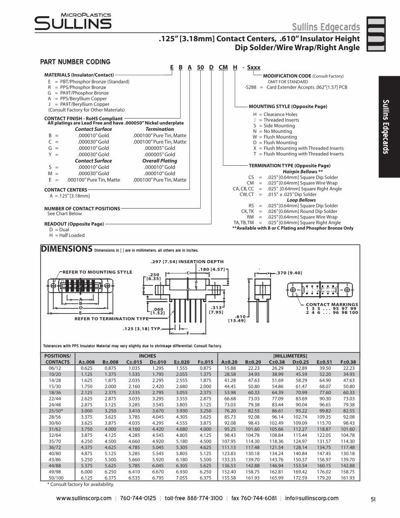
51www.sullinscorp.com | 760-744-0125 | toll-free 888-774-3100 | fax 760-744-6081 | [email protected]
Sullins EdgecardsSullins Edgecards
.125” [3.18mm] Contact Centers, .610” Insulator HeightDip Solder/Wire Wrap/Right Angle
DIMENSIONS Dimensions in [ ] are in millimeters, all others are in inches.
1 3 5 95 97 992 4 6 96 98 100
.370 [9.40]
AB
C
DE
F.125 [3.18] TYP.
[1.52].060
[6.35].250
.610[15.49]
.180 [4.57]
[7.95].313
.297 [7.54] INSERTION DEPTH
REFER TO MOUNTING STYLE
REFER TO TERMINATION TYPE
CONTACT MARKINGS1 3 5 . . . 95 97 992 4 6 . . . 96 98 100
* Consult factory for availability.
PART NUMBER CODING
MATERIALS (Insulator/Contact)E = PBT/Phosphor Bronze (Standard)R = PPS/Phosphor BronzeG = PA9T/Phosphor BronzeA = PPS/Beryllium CopperJ = PA9T/Beryllium Copper
(Consult Factory for Other Materials)
CONTACT FINISH - RoHS Compliant
CONTACT CENTERSA = .125” [3.18mm]
NUMBER OF CONTACT POSITIONS
READOUT (Opposite Page)D = DualH = Half Loaded
MOUNTING STYLE (Opposite Page)
H = Clearance HolesI = Threaded InsertsS = Side MountingN = No MountingW = Flush MountingD = Flush MountingX = Flush Mounting with Threaded InsertsT = Flush Mounting with Threaded Inserts
TERMINATION TYPE (Opposite Page)Hairpin Bellows **
CS = .025” [0.64mm] Square Dip SolderCM = .025” [0.64mm] Square Wire Wrap
CA, CB, CC = .025” [0.64mm] Square Right AngleCW, CT = .015” x .025” Dip Solder
Loop BellowsRS = .025” [0.64mm] Square Dip Solder
CK, TK = .026” [0.66mm] Round Dip Solder RM = .025” [0.64mm] Square Wire Wrap
TA, TB, TM = .025” [0.64mm] Square Right Angle**Available with B or C Plating and Phosphor Bronze Only
MODIFICATION CODE (Consult Factory) OMIT FOR STANDARD
-S288 = Card Extender Accepts .062”[1.57] PCB
See Chart Below
E B A 50 D CM H - Sxxx
All platings are Lead Free and have .000050” Nickel underplate Contact Surface Termination
B = .000010” Gold .000100” Pure Tin, MatteC = .000030” Gold .000100” Pure Tin, MatteG = .000010” Gold .000005” GoldY = .000030” Gold .000005” Gold
Contact Surface Overall PlatingS = .000010” Gold .000010” GoldM = .000030” Gold .000010” GoldE = .000100” Pure Tin, Matte .000100” Pure Tin, Matte
Tolerances with PPS Insulator Material may vary slightly due to shrinkage differential; Consult Factory.
POSITIONS/CONTACTS
INCHES [MILLIMETERS]A±.008 B±.008 C±.015 D±.010 E±.020 F±.015 A±0.20 B±0.20 C±0.38 D±0.25 E±0.51 F±0.38
06/12 0.625 0.875 1.035 1.295 1.555 0.875 15.88 22.23 26.29 32.89 39.50 22.2310/20 1.125 1.375 1.535 1.795 2.055 1.375 28.58 34.93 38.99 45.59 52.20 34.9314/28 1.625 1.875 2.035 2.295 2.555 1.875 41.28 47.63 51.69 58.29 64.90 47.6315/30 1.750 2.000 2.160 2.420 2.680 2.000 44.45 50.80 54.86 61.47 68.07 50.8018/36 2.125 2.375 2.535 2.795 3.055 2.375 53.98 60.33 64.39 70.99 77.60 60.3322/44 2.625 2.875 3.035 3.295 3.555 2.875 66.68 73.03 77.09 83.69 90.30 73.0324/48 2.875 3.125 3.285 3.545 3.805 3.125 73.03 79.38 83.44 90.04 96.65 79.3825/50* 3.000 3.250 3.410 3.670 3.930 3.250 76.20 82.55 86.61 93.22 99.82 82.5528/56 3.375 3.625 3.785 4.045 4.305 3.625 85.73 92.08 96.14 102.74 109.35 92.0830/60 3.625 3.875 4.035 4.295 4.555 3.875 92.08 98.43 102.49 109.09 115.70 98.4331/62 3.750 4.000 4.160 4.420 4.680 4.000 95.25 101.60 105.66 112.27 118.87 101.6032/64 3.875 4.125 4.285 4.545 4.805 4.125 98.43 104.78 108.84 115.44 122.05 104.7835/70 4.250 4.500 4.660 4.920 5.180 4.500 107.95 114.30 118.36 124.97 131.57 114.3036/72 4.375 4.625 4.785 5.045 5.305 4.625 111.13 117.48 121.54 128.14 134.75 117.4840/80 4.875 5.125 5.285 5.545 5.805 5.125 123.83 130.18 134.24 140.84 147.45 130.1843/86 5.250 5.500 5.660 5.920 6.180 5.500 133.35 139.70 143.76 150.37 156.97 139.7044/88 5.375 5.625 5.785 6.045 6.305 5.625 136.53 142.88 146.94 153.54 160.15 142.8849/98 6.000 6.250 6.410 6.670 6.930 6.250 152.40 158.75 162.81 169.42 176.02 158.7550/100 6.125 6.375 6.535 6.795 7.055 6.375 155.58 161.93 165.99 172.59 179.20 161.93
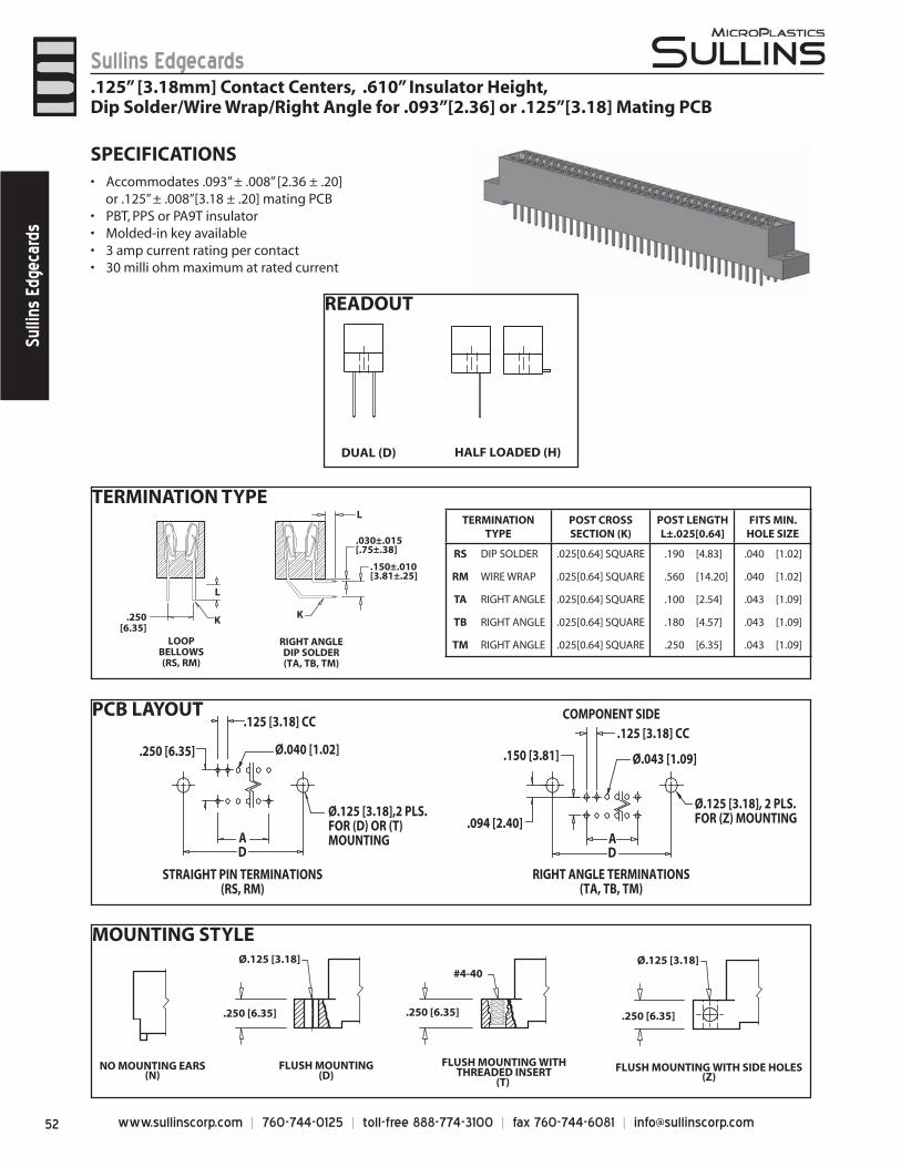
www.sullinscorp.com | 760-744-0125 | toll-free 888-774-3100 | fax 760-744-6081 | [email protected]
Sullins EdgecardsSu
llins
Edg
ecar
ds
PCB LAYOUT
RIGHT ANGLE TERMINATIONS(TA, TB, TM)
STRAIGHT PIN TERMINATIONS(RS, RM)
COMPONENT SIDE
.150 [3.81]
.094 [2.40]
.125 [3.18] CC
Ø.043 [1.09]
Ø.125 [3.18], 2 PLS.FOR (Z) MOUNTING
.250 [6.35]
.125 [3.18] CC
Ø.040 [1.02]
AD
AD
Ø.125 [3.18],2 PLS. FOR (D) OR (T) MOUNTING
MOUNTING STYLEØ.125 [3.18]
.250 [6.35]
FLUSH MOUNTING(D)
FLUSH MOUNTING WITHTHREADED INSERT
(T)
#4-40
.250 [6.35]
NO MOUNTING EARS(N)
Ø.125 [3.18]
.250 [6.35]
FLUSH MOUNTING WITH SIDE HOLES(Z)
SPECIFICATIONSAccommodate• s .093” ± .008” [2.36 ± .20]
or .125” ± .008”[3.18 ± .20] mating PCBPBT, PPS or PA9T insulator• Molded-in key available• 3 amp current rating• per contact30 milli ohm maximum at rated current •
READOUT
DUAL (D) HALF LOADED (H)
.125” [3.18mm] Contact Centers, .610” Insulator Height, Dip Solder/Wire Wrap/Right Angle for .093”[2.36] or .125”[3.18] Mating PCB
TERMINATION TYPE
RIGHT ANGLEDIP SOLDER(TA, TB, TM)
LOOPBELLOWS(RS, RM)
.250[6.35]
L
K
.030±.015[.75±.38]
.150±.010[3.81±.25]
L
K
TERMINATION TYPE
POST CROSS SECTION (K)
POST LENGTH L±.025[0.64]
FITS MIN. HOLE SIZE
RS DIP SOLDER .025[0.64] SQUARE .190 [4.83] .040 [1.02]
RM WIRE WRAP .025[0.64] SQUARE .560 [14.20] .040 [1.02]
TA RIGHT ANGLE .025[0.64] SQUARE .100 [2.54] .043 [1.09]
TB RIGHT ANGLE .025[0.64] SQUARE .180 [4.57] .043 [1.09]
TM RIGHT ANGLE .025[0.64] SQUARE .250 [6.35] .043 [1.09]
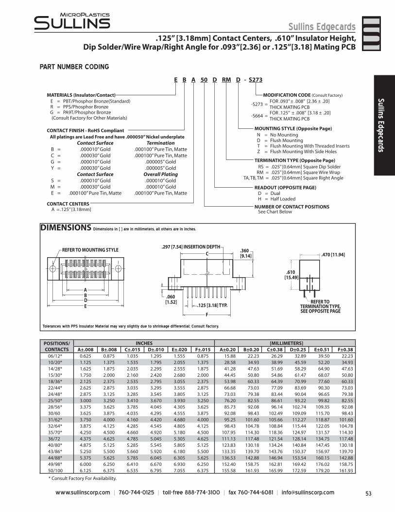
53www.sullinscorp.com | 760-744-0125 | toll-free 888-774-3100 | fax 760-744-6081 | [email protected]
Sullins EdgecardsSullins Edgecards
POSITIONS/CONTACTS
INCHES [MILLIMETERS]A±.008 B±.008 C±.015 D±.010 E±.020 F±.015 A±0.20 B±0.20 C±0.38 D±0.25 E±0.51 F±0.38
06/12* 0.625 0.875 1.035 1.295 1.555 0.875 15.88 22.23 26.29 32.89 39.50 22.2310/20* 1.125 1.375 1.535 1.795 2.055 1.375 28.58 34.93 38.99 45.59 52.20 34.9314/28* 1.625 1.875 2.035 2.295 2.555 1.875 41.28 47.63 51.69 58.29 64.90 47.6315/30* 1.750 2.000 2.160 2.420 2.680 2.000 44.45 50.80 54.86 61.47 68.07 50.8018/36* 2.125 2.375 2.535 2.795 3.055 2.375 53.98 60.33 64.39 70.99 77.60 60.3322/44* 2.625 2.875 3.035 3.295 3.555 2.875 66.68 73.03 77.09 83.69 90.30 73.0324/48* 2.875 3.125 3.285 3.545 3.805 3.125 73.03 79.38 83.44 90.04 96.65 79.3825/50* 3.000 3.250 3.410 3.670 3.930 3.250 76.20 82.55 86.61 93.22 99.82 82.5528/56* 3.375 3.625 3.785 4.045 4.305 3.625 85.73 92.08 96.14 102.74 109.35 92.0830/60 3.625 3.875 4.035 4.295 4.555 3.875 92.08 98.43 102.49 109.09 115.70 98.4331/62* 3.750 4.000 4.160 4.420 4.680 4.000 95.25 101.60 105.66 112.27 118.87 101.6032/64* 3.875 4.125 4.285 4.545 4.805 4.125 98.43 104.78 108.84 115.44 122.05 104.7835/70* 4.250 4.500 4.660 4.920 5.180 4.500 107.95 114.30 118.36 124.97 131.57 114.3036/72 4.375 4.625 4.785 5.045 5.305 4.625 111.13 117.48 121.54 128.14 134.75 117.4840/80* 4.875 5.125 5.285 5.545 5.805 5.125 123.83 130.18 134.24 140.84 147.45 130.1843/86* 5.250 5.500 5.660 5.920 6.180 5.500 133.35 139.70 143.76 150.37 156.97 139.7044/88* 5.375 5.625 5.785 6.045 6.305 5.625 136.53 142.88 146.94 153.54 160.15 142.8849/98* 6.000 6.250 6.410 6.670 6.930 6.250 152.40 158.75 162.81 169.42 176.02 158.7550/100 6.125 6.375 6.535 6.795 7.055 6.375 155.58 161.93 165.99 172.59 179.20 161.93
* Consult Factory For Availability.
ABDE
F
REFER TO TERMINATION TYPE, SEE OPPOSITE PAGE
CREFER TO MOUNTING STYLE
.297 [7.54] INSERTION DEPTH .360[9.14]
.060[1.52]
.125 [3.18] TYP.
.610[15.49]
.470 [11.94]
.125” [3.18mm] Contact Centers, .610” Insulator Height, Dip Solder/Wire Wrap/Right Angle for .093”[2.36] or .125”[3.18] Mating PCB
MATERIALS (Insulator/Contact)E = PBT/Phosphor Bronze(Standard)R = PPS/Phosphor BronzeG = PA9T/Phosphor Bronze (Consult Factory for Other Materials)
CONTACT FINISH - RoHS Compliant
CONTACT CENTERSA = .125” [3.18mm] NUMBER OF CONTACT POSITIONS
READOUT (OPPOSITE PAGE)D = DualH = Half Loaded
MOUNTING STYLE (Opposite Page)N = No MountingD = Flush MountingT = Flush Mounting With Threaded InsertsZ = Flush Mounting With Side Holes
TERMINATION TYPE (Opposite Page)
-S273 =FOR .093” ± .008” [2.36 ± .20] THICK MATING PCB
-S664 =FOR .125” ± .008” [3.18 ± .20] THICK MATING PCB
RS = .025” [0.64mm] Square Dip SolderRM = .025” [0.64mm] Square Wire Wrap
TA, TB, TM = .025” [0.64mm] Square Right Angle
MODIFICATION CODE (Consult Factory)
See Chart Below
E B A 50 D RM D - S273
PART NUMBER CODING
Tolerances with PPS Insulator Material may vary slightly due to shrinkage differential; Consult Factory.
All platings are Lead Free and have .000050” Nickel underplate Contact Surface Termination
B = .000010” Gold .000100” Pure Tin, MatteC = .000030” Gold .000100” Pure Tin, MatteG = .000010” Gold .000005” GoldY = .000030” Gold .000005” Gold
Contact Surface Overall PlatingS = .000010” Gold .000010” GoldM = .000030” Gold .000010” GoldE = .000100” Pure Tin, Matte .000100” Pure Tin, Matte
DIMENSIONS Dimensions in [ ] are in millimeters, all others are in inches.
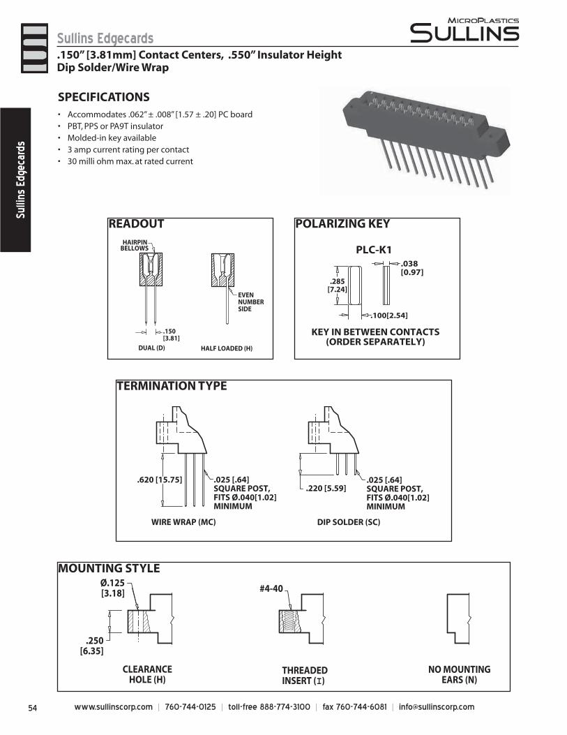
www.sullinscorp.com | 760-744-0125 | toll-free 888-774-3100 | fax 760-744-6081 | [email protected]
Sullins EdgecardsSu
llins
Edg
ecar
ds
TERMINATION TYPE
MOUNTING STYLE
READOUT
HALF LOADED (H)DUAL (D)
.150[3.81]
HAIRPINBELLOWS
EVENNUMBERSIDE
POLARIZING KEY
SPECIFICATIONSAcco• mmodates .062” ± .008” [1.57 ± .20] PC boardPBT, PPS or PA9T insulator • Molded-in key available• 3 amp current rating• per contact30 milli ohm max. at rated current•
WIRE WRAP (MC)
.620 [15.75] .025 [.64] SQUARE POST,FITS Ø.040[1.02]MINIMUM
DIP SOLDER (SC)
.220 [5.59].025 [.64] SQUARE POST,FITS Ø.040[1.02]MINIMUM
CLEARANCEHOLE (H)
THREADEDINSERT (I)
NO MOUNTINGEARS (N)
#4-40 Ø.125[3.18]
.250[6.35]
.150” [3.81mm] Contact Centers, .550” Insulator HeightDip Solder/Wire Wrap
PLC-K1
KEY IN BETWEEN CONTACTS(ORDER SEPARATELY)
.038[0.97]
.100[2.54]
.285[7.24]
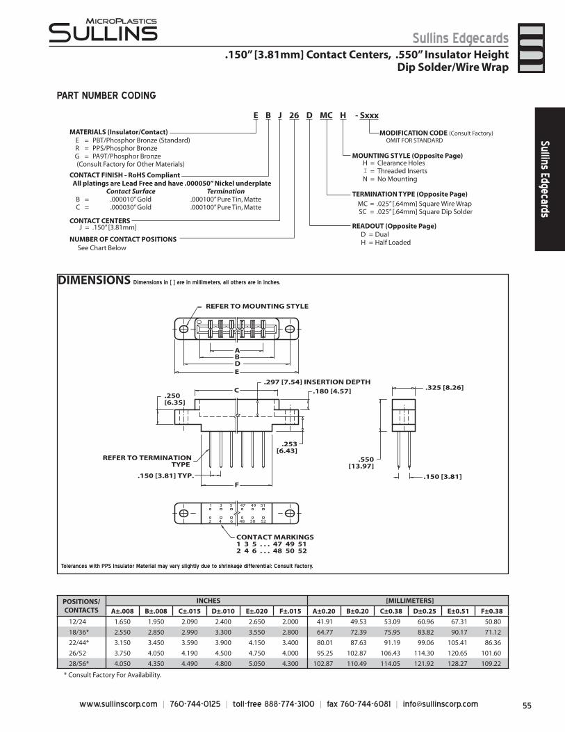
55www.sullinscorp.com | 760-744-0125 | toll-free 888-774-3100 | fax 760-744-6081 | [email protected]
Sullins EdgecardsSullins Edgecards
DIMENSIONS Dimensions in [ ] are in millimeters, all others are in inches.
.150” [3.81mm] Contact Centers, .550” Insulator HeightDip Solder/Wire Wrap
POSITIONS/CONTACTS
INCHES [MILLIMETERS]
A±.008 B±.008 C±.015 D±.010 E±.020 F±.015 A±0.20 B±0.20 C±0.38 D±0.25 E±0.51 F±0.38
12/24 1.650 1.950 2.090 2.400 2.650 2.000 41.91 49.53 53.09 60.96 67.31 50.80
18/36* 2.550 2.850 2.990 3.300 3.550 2.800 64.77 72.39 75.95 83.82 90.17 71.12
22/44* 3.150 3.450 3.590 3.900 4.150 3.400 80.01 87.63 91.19 99.06 105.41 86.36
26/52 3.750 4.050 4.190 4.500 4.750 4.000 95.25 102.87 106.43 114.30 120.65 101.60
28/56* 4.050 4.350 4.490 4.800 5.050 4.300 102.87 110.49 114.05 121.92 128.27 109.22
* Consult Factory For Availability.
1 3 5 47 49 51
2 4 6 48 50 52
AB
C
DE
F.150 [3.81] TYP.
.250[6.35]
.550[13.97]
.180 [4.57]
.253[6.43]
.297 [7.54] INSERTION DEPTH
REFER TO MOUNTING STYLE
.150 [3.81]
REFER TO TERMINATIONTYPE
CONTACT MARKINGS1 3 5 . . . 47 49 512 4 6 . . . 48 50 52
.325 [8.26]
PART NUMBER CODING
MATERIALS (Insulator/Contact)E = PBT/Phosphor Bronze (Standard)R = PPS/Phosphor BronzeG = PA9T/Phosphor Bronze (Consult Factory for Other Materials)
CONTACT FINISH - RoHS Compliant
CONTACT CENTERSJ = .150” [3.81mm]
NUMBER OF CONTACT POSITIONS
READOUT (Opposite Page)D = DualH = Half Loaded
MOUNTING STYLE (Opposite Page)H = Clearance HolesI = Threaded InsertsN = No Mounting
TERMINATION TYPE (Opposite Page)MC = .025” [.64mm] Square Wire WrapSC = .025” [.64mm] Square Dip Solder
MODIFICATION CODE (Consult Factory) OMIT FOR STANDARD
All platings are Lead Free and have .000050” Nickel underplateContact Surface Termination
B = .000010” Gold .000100” Pure Tin, MatteC = .000030” Gold .000100” Pure Tin, Matte
See Chart Below
E B J 26 D MC H - Sxxx
Tolerances with PPS Insulator Material may vary slightly due to shrinkage differential; Consult Factory.
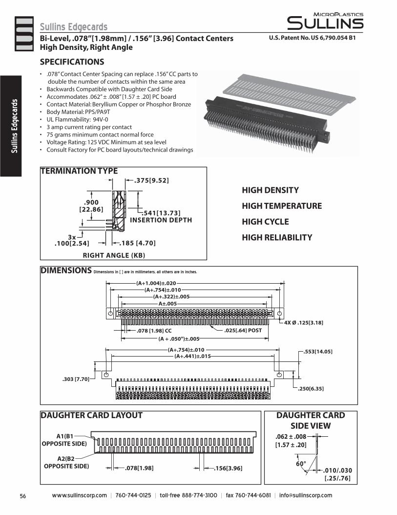
www.sullinscorp.com | 760-744-0125 | toll-free 888-774-3100 | fax 760-744-6081 | [email protected]
Sullins EdgecardsSu
llins
Edg
ecar
ds
DAUGHTER CARD LAYOUT DAUGHTER CARD SIDE VIEW
TERMINATION TYPE
DIMENSIONS Dimensions in [ ] are in millimeters, all others are in inches.
Bi-Level, .078”[1.98mm] / .156” [3.96] Contact CentersHigh Density, Right Angle
(A+.322)±.005
(A + .050")±.005
A±.005
(A+.441)±.015(A+.754)±.010
(A+.754)±.010(A+1.004)±.020
.078 [1.98] CC
.303 [7.70]
.553[14.05]
.250[6.35]
4X Ø .125[3.18]
.025[.64] POST
RIGHT ANGLE (KB)
.900[22.86]
.375[9.52]
.541[13.73]INSERTION DEPTH
.185 [4.70]3x
.100[2.54]
60°.010/.030[.25/.76]
.062 ± .008[1.57 ± .20]
.078[1.98]
A1(B1OPPOSITE SIDE)
A2(B2 OPPOSITE SIDE) .156[3.96]
U.S. Patent No. US 6,790.054 B1
SPECIFICATIONS.078• ” Contact Center Spacing can replace .156” CC parts to
double the number of contacts within the same areaBackwards Compatible with Daughter Card Side• Accommodates .062” ± .008” [1.57 ± .20] PC board• Contact Material: Beryllium Copper or Phosphor Bronze• Body Material: PPS/PA9T• UL Flammability: 94V-0• 3 amp current rating per contact• 75 grams minimum contact normal force• Voltage Rating: 125 VDC Minimum at sea level• Consult Factory for PC boar• d layouts/technical drawings
o
HIGH DENSITY
HIGH TEMPERATURE
HIGH CYCLE
HIGH RELIABILITY
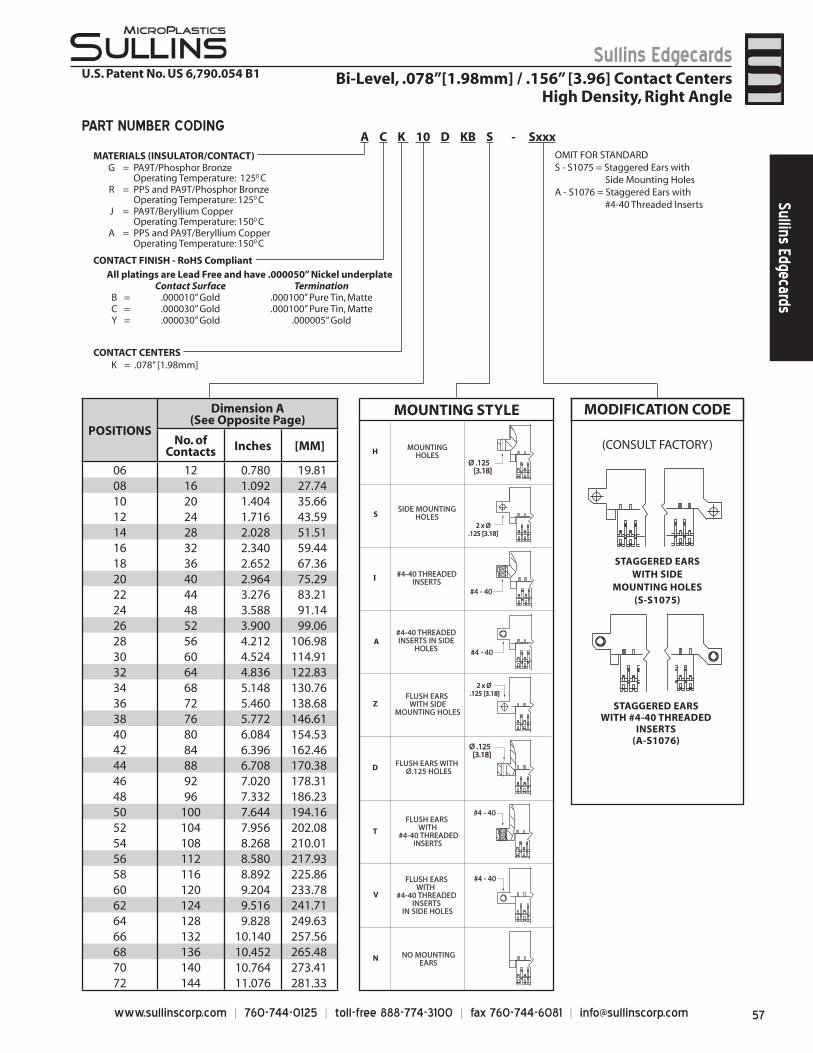
57www.sullinscorp.com | 760-744-0125 | toll-free 888-774-3100 | fax 760-744-6081 | [email protected]
Sullins EdgecardsSullins Edgecards
Bi-Level, .078”[1.98mm] / .156” [3.96] Contact CentersHigh Density, Right Angle
POSITIONS
Dimension A(See Opposite Page)
No. ofContacts Inches [MM]
06 12 0.780 19.81 08 16 1.092 27.7410 20 1.404 35.6612 24 1.716 43.5914 28 2.028 51.5116 32 2.340 59.4418 36 2.652 67.3620 40 2.964 75.2922 44 3.276 83.2124 48 3.588 91.1426 52 3.900 99.0628 56 4.212 106.9830 60 4.524 114.9132 64 4.836 122.8334 68 5.148 130.7636 72 5.460 138.6838 76 5.772 146.6140 80 6.084 154.5342 84 6.396 162.4644 88 6.708 170.3846 92 7.020 178.3148 96 7.332 186.2350 100 7.644 194.1652 104 7.956 202.0854 108 8.268 210.0156 112 8.580 217.9358 116 8.892 225.8660 120 9.204 233.7862 124 9.516 241.7164 128 9.828 249.6366 132 10.140 257.5668 136 10.452 265.4870 140 10.764 273.4172 144 11.076 281.33
CONTACT CENTERSK = .078” [1.98mm]
A C K 10 D KB S - SxxxPART NUMBER CODING
U.S. Patent No. US 6,790.054 B1
MATERIALS (INSULATOR/CONTACT)
CONTACT FINISH - RoHS Compliant
OMIT FOR STANDARDS - S1075 = Staggered Ears with Side Mounting HolesA - S1076 = Staggered Ears with #4-40 Threaded Inserts
All platings are Lead Free and have .000050” Nickel underplateContact Surface Termination
B = .000010” Gold .000100” Pure Tin, MatteC = .000030” Gold .000100” Pure Tin, MatteY = .000030” Gold .000005” Gold
G = PA9T/Phosphor BronzeOperating Temperature: 1250 C
R = PPS and PA9T/Phosphor BronzeOperating Temperature: 1250 C
J = PA9T/Beryllium CopperOperating Temperature: 1500 C
A = PPS and PA9T/Beryllium Copper Operating Temperature: 1500 C
STAGGERED EARSWITH SIDE
MOUNTING HOLES(S-S1075)
STAGGERED EARSWITH #4-40 THREADED
INSERTS(A-S1076)
(CONSULT FACTORY)
MODIFICATION CODE
#4 - 40
FLUSH EARS WITH SIDE
MOUNTING HOLES
FLUSH EARS WITH Ø.125 HOLES
FLUSH EARS WITH
#4-40 THREADED INSERTS
IN SIDE HOLES
#4-40 THREADEDINSERTS IN SIDE
HOLES
#4-40 THREADEDINSERTS
FLUSH EARS WITH
#4-40 THREADEDINSERTS
MOUNTINGHOLES
SIDE MOUNTINGHOLES
NO MOUNTINGEARS
Z
D
T
V
H
S
I
A
N
ØØ ..112255 [[33..1188]]
#4 - 40
#4 - 40
ØØ ..112255 [[33..1188]]
#4 - 40
22 xx ØØ ..112255 [[33..1188]]
22 xx ØØ..112255 [[33..1188]]
MOUNTING STYLE
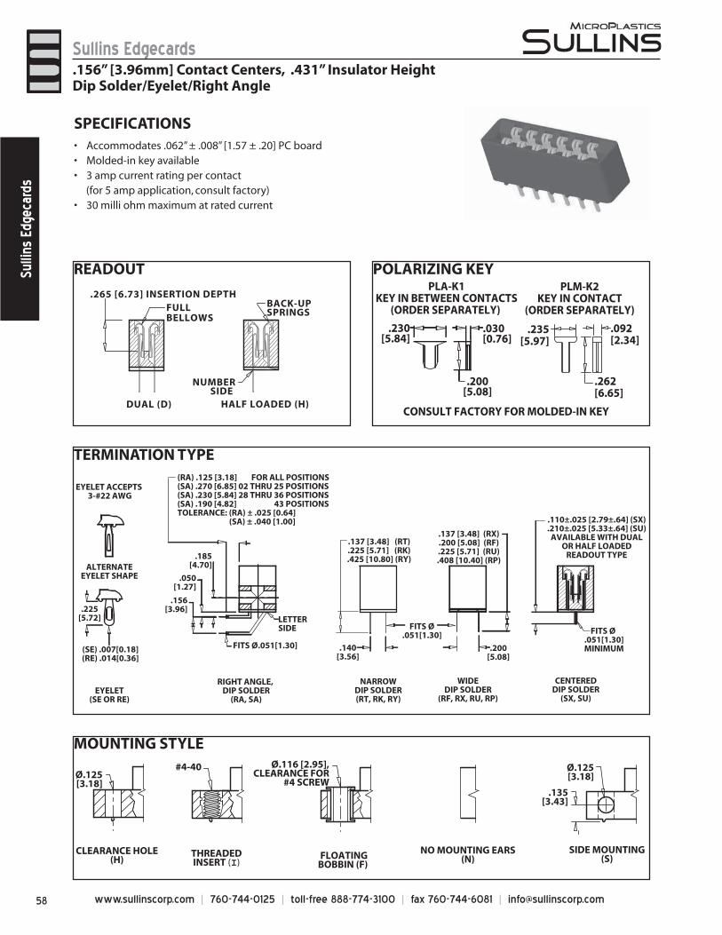
www.sullinscorp.com | 760-744-0125 | toll-free 888-774-3100 | fax 760-744-6081 | [email protected]
Sullins EdgecardsSu
llins
Edg
ecar
ds
READOUT
TERMINATION TYPE
POLARIZING KEY
MOUNTING STYLE
.265 [6.73] INSERTION DEPTH
DUAL (D)
FULLBELLOWS
HALF LOADED (H)
BACK-UPSPRINGS
NUMBERSIDE
PLM-K2KEY IN CONTACT
(ORDER SEPARATELY)
.235[5.97]
.092[2.34]
.262[6.65]
CONSULT FACTORY FOR MOLDED-IN KEY
PLA-K1KEY IN BETWEEN CONTACTS
(ORDER SEPARATELY)
.230[5.84]
.030[0.76]
.200[5.08]
SPECIFICATIONSAccom• modates .062” ± .008” [1.57 ± .20] PC boardMolded-in key available• 3 amp current rating• per contact
(for 5 amp application, consult factory)30 milli ohm maximum at rated current•
(RA) .125 [3.18] FOR ALL POSITIONS(SA) .270 [6.85] 02 THRU 25 POSITIONS(SA) .230 [5.84] 28 THRU 36 POSITIONS(SA) .190 [4.82] 43 POSITIONSTOLERANCE: (RA) ± .025 [0.64] (SA) ± .040 [1.00]
ALTERNATEEYELET SHAPE
EYELET(SE OR RE)
(SE) .007[0.18](RE) .014[0.36]
LETTERSIDE
.185[4.70]
.156[3.96]
.050[1.27]
RIGHT ANGLE, DIP SOLDER
(RA, SA)
FITS Ø.051[1.30] .200[5.08]
NARROWDIP SOLDER(RT, RK, RY)
WIDEDIP SOLDER
(RF, RX, RU, RP)
.140[3.56]
.137 [3.48] (RT)
.225 [5.71] (RK).425 [10.80] (RY)
FITS Ø.051[1.30]
.137 [3.48] (RX)
.200 [5.08] (RF).225 [5.71] (RU).408 [10.40] (RP)
CENTEREDDIP SOLDER
(SX, SU)
.110±.025 [2.79±.64] (SX)
.210±.025 [5.33±.64] (SU)AVAILABLE WITH DUAL
OR HALF LOADEDREADOUT TYPE
EYELET ACCEPTS 3-#22 AWG
.225[5.72]
FITS Ø .051[1.30]MINIMUM
Ø.125[3.18]
#4-40
.135[3.43]
CLEARANCE HOLE(H)
THREADEDINSERT (I)
FLOATINGBOBBIN (F)
NO MOUNTING EARS(N)
SIDE MOUNTING(S)
Ø.116 [2.95],CLEARANCE FOR
#4 SCREW
Ø.125[3.18]
.156” [3.96mm] Contact Centers, .431” Insulator HeightDip Solder/Eyelet/Right Angle
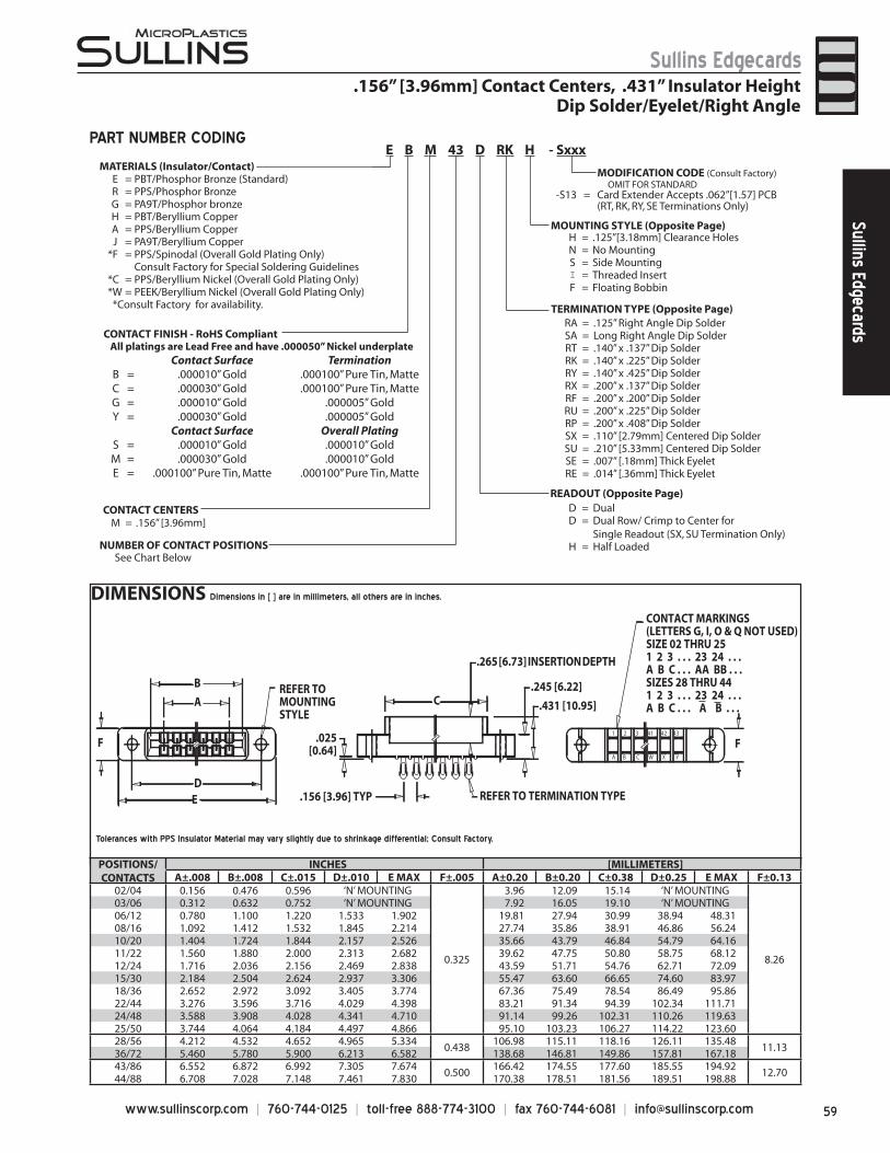
59www.sullinscorp.com | 760-744-0125 | toll-free 888-774-3100 | fax 760-744-6081 | [email protected]
Sullins EdgecardsSullins Edgecards
.156” [3.96mm] Contact Centers, .431” Insulator HeightDip Solder/Eyelet/Right Angle
DIMENSIONS Dimensions in [ ] are in millimeters, all others are in inches.
REFER TOMOUNTINGSTYLE
1 2 3 41 42 43
_ _ _ A B C W X Y
F
A
BC
D E .156 [3.96] TYP
.025[0.64]
REFER TO TERMINATION TYPE
.431 [10.95]
.245 [6.22]
.265 [6.73] INSERTION DEPTH
F
CONTACT MARKINGS(LETTERS G, I, O & Q NOT USED)SIZE 02 THRU 251 2 3 . . . 23 24 . . .A B C . . . AA BB . . .SIZES 28 THRU 441 2 3 . . . 23 24 . . .A B C . . . A B . . .
PART NUMBER CODING
MATERIALS (Insulator/Contact)
CONTACT CENTERSM = .156” [3.96mm]
NUMBER OF CONTACT POSITIONS
READOUT (Opposite Page)D = DualD = Dual Row/ Crimp to Center for
Single Readout (SX, SU Termination Only)H = Half Loaded
MOUNTING STYLE (Opposite Page)H = .125”[3.18mm] Clearance HolesN = No MountingS = Side MountingI = Threaded InsertF = Floating Bobbin
TERMINATION TYPE (Opposite Page)RA = .125” Right Angle Dip SolderSA = Long Right Angle Dip SolderRT = .140” x .137” Dip SolderRK = .140” x .225” Dip SolderRY = .140” x .425” Dip SolderRX = .200” x .137” Dip SolderRF = .200” x .200” Dip SolderRU = .200” x .225” Dip SolderRP = .200” x .408” Dip SolderSX = .110” [2.79mm] Centered Dip SolderSU = .210” [5.33mm] Centered Dip SolderSE = .007” [.18mm] Thick Eyelet RE = .014” [.36mm] Thick Eyelet
MODIFICATION CODE (Consult Factory) OMIT FOR STANDARD
-S13 = Card Extender Accepts .062”[1.57] PCB(RT, RK, RY, SE Terminations Only)
See Chart Below
E B M 43 D RK H - Sxxx
Tolerances with PPS Insulator Material may vary slightly due to shrinkage differential; Consult Factory.
All platings are Lead Free and have .000050” Nickel underplate Contact Surface Termination
B = .000010” Gold .000100” Pure Tin, MatteC = .000030” Gold .000100” Pure Tin, MatteG = .000010” Gold .000005” GoldY = .000030” Gold .000005” Gold
Contact Surface Overall PlatingS = .000010” Gold .000010” GoldM = .000030” Gold .000010” GoldE = .000100” Pure Tin, Matte .000100” Pure Tin, Matte
CONTACT FINISH - RoHS Compliant
POSITIONS/CONTACTS
INCHES [MILLIMETERS]A±.008 B±.008 C±.015 D±.010 E MAX F±.005 A±0.20 B±0.20 C±0.38 D±0.25 E MAX F±0.13
02/04 0.156 0.476 0.596 ‘N’ MOUNTING
0.325
3.96 12.09 15.14 ‘N’ MOUNTING
8.26
03/06 0.312 0.632 0.752 ‘N’ MOUNTING 7.92 16.05 19.10 ‘N’ MOUNTING06/12 0.780 1.100 1.220 1.533 1.902 19.81 27.94 30.99 38.94 48.3108/16 1.092 1.412 1.532 1.845 2.214 27.74 35.86 38.91 46.86 56.2410/20 1.404 1.724 1.844 2.157 2.526 35.66 43.79 46.84 54.79 64.1611/22 1.560 1.880 2.000 2.313 2.682 39.62 47.75 50.80 58.75 68.1212/24 1.716 2.036 2.156 2.469 2.838 43.59 51.71 54.76 62.71 72.0915/30 2.184 2.504 2.624 2.937 3.306 55.47 63.60 66.65 74.60 83.9718/36 2.652 2.972 3.092 3.405 3.774 67.36 75.49 78.54 86.49 95.8622/44 3.276 3.596 3.716 4.029 4.398 83.21 91.34 94.39 102.34 111.7124/48 3.588 3.908 4.028 4.341 4.710 91.14 99.26 102.31 110.26 119.6325/50 3.744 4.064 4.184 4.497 4.866 95.10 103.23 106.27 114.22 123.6028/56 4.212 4.532 4.652 4.965 5.334
0.438106.98 115.11 118.16 126.11 135.48
11.1336/72 5.460 5.780 5.900 6.213 6.582 138.68 146.81 149.86 157.81 167.1843/86 6.552 6.872 6.992 7.305 7.674
0.500166.42 174.55 177.60 185.55 194.92
12.7044/88 6.708 7.028 7.148 7.461 7.830 170.38 178.51 181.56 189.51 198.88
E = PBT/Phosphor Bronze (Standard)R = PPS/Phosphor BronzeG = PA9T/Phosphor bronzeH = PBT/Beryllium CopperA = PPS/Beryllium CopperJ = PA9T/Beryllium Copper
*F = PPS/Spinodal (Overall Gold Plating Only)Consult Factory for Special Soldering Guidelines
*C = PPS/Beryllium Nickel (Overall Gold Plating Only)*W = PEEK/Beryllium Nickel (Overall Gold Plating Only) *Consult Factory for availability.
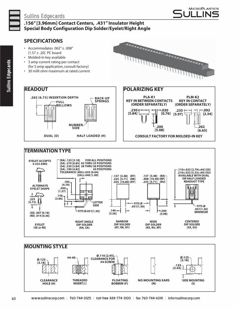
www.sullinscorp.com | 760-744-0125 | toll-free 888-774-3100 | fax 760-744-6081 | [email protected]
Sullins EdgecardsSu
llins
Edg
ecar
ds
READOUT
TERMINATION TYPE
POLARIZING KEY
MOUNTING STYLE
.265 [6.73] INSERTION DEPTH
DUAL (D)
FULL BELLOWS
HALF LOADED (H)
BACK-UPSPRINGS
NUMBERSIDE
(RA) .125 [3.18] FOR ALL POSITIONS(SA) .270 [6.85] 02 THRU 25 POSITIONS(SA) .230 [5.84] 28 THRU 36 POSITIONS(SA) .190 [4.82] 43 POSITIONSTOLERANCE: (RA)±.025 [0.64] (SA)±.040 [1.00]
ALTERNATEEYELET SHAPE
EYELET(SE or RE)
(SE) .007 [0.18](RE) .014 [0.36]
LETTERSIDE
.156[3.96]
RIGHT ANGLEDIP SOLDER
(RA, SA)
FITS Ø.051[1.30] .200[5.08]
NARROWDIP SOLDER(RT, RK, RY)
WIDEDIP SOLDER(RX, RU, RP)
.140[3.56]
.137 [3.48] (RT)
.225 [5.71] (RK)
.425 [10.80] (RY)
FITS Ø.051[1.30]
.137 [3.48] (RX)
.408 [10.40] (RP)
.225 [5.71] (RU)
CENTEREDDIP SOLDER
(SX, SU)
.110±.025 [2.79±.64] (SX)
.210±.025 [5.33±.64] (SU)AVAILABLE WITH DUAL
OR HALF LOADEDREADUOT TYPE
EYELET ACCEPTS3-#22 AWG
.225[5.72]
.050[1.27]
.185[4.70]
FITS Ø.051[1.30]MINIMUM
Ø.125[3.18]
#4-40 Ø.125[3.18]
.135[3.43]
CLEARANCEHOLE (H)
THREADEDINSERT(I)
FLOATINGBOBBIN (F)
NO MOUNTING EARS(N)
SIDE MOUNTING(S)
Ø.116 [2.95],CLEARANCE FOR
#4 SCREW
SPECIFICATIONSA• ccommodates .062” ± .008”
[1.57 ± .20] PC boardMolded-in key available• 3 amp current rating• per contact
(for 5 amp application, consult factory)30 milli ohm maximum at rated current•
.156” [3.96mm] Contact Centers, .431” Insulator HeightSpecial Body Configuration Dip Solder/Eyelet/Right Angle
PLM-K2KEY IN CONTACT
(ORDER SEPARATELY)
.235[5.97]
.092[2.34]
.262[6.65]
CONSULT FACTORY FOR MOLDED-IN KEY
PLA-K1KEY IN BETWEEN CONTACTS
(ORDER SEPARATELY)
.230[5.84]
.030[0.76]
.200[5.08]
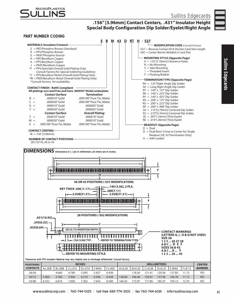
61www.sullinscorp.com | 760-744-0125 | toll-free 888-774-3100 | fax 760-744-6081 | [email protected]
Sullins EdgecardsSullins Edgecards
DIMENSIONS Dimensions in [ ] are in millimeters, all others are in inches.
MATERIALS (Insulator/Contact)
CONTACT FINISH - RoHS Compliant
CONTACT CENTERSM = .156” [3.96mm]
NUMBER OF CONTACT POSITIONS28 (14/14), 36 or 43
H = .125”[3.18mm] Clearance HolesN = No MountingS = Side MountingI = Threaded InsertF = Floating Bobbin
RA = .125” Right Angle Dip SolderSA = Long Right Angle Dip SolderRT = .140” x .137” Dip SolderRK = .140” x .225” Dip SolderRY = .140” x .425” Dip SolderRX = .200” x .137” Dip SolderRU = .200” x .225” Dip SolderRP = .200” x .408” Dip SolderSX = .110”[2.79mm] Centered Dip SolderSU = .210”[5.33mm] Centered Dip SolderSE = .007”[.18mm] Thick EyeletRE = .014”[.36mm] Thick Eyelet
MODIFICATION CODE (Consult Factory) -S37 = Reverse Contact ID & Shorter Card Slot Length
-S92 = Center Barrier Molded in Card Slot
READOUT (Opposite Page)
MOUNTING STYLE (Opposite Page)
TERMINATION TYPE (Opposite Page)
E = PBT/Phosphor Bronze (Standard)R = PPS/Phosphor BronzeG = PA9T/Phosphor bronzeH = PBT/Beryllium CopperA = PPS/Beryllium CopperJ = PA9T/Beryllium Copper
*F = PPS/Spinodal (Overall Gold Plating Only)Consult Factory for Special Soldering Guidelines
*C = PPS/Beryllium Nickel (Overall Gold Plating Only)*W = PEEK/Beryllium Nickel (Overall Gold Plating Only) *Consult Factory for availability.
D = DualD = Dual Row/ Crimp to Center for Single
Readout (SX, SU Termination Only)H = Half Loaded
PART NUMBER CODING
1 2 3 4 5 6 7 8 9 10 11 12 13 14 15 16 17 18 19 20 21 22 23 24 25 26 27 28
_ _ _ _ _ _ A B C D E F H J K L M N P R S T U V W X Y Z A B C D E F
ABC
DE
F
2.028[51.51]2.028[51.51].280[7.11]
.140 [3.56], 2 PLS.
B
C
DE
F
36 OR 43 POSITIONS (-S37 MODIFICATION)
28 POSITIONS (-S92 MODIFICATION)
.265 [6.73] INSERTION DEPTH
.431[10.95]
.245[6.22]
.025[0.64]
.156 [3.96] TYP. REFER TO TERMINATION TYPE
REFER TO MOUNTING STYLE
KEY THICK .046 [1.17]
CONTACT MARKINGS(LETTERS G, I , O & Q NOT USED)SIZE 281 2 3 ... 26 27 28A B C ... D E F SIZES 36 & 43A B C ... R ... Y1 2 3 ... 36 ... 43
.156” [3.96mm] Contact Centers, .431” Insulator HeightSpecial Body Configuration Dip Solder/Eyelet/Right Angle
Tolerances with PPS Insulator Material may vary slightly due to shrinkage differential; Consult Factory.
E B M 43 D RT H - S37
All platings are Lead Free and have .000050” Nickel underplate Contact Surface Termination
B = .000010” Gold .000100” Pure Tin, MatteC = .000030” Gold .000100” Pure Tin, MatteG = .000010” Gold .000005” GoldY = .000030” Gold .000005” Gold
Contact Surface Overall PlatingS = .000010” Gold .000010” GoldM = .000030” Gold .000010” GoldE = .000100” Pure Tin, Matte .000100” Pure Tin, Matte
POSITIONS/CONTACTS
INCHES [MILLIMETERS] CENTERBARRIERA±.008 B±.008 C±.015 D±.010 E MAX F±.005 A±0.20 B±0.20 C±0.38 D±0.25 E MAX F±0.13
28/56 4.660 4.780 5.093 5.427 0.438 118.36 121.41 129.36 137.85 11.13 YES
36/72 5.460 5.766 5.906 6.219 6.566 0.438 138.68 146.46 150.01 157.96 166.78 11.13 NO
43/86 6.552 6.810 7.000 7.302 7.643 0.500 166.42 172.97 177.80 185.47 194.13 12.70 NO
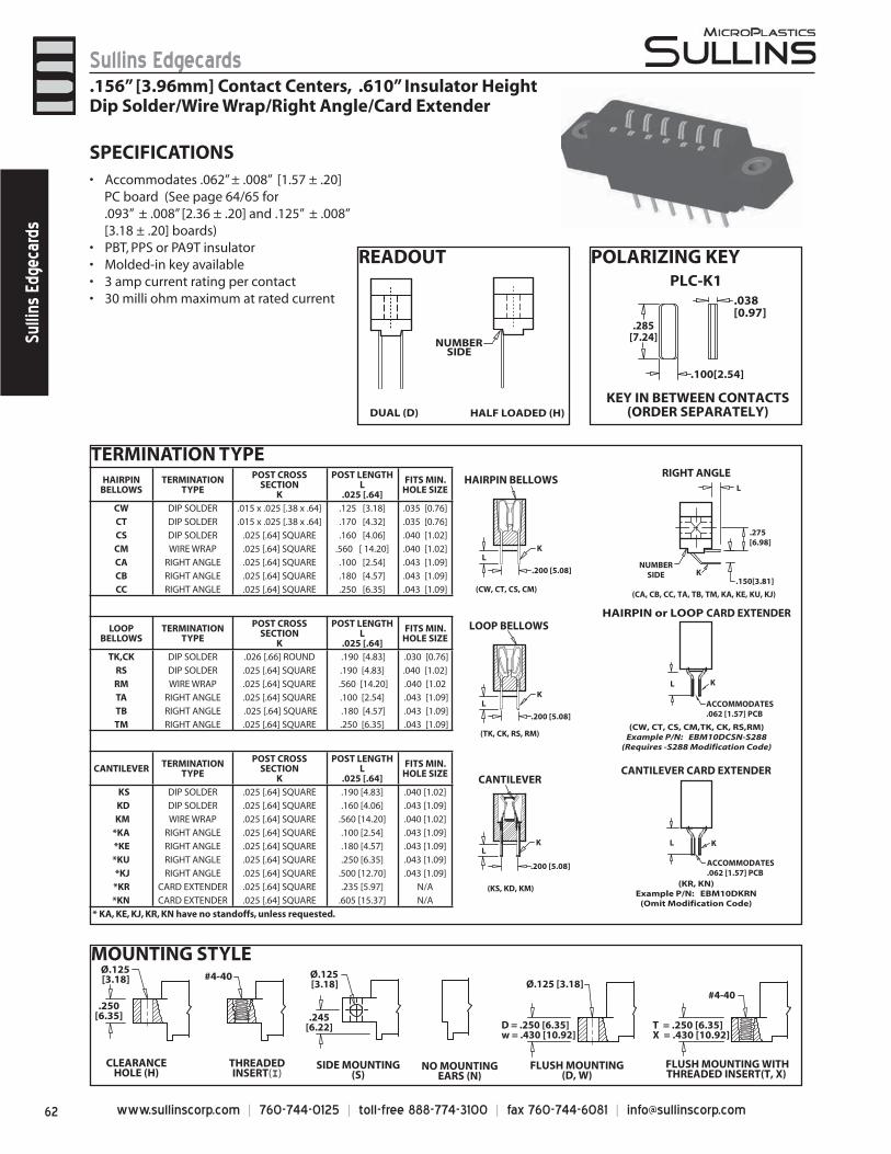
www.sullinscorp.com | 760-744-0125 | toll-free 888-774-3100 | fax 760-744-6081 | [email protected]
Sullins EdgecardsSu
llins
Edg
ecar
ds
READOUT POLARIZING KEY
TERMINATION TYPE
MOUNTING STYLE
DUAL (D) HALF LOADED (H)
NUMBER SIDE
SPECIFICATIONSAc• commodates .062” ± .008” [1.57 ± .20]
PC board (See page 64/65 for .093” ± .008” [2.36 ± .20] and .125” ± .008” [3.18 ± .20] boards)
PBT, PPS or PA9T insulator• Molded-in key available• 3 amp current rating• per contact30 milli ohm maximum at rated current•
SIDE MOUNTING(S)
.245[6.22]
Ø.125[3.18] Ø.125 [3.18]
D = .250 [6.35] w = .430 [10.92]
FLUSH MOUNTING(D, W)
FLUSH MOUNTING WITHTHREADED INSERT(T, X)
#4-40
THREADEDINSERT(I)
#4-40
NO MOUNTINGEARS (N)
Ø.125[3.18]
.250[6.35]
CLEARANCEHOLE (H)
T = .250 [6.35]X = .430 [10.92]
.156” [3.96mm] Contact Centers, .610” Insulator HeightDip Solder/Wire Wrap/Right Angle/Card Extender
CANTILEVER TERMINATION TYPE
POST CROSS SECTION
K
POST LENGTHL
.025 [.64]
FITS MIN. HOLE SIZE
KS DIP SOLDER .025 [.64] SQUARE .190 [4.83] .040 [1.02]
KD DIP SOLDER .025 [.64] SQUARE .160 [4.06] .043 [1.09]
KM WIRE WRAP .025 [.64] SQUARE .560 [14.20] .040 [1.02]
*KA RIGHT ANGLE .025 [.64] SQUARE .100 [2.54] .043 [1.09]
*KE RIGHT ANGLE .025 [.64] SQUARE .180 [4.57] .043 [1.09]
*KU RIGHT ANGLE .025 [.64] SQUARE .250 [6.35] .043 [1.09]
*KJ RIGHT ANGLE .025 [.64] SQUARE .500 [12.70] .043 [1.09]
*KR CARD EXTENDER .025 [.64] SQUARE .235 [5.97] N/A
*KN CARD EXTENDER .025 [.64] SQUARE .605 [15.37] N/A
* KA, KE, KJ, KR, KN have no standoffs, unless requested.
HAIRPIN BELLOWS
TERMINATION TYPE
POST CROSS SECTION
K
POST LENGTHL
.025 [.64]
FITS MIN. HOLE SIZE
CW DIP SOLDER .015 x .025 [.38 x .64] .125 [3.18] .035 [0.76]
CT DIP SOLDER .015 x .025 [.38 x .64] .170 [4.32] .035 [0.76]
CS DIP SOLDER .025 [.64] SQUARE .160 [4.06] .040 [1.02]
CM WIRE WRAP .025 [.64] SQUARE .560 [ 14.20] .040 [1.02]
CA RIGHT ANGLE .025 [.64] SQUARE .100 [2.54] .043 [1.09]
CB RIGHT ANGLE .025 [.64] SQUARE .180 [4.57] .043 [1.09]
CC RIGHT ANGLE .025 [.64] SQUARE .250 [6.35] .043 [1.09]
LOOP BELLOWS
TERMINATION TYPE
POST CROSS SECTION
K
POST LENGTHL
.025 [.64]
FITS MIN. HOLE SIZE
TK,CK DIP SOLDER .026 [.66] ROUND .190 [4.83] .030 [0.76]
RS DIP SOLDER .025 [.64] SQUARE .190 [4.83] .040 [1.02]
RM WIRE WRAP .025 [.64] SQUARE .560 [14.20] .040 [1.02
TA RIGHT ANGLE .025 [.64] SQUARE .100 [2.54] .043 [1.09]
TB RIGHT ANGLE .025 [.64] SQUARE .180 [4.57] .043 [1.09]
TM RIGHT ANGLE .025 [.64] SQUARE .250 [6.35] .043 [1.09]
(CW, CT, CS, CM)
HAIRPIN BELLOWS
LK
(TK, CK, RS, RM)
LOOP BELLOWS
(KS, KD, KM)
CANTILEVER
(CA, CB, CC, TA, TB, TM, KA, KE, KU, KJ)
NUMBERSIDE
L
.275[6.98]
.150[3.81]
RIGHT ANGLE
(CW, CT, CS, CM,TK, CK, RS,RM)Example P/N: EBM10DCSN-S288
(Requires -S288 Modification Code)
ACCOMMODATES.062 [1.57] PCB
HAIRPIN or LOOP CARD EXTENDER
L K
(KR, KN)Example P/N: EBM10DKRN
(Omit Modification Code)
ACCOMMODATES.062 [1.57] PCB
L K
CANTILEVER CARD EXTENDER
K.200 [5.08]
K
.200 [5.08]
L
LK
.200 [5.08]
PLC-K1
KEY IN BETWEEN CONTACTS(ORDER SEPARATELY)
.038[0.97]
.100[2.54]
.285[7.24]
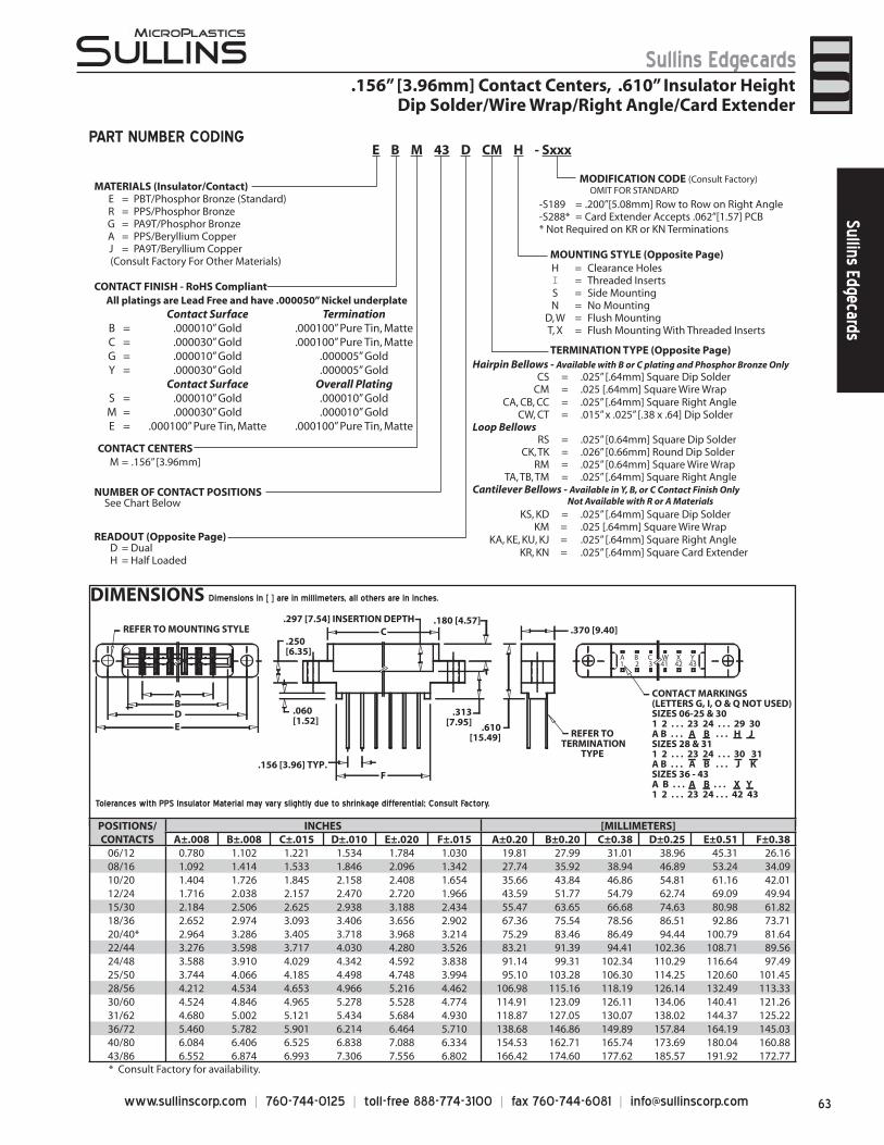
63www.sullinscorp.com | 760-744-0125 | toll-free 888-774-3100 | fax 760-744-6081 | [email protected]
Sullins EdgecardsSullins Edgecards
DIMENSIONS Dimensions in [ ] are in millimeters, all others are in inches.
* Consult Factory for availability.
CONTACT MARKINGS(LETTERS G, I, O & Q NOT USED)SIZES 06-25 & 301 2 . . . 23 24 . . . 29 30A B . . . A B . . . H JSIZES 28 & 311 2 . . . 23 24 . . . 30 31A B . . . A B . . . J KSIZES 36 - 43A B . . . A B . . . X Y1 2 . . . 23 24 . . . 42 43
A B C W X Y1 2 3 41 42 43
.370 [9.40]
AB
C
DE
F.156 [3.96] TYP.
.060[1.52]
.250[6.35]
.180 [4.57]
.313[7.95]
.297 [7.54] INSERTION DEPTHREFER TO MOUNTING STYLE
REFER TO TERMINATION
TYPE
.610[15.49]
_ _ _
Tolerances with PPS Insulator Material may vary slightly due to shrinkage differential; Consult Factory.
PART NUMBER CODING
.156” [3.96mm] Contact Centers, .610” Insulator HeightDip Solder/Wire Wrap/Right Angle/Card Extender
MATERIALS (Insulator/Contact)E = PBT/Phosphor Bronze (Standard)R = PPS/Phosphor BronzeG = PA9T/Phosphor BronzeA = PPS/Beryllium CopperJ = PA9T/Beryllium Copper
(Consult Factory For Other Materials)
CONTACT FINISH - RoHS Compliant
CONTACT CENTERSM = .156” [3.96mm]
NUMBER OF CONTACT POSITIONS
READOUT (Opposite Page)D = DualH = Half Loaded
MOUNTING STYLE (Opposite Page)
TERMINATION TYPE (Opposite Page)
MODIFICATION CODE (Consult Factory) OMIT FOR STANDARD
See Chart Below
-S189 = .200”[5.08mm] Row to Row on Right Angle-S288* = Card Extender Accepts .062”[1.57] PCB* Not Required on KR or KN Terminations
H = Clearance HolesI = Threaded InsertsS = Side MountingN = No Mounting
D, W = Flush MountingT, X = Flush Mounting With Threaded Inserts
Hairpin Bellows - Available with B or C plating and Phosphor Bronze OnlyCS = .025” [.64mm] Square Dip Solder
CM = .025 [.64mm] Square Wire WrapCA, CB, CC = .025” [.64mm] Square Right Angle
CW, CT = .015” x .025” [.38 x .64] Dip SolderLoop Bellows
RS = .025” [0.64mm] Square Dip SolderCK, TK = .026” [0.66mm] Round Dip Solder
RM = .025” [0.64mm] Square Wire WrapTA, TB, TM = .025” [.64mm] Square Right Angle
Cantilever Bellows - Available in Y, B, or C Contact Finish Only Not Available with R or A Materials
KS, KD = .025” [.64mm] Square Dip SolderKM = .025 [.64mm] Square Wire Wrap
KA, KE, KU, KJ = .025” [.64mm] Square Right AngleKR, KN = .025” [.64mm] Square Card Extender
E B M 43 D CM H - Sxxx
All platings are Lead Free and have .000050” Nickel underplate Contact Surface Termination
B = .000010” Gold .000100” Pure Tin, MatteC = .000030” Gold .000100” Pure Tin, MatteG = .000010” Gold .000005” GoldY = .000030” Gold .000005” Gold
Contact Surface Overall PlatingS = .000010” Gold .000010” GoldM = .000030” Gold .000010” GoldE = .000100” Pure Tin, Matte .000100” Pure Tin, Matte
POSITIONS/CONTACTS
INCHES [MILLIMETERS]A±.008 B±.008 C±.015 D±.010 E±.020 F±.015 A±0.20 B±0.20 C±0.38 D±0.25 E±0.51 F±0.38
06/12 0.780 1.102 1.221 1.534 1.784 1.030 19.81 27.99 31.01 38.96 45.31 26.1608/16 1.092 1.414 1.533 1.846 2.096 1.342 27.74 35.92 38.94 46.89 53.24 34.0910/20 1.404 1.726 1.845 2.158 2.408 1.654 35.66 43.84 46.86 54.81 61.16 42.0112/24 1.716 2.038 2.157 2.470 2.720 1.966 43.59 51.77 54.79 62.74 69.09 49.9415/30 2.184 2.506 2.625 2.938 3.188 2.434 55.47 63.65 66.68 74.63 80.98 61.8218/36 2.652 2.974 3.093 3.406 3.656 2.902 67.36 75.54 78.56 86.51 92.86 73.7120/40* 2.964 3.286 3.405 3.718 3.968 3.214 75.29 83.46 86.49 94.44 100.79 81.6422/44 3.276 3.598 3.717 4.030 4.280 3.526 83.21 91.39 94.41 102.36 108.71 89.5624/48 3.588 3.910 4.029 4.342 4.592 3.838 91.14 99.31 102.34 110.29 116.64 97.4925/50 3.744 4.066 4.185 4.498 4.748 3.994 95.10 103.28 106.30 114.25 120.60 101.4528/56 4.212 4.534 4.653 4.966 5.216 4.462 106.98 115.16 118.19 126.14 132.49 113.3330/60 4.524 4.846 4.965 5.278 5.528 4.774 114.91 123.09 126.11 134.06 140.41 121.2631/62 4.680 5.002 5.121 5.434 5.684 4.930 118.87 127.05 130.07 138.02 144.37 125.2236/72 5.460 5.782 5.901 6.214 6.464 5.710 138.68 146.86 149.89 157.84 164.19 145.0340/80 6.084 6.406 6.525 6.838 7.088 6.334 154.53 162.71 165.74 173.69 180.04 160.8843/86 6.552 6.874 6.993 7.306 7.556 6.802 166.42 174.60 177.62 185.57 191.92 172.77
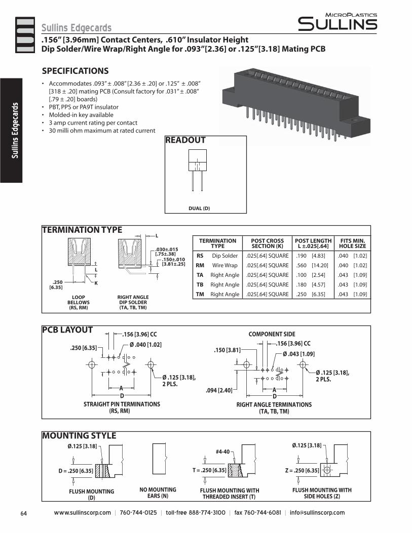
www.sullinscorp.com | 760-744-0125 | toll-free 888-774-3100 | fax 760-744-6081 | [email protected]
Sullins EdgecardsSu
llins
Edg
ecar
ds
MOUNTING STYLE
READOUT
DUAL (D)
PCB LAYOUT
RIGHT ANGLE TERMINATIONS(TA, TB, TM)
STRAIGHT PIN TERMINATIONS(RS, RM)
COMPONENT SIDE
.156 [3.96] CC.150 [3.81]
.094 [2.40]
Ø .043 [1.09]
Ø .125 [3.18],2 PLS.
.250 [6.35]
.156 [3.96] CC
Ø .040 [1.02]
AD
AD
Ø .125 [3.18],2 PLS.
T = .250 [6.35]
Ø.125 [3.18]
D = .250 [6.35]
FLUSH MOUNTING(D)
FLUSH MOUNTING WITHTHREADED INSERT (T)
#4-40
NO MOUNTINGEARS (N)
Ø.125 [3.18]
Z = .250 [6.35]
FLUSH MOUNTING WITHSIDE HOLES (Z)
SPECIFICATIONSAc• commodates .093” ± .008” [2.36 ± .20] or .125” ± .008”
[318 ± .20] mating PCB (Consult factory for .031” ± .008” [.79 ± .20] boards)
PBT, PPS or PA9T insulator• Molded-in key available• 3 amp current rating• per contact30 milli ohm maximum at rated current•
TERMINATION TYPE
RIGHT ANGLEDIP SOLDER(TA, TB, TM)
LOOPBELLOWS(RS, RM)
.250[6.35]
.030±.015[.75±.38]
.150±.010[3.81±.25]
L
L
K
TERMINATION TYPE
POST CROSS SECTION (K)
POST LENGTHL ±.025[.64]
FITS MIN. HOLE SIZE
RS Dip Solder .025[.64] SQUARE .190 [4.83] .040 [1.02]
RM Wire Wrap .025[.64] SQUARE .560 [14.20] .040 [1.02]
TA Right Angle .025[.64] SQUARE .100 [2.54] .043 [1.09]
TB Right Angle .025[.64] SQUARE .180 [4.57] .043 [1.09]
TM Right Angle .025[.64] SQUARE .250 [6.35] .043 [1.09]
.156” [3.96mm] Contact Centers, .610” Insulator HeightDip Solder/Wire Wrap/Right Angle for .093”[2.36] or .125”[3.18] Mating PCB
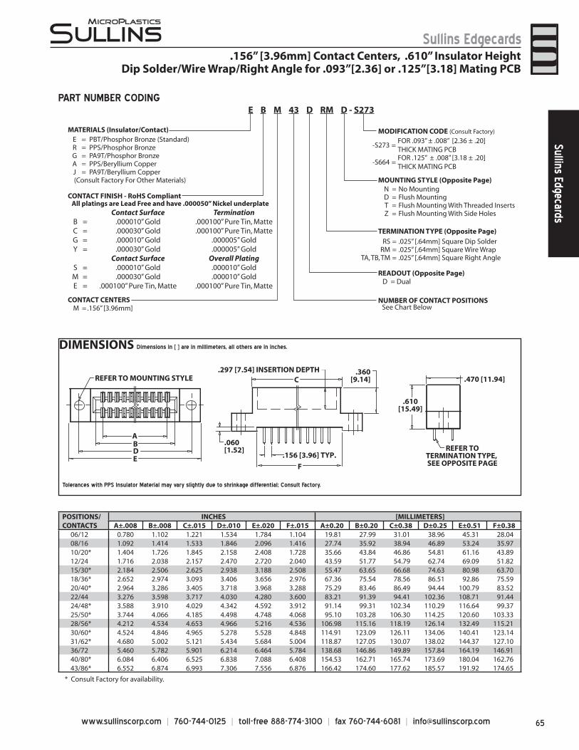
65www.sullinscorp.com | 760-744-0125 | toll-free 888-774-3100 | fax 760-744-6081 | [email protected]
Sullins EdgecardsSullins Edgecards
POSITIONS/CONTACTS
INCHES [MILLIMETERS]A±.008 B±.008 C±.015 D±.010 E±.020 F±.015 A±0.20 B±0.20 C±0.38 D±0.25 E±0.51 F±0.38
06/12 0.780 1.102 1.221 1.534 1.784 1.104 19.81 27.99 31.01 38.96 45.31 28.0408/16 1.092 1.414 1.533 1.846 2.096 1.416 27.74 35.92 38.94 46.89 53.24 35.9710/20* 1.404 1.726 1.845 2.158 2.408 1.728 35.66 43.84 46.86 54.81 61.16 43.8912/24 1.716 2.038 2.157 2.470 2.720 2.040 43.59 51.77 54.79 62.74 69.09 51.8215/30* 2.184 2.506 2.625 2.938 3.188 2.508 55.47 63.65 66.68 74.63 80.98 63.7018/36* 2.652 2.974 3.093 3.406 3.656 2.976 67.36 75.54 78.56 86.51 92.86 75.5920/40* 2.964 3.286 3.405 3.718 3.968 3.288 75.29 83.46 86.49 94.44 100.79 83.5222/44 3.276 3.598 3.717 4.030 4.280 3.600 83.21 91.39 94.41 102.36 108.71 91.4424/48* 3.588 3.910 4.029 4.342 4.592 3.912 91.14 99.31 102.34 110.29 116.64 99.3725/50* 3.744 4.066 4.185 4.498 4.748 4.068 95.10 103.28 106.30 114.25 120.60 103.3328/56* 4.212 4.534 4.653 4.966 5.216 4.536 106.98 115.16 118.19 126.14 132.49 115.2130/60* 4.524 4.846 4.965 5.278 5.528 4.848 114.91 123.09 126.11 134.06 140.41 123.1431/62* 4.680 5.002 5.121 5.434 5.684 5.004 118.87 127.05 130.07 138.02 144.37 127.1036/72 5.460 5.782 5.901 6.214 6.464 5.784 138.68 146.86 149.89 157.84 164.19 146.9140/80* 6.084 6.406 6.525 6.838 7.088 6.408 154.53 162.71 165.74 173.69 180.04 162.7643/86* 6.552 6.874 6.993 7.306 7.556 6.876 166.42 174.60 177.62 185.57 191.92 174.65
* Consult Factory for availability.
DIMENSIONS Dimensions in [ ] are in millimeters, all others are in inches.
Tolerances with PPS Insulator Material may vary slightly due to shrinkage differential; Consult Factory.
MATERIALS (Insulator/Contact)
CONTACT FINISH - RoHS Compliant
CONTACT CENTERSM = .156” [3.96mm]
NUMBER OF CONTACT POSITIONS
READOUT (Opposite Page)D = Dual
MOUNTING STYLE (Opposite Page)N = No MountingD = Flush MountingT = Flush Mounting With Threaded InsertsZ = Flush Mounting With Side Holes
TERMINATION TYPE (Opposite Page)RS = .025” [.64mm] Square Dip Solder
RM = .025” [.64mm] Square Wire WrapTA, TB, TM = .025” [.64mm] Square Right Angle
-S273 =FOR .093” ± .008” [2.36 ± .20]THICK MATING PCB
-S664 =FOR .125” ± .008” [3.18 ± .20]THICK MATING PCB
MODIFICATION CODE (Consult Factory)
See Chart Below
E = PBT/Phosphor Bronze (Standard)R = PPS/Phosphor BronzeG = PA9T/Phosphor BronzeA = PPS/Beryllium CopperJ = PA9T/Beryllium Copper
(Consult Factory For Other Materials)
E B M 43 D RM D - S273PART NUMBER CODING
.156” [3.96mm] Contact Centers, .610” Insulator HeightDip Solder/Wire Wrap/Right Angle for .093”[2.36] or .125”[3.18] Mating PCB
REFER TO MOUNTING STYLE.297 [7.54] INSERTION DEPTH
.060[1.52]
.360[9.14]
F
.156 [3.96] TYP.
C
.610[15.49]
REFER TOTERMINATION TYPE, SEE OPPOSITE PAGE
.470 [11.94]
ABDE
All platings are Lead Free and have .000050” Nickel underplate Contact Surface Termination
B = .000010” Gold .000100” Pure Tin, MatteC = .000030” Gold .000100” Pure Tin, MatteG = .000010” Gold .000005” GoldY = .000030” Gold .000005” Gold
Contact Surface Overall PlatingS = .000010” Gold .000010” GoldM = .000030” Gold .000010” GoldE = .000100” Pure Tin, Matte .000100” Pure Tin, Matte
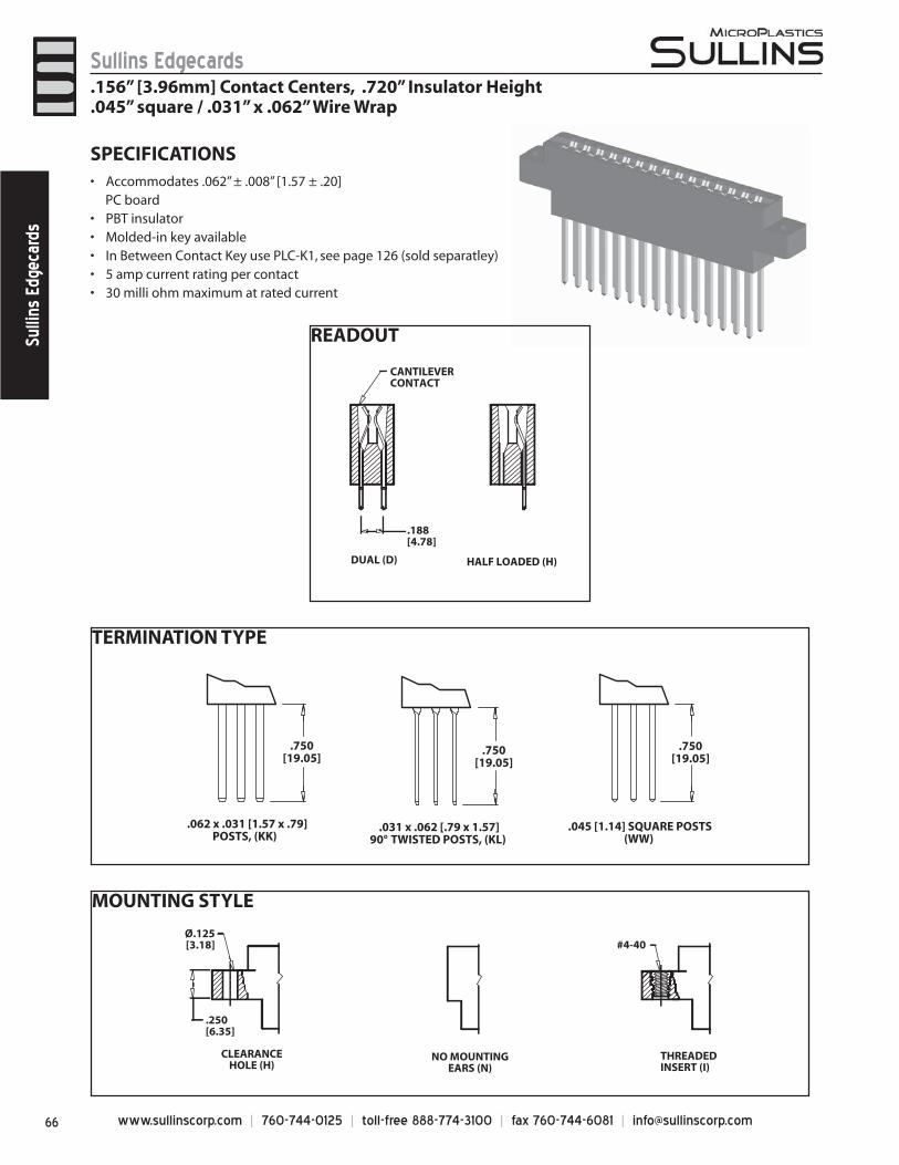
www.sullinscorp.com | 760-744-0125 | toll-free 888-774-3100 | fax 760-744-6081 | [email protected]
Sullins EdgecardsSu
llins
Edg
ecar
ds
TERMINATION TYPE
MOUNTING STYLE
READOUT
HALF LOADED (H)DUAL (D)
CANTILEVERCONTACT
.188[4.78]
.750[19.05]
.750[19.05]
.750[19.05]
.062 x .031 [1.57 x .79]POSTS, (KK)
.045 [1.14] SQUARE POSTS(WW)
.031 x .062 [.79 x 1.57]90° TWISTED POSTS, (KL)
CLEARANCEHOLE (H)
THREADEDINSERT (I)
NO MOUNTINGEARS (N)
Ø.125[3.18] #4-40
.250[6.35]
SPECIFICATIONSAccomm• odates .062” ± .008” [1.57 ± .20]
PC boardPBT insulator• Molded-in key available• In Between Contact Key use PLC-K1, see page 126 (sold separatley)• 5 amp current rating• per contact30 milli ohm maximum at rated current•
.156” [3.96mm] Contact Centers, .720” Insulator Height
.045” square / .031” x .062” Wire Wrap
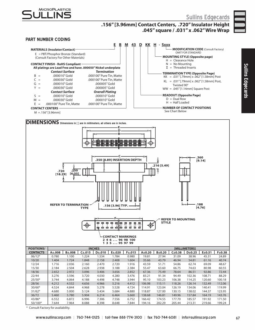
67www.sullinscorp.com | 760-744-0125 | toll-free 888-774-3100 | fax 760-744-6081 | [email protected]
Sullins EdgecardsSullins Edgecards
DIMENSIONS Dimensions in [ ] are in millimeters, all others are in inches.
.360[9.14]
.188[4.76]A
.216 [5.49]
.250[6.35]
.720[18.29]
B
C
ED
.350 [8.89] INSERTION DEPTH
REFER TO TERMINATIONTYPE
.156 [3.96] TYP.
2 4 6 8 10 92 94 96 98 100 1 3 5 7 9 91 93 95 97 99
CONTACT MARKINGS2 4 6 . . . 96 98 1001 3 5 . . . 95 97 99
REFER TO MOUNTINGSTYLE
F
MATERIALS (Insulator/Contact)
CONTACT FINISH - RoHS Compliant
CONTACT CENTERSM = .156” [3.96mm]
NUMBER OF CONTACT POSITIONS
READOUT (Opposite Page)D = Dual RowH = Half Loaded
MOUNTING STYLE (Opposite page)H = Clearance HoleN = No MountingI = Threaded Inserts
TERMINATION TYPE (Opposite Page)KK = .031” [.79mm] x .062” [1.58mm] Post
KL = .031” [.79mm] x .062” [1.58mm] Post, Twisted 90°
WW = .045” [1.14mm] Square Post
MODIFICATION CODE (Consult Factory) OMIT FOR STANDARD
See Chart Below
E = PBT/Phosphor Bronze (Standard) (Consult Factory For Other Materials)
E B M 43 D KK H - SxxxPART NUMBER CODING
.156” [3.96mm] Contact Centers, .720” Insulator Height.045” square / .031” x .062” Wire Wrap
POSITIONS/CONTACTS
INCHES [MILLIMETERS]A±.008 B±.008 C±.015 D±.010 E±.020 F±.015 A±0.20 B±0.20 C±0.38 D±0.25 E±0.51 F±0.38
06/12* 0.780 1.100 1.224 1.534 1.784 0.980 19.81 27.94 31.09 38.96 45.31 24.8910/20 1.404 1.724 1.848 2.158 2.408 1.604 35.66 43.79 46.94 54.81 61.16 40.7412/24 1.716 2.036 2.160 2.470 2.720 1.916 43.59 51.71 54.86 62.74 69.09 48.6715/30 2.184 2.504 2.628 2.938 3.188 2.384 55.47 63.60 66.75 74.63 80.98 60.5518/36 2.652 2.972 3.096 3.406 3.656 2.852 67.36 75.49 78.64 86.51 92.86 72.4422/44 3.276 3.596 3.720 4.030 4.280 3.476 83.21 91.34 94.49 102.36 108.71 88.2925/50* 3.744 4.064 4.188 4.498 4.748 3.944 95.10 103.23 106.38 114.25 120.60 100.1828/56 4.212 4.532 4.656 4.966 5.216 4.412 106.98 115.11 118.26 126.14 132.49 112.0630/60* 4.524 4.844 4.968 5.278 5.528 4.724 114.91 123.04 126.19 134.06 140.41 119.9931/62* 4.680 5.000 5.124 5.434 5.684 4.880 118.87 127.00 130.15 138.02 144.37 123.9536/72 5.460 5.780 5.904 6.214 6.464 5.660 138.68 146.81 149.96 157.84 164.19 143.7643/86* 6.552 6.872 6.996 7.306 7.556 6.752 166.42 174.55 177.70 185.57 191.92 171.5050/100* 7.644 7.964 8.088 8.398 8.648 7.844 194.16 202.29 205.44 213.31 219.66 199.24
* Consult Factory for availability.
All platings are Lead Free and have .000050” Nickel underplate Contact Surface Termination
B = .000010” Gold .000100” Pure Tin, MatteC = .000030” Gold .000100” Pure Tin, MatteG = .000010” Gold .000005” GoldY = .000030” Gold .000005” Gold
Contact Surface Overall PlatingS = .000010” Gold .000010” GoldM = .000030” Gold .000010” GoldE = .000100” Pure Tin, Matte .000100” Pure Tin, Matte
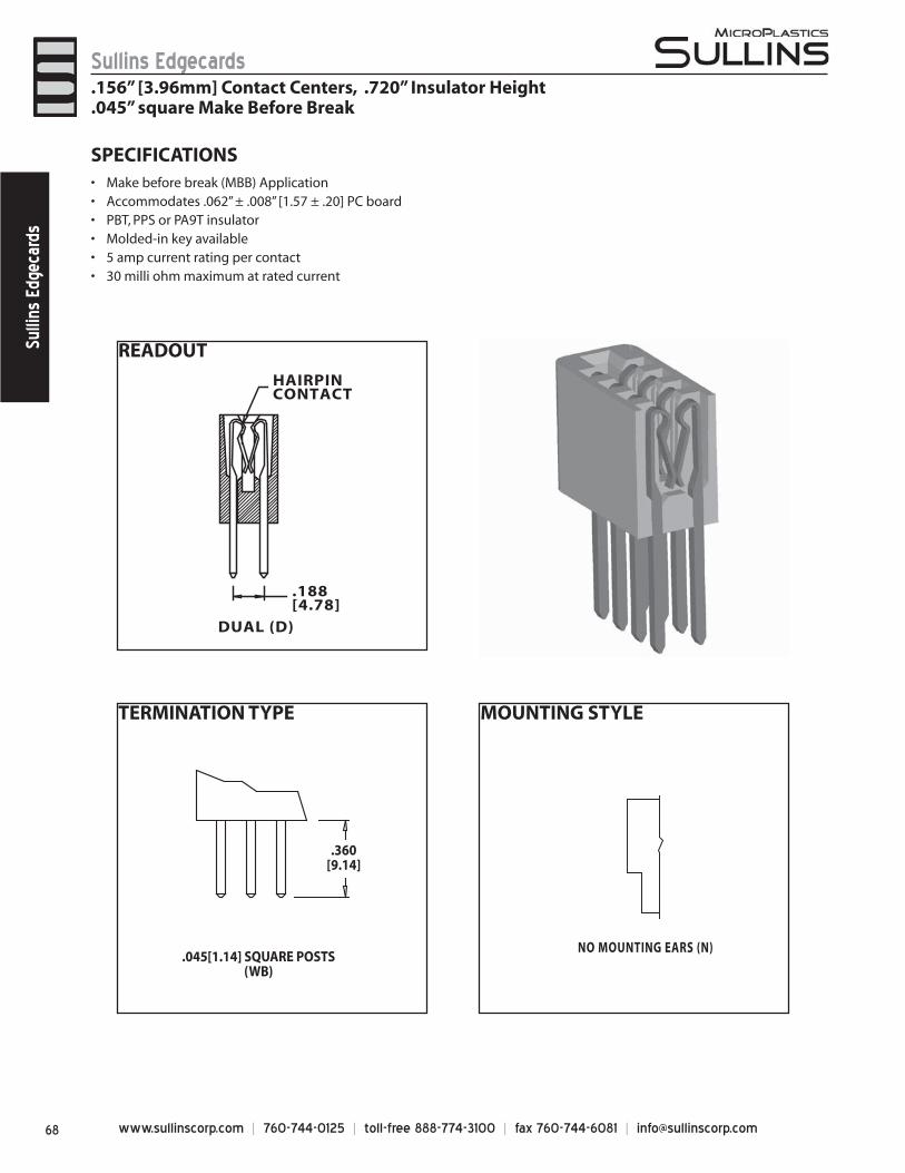
www.sullinscorp.com | 760-744-0125 | toll-free 888-774-3100 | fax 760-744-6081 | [email protected]
Sullins EdgecardsSu
llins
Edg
ecar
ds
READOUT
DUAL (D)
.188[4.78]
HAIRPINCONTACT
TERMINATION TYPE
.045[1.14] SQUARE POSTS(WB)
.360[9.14]
MOUNTING STYLE
NO MOUNTING EARS (N)
SPECIFICATIONSMake b• efore break (MBB) Application Accommodates .062” ± .008” [1.57 ± .20] PC board• PBT, PPS or PA9T insulator• Molded-in key available• 5 amp current rating• per contact30 milli ohm maximum at rated current•
.156” [3.96mm] Contact Centers, .720” Insulator Height
.045” square Make Before Break
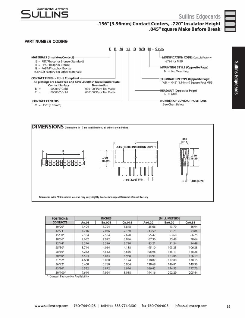
69www.sullinscorp.com | 760-744-0125 | toll-free 888-774-3100 | fax 760-744-6081 | [email protected]
Sullins EdgecardsSullins Edgecards
POSITIONS/CONTACTS
INCHES [MILLIMETERS]A±.08 B±.008 C±.015 A±0.20 B±0.20 C±0.38
10/20* 1.404 1.724 1.848 35.66 43.79 46.9412/24 1.716 2.036 2.160 43.59 51.71 54.8615/30* 2.184 2.504 2.628 55.47 63.60 66.7518/36* 2.652 2.972 3.096 67.36 75.49 78.6422/44* 3.276 3.596 3.720 83.21 91.34 94.4925/50* 3.744 4.064 4.188 95.10 103.23 106.3828/56* 4.212 4.532 4.656 106.98 115.11 118.2630/60* 4.524 4.844 4.968 114.91 123.04 126.1931/62* 4.680 5.000 5.124 118.87 127.00 130.1536/72* 5.460 5.780 5.904 138.68 146.81 149.9643/86* 6.552 6.872 6.996 166.42 174.55 177.7050/100* 7.644 7.964 8.088 194.16 202.29 205.44
* Consult Factory for Availability.
DIMENSIONS Dimensions in [ ] are in millimeters, all others are in inches.
B
.720[18.29]
.515 [13.08] INSERTION DEPTH
.156 [3.96] TYP.
A
.360[9.14]
.720[18.29]
.188 [4.78]
C
Tolerances with PPS Insulator Material may vary slightly due to shrinkage differential; Consult Factory.
PART NUMBER CODING
.156” [3.96mm] Contact Centers, .720” Insulator Height.045” square Make Before Break
MATERIALS (Insulator/Contact)E = PBT/Phosphor Bronze (Standard)R = PPS/Phosphor BronzeG = PA9T/Phosphor Bronze
(Consult Factory For Other Materials)
CONTACT FINISH - RoHS Compliant
CONTACT CENTERSM = .156” [3.96mm]
NUMBER OF CONTACT POSITIONS
READOUT (Opposite Page)D = Dual
MOUNTING STYLE (Opposite Page)
TERMINATION TYPE (Opposite Page)WB = .045” [1.14mm] Square Post MBB
-S796 for MBB
N = No Mounting
MODIFICATION CODE (Consult Factory)
All platings are Lead Free and have .000050” Nickel underplateContact Surface Termination
B = .000010” Gold .000100” Pure Tin, MatteC = .000030” Gold .000100” Pure Tin, Matte
See Chart Below
E B M 12 D WB N - S796
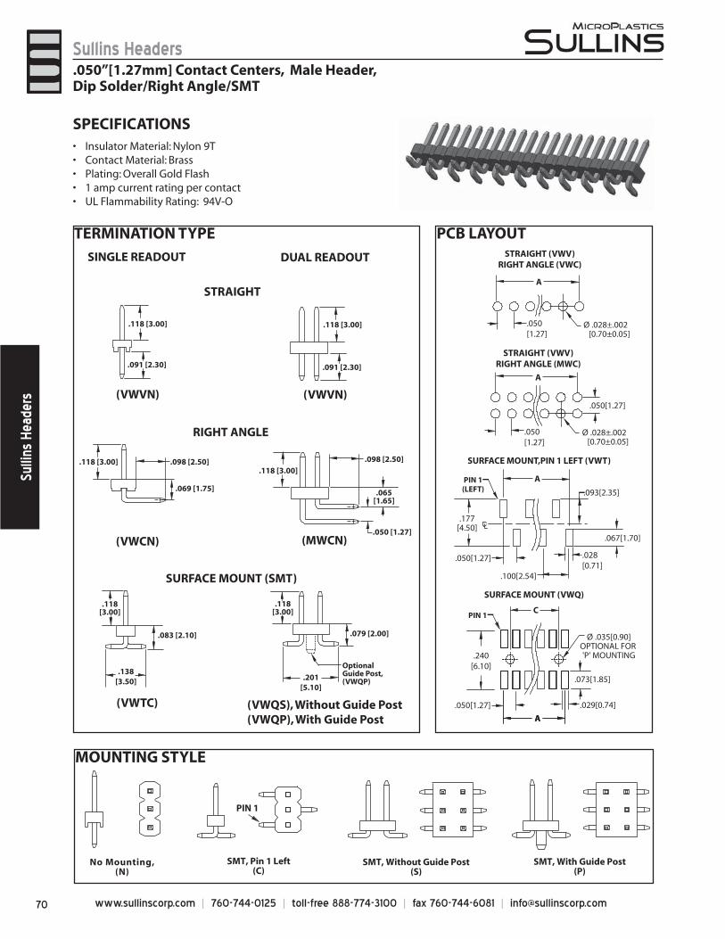
www.sullinscorp.com | 760-744-0125 | toll-free 888-774-3100 | fax 760-744-6081 | [email protected]
Sullins HeadersSu
llins
Hea
ders
TERMINATION TYPE PCB LAYOUT
MOUNTING STYLE
SPECIFICATIONSInsulato• r Material: Nylon 9T Contact Material: Brass • Plating: Overall Gold Flash• 1 amp current rating• per contactUL Flammability Rating: 94V-O•
A
Ø .028±.002 [0.70±0.05]
.050[1.27]
Ø .028±.002 [0.70±0.05]
.050[1.27]
.050[1.27]
A
.050[1.27]
A
.100[2.54]
.093[2.35]
.177[4.50]
.067[1.70]
.028[0.71]
PIN 1(LEFT)
AA
.073[1.85]
.029[0.74].050[1.27]
.240[6.10]
STRAIGHT (VWV)RIGHT ANGLE (VWC)
SURFACE MOUNT,PIN 1 LEFT (VWT)
STRAIGHT (VWV)RIGHT ANGLE (MWC)
SURFACE MOUNT (VWQ)
PIN 1
Ø .035[0.90]OPTIONAL FOR 'P' MOUNTING
C
SINGLE READOUT
(VWVN)
(VWTC)
(VWCN)
.118 [3.00]
.091 [2.30]
.138[3.50]
.098 [2.50]
.118[3.00]
.118 [3.00]
STRAIGHT
RIGHT ANGLE
SURFACE MOUNT (SMT)
DUAL READOUT
(VWVN)
(VWQS), Without Guide Post(VWQP), With Guide Post
(MWCN)
.201[5.10]
.118 [3.00]
.091 [2.30]
.118[3.00]
.098 [2.50].118 [3.00]
.069 [1.75]
.050 [1.27]
.083 [2.10] .079 [2.00]
.065[1.65]
Optional Guide Post, (VWQP)
.050”[1.27mm] Contact Centers, Male Header,Dip Solder/Right Angle/SMT
No Mounting,(N)
SMT, Without Guide Post(S)
PIN 1
SMT, Pin 1 Left(C)
SMT, With Guide Post(P)
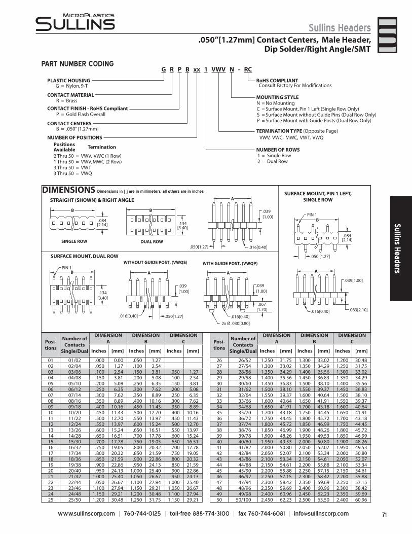
71www.sullinscorp.com | 760-744-0125 | toll-free 888-774-3100 | fax 760-744-6081 | [email protected]
Sullins HeadersSullins Headers
B
.084[2.14] .134
[3.40]
.039[1.00]
.050[1.27] .016[0.40]
.084[2.14]
BPIN 1
.050 [1.27]
A
.039[1.00]
.016[0.40] .083[2.10]
A
.039[1.00]
.050[1.27].016[0.40]
A
.134[3.40]
B
SINGLE ROW DUAL ROW
B
STRAIGHT (SHOWN) & RIGHT ANGLE SURFACE MOUNT, PIN 1 LEFT,
SINGLE ROW
SURFACE MOUNT, DUAL ROW
PIN 1
2x Ø .030[0.80]
.067[1.70]
.039[1.00]
.016[0.40]
A
WITHOUT GUIDE POST, (VWQS) WITH GUIDE POST, (VWQP)
DIMENSIONS Dimensions in [ ] are in millimeters, all others are in inches.
PART NUMBER CODING
.050”[1.27mm] Contact Centers, Male Header,Dip Solder/Right Angle/SMT
1 = Single Row2 = Dual Row
MOUNTING STYLEN = No MountingC = Surface Mount, Pin 1 Left (Single Row Only)S = Surface Mount without Guide Pins (Dual Row Only)P = Surface Mount with Guide Posts (Dual Row Only)
TERMINATION TYPE (Opposite Page)
NUMBER OF ROWS
VWV, VWC, MWC, VWT, VWQ
G = Nylon, 9-T
R = Brass
P = Gold Flash Overall
B = .050” [1.27mm]
PLASTIC HOUSING
CONTACT MATERIAL
CONTACT FINISH - RoHS Compliant
CONTACT CENTERS
NUMBER OF POSITIONSPositionsAvailable Termination
2 Thru 50 = VWV, VWC (1 Row)1 Thru 50 = VWV, MWC (2 Row)3 Thru 50 = VWT3 Thru 50 = VWQ
G R P B xx 1 VWV N - RC
RoHS COMPLIANTConsult Factory For Modifications
Posi-tions
Number of Contacts
Single/Dual
DIMENSION A
DIMENSIONB
DIMENSIONC Posi-
tions
Number of Contacts
Single/Dual
DIMENSION A
DIMENSIONB
DIMENSIONC
Inches [mm] Inches [mm] Inches [mm] Inches [mm] Inches [mm] Inches [mm]
01 01/02 .000 0.00 .050 1.27 26 26/52 1.250 31.75 1.300 33.02 1.200 30.4802 02/04 .050 1.27 .100 2.54 27 27/54 1.300 33.02 1.350 34.29 1.250 31.7503 03/06 .100 2.54 .150 3.81 .050 1.27 28 28/56 1.350 34.29 1.400 25.56 1.300 33.0204 04/08 .150 3.81 .200 5.08 .100 2.54 29 29/58 1.400 35.56 1.450 36.83 1.350 34.2905 05/10 .200 5.08 .250 6.35 .150 3.81 30 30/60 1.450 36.83 1.500 38.10 1.400 35.5606 06/12 .250 6.35 .300 7.62 .200 5.08 31 31/62 1.500 38.10 1.550 39.37 1.450 36.8307 07/14 .300 7.62 .350 8.89 .250 6.35 32 32/64 1.550 39.37 1.600 40.64 1.500 38.1008 08/16 .350 8.89 .400 10.16 .300 7.62 33 33/66 1.600 40.64 1.650 41.91 1.550 39.3709 09/18 .400 10.16 .450 11.43 .350 8.89 34 34/68 1.650 41.91 1.700 43.18 1.600 40.6410 10/20 .450 11.43 .500 12.70 .400 10.16 35 35/70 1.700 43.18 1.750 44.45 1.650 41.9111 11/22 .500 12.70 .550 13.97 .450 11.43 36 36/72 1.750 44.45 1.800 45.72 1.700 43.1812 12/24 .550 13.97 .600 15.24 .500 12.70 37 37/74 1.800 45.72 1.850 46.99 1.750 44.4513 13/26 .600 15.24 .650 16.51 .550 13.97 38 38/76 1.850 46.99 1.900 48.26 1.800 45.7214 14/28 .650 16.51 .700 17.78 .600 15.24 39 39/78 1.900 48.26 1.950 49.53 1.850 46.9915 15/30 .700 17.78 .750 19.05 .650 16.51 40 40/80 1.950 49.53 2.000 50.80 1.900 48.2616 16/32 .750 19.05 .800 20.32 .700 17.78 41 41/82 2.000 50.80 2.050 52.07 1.950 49.5317 17/34 .800 20.32 .850 21.59 .750 19.05 42 42/84 2.050 52.07 2.100 53.34 2.000 50.8018 18/36 .850 21.59 .900 22.86 .800 20.32 43 43/86 2.100 53.34 2.150 54.61 2.050 52.0719 19/38 .900 22.86 .950 24.13 .850 21.59 44 44/88 2.150 54.61 2.200 55.88 2.100 53.3420 20/40 .950 24.13 1.000 25.40 .900 22.86 45 45/90 2.200 55.88 2.250 57.15 2.150 54.6121 21/42 1.000 25.40 1.050 26.67 .950 24.13 46 46/92 2.250 57.15 2.300 58.42 2.200 55.8822 22/44 1.050 26.67 1.100 27.94 1.000 25.40 47 47/94 2.300 58.42 2.350 59.69 2.250 57.1523 23/46 1.100 27.94 1.150 29.21 1.050 26.67 48 48/96 2.350 59.69 2.400 60.96 2.300 58.4224 24/48 1.150 29.21 1.200 30.48 1.100 27.94 49 49/98 2.400 60.96 2.450 62.23 2.350 59.6925 25/50 1.200 30.48 1.250 31.75 1.150 29.21 50 50/100 2.450 62.23 2.500 63.50 2.400 60.96
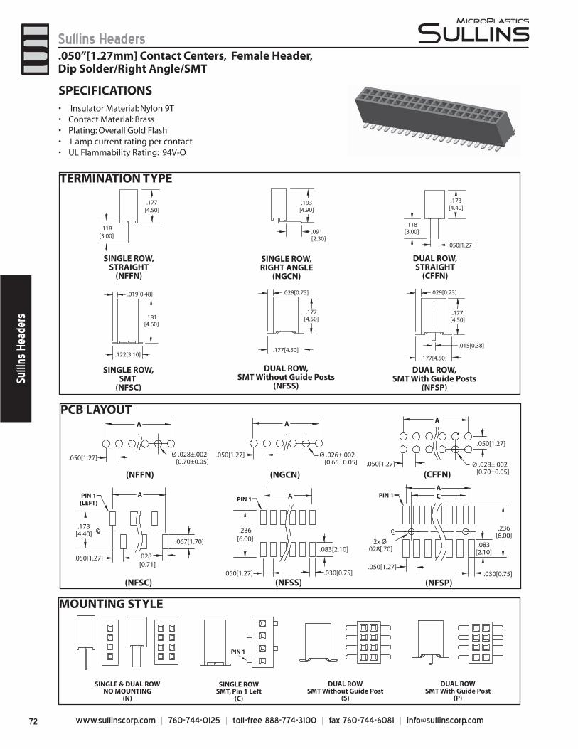
www.sullinscorp.com | 760-744-0125 | toll-free 888-774-3100 | fax 760-744-6081 | [email protected]
Sullins HeadersSu
llins
Hea
ders
TERMINATION TYPE
PCB LAYOUT
MOUNTING STYLE
SPECIFICATIONS Insulator Mater• ial: Nylon 9T Contact Material: Brass • Plating: Overall Gold Flash• 1 amp current rating• per contactUL Flammability Rating: 94V-O•
SINGLE ROW,STRAIGHT
(NFFN)
DUAL ROW,STRAIGHT
(CFFN)
SINGLE ROW,RIGHT ANGLE
(NGCN)
SINGLE ROW,SMT
(NFSC)
DUAL ROW,SMT Without Guide Posts
(NFSS)
DUAL ROW,SMT With Guide Posts
(NFSP)
.118[3.00]
.177[4.50]
.118[3.00]
.050[1.27]
.173[4.40]
.193[4.90]
.091[2.30]
.122[3.10]
.181[4.60]
.177[4.50]
.177[4.50]
.029[0.73] .029[0.73]
.177[4.50]
.177[4.50]
.015[0.38]
.019[0.48]
(NFFN) (CFFN)(NGCN)
(NFSC) (NFSS) (NFSP)
A
Ø .028±.002 [0.70±0.05]
.050[1.27]Ø .028±.002
[0.70±0.05].050[1.27]
.050[1.27]
AA
Ø .026±.002 [0.65±0.05]
.050[1.27]
.050[1.27]
A
.173[4.40]
.067[1.70]
.028[0.71]
PIN 1(LEFT)
A
.083[2.10]
.030[0.75].050[1.27]
.236[6.00]
.050[1.27].030[0.75]
2x Ø.028[.70]
AC
.083[2.10]
.236[6.00]
PIN 1PIN 1
PIN 1
SINGLE & DUAL ROWNO MOUNTING
(N)
SINGLE ROWSMT, Pin 1 Left
(C)
DUAL ROWSMT Without Guide Post
(S)
DUAL ROWSMT With Guide Post
(P)
.050”[1.27mm] Contact Centers, Female Header,Dip Solder/Right Angle/SMT
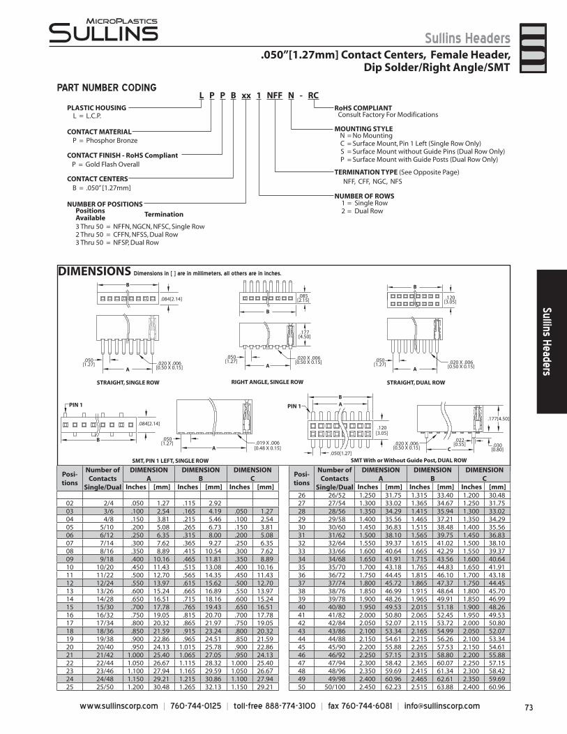
73www.sullinscorp.com | 760-744-0125 | toll-free 888-774-3100 | fax 760-744-6081 | [email protected]
Sullins HeadersSullins Headers
DIMENSIONS Dimensions in [ ] are in millimeters, all others are in inches.
PART NUMBER CODING
.050”[1.27mm] Contact Centers, Female Header,Dip Solder/Right Angle/SMT
Posi-tions
Number of Contacts
Single/Dual
DIMENSION A
DIMENSIONB
DIMENSIONC
Posi-tions
Number of Contacts
Single/Dual
DIMENSION A
DIMENSIONB
DIMENSIONC
Inches [mm] Inches [mm] Inches [mm] Inches [mm] Inches [mm] Inches [mm]26 26/52 1.250 31.75 1.315 33.40 1.200 30.48
02 2/4 .050 1.27 .115 2.92 27 27/54 1.300 33.02 1.365 34.67 1.250 31.7503 3/6 .100 2.54 .165 4.19 .050 1.27 28 28/56 1.350 34.29 1.415 35.94 1.300 33.0204 4/8 .150 3.81 .215 5.46 .100 2.54 29 29/58 1.400 35.56 1.465 37.21 1.350 34.2905 5/10 .200 5.08 .265 6.73 .150 3.81 30 30/60 1.450 36.83 1.515 38.48 1.400 35.5606 6/12 .250 6.35 .315 8.00 .200 5.08 31 31/62 1.500 38.10 1.565 39.75 1.450 36.8307 7/14 .300 7.62 .365 9.27 .250 6.35 32 32/64 1.550 39.37 1.615 41.02 1.500 38.1008 8/16 .350 8.89 .415 10.54 .300 7.62 33 33/66 1.600 40.64 1.665 42.29 1.550 39.3709 9/18 .400 10.16 .465 11.81 .350 8.89 34 34/68 1.650 41.91 1.715 43.56 1.600 40.6410 10/20 .450 11.43 .515 13.08 .400 10.16 35 35/70 1.700 43.18 1.765 44.83 1.650 41.9111 11/22 .500 12.70 .565 14.35 .450 11.43 36 36/72 1.750 44.45 1.815 46.10 1.700 43.1812 12/24 .550 13.97 .615 15.62 .500 12.70 37 37/74 1.800 45.72 1.865 47.37 1.750 44.4513 13/26 .600 15.24 .665 16.89 .550 13.97 38 38/76 1.850 46.99 1.915 48.64 1.800 45.7014 14/28 .650 16.51 .715 18.16 .600 15.24 39 39/78 1.900 48.26 1.965 49.91 1.850 46.9915 15/30 .700 17.78 .765 19.43 .650 16.51 40 40/80 1.950 49.53 2.015 51.18 1.900 48.2616 16/32 .750 19.05 .815 20.70 .700 17.78 41 41/82 2.000 50.80 2.065 52.45 1.950 49.5317 17/34 .800 20.32 .865 21.97 .750 19.05 42 42/84 2.050 52.07 2.115 53.72 2.000 50.8018 18/36 .850 21.59 .915 23.24 .800 20.32 43 43/86 2.100 53.34 2.165 54.99 2.050 52.0719 19/38 .900 22.86 .965 24.51 .850 21.59 44 44/88 2.150 54.61 2.215 56.26 2.100 53.3420 20/40 .950 24.13 1.015 25.78 .900 22.86 45 45/90 2.200 55.88 2.265 57.53 2.150 54.6121 21/42 1.000 25.40 1.065 27.05 .950 24.13 46 46/92 2.250 57.15 2.315 58.80 2.200 55.8822 22/44 1.050 26.67 1.115 28.32 1.000 25.40 47 47/94 2.300 58.42 2.365 60.07 2.250 57.1523 23/46 1.100 27.94 1.165 29.59 1.050 26.67 48 48/96 2.350 59.69 2.415 61.34 2.300 58.4224 24/48 1.150 29.21 1.215 30.86 1.100 27.94 49 49/98 2.400 60.96 2.465 62.61 2.350 59.6925 25/50 1.200 30.48 1.265 32.13 1.150 29.21 50 50/100 2.450 62.23 2.515 63.88 2.400 60.96
P = Gold Flash Overall
PLASTIC HOUSINGL = L.C.P.
CONTACT MATERIALP = Phosphor Bronze
CONTACT FINISH - RoHS Compliant
CONTACT CENTERSB = .050” [1.27mm]
1 = Single Row2 = Dual Row
MOUNTING STYLE
TERMINATION TYPE (See Opposite Page)
NUMBER OF ROWS
NFF, CFF, NGC, NFS
NUMBER OF POSITIONS
L P P B xx 1 NFF N - RCRoHS COMPLIANT
Consult Factory For Modifications
N = No MountingC = Surface Mount, Pin 1 Left (Single Row Only)S = Surface Mount without Guide Pins (Dual Row Only)P = Surface Mount with Guide Posts (Dual Row Only)
PositionsAvailable Termination
3 Thru 50 = NFFN, NGCN, NFSC, Single Row2 Thru 50 = CFFN, NFSS, Dual Row3 Thru 50 = NFSP, Dual Row
STRAIGHT, SINGLE ROW
B
.084[2.14]
.050[1.27]
A.020 X .006
[0.50 X 0.15]
.120[3.05]
.020 X .006[0.50 X 0.15]
.050[1.27]
.050[1.27]
B
A
STRAIGHT, DUAL ROW
.020 X .006[0.50 X 0.15]
B
.085[2.15]
.177[4.50]
A
RIGHT ANGLE, SINGLE ROW
PIN 1
B
.084[2.14]
.050[1.27]
A.019 X .006
[0.48 X 0.15]
SMT, PIN 1 LEFT, SINGLE ROW.050[1.27]
.020 X .006[0.50 X 0.15]
A
.120[3.05]
B
C
.022[0.55]
.177[4.50]
.030[0.80]
SMT With or Without Guide Post, DUAL ROW
PIN 1
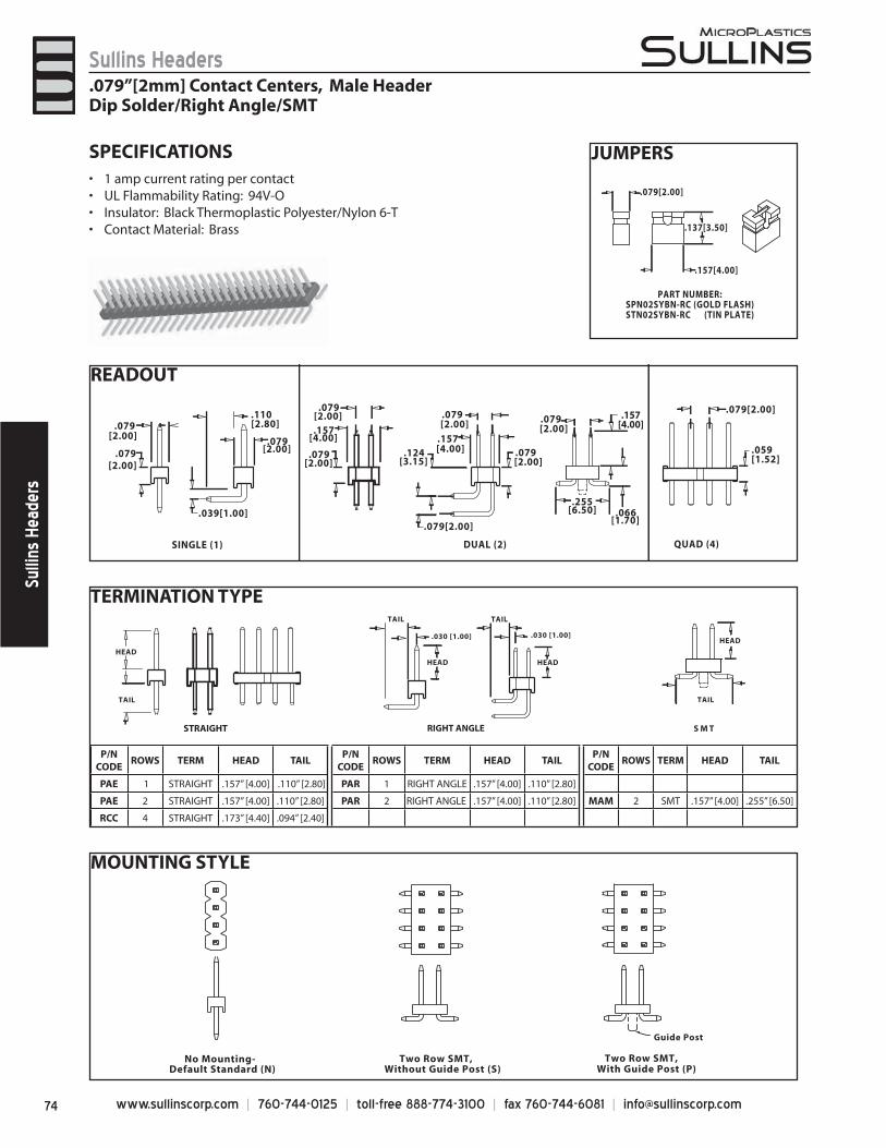
www.sullinscorp.com | 760-744-0125 | toll-free 888-774-3100 | fax 760-744-6081 | [email protected]
Sullins HeadersSu
llins
Hea
ders
READOUT
TERMINATION TYPE
MOUNTING STYLE
Two Row SMT,With Guide Post (P)
No Mounting-Default Standard (N)
Two Row SMT, Without Guide Post (S)
Guide Post
SINGLE (1) DUAL (2)
[2.00].079
[2.00].079
[2.00] .079
.039[1.00]
[2.00].079
[2.00].079
[4.00].157
[4.00].157
[2.00].079
[2.00].079
[3.15].124
.079[2.00]
[2.80].110
QUAD (4)
.059[1.52]
.079[2.00]
[2.00].079
[6.50].255
[1.70].066
.157[4.00]
HEAD
TAIL
.030 [1.00]
HEAD
TAIL
.030 [1.00]
RIGHT ANGLESTRAIGHT S M T
TAIL
HEAD
TAIL
HEAD
JUMPERSSPECIFICATIONS1 amp c• urrent rating per contactUL Flammability Rating: 94V-O• Insulator: Black Thermoplastic Polyester/Nylon 6-T• Contact Material: Brass•
P/N CODE
ROWS TERM HEAD TAILP/N
CODEROWS TERM HEAD TAIL
P/N CODE
ROWS TERM HEAD TAIL
PAE 1 STRAIGHT .157” [4.00] .110” [2.80] PAR 1 RIGHT ANGLE .157” [4.00] .110” [2.80]
PAE 2 STRAIGHT .157” [4.00] .110” [2.80] PAR 2 RIGHT ANGLE .157” [4.00] .110” [2.80] MAM 2 SMT .157” [4.00] .255” [6.50]
RCC 4 STRAIGHT .173” [4.40] .094” [2.40]
.079”[2mm] Contact Centers, Male HeaderDip Solder/Right Angle/SMT
PART NUMBER:SPN02SYBN-RC (GOLD FLASH)STN02SYBN-RC (TIN PLATE)
.157[4.00]
.079[2.00]
.137[3.50]
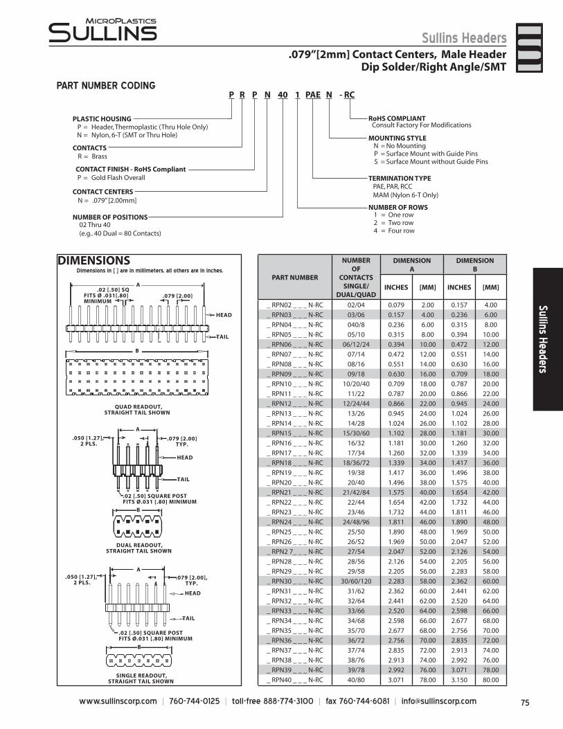
75www.sullinscorp.com | 760-744-0125 | toll-free 888-774-3100 | fax 760-744-6081 | [email protected]
Sullins HeadersSullins Headers
.079”[2mm] Contact Centers, Male HeaderDip Solder/Right Angle/SMT
DIMENSIONSPART NUMBER
NUMBEROF
CONTACTSSINGLE/
DUAL/QUAD
DIMENSIONA
DIMENSIONB
INCHES [MM] INCHES [MM]
_ RPN02 _ _ _ N-RC 02/04 0.079 2.00 0.157 4.00
_ RPN03 _ _ _ N-RC 03/06 0.157 4.00 0.236 6.00
_ RPN04 _ _ _ N-RC 040/8 0.236 6.00 0.315 8.00
_ RPN05 _ _ _ N-RC 05/10 0.315 8.00 0.394 10.00
_ RPN06 _ _ _ N-RC 06/12/24 0.394 10.00 0.472 12.00
_ RPN07 _ _ _ N-RC 07/14 0.472 12.00 0.551 14.00
_ RPN08 _ _ _ N-RC 08/16 0.551 14.00 0.630 16.00
_ RPN09 _ _ _ N-RC 09/18 0.630 16.00 0.709 18.00
_ RPN10 _ _ _ N-RC 10/20/40 0.709 18.00 0.787 20.00
_ RPN11 _ _ _ N-RC 11/22 0.787 20.00 0.866 22.00
_ RPN12 _ _ _ N-RC 12/24/44 0.866 22.00 0.945 24.00
_ RPN13 _ _ _ N-RC 13/26 0.945 24.00 1.024 26.00
_ RPN14 _ _ _ N-RC 14/28 1.024 26.00 1.102 28.00
_ RPN15 _ _ _ N-RC 15/30/60 1.102 28.00 1.181 30.00
_ RPN16 _ _ _ N-RC 16/32 1.181 30.00 1.260 32.00
_ RPN17 _ _ _ N-RC 17/34 1.260 32.00 1.339 34.00
_ RPN18 _ _ _ N-RC 18/36/72 1.339 34.00 1.417 36.00
_ RPN19 _ _ _ N-RC 19/38 1.417 36.00 1.496 38.00
_ RPN20 _ _ _ N-RC 20/40 1.496 38.00 1.575 40.00
_ RPN21 _ _ _ N-RC 21/42/84 1.575 40.00 1.654 42.00
_ RPN22 _ _ _ N-RC 22/44 1.654 42.00 1.732 44.00
_ RPN23 _ _ _ N-RC 23/46 1.732 44.00 1.811 46.00
_ RPN24 _ _ _ N-RC 24/48/96 1.811 46.00 1.890 48.00
_ RPN25 _ _ _ N-RC 25/50 1.890 48.00 1.969 50.00
_ RPN26 _ _ _ N-RC 26/52 1.969 50.00 2.047 52.00
_ RPN2 7_ _ _ N-RC 27/54 2.047 52.00 2.126 54.00
_ RPN28 _ _ _ N-RC 28/56 2.126 54.00 2.205 56.00
_ RPN29 _ _ _ N-RC 29/58 2.205 56.00 2.283 58.00
_ RPN30 _ _ _ N-RC 30/60/120 2.283 58.00 2.362 60.00
_ RPN31 _ _ _ N-RC 31/62 2.362 60.00 2.441 62.00
_ RPN32 _ _ _ N-RC 32/64 2.441 62.00 2.520 64.00
_ RPN33 _ _ _ N-RC 33/66 2.520 64.00 2.598 66.00
_ RPN34 _ _ _ N-RC 34/68 2.598 66.00 2.677 68.00
_ RPN35 _ _ _ N-RC 35/70 2.677 68.00 2.756 70.00
_ RPN36 _ _ _ N-RC 36/72 2.756 70.00 2.835 72.00
_ RPN37 _ _ _ N-RC 37/74 2.835 72.00 2.913 74.00
_ RPN38 _ _ _ N-RC 38/76 2.913 74.00 2.992 76.00
_ RPN39 _ _ _ N-RC 39/78 2.992 76.00 3.071 78.00
_ RPN40 _ _ _ N-RC 40/80 3.071 78.00 3.150 80.00
B
.079 [2.00] .02 [.50] SQFITS Ø .031[.80] MINIMUM
HEAD
TAIL
HEAD
TAIL
SINGLE READOUT, STRAIGHT TAIL SHOWN
B
.02 [.50] SQUARE POSTFITS Ø.031 [.80] MINIMUM
.050 [1.27], 2 PLS.
.079 [2.00],TYP.
QUAD READOUT,STRAIGHT TAIL SHOWN
DUAL READOUT, STRAIGHT TAIL SHOWN
B
.02 [.50] SQUARE POSTFITS Ø.031 [.80] MINIMUM
HEAD
TAIL
.050 [1.27], 2 PLS.
.079 [2.00]TYP.
A
A
A
PART NUMBER CODING
P = Gold Flash OverallCONTACT FINISH - RoHS Compliant
CONTACT CENTERS
NUMBER OF POSITIONS 1 = One row2 = Two row4 = Four row
RoHS COMPLIANT
MOUNTING STYLE
Consult Factory For Modifications
N = No MountingP = Surface Mount with Guide PinsS = Surface Mount without Guide Pins
TERMINATION TYPE
02 Thru 40(e.g.. 40 Dual = 80 Contacts)
NUMBER OF ROWS
PAE, PAR, RCC MAM (Nylon 6-T Only)
N = .079” [2.00mm]
PLASTIC HOUSING
CONTACTSR = Brass
P = Header, Thermoplastic (Thru Hole Only)N = Nylon, 6-T (SMT or Thru Hole)
Dimensions in [ ] are in millimeters, all others are in inches.
P R P N 40 1 PAE N - RC
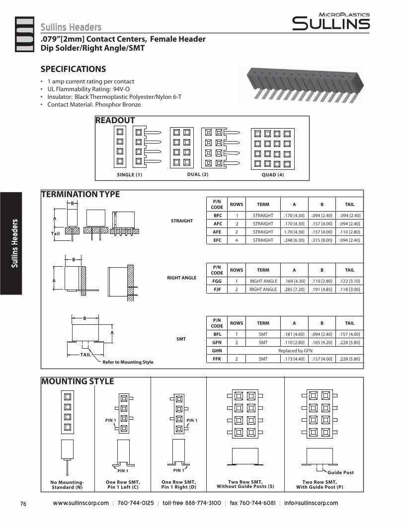
www.sullinscorp.com | 760-744-0125 | toll-free 888-774-3100 | fax 760-744-6081 | [email protected]
Sullins HeadersSu
llins
Hea
ders
MOUNTING STYLE
Guide Post
One Row SMT,Pin 1 Right (D)
One Row SMT,Pin 1 Left (C)
Two Row SMT,With Guide Post (P)
No Mounting-Standard (N)
Two Row SMT,Without Guide Posts (S)
PIN 1 PIN 1
PIN 1PIN 1
READOUT
SINGLE (1) DUAL (2) QUAD (4)
SPECIFICATIONS1 amp current rating• per contactUL Flammability Rating: 94V-O• Insulator: Black Thermoplastic Polyester/Nylon 6-T • Contact Material: Phosphor Bronze•
TERMINATION TYPE
A
Tail
TAIL
A
B
A
B
B
Refer to Mounting Style
RIGHT ANGLE
STRAIGHT
SMT
P/N CODE
ROWS TERM A B TAIL
BFL 1 SMT .181 [4.60] .094 [2.40] .157 [4.00]
GFN 2 SMT .110 [2.80] .165 [4.20] .228 [5.80]
GHN Replaced by GFN
FFK 2 SMT .173 [4.40] .157 [4.00] .228 [5.80]
P/N CODE
ROWS TERM A B TAIL
FGG 1 RIGHT ANGLE .169 [4.30] .110 [2.80] .122 [3.10]
FJF 2 RIGHT ANGLE .285 [7.20] .191 [4.85] .118 [3.00]
P/N CODE
ROWS TERM A B TAIL
BFC 1 STRAIGHT .170 [4.30] .094 [2.40] .094 [2.40]
AFC 2 STRAIGHT .170 [4.30] .157 [4.00] .094 [2.40]
AFE 2 STRAIGHT 1.70 [4.30] .157 [4.00] .110 [2.80]
EFC 4 STRAIGHT .248 [6.30] .315 [8.00] .094 [2.40]
.079”[2mm] Contact Centers, Female HeaderDip Solder/Right Angle/SMT
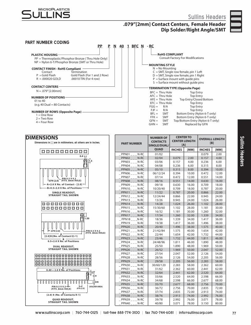
77www.sullinscorp.com | 760-744-0125 | toll-free 888-774-3100 | fax 760-744-6081 | [email protected]
Sullins HeadersSullins Headers
DIMENSIONSPART NUMBER
NUMBER OF CONTACTS
SINGLE/DUAL/QUAD
CENTER TO CENTER LENGTH
[A]
OVERALL LENGTH [B]
INCHES [MM] INCHES [MM]
_ PPN01 _ _ _ N-RC 01/02 0.079 2.00_ PPN02 _ _ _ N-RC 02/04 0.079 2.00 0.157 4.00_ PPN03 _ _ _ N-RC 03/06 0.157 4.00 0.236 6.00_ PPN04 _ _ _ N-RC 04/08 0.236 6.00 0.315 8.00_ PPN05 _ _ _ N-RC 05/10 0.315 8.00 0.394 10.00_ PPN06 _ _ _ N-RC 06/12/24 0.394 10.00 0.472 12.00_ PPN07 _ _ _ N-RC 07/14 0.472 12.00 0.551 14.00_ PPN08 _ _ _ N-RC 08/16 0.551 14.00 0.630 16.00_ PPN09 _ _ _ N-RC 09/18 0.630 16.00 0.709 18.00_ PPN10_ _ _ N-RC 10/20/40 0.709 18.00 0.787 20.00_ PPN11 _ _ _ N-RC 11/22 0.787 20.00 0.866 22.00_ PPN12 _ _ _ N-RC 12/24/44 0.866 22.00 0.945 24.00_ PPN13 _ _ _ N-RC 13/26 0.945 24.00 1.024 26.00_ PPN14 _ _ _ N-RC 14/28 1.024 26.00 1.102 28.00_ PPN15 _ _ _ N-RC 15/30/60 1.102 28.00 1.181 30.00_ PPN16 _ _ _ N-RC 16/32 1.181 30.00 1.260 32.00_ PPN17 _ _ _ N-RC 17/34 1.260 32.00 1.339 34.00_ PPN18 _ _ _N-RC 18/36 1.339 34.00 1.417 36.00_ PPN19 _ _ _ N-RC 19/38 1.417 36.00 1.496 38.00_ PPN20 _ _ _ N-RC 20/40 1.496 38.00 1.575 40.00_ PPN21 _ _ _ N-RC 21/42/84 1.575 40.00 1.654 42.00_ PPN22 _ _ _ N-RC 22/44 1.654 42.00 1.732 44.00_ PPN23 _ _ _ N-RC 23/46 1.732 44.00 1.811 46.00_ PPN24 _ _ _ N-RC 24/48/96 1.811 46.00 1.890 48.00_ PPN25 _ _ _ N-RC 25/50 1.890 48.00 1.969 50.00_ PPN26 _ _ _ N-RC 26/52 1.969 50.00 2.047 52.00_ PPN27 _ _ _ N-RC 27/54 2.047 52.00 2.126 54.00_ PPN28 _ _ _ N-RC 28/56 2.126 54.00 2.205 56.00_ PPN29 _ _ _ N-RC 29/58 2.205 56.00 2.283 58.00_ PPN30 _ _ _ N-RC 30/60/120 2.283 58.00 2.362 60.00_ PPN31 _ _ _ N-RC 31/62 2.362 60.00 2.441 62.00_ PPN32 _ _ _ N-RC 32/64 2.441 62.00 2.520 64.00_ PPN33 _ _ _ N-RC 33/66 2.520 64.00 2.598 66.00_ PPN34 _ _ _ N-RC 34/68 2.598 66.00 2.677 68.00_ PPN35 _ _ _ N-RC 35/70 2.677 68.00 2.756 70.00_ PPN36 _ _ _ N-RC 36/72 2.756 70.00 2.835 72.00_ PPN37 _ _ _ N-RC 37/74 2.835 72.00 2.913 74.00_ PPN38 _ _ _ N-RC 38/76 2.913 74.00 2.992 76.00_ PPN39 _ _ _ N-RC 39/78 2.992 76.00 3.071 78.00_ PPN40 _ _ _ N-RC 40/80 3.071 78.00 3.150 80.00
SINGLE READOUT,STRAIGHT TAIL SHOWN
A=2.0 X No. of Contact - [2.0]
.079 [2.0] PIN 0.5 X 0.2(FITS .8mm HOLE)
B=0.5+2.0 X No. of Positions
0.4
1.5
DUAL READOUT,STRAIGHT TAIL SHOWN
.079 [2.0]
B0.5+2.0 X No. of Positions
A[2.0]X((No. of Contact/2)-1)
1.50
QUAD READOUT,STRAIGHT TAIL SHOWN
.079 [2.0]
B 0.40 + 2.0 X No. of Positions
A [2.0] X (No. of Contacts/4-1)
1.92
6.30
2.40(B)
(SOLDER AREA)
PIN 0.5 X 0.2(FITS .8mm HOLE)
PIN 0.5 X 0.2(FITS .8mm HOLE)
PART NUMBER CODING
.079”[2mm] Contact Centers, Female HeaderDip Solder/Right Angle/SMT
PLASTIC HOUSINGPP = Thermoplastic/Phosphor Bronze ( Thru Hole Only)NP = Nylon 6-T/Phosphor Bronze (SMT or Thru Hole)
Contact TerminationP = Gold Flash Gold Flash (For 1 and 2 Row)R = .000020 GOLD .00010 TIN (For 4 row)
CONTACT FINISH - RoHS Compliant
CONTACT CENTERSN = .079” [2.00mm]
NUMBER OF POSITIONS
1 = One Row2 = Two Row4 = Four Row
RoHS COMPLIANT
MOUNTING STYLE
Consult Factory For Modifications
N = No MountingC = SMT, Single row female, pin 1 LeftD = SMT, Single row female, pin 1 RightP = Surface mount with guide pinsS = Surface mount without guide pins
TERMINATION TYPE (Opposite Page)
01 to 40(e.g. 40 Dual = 80 Contacts)
NUMBER OF ROWS (Opposite Page)
BFC = Thru Hole Top EntryAFC = Thru Hole Top EntryAFE = Thru Hole Top Entry/Closed BottomEFC = Thru Hole Top Entry
FGG = R/A Top EntryFJF = R/A Top EntryBFL = SMT Bottom Entry (Nylon 6-T only)FFK = SMT Bottom Entry (Nylon 6-T only)
GFN = SMT Top/Bottom Entry (Nylon 6-T only)GHN = SMT Replaced by GFN
PP P N 40 1 BFC N - RC
Dimensions in [ ] are in millimeters, all others are in inches.
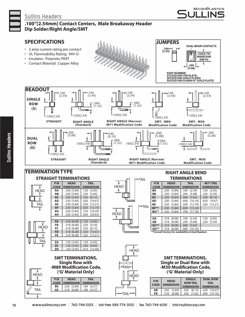
www.sullinscorp.com | 760-744-0125 | toll-free 888-774-3100 | fax 760-744-6081 | [email protected]
Sullins HeadersSu
llins
Hea
ders
TERMINATION TYPE
JUMPERSSPECIFICATIONS3 am• p current rating per contactUL Flammability Rating: 94V-O• Insulator: Polyester, PA9T• Contact Material: Copper Alloy•
PART NUMBER:STC02SYAN (TIN PLATE)SPC02SYAN (GOLD FLASH)SSC02SYAN (0.000010" GOLD PLATE)
.226[5.74]INSERTION
DEPTH
.200[5.08]
.100[2.54]
DUAL BEAM CONTACTS
.100”[2.54mm] Contact Centers, Male Breakaway HeaderDip Solder/Right Angle/SMT
READOUT
SINGLE ROW
(S)
DUALROW
(D)
.100[2.54]
.100[2.54]
.140[3.56]
.060[1.52]
.200[5.08]
.100[2.54]
.240[6.10]
.060[1.52]
.200[5.08]
.100[2.54]
.060[1.52]
.140[3.56]
.060[1.52].100[2.54]
.200[5.08]
.100[2.54]
.100[2.54]
RIGHT ANGLE (Narrow)-M71 Modification Code
RIGHT ANGLE(Standard)
SMT, -M89Modification Code
STRAIGHT SMT, -M30Modification Code
.100[2.54] .100[2.54].100[2.54]
.100[2.54]
SMT, -M30Modification Code
RIGHT ANGLE (Narrow)-M71 Modification Code
RIGHT ANGLE(Standard)
STRAIGHT
.100[2.54]
HEAD
TAIL
HEAD
TAIL
P/NCODE
HEAD DIMENSION
TAIL DIMENSION
AA .230 [5.84] .120 [3.05]AB .230 [5.84] .230 [5.84]AC .230 [5.84] .320 [8.13]AD .230 [5.84] .420 [10.67]AE .230 [5.84] .520 [13.21]AF .230 [5.84] .620 [15.75]AG .230 [5.84] .720 [18.29]AH .230 [5.84] .820 [20.83]
FA .318 [8.08] .120 [3.05]FB .318 [8.08] .220 [5.59]FC .318 [8.08] .320 [8.13]FD .318 [8.08] .420 [10.67]FE .318 [8.08] .520 [13.21]
ZA .120 [3.05] .120 [3.05]ZC .120 [3.05] .260 [6.60]ZD .120 [3.05] .610 [15.49]
STRAIGHT TERMINATIONSP/N
CODEHEAD
DIMENSIONTAIL
DIMENSION-M71 TAIL
DIMENSIONBA .230 [5.84] .100 [2.54] .120 [3.05]BB .230 [5.84] .200 [5.08] .220 [5.59]BC .230 [5.84] .300 [7.62] .320 [8.13]BD .230 [5.84] .400 [10.16] .420 10.67]BE .230 [5.84] .500 [12.70] .520 [12.21]BF** .230 [5.84] .600 [15.24]BG** .230 [5.84] .700 [17.78]
GA .318 [8.08] .100 [2.54] .120 [3.05]GB .318 [8.08] .200 [5.08] .220 [5.59]GC** .318 [8.08] .300 [7.62]GD** .318 [8.08] .400 [10.16]
**Consult Factory for availability in Dual Readout.
HEAD
HEAD
TAIL
TAIL
RIGHT ANGLE BEND TERMINATIONS
P/N CODE
HEADDIMENSION
SINGLE ROW TAIL
DIMENSION
DUAL ROW TAIL
DIMENSIONAB .230 [5.84] .320 [8.13] .420 [10.67]FB .318 [8.08] .300 [7.62] .400 [10.16]
SMT TERMINATIONS, Single or Dual Row with -M30 Modifi cation Code,
(‘G’ Material Only)HEAD
TAIL
TAIL
HEAD
P/N CODE
HEAD DIMENSION
TAIL DIMENSION
BS .230 [5.84] .180 [4.57]GS .318 [8.08] .180 [4.57]
SMT TERMINATIONS, Single Row with
-M89 Modifi cation Code,(‘G’ Material Only)
HEAD
TAIL
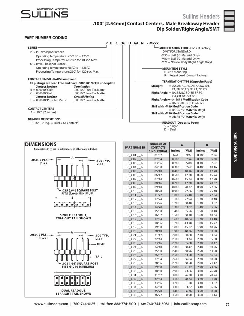
79www.sullinscorp.com | 760-744-0125 | toll-free 888-774-3100 | fax 760-744-6081 | [email protected]
Sullins HeadersSullins Headers
DIMENSIONSPART NUMBER
NUMBER OF CONTACTS
SINGLE/DUAL
A B
Inches [MM] Inches [MM]
P _ C01 _ _ N 01/02 N/A N/A 0.100 2.54P _ C02 _ _ N 02/04 0.100 2.54 0.200 5.08P _ C03 _ _ N 03/06 0.200 5.08 0.300 7.62P _ C04 _ _ N 04/08 0.300 7.62 0.400 10.16P _ C05 _ _ N 05/10 0.400 10.16 0.500 12.70P _ C06 _ _ N 06/12 0.500 12.70 0.600 15.24P _ C07 _ _ N 07/14 0.600 15.24 0.700 17.78P _ C08 _ _ N 08/16 0.700 17.78 0.800 20.32P _ C09 _ _ N 09/18 0.800 20.32 0.900 22.86P _ C10 _ _ N 10/20 0.900 22.86 1.000 25.40P _ C11 _ _ N 11/22 1.000 25.40 1.100 27.94P _ C12 _ _ N 12/24 1.100 27.94 1.200 30.48P _ C13 _ _ N 13/26 1.200 30.48 1.300 33.02P _ C14 _ _ N 14/28 1.300 33.02 1.400 35.56P _ C15 _ _ N 15/30 1.400 35.56 1.500 38.10P _ C16 _ _ N 16/32 1.500 38.10 1.600 40.64P _ C17 _ _ N 17/34 1.600 40.64 1.700 43.18P _ C18 _ _ N 18/36 1.700 43.18 1.800 45.72P _ C19 _ _ N 19/38 1.800 45.72 1.900 48.26P _ C20 _ _ N 20/40 1.900 48.26 2.000 50.80P _ C21 _ _ N 21/42 2.000 50.80 2.100 53.34P _ C22 _ _ N 22/44 2.100 53.34 2.200 55.88P _ C23 _ _ N 23/46 2.200 55.88 2.300 58.42P _ C24 _ _ N 24/48 2.300 58.42 2.400 60.96P _ C25 _ _ N 25/50 2.400 60.96 2.500 63.50P _ C26 _ _ N 26/52 2.500 63.50 2.600 66.04P _ C27 _ _ N 27/54 2.600 66.04 2.700 68.58P _ C28 _ _ N 28/56 2.700 68.58 2.800 71.12P _ C29 _ _ N 29/58 2.800 71.12 2.900 73.66P _ C30 _ _ N 30/60 2.900 73.66 3.000 76.20P _ C31 _ _ N 31/62 3.000 76.20 3.100 78.74P _ C32 _ _ N 32/64 3.100 78.74 3.200 81.28P _ C33 _ _ N 33/66 3.200 81.28 3.300 83.82P _ C34 _ _ N 34/68 3.300 83.82 3.400 86.36P _ C35 _ _ N 35/70 3.400 86.36 3.500 88.90P _ C36 _ _ N 36/72 3.500 88.90 3.600 91.44
HEAD
TAIL
SINGLE READOUT,STRAIGHT TAIL SHOWN
DUAL READOUT,STRAIGHT TAIL SHOWN
B
B
.025 [.64] SQUARE POSTFITS Ø.040 MINIMUM
.050, 2 PLS.[1.27]
.100 TYP.[2.54]
.050, 2 PLS.[1.27]
.100 TYP.[2.54]
.025 [.64] SQUARE POSTFITS Ø.040 MINIMUM
A
A
PART NUMBER CODING
.100”[2.54mm] Contact Centers, Male Breakaway HeaderDip Solder/Right Angle/SMT
SERIESP = PBT/Phosphor Bronze
Operating Temperature: -65°C to + 125°CProcessing Temperature: 260° for 10 sec. Max.
G = PA9T/Phosphor BronzeOperating Temperature: -65°C to + 125°CProcessing Temperature: 260° for 120 sec. Max.
CONTACT FINISH - RoHS CompliantAll platings are Lead Free and have .000050” Nickel underplate
Contact Surface TerminationB = .000010” Gold .000100” Pure Tin, Matte C = .000030” Gold .000100” Pure Tin, Matte
Contact Surface Overall PlatingE = .000010” Pure Tin, Matte .000100” Pure Tin, Matte
CONTACT CENTERSC = .100” [2.54mm]
NUMBER OF POSITIONS
S = SingleD = Dual
MOUNTING STYLEN =No MountingR =Retent Lead (Consult Factory)
TERMINATION TYPE (Opposite Page)
01 Thru 36 (eg. 32 Dual = 64 Contacts) READOUT (Opposite Page)
MODIFICATION CODE (Consult Factory) OMIT FOR STANDARD
P B C 36 D AA N - Mxxx
Dimensions in [ ] are in millimeters, all others are in inches.
-M30 = SMT (‘G’ Material Only)-M89 = SMT (‘G’ Material Only)-M71 = Narrow Body (Right Angle Only)
Straight = AA, AB, AC, AD, AE, AF, AG, AH,FA, FB, FC, FD, FE, ZA, ZC, ZD
Right Angle = BA, BB, BC, BD, BE, BF, BG,GA, GB, GC, GD, GS
Right Angle with -M71 Modifi cation Code= BA, BB, BC, BD, BE, GA, GB
SMT with -M89 Modifi cation Code= BS, GS (‘G’ Material Only)
SMT with -M30 Modifi cation Code= AB, FB (‘G’ Material Only)
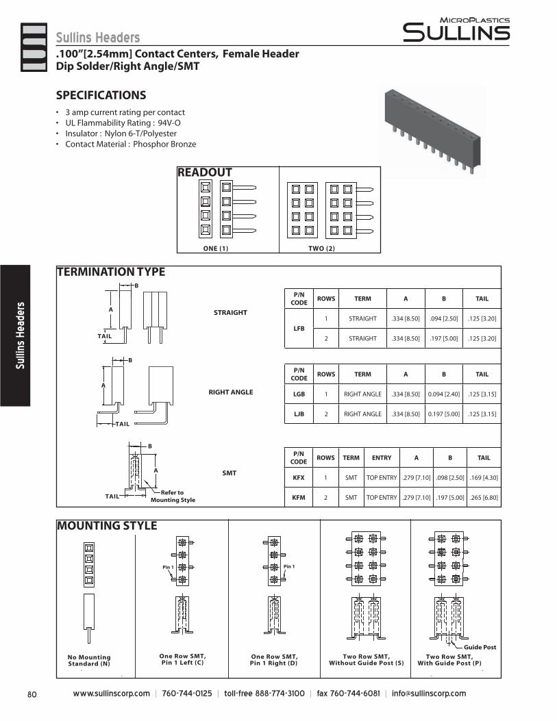
www.sullinscorp.com | 760-744-0125 | toll-free 888-774-3100 | fax 760-744-6081 | [email protected]
Sullins HeadersSu
llins
Hea
ders
READOUT
MOUNTING STYLE
ONE (1) TWO (2)
One Row SMT,Pin 1 Right (D)
One Row SMT,Pin 1 Left (C)
No MountingStandard (N)
Two Row SMT,Without Guide Post (S)
Two Row SMT,With Guide Post (P)
Guide Post
Pin 1 Pin 1
SPECIFICATIONS3 amp• current rating per contactUL Flammability Rating : 94V-O• Insulator : Nylon 6-T/Polyester• Contact Material : Phosphor Bronze•
TERMINATION TYPE
A
TAIL
TAIL
A
B
A
B
B
Refer to Mounting Style
RIGHT ANGLE
STRAIGHT
SMT
TAIL
P/N CODE
ROWS TERM A B TAIL
LFB
1 STRAIGHT .334 [8.50] .094 [2.50] .125 [3.20]
2 STRAIGHT .334 [8.50] .197 [5.00] .125 [3.20]
P/N CODE
ROWS TERM A B TAIL
LGB 1 RIGHT ANGLE .334 [8.50] 0.094 [2.40] .125 [3.15]
LJB 2 RIGHT ANGLE .334 [8.50] 0.197 [5.00] .125 [3.15]
P/N CODE
ROWS TERM ENTRY A B TAIL
KFX 1 SMT TOP ENTRY .279 [7.10] .098 [2.50] .169 [4.30]
KFM 2 SMT TOP ENTRY .279 [7.10] .197 [5.00] .265 [6.80]
.100”[2.54mm] Contact Centers, Female HeaderDip Solder/Right Angle/SMT
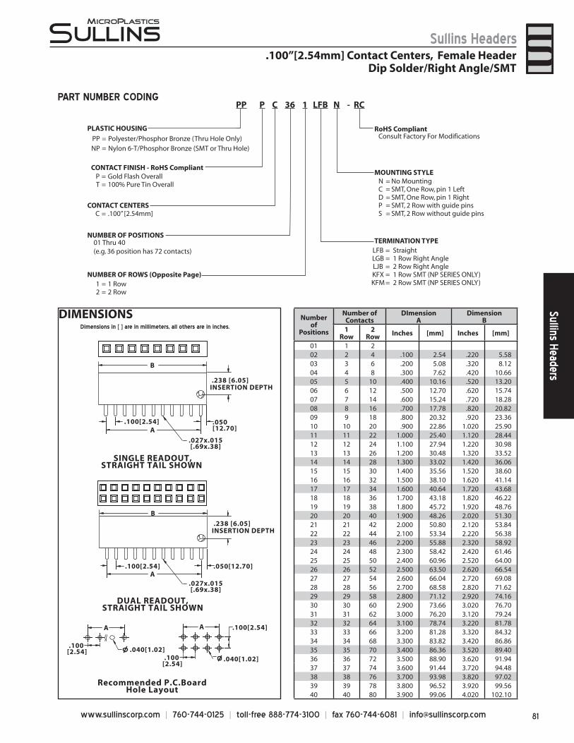
81www.sullinscorp.com | 760-744-0125 | toll-free 888-774-3100 | fax 760-744-6081 | [email protected]
Sullins HeadersSullins Headers
DIMENSIONSDimensions in [ ] are in millimeters, all others are in inches.
SINGLE READOUT,STRAIGHT TAIL SHOWN
.027x.015[.69x.38]
Recommended P.C.BoardHole Layout
DUAL READOUT,STRAIGHT TAIL SHOWN
.238 [6.05]INSERTION DEPTH
.100[2.54]
.040[1.02]
.050[12.70]
.100[2.54]
.238 [6.05]INSERTION DEPTH
B
A
B
.027x.015[.69x.38]
.050[12.70] .100[2.54]A
A
.100[2.54]
.040[1.02]
A
.100[2.54]
Number of
Positions
Number of Contacts
DImensionA
DimensionB
1 Row
2 Row Inches [mm] Inches [mm]
01 1 202 2 4 .100 2.54 .220 5.5803 3 6 .200 5.08 .320 8.1204 4 8 .300 7.62 .420 10.6605 5 10 .400 10.16 .520 13.2006 6 12 .500 12.70 .620 15.7407 7 14 .600 15.24 .720 18.2808 8 16 .700 17.78 .820 20.8209 9 18 .800 20.32 .920 23.3610 10 20 .900 22.86 1.020 25.9011 11 22 1.000 25.40 1.120 28.4412 12 24 1.100 27.94 1.220 30.9813 13 26 1.200 30.48 1.320 33.5214 14 28 1.300 33.02 1.420 36.0615 15 30 1.400 35.56 1.520 38.6016 16 32 1.500 38.10 1.620 41.1417 17 34 1.600 40.64 1.720 43.6818 18 36 1.700 43.18 1.820 46.2219 19 38 1.800 45.72 1.920 48.7620 20 40 1.900 48.26 2.020 51.3021 21 42 2.000 50.80 2.120 53.8422 22 44 2.100 53.34 2.220 56.3823 23 46 2.200 55.88 2.320 58.9224 24 48 2.300 58.42 2.420 61.4625 25 50 2.400 60.96 2.520 64.0026 26 52 2.500 63.50 2.620 66.5427 27 54 2.600 66.04 2.720 69.0828 28 56 2.700 68.58 2.820 71.6229 29 58 2.800 71.12 2.920 74.1630 30 60 2.900 73.66 3.020 76.7031 31 62 3.000 76.20 3.120 79.2432 32 64 3.100 78.74 3.220 81.7833 33 66 3.200 81.28 3.320 84.3234 34 68 3.300 83.82 3.420 86.8635 35 70 3.400 86.36 3.520 89.4036 36 72 3.500 88.90 3.620 91.9437 37 74 3.600 91.44 3.720 94.4838 38 76 3.700 93.98 3.820 97.0239 39 78 3.800 96.52 3.920 99.5640 40 80 3.900 99.06 4.020 102.10
PART NUMBER CODING
.100”[2.54mm] Contact Centers, Female HeaderDip Solder/Right Angle/SMT
PLASTIC HOUSING
PP = Polyester/Phosphor Bronze (Thru Hole Only)NP = Nylon 6-T/Phosphor Bronze (SMT or Thru Hole)
P = Gold Flash OverallT = 100% Pure Tin Overall
CONTACT FINISH - RoHS Compliant
CONTACT CENTERS
NUMBER OF POSITIONS
1 = 1 Row2 = 2 Row
RoHS Compliant
MOUNTING STYLE
Consult Factory For Modifications
N = No MountingC = SMT, One Row, pin 1 LeftD = SMT, One Row, pin 1 RightP = SMT, 2 Row with guide pinsS = SMT, 2 Row without guide pins
TERMINATION TYPE01 Thru 40(e.g. 36 position has 72 contacts)
NUMBER OF ROWS (Opposite Page)
LFB = StraightLGB = 1 Row Right AngleLJB = 2 Row Right AngleKFX = 1 Row SMT (NP SERIES ONLY)KFM = 2 Row SMT (NP SERIES ONLY)
PP P C 36 1 LFB N - RC
C = .100” [2.54mm]
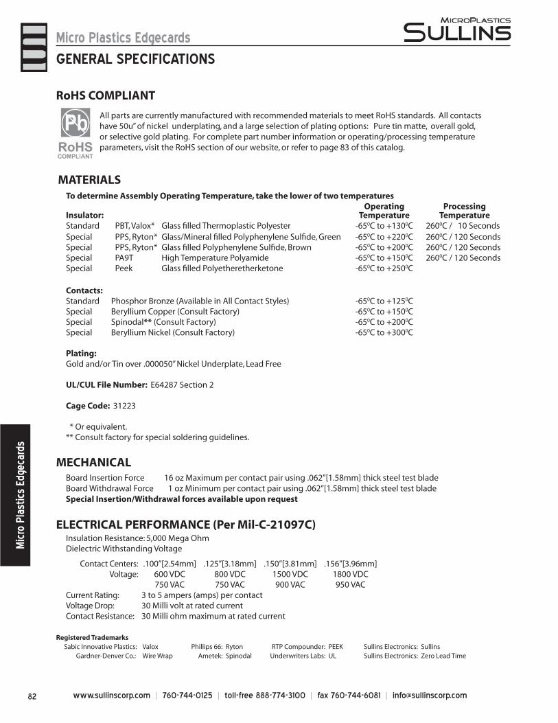
www.sullinscorp.com | 760-744-0125 | toll-free 888-774-3100 | fax 760-744-6081 | [email protected]
Micro Plastics EdgecardsM
icro
Pla
stic
s Ed
geca
rds
MATERIALSTo determine Assembly Operating Temperature, take the lower of two temperatures
Insulator:Operating
TemperatureProcessing
TemperatureStandard PBT, Valox* Glass fi lled Thermoplastic Polyester -650C to +1300C 2600C / 10 SecondsSpecial PPS, Ryton* Glass/Mineral fi lled Polyphenylene Sulfi de, Green -650C to +2200C 2600C / 120 SecondsSpecial PPS, Ryton* Glass fi lled Polyphenylene Sulfi de, Brown -650C to +2000C 2600C / 120 SecondsSpecial PA9T High Temperature Polyamide -650C to +1500C 2600C / 120 SecondsSpecial Peek Glass fi lled Polyetheretherketone -650C to +2500C
Contacts:Standard Phosphor Bronze (Available in All Contact Styles) -650C to +1250CSpecial Beryllium Copper (Consult Factory) -650C to +1500CSpecial Spinodal** (Consult Factory) -650C to +2000CSpecial Beryllium Nickel (Consult Factory) -650C to +3000C
Plating:Gold and/or Tin over .000050” Nickel Underplate, Lead Free
UL/CUL File Number: E64287 Section 2
Cage Code: 31223
* Or equivalent.** Consult factory for special soldering guidelines.
GENERAL SPECIFICATIONS
ELECTRICAL PERFORMANCE (Per Mil-C-21097C)Insulation Resistance: 5,000 Mega OhmDielectric Withstanding Voltage
Contact Centers: .100”[2.54mm] .125”[3.18mm] .150”[3.81mm] .156”[3.96mm]Voltage: 600 VDC 800 VDC 1500 VDC 1800 VDC
750 VAC 750 VAC 900 VAC 950 VACCurrent Rating: 3 to 5 ampers (amps) per contactVoltage Drop: 30 Milli volt at rated currentContact Resistance: 30 Milli ohm maximum at rated current
MECHANICAL Board Insertion Force 16 oz Maximum per contact pair using .062”[1.58mm] thick steel test blade Board Withdrawal Force 1 oz Minimum per contact pair using .062”[1.58mm] thick steel test blade Special Insertion/Withdrawal forces available upon request
All parts are currently manufactured with recommended materials to meet RoHS standards. All contacts have 50u” of nickel underplating, and a large selection of plating options: Pure tin matte, overall gold, or selective gold plating. For complete part number information or operating/processing temperature parameters, visit the RoHS section of our website, or refer to page 83 of this catalog.
RoHS COMPLIANT
Registered TrademarksSabic Innovative Plastics: Valox Phillips 66: Ryton RTP Compounder: PEEK Sullins Electronics: Sullins Gardner-Denver Co.: Wire Wrap Ametek: Spinodal Underwriters Labs: UL Sullins Electronics: Zero Lead Time
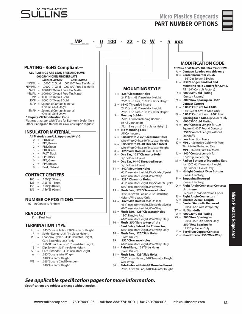
83www.sullinscorp.com | 760-744-0125 | toll-free 888-774-3100 | fax 760-744-6081 | [email protected]
Micro Plastics EdgecardsM
icro Plastics Edgecards
PART NUMBER OPTIONS
INSULATOR MATERIALAll Materials are U.L. Approved 94V-0
0 = PBT, Blue1 = PPS, Brown2 = PBT, Green3 = PBT, Black4 = PA9T, Black5 = PPS, Black6 = PPS, Green7 = PPS, Brown8 = Peek, Natural
CONTACT CENTERS100 = .100” [2.54mm] 125 = .125” [3.18mm] 150 = .150” [3.84mm] 156 = .156” [3.96mm]
NUMBER OF POSITIONS 02 - 70 Contacts Per Row
READOUT
TERMINATION TYPEFS = .045” Square Tails - .720” Insulator Height
P = Solder Eyelet - .431” Insulator HeightPE = Economy Eyelet - .431” Insulator Height,
Card Extender, .156” only R = .026” Round Tails - .610” Insulator Height, S = Dip Solder - .431” Insulator Height
SE = Card Extender - .431” Insulator Height W = .025” Square Wire Wrap -
.610” Insulator Height WE = .025” Square Card Extender -
.610” Insulator Height
MOUNTING STYLE
MODIFICATION CODE
1 = .125” Clearance Holes.245” Ears, .431” Insulator Height.250” Flush Ears, .610” Insulator Height
2 = #4-40 Threaded Insert .245” Ears, .431” Insulator Height .250” Flush Ears, .610” Insulator Height
3 = Floating Bobbin.220” Ears not Including Bobbin on All Connectors (Flush Ears on .610 Insulator Height )
4 = No Mounting Ears All Connectors
5 = Raised with .125” Clearance HolesWire Wrap Only, .610” Insulator Height
6 = Raised with #4-40 Threaded InsertWire Wrap Only, .610” Insulator Height
8 = .125” Side Holes (Cross Drilled) 9 = One Ear, .125” Clearance Hole
Dip Solder & Eyelet 10 = One Ear, #4-40 Threaded Insert
Dip Solder & Eyelet 11 = .142” Mounting Holes
.431” Insulator Height, Dip Solder, Eyelet
.610” Insulator Height, Wire Wrap12 = .128” Clearance Holes
.431” Insulator Height, Dip Solder & Eyelet
.610” Insulator Height, Wire Wrap13 = Flush Ears, .128” Clearance Holes
.430” Ears with Pad on .610” Insulator Height, Wire Wrap Only
14 = .142” Side Holes (Cross Drilled).431” Insulator Height, Dip Solder, Eyelet.610” Insulator Height, Wire Wrap
15 = Flush Ears, .125” Clearance Holes.190” Ears, No Pad .610” Insulator Height, Wire Wrap Only
16 = Flush .250” Ears to top of the Card Entry Side of the Connector, .610” Insulator Height, Wire Wrap Only
18 = Flush Ears, .125” Side Holes (Cross Drilled)
19 = .152” Clearance Holes.610” Insulator Height, Wire Wrap Only
58 = Raised Ears, .125” Side Holes(Cross Drilled)
81 = Flush Ears, .125” Side Holes.250” Ears with Pad, .610” Insulator Height, Wire Wrap
86 = Side Holes with #4-40 Threaded Insert .250” Ears with Pad, .610” Insulator Height
CONSULT FACTORY FOR OTHER OPTIONS A = Contacts Loaded one side onlyB = Center Barrier for 28/56 -
.156” Dip Solder & Eyelet C = .030” Longer Cardslot and
Mounting Hole Centers for 22/44, All .156” (Consult Factory)
D = .000050” Gold Plating - (Consult Factory)
E9 = .200” Row Spacing on .156” Contact Centers
F = 6.802” Cardslot for 43/86.156” Eyelet & Wire Wrap Only
F9 = 6.802” Cardslot and .200” Row Spacing for 43/86 Dip Solder Only
G = .000030” Gold PlatingH = .190” Contact Length for .025”
Square & .026” Round Contacts.250” Contact Length without Standoffs
J = Low Insertion ForceK = MPSL - Selective Gold with Pure
Tin, Matte Plating on TailsMPL - Overall Pure Tin, Matte
L = .140” Contact Length for .156” Dip Solder Only
M = Pad on Bottom of Mounting Ears for .156”, .431” Insulator Height, Dip Solder & Eyelet Only
N = Hi-light Contact ID on Bottom (Consult Factory)
P = Engraving Reversed (Consult Factory)
Q = Right Angle Connector Contacts Untrimmed (Requires ‘R’ Modifi cation Code)
R = Right Angle ConnectorsS = Shorter Overall LengthT = Center Standoffs Removed
.100” & .125” Wire Wrap OnlyTT = No StandoffsU = .000020” Gold Plating
X9 = .200” Row Spacing for .100” & .156” Dip Solder Only.250” Row Spacing for.125” Dip Solder Only
Y = Beryllium Copper ContactsZ = Standoffs on .156” Wire Wrap
_ MP_ _ - 0 100 - 22 - D W - 5 xxx
See applicable specifi cation pages for more information.Specifications are subject to change without notice.
ALL PLATINGS ARE LEAD FREE AND HAVE .000050” NICKEL UNDERPLATE
Contact Surface Termination*MPSL = .000010” Gold .000100” Pure Tin Matte
*EMPSL = .000010” Gold .000100” Pure Tin Matte*MPL = .000100” Overall Pure Tin, Matte
*EMPL = .000100” Overall Pure Tin, MatteMP = .000010” Overall Gold
EMP = .000010” Overall GoldMPP = Spinodal Contact Material
(Overall Gold Only)EMPP = Spinodal Contact Material
(Overall Gold Only)* Requires ‘K’ Modifi cation CodePlatings that start with ‘E’ are for Economy Eyelet OnlyOther Plating and thicknesses available upon request.
D = Dual Row
PLATING - RoHS Compliant
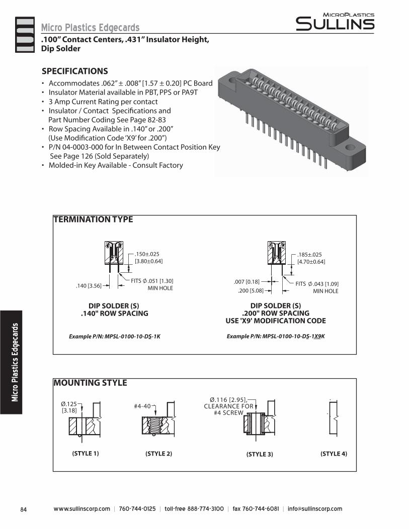
www.sullinscorp.com | 760-744-0125 | toll-free 888-774-3100 | fax 760-744-6081 | [email protected]
Micro Plastics EdgecardsM
icro
Pla
stic
s Ed
geca
rds
SPECIFICATIONS
Acc• ommodates .062” ± .008” [1.57 ± 0.20] PC BoardInsulator Material available in PBT, PPS or PA9T• 3 Amp Current Rating• per contactInsulator / Contact Specifi cations and •
Part Number Coding See Page 82-83Row Spacing Available in .140” or .200” •
(Use Modifi cation Code ‘X9’ for .200”)P/N 04-0003-000 for In Between Contact Position Key•
See Page 126 (Sold Separately) Molded-in Key Available - Consult Factory•
MOUNTING STYLE
TERMINATION TYPE
.185±.025 [4.70±0.64]
.200 [5.08]
.150±.025 [3.80±0.64]
.140 [3.56]
DIP SOLDER (S) .140" ROW SPACING
Example P/N: MPSL-0100-10-DS-1K
DIP SOLDER (S).200" ROW SPACING
USE 'X9' MODIFICATION CODE
Example P/N: MPSL-0100-10-DS-1X9K
FITS .051 [1.30] MIN HOLE
FITS .043 [1.09] MIN HOLE
.007 [0.18]
Ø.125[3.18]
#4-40
(STYLE 1) (STYLE 2) (STYLE 3) (STYLE 4)
Ø.116 [2.95],CLEARANCE FOR
#4 SCREW
.100” Contact Centers, .431” Insulator Height,Dip Solder
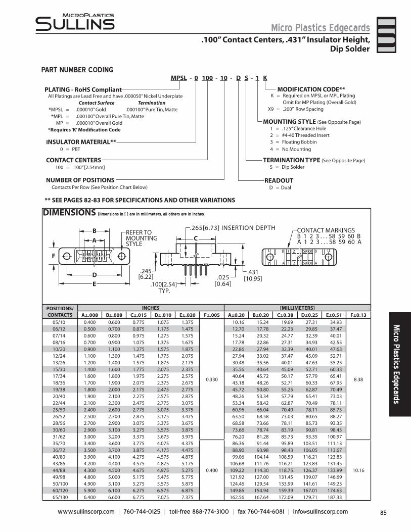
85www.sullinscorp.com | 760-744-0125 | toll-free 888-774-3100 | fax 760-744-6081 | [email protected]
Micro Plastics EdgecardsM
icro Plastics Edgecards
DIMENSIONS Dimensions in [ ] are in millimeters, all others are in inches.
A
D
B
E
FB 1 2 59 60 B
A 1 2 59 60 A
CONTACT MARKINGSB 1 2 3 . . . 58 59 60 BA 1 2 3 . . . 58 59 60 AC
REFER TOMOUNTINGSTYLE
.100[2.54] TYP.
.265[6.73] INSERTION DEPTH
.431[10.95]
.245[6.22] .025
[0.64]
S = Dip Solder
All Platings are Lead Free and have .000050” Nickel UnderplateContact Surface Termination
*MPSL = .000010” Gold .000100” Pure Tin, Matte*MPL = .000100” Overall Pure Tin, Matte
MP = .000010” Overall Gold *Requires ‘K’ Modifi cation Code
PLATING - RoHS CompliantK = Required on MPSL or MPL Plating
Omit for MP Plating (Overall Gold)X9 = .200” Row Spacing
MODIFICATION CODE**
TERMINATION TYPE (See Opposite Page)CONTACT CENTERS100 = .100” [2.54mm]
NUMBER OF POSITIONSContacts Per Row (See Position Chart Below)
INSULATOR MATERIAL**0 = PBT
READOUT
** SEE PAGES 82-83 FOR SPECIFICATIONS AND OTHER VARIATIONS
1 = .125” Clearance Hole2 = #4-40 Threaded Insert3 = Floating Bobbin
4 = No Mounting
MOUNTING STYLE (See Opposite Page)
MPSL - 0 100 - 10 - D S - 1 KPART NUMBER CODING
POSITIONS/CONTACTS
INCHES [MILLIMETERS]A±.008 B±.008 C±.015 D±.010 E±.020 F±.005 A±0.20 B±0.20 C±0.38 D±0.25 E±0.51 F±0.13
05/10 0.400 0.600 0.775 1.075 1.375
0.330
10.16 15.24 19.69 27.31 34.93
8.38
06/12 0.500 0.700 0.875 1.175 1.475 12.70 17.78 22.23 29.85 37.4707/14 0.600 0.800 0.975 1.275 1.575 15.24 20.32 24.77 32.39 40.0108/16 0.700 0.900 1.075 1.375 1.675 17.78 22.86 27.31 34.93 42.5510/20 0.900 1.100 1.275 1.575 1.875 22.86 27.94 32.39 40.01 47.6312/24 1.100 1.300 1.475 1.775 2.075 27.94 33.02 37.47 45.09 52.7113/26 1.200 1.400 1.575 1.875 2.175 30.48 35.56 40.01 47.63 55.2515/30 1.400 1.600 1.775 2.075 2.375 35.56 40.64 45.09 52.71 60.3317/34 1.600 1.800 1.975 2.275 2.575 40.64 45.72 50.17 57.79 65.4118/36 1.700 1.900 2.075 2.375 2.675 43.18 48.26 52.71 60.33 67.9519/38 1.800 2.000 2.175 2.475 2.775 45.72 50.80 55.25 62.87 70.4920/40 1.900 2.100 2.275 2.575 2.875 48.26 53.34 57.79 65.41 73.0322/44 2.100 2.300 2.475 2.775 3.075 53.34 58.42 62.87 70.49 78.1125/50 2.400 2.600 2.775 3.075 3.375 60.96 66.04 70.49 78.11 85.7326/52 2.500 2.700 2.875 3.175 3.475 63.50 68.58 73.03 80.65 88.2728/56 2.700 2.900 3.075 3.375 3.675 68.58 73.66 78.11 85.73 93.3530/60 2.900 3.100 3.275 3.575 3.875 73.66 78.74 83.19 90.81 98.4331/62 3.000 3.200 3.375 3.675 3.975 76.20 81.28 85.73 93.35 100.9735/70 3.400 3.600 3.775 4.075 4.375
0.400
86.36 91.44 95.89 103.51 111.13
10.16
36/72 3.500 3.700 3.875 4.175 4.475 88.90 93.98 98.43 106.05 113.6740/80 3.900 4.100 4.275 4.575 4.875 99.06 104.14 108.59 116.21 123.8343/86 4.200 4.400 4.575 4.875 5.175 106.68 111.76 116.21 123.83 131.4544/88 4.300 4.500 4.675 4.975 5.275 109.22 114.30 118.75 126.37 133.9949/98 4.800 5.000 5.175 5.475 5.775 121.92 127.00 131.45 139.07 146.6950/100 4.900 5.100 5.275 5.575 5.875 124.46 129.54 133.99 141.61 149.2360/120 5.900 6.100 6.275 6.575 6.875 149.86 154.94 159.39 167.01 174.6365/130 6.400 6.600 6.775 7.075 7.375 162.56 167.64 172.09 179.71 187.33
.100” Contact Centers, .431” Insulator Height,Dip Solder
D = Dual
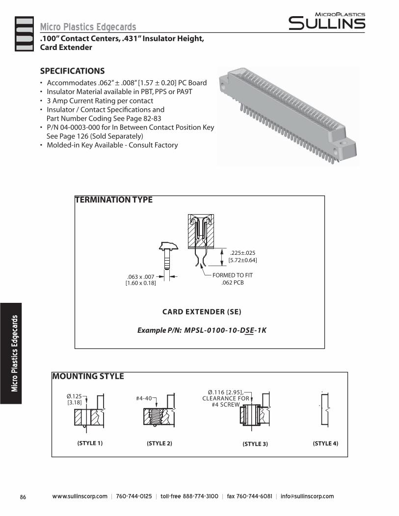
www.sullinscorp.com | 760-744-0125 | toll-free 888-774-3100 | fax 760-744-6081 | [email protected]
Micro Plastics EdgecardsM
icro
Pla
stic
s Ed
geca
rds
SPECIFICATIONSAccommo• dates .062” ± .008” [1.57 ± 0.20] PC BoardInsulator Material available in PBT, PPS or PA9T• 3 Amp Current Rating • per contactInsulator / Contact Specifi cations and •
Part Number Coding See Page 82-83P/N 04-0003-000 for In Between Contact Position Key •
See Page 126 (Sold Separately)Molded-in Key Available - Consult Factory•
MOUNTING STYLE
TERMINATION TYPE
.225±.025[5.72±0.64]
FORMED TO FIT.062 PCB
CARD EXTENDER (SE)
Example P/N: MPSL-0100-10-DSE-1K
.063 x .007[1.60 x 0.18]
Ø.125[3.18]
#4-40
(STYLE 1) (STYLE 2) (STYLE 3) (STYLE 4)
Ø.116 [2.95],CLEARANCE FOR
#4 SCREW
.100” Contact Centers, .431” Insulator Height,Card Extender
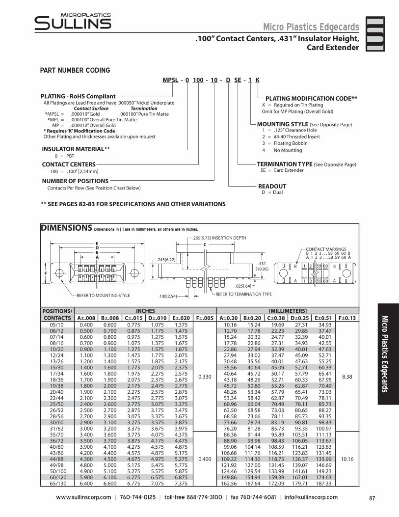
87www.sullinscorp.com | 760-744-0125 | toll-free 888-774-3100 | fax 760-744-6081 | [email protected]
Micro Plastics EdgecardsM
icro Plastics Edgecards
DIMENSIONS Dimensions in [ ] are in millimeters, all others are in inches.
CONTACT CENTERS100 = .100” [2.54mm]
NUMBER OF POSITIONSContacts Per Row (See Position Chart Below)
1 = .125” Clearance Hole2 = #4-40 Threaded Insert3 = Floating Bobbin
4 = No Mounting
SE = Card Extender
INSULATOR MATERIAL**0 = PBT
K = Required on Tin PlatingOmit for MP Plating (Overall Gold)
PLATING MODIFICATION CODE**
MOUNTING STYLE (See Opposite Page)
TERMINATION TYPE (See Opposite Page)
READOUT
** SEE PAGES 82-83 FOR SPECIFICATIONS AND OTHER VARIATIONS
All Platings are Lead Free and have .000050” Nickel UnderplateContact Surface Termination
*MPSL = .000010” Gold .000100” Pure Tin Matte*MPL = .000100” Overall Pure Tin, Matte
MP = .000010” Overall Gold* Requires ‘K’ Modifi cation CodeOther Plating and thicknesses available upon request
MPSL - 0 100 - 10 - D SE - 1 K
C
.025[.64]
.245[6.22].431
[10.95]
.100[2.54]
BA
DE
.265[6.73] INSERTION DEPTH
REFER TO TERMINATION TYPE
F
B
A
B
A
1 2 59 60
1 2 59 60
CONTACT MARKINGSB 1 2 3 . . . 58 59 60 BA 1 2 3 . . . 58 59 60 A
REFER TO MOUNTING STYLE
PART NUMBER CODING
.100” Contact Centers, .431” Insulator Height,Card Extender
POSITIONS/CONTACTS
INCHES [MILLIMETERS]A±.008 B±.008 C±.015 D±.010 E±.020 F±.005 A±0.20 B±0.20 C±0.38 D±0.25 E±0.51 F±0.13
05/10 0.400 0.600 0.775 1.075 1.375
0.330
10.16 15.24 19.69 27.31 34.93
8.38
06/12 0.500 0.700 0.875 1.175 1.475 12.70 17.78 22.23 29.85 37.4707/14 0.600 0.800 0.975 1.275 1.575 15.24 20.32 24.77 32.39 40.0108/16 0.700 0.900 1.075 1.375 1.675 17.78 22.86 27.31 34.93 42.5510/20 0.900 1.100 1.275 1.575 1.875 22.86 27.94 32.39 40.01 47.6312/24 1.100 1.300 1.475 1.775 2.075 27.94 33.02 37.47 45.09 52.7113/26 1.200 1.400 1.575 1.875 2.175 30.48 35.56 40.01 47.63 55.2515/30 1.400 1.600 1.775 2.075 2.375 35.56 40.64 45.09 52.71 60.3317/34 1.600 1.800 1.975 2.275 2.575 40.64 45.72 50.17 57.79 65.4118/36 1.700 1.900 2.075 2.375 2.675 43.18 48.26 52.71 60.33 67.9519/38 1.800 2.000 2.175 2.475 2.775 45.72 50.80 55.25 62.87 70.4920/40 1.900 2.100 2.275 2.575 2.875 48.26 53.34 57.79 65.41 73.0322/44 2.100 2.300 2.475 2.775 3.075 53.34 58.42 62.87 70.49 78.1125/50 2.400 2.600 2.775 3.075 3.375 60.96 66.04 70.49 78.11 85.7326/52 2.500 2.700 2.875 3.175 3.475 63.50 68.58 73.03 80.65 88.2728/56 2.700 2.900 3.075 3.375 3.675 68.58 73.66 78.11 85.73 93.3530/60 2.900 3.100 3.275 3.575 3.875 73.66 78.74 83.19 90.81 98.4331/62 3.000 3.200 3.375 3.675 3.975 76.20 81.28 85.73 93.35 100.9735/70 3.400 3.600 3.775 4.075 4.375
0.400
86.36 91.44 95.89 103.51 111.13
10.16
36/72 3.500 3.700 3.875 4.175 4.475 88.90 93.98 98.43 106.05 113.6740/80 3.900 4.100 4.275 4.575 4.875 99.06 104.14 108.59 116.21 123.8343/86 4.200 4.400 4.575 4.875 5.175 106.68 111.76 116.21 123.83 131.4544/88 4.300 4.500 4.675 4.975 5.275 109.22 114.30 118.75 126.37 133.9949/98 4.800 5.000 5.175 5.475 5.775 121.92 127.00 131.45 139.07 146.6950/100 4.900 5.100 5.275 5.575 5.875 124.46 129.54 133.99 141.61 149.2360/120 5.900 6.100 6.275 6.575 6.875 149.86 154.94 159.39 167.01 174.6365/130 6.400 6.600 6.775 7.075 7.375 162.56 167.64 172.09 179.71 187.33
D = Dual
PLATING - RoHS Compliant
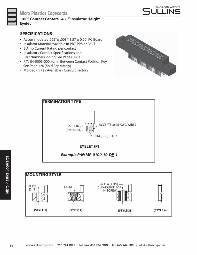
www.sullinscorp.com | 760-744-0125 | toll-free 888-774-3100 | fax 760-744-6081 | [email protected]
Micro Plastics EdgecardsM
icro
Pla
stic
s Ed
geca
rds
MOUNTING STYLE
Ø.125[3.18]
#4-40
(STYLE 1) (STYLE 2) (STYLE 3) (STYLE 4)
Ø.116 [2.95],CLEARANCE FOR
#4 SCREW
TERMINATION TYPE
EYELET (P)
Example P/N: MP-0100-10-DP-1
.275±.025[6.99±0.64]
ACCEPTS 3#26 AWG WIRES
.014 [0.36] THICK
SPECIFICATIONSAccommo• dates .062” ± .008” [1.57 ± 0.20] PC BoardInsulator Material available in PBT, PPS or PA9T• 3 Amp Current Rating • per contactInsulator / Contact Specifi cations and • Part Number Coding See Page 82-83• P/N 04-0003-000 for In Between Contact Position Key •
See Page 126 (Sold Separately)Molded-in Key Available - Consult Factory•
.100” Contact Centers, .431” Insulator Height,Eyelet
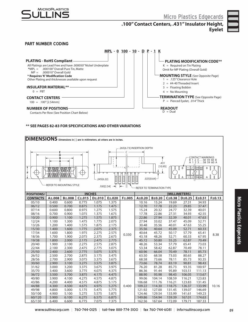
89www.sullinscorp.com | 760-744-0125 | toll-free 888-774-3100 | fax 760-744-6081 | [email protected]
Micro Plastics EdgecardsM
icro Plastics Edgecards
DIMENSIONS Dimensions in [ ] are in millimeters, all others are in inches.
POSITIONS/CONTACTS
INCHES [MILLIMETERS]A±.008 B±.008 C±.015 D±.010 E±.020 F±.005 A±0.20 B±0.20 C±0.38 D±0.25 E±0.51 F±0.13
05/10 0.400 0.600 0.775 1.075 1.375
0.330
10.16 15.24 19.69 27.31 34.93
8.38
06/12 0.500 0.700 0.875 1.175 1.475 12.70 17.78 22.23 29.85 37.4707/14 0.600 0.800 0.975 1.275 1.575 15.24 20.32 24.77 32.39 40.0108/16 0.700 0.900 1.075 1.375 1.675 17.78 22.86 27.31 34.93 42.5510/20 0.900 1.100 1.275 1.575 1.875 22.86 27.94 32.39 40.01 47.6312/24 1.100 1.300 1.475 1.775 2.075 27.94 33.02 37.47 45.09 52.7113/26 1.200 1.400 1.575 1.875 2.175 30.48 35.56 40.01 47.63 55.2515/30 1.400 1.600 1.775 2.075 2.375 35.56 40.64 45.09 52.71 60.3317/34 1.600 1.800 1.975 2.275 2.575 40.64 45.72 50.17 57.79 65.4118/36 1.700 1.900 2.075 2.375 2.675 43.18 48.26 52.71 60.33 67.9519/38 1.800 2.000 2.175 2.475 2.775 45.72 50.80 55.25 62.87 70.4920/40 1.900 2.100 2.275 2.575 2.875 48.26 53.34 57.79 65.41 73.0322/44 2.100 2.300 2.475 2.775 3.075 53.34 58.42 62.87 70.49 78.1125/50 2.400 2.600 2.775 3.075 3.375 60.96 66.04 70.49 78.11 85.7326/52 2.500 2.700 2.875 3.175 3.475 63.50 68.58 73.03 80.65 88.2728/56 2.700 2.900 3.075 3.375 3.675 68.58 73.66 78.11 85.73 93.3530/60 2.900 3.100 3.275 3.575 3.875 73.66 78.74 83.19 90.81 98.4331/62 3.000 3.200 3.375 3.675 3.975 76.20 81.28 85.73 93.35 100.9735/70 3.400 3.600 3.775 4.075 4.375
0.400
86.36 91.44 95.89 103.51 111.13
10.16
36/72 3.500 3.700 3.875 4.175 4.475 88.90 93.98 98.43 106.05 113.6740/80 3.900 4.100 4.275 4.575 4.875 99.06 104.14 108.59 116.21 123.8343/86 4.200 4.400 4.575 4.875 5.175 106.68 111.76 116.21 123.83 131.4544/88 4.300 4.500 4.675 4.975 5.275 109.22 114.30 118.75 126.37 133.9949/98 4.800 5.000 5.175 5.475 5.775 121.92 127.00 131.45 139.07 146.6950/100 4.900 5.100 5.275 5.575 5.875 124.46 129.54 133.99 141.61 149.2360/120 5.900 6.100 6.275 6.575 6.875 149.86 154.94 159.39 167.01 174.6365/130 6.400 6.600 6.775 7.075 7.375 162.56 167.64 172.09 179.71 187.33
C
.245[6.22]
.431[10.95]
.025[0.64]
EDB
.100[2.54]
A
REFER TO MOUNTING STYLE
F
.265[6.73] INSERTION DEPTH
REFER TO TERMINATION TYPE
B
A
B
A
1 2 59 60
1 2 59 60
CONTACT MARKINGSB 1 2 3 . . . 58 59 60 BA 1 2 3 . . . 58 59 60 A
PART NUMBER CODING
.100” Contact Centers, .431” Insulator Height,Eyelet
CONTACT CENTERS100 = .100” [2.54mm]
NUMBER OF POSITIONSContacts Per Row (See Position Chart Below)
1 = .125” Clearance Hole2 = #4-40 Threaded Insert3 = Floating Bobbin
4 = No Mounting
P = Pierced Eyelet, .014” Thick
INSULATOR MATERIAL**0 = PBT
PLATING MODIFICATION CODE**
MOUNTING STYLE (See Opposite Page)
TERMINATION TYPE (See Opposite Page)
READOUT
** SEE PAGES 82-83 FOR SPECIFICATIONS AND OTHER VARIATIONS
K = Required on Tin PlatingOmit for MP Plating (Overall Gold)
All Platings are Lead Free and have .000050” Nickel Underplate*MPL = .000100” Overall Pure Tin, Matte
MP = .000010” Overall Gold* Requires ‘K’ Modifi cation CodeOther Plating and thicknesses available upon request
MPL - 0 100 - 10 - D P - 1 K
D = Dual
PLATING - RoHS Compliant
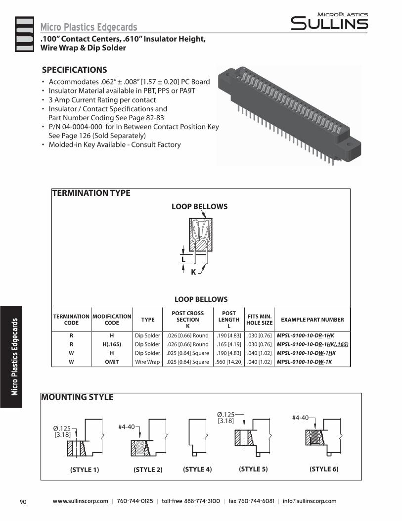
www.sullinscorp.com | 760-744-0125 | toll-free 888-774-3100 | fax 760-744-6081 | [email protected]
Micro Plastics EdgecardsM
icro
Pla
stic
s Ed
geca
rds
MOUNTING STYLE
Ø.125 [3.18]
(STYLE 1) (STYLE 2)
#4-40
(STYLE 6)
#4-40
(STYLE 4) (STYLE 5)
Ø.125[3.18]
SPECIFICATIONSAccommo• dates .062” ± .008” [1.57 ± 0.20] PC BoardInsulator Material available in PBT, PPS or PA9T• 3 Amp Current Rating • per contactInsulator / Contact Specifi cations and •
Part Number Coding See Page 82-83P/N 04-0004-000 for In Between Contact Position Key •
See Page 126 (Sold Separately)Molded-in Key Available - Consult Factory•
.100” Contact Centers, .610” Insulator Height,Wire Wrap & Dip Solder
LOOP BELLOWS
K
L
LOOP BELLOWS
TERMINATIONCODE
MODIFICATION CODE
TYPEPOST CROSS
SECTIONK
POST LENGTH
L
FITS MIN.HOLE SIZE
EXAMPLE PART NUMBER
R H Dip Solder .026 [0.66] Round .190 [4.83] .030 [0.76] MPSL-0100-10-DR-1HK
R H(.165) Dip Solder .026 [0.66] Round .165 [4.19] .030 [0.76] MPSL-0100-10-DR-1HK(.165)
W H Dip Solder .025 [0.64] Square .190 [4.83] .040 [1.02] MPSL-0100-10-DW-1HK
W OMIT Wire Wrap .025 [0.64] Square .560 [14.20] .040 [1.02] MPSL-0100-10-DW-1K
TERMINATION TYPE

91www.sullinscorp.com | 760-744-0125 | toll-free 888-774-3100 | fax 760-744-6081 | [email protected]
Micro Plastics EdgecardsM
icro Plastics Edgecards
DIMENSIONS Dimensions in [ ] are in millimeters, all others are in inches.
1 3 5 7 9 131 133 135137 139
2 4 6 8 10 132 134 136 138 140
AB
C
DE F
REFER TO MOUNTING STYLE
REFER TO TERMINATION TYPE
.297 [7.54] INSERTION DEPTH .180 [4.57]
.250[6.35]
.060[1.52] .100 [2.54] .313
[7.95]
.610[15.49]
.370[9.40]
.200 [5.08]
CONTACT MARKINGS1 3 5 . . . 137 1392 4 6 . . . 138 140
1 = .125” Clearance Hole2 = #4-40 Threaded Insert4 = No Mounting5 = Raised, .125” Clearance Hole6 = Raised, #4-40 Threaded Insert
LOOP BELLOWSR = .026[.66mm] Round
W = .025[.64mm] Square
All Platings are Lead Free and have .000050” Nickel UnderplateContact Surface Termination
*MPSL = .000010” Gold .000100” Pure Tin, Matte*MPL = .000100” Overall Pure Tin, Matte
MP = .000010” Overall Gold *Requires ‘K’ Modifi cation Code
MODIFICATION CODE** (See Opposite Page)
MOUNTING STYLE (See Opposite Page)
TERMINATION TYPE (See Opposite Page)
H = Dip Solder .190[4.83] Tail Length(.026 Round or .025 Square)
H(.165) = Dip Solder .165[4.19] Tail Length(.026 Round Only)
CONTACT CENTERS100 = .100” [2.54mm]
NUMBER OF POSITIONSContacts Per Row (See Position Chart Below)
INSULATOR MATERIAL**0 = PBT
READOUT
** SEE PAGES 82-83 FOR SPECIFICATIONS AND OTHER VARIATIONS
K = Required on MPSL or MPL PlatingOmit for MP Plating (Overall Gold)
PLATING MODIFICATION CODE**
MPSL - 0 100 - 10 - D W - 1 H K
PART NUMBER CODING
POSITIONS/CONTACTS
INCHES [MILLIMETERS]A±.008 B±.008 C±.015 D±.010 E±.020 F±.015 A±0.20 B±0.20 C±0.38 D±0.25 E±0.51 F±0.38
06/12 0.500 0.700 0.860 1.175 1.435 0.750 12.70 17.78 21.84 29.85 36.45 19.0508/16 0.700 0.900 1.060 1.375 1.635 0.950 17.78 22.86 26.92 34.93 41.53 24.1310/20 0.900 1.100 1.260 1.575 1.835 1.150 22.86 27.94 32.00 40.01 46.61 29.2112/24 1.100 1.300 1.460 1.775 2.035 1.350 27.94 33.02 37.08 45.09 51.69 34.2913/26 1.200 1.400 1.560 1.875 2.135 1.450 30.48 35.56 39.62 47.63 54.23 36.8315/30 1.400 1.600 1.760 2.075 2.335 1.650 35.56 40.64 44.70 52.71 59.31 41.9117/34 1.600 1.800 1.960 2.275 2.535 1.850 40.64 45.72 49.78 57.79 64.39 46.9918/36 1.700 1.900 2.060 2.375 2.635 1.950 43.18 48.26 52.32 60.33 66.93 49.5320/40 1.900 2.100 2.260 2.575 2.835 2.150 48.26 53.34 57.40 65.41 72.01 54.6122/44 2.100 2.300 2.460 2.775 3.035 2.350 53.34 58.42 62.48 70.49 77.09 59.6924/48 2.300 2.500 2.660 2.975 3.235 2.550 58.42 63.50 67.56 75.57 82.17 64.7725/50 2.400 2.600 2.760 3.075 3.335 2.650 60.96 66.04 70.10 78.11 84.71 67.3128/56 2.700 2.900 3.060 3.375 3.635 2.950 68.58 73.66 77.72 85.73 92.33 74.9330/60 2.900 3.100 3.260 3.575 3.835 3.150 73.66 78.74 82.80 90.81 97.41 80.0131/62 3.000 3.200 3.360 3.675 3.935 3.250 76.20 81.28 85.34 93.35 99.95 82.5535/70 3.400 3.600 3.760 4.075 4.335 3.650 86.36 91.44 95.50 103.51 110.11 92.7136/72 3.500 3.700 3.860 4.175 4.435 3.750 88.90 93.98 98.04 106.05 112.65 95.2540/80 3.900 4.100 4.260 4.575 4.835 4.150 99.06 104.14 108.20 116.21 122.81 105.4143/86 4.200 4.400 4.560 4.875 5.135 4.450 106.68 111.76 115.82 123.83 130.43 113.0344/88 4.300 4.500 4.660 4.975 5.235 4.550 109.22 114.30 118.36 126.37 132.97 115.5750/100 4.900 5.100 5.260 5.575 5.835 5.150 124.46 129.54 133.60 141.61 148.21 130.8155/110 5.400 5.600 5.760 6.075 6.335 5.650 137.16 142.24 146.30 154.31 160.91 143.5160/120 5.900 6.100 6.260 6.575 6.835 6.150 149.86 154.94 159.00 167.01 173.61 156.2161/122 6.000 6.200 6.360 6.675 6.935 6.250 152.40 157.48 161.54 169.55 176.15 158.7565/130 6.400 6.600 6.760 7.075 7.335 6.650 162.56 167.64 171.70 179.71 186.31 168.9170/140 6.900 7.100 7.260 7.575 7.835 7.150 175.26 180.34 184.40 192.41 199.01 181.61
.100” Contact Centers, .610” Insulator Height,Wire Wrap & Dip Solder
D = Dual
PLATING - RoHS Compliant
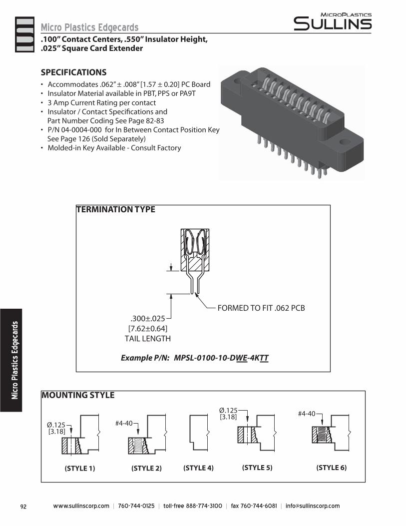
www.sullinscorp.com | 760-744-0125 | toll-free 888-774-3100 | fax 760-744-6081 | [email protected]
Micro Plastics EdgecardsM
icro
Pla
stic
s Ed
geca
rds
MOUNTING STYLE
TERMINATION TYPE
FORMED TO FIT .062 PCB.300±.025
[7.62±0.64]TAIL LENGTH
Example P/N: MPSL-0100-10-DWE-4KTT
Ø.125 [3.18]
(STYLE 1) (STYLE 2)
#4-40
(STYLE 6)
#4-40
(STYLE 4) (STYLE 5)
Ø.125[3.18]
SPECIFICATIONSAccommo• dates .062” ± .008” [1.57 ± 0.20] PC BoardInsulator Material available in PBT, PPS or PA9T• 3 Amp Current Rating • per contactInsulator / Contact Specifi cations and •
Part Number Coding See Page 82-83P/N 04-0004-000 for In Between Contact Position Key •
See Page 126 (Sold Separately)Molded-in Key Available - Consult Factory•
.100” Contact Centers, .550” Insulator Height,
.025” Square Card Extender
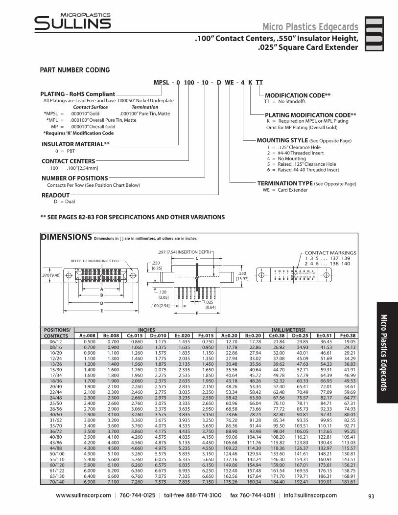
93www.sullinscorp.com | 760-744-0125 | toll-free 888-774-3100 | fax 760-744-6081 | [email protected]
Micro Plastics EdgecardsM
icro Plastics Edgecards
DIMENSIONS Dimensions in [ ] are in millimeters, all others are in inches.
.250[6.35]
.550[13.97]
.025[0.64]
F
C
.120[3.05]
E
D
B
.100 [2.54]
A
.370 [9.40]
REFER TO MOUNTING STYLE
.297 [7.54] INSERTION DEPTH
1 3 5 7 9 131 133 135137 139
2 4 6 8 10 132 134 136 138 140
CONTACT MARKINGS1 3 5 . . . 137 1392 4 6 . . . 138 140
1 = .125” Clearance Hole2 = #4-40 Threaded Insert4 = No Mounting5 = Raised, .125” Clearance Hole6 = Raised, #4-40 Threaded Insert
All Platings are Lead Free and have .000050” Nickel UnderplateContact Surface Termination
*MPSL = .000010” Gold .000100” Pure Tin, Matte*MPL = .000100” Overall Pure Tin, Matte
MP = .000010” Overall Gold *Requires ‘K’ Modifi cation Code
MOUNTING STYLE (See Opposite Page)
TERMINATION TYPE (See Opposite Page)
TT = No Standoffs
WE = Card Extender
CONTACT CENTERS100 = .100” [2.54mm]
NUMBER OF POSITIONSContacts Per Row (See Position Chart Below)
INSULATOR MATERIAL**0 = PBT
READOUT
** SEE PAGES 82-83 FOR SPECIFICATIONS AND OTHER VARIATIONS
K = Required on MPSL or MPL PlatingOmit for MP Plating (Overall Gold)
PLATING MODIFICATION CODE**
MODIFICATION CODE**
MPSL - 0 100 - 10 - D WE - 4 K TT
PART NUMBER CODING
.100” Contact Centers, .550” Insulator Height,.025” Square Card Extender
D = Dual
POSITIONS/CONTACTS
INCHES [MILLIMETERS]A±.008 B±.008 C±.015 D±.010 E±.020 F±.015 A±0.20 B±0.20 C±0.38 D±0.25 E±0.51 F±0.38
06/12 0.500 0.700 0.860 1.175 1.435 0.750 12.70 17.78 21.84 29.85 36.45 19.0508/16 0.700 0.900 1.060 1.375 1.635 0.950 17.78 22.86 26.92 34.93 41.53 24.1310/20 0.900 1.100 1.260 1.575 1.835 1.150 22.86 27.94 32.00 40.01 46.61 29.2112/24 1.100 1.300 1.460 1.775 2.035 1.350 27.94 33.02 37.08 45.09 51.69 34.2913/26 1.200 1.400 1.560 1.875 2.135 1.450 30.48 35.56 39.62 47.63 54.23 36.8315/30 1.400 1.600 1.760 2.075 2.335 1.650 35.56 40.64 44.70 52.71 59.31 41.9117/34 1.600 1.800 1.960 2.275 2.535 1.850 40.64 45.72 49.78 57.79 64.39 46.9918/36 1.700 1.900 2.060 2.375 2.635 1.950 43.18 48.26 52.32 60.33 66.93 49.5320/40 1.900 2.100 2.260 2.575 2.835 2.150 48.26 53.34 57.40 65.41 72.01 54.6122/44 2.100 2.300 2.460 2.775 3.035 2.350 53.34 58.42 62.48 70.49 77.09 59.6924/48 2.300 2.500 2.660 2.975 3.235 2.550 58.42 63.50 67.56 75.57 82.17 64.7725/50 2.400 2.600 2.760 3.075 3.335 2.650 60.96 66.04 70.10 78.11 84.71 67.3128/56 2.700 2.900 3.060 3.375 3.635 2.950 68.58 73.66 77.72 85.73 92.33 74.9330/60 2.900 3.100 3.260 3.575 3.835 3.150 73.66 78.74 82.80 90.81 97.41 80.0131/62 3.000 3.200 3.360 3.675 3.935 3.250 76.20 81.28 85.34 93.35 99.95 82.5535/70 3.400 3.600 3.760 4.075 4.335 3.650 86.36 91.44 95.50 103.51 110.11 92.7136/72 3.500 3.700 3.860 4.175 4.435 3.750 88.90 93.98 98.04 106.05 112.65 95.2540/80 3.900 4.100 4.260 4.575 4.835 4.150 99.06 104.14 108.20 116.21 122.81 105.4143/86 4.200 4.400 4.560 4.875 5.135 4.450 106.68 111.76 115.82 123.83 130.43 113.0344/88 4.300 4.500 4.660 4.975 5.235 4.550 109.22 114.30 118.36 126.37 132.97 115.5750/100 4.900 5.100 5.260 5.575 5.835 5.150 124.46 129.54 133.60 141.61 148.21 130.8155/110 5.400 5.600 5.760 6.075 6.335 5.650 137.16 142.24 146.30 154.31 160.91 143.5160/120 5.900 6.100 6.260 6.575 6.835 6.150 149.86 154.94 159.00 167.01 173.61 156.2161/122 6.000 6.200 6.360 6.675 6.935 6.250 152.40 157.48 161.54 169.55 176.15 158.7565/130 6.400 6.600 6.760 7.075 7.335 6.650 162.56 167.64 171.70 179.71 186.31 168.9170/140 6.900 7.100 7.260 7.575 7.835 7.150 175.26 180.34 184.40 192.41 199.01 181.61
PLATING - RoHS Compliant
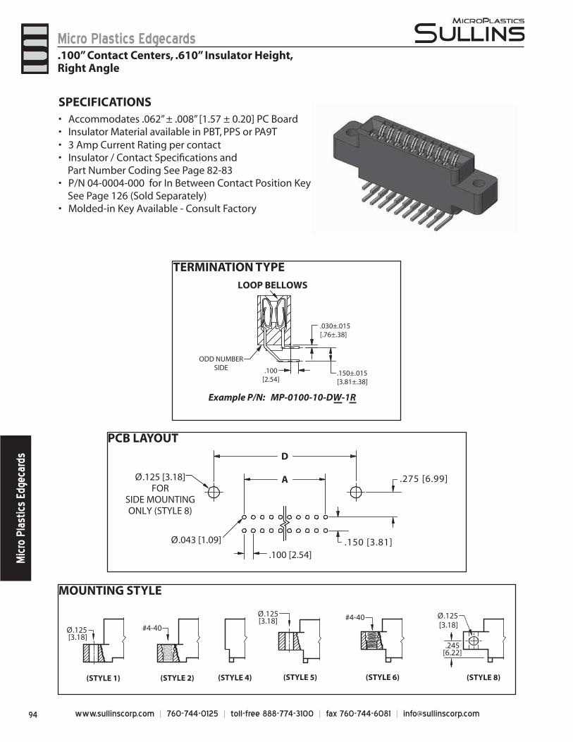
www.sullinscorp.com | 760-744-0125 | toll-free 888-774-3100 | fax 760-744-6081 | [email protected]
Micro Plastics EdgecardsM
icro
Pla
stic
s Ed
geca
rds
MOUNTING STYLE
TERMINATION TYPE
PCB LAYOUT
.030±.015[.76±.38]
.150±.015[3.81±.38]
ODD NUMBERSIDE
LOOP BELLOWS
Example P/N: MP-0100-10-DW-1R
.100[2.54]
.100 [2.54]
A
D
Ø.125 [3.18]FOR
SIDE MOUNTINGONLY (STYLE 8)
Ø.043 [1.09] .150 [3.81]
.275 [6.99]
SPECIFICATIONSAccommo• dates .062” ± .008” [1.57 ± 0.20] PC BoardInsulator Material available in PBT, PPS or PA9T• 3 Amp Current Rating • per contactInsulator / Contact Specifi cations and •
Part Number Coding See Page 82-83P/N 04-0004-000 for In Between Contact Position Key •
See Page 126 (Sold Separately)Molded-in Key Available - Consult Factory•
.100” Contact Centers, .610” Insulator Height,Right Angle
(STYLE 8)
.245[6.22]
Ø.125[3.18]
Ø.125 [3.18]
(STYLE 1) (STYLE 2)
#4-40
(STYLE 6)
#4-40
(STYLE 4) (STYLE 5)
Ø.125[3.18]
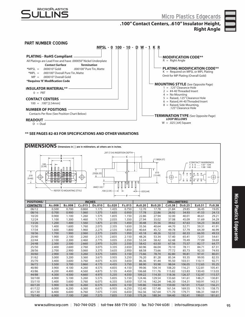
95www.sullinscorp.com | 760-744-0125 | toll-free 888-774-3100 | fax 760-744-6081 | [email protected]
Micro Plastics EdgecardsM
icro Plastics Edgecards
DIMENSIONS Dimensions in [ ] are in millimeters, all others are in inches.
C
.610[15.49]
.180[4.57]
.250[6.35]
.060[1.52]
F
.025[.64]
B
E
D
A
.100[2.54]
REFER TO MOUNTING STYLE
.370[9.40]
.100 [2.54]
.297 [7.54] INSERTION DEPTH
1 3 5
2 4 6
CONTACT MARKINGS1 3 5 . . . 137 1392 4 6 . . . 138 140
135 137 139
136 138 140
1 = .125” Clearance Hole2 = #4-40 Threaded Insert4 = No Mounting5 = Raised, .125” Clearance Hole6 = Raised, #4-40 Threaded Insert8 = Raised, Side Mounting,
.125” Clearance Hole
LOOP BELLOWSW = .025 [.64] Square
All Platings are Lead Free and have .000050” Nickel UnderplateContact Surface Termination
*MPSL = .000010” Gold .000100” Pure Tin, Matte*MPL = .000100” Overall Pure Tin, Matte
MP = .000010” Overall Gold *Requires ‘K’ Modifi cation Code
MOUNTING STYLE (See Opposite Page)
TERMINATION TYPE (See Opposite Page)
R = Right Angle
CONTACT CENTERS100 = .100” [2.54mm]
NUMBER OF POSITIONSContacts Per Row (See Position Chart Below)
INSULATOR MATERIAL**0 = PBT
READOUT
** SEE PAGES 82-83 FOR SPECIFICATIONS AND OTHER VARIATIONS
K = Required on MPSL or MPL PlatingOmit for MP Plating (Overall Gold)
MODIFICATION CODE**
PLATING MODIFICATION CODE**
MPSL - 0 100 - 10 - D W - 1 K RPART NUMBER CODING
POSITIONS/CONTACTS
INCHES [MILLIMETERS]A±.008 B±.008 C±.015 D±.010 E±.020 F±.015 A±0.20 B±0.20 C±0.38 D±0.25 E±0.51 F±0.38
06/12 0.500 0.700 0.860 1.175 1.435 0.750 12.70 17.78 21.84 29.85 36.45 19.0508/16 0.700 0.900 1.060 1.375 1.635 0.950 17.78 22.86 26.92 34.93 41.53 24.1310/20 0.900 1.100 1.260 1.575 1.835 1.150 22.86 27.94 32.00 40.01 46.61 29.2112/24 1.100 1.300 1.460 1.775 2.035 1.350 27.94 33.02 37.08 45.09 51.69 34.2913/26 1.200 1.400 1.560 1.875 2.135 1.450 30.48 35.56 39.62 47.63 54.23 36.8315/30 1.400 1.600 1.760 2.075 2.335 1.650 35.56 40.64 44.70 52.71 59.31 41.9117/34 1.600 1.800 1.960 2.275 2.535 1.850 40.64 45.72 49.78 57.79 64.39 46.9918/36 1.700 1.900 2.060 2.375 2.635 1.950 43.18 48.26 52.32 60.33 66.93 49.5320/40 1.900 2.100 2.260 2.575 2.835 2.150 48.26 53.34 57.40 65.41 72.01 54.6122/44 2.100 2.300 2.460 2.775 3.035 2.350 53.34 58.42 62.48 70.49 77.09 59.6924/48 2.300 2.500 2.660 2.975 3.235 2.550 58.42 63.50 67.56 75.57 82.17 64.7725/50 2.400 2.600 2.760 3.075 3.335 2.650 60.96 66.04 70.10 78.11 84.71 67.3128/56 2.700 2.900 3.060 3.375 3.635 2.950 68.58 73.66 77.72 85.73 92.33 74.9330/60 2.900 3.100 3.260 3.575 3.835 3.150 73.66 78.74 82.80 90.81 97.41 80.0131/62 3.000 3.200 3.360 3.675 3.935 3.250 76.20 81.28 85.34 93.35 99.95 82.5535/70 3.400 3.600 3.760 4.075 4.335 3.650 86.36 91.44 95.50 103.51 110.11 92.7136/72 3.500 3.700 3.860 4.175 4.435 3.750 88.90 93.98 98.04 106.05 112.65 95.2540/80 3.900 4.100 4.260 4.575 4.835 4.150 99.06 104.14 108.20 116.21 122.81 105.4143/86 4.200 4.400 4.560 4.875 5.135 4.450 106.68 111.76 115.82 123.83 130.43 113.0344/88 4.300 4.500 4.660 4.975 5.235 4.550 109.22 114.30 118.36 126.37 132.97 115.5750/100 4.900 5.100 5.260 5.575 5.835 5.150 124.46 129.54 133.60 141.61 148.21 130.8155/110 5.400 5.600 5.760 6.075 6.335 5.650 137.16 142.24 146.30 154.31 160.91 143.5160/120 5.900 6.100 6.260 6.575 6.835 6.150 149.86 154.94 159.00 167.01 173.61 156.2161/122 6.000 6.200 6.360 6.675 6.935 6.250 152.40 157.48 161.54 169.55 176.15 158.7565/130 6.400 6.600 6.760 7.075 7.335 6.650 162.56 167.64 171.70 179.71 186.31 168.9170/140 6.900 7.100 7.260 7.575 7.835 7.150 175.26 180.34 184.40 192.41 199.01 181.61
.100” Contact Centers, .610” Insulator Height,Right Angle
D = Dual
PLATING - RoHS Compliant
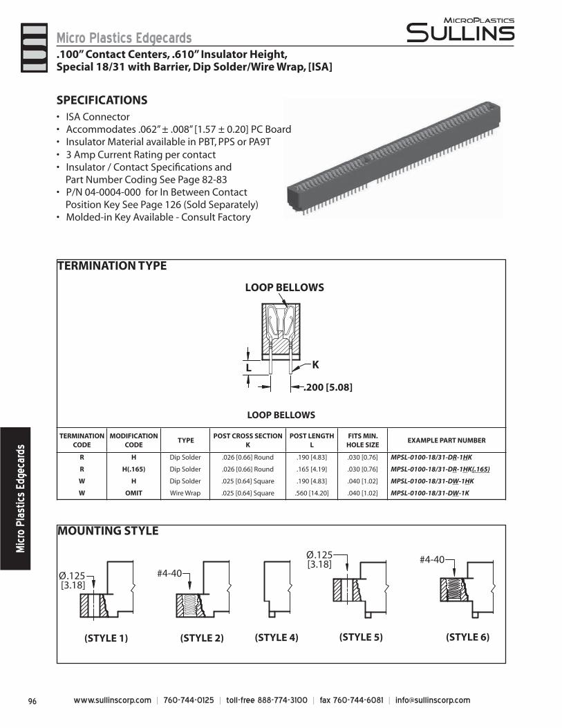
www.sullinscorp.com | 760-744-0125 | toll-free 888-774-3100 | fax 760-744-6081 | [email protected]
Micro Plastics EdgecardsM
icro
Pla
stic
s Ed
geca
rds
LOOP BELLOWS
TERMINATIONCODE
MODIFICATION CODE
TYPEPOST CROSS SECTION
KPOST LENGTH
LFITS MIN.
HOLE SIZEEXAMPLE PART NUMBER
R H Dip Solder .026 [0.66] Round .190 [4.83] .030 [0.76] MPSL-0100-18/31-DR-1HK
R H(.165) Dip Solder .026 [0.66] Round .165 [4.19] .030 [0.76] MPSL-0100-18/31-DR-1HK(.165)
W H Dip Solder .025 [0.64] Square .190 [4.83] .040 [1.02] MPSL-0100-18/31-DW-1HK
W OMIT Wire Wrap .025 [0.64] Square .560 [14.20] .040 [1.02] MPSL-0100-18/31-DW-1K
LOOP BELLOWS
KL
.200 [5.08]
MOUNTING STYLE
Ø.125 [3.18]
(STYLE 1) (STYLE 2)
#4-40
(STYLE 6)
#4-40
(STYLE 4) (STYLE 5)
Ø.125[3.18]
SPECIFICATIONSI• SA ConnectorAccommo• dates .062” ± .008” [1.57 ± 0.20] PC BoardInsulator Material available in PBT, PPS or PA9T• 3 Amp Current Rating • per contactInsulator / Contact Specifi cations and •
Part Number Coding See Page 82-83P/N 04-0004-000 for In Between Contact •
Position Key See Page 126 (Sold Separately)Molded-in Key Available - Consult Factory•
.100” Contact Centers, .610” Insulator Height,Special 18/31 with Barrier, Dip Solder/Wire Wrap, [ISA]
TERMINATION TYPE
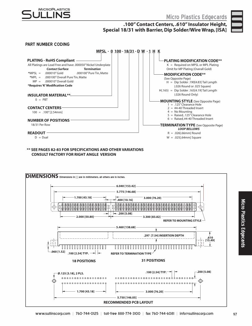
97www.sullinscorp.com | 760-744-0125 | toll-free 888-774-3100 | fax 760-744-6081 | [email protected]
Micro Plastics EdgecardsM
icro Plastics Edgecards
DIMENSIONS Dimensions in [ ] are in millimeters, all others are in inches.
.100 [2.54] TYP. REFER TO TERMINATION TYPE
.400 [10.16]
.200 [5.08]2.000 [50.80]
1.700 [43.18] 3.000 [76.20]
3.300 [83.82]
5.460 [138.68]
6.040 [153.42]
5.775 [146.68]
.297 [7.54] INSERTION DEPTH
REFER TO MOUNTING STYLE
18 POSITIONS 31 POSITIONS
.060 [1.52]
.100 [2.54] TYP. .200 [5.08]
1.700 [43.18] 3.000 [76.20]
RECOMMENDED PCB LAYOUT5.750 [146.05]
Ø.125 [3.18], 2 PLS.
.610[15.49]
1 = .125” Clearance Hole2 = #4-40 Threaded Insert4 = No Mounting5 = Raised, .125” Clearance Hole6 = Raised, #4-40 Threaded Insert
LOOP BELLOWSR = .026[.66mm] Round
W = .025[.64mm] Square
All Platings are Lead Free and have .000050” Nickel UnderplateContact Surface Termination
*MPSL = .000010” Gold .000100” Pure Tin, Matte*MPL = .000100” Overall Pure Tin, Matte
MP = .000010” Overall Gold *Requires ‘K’ Modifi cation Code
MODIFICATION CODE** (See Opposite Page)
MOUNTING STYLE (See Opposite Page)
TERMINATION TYPE (See Opposite Page)
H = Dip Solder .190[4.83] Tail Length(.026 Round or .025 Square)
H(.165) = Dip Solder .165[4.19] Tail Length(.026 Round Only)
CONTACT CENTERS100 = .100” [2.54mm]
NUMBER OF POSITIONS18/31 Per Row
INSULATOR MATERIAL**0 = PBT
READOUT
** SEE PAGES 82-83 FOR SPECIFICATIONS AND OTHER VARIATIONS CONSULT FACTORY FOR RIGHT ANGLE VERSION
K = Required on MPSL or MPL PlatingOmit for MP Plating (Overall Gold)
PLATING MODIFICATION CODE**
MPSL - 0 100 - 18/31 - D W - 1 H K
PART NUMBER CODING
.100” Contact Centers, .610” Insulator Height,Special 18/31 with Barrier, Dip Solder/Wire Wrap, [ISA]
D = Dual
PLATING - RoHS Compliant
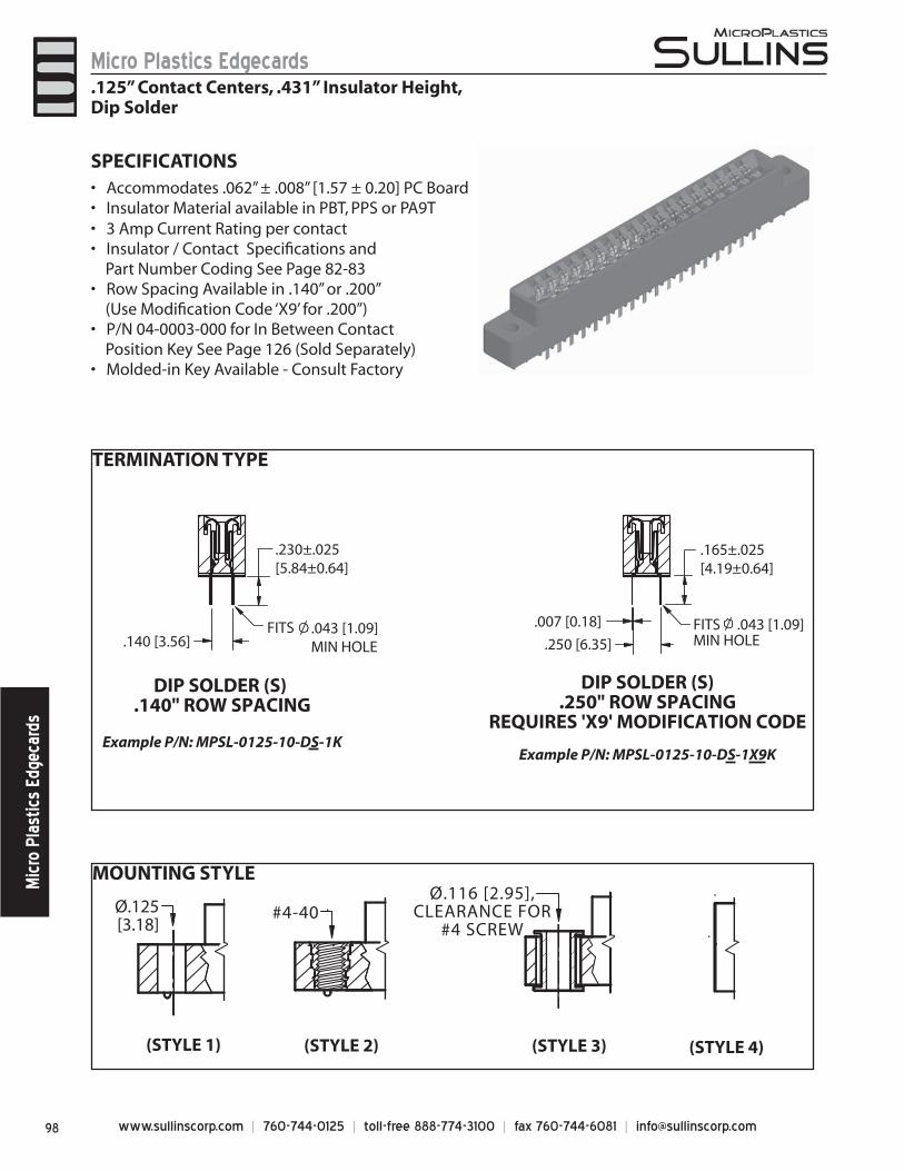
www.sullinscorp.com | 760-744-0125 | toll-free 888-774-3100 | fax 760-744-6081 | [email protected]
Micro Plastics EdgecardsM
icro
Pla
stic
s Ed
geca
rds
MOUNTING STYLE
TERMINATION TYPE
.165±.025 [4.19±0.64]
.250 [6.35]
.007 [0.18]
.230±.025 [5.84±0.64]
.140 [3.56]
DIP SOLDER (S) .140" ROW SPACING
Example P/N: MPSL-0125-10-DS-1K
DIP SOLDER (S).250" ROW SPACING
REQUIRES 'X9' MODIFICATION CODE
Example P/N: MPSL-0125-10-DS-1X9K
FITS .043 [1.09] MIN HOLE
FITS .043 [1.09] MIN HOLE
Ø.125[3.18]
#4-40
(STYLE 1) (STYLE 2) (STYLE 3) (STYLE 4)
Ø.116 [2.95],CLEARANCE FOR
#4 SCREW
SPECIFICATIONSAcc• ommodates .062” ± .008” [1.57 ± 0.20] PC BoardInsulator Material available in PBT, PPS or PA9T• 3 Amp Current Rating • per contactInsulator / Contact Specifi cations and •
Part Number Coding See Page 82-83Row Spacing Available in .140” or .200” •
(Use Modifi cation Code ‘X9’ for .200”)P/N 04-0003-000 for In Between Contact •
Position Key See Page 126 (Sold Separately) Molded-in Key Available - Consult Factory•
.125” Contact Centers, .431” Insulator Height,Dip Solder
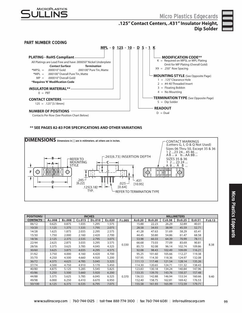
99www.sullinscorp.com | 760-744-0125 | toll-free 888-774-3100 | fax 760-744-6081 | [email protected]
Micro Plastics EdgecardsM
icro Plastics Edgecards
DIMENSIONS Dimensions in [ ] are in millimeters, all others are in inches.
POSITIONS/CONTACTS
INCHES MILLIMETERSA±.008 B±.008 C±.015 D±.010 E±.020 F±.005 A±0.20 B±0.20 C±0.38 D±0.25 E±0.51 F±0.13
06/12 0.625 0.875 1.035 1.295 1.575
0.330
15.88 22.23 26.29 32.89 40.01
8.38
10/20 1.125 1.375 1.535 1.795 2.075 28.58 34.93 38.99 45.59 52.7114/28 1.625 1.875 2.035 2.295 2.575 41.28 47.63 51.69 58.29 65.4115/30 1.750 2.000 2.160 2.420 2.700 44.45 50.80 54.86 61.47 68.5818/36 2.125 2.375 2.535 2.795 3.075 53.98 60.33 64.39 70.99 78.1122/44 2.625 2.875 3.035 3.295 3.575 66.68 73.03 77.09 83.69 90.8128/56 3.375 3.625 3.785 4.045 4.325 85.73 92.08 96.14 102.74 109.8630/60 3.625 3.875 4.035 4.295 4.575 92.08 98.43 102.49 109.09 116.2131/62 3.750 4.000 4.160 4.420 4.700 95.25 101.60 105.66 112.27 119.3835/70 4.250 4.500 4.660 4.920 5.200 107.95 114.30 118.36 124.97 132.0836/72 4.375 4.625 4.785 5.045 5.325 111.13 117.48 121.54 128.14 135.2637/74 4.500 4.750 4.910 5.170 5.450 114.30 120.65 124.71 131.32 138.4340/80 4.875 5.125 5.285 5.545 5.825
0.370
123.83 130.18 134.24 140.84 147.96
9.4043/86 5.250 5.500 5.660 5.920 6.200 133.35 139.70 143.76 150.37 157.4844/88 5.375 5.625 5.785 6.045 6.325 136.53 142.88 146.94 153.54 160.6649/98 6.000 6.250 6.410 6.670 6.950 152.40 158.75 162.81 169.42 176.5350/100 6.125 6.375 6.535 6.795 7.075 155.58 161.93 165.99 172.59 179.71
A
D
B
E
F 1 2 49 50
A B EE FF
CREFER TOMOUNTINGSTYLE
.125[3.18] TYP.
.265[6.73] INSERTION DEPTH
.431[10.95]
.245[6.22] .025
[0.64]
CONTACT MARKINGS(Letters G, I, O & Q Not Used)Sizes 06 Thru 50, Except 35 & 361 2 ...23 24... 45 46 ...
SIZES 35 & 361 2 ... 23 24 ... _
... ...
A B ... ... ...a b AA BB
A B A B_
REFER TO TERMINATION TYPE
S = Dip Solder
All Platings are Lead Free and have .000050” Nickel UnderplateContact Surface Termination
*MPSL = .000010” Gold .000100” Pure Tin, Matte*MPL = .000100” Overall Pure Tin, Matte
MP = .000010” Overall Gold *Requires ‘K’ Modifi cation Code
K = Required on MPSL or MPL PlatingOmit for MP Plating (Overall Gold)
X9 = .250” Row Spacing
MODIFICATION CODE**
TERMINATION TYPE (See Opposite Page)CONTACT CENTERS125 = .125” [3.18mm]
NUMBER OF POSITIONSContacts Per Row (See Position Chart Below)
INSULATOR MATERIAL**0 = PBT
READOUT
** SEE PAGES 82-83 FOR SPECIFICATIONS AND OTHER VARIATIONS
1 = .125” Clearance Hole2 = #4-40 Threaded Insert3 = Floating Bobbin
4 = No Mounting
MOUNTING STYLE (See Opposite Page)
MPL - 0 125 - 10 - D S - 1 KPART NUMBER CODING
.125” Contact Centers, .431” Insulator Height,Dip Solder
D = Dual
PLATING - RoHS Compliant
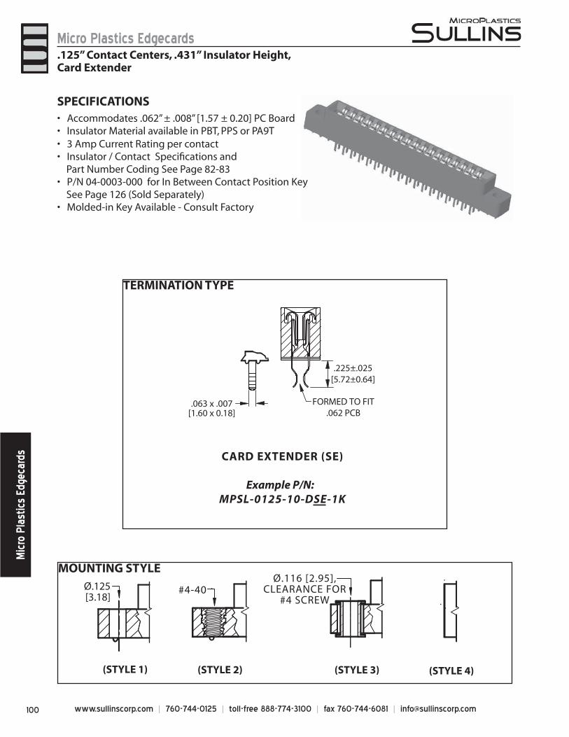
www.sullinscorp.com | 760-744-0125 | toll-free 888-774-3100 | fax 760-744-6081 | [email protected]
Micro Plastics EdgecardsM
icro
Pla
stic
s Ed
geca
rds
SPECIFICATIONSAcc• ommodates .062” ± .008” [1.57 ± 0.20] PC BoardInsulator Material available in PBT, PPS or PA9T• 3 Amp Current Rating • per contactInsulator / Contact Specifi cations and •
Part Number Coding See Page 82-83P/N 04-0003-000 for In Between Contact Position Key •
See Page 126 (Sold Separately) Molded-in Key Available - Consult Factory•
MOUNTING STYLE
TERMINATION TYPE
.225±.025[5.72±0.64]
FORMED TO FIT.062 PCB
CARD EXTENDER (SE)
Example P/N: MPSL-0125-10-DSE-1K
.063 x .007[1.60 x 0.18]
Ø.125[3.18]
#4-40
(STYLE 1) (STYLE 2) (STYLE 3) (STYLE 4)
Ø.116 [2.95],CLEARANCE FOR
#4 SCREW
.125” Contact Centers, .431” Insulator Height,Card Extender
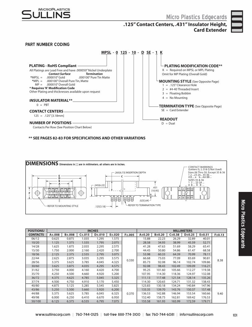
101www.sullinscorp.com | 760-744-0125 | toll-free 888-774-3100 | fax 760-744-6081 | [email protected]
Micro Plastics EdgecardsM
icro Plastics Edgecards
DIMENSIONS Dimensions in [ ] are in millimeters, all others are in inches.
POSITIONS/CONTACTS
INCHES MILLIMETERSA±.008 B±.008 C±.015 D±.010 E±.020 F±.005 A±0.20 B±0.20 C±0.38 D±0.25 E±0.51 F±0.13
06/12 0.625 0.875 1.035 1.295 1.575
0.330
15.88 22.23 26.29 32.89 40.01
8.38
10/20 1.125 1.375 1.535 1.795 2.075 28.58 34.93 38.99 45.59 52.7114/28 1.625 1.875 2.035 2.295 2.575 41.28 47.63 51.69 58.29 65.4115/30 1.750 2.000 2.160 2.420 2.700 44.45 50.80 54.86 61.47 68.5818/36 2.125 2.375 2.535 2.795 3.075 53.98 60.33 64.39 70.99 78.1122/44 2.625 2.875 3.035 3.295 3.575 66.68 73.03 77.09 83.69 90.8128/56 3.375 3.625 3.785 4.045 4.325 85.73 92.08 96.14 102.74 109.8630/60 3.625 3.875 4.035 4.295 4.575 92.08 98.43 102.49 109.09 116.2131/62 3.750 4.000 4.160 4.420 4.700 95.25 101.60 105.66 112.27 119.3835/70 4.250 4.500 4.660 4.920 5.200 107.95 114.30 118.36 124.97 132.0836/72 4.375 4.625 4.785 5.045 5.325 111.13 117.48 121.54 128.14 135.2637/74 4.500 4.750 4.910 5.170 5.450 114.30 120.65 124.71 131.32 138.4340/80 4.875 5.125 5.285 5.545 5.825
0.370
123.83 130.18 134.24 140.84 147.96
9.4043/86 5.250 5.500 5.660 5.920 6.200 133.35 139.70 143.76 150.37 157.4844/88 5.375 5.625 5.785 6.045 6.325 136.53 142.88 146.94 153.54 160.6649/98 6.000 6.250 6.410 6.670 6.950 152.40 158.75 162.81 169.42 176.5350/100 6.125 6.375 6.535 6.795 7.075 155.58 161.93 165.99 172.59 179.71
C
.025[.64]
.245[6.22].431
[10.95]
.125[3.18]
BA
DE
.265[6.73] INSERTION DEPTH
REFER TO TERMINATION TYPE
F
1 2 49 50
A B EE FF
REFER TO MOUNTING STYLE
CONTACT MARKINGS(Letters G, I, O & Q Not Used)Sizes 06 Thru 50, Except 35 & 361 2 ...23 24... 45 46 ...
SIZES 35 & 361 2 ... 23 24 ... _
... ...
A B ... ... ...a b AA BB
A B A B_
PART NUMBER CODING
.125” Contact Centers, .431” Insulator Height,Card Extender
CONTACT CENTERS125 = .125” [3.18mm]
NUMBER OF POSITIONSContacts Per Row (See Position Chart Below)
1 = .125” Clearance Hole2 = #4-40 Threaded Insert3 = Floating Bobbin
4 = No Mounting INSULATOR MATERIAL**
0 = PBT
K = Required on MPSL or MPL PlatingOmit for MP Plating (Overall Gold)
PLATING MODIFICATION CODE**
MOUNTING STYLE (See Opposite Page)
TERMINATION TYPE (See Opposite Page)
READOUT
** SEE PAGES 82-83 FOR SPECIFICATIONS AND OTHER VARIATIONS
SE = Card Extender
All Platings are Lead Free and have .000050” Nickel UnderplateContact Surface Termination
*MPSL = .000010” Gold .000100” Pure Tin Matte*MPL = .000100” Overall Pure Tin, Matte
MP = .000010” Overall Gold* Requires ‘K’ Modifi cation CodeOther Plating and thicknesses available upon request
MPSL - 0 125 - 10 - D SE - 1 K
D = Dual
PLATING - RoHS Compliant
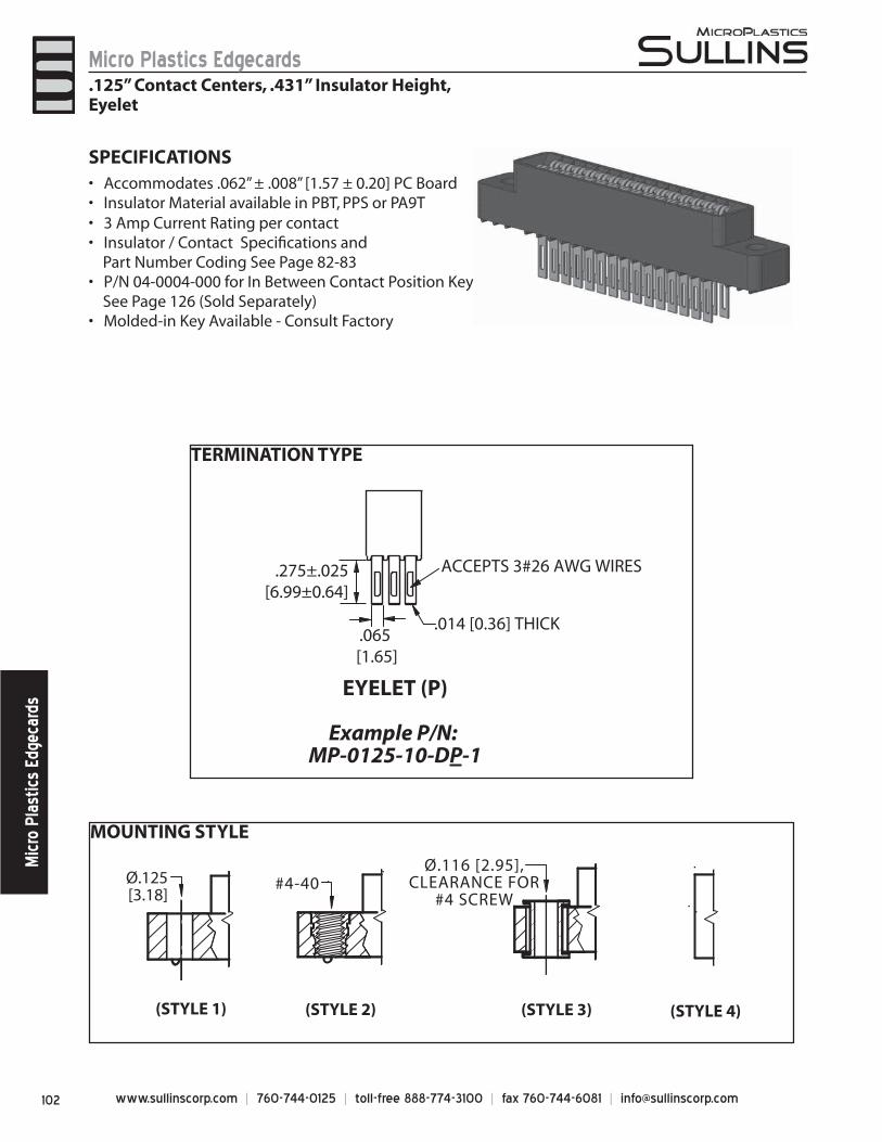
www.sullinscorp.com | 760-744-0125 | toll-free 888-774-3100 | fax 760-744-6081 | [email protected]
Micro Plastics EdgecardsM
icro
Pla
stic
s Ed
geca
rds
SPECIFICATIONSAcc• ommodates .062” ± .008” [1.57 ± 0.20] PC BoardInsulator Material available in PBT, PPS or PA9T• 3 Amp Current Rating • per contactInsulator / Contact Specifi cations and •
Part Number Coding See Page 82-83P/N 04-0004-000 for In Between Contact Position Key •
See Page 126 (Sold Separately) Molded-in Key Available - Consult Factory•
TERMINATION TYPE
MOUNTING STYLE
Ø.125[3.18]
#4-40
(STYLE 1) (STYLE 2) (STYLE 3) (STYLE 4)
Ø.116 [2.95],CLEARANCE FOR
#4 SCREW
EYELET (P)
Example P/N: MP-0125-10-DP-1
.065 [1.65]
.275±.025[6.99±0.64]
ACCEPTS 3#26 AWG WIRES
.014 [0.36] THICK
.125” Contact Centers, .431” Insulator Height,Eyelet
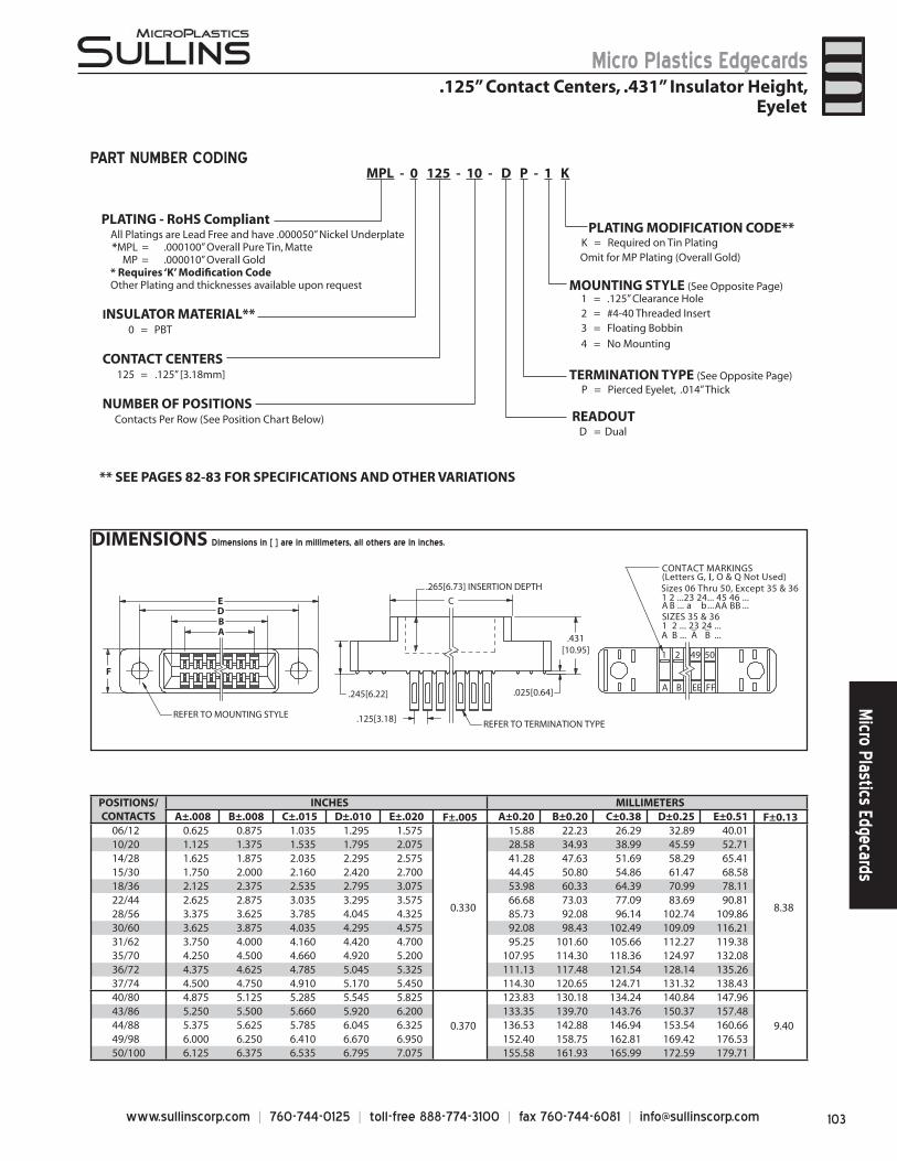
103www.sullinscorp.com | 760-744-0125 | toll-free 888-774-3100 | fax 760-744-6081 | [email protected]
Micro Plastics EdgecardsM
icro Plastics Edgecards
DIMENSIONS Dimensions in [ ] are in millimeters, all others are in inches.
POSITIONS/CONTACTS
INCHES MILLIMETERSA±.008 B±.008 C±.015 D±.010 E±.020 F±.005 A±0.20 B±0.20 C±0.38 D±0.25 E±0.51 F±0.13
06/12 0.625 0.875 1.035 1.295 1.575
0.330
15.88 22.23 26.29 32.89 40.01
8.38
10/20 1.125 1.375 1.535 1.795 2.075 28.58 34.93 38.99 45.59 52.7114/28 1.625 1.875 2.035 2.295 2.575 41.28 47.63 51.69 58.29 65.4115/30 1.750 2.000 2.160 2.420 2.700 44.45 50.80 54.86 61.47 68.5818/36 2.125 2.375 2.535 2.795 3.075 53.98 60.33 64.39 70.99 78.1122/44 2.625 2.875 3.035 3.295 3.575 66.68 73.03 77.09 83.69 90.8128/56 3.375 3.625 3.785 4.045 4.325 85.73 92.08 96.14 102.74 109.8630/60 3.625 3.875 4.035 4.295 4.575 92.08 98.43 102.49 109.09 116.2131/62 3.750 4.000 4.160 4.420 4.700 95.25 101.60 105.66 112.27 119.3835/70 4.250 4.500 4.660 4.920 5.200 107.95 114.30 118.36 124.97 132.0836/72 4.375 4.625 4.785 5.045 5.325 111.13 117.48 121.54 128.14 135.2637/74 4.500 4.750 4.910 5.170 5.450 114.30 120.65 124.71 131.32 138.4340/80 4.875 5.125 5.285 5.545 5.825
0.370
123.83 130.18 134.24 140.84 147.96
9.4043/86 5.250 5.500 5.660 5.920 6.200 133.35 139.70 143.76 150.37 157.4844/88 5.375 5.625 5.785 6.045 6.325 136.53 142.88 146.94 153.54 160.6649/98 6.000 6.250 6.410 6.670 6.950 152.40 158.75 162.81 169.42 176.5350/100 6.125 6.375 6.535 6.795 7.075 155.58 161.93 165.99 172.59 179.71
C
.245[6.22]
.431[10.95]
.025[0.64]
EDB
.125[3.18]
A
REFER TO MOUNTING STYLE
F
.265[6.73] INSERTION DEPTH
REFER TO TERMINATION TYPE
1 2 49 50
A B EE FF
CONTACT MARKINGS(Letters G, I, O & Q Not Used)Sizes 06 Thru 50, Except 35 & 361 2 ...23 24... 45 46 ...
SIZES 35 & 361 2 ... 23 24 ... _
... ...
A B ... ... ...a b AA BB
A B A B_
CONTACT CENTERS125 = .125” [3.18mm]
NUMBER OF POSITIONSContacts Per Row (See Position Chart Below)
1 = .125” Clearance Hole2 = #4-40 Threaded Insert3 = Floating Bobbin
4 = No Mounting
P = Pierced Eyelet, .014” Thick
INSULATOR MATERIAL**0 = PBT
PLATING MODIFICATION CODE**
MOUNTING STYLE (See Opposite Page)
TERMINATION TYPE (See Opposite Page)
READOUT
** SEE PAGES 82-83 FOR SPECIFICATIONS AND OTHER VARIATIONS
K = Required on Tin PlatingOmit for MP Plating (Overall Gold)
All Platings are Lead Free and have .000050” Nickel Underplate*MPL = .000100” Overall Pure Tin, Matte
MP = .000010” Overall Gold* Requires ‘K’ Modifi cation CodeOther Plating and thicknesses available upon request
MPL - 0 125 - 10 - D P - 1 K PART NUMBER CODING
.125” Contact Centers, .431” Insulator Height,Eyelet
D = Dual
PLATING - RoHS Compliant
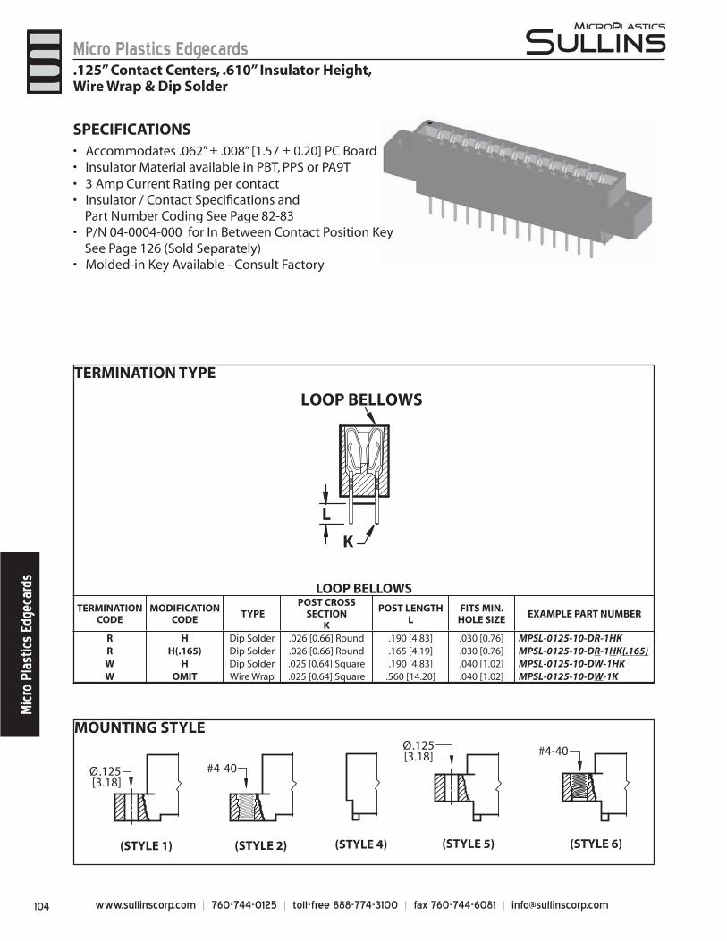
www.sullinscorp.com | 760-744-0125 | toll-free 888-774-3100 | fax 760-744-6081 | [email protected]
Micro Plastics EdgecardsM
icro
Pla
stic
s Ed
geca
rds
MOUNTING STYLE
LOOP BELLOWSTERMINATION
CODEMODIFICATION
CODE TYPE
POST CROSS SECTION
K
POST LENGTH L
FITS MIN.HOLE SIZE
EXAMPLE PART NUMBER
R H Dip Solder .026 [0.66] Round .190 [4.83] .030 [0.76] MPSL-0125-10-DR-1HKR H(.165) Dip Solder .026 [0.66] Round .165 [4.19] .030 [0.76] MPSL-0125-10-DR-1HK(.165)W H Dip Solder .025 [0.64] Square .190 [4.83] .040 [1.02] MPSL-0125-10-DW-1HKW OMIT Wire Wrap .025 [0.64] Square .560 [14.20] .040 [1.02] MPSL-0125-10-DW-1K
Ø.125 [3.18]
(STYLE 1) (STYLE 2)
#4-40
(STYLE 6)
#4-40
(STYLE 4) (STYLE 5)
Ø.125[3.18]
LOOP BELLOWS
K
L
SPECIFICATIONSAccommo• dates .062” ± .008” [1.57 ± 0.20] PC BoardInsulator Material available in PBT, PPS or PA9T• 3 Amp Current Rating • per contactInsulator / Contact Specifi cations and •
Part Number Coding See Page 82-83P/N 04-0004-000 for In Between Contact Position Key •
See Page 126 (Sold Separately)Molded-in Key Available - Consult Factory•
.125” Contact Centers, .610” Insulator Height,Wire Wrap & Dip Solder
TERMINATION TYPE
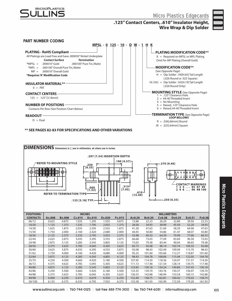
105www.sullinscorp.com | 760-744-0125 | toll-free 888-774-3100 | fax 760-744-6081 | [email protected]
Micro Plastics EdgecardsM
icro Plastics Edgecards
DIMENSIONS Dimensions in [ ] are in millimeters, all others are in inches.
1 3 5 95 97 992 4 6 96 98 100
.370 [9.40]
AB
C
DE
F.125 [3.18] TYP.
[1.52].060
[6.35].250
.610[15.49]
.180 [4.57]
[7.95].313
.297 [7.54] INSERTION DEPTH
REFER TO MOUNTING STYLE
.250 [6.35]
REFER TO TERMINATION TYPE
CONTACT MARKINGS1 3 5 . . . 95 97 992 4 6 . . . 96 98 100
1 = .125” Clearance Hole2 = #4-40 Threaded Insert4 = No Mounting5 = Raised, .125” Clearance Hole6 = Raised, #4-40 Threaded Insert
LOOP BELLOWSR = .026[.66mm] Round
W = .025[.64mm] Square
All Platings are Lead Free and have .000050” Nickel UnderplateContact Surface Termination
*MPSL = .000010” Gold .000100” Pure Tin, Matte*MPL = .000100” Overall Pure Tin, Matte
MP = .000010” Overall Gold *Requires ‘K’ Modifi cation Code
MODIFICATION CODE**(See Opposite Page)
MOUNTING STYLE (See Opposite Page)
TERMINATION TYPE (See Opposite Page)
H = Dip Solder .190[4.83] Tail Length(.026 Round or .025 Square)
H(.165) = Dip Solder .165[4.19] Tail Length(.026 Round Only)
CONTACT CENTERS125 = .125” [3.18mm]
NUMBER OF POSITIONSContacts Per Row (See Position Chart Below)
INSULATOR MATERIAL**0 = PBT
READOUT
** SEE PAGES 82-83 FOR SPECIFICATIONS AND OTHER VARIATIONS
K = Required on MPSL or MPL PlatingOmit for MP Plating (Overall Gold)
PLATING MODIFICATION CODE**
MPSL - 0 125 - 10 - D W - 1 H KPART NUMBER CODING
.125” Contact Centers, .610” Insulator Height,Wire Wrap & Dip Solder
POSITIONS/CONTACTS
INCHES MILLIMETERSA±.008 B±.008 C±.015 D±.010 E±.020 F±.015 A±0.20 B±0.20 C±0.38 D±0.25 E±0.51 F±0.38
06/12 0.625 0.875 1.035 1.295 1.555 0.875 15.88 22.23 26.29 32.89 39.50 22.2310/20 1.125 1.375 1.535 1.795 2.055 1.375 28.58 34.93 38.99 45.59 52.20 34.9314/28 1.625 1.875 2.035 2.295 2.555 1.875 41.28 47.63 51.69 58.29 64.90 47.6315/30 1.750 2.000 2.160 2.420 2.680 2.000 44.45 50.80 54.86 61.47 68.07 50.8018/36 2.125 2.375 2.535 2.795 3.055 2.375 53.98 60.33 64.39 70.99 77.60 60.3322/44 2.625 2.875 3.035 3.295 3.555 2.875 66.68 73.03 77.09 83.69 90.30 73.0324/48 2.875 3.125 3.285 3.545 3.805 3.125 73.03 79.38 83.44 90.04 96.65 79.3828/56 3.375 3.625 3.785 4.045 4.305 3.625 85.73 92.08 96.14 102.74 109.35 92.0830/60 3.625 3.875 4.035 4.295 4.555 3.875 92.08 98.43 102.49 109.09 115.70 98.4331/62 3.750 4.000 4.160 4.420 4.680 4.000 95.25 101.60 105.66 112.27 118.87 101.6032/64 3.875 4.125 4.285 4.545 4.805 4.125 98.43 104.78 108.84 115.44 122.05 104.7835/70 4.250 4.500 4.660 4.920 5.180 4.500 107.95 114.30 118.36 124.97 131.57 114.3036/72 4.375 4.625 4.785 5.045 5.305 4.625 111.13 117.48 121.54 128.14 134.75 117.4840/80 4.875 5.125 5.285 5.545 5.805 5.125 123.83 130.18 134.24 140.84 147.45 130.1843/86 5.250 5.500 5.660 5.920 6.180 5.500 133.35 139.70 143.76 150.37 156.97 139.7044/88 5.375 5.625 5.785 6.045 6.305 5.625 136.53 142.88 146.94 153.54 160.15 142.8849/98 6.000 6.250 6.410 6.670 6.930 6.250 152.40 158.75 162.81 169.42 176.02 158.7550/100 6.125 6.375 6.535 6.795 7.055 6.375 155.58 161.93 165.99 172.59 179.20 161.93
D = Dual
PLATING - RoHS Compliant
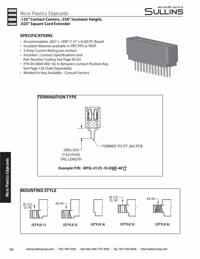
www.sullinscorp.com | 760-744-0125 | toll-free 888-774-3100 | fax 760-744-6081 | [email protected]
Micro Plastics EdgecardsM
icro
Pla
stic
s Ed
geca
rds
MOUNTING STYLE
Ø.125 [3.18]
(STYLE 1) (STYLE 2)
#4-40
(STYLE 6)
#4-40
(STYLE 4) (STYLE 5)
Ø.125[3.18]
TERMINATION TYPE
FORMED TO FIT .062 PCB.300±.025
[7.62±0.64]TAIL LENGTH
Example P/N: MPSL-0125-10-DWE-4KTT
SPECIFICATIONSAccommo• dates .062” ± .008” [1.57 ± 0.20] PC BoardInsulator Material available in PBT, PPS or PA9T• 3 Amp Current Rating • per contactInsulator / Contact Specifi cations and •
Part Number Coding See Page 82-83P/N 04-0004-000 for In Between Contact Position Key •
See Page 126 (Sold Separately)Molded-in Key Available - Consult Factory•
.125” Contact Centers, .550” Insulator Height,
.025” Square Card Extender
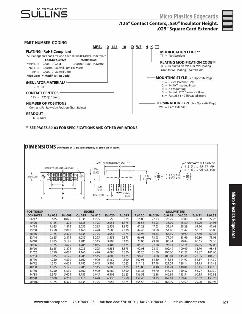
107www.sullinscorp.com | 760-744-0125 | toll-free 888-774-3100 | fax 760-744-6081 | [email protected]
Micro Plastics EdgecardsM
icro Plastics Edgecards
DIMENSIONS Dimensions in [ ] are in millimeters, all others are in inches.
POSITIONS/CONTACTS
INCHES MILLIMETERSA±.008 B±.008 C±.015 D±.010 E±.020 F±.015 A±0.20 B±0.20 C±0.38 D±0.25 E±0.51 F±0.38
06/12 0.625 0.875 1.035 1.295 1.555 0.875 15.88 22.23 26.29 32.89 39.50 22.2310/20 1.125 1.375 1.535 1.795 2.055 1.375 28.58 34.93 38.99 45.59 52.20 34.9314/28 1.625 1.875 2.035 2.295 2.555 1.875 41.28 47.63 51.69 58.29 64.90 47.6315/30 1.750 2.000 2.160 2.420 2.680 2.000 44.45 50.80 54.86 61.47 68.07 50.8018/36 2.125 2.375 2.535 2.795 3.055 2.375 53.98 60.33 64.39 70.99 77.60 60.3322/44 2.625 2.875 3.035 3.295 3.555 2.875 66.68 73.03 77.09 83.69 90.30 73.0324/48 2.875 3.125 3.285 3.545 3.805 3.125 73.03 79.38 83.44 90.04 96.65 79.3828/56 3.375 3.625 3.785 4.045 4.305 3.625 85.73 92.08 96.14 102.74 109.35 92.0830/60 3.625 3.875 4.035 4.295 4.555 3.875 92.08 98.43 102.49 109.09 115.70 98.4331/62 3.750 4.000 4.160 4.420 4.680 4.000 95.25 101.60 105.66 112.27 118.87 101.6032/64 3.875 4.125 4.285 4.545 4.805 4.125 98.43 104.78 108.84 115.44 122.05 104.7835/70 4.250 4.500 4.660 4.920 5.180 4.500 107.95 114.30 118.36 124.97 131.57 114.3036/72 4.375 4.625 4.785 5.045 5.305 4.625 111.13 117.48 121.54 128.14 134.75 117.4840/80 4.875 5.125 5.285 5.545 5.805 5.125 123.83 130.18 134.24 140.84 147.45 130.1843/86 5.250 5.500 5.660 5.920 6.180 5.500 133.35 139.70 143.76 150.37 156.97 139.7044/88 5.375 5.625 5.785 6.045 6.305 5.625 136.53 142.88 146.94 153.54 160.15 142.8849/98 6.000 6.250 6.410 6.670 6.930 6.250 152.40 158.75 162.81 169.42 176.02 158.7550/100 6.125 6.375 6.535 6.795 7.055 6.375 155.58 161.93 165.99 172.59 179.20 161.93
.250[6.35]
.550[13.97]
.025[0.64]
F
C
.120[3.05]
E
D
B
.125 [3.18]
A
.370 [9.40]
REFER TO MOUNTING STYLE
.297 [7.54] INSERTION DEPTH
1 3 5 95 97 99
2 4 6 96 98 100
CONTACT MARKINGS1 3 5 . . . 95 97 992 4 6 . . . 96 98 100
1 = .125” Clearance Hole2 = #4-40 Threaded Insert4 = No Mounting5 = Raised, .125” Clearance Hole6 = Raised, #4-40 Threaded Insert
All Platings are Lead Free and have .000050” Nickel UnderplateContact Surface Termination
*MPSL = .000010” Gold .000100” Pure Tin, Matte*MPL = .000100” Overall Pure Tin, Matte
MP = .000010” Overall Gold *Requires ‘K’ Modifi cation Code
MOUNTING STYLE (See Opposite Page)
TERMINATION TYPE (See Opposite Page)
TT = No Standoffs
WE = Card Extender
CONTACT CENTERS125 = .125” [3.18mm]
NUMBER OF POSITIONSContacts Per Row (See Position Chart Below)
INSULATOR MATERIAL**0 = PBT
READOUT
** SEE PAGES 80-83 FOR SPECIFICATIONS AND OTHER VARIATIONS
K = Required on MPSL or MPL PlatingOmit for MP Plating (Overall Gold)
PLATING MODIFICATION CODE**
MODIFICATION CODE**MPSL - 0 125 - 10 - D WE - 4 K TT
PART NUMBER CODING
.125” Contact Centers, .550” Insulator Height,.025” Square Card Extender
D = Dual
PLATING - RoHS Compliant
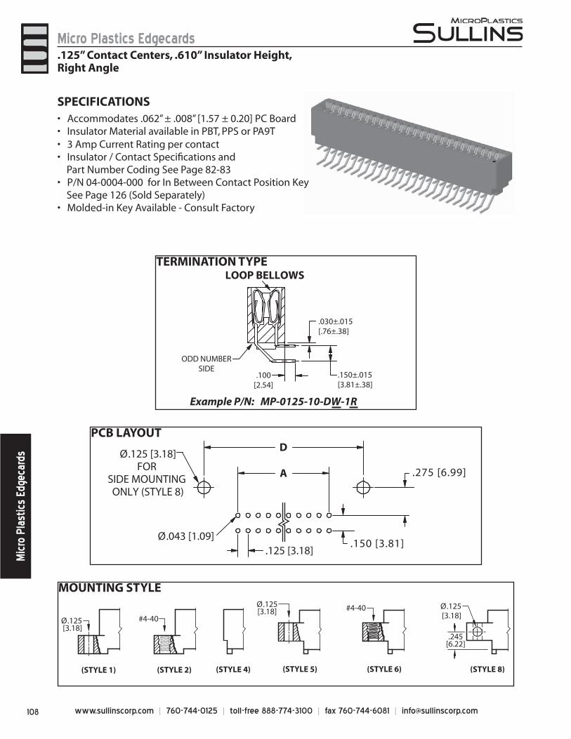
www.sullinscorp.com | 760-744-0125 | toll-free 888-774-3100 | fax 760-744-6081 | [email protected]
Micro Plastics EdgecardsM
icro
Pla
stic
s Ed
geca
rds
MOUNTING STYLE
TERMINATION TYPE
PCB LAYOUT
.125 [3.18]
A
DØ.125 [3.18]
FOR SIDE MOUNTING ONLY (STYLE 8)
Ø.043 [1.09].150 [3.81]
.275 [6.99]
.030±.015[.76±.38]
.150±.015[3.81±.38]
ODD NUMBERSIDE
LOOP BELLOWS
Example P/N: MP-0125-10-DW-1R
.100[2.54]
SPECIFICATIONSAccommo• dates .062” ± .008” [1.57 ± 0.20] PC BoardInsulator Material available in PBT, PPS or PA9T• 3 Amp Current Rating • per contactInsulator / Contact Specifi cations and •
Part Number Coding See Page 82-83P/N 04-0004-000 for In Between Contact Position Key •
See Page 126 (Sold Separately)Molded-in Key Available - Consult Factory•
.125” Contact Centers, .610” Insulator Height,Right Angle
(STYLE 8)
.245[6.22]
Ø.125[3.18]
Ø.125 [3.18]
(STYLE 1) (STYLE 2)
#4-40
(STYLE 6)
#4-40
(STYLE 4) (STYLE 5)
Ø.125[3.18]

109www.sullinscorp.com | 760-744-0125 | toll-free 888-774-3100 | fax 760-744-6081 | [email protected]
Micro Plastics EdgecardsM
icro Plastics Edgecards
DIMENSIONS Dimensions in [ ] are in millimeters, all others are in inches.
1 = .125” Clearance Hole2 = #4-40 Threaded Insert4 = No Mounting5 = Raised, .125” Clearance Hole6 = Raised, #4-40 Threaded Insert8 = Raised, Side Mounting,
.125” Clearance Hole
LOOP BELLOWSW = .025 [.64] Square
All Platings are Lead Free and have .000050” Nickel UnderplateContact Surface Termination
*MPSL = .000010” Gold .000100” Pure Tin, Matte*MPL = .000100” Overall Pure Tin, Matte
MP = .000010” Overall Gold *Requires ‘K’ Modifi cation Code MOUNTING STYLE (See Opposite Page)
TERMINATION TYPE (See Opposite Page)
R = Right Angle
MPSL - 0 125 - 10 - D W - 1 K R
CONTACT CENTERS125 = .125” [3018mm]
NUMBER OF POSITIONSContacts Per Row (See Position Chart Below)
INSULATOR MATERIAL**0 = PBT
READOUT
** SEE PAGES 82-83 FOR SPECIFICATIONS AND OTHER VARIATIONS
K = Required on MPSL or MPL PlatingOmit for MP Plating (Overall Gold)
MODIFICATION CODE**
PLATING MODIFICATION CODE**
C
.610[15.49]
.180[4.57]
.250[6.35]
.060[1.52]
F
.025[.64]
B
E
D
A
.125[3.18]
REFER TO MOUNTING STYLE
1 3 5 95 97 99
2 4 6 96 98 100
CONTACT MARKINGS1 3 5 . . . 95 97 992 4 6 . . . 96 98 100
.370[9.40]
.297 [7.54] INSERTION DEPTH
.125 [3.18]
PART NUMBER CODING
.125” Contact Centers, .610” Insulator Height,Right Angle
POSITIONS/CONTACTS
INCHES MILLIMETERSA±.008 B±.008 C±.015 D±.010 E±.020 F±.015 A±0.20 B±0.20 C±0.38 D±0.25 E±0.51 F±0.38
06/12 0.625 0.875 1.035 1.295 1.555 0.875 15.88 22.23 26.29 32.89 39.50 22.2310/20 1.125 1.375 1.535 1.795 2.055 1.375 28.58 34.93 38.99 45.59 52.20 34.9314/28 1.625 1.875 2.035 2.295 2.555 1.875 41.28 47.63 51.69 58.29 64.90 47.6315/30 1.750 2.000 2.160 2.420 2.680 2.000 44.45 50.80 54.86 61.47 68.07 50.8018/36 2.125 2.375 2.535 2.795 3.055 2.375 53.98 60.33 64.39 70.99 77.60 60.3322/44 2.625 2.875 3.035 3.295 3.555 2.875 66.68 73.03 77.09 83.69 90.30 73.0324/48 2.875 3.125 3.285 3.545 3.805 3.125 73.03 79.38 83.44 90.04 96.65 79.3828/56 3.375 3.625 3.785 4.045 4.305 3.625 85.73 92.08 96.14 102.74 109.35 92.0830/60 3.625 3.875 4.035 4.295 4.555 3.875 92.08 98.43 102.49 109.09 115.70 98.4331/62 3.750 4.000 4.160 4.420 4.680 4.000 95.25 101.60 105.66 112.27 118.87 101.6032/64 3.875 4.125 4.285 4.545 4.805 4.125 98.43 104.78 108.84 115.44 122.05 104.7835/70 4.250 4.500 4.660 4.920 5.180 4.500 107.95 114.30 118.36 124.97 131.57 114.3036/72 4.375 4.625 4.785 5.045 5.305 4.625 111.13 117.48 121.54 128.14 134.75 117.4840/80 4.875 5.125 5.285 5.545 5.805 5.125 123.83 130.18 134.24 140.84 147.45 130.1843/86 5.250 5.500 5.660 5.920 6.180 5.500 133.35 139.70 143.76 150.37 156.97 139.7044/88 5.375 5.625 5.785 6.045 6.305 5.625 136.53 142.88 146.94 153.54 160.15 142.8849/98 6.000 6.250 6.410 6.670 6.930 6.250 152.40 158.75 162.81 169.42 176.02 158.7550/100 6.125 6.375 6.535 6.795 7.055 6.375 155.58 161.93 165.99 172.59 179.20 161.93
D = Dual
PLATING - RoHS Compliant
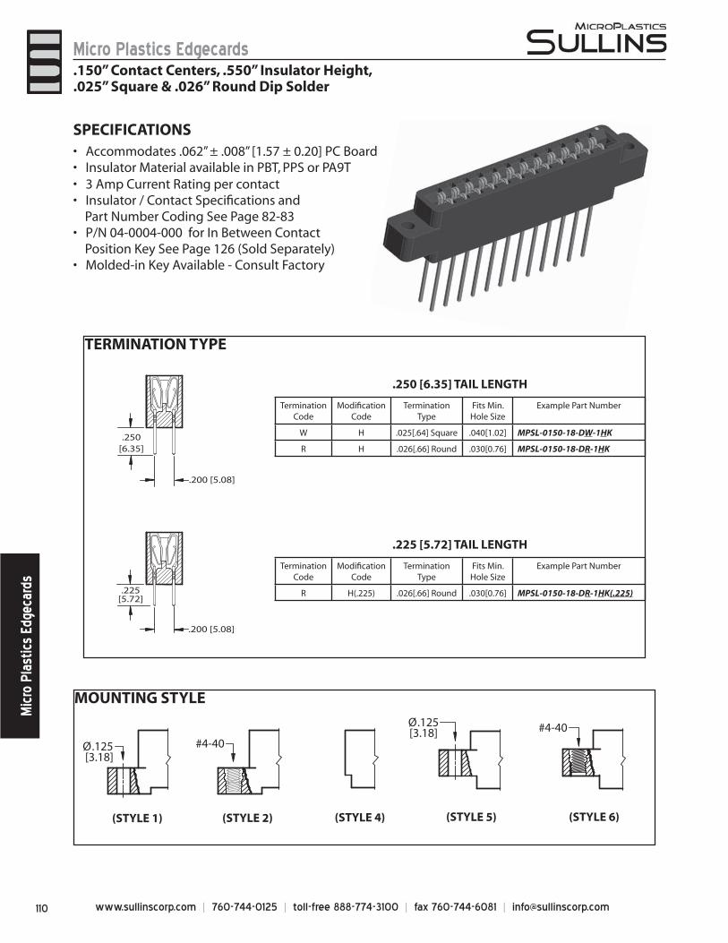
www.sullinscorp.com | 760-744-0125 | toll-free 888-774-3100 | fax 760-744-6081 | [email protected]
Micro Plastics EdgecardsM
icro
Pla
stic
s Ed
geca
rds
MOUNTING STYLE
Ø.125 [3.18]
(STYLE 1) (STYLE 2)
#4-40
(STYLE 6)
#4-40
(STYLE 4) (STYLE 5)
Ø.125[3.18]
TERMINATION TYPE
.250[6.35]
.225[5.72]
.200 [5.08]
.200 [5.08]
.225 [5.72] TAIL LENGTH
Termination Code
Modifi cation Code
TerminationType
Fits Min. Hole Size
Example Part Number
R H(.225) .026[.66] Round .030[0.76] MPSL-0150-18-DR-1HK(.225)
.250 [6.35] TAIL LENGTH
Termination Code
Modifi cation Code
TerminationType
Fits Min. Hole Size
Example Part Number
W H .025[.64] Square .040[1.02] MPSL-0150-18-DW-1HK
R H .026[.66] Round .030[0.76] MPSL-0150-18-DR-1HK
SPECIFICATIONSAccommo• dates .062” ± .008” [1.57 ± 0.20] PC BoardInsulator Material available in PBT, PPS or PA9T• 3 Amp Current Rating • per contactInsulator / Contact Specifi cations and •
Part Number Coding See Page 82-83P/N 04-0004-000 for In Between Contact •
Position Key See Page 126 (Sold Separately)Molded-in Key Available - Consult Factory•
.150” Contact Centers, .550” Insulator Height,
.025” Square & .026” Round Dip Solder
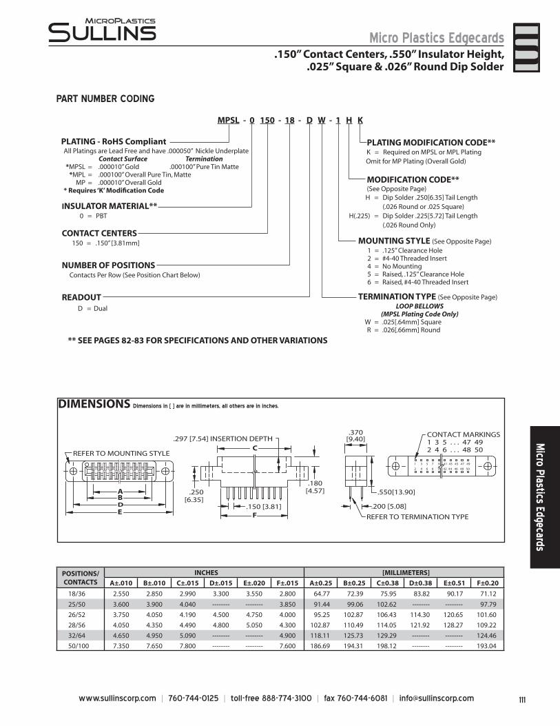
111www.sullinscorp.com | 760-744-0125 | toll-free 888-774-3100 | fax 760-744-6081 | [email protected]
Micro Plastics EdgecardsM
icro Plastics Edgecards
DIMENSIONS Dimensions in [ ] are in millimeters, all others are in inches.
1 3 5 7 9 41 43 45 47 49
2 4 6 8 10 42 44 46 48 50
AB
C
DE F
REFER TO MOUNTING STYLE
REFER TO TERMINATION TYPE
.297 [7.54] INSERTION DEPTH
.180[4.57].250
[6.35].150 [3.81]
.550[13.90]
.370[9.40]
.200 [5.08]
CONTACT MARKINGS1 3 5 . . . 47 492 4 6 . . . 48 50
POSITIONS/CONTACTS
INCHES [MILLIMETERS]
A±.010 B±.010 C±.015 D±.015 E±.020 F±.015 A±0.25 B±0.25 C±0.38 D±0.38 E±0.51 F±0.20
18/36 2.550 2.850 2.990 3.300 3.550 2.800 64.77 72.39 75.95 83.82 90.17 71.12
25/50 3.600 3.900 4.040 -------- -------- 3.850 91.44 99.06 102.62 -------- -------- 97.79
26/52 3.750 4.050 4.190 4.500 4.750 4.000 95.25 102.87 106.43 114.30 120.65 101.60
28/56 4.050 4.350 4.490 4.800 5.050 4.300 102.87 110.49 114.05 121.92 128.27 109.22
32/64 4.650 4.950 5.090 -------- -------- 4.900 118.11 125.73 129.29 -------- -------- 124.46
50/100 7.350 7.650 7.800 -------- -------- 7.600 186.69 194.31 198.12 -------- -------- 193.04
PART NUMBER CODING
.150” Contact Centers, .550” Insulator Height,.025” Square & .026” Round Dip Solder
1 = .125” Clearance Hole2 = #4-40 Threaded Insert4 = No Mounting5 = Raised, .125” Clearance Hole6 = Raised, #4-40 Threaded Insert
LOOP BELLOWS(MPSL Plating Code Only)
W = .025[.64mm] SquareR = .026[.66mm] Round
MODIFICATION CODE** (See Opposite Page)
MOUNTING STYLE (See Opposite Page)
TERMINATION TYPE (See Opposite Page)
H = Dip Solder .250[6.35] Tail Length(.026 Round or .025 Square)
H(.225) = Dip Solder .225[5.72] Tail Length(.026 Round Only)
CONTACT CENTERS150 = .150” [3.81mm]
NUMBER OF POSITIONSContacts Per Row (See Position Chart Below)
INSULATOR MATERIAL**0 = PBT
READOUT
** SEE PAGES 82-83 FOR SPECIFICATIONS AND OTHER VARIATIONS
K = Required on MPSL or MPL PlatingOmit for MP Plating (Overall Gold)
PLATING MODIFICATION CODE**
MPSL - 0 150 - 18 - D W - 1 H K
D = Dual
PLATING - RoHS CompliantAll Platings are Lead Free and have .000050” Nickle Underplate
Contact Surface Termination*MPSL = .000010” Gold .000100” Pure Tin Matte
*MPL = .000100” Overall Pure Tin, MatteMP = .000010” Overall Gold
* Requires ‘K’ Modifi cation Code
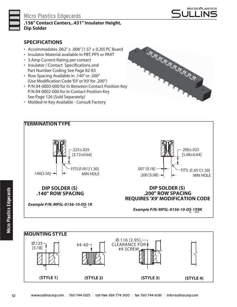
www.sullinscorp.com | 760-744-0125 | toll-free 888-774-3100 | fax 760-744-6081 | [email protected]
Micro Plastics EdgecardsM
icro
Pla
stic
s Ed
geca
rds
TERMINATION TYPE
MOUNTING STYLE
Ø.125[3.18]
#4-40
(STYLE 1) (STYLE 2) (STYLE 3) (STYLE 4)
Ø.116 [2.95],CLEARANCE FOR
#4 SCREW
.225±.025 [5.72±0.64]
.140[3.56]
DIP SOLDER (S) .140" ROW SPACING
Example P/N: MPSL-0156-10-DS-1K
DIP SOLDER (S) .200" ROW SPACING
REQUIRES 'X9' MODIFICATION CODE
Example P/N: MPSL-0156-10-DS-1X9K
FITS .051[1.30] MIN HOLE
.200±.025 [5.08±0.64]
.200 [5.08]FITS .051[1.30]
MIN HOLE
.007 [0.18]
SPECIFICATIONSAcc• ommodates .062” ± .008” [1.57 ± 0.20] PC BoardInsulator Material available in PBT, PPS or PA9T• 3 Amp Current Rating • per contactInsulator / Contact Specifi cations and •
Part Number Coding See Page 82-83Row Spacing Available in .140” or .200” •
(Use Modifi cation Code ‘E9’ or‘X9’ for .200”)P/N 04-0003-000 for In Between Contact Position Key •
P/N 04-0002-000 for In Contact Position Key See Page 126 (Sold Separately)
Molded-in Key Available - Consult Factory•
.156” Contact Centers, .431” Insulator Height,Dip Solder
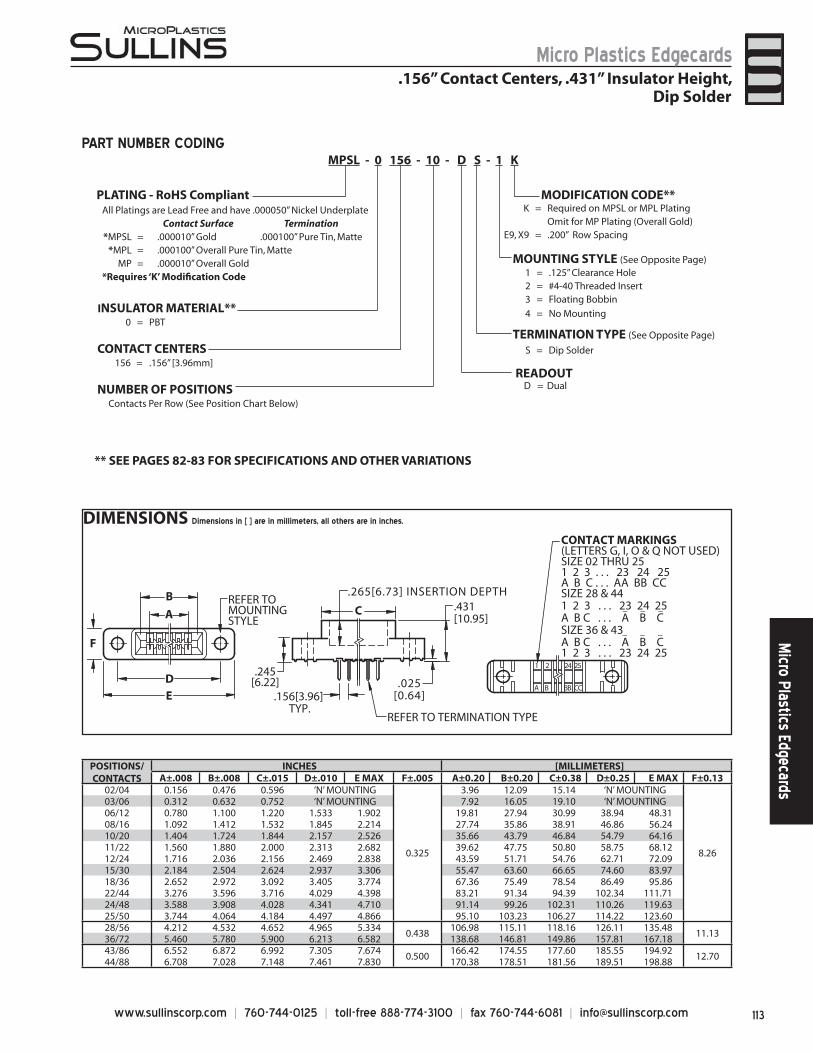
113www.sullinscorp.com | 760-744-0125 | toll-free 888-774-3100 | fax 760-744-6081 | [email protected]
Micro Plastics EdgecardsM
icro Plastics Edgecards
DIMENSIONS Dimensions in [ ] are in millimeters, all others are in inches.
A
D
B
E
F
1 2 24 25
A B BB CC
CREFER TOMOUNTINGSTYLE
.156[3.96] TYP.
.265[6.73] INSERTION DEPTH .431[10.95]
.245[6.22] .025
[0.64]
REFER TO TERMINATION TYPE
CONTACT MARKINGS(LETTERS G, I, O & Q NOT USED)SIZE 02 THRU 251 2 3 . . . 23 24 25A B C . . . AA BB CCSIZE 28 & 441 2 3 . . . 23 24 25A B C . . . A B C SIZE 36 & 43A B C . . . A B C1 2 3 . . . 23 24 25
_ _ _
_ _ _
S = Dip Solder
MODIFICATION CODE**
TERMINATION TYPE (See Opposite Page)
CONTACT CENTERS156 = .156” [3.96mm]
NUMBER OF POSITIONSContacts Per Row (See Position Chart Below)
INSULATOR MATERIAL**0 = PBT
** SEE PAGES 82-83 FOR SPECIFICATIONS AND OTHER VARIATIONS
1 = .125” Clearance Hole2 = #4-40 Threaded Insert3 = Floating Bobbin
4 = No Mounting
MOUNTING STYLE (See Opposite Page)
All Platings are Lead Free and have .000050” Nickel UnderplateContact Surface Termination
*MPSL = .000010” Gold .000100” Pure Tin, Matte*MPL = .000100” Overall Pure Tin, Matte
MP = .000010” Overall Gold *Requires ‘K’ Modifi cation Code
K = Required on MPSL or MPL PlatingOmit for MP Plating (Overall Gold)
E9, X9 = .200” Row Spacing
READOUT
MPSL - 0 156 - 10 - D S - 1 KPART NUMBER CODING
POSITIONS/CONTACTS
INCHES [MILLIMETERS]A±.008 B±.008 C±.015 D±.010 E MAX F±.005 A±0.20 B±0.20 C±0.38 D±0.25 E MAX F±0.13
02/04 0.156 0.476 0.596 ‘N’ MOUNTING
0.325
3.96 12.09 15.14 ‘N’ MOUNTING
8.26
03/06 0.312 0.632 0.752 ‘N’ MOUNTING 7.92 16.05 19.10 ‘N’ MOUNTING06/12 0.780 1.100 1.220 1.533 1.902 19.81 27.94 30.99 38.94 48.3108/16 1.092 1.412 1.532 1.845 2.214 27.74 35.86 38.91 46.86 56.2410/20 1.404 1.724 1.844 2.157 2.526 35.66 43.79 46.84 54.79 64.1611/22 1.560 1.880 2.000 2.313 2.682 39.62 47.75 50.80 58.75 68.1212/24 1.716 2.036 2.156 2.469 2.838 43.59 51.71 54.76 62.71 72.0915/30 2.184 2.504 2.624 2.937 3.306 55.47 63.60 66.65 74.60 83.9718/36 2.652 2.972 3.092 3.405 3.774 67.36 75.49 78.54 86.49 95.8622/44 3.276 3.596 3.716 4.029 4.398 83.21 91.34 94.39 102.34 111.7124/48 3.588 3.908 4.028 4.341 4.710 91.14 99.26 102.31 110.26 119.6325/50 3.744 4.064 4.184 4.497 4.866 95.10 103.23 106.27 114.22 123.6028/56 4.212 4.532 4.652 4.965 5.334
0.438106.98 115.11 118.16 126.11 135.48
11.1336/72 5.460 5.780 5.900 6.213 6.582 138.68 146.81 149.86 157.81 167.1843/86 6.552 6.872 6.992 7.305 7.674
0.500166.42 174.55 177.60 185.55 194.92
12.7044/88 6.708 7.028 7.148 7.461 7.830 170.38 178.51 181.56 189.51 198.88
.156” Contact Centers, .431” Insulator Height,Dip Solder
D = Dual
PLATING - RoHS Compliant
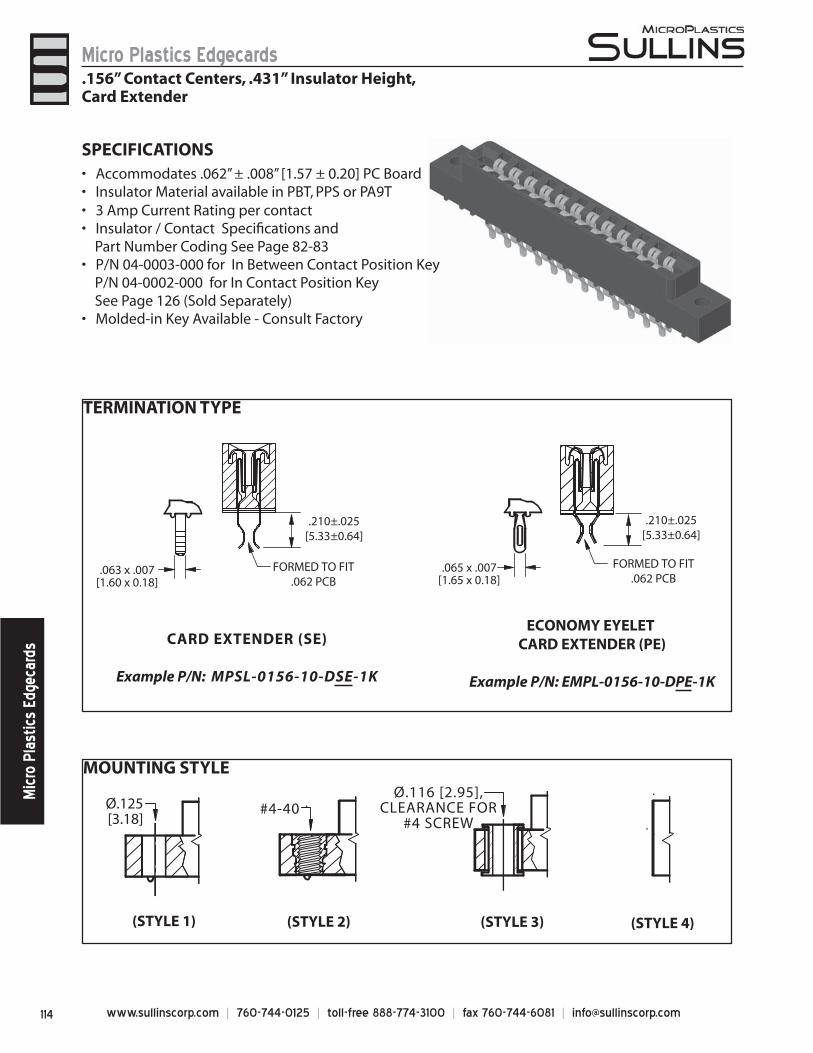
www.sullinscorp.com | 760-744-0125 | toll-free 888-774-3100 | fax 760-744-6081 | [email protected]
Micro Plastics EdgecardsM
icro
Pla
stic
s Ed
geca
rds
MOUNTING STYLE
TERMINATION TYPE
Ø.125[3.18]
#4-40
(STYLE 1) (STYLE 2) (STYLE 3) (STYLE 4)
Ø.116 [2.95],CLEARANCE FOR
#4 SCREW
.210±.025[5.33±0.64]
FORMED TO FIT.062 PCB
CARD EXTENDER (SE)
Example P/N: MPSL-0156-10-DSE-1K
ECONOMY EYELET CARD EXTENDER (PE)
Example P/N: EMPL-0156-10-DPE-1K
.210±.025[5.33±0.64]
FORMED TO FIT.062 PCB
.063 x .007[1.60 x 0.18]
.065 x .007[1.65 x 0.18]
SPECIFICATIONS
Acc• ommodates .062” ± .008” [1.57 ± 0.20] PC BoardInsulator Material available in PBT, PPS or PA9T• 3 Amp Current Rating • per contactInsulator / Contact Specifi cations and •
Part Number Coding See Page 82-83P/N 04-0003-000 for In Between Contact Position Key •
P/N 04-0002-000 for In Contact Position Key See Page 126 (Sold Separately)
Molded-in Key Available - Consult Factory•
.156” Contact Centers, .431” Insulator Height,Card Extender
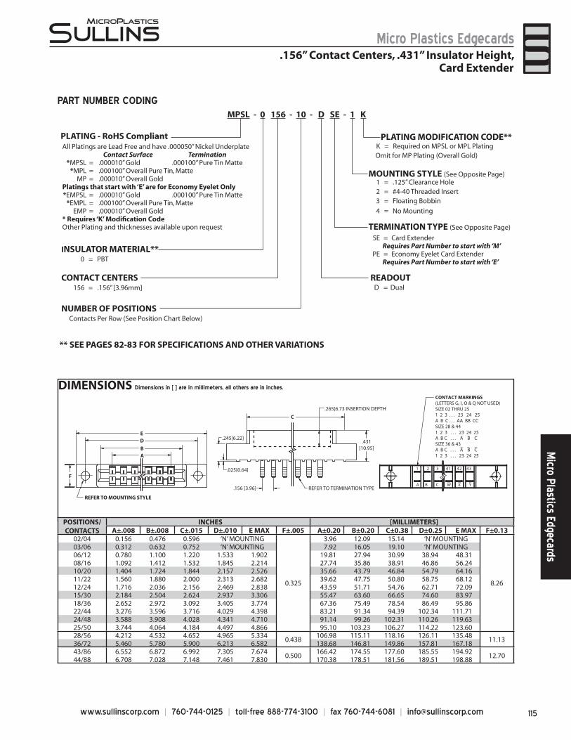
115www.sullinscorp.com | 760-744-0125 | toll-free 888-774-3100 | fax 760-744-6081 | [email protected]
Micro Plastics EdgecardsM
icro Plastics Edgecards
DIMENSIONS Dimensions in [ ] are in millimeters, all others are in inches.
C
.431[10.95]
.245[6.22]
.025[0.64]
CONTACT MARKINGS(LETTERS G, I, O & Q NOT USED)SIZE 02 THRU 251 2 3 . . . 23 24 25A B C . . . AA BB CCSIZE 28 & 441 2 3 . . . 23 24 25A B C . . . A B C SIZE 36 & 43A B C . . . A B C1 2 3 . . . 23 24 25
B
DE
A
REFER TO MOUNTING STYLE
REFER TO TERMINATION TYPE.156 [3.96]A B C W X Y
1 2 3 41 42 43
F
_ _ _
_ _ _
.265[6.73 INSERTION DEPTH
_ _ _
MPSL - 0 156 - 10 - D SE - 1 K
CONTACT CENTERS156 = .156” [3.96mm]
NUMBER OF POSITIONSContacts Per Row (See Position Chart Below)
1 = .125” Clearance Hole2 = #4-40 Threaded Insert3 = Floating Bobbin
4 = No Mounting
INSULATOR MATERIAL**0 = PBT
K = Required on MPSL or MPL PlatingOmit for MP Plating (Overall Gold)
PLATING MODIFICATION CODE**
MOUNTING STYLE (See Opposite Page)
TERMINATION TYPE (See Opposite Page)
READOUT
** SEE PAGES 82-83 FOR SPECIFICATIONS AND OTHER VARIATIONS
SE = Card ExtenderRequires Part Number to start with ‘M’
PE = Economy Eyelet Card ExtenderRequires Part Number to start with ‘E’
All Platings are Lead Free and have .000050” Nickel UnderplateContact Surface Termination
*MPSL = .000010” Gold .000100” Pure Tin Matte*MPL = .000100” Overall Pure Tin, Matte
MP = .000010” Overall GoldPlatings that start with ‘E’ are for Economy Eyelet Only*EMPSL = .000010” Gold .000100” Pure Tin Matte
*EMPL = .000100” Overall Pure Tin, MatteEMP = .000010” Overall Gold
* Requires ‘K’ Modifi cation CodeOther Plating and thicknesses available upon request
PART NUMBER CODING
.156” Contact Centers, .431” Insulator Height,Card Extender
POSITIONS/CONTACTS
INCHES [MILLIMETERS]A±.008 B±.008 C±.015 D±.010 E MAX F±.005 A±0.20 B±0.20 C±0.38 D±0.25 E MAX F±0.13
02/04 0.156 0.476 0.596 ‘N’ MOUNTING
0.325
3.96 12.09 15.14 ‘N’ MOUNTING
8.26
03/06 0.312 0.632 0.752 ‘N’ MOUNTING 7.92 16.05 19.10 ‘N’ MOUNTING06/12 0.780 1.100 1.220 1.533 1.902 19.81 27.94 30.99 38.94 48.3108/16 1.092 1.412 1.532 1.845 2.214 27.74 35.86 38.91 46.86 56.2410/20 1.404 1.724 1.844 2.157 2.526 35.66 43.79 46.84 54.79 64.1611/22 1.560 1.880 2.000 2.313 2.682 39.62 47.75 50.80 58.75 68.1212/24 1.716 2.036 2.156 2.469 2.838 43.59 51.71 54.76 62.71 72.0915/30 2.184 2.504 2.624 2.937 3.306 55.47 63.60 66.65 74.60 83.9718/36 2.652 2.972 3.092 3.405 3.774 67.36 75.49 78.54 86.49 95.8622/44 3.276 3.596 3.716 4.029 4.398 83.21 91.34 94.39 102.34 111.7124/48 3.588 3.908 4.028 4.341 4.710 91.14 99.26 102.31 110.26 119.6325/50 3.744 4.064 4.184 4.497 4.866 95.10 103.23 106.27 114.22 123.6028/56 4.212 4.532 4.652 4.965 5.334
0.438106.98 115.11 118.16 126.11 135.48
11.1336/72 5.460 5.780 5.900 6.213 6.582 138.68 146.81 149.86 157.81 167.1843/86 6.552 6.872 6.992 7.305 7.674
0.500166.42 174.55 177.60 185.55 194.92
12.7044/88 6.708 7.028 7.148 7.461 7.830 170.38 178.51 181.56 189.51 198.88
D = Dual
PLATING - RoHS Compliant
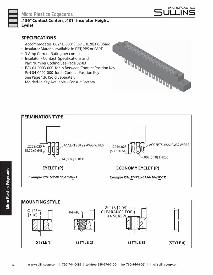
www.sullinscorp.com | 760-744-0125 | toll-free 888-774-3100 | fax 760-744-6081 | [email protected]
Micro Plastics EdgecardsM
icro
Pla
stic
s Ed
geca
rds
MOUNTING STYLE
TERMINATION TYPE
Ø.125[3.18]
#4-40
(STYLE 1) (STYLE 2) (STYLE 3) (STYLE 4)
Ø.116 [2.95],CLEARANCE FOR
#4 SCREW
.225±.025[5.72±0.64]
ACCEPTS 3#22 AWG WIRES
.007[0.18] THICK
ECONOMY EYELET (P)
Example P/N: EMPSL-0156-10-DP-1K
EYELET (P)
Example P/N: MP-0156-10-DP-1
.225±.025[5.72±0.64]
ACCEPTS 3#22 AWG WIRES
.014 [0.36] THICK
.156” Contact Centers, .431” Insulator Height,Eyelet
SPECIFICATIONSAcc• ommodates .062” ± .008” [1.57 ± 0.20] PC BoardInsulator Material available in PBT, PPS or PA9T• 3 Amp Current Rating • per contactInsulator / Contact Specifi cations and •
Part Number Coding See Page 82-83P/N 04-0003-000 for In Between Contact Position Key •
P/N 04-0002-000 for In Contact Position Key See Page 126 (Sold Separately)
Molded-in Key Available - Consult Factory•
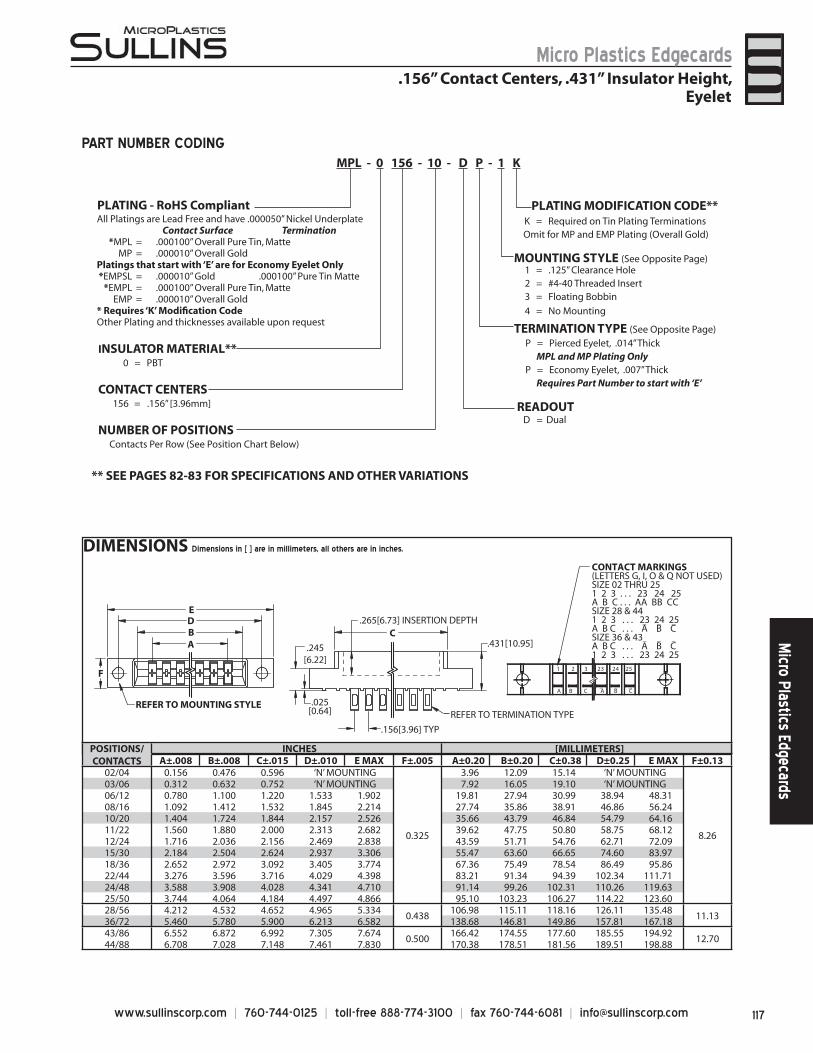
117www.sullinscorp.com | 760-744-0125 | toll-free 888-774-3100 | fax 760-744-6081 | [email protected]
Micro Plastics EdgecardsM
icro Plastics Edgecards
DIMENSIONS Dimensions in [ ] are in millimeters, all others are in inches.
POSITIONS/CONTACTS
INCHES [MILLIMETERS]A±.008 B±.008 C±.015 D±.010 E MAX F±.005 A±0.20 B±0.20 C±0.38 D±0.25 E MAX F±0.13
02/04 0.156 0.476 0.596 ‘N’ MOUNTING
0.325
3.96 12.09 15.14 ‘N’ MOUNTING
8.26
03/06 0.312 0.632 0.752 ‘N’ MOUNTING 7.92 16.05 19.10 ‘N’ MOUNTING06/12 0.780 1.100 1.220 1.533 1.902 19.81 27.94 30.99 38.94 48.3108/16 1.092 1.412 1.532 1.845 2.214 27.74 35.86 38.91 46.86 56.2410/20 1.404 1.724 1.844 2.157 2.526 35.66 43.79 46.84 54.79 64.1611/22 1.560 1.880 2.000 2.313 2.682 39.62 47.75 50.80 58.75 68.1212/24 1.716 2.036 2.156 2.469 2.838 43.59 51.71 54.76 62.71 72.0915/30 2.184 2.504 2.624 2.937 3.306 55.47 63.60 66.65 74.60 83.9718/36 2.652 2.972 3.092 3.405 3.774 67.36 75.49 78.54 86.49 95.8622/44 3.276 3.596 3.716 4.029 4.398 83.21 91.34 94.39 102.34 111.7124/48 3.588 3.908 4.028 4.341 4.710 91.14 99.26 102.31 110.26 119.6325/50 3.744 4.064 4.184 4.497 4.866 95.10 103.23 106.27 114.22 123.6028/56 4.212 4.532 4.652 4.965 5.334
0.438106.98 115.11 118.16 126.11 135.48
11.1336/72 5.460 5.780 5.900 6.213 6.582 138.68 146.81 149.86 157.81 167.1843/86 6.552 6.872 6.992 7.305 7.674
0.500166.42 174.55 177.60 185.55 194.92
12.7044/88 6.708 7.028 7.148 7.461 7.830 170.38 178.51 181.56 189.51 198.88
.025[0.64]
.245[6.22]
F
ABDE
REFER TO MOUNTING STYLE
.431[10.95]C
.265[6.73] INSERTION DEPTH
.156[3.96] TYP
REFER TO TERMINATION TYPE
A B C A B C
1 2 3 23 24 25
_ _ _
CONTACT MARKINGS(LETTERS G, I, O & Q NOT USED)SIZE 02 THRU 251 2 3 . . . 23 24 25A B C . . . AA BB CCSIZE 28 & 441 2 3 . . . 23 24 25A B C . . . A B CSIZE 36 & 43A B C . . . A B C1 2 3 . . . 23 24 25
_ _ _
_ _ _
CONTACT CENTERS156 = .156” [3.96mm]
NUMBER OF POSITIONSContacts Per Row (See Position Chart Below)
1 = .125” Clearance Hole2 = #4-40 Threaded Insert3 = Floating Bobbin
4 = No Mounting
INSULATOR MATERIAL**0 = PBT
PLATING MODIFICATION CODE**
MOUNTING STYLE (See Opposite Page)
TERMINATION TYPE (See Opposite Page)
READOUT
** SEE PAGES 82-83 FOR SPECIFICATIONS AND OTHER VARIATIONS
P = Pierced Eyelet, .014” ThickMPL and MP Plating Only
P = Economy Eyelet, .007” ThickRequires Part Number to start with ‘E’
K = Required on Tin Plating TerminationsOmit for MP and EMP Plating (Overall Gold)
All Platings are Lead Free and have .000050” Nickel UnderplateContact Surface Termination
*MPL = .000100” Overall Pure Tin, MatteMP = .000010” Overall Gold
Platings that start with ‘E’ are for Economy Eyelet Only*EMPSL = .000010” Gold .000100” Pure Tin Matte
*EMPL = .000100” Overall Pure Tin, MatteEMP = .000010” Overall Gold
* Requires ‘K’ Modifi cation CodeOther Plating and thicknesses available upon request
MPL - 0 156 - 10 - D P - 1 K
PART NUMBER CODING
.156” Contact Centers, .431” Insulator Height,Eyelet
D = Dual
PLATING - RoHS Compliant
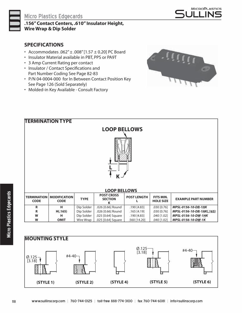
www.sullinscorp.com | 760-744-0125 | toll-free 888-774-3100 | fax 760-744-6081 | [email protected]
Micro Plastics EdgecardsM
icro
Pla
stic
s Ed
geca
rds
MOUNTING STYLE
Ø.125 [3.18]
(STYLE 1) (STYLE 2)
#4-40
(STYLE 6)
#4-40
(STYLE 4) (STYLE 5)
Ø.125[3.18]
SPECIFICATIONSAccommo• dates .062” ± .008” [1.57 ± 0.20] PC BoardInsulator Material available in PBT, PPS or PA9T• 3 Amp Current Rating • per contactInsulator / Contact Specifi cations and •
Part Number Coding See Page 82-83P/N 04-0004-000 for In Between Contact Position Key •
See Page 126 (Sold Separately)Molded-in Key Available - Consult Factory•
.156” Contact Centers, .610” Insulator Height,Wire Wrap & Dip Solder
LOOP BELLOWSTERMINATION
CODEMODIFICATION
CODE TYPE
POST CROSS SECTION
K
POST LENGTH L
FITS MIN.HOLE SIZE
EXAMPLE PART NUMBER
R H Dip Solder .026 [0.66] Round .190 [4.83] .030 [0.76] MPSL-0156-10-DR-1HKR H(.165) Dip Solder .026 [0.66] Round .165 [4.19] .030 [0.76] MPSL-0156-10-DR-1HK(.165)W H Dip Solder .025 [0.64] Square .190 [4.83] .040 [1.02] MPSL-0156-10-DW-1HKW OMIT Wire Wrap .025 [0.64] Square .560 [14.20] .040 [1.02] MPSL-0156-10-DW-1K
LOOP BELLOWS
K
L
TERMINATION TYPE
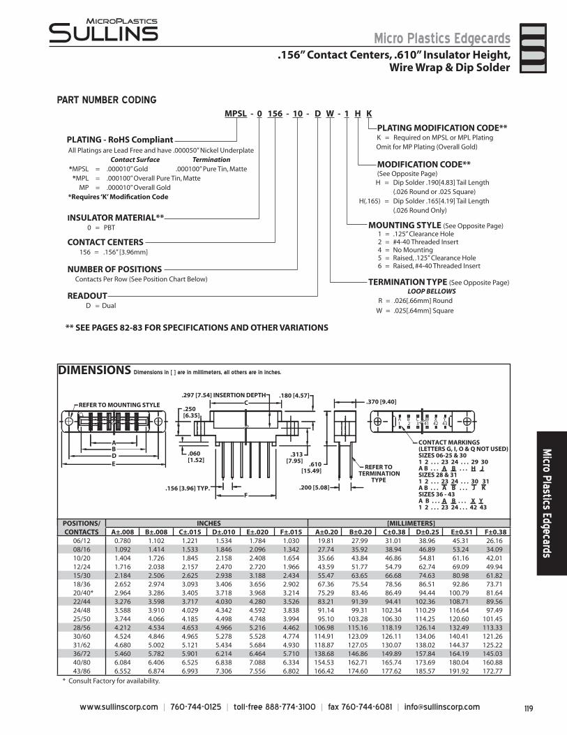
119www.sullinscorp.com | 760-744-0125 | toll-free 888-774-3100 | fax 760-744-6081 | [email protected]
Micro Plastics EdgecardsM
icro Plastics Edgecards
DIMENSIONS Dimensions in [ ] are in millimeters, all others are in inches.
PLATING MODIFICATION CODE**K = Required on MPSL or MPL PlatingOmit for MP Plating (Overall Gold)
H = Dip Solder .190[4.83] Tail Length(.026 Round or .025 Square)
H(.165) = Dip Solder .165[4.19] Tail Length(.026 Round Only)
TERMINATION TYPE (See Opposite Page)
MOUNTING STYLE (See Opposite Page)
LOOP BELLOWSR = .026[.66mm] Round
W = .025[.64mm] Square
1 = .125” Clearance Hole2 = #4-40 Threaded Insert4 = No Mounting5 = Raised, .125” Clearance Hole6 = Raised, #4-40 Threaded Insert
All Platings are Lead Free and have .000050” Nickel UnderplateContact Surface Termination
*MPSL = .000010” Gold .000100” Pure Tin, Matte*MPL = .000100” Overall Pure Tin, Matte
MP = .000010” Overall Gold *Requires ‘K’ Modifi cation Code
MODIFICATION CODE**(See Opposite Page)
CONTACT CENTERS156 = .156” [3.96mm]
NUMBER OF POSITIONSContacts Per Row (See Position Chart Below)
INSULATOR MATERIAL**0 = PBT
READOUT
** SEE PAGES 82-83 FOR SPECIFICATIONS AND OTHER VARIATIONS
CONTACT MARKINGS(LETTERS G, I, O & Q NOT USED)SIZES 06-25 & 301 2 . . . 23 24 . . . 29 30A B . . . A B . . . H JSIZES 28 & 311 2 . . . 23 24 . . . 30 31A B . . . A B . . . J KSIZES 36 - 43A B . . . A B . . . X Y1 2 . . . 23 24 . . . 42 43
A B C W X Y1 2 3 41 42 43
.370 [9.40]
AB
C
DE
F.156 [3.96] TYP.
.060[1.52]
.250[6.35]
.180 [4.57]
.313[7.95]
.297 [7.54] INSERTION DEPTH
REFER TO MOUNTING STYLE
.200 [5.08]
REFER TO TERMINATION
TYPE
.610[15.49]
_ _ _
MPSL - 0 156 - 10 - D W - 1 H K
PART NUMBER CODING
.156” Contact Centers, .610” Insulator Height,Wire Wrap & Dip Solder
POSITIONS/CONTACTS
INCHES [MILLIMETERS]A±.008 B±.008 C±.015 D±.010 E±.020 F±.015 A±0.20 B±0.20 C±0.38 D±0.25 E±0.51 F±0.38
06/12 0.780 1.102 1.221 1.534 1.784 1.030 19.81 27.99 31.01 38.96 45.31 26.1608/16 1.092 1.414 1.533 1.846 2.096 1.342 27.74 35.92 38.94 46.89 53.24 34.0910/20 1.404 1.726 1.845 2.158 2.408 1.654 35.66 43.84 46.86 54.81 61.16 42.0112/24 1.716 2.038 2.157 2.470 2.720 1.966 43.59 51.77 54.79 62.74 69.09 49.9415/30 2.184 2.506 2.625 2.938 3.188 2.434 55.47 63.65 66.68 74.63 80.98 61.8218/36 2.652 2.974 3.093 3.406 3.656 2.902 67.36 75.54 78.56 86.51 92.86 73.7120/40* 2.964 3.286 3.405 3.718 3.968 3.214 75.29 83.46 86.49 94.44 100.79 81.6422/44 3.276 3.598 3.717 4.030 4.280 3.526 83.21 91.39 94.41 102.36 108.71 89.5624/48 3.588 3.910 4.029 4.342 4.592 3.838 91.14 99.31 102.34 110.29 116.64 97.4925/50 3.744 4.066 4.185 4.498 4.748 3.994 95.10 103.28 106.30 114.25 120.60 101.4528/56 4.212 4.534 4.653 4.966 5.216 4.462 106.98 115.16 118.19 126.14 132.49 113.3330/60 4.524 4.846 4.965 5.278 5.528 4.774 114.91 123.09 126.11 134.06 140.41 121.2631/62 4.680 5.002 5.121 5.434 5.684 4.930 118.87 127.05 130.07 138.02 144.37 125.2236/72 5.460 5.782 5.901 6.214 6.464 5.710 138.68 146.86 149.89 157.84 164.19 145.0340/80 6.084 6.406 6.525 6.838 7.088 6.334 154.53 162.71 165.74 173.69 180.04 160.8843/86 6.552 6.874 6.993 7.306 7.556 6.802 166.42 174.60 177.62 185.57 191.92 172.77
D = Dual
PLATING - RoHS Compliant
* Consult Factory for availability.
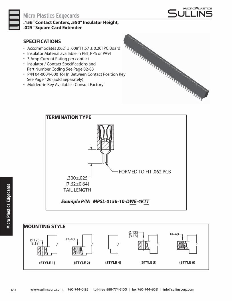
www.sullinscorp.com | 760-744-0125 | toll-free 888-774-3100 | fax 760-744-6081 | [email protected]
Micro Plastics EdgecardsM
icro
Pla
stic
s Ed
geca
rds
MOUNTING STYLE
TERMINATION TYPE
FORMED TO FIT .062 PCB.300±.025
[7.62±0.64]TAIL LENGTH
Example P/N: MPSL-0156-10-DWE-4KTT
SPECIFICATIONSAccommo• dates .062” ± .008” [1.57 ± 0.20] PC BoardInsulator Material available in PBT, PPS or PA9T• 3 Amp Current Rating • per contactInsulator / Contact Specifi cations and •
Part Number Coding See Page 82-83P/N 04-0004-000 for In Between Contact Position Key •
See Page 126 (Sold Separately)Molded-in Key Available - Consult Factory•
.156” Contact Centers, .550” Insulator Height,
.025” Square Card Extender
Ø.125 [3.18]
(STYLE 1) (STYLE 2)
#4-40
(STYLE 6)
#4-40
(STYLE 4) (STYLE 5)
Ø.125[3.18]
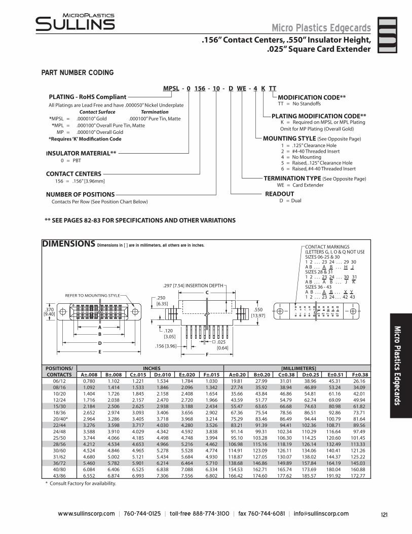
121www.sullinscorp.com | 760-744-0125 | toll-free 888-774-3100 | fax 760-744-6081 | [email protected]
Micro Plastics EdgecardsM
icro Plastics Edgecards
DIMENSIONS Dimensions in [ ] are in millimeters, all others are in inches.
.250[6.35]
.550[13.97]
.025[0.64]
F
C
.120[3.05]
E
D
B
.156 [3.96]
A
.370[9.40]
REFER TO MOUNTING STYLE
.297 [7.54] INSERTION DEPTH
A B C D E U V W X Y
1 2 3 4 5 39 40 41 42 43
CONTACT MARKINGS(LETTERS G, I, O & Q NOT USESIZES 06-25 & 301 2 . . . 23 24 . . . 29 30A B . . . A B . . . H JSIZES 28 & 311 2 . . . 23 24 . . . 30 31A B . . . A B . . . J KSIZES 36 - 43A B . . . A B . . . X Y1 2 . . . 23 24 . . . 42 43
1 = .125” Clearance Hole2 = #4-40 Threaded Insert4 = No Mounting5 = Raised, .125” Clearance Hole6 = Raised, #4-40 Threaded Insert
All Platings are Lead Free and have .000050” Nickel UnderplateContact Surface Termination
*MPSL = .000010” Gold .000100” Pure Tin, Matte*MPL = .000100” Overall Pure Tin, Matte
MP = .000010” Overall Gold *Requires ‘K’ Modifi cation Code MOUNTING STYLE (See Opposite Page)
TERMINATION TYPE (See Opposite Page)
TT = No Standoffs
WE = Card Extender
CONTACT CENTERS156 = .156” [3.96mm]
NUMBER OF POSITIONSContacts Per Row (See Position Chart Below)
INSULATOR MATERIAL**0 = PBT
READOUT
** SEE PAGES 82-83 FOR SPECIFICATIONS AND OTHER VARIATIONS
K = Required on MPSL or MPL PlatingOmit for MP Plating (Overall Gold)
PLATING MODIFICATION CODE**
MODIFICATION CODE**
MPSL - 0 156 - 10 - D WE - 4 K TT
PART NUMBER CODING
.156” Contact Centers, .550” Insulator Height,.025” Square Card Extender
POSITIONS/CONTACTS
INCHES [MILLIMETERS]A±.008 B±.008 C±.015 D±.010 E±.020 F±.015 A±0.20 B±0.20 C±0.38 D±0.25 E±0.51 F±0.38
06/12 0.780 1.102 1.221 1.534 1.784 1.030 19.81 27.99 31.01 38.96 45.31 26.1608/16 1.092 1.414 1.533 1.846 2.096 1.342 27.74 35.92 38.94 46.89 53.24 34.0910/20 1.404 1.726 1.845 2.158 2.408 1.654 35.66 43.84 46.86 54.81 61.16 42.0112/24 1.716 2.038 2.157 2.470 2.720 1.966 43.59 51.77 54.79 62.74 69.09 49.9415/30 2.184 2.506 2.625 2.938 3.188 2.434 55.47 63.65 66.68 74.63 80.98 61.8218/36 2.652 2.974 3.093 3.406 3.656 2.902 67.36 75.54 78.56 86.51 92.86 73.7120/40* 2.964 3.286 3.405 3.718 3.968 3.214 75.29 83.46 86.49 94.44 100.79 81.6422/44 3.276 3.598 3.717 4.030 4.280 3.526 83.21 91.39 94.41 102.36 108.71 89.5624/48 3.588 3.910 4.029 4.342 4.592 3.838 91.14 99.31 102.34 110.29 116.64 97.4925/50 3.744 4.066 4.185 4.498 4.748 3.994 95.10 103.28 106.30 114.25 120.60 101.4528/56 4.212 4.534 4.653 4.966 5.216 4.462 106.98 115.16 118.19 126.14 132.49 113.3330/60 4.524 4.846 4.965 5.278 5.528 4.774 114.91 123.09 126.11 134.06 140.41 121.2631/62 4.680 5.002 5.121 5.434 5.684 4.930 118.87 127.05 130.07 138.02 144.37 125.2236/72 5.460 5.782 5.901 6.214 6.464 5.710 138.68 146.86 149.89 157.84 164.19 145.0340/80 6.084 6.406 6.525 6.838 7.088 6.334 154.53 162.71 165.74 173.69 180.04 160.8843/86 6.552 6.874 6.993 7.306 7.556 6.802 166.42 174.60 177.62 185.57 191.92 172.77
D = Dual
PLATING - RoHS Compliant
* Consult Factory for availability.
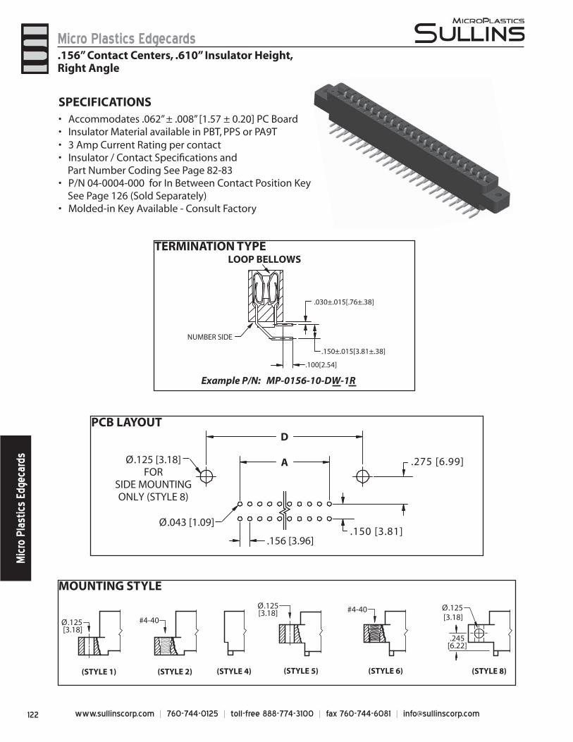
www.sullinscorp.com | 760-744-0125 | toll-free 888-774-3100 | fax 760-744-6081 | [email protected]
Micro Plastics EdgecardsM
icro
Pla
stic
s Ed
geca
rds
MOUNTING STYLE
TERMINATION TYPE
PCB LAYOUT
.030±.015[.76±.38]
.150±.015[3.81±.38]
NUMBER SIDE
LOOP BELLOWS
.100[2.54]
Example P/N: MP-0156-10-DW-1R
.156 [3.96]
A
D
Ø.125 [3.18]FOR
SIDE MOUNTINGONLY (STYLE 8)
Ø.043 [1.09].150 [3.81]
.275 [6.99]
SPECIFICATIONSAccommo• dates .062” ± .008” [1.57 ± 0.20] PC BoardInsulator Material available in PBT, PPS or PA9T• 3 Amp Current Rating • per contactInsulator / Contact Specifi cations and •
Part Number Coding See Page 82-83P/N 04-0004-000 for In Between Contact Position Key•
See Page 126 (Sold Separately)Molded-in Key Available - Consult Factory•
.156” Contact Centers, .610” Insulator Height,Right Angle
(STYLE 8)
.245[6.22]
Ø.125[3.18]
Ø.125 [3.18]
(STYLE 1) (STYLE 2)
#4-40
(STYLE 6)
#4-40
(STYLE 4) (STYLE 5)
Ø.125[3.18]
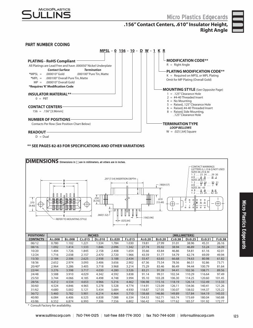
123www.sullinscorp.com | 760-744-0125 | toll-free 888-774-3100 | fax 760-744-6081 | [email protected]
Micro Plastics EdgecardsM
icro Plastics Edgecards
DIMENSIONS Dimensions in [ ] are in millimeters, all others are in inches.
1 = .125” Clearance Hole2 = #4-40 Threaded Insert4 = No Mounting5 = Raised, .125” Clearance Hole6 = Raised, #4-40 Threaded Insert8 = Raised, Side Mounting,
.125” Clearance Hole
LOOP BELLOWSW = .025 [.64] Square
All Platings are Lead Free and have .000050” Nickel UnderplateContact Surface Termination
*MPSL = .000010” Gold .000100” Pure Tin, Matte*MPL = .000100” Overall Pure Tin, Matte
MP = .000010” Overall Gold *Requires ‘K’ Modifi cation Code
MOUNTING STYLE (See Opposite Page)
TERMINATION TYPE
R = Right Angle
MPSL - 0 156 - 10 - D W - 1 K R
CONTACT CENTERS156 = .156” [3.96mm]
NUMBER OF POSITIONSContacts Per Row (See Position Chart Below)
INSULATOR MATERIAL**0 = PBT
READOUT
** SEE PAGES 82-83 FOR SPECIFICATIONS AND OTHER VARIATIONS
K = Required on MPSL or MPL PlatingOmit for MP Plating (Overall Gold)
MODIFICATION CODE**
PLATING MODIFICATION CODE**
C
.610[15.49]
.180[4.57]
.250[6.35]
.060[1.52]
F
.025[.64]
B
E
D
A
.156[3.96]REFER TO MOUNTING STYLE
A B C W X Y
1 2 3 141 142 143
.370[9.40]
CONTACT MARKINGS(LETTERS G, I, O & Q NOT USED)SIZES 06-25 & 301 2 . . . 23 24 . . . 29 30A B . . . A B . . . H JSIZES 28 & 311 2 . . . 23 24 . . . 30 31A B . . . A B . . . J KSIZES 36 - 43A B . . . A B . . . X Y1 2 . . . 23 24 . . . 42 43
.297 [7.54] INSERTION DEPTH
PART NUMBER CODING
.156” Contact Centers, .610” Insulator Height,Right Angle
D = Dual
POSITIONS/CONTACTS
INCHES [MILLIMETERS]A±.008 B±.008 C±.015 D±.010 E±.020 F±.015 A±0.20 B±0.20 C±0.38 D±0.25 E±0.51 F±0.38
06/12 0.780 1.102 1.221 1.534 1.784 1.030 19.81 27.99 31.01 38.96 45.31 26.1608/16 1.092 1.414 1.533 1.846 2.096 1.342 27.74 35.92 38.94 46.89 53.24 34.0910/20 1.404 1.726 1.845 2.158 2.408 1.654 35.66 43.84 46.86 54.81 61.16 42.0112/24 1.716 2.038 2.157 2.470 2.720 1.966 43.59 51.77 54.79 62.74 69.09 49.9415/30 2.184 2.506 2.625 2.938 3.188 2.434 55.47 63.65 66.68 74.63 80.98 61.8218/36 2.652 2.974 3.093 3.406 3.656 2.902 67.36 75.54 78.56 86.51 92.86 73.7120/40* 2.964 3.286 3.405 3.718 3.968 3.214 75.29 83.46 86.49 94.44 100.79 81.6422/44 3.276 3.598 3.717 4.030 4.280 3.526 83.21 91.39 94.41 102.36 108.71 89.5624/48 3.588 3.910 4.029 4.342 4.592 3.838 91.14 99.31 102.34 110.29 116.64 97.4925/50 3.744 4.066 4.185 4.498 4.748 3.994 95.10 103.28 106.30 114.25 120.60 101.4528/56 4.212 4.534 4.653 4.966 5.216 4.462 106.98 115.16 118.19 126.14 132.49 113.3330/60 4.524 4.846 4.965 5.278 5.528 4.774 114.91 123.09 126.11 134.06 140.41 121.2631/62 4.680 5.002 5.121 5.434 5.684 4.930 118.87 127.05 130.07 138.02 144.37 125.2236/72 5.460 5.782 5.901 6.214 6.464 5.710 138.68 146.86 149.89 157.84 164.19 145.0340/80 6.084 6.406 6.525 6.838 7.088 6.334 154.53 162.71 165.74 173.69 180.04 160.8843/86 6.552 6.874 6.993 7.306 7.556 6.802 166.42 174.60 177.62 185.57 191.92 172.77
PLATING - RoHS Compliant
* Consult Factory for availability.
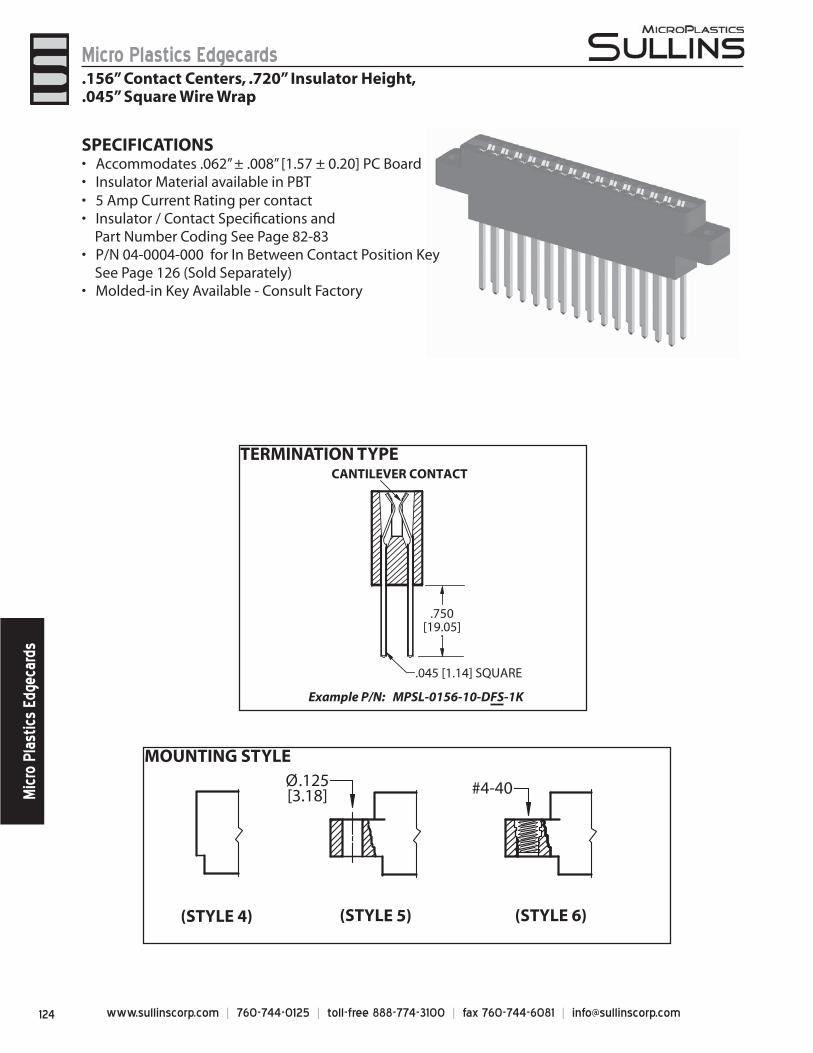
www.sullinscorp.com | 760-744-0125 | toll-free 888-774-3100 | fax 760-744-6081 | [email protected]
Micro Plastics EdgecardsM
icro
Pla
stic
s Ed
geca
rds
TERMINATION TYPE
MOUNTING STYLE
(STYLE 6)
#4-40
(STYLE 4) (STYLE 5)
Ø.125[3.18]
.750[19.05]
CANTILEVER CONTACT
.045 [1.14] SQUARE
Example P/N: MPSL-0156-10-DFS-1K
SPECIFICATIONSAccommodates .062” ± .008” [1.57 ± 0.20] PC Board• Insulator Material available in PBT• 5 Amp Current Rating • per contactInsulator / Contact Specifi cations and •
Part Number Coding See Page 82-83P/N 04-0004-000 for In Between Contact Position Key •
See Page 126 (Sold Separately)Molded-in Key Available - Consult Factory•
.156” Contact Centers, .720” Insulator Height,
.045” Square Wire Wrap
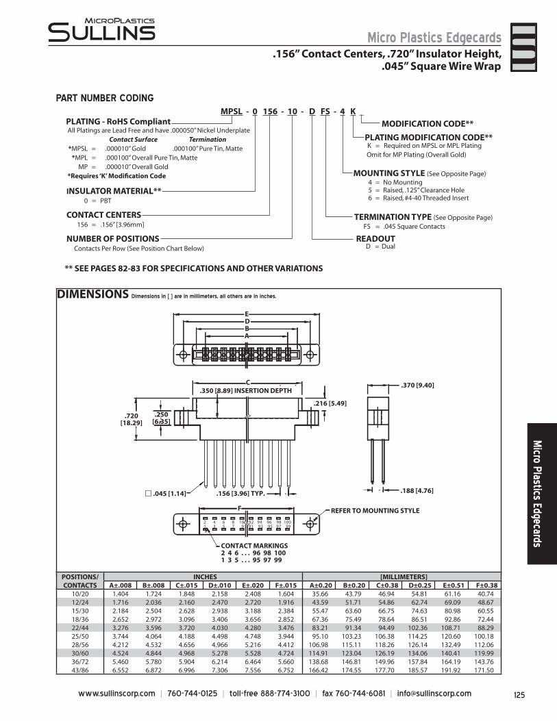
125www.sullinscorp.com | 760-744-0125 | toll-free 888-774-3100 | fax 760-744-6081 | [email protected]
Micro Plastics EdgecardsM
icro Plastics Edgecards
DIMENSIONS Dimensions in [ ] are in millimeters, all others are in inches.
.370 [9.40]
.188 [4.76]
A
.216 [5.49]
.250[6.35]
.720[18.29]
B
C
ED
.350 [8.89] INSERTION DEPTH
.156 [3.96] TYP.
2 4 6 8 10 92 94 96 98 100 1 3 5 7 9 91 93 95 97 99
CONTACT MARKINGS2 4 6 . . . 96 98 1001 3 5 . . . 95 97 99
REFER TO MOUNTING STYLE F
.045 [1.14]
PLATING MODIFICATION CODE**K = Required on MPSL or MPL PlatingOmit for MP Plating (Overall Gold)
** SEE PAGES 82-83 FOR SPECIFICATIONS AND OTHER VARIATIONS
FS = .045 Square ContactsTERMINATION TYPE (See Opposite Page)
MOUNTING STYLE (See Opposite Page)4 = No Mounting5 = Raised, .125” Clearance Hole6 = Raised, #4-40 Threaded Insert
All Platings are Lead Free and have .000050” Nickel UnderplateContact Surface Termination
*MPSL = .000010” Gold .000100” Pure Tin, Matte*MPL = .000100” Overall Pure Tin, Matte
MP = .000010” Overall Gold *Requires ‘K’ Modifi cation Code
CONTACT CENTERS156 = .156” [3.96mm]
NUMBER OF POSITIONSContacts Per Row (See Position Chart Below)
INSULATOR MATERIAL**0 = PBT
READOUT
MODIFICATION CODE**
MPSL - 0 156 - 10 - D FS - 4 K _
PART NUMBER CODING
.156” Contact Centers, .720” Insulator Height,.045” Square Wire Wrap
POSITIONS/CONTACTS
INCHES [MILLIMETERS]A±.008 B±.008 C±.015 D±.010 E±.020 F±.015 A±0.20 B±0.20 C±0.38 D±0.25 E±0.51 F±0.38
10/20 1.404 1.724 1.848 2.158 2.408 1.604 35.66 43.79 46.94 54.81 61.16 40.7412/24 1.716 2.036 2.160 2.470 2.720 1.916 43.59 51.71 54.86 62.74 69.09 48.6715/30 2.184 2.504 2.628 2.938 3.188 2.384 55.47 63.60 66.75 74.63 80.98 60.5518/36 2.652 2.972 3.096 3.406 3.656 2.852 67.36 75.49 78.64 86.51 92.86 72.4422/44 3.276 3.596 3.720 4.030 4.280 3.476 83.21 91.34 94.49 102.36 108.71 88.2925/50 3.744 4.064 4.188 4.498 4.748 3.944 95.10 103.23 106.38 114.25 120.60 100.1828/56 4.212 4.532 4.656 4.966 5.216 4.412 106.98 115.11 118.26 126.14 132.49 112.0630/60 4.524 4.844 4.968 5.278 5.528 4.724 114.91 123.04 126.19 134.06 140.41 119.9936/72 5.460 5.780 5.904 6.214 6.464 5.660 138.68 146.81 149.96 157.84 164.19 143.7643/86 6.552 6.872 6.996 7.306 7.556 6.752 166.42 174.55 177.70 185.57 191.92 171.50
D = Dual
PLATING - RoHS Compliant
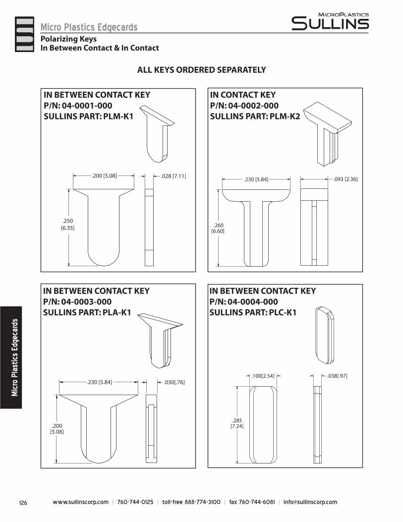
www.sullinscorp.com | 760-744-0125 | toll-free 888-774-3100 | fax 760-744-6081 | [email protected]
Micro Plastics EdgecardsM
icro
Pla
stic
s Ed
geca
rds
ALL KEYS ORDERED SEPARATELY
.230 [5.84]
.200[5.08]
.030[.76]
IN BETWEEN CONTACT KEYP/N: 04-0003-000SULLINS PART: PLA-K1
.100[2.54]
.285[7.24]
.038[.97]
IN BETWEEN CONTACT KEYP/N: 04-0004-000SULLINS PART: PLC-K1
.028 [7.11].200 [5.08]
.250[6.35]
IN BETWEEN CONTACT KEYP/N: 04-0001-000SULLINS PART: PLM-K1
Polarizing KeysIn Between Contact & In Contact
.093 [2.36].230 [5.84]
.260[6.60]
IN CONTACT KEYP/N: 04-0002-000SULLINS PART: PLM-K2
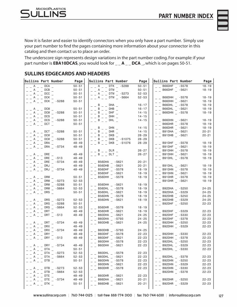
127www.sullinscorp.com | 760-744-0125 | toll-free 888-774-3100 | fax 760-744-6081 | [email protected]
Now it is faster and easier to identify connectors when you only have a part number. Simply use your part number to fi nd the pages containing more information about your connector in this catalog and then contact us to place an order.
The underscore sign represents design variations in the part number coding. For example: if your part number is EBA10DCAS, you would look for _ _ A _ _ DCA _, which is on pages 50-51.
SULLINS EDGECARDS AND HEADERSSullins Part Number Page Sullins Part Number Page Sullins Part Number Page_ _ A _ _ DCA _ 50-51 _ _ A _ _ DTK _ -S288 50-51 _ _ B66DHF _ -S578 18-19_ _ A _ _ DCB _ 50-51 _ _ A _ _ DTM _ 50-51 _ _ B66DHF _ -S621 18-19_ _ A _ _ DCC _ 50-51 _ _ A _ _ DTM _ -S273 52-53_ _ A _ _ DCK _ 50-51 _ _ A _ _ DTM _ -S664 52-53 _ _ B66DHH _ -S578 18-19_ _ A _ _ DCK _ -S288 50-51 _ _ B66DHH _ -S621 18-19
_ _ B _ _ DHA _ 16-17 _ _ B66DHL _ -S578 18-19_ _ A _ _ DCM _ 50-51 _ _ B _ _ DHB _ 16-17 _ _ B66DHL _ -S621 18-19_ _ A _ _ DCM _ -S288 50-51 _ _ B _ _ DHF _ 14-15 _ _ B66DHN _ -S578 18-19 _ _ A _ _ DCS _ 50-51 _ _ B _ _ DHH _ 14-15_ _ A _ _ DCS _ -S288 50-51 _ _ B _ _ DHL _ 14-15 _ _ B66DHN _ -S621 18-19_ _ A _ _ DCT _ 50-51 _ _ B66DHR _ -S578 18-19
_ _ B _ _ DHN _ 14-15 _ _ B66DHR _ -S621 18-19_ _ A _ _ DCT _ -S288 50-51 _ _ B _ _ DHR _ 14-15 _ _ B91DHA _ -S621 20-21_ _ A _ _ DCW _ 50-51 _ _ B _ _ DKB _ 28-29 _ _ B91DHB _ -S621 20-21_ _ A _ _ DCW _ -S288 50-51 _ _ B _ _ DKB _ -S1075 28-29_ _ A _ _ DRA _ 48-49 _ _ B _ _ DKB _ -S1076 28-29 _ _ B91DHF _ -S578 18-19_ _ A _ _ DRA _ -S734 48-49 _ _ B91DHF _ -S621 18-19
_ _ B _ _ DLR _ 26-27 _ _ B91DHH _ -S578 18-19_ _ A _ _ DRE _ 48-49 _ _ B _ _ DLT _ 26-27 _ _ B91DHH _ -S621 18-19_ _ A _ _ DRE _ -S13 48-49 _ _ B91DHL _ -S578 18-19_ _ A _ _ DRE _ -S734 48-49 _ _ B56DHA _ -S621 20-21_ _ A _ _ DRJ _ 48-49 _ _ B56DHB _ -S621 20-21 _ _ B91DHL _ -S621 18-19_ _ A _ _ DRJ _ -S734 48-49 _ _ B56DHF _ -S578 18-19 _ _ B91DHN _ -S578 18-19
_ _ B56DHF _ -S621 18-19 _ _ B91DHN _ -S621 18-19_ _ A _ _ DRM _ 50-51 _ _ B56DHH _ -S578 18-19 _ _ B91DHR _ -S578 18-19_ _ A _ _ DRM _ -S273 52-53 _ _ B91DHR _ -S621 18-19_ _ A _ _ DRM _ -S288 50-51 _ _ B56DHH _ -S621 18-19_ _ A _ _ DRM _ -S664 52-53 _ _ B56DHL _ -S578 18-19 _ _ B92DHA _ -S250 24-25_ _ A _ _ DRS _ 50-51 _ _ B56DHL _ -S621 18-19 _ _ B92DHA _ -S329 24-25
_ _ B56DHN _ -S578 18-19 _ _ B92DHB _ -S250 24-25_ _ A _ _ DRS _ -S273 52-53 _ _ B56DHN _ -S621 18-19 _ _ B92DHB _ -S329 24-25_ _ A _ _ DRS _ -S288 50-51 _ _ B92DHF _ -S250 22-23_ _ A _ _ DRS _ -S664 52-53 _ _ B56DHR _ -S578 18-19_ _ A _ _ DRT _ 48-49 _ _ B56DHR _ -S621 18-19 _ _ B92DHF _ -S329 22-23_ _ A _ _ DRT _ -S13 48-49 _ _ B60DHA _ -S621 24-25 _ _ B92DHF _ -S330 22-23
_ _ B60DHA _ -S793 24-25 _ _ B92DHF _ -S378 22-23_ _ A _ _ DRT _ -S734 48-49 _ _ B60DHB _ -S621 24-25 _ _ B92DHH _ -S250 22-23_ _ A _ _ DRX _ 48-49 _ _ B92DHH _ -S329 22-23_ _ A _ _ DRX _ -S734 48-49 _ _ B60DHB _ -S793 24-25_ _ A _ _ DRY _ 48-49 _ _ B60DHF _ -S578 22-23 _ _ B92DHH _ -S330 22-23_ _ A _ _ DRY _ -S13 48-49 _ _ B60DHF _ -S621 22-23 _ _ B92DHH _ -S378 22-23
_ _ B60DHH _ -S578 22-23 _ _ B92DHL _ -S250 22-23_ _ A _ _ DRY _ -S734 48-49 _ _ B60DHH _ -S621 22-23 _ _ B92DHL _ -S329 22-23_ _ A _ _ DTA _ 50-51 _ _ B92DHL _ -S330 22-23_ _ A _ _ DTA _ -S273 52-53 _ _ B60DHL _ -S578 22-23_ _ A _ _ DTA _ -S664 52-53 _ _ B60DHL _ -S621 22-23 _ _ B92DHL _ -S378 22-23_ _ A _ _ DTB _ 50-51 _ _ B60DHN _ -S578 22-23 _ _ B92DHN _ -S250 22-23
_ _ B60DHN _ -S621 22-23 _ _ B92DHN _ -S329 22-23_ _ A _ _ DTB _ -S273 52-53 _ _ B60DHR _ -S578 22-23 _ _ B92DHN _ -S330 22-23_ _ A _ _ DTB _ -S664 52-53 _ _ B92DHN _ -S378 22-23_ _ A _ _ DTE _ 48-49 _ _ B60DHR _ -S621 22-23_ _ A _ _ DTE _ -S734 48-49 _ _ B66DHA _ -S621 20-21 _ _ B92DHR _ -S250 22-23_ _ A _ _ DTK _ 50-51 _ _ B66DHB _ -S621 20-21 _ _ B92DHR _ -S329 22-23
PART NUMBER INDEX
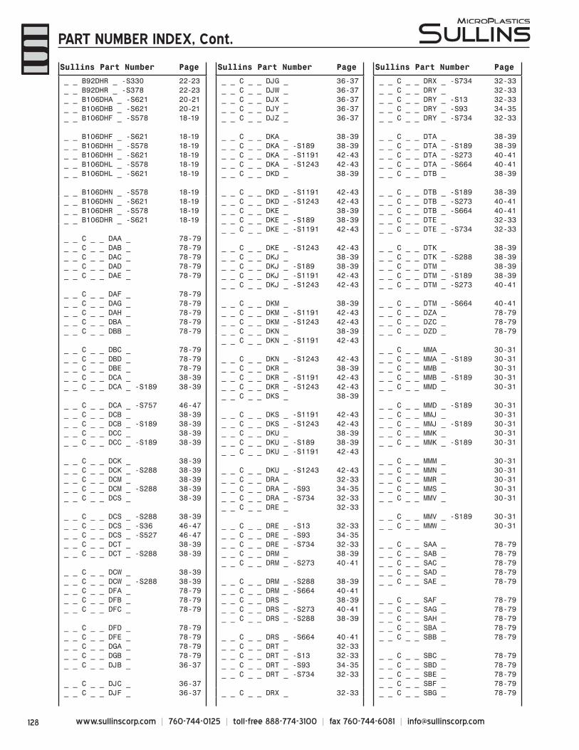
www.sullinscorp.com | 760-744-0125 | toll-free 888-774-3100 | fax 760-744-6081 | [email protected]
Sullins Part Number Page Sullins Part Number Page Sullins Part Number Page
_ _ B92DHR _ -S330 22-23 _ _ C _ _ DJG _ 36-37 _ _ C _ _ DRX _ -S734 32-33_ _ B92DHR _ -S378 22-23 _ _ C _ _ DJW _ 36-37 _ _ C _ _ DRY _ 32-33_ _ B106DHA _ -S621 20-21 _ _ C _ _ DJX _ 36-37 _ _ C _ _ DRY _ -S13 32-33_ _ B106DHB _ -S621 20-21 _ _ C _ _ DJY _ 36-37 _ _ C _ _ DRY _ -S93 34-35_ _ B106DHF _ -S578 18-19 _ _ C _ _ DJZ _ 36-37 _ _ C _ _ DRY _ -S734 32-33
_ _ B106DHF _ -S621 18-19 _ _ C _ _ DKA _ 38-39 _ _ C _ _ DTA _ 38-39_ _ B106DHH _ -S578 18-19 _ _ C _ _ DKA _ -S189 38-39 _ _ C _ _ DTA _ -S189 38-39_ _ B106DHH _ -S621 18-19 _ _ C _ _ DKA _ -S1191 42-43 _ _ C _ _ DTA _ -S273 40-41_ _ B106DHL _ -S578 18-19 _ _ C _ _ DKA _ -S1243 42-43 _ _ C _ _ DTA _ -S664 40-41_ _ B106DHL _ -S621 18-19 _ _ C _ _ DKD _ 38-39 _ _ C _ _ DTB _ 38-39
_ _ B106DHN _ -S578 18-19 _ _ C _ _ DKD _ -S1191 42-43 _ _ C _ _ DTB _ -S189 38-39_ _ B106DHN _ -S621 18-19 _ _ C _ _ DKD _ -S1243 42-43 _ _ C _ _ DTB _ -S273 40-41_ _ B106DHR _ -S578 18-19 _ _ C _ _ DKE _ 38-39 _ _ C _ _ DTB _ -S664 40-41_ _ B106DHR _ -S621 18-19 _ _ C _ _ DKE _ -S189 38-39 _ _ C _ _ DTE _ 32-33
_ _ C _ _ DKE _ -S1191 42-43 _ _ C _ _ DTE _ -S734 32-33_ _ C _ _ DAA _ 78-79_ _ C _ _ DAB _ 78-79 _ _ C _ _ DKE _ -S1243 42-43 _ _ C _ _ DTK _ 38-39_ _ C _ _ DAC _ 78-79 _ _ C _ _ DKJ _ 38-39 _ _ C _ _ DTK _ -S288 38-39_ _ C _ _ DAD _ 78-79 _ _ C _ _ DKJ _ -S189 38-39 _ _ C _ _ DTM _ 38-39_ _ C _ _ DAE _ 78-79 _ _ C _ _ DKJ _ -S1191 42-43 _ _ C _ _ DTM _ -S189 38-39
_ _ C _ _ DKJ _ -S1243 42-43 _ _ C _ _ DTM _ -S273 40-41_ _ C _ _ DAF _ 78-79_ _ C _ _ DAG _ 78-79 _ _ C _ _ DKM _ 38-39 _ _ C _ _ DTM _ -S664 40-41_ _ C _ _ DAH _ 78-79 _ _ C _ _ DKM _ -S1191 42-43 _ _ C _ _ DZA _ 78-79_ _ C _ _ DBA _ 78-79 _ _ C _ _ DKM _ -S1243 42-43 _ _ C _ _ DZC _ 78-79_ _ C _ _ DBB _ 78-79 _ _ C _ _ DKN _ 38-39 _ _ C _ _ DZD _ 78-79
_ _ C _ _ DKN _ -S1191 42-43_ _ C _ _ DBC _ 78-79 _ _ C _ _ MMA _ 30-31_ _ C _ _ DBD _ 78-79 _ _ C _ _ DKN _ -S1243 42-43 _ _ C _ _ MMA _ -S189 30-31_ _ C _ _ DBE _ 78-79 _ _ C _ _ DKR _ 38-39 _ _ C _ _ MMB _ 30-31_ _ C _ _ DCA _ 38-39 _ _ C _ _ DKR _ -S1191 42-43 _ _ C _ _ MMB _ -S189 30-31_ _ C _ _ DCA _ -S189 38-39 _ _ C _ _ DKR _ -S1243 42-43 _ _ C _ _ MMD _ 30-31
_ _ C _ _ DKS _ 38-39_ _ C _ _ DCA _ -S757 46-47 _ _ C _ _ MMD _ -S189 30-31_ _ C _ _ DCB _ 38-39 _ _ C _ _ DKS _ -S1191 42-43 _ _ C _ _ MMJ _ 30-31_ _ C _ _ DCB _ -S189 38-39 _ _ C _ _ DKS _ -S1243 42-43 _ _ C _ _ MMJ _ -S189 30-31_ _ C _ _ DCC _ 38-39 _ _ C _ _ DKU _ 38-39 _ _ C _ _ MMK _ 30-31_ _ C _ _ DCC _ -S189 38-39 _ _ C _ _ DKU _ -S189 38-39 _ _ C _ _ MMK _ -S189 30-31
_ _ C _ _ DKU _ -S1191 42-43_ _ C _ _ DCK _ 38-39 _ _ C _ _ MMM _ 30-31_ _ C _ _ DCK _ -S288 38-39 _ _ C _ _ DKU _ -S1243 42-43 _ _ C _ _ MMN _ 30-31_ _ C _ _ DCM _ 38-39 _ _ C _ _ DRA _ 32-33 _ _ C _ _ MMR _ 30-31_ _ C _ _ DCM _ -S288 38-39 _ _ C _ _ DRA _ -S93 34-35 _ _ C _ _ MMS _ 30-31 _ _ C _ _ DCS _ 38-39 _ _ C _ _ DRA _ -S734 32-33 _ _ C _ _ MMV _ 30-31
_ _ C _ _ DRE _ 32-33_ _ C _ _ DCS _ -S288 38-39 _ _ C _ _ MMV _ -S189 30-31_ _ C _ _ DCS _ -S36 46-47 _ _ C _ _ DRE _ -S13 32-33 _ _ C _ _ MMW _ 30-31_ _ C _ _ DCS _ -S527 46-47 _ _ C _ _ DRE _ -S93 34-35_ _ C _ _ DCT _ 38-39 _ _ C _ _ DRE _ -S734 32-33 _ _ C _ _ SAA _ 78-79_ _ C _ _ DCT _ -S288 38-39 _ _ C _ _ DRM _ 38-39 _ _ C _ _ SAB _ 78-79
_ _ C _ _ DRM _ -S273 40-41 _ _ C _ _ SAC _ 78-79_ _ C _ _ DCW _ 38-39 _ _ C _ _ SAD _ 78-79_ _ C _ _ DCW _ -S288 38-39 _ _ C _ _ DRM _ -S288 38-39 _ _ C _ _ SAE _ 78-79_ _ C _ _ DFA _ 78-79 _ _ C _ _ DRM _ -S664 40-41_ _ C _ _ DFB _ 78-79 _ _ C _ _ DRS _ 38-39 _ _ C _ _ SAF _ 78-79_ _ C _ _ DFC _ 78-79 _ _ C _ _ DRS _ -S273 40-41 _ _ C _ _ SAG _ 78-79
_ _ C _ _ DRS _ -S288 38-39 _ _ C _ _ SAH _ 78-79_ _ C _ _ DFD _ 78-79 _ _ C _ _ SBA _ 78-79_ _ C _ _ DFE _ 78-79 _ _ C _ _ DRS _ -S664 40-41 _ _ C _ _ SBB _ 78-79_ _ C _ _ DGA _ 78-79 _ _ C _ _ DRT _ 32-33_ _ C _ _ DGB _ 78-79 _ _ C _ _ DRT _ -S13 32-33 _ _ C _ _ SBC _ 78-79_ _ C _ _ DJB _ 36-37 _ _ C _ _ DRT _ -S93 34-35 _ _ C _ _ SBD _ 78-79
_ _ C _ _ DRT _ -S734 32-33 _ _ C _ _ SBE _ 78-79_ _ C _ _ DJC _ 36-37 _ _ C _ _ SBF _ 78-79_ _ C _ _ DJF _ 36-37 _ _ C _ _ DRX _ 32-33 _ _ C _ _ SBG _ 78-79
PART NUMBER INDEX, Cont.
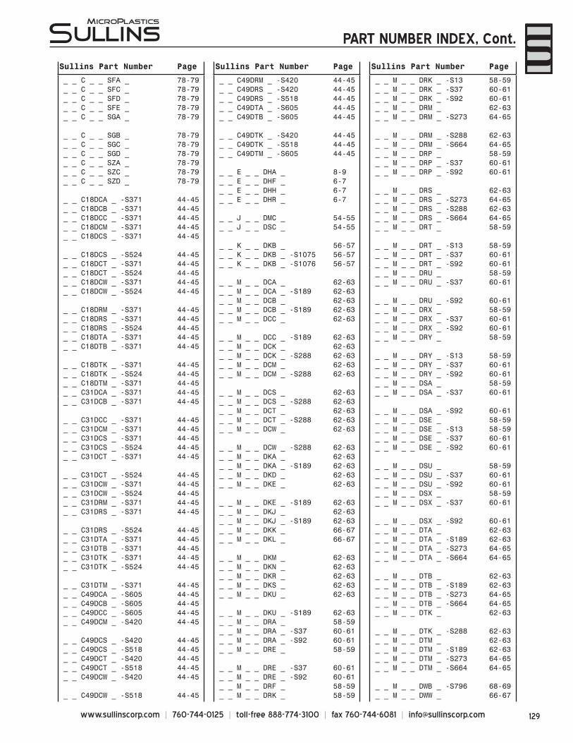
129www.sullinscorp.com | 760-744-0125 | toll-free 888-774-3100 | fax 760-744-6081 | [email protected]
Sullins Part Number Page Sullins Part Number Page Sullins Part Number Page
_ _ C _ _ SFA _ 78-79 _ _ C49DRM _ -S420 44-45 _ _ M _ _ DRK _ -S13 58-59_ _ C _ _ SFC _ 78-79 _ _ C49DRS _ -S420 44-45 _ _ M _ _ DRK _ -S37 60-61_ _ C _ _ SFD _ 78-79 _ _ C49DRS _ -S518 44-45 _ _ M _ _ DRK _ -S92 60-61_ _ C _ _ SFE _ 78-79 _ _ C49DTA _ -S605 44-45 _ _ M _ _ DRM _ 62-63_ _ C _ _ SGA _ 78-79 _ _ C49DTB _ -S605 44-45 _ _ M _ _ DRM _ -S273 64-65
_ _ C _ _ SGB _ 78-79 _ _ C49DTK _ -S420 44-45 _ _ M _ _ DRM _ -S288 62-63_ _ C _ _ SGC _ 78-79 _ _ C49DTK _ -S518 44-45 _ _ M _ _ DRM _ -S664 64-65_ _ C _ _ SGD _ 78-79 _ _ C49DTM _ -S605 44-45 _ _ M _ _ DRP _ 58-59_ _ C _ _ SZA _ 78-79 _ _ M _ _ DRP _ -S37 60-61_ _ C _ _ SZC _ 78-79 _ _ E _ _ DHA _ 8-9 _ _ M _ _ DRP _ -S92 60-61_ _ C _ _ SZD _ 78-79 _ _ E _ _ DHF _ 6-7
_ _ E _ _ DHH _ 6-7 _ _ M _ _ DRS _ 62-63_ _ C18DCA _ -S371 44-45 _ _ E _ _ DHR _ 6-7 _ _ M _ _ DRS _ -S273 64-65_ _ C18DCB _ -S371 44-45 _ _ M _ _ DRS _ -S288 62-63_ _ C18DCC _ -S371 44-45 _ _ J _ _ DMC _ 54-55 _ _ M _ _ DRS _ -S664 64-65_ _ C18DCM _ -S371 44-45 _ _ J _ _ DSC _ 54-55 _ _ M _ _ DRT _ 58-59_ _ C18DCS _ -S371 44-45
_ _ K _ _ DKB _ 56-57 _ _ M _ _ DRT _ -S13 58-59_ _ C18DCS _ -S524 44-45 _ _ K _ _ DKB _ -S1075 56-57 _ _ M _ _ DRT _ -S37 60-61_ _ C18DCT _ -S371 44-45 _ _ K _ _ DKB _ -S1076 56-57 _ _ M _ _ DRT _ -S92 60-61_ _ C18DCT _ -S524 44-45 _ _ M _ _ DRU _ 58-59_ _ C18DCW _ -S371 44-45 _ _ M _ _ DCA _ 62-63 _ _ M _ _ DRU _ -S37 60-61_ _ C18DCW _ -S524 44-45 _ _ M _ _ DCA _ -S189 62-63
_ _ M _ _ DCB _ 62-63 _ _ M _ _ DRU _ -S92 60-61_ _ C18DRM _ -S371 44-45 _ _ M _ _ DCB _ -S189 62-63 _ _ M _ _ DRX _ 58-59_ _ C18DRS _ -S371 44-45 _ _ M _ _ DCC _ 62-63 _ _ M _ _ DRX _ -S37 60-61_ _ C18DRS _ -S524 44-45 _ _ M _ _ DRX _ -S92 60-61_ _ C18DTA _ -S371 44-45 _ _ M _ _ DCC _ -S189 62-63 _ _ M _ _ DRY _ 58-59_ _ C18DTB _ -S371 44-45 _ _ M _ _ DCK _ 62-63
_ _ M _ _ DCK _ -S288 62-63 _ _ M _ _ DRY _ -S13 58-59_ _ C18DTK _ -S371 44-45 _ _ M _ _ DCM _ 62-63 _ _ M _ _ DRY _ -S37 60-61_ _ C18DTK _ -S524 44-45 _ _ M _ _ DCM _ -S288 62-63 _ _ M _ _ DRY _ -S92 60-61_ _ C18DTM _ -S371 44-45 _ _ M _ _ DSA _ 58-59_ _ C31DCA _ -S371 44-45 _ _ M _ _ DCS _ 62-63 _ _ M _ _ DSA _ -S37 60-61_ _ C31DCB _ -S371 44-45 _ _ M _ _ DCS _ -S288 62-63
_ _ M _ _ DCT _ 62-63 _ _ M _ _ DSA _ -S92 60-61_ _ C31DCC _ -S371 44-45 _ _ M _ _ DCT _ -S288 62-63 _ _ M _ _ DSE _ 58-59_ _ C31DCM _ -S371 44-45 _ _ M _ _ DCW _ 62-63 _ _ M _ _ DSE _ -S13 58-59_ _ C31DCS _ -S371 44-45 _ _ M _ _ DSE _ -S37 60-61_ _ C31DCS _ -S524 44-45 _ _ M _ _ DCW _ -S288 62-63 _ _ M _ _ DSE _ -S92 60-61_ _ C31DCT _ -S371 44-45 _ _ M _ _ DKA _ 62-63
_ _ M _ _ DKA _ -S189 62-63 _ _ M _ _ DSU _ 58-59_ _ C31DCT _ -S524 44-45 _ _ M _ _ DKD _ 62-63 _ _ M _ _ DSU _ -S37 60-61_ _ C31DCW _ -S371 44-45 _ _ M _ _ DKE _ 62-63 _ _ M _ _ DSU _ -S92 60-61_ _ C31DCW _ -S524 44-45 _ _ M _ _ DSX _ 58-59_ _ C31DRM _ -S371 44-45 _ _ M _ _ DKE _ -S189 62-63 _ _ M _ _ DSX _ -S37 60-61_ _ C31DRS _ -S371 44-45 _ _ M _ _ DKJ _ 62-63
_ _ M _ _ DKJ _ -S189 62-63 _ _ M _ _ DSX _ -S92 60-61_ _ C31DRS _ -S524 44-45 _ _ M _ _ DKK _ 66-67 _ _ M _ _ DTA _ 62-63_ _ C31DTA _ -S371 44-45 _ _ M _ _ DKL _ 66-67 _ _ M _ _ DTA _ -S189 62-63_ _ C31DTB _ -S371 44-45 _ _ M _ _ DTA _ -S273 64-65_ _ C31DTK _ -S371 44-45 _ _ M _ _ DKM _ 62-63 _ _ M _ _ DTA _ -S664 64-65_ _ C31DTK _ -S524 44-45 _ _ M _ _ DKN _ 62-63
_ _ M _ _ DKR _ 62-63 _ _ M _ _ DTB _ 62-63_ _ C31DTM _ -S371 44-45 _ _ M _ _ DKS _ 62-63 _ _ M _ _ DTB _ -S189 62-63_ _ C49DCA _ -S605 44-45 _ _ M _ _ DKU _ 62-63 _ _ M _ _ DTB _ -S273 64-65_ _ C49DCB _ -S605 44-45 _ _ M _ _ DTB _ -S664 64-65_ _ C49DCC _ -S605 44-45 _ _ M _ _ DKU _ -S189 62-63 _ _ M _ _ DTK _ 62-63_ _ C49DCM _ -S420 44-45 _ _ M _ _ DRA _ 58-59
_ _ M _ _ DRA _ -S37 60-61 _ _ M _ _ DTK _ -S288 62-63_ _ C49DCS _ -S420 44-45 _ _ M _ _ DRA _ -S92 60-61 _ _ M _ _ DTM _ 62-63_ _ C49DCS _ -S518 44-45 _ _ M _ _ DRE _ 58-59 _ _ M _ _ DTM _ -S189 62-63_ _ C49DCT _ -S420 44-45 _ _ M _ _ DTM _ -S273 64-65_ _ C49DCT _ -S518 44-45 _ _ M _ _ DRE _ -S37 60-61 _ _ M _ _ DTM _ -S664 64-65_ _ C49DCW _ -S420 44-45 _ _ M _ _ DRE _ -S92 60-61
_ _ M _ _ DRF _ 58-59 _ _ M _ _ DWB _ -S796 68-69_ _ C49DCW _ -S518 44-45 _ _ M _ _ DRK _ 58-59 _ _ M _ _ DWW _ 66-67
PART NUMBER INDEX, Cont.
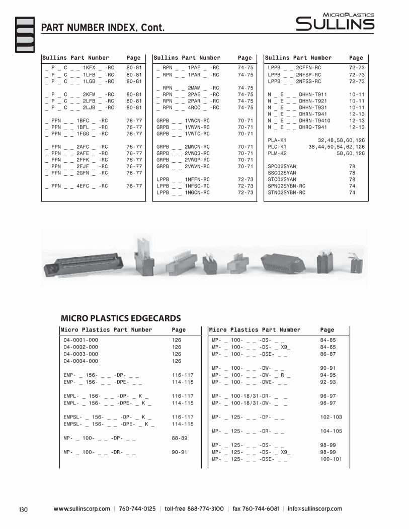
www.sullinscorp.com | 760-744-0125 | toll-free 888-774-3100 | fax 760-744-6081 | [email protected]
MICRO PLASTICS EDGECARDSMicro Plastics Part Number Page Micro Plastics Part Number Page
04-0001-000 126 MP- _ 100- _ _ -DS- _ _ 84-8504-0002-000 126 MP- _ 100- _ _ -DS- _ X9_ 84-8504-0003-000 126 MP- _ 100- _ _ -DSE- _ _ 86-8704-0004-000 126
MP- _ 100- _ _ -DW- _ _ 90-91EMP- _ 156- _ _ -DP- _ _ 116-117 MP- _ 100- _ _ -DW- _ R _ 94-95EMP- _ 156- _ _ -DPE- _ _ 114-115 MP- _ 100- _ _ -DWE- _ _ 92-93
EMPL- _ 156- _ _ -DP- _ K _ 116-117 MP- _ 100-18/31-DR- _ _ 96-97EMPL- _ 156- _ _ -DPE- _ K _ 114-115 MP- _ 100-18/31-DW- _ _ 96-97
EMPSL- _ 156- _ _ -DP- _ K _ 116-117 MP- _ 125- _ _ -DP- _ _ 102-103EMPSL- _ 156- _ _ -DPE- _ K _ 114-115
MP- _ 125- _ _ -DR- _ _ 104-105MP- _ 100- _ _ -DP- _ _ 88-89
MP- _ 125- _ _ -DS- _ _ 98-99MP- _ 100- _ _ -DR- _ _ 90-91 MP- _ 125- _ _ -DS- _ X9_ 98-99
MP- _ 125- _ _ -DSE- _ _ 100-101
PART NUMBER INDEX, Cont.
Sullins Part Number Page Sullins Part Number Page Sullins Part Number Page
_ P _ C _ _ 1KFX _ -RC 80-81 _ RPN _ _ 1PAE _ -RC 74-75 LPPB _ _ 2CFFN-RC 72-73_ P _ C _ _ 1LFB _ -RC 80-81 _ RPN _ _ 1PAR _ -RC 74-75 LPPB _ _ 2NFSP-RC 72-73_ P _ C _ _ 1LGB _ -RC 80-81 LPPB _ _ 2NFSS-RC 72-73
_ RPN _ _ 2MAM _ -RC 74-75_ P _ C _ _ 2KFM _ -RC 80-81 _ RPN _ _ 2PAE _ -RC 74-75 N _ E _ _ DHHN-T911 10-11_ P _ C _ _ 2LFB _ -RC 80-81 _ RPN _ _ 2PAR _ -RC 74-75 N _ E _ _ DHHN-T921 10-11_ P _ C _ _ 2LJB _ -RC 80-81 _ RPN _ _ 4RCC _ -RC 74-75 N _ E _ _ DHHN-T931 10-11
N _ E _ _ DHRN-T941 12-13_ PPN _ _ 1BFC _ -RC 76-77 GRPB _ _ 1VWCN-RC 70-71 N _ E _ _ DHRN-T9410 12-13_ PPN _ _ 1BFL _ -RC 76-77 GRPB _ _ 1VWVN-RC 70-71 N _ E _ _ DHRQ-T941 12-13_ PPN _ _ 1FGG _ -RC 76-77 GRPB _ _ 1VWTC-RC 70-71
PLA-K1 32,48,58,60,126_ PPN _ _ 2AFC _ -RC 76-77 GRPB _ _ 2MWCN-RC 70-71 PLC-K1 38,44,50,54,62,126_ PPN _ _ 2AFE _ -RC 76-77 GRPB _ _ 2VWQS-RC 70-71 PLM-K2 58,60,126 _ PPN _ _ 2FFK _ -RC 76-77 GRPB _ _ 2VWQP-RC 70-71_ PPN _ _ 2FJF _ -RC 76-77 GRPB _ _ 2VWVN-RC 70-71 SPC02SYAN 78_ PPN _ _ 2GFN _ -RC 76-77 SSC02SYAN 78
LPPB _ _ 1NFFN-RC 72-73 STC02SYAN 78_ PPN _ _ 4EFC _ -RC 76-77 LPPB _ _ 1NFSC-RC 72-73 SPN02SYBN-RC 74
LPPB _ _ 1NGCN-RC 72-73 STN02SYBN-RC 74
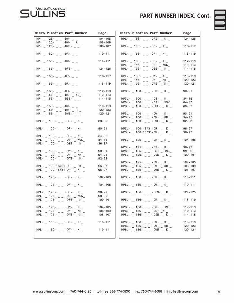
131www.sullinscorp.com | 760-744-0125 | toll-free 888-774-3100 | fax 760-744-6081 | [email protected]
Micro Plastics Part Number Page Micro Plastics Part Number Page
MP- _ 125- _ _ -DW- _ _ 104-105 MPL- _ 156- _ _ -DFS- _ K _ 124-125MP- _ 125- _ _ -DW- _ R _ 108-109MP- _ 125- _ _ -DWE- _ _ 106-107 MPL- _ 156- _ _ -DP- _ K _ 116-117
MP- _ 150- _ _ -DR- _ _ 110-111 MPL- _ 156- _ _ -DR- _ K _ 118-119
MP- _ 150- _ _ -DW- _ _ 110-111 MPL- _ 156- _ _ -DS- _ K _ 112-113MPL- _ 156- _ _ -DS- _ X9K_ 112-113
MP- _ 156- _ _ -DFS- _ _ 124-125 MPL- _ 156- _ _ -DSE- _ K _ 114-115
MP- _ 156- _ _ -DP- _ _ 116-117 MPL- _ 156- _ _ -DW- _ K _ 118-119MPL- _ 156- _ _ -DW- _ KR _ 122-123
MP- _ 156- _ _ -DR- _ _ 118-119 MPL- _ 156- _ _ -DWE- _ K _ 120-121
MP- _ 156- _ _ -DS- _ _ 112-113 MPSL- _ 100- _ _ -DR- _ K _ 90-91MP- _ 156- _ _ -DS- _ X9_ 112-113MP- _ 156- _ _ -DSE- _ _ 114-115 MPSL- _ 100- _ _ -DS- _ K _ 84-85
MPSL- _ 100- _ _ -DS- _ X9K_ 84-85MP- _ 156- _ _ -DW- _ _ 118-119 MPSL- _ 100- _ _ -DSE- _ K _ 86-87MP- _ 156- _ _ -DW- _ R _ 122-123MP- _ 156- _ _ -DWE- _ _ 120-121 MPSL- _ 100- _ _ -DW- _ K _ 90-91
MPSL- _ 100- _ _ -DW- _ KR _ 94-95MPL- _ 100- _ _ -DP- _ K _ 88-89 MPSL- _ 100- _ _ -DWE- _ K _ 92-93
MPL- _ 100- _ _ -DR- _ K _ 90-91 MPSL- _ 100-18/31-DR- _ K _ 96-97MPSL- _ 100-18/31-DW- _ K _ 96-97
MPL- _ 100- _ _ -DS- _ K _ 84-85MPL- _ 100- _ _ -DS- _ X9K_ 84-85 MPSL- _ 125- _ _ -DR- _ K _ 104-105MPL- _ 100- _ _ -DSE- _ K _ 86-87
MPSL- _ 125- _ _ -DS- _ K _ 98-99MPL- _ 100- _ _ -DW- _ K _ 90-91 MPSL- _ 125- _ _ -DS- _ X9K_ 98-99MPL- _ 100- _ _ -DW- _ KR _ 94-95 MPSL- _ 125- _ _ -DSE- _ K _ 100-101MPL- _ 100- _ _ -DWE- _ K _ 92-93
MPSL- _ 125- _ _ -DW- _ K _ 104-105MPL- _ 100-18/31-DR- _ K _ 96-97 MPSL- _ 125- _ _ -DW- _ KR _ 108-109MPL- _ 100-18/31-DW- _ K _ 96-97 MPSL- _ 125- _ _ -DWE- _ K _ 106-107
MPL- _ 125- _ _ -DP- _ K _ 102-103 MPSL- _ 150- _ _ -DR- _ K _ 110-111
MPL- _ 125- _ _ -DR- _ K _ 104-105 MPSL- _ 150- _ _ -DW- _ K_ 110-111
MPL- _ 125- _ _ -DS- _ K _ 98-99 MPSL- _ 156- _ _ -DFS- _ K _ 124-125MPL- _ 125- _ _ -DS- _ X9K_ 98-99MPL- _ 125- _ _ -DSE- _ K _ 100-101 MPSL- _ 156- _ _ -DR- _ K _ 118-119
MPL- _ 125- _ _ -DW- _ K _ 104-105 MPSL- _ 156- _ _ -DS- _ X9K_ 112-113MPL- _ 125- _ _ -DW- _ KR _ 108-109 MPSL- _ 156- _ _ -DS- _K _ 112-113MPL- _ 125- _ _ -DWE- _ K _ 106-107 MPSL- _ 156- _ _ -DSE- _ K _ 114-115
MPL- _ 150- _ _ -DR- _ K _ 110-111 MPSL- _ 156- _ _ -DW- _ K _ 118-119MPSL- _ 156- _ _ -DW- _ KR _ 122-123
MPL- _ 150- _ _ -DW- _ K _ 110-111 MPSL- _ 156- _ _ -DWE- _ K _ 120-121
PART NUMBER INDEX, Cont.
www.sullinscorp.com | 760-744-0125 | toll-free 888-774-3100 | fax 760-744-6081 | [email protected]
A BRAND NEW SULLINS2008 is an exciting year for Sullins as we strive to become a more customer-driven and competitive company offering a wider spectrum of products and services than ever before. To achieve this goal, we are rebranding our company from the inside out. In the coming months, you’ll be experiencing some new and revitalized results of our rebranding efforts in your interactions with Sullins. Below are just a few highlights we’d like to share with you:
New LogoSullins’ fresh new logo symbolizes our transformation into a more modern and streamlined company in order to serve customers like you more effectively. Our new tagline, “Connector Solutions” brings more focus and clarity in communicating our business to all audiences.
New CatalogOur 2008 catalog is the largest ever, combining products from Sullins and Micro Plastics into one convenient reference. We hope our newly designed, comprehensive catalog is easy to use and provides all the information you need for your connector solutions.
New Web Site — Coming Summer 2008Sullins is developing a brand new Web site to communicate and conduct business more effectively with online customers. The new, invigorated design will help online customers navigate the site easily, learn about new products better, fi nd products quickly, understand our connector design process more thoroughly, purchase standard connectors from our online store, and much, much more!
GO THE DISTANCEAt Sullins, we go the distance to meet our customers’ needs. But don’t take our word for it. Here are what some customers have to say about our products and services.
“You are awesome. I can always count on you to have the quotes in an hour or two. You are timely and effi cient, a pleasure to do business with.”
-Jackie Feight, Heilind Electronics
“Sullins’ response turnaround, accuracy and attention to detail is beyond impressive. Simply amazing!”
-Paul Alexandrescu, Product Cost Engineering
“Man that was fast! Like how you work, girl. THANKS!!!!!!”-Johnny Q. Guerrero, Ital Electronics
“You’re the best.”-Erik Wisesa, Bisco Industries
WE VALUE YOUR FEEDBACKYour input is important to us as we continue to grow and become a better company. Please feel free to share any notable feedback or suggestions with us by e-mailing [email protected].
WHAT’S NEXT?
Recommended