Stix and Drums LLC 1990 N. McCulloch Blvd. Ste. D222 Lake Havasu City, AZ Voice: 928.733.6002 Fax: [email protected] www.stixanddrums.com
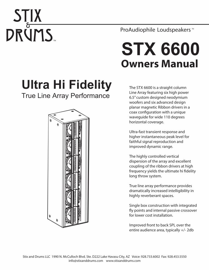
The STX 6600 is a straight column Line Array featuring six high power 6.5” custom designed neodymium woofers and six advanced design planar magnetic Ribbon drivers in a coax con�guration with a uniquewaveguide for wide 110 degrees horizontal coverage.
Ultra-fast transient response and higher instantaneous peak level for faithful signal reproduction and improved dynamic range.
The highly controlled vertical dispersion of the array and excellent coupling of the ribbon drivers at high frequency yields the ultimate hi �delity long throw system.
True line array performance provides dramatically increased intelligibility in highly reverberant spaces.
Single box construction with integrated �y points and internal passive crossover for lower cost installation.
Improved front to back SPL over the entire audience area, typically +/- 2db
Introduction
Thank you for choosing Stix & Drums. When your speakers are installed and used properly, you can expectexceptional aural performance and years of trouble free service. Please read this manual thoroughly prior to installation.
Information in this guide is meant only for the purpose of using the AmbiSonic Systems supplied mounting equipment. All other rigging and/or structure support including wall securing hardware is considered part of the venue and/or end-user supplied equipment and is not addressed in this guide.
AmbiSonic Systems assumes that a working knowledge of accepted rigging practices and safety will be applied to all rigging materials and practices employed. All rigging or wall mounting should be performed by a professional installer or installation company and should follow all state and local building codes. All fasteners should be rated at a minimum of 3-5 times the actual determined load. All walls are not created equal (drywall, masonry, wood, etc.) In some instances it will be necessary to install “Backing” plates or other reinforcement to assure proper mounting.
Remember that the weakest component determines the safety of the entire rigging assembly. Prior to securing the array, always inspect all hardware components for wear, deformations, corrosion and missing or damaged parts. Also confirm that the venue attachment points are suitably load rated for the array. No information contained in this guide is intended as a warranty on the part of AmbiSonic Systems.
Users assume all responsibility for the appropriate use of AmbiSonic Systems supplied rigging hardware and follow at a minimum all applicable laws and regulations in force for each venue.
Anyone using this information assumes all liability arising from it’s use. Product abuse, use of the product not in accordance with AmbiSonic Systems instructions or use in an application which the product has not been designed for is not covered under any AmbiSonic Systems warranty nor is AmbiSonic Systems liable for any loss or damage.
Safety Responsibilities and Liability
Stix and Drums LLC 1990 N. McCulloch Blvd. Ste. D222 Lake Havasu City, AZ Voice: 928.733.6002 Fax: [email protected] www.stixanddrums.com
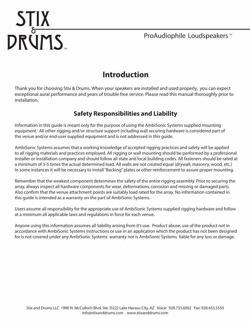
Attach the coupling plates with theremoved M10 flathead screws
Attaching Coupling Brackets (BKT-CP66)
Remove the M10 Flathead Screws(4 places each side)
Coupling Brackets(BKT-CP66) (2)
All attachment points for coupling brackets are reinforced with internal steel brackets for maximum strength and reliability.
For multiple stacked arrays
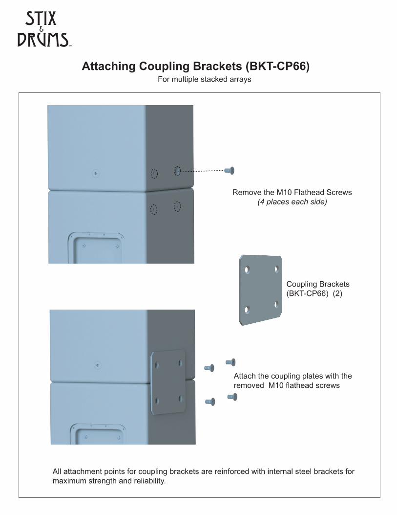
Wall Mounting Kit (BKT-WM66)
Upper Bracket
Pivot Left Pin
Pivot Right Pin
Rotation Locking Fastener
Wall Mounting Bracket
Down-angle adjustment holes
Upper Bracket Assembly
Lower Bracket Assembly
Pivot Right Pin
Wall Mounting Bracket
Rotation Locking Fastener
Pivot Left Pin
Lower Bracket
Pivot Hole
For multiple stacked arrays
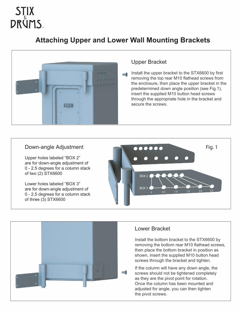
Attaching Upper and Lower Wall Mounting Brackets
Upper Bracket
Install the upper bracket to the STX6600 by firstremoving the top rear M10 flathead screws from the enclosure, then place the upper bracket in thepredetermined down angle position (see Fig.1), insert the supplied M10 button head screwsthrough the appropriate hole in the bracket and secure the screws.
BOX 2
BOX 30 0.5 1.0 1.5 2.0 2.5
Fig. 1Down-angle Adjustment
Upper holes labeled “BOX 2”are for down-angle adjustment of0 - 2.5 degrees for a column stackof two (2) STX6600
Lower holes labeled “BOX 3”are for down-angle adjustment of 0 - 2.5 degrees for a column stack of three (3) STX6600
Install the bottom bracket to the STX6600 byremoving the bottom rear M10 flathead screws,then place the bottom bracket in position as shown, insert the supplied M10 button headscrews through the bracket and tighten.
If the column will have any down angle, thescrews should not be tightened completelyas they are the pivot point for rotation. Once the column has been mounted and adjusted for angle, you can then tightenthe pivot screws.
Lower Bracket
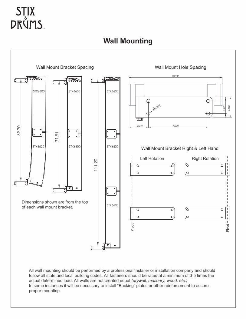
Wall Mounting
Wall Mount Bracket Right & Left Hand
Left Rotation Right Rotation
Pivo
t
Pivo
t
7.000
1.4
62
2.4
62
2.277
0.397
10.945
Wall Mount Hole Spacing
71.
91
111
.20
69.
70
Dimensions shown are from the top of each wall mount bracket.
STX6620
STX6600 STX6600
STX6600
STX6600
STX6600
STX6600
Wall Mount Bracket Spacing
All wall mounting should be performed by a professional installer or installation company and shouldfollow all state and local building codes. All fasteners should be rated at a minimum of 3-5 times the actual determined load. All walls are not created equal (drywall, masonry, wood, etc.) In some instances it will be necessary to install “Backing” plates or other reinforcement to assureproper mounting.
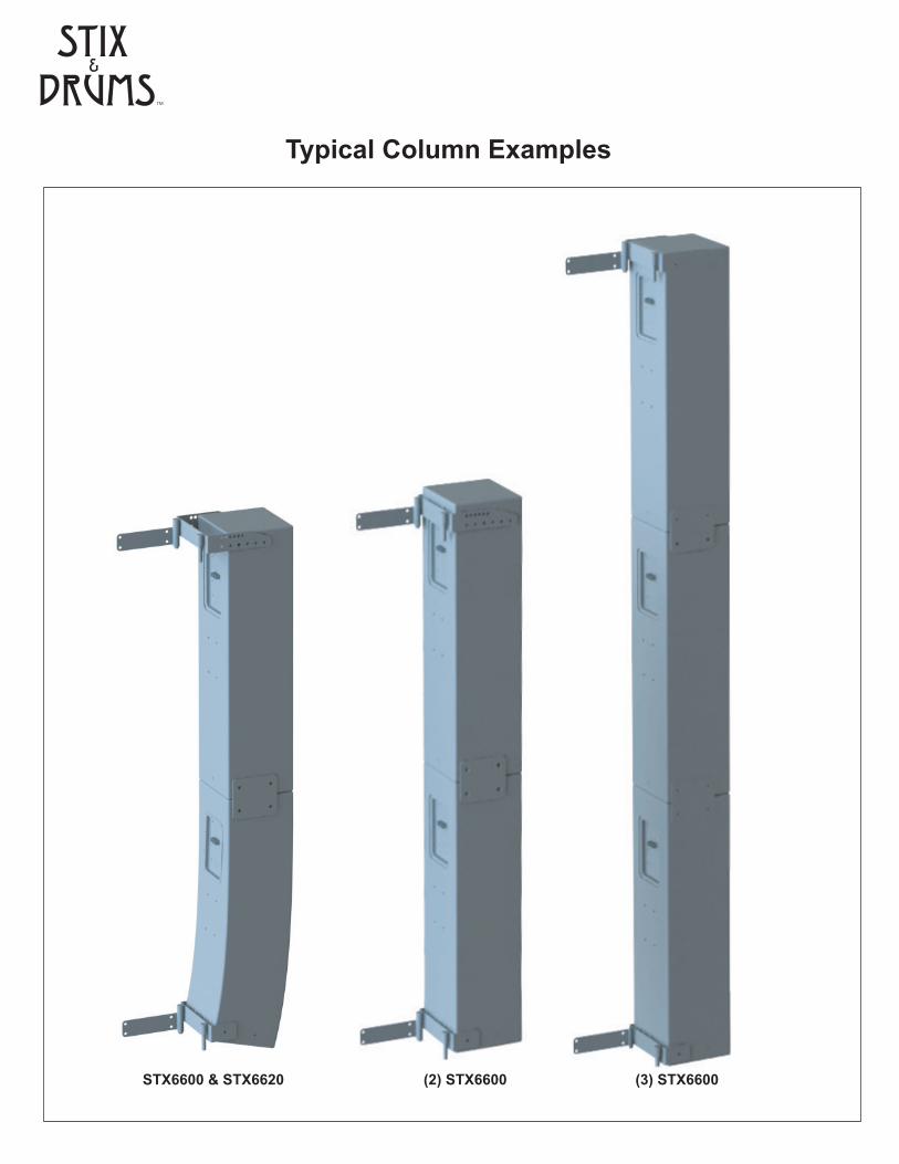
Typical Column Examples
STX6600 & STX6620 (2) STX6600 (3) STX6600
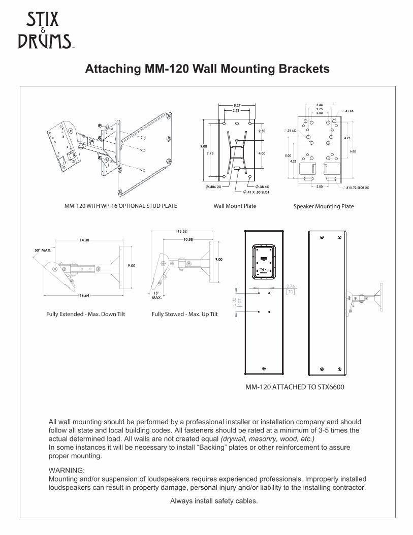
Attaching MM-120 Wall Mounting Brackets
2X.406
9.00
5.27
4X.38
3.75
7.75
2.50
4.00
.41 X .50 SLOT
Wall Mount Plate
Fully Extended - Max. Down Tilt Fully Stowed - Max. Up Tilt
FULLY EXTENDED ARM AT MAX. DOWN TILT ANGLE
14.38
9.00
16.64
50° MAX.
MAX.
10.88
13.52
15°
9.00
FULLY STOWED ARM AT MAX. UP TILT ANGLE
6.88
3.44
X.72 SLOT 2X.41
4.25
2.00
5.00
2.00
2.75
4.25
4X.41
.39 6X
Speaker Mounting PlateMM-120 WITH WP-16 OPTIONAL STUD PLATE
MM-120 ATTACHED TO STX6600
2.7670
5.
0012
7
Always install safety cables.
All wall mounting should be performed by a professional installer or installation company and shouldfollow all state and local building codes. All fasteners should be rated at a minimum of 3-5 times the actual determined load. All walls are not created equal (drywall, masonry, wood, etc.) In some instances it will be necessary to install “Backing” plates or other reinforcement to assureproper mounting.
WARNING: Mounting and/or suspension of loudspeakers requires experienced professionals. Improperly installed loudspeakers can result in property damage, personal injury and/or liability to the installing contractor.
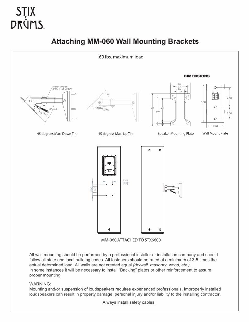
Attaching MM-060 Wall Mounting Brackets
1.56
3.75
6.00
5.00
2.752.00
4.25
.50 .88
Speaker Mounting Plate
DIMENSIONS
45 degrees Max. Down Tilt 45 degress Max. Up Tilt
@45 DEGREE TILT
NYLON WASHER3/8 ID X 1.25 OD (2X)
MAX45°
2.25
45°
Wall Mount Plate
REAR MOUNTED ILLUSTRATION (8" ARM TUBE)
REVISIONS
ZONE REV. DESCRIPTION DRAWN DATE APPROVED
01REVISED CABLE PAS THRU HOLE
LOCATIONS. ADDED BOTTOM MOUNTED ILLUSTRATIONS. ADDED WALL PLATE
COVERTBA 04/30/13
02 REVISED WALL PLATE ASSY AND COVER TBA 05/08/13
USE AND SALE RIGHTS REGARDING THE SAME
UNLESS OTHERWISE SPECIFIED:
Unless Otherwise Specified
E:\ENGINEERING\PROJECTS-PRELIMINARY DRAWINGS\PROJ-301-UP\PROJ-502 MULTIMOUNT 24 NEW GENERATION\
THIRD ANGLE PROJECTION
A
B
C
D
4
DO NOT SCALE DRAWING
8 7 6
EXPRESSLY RESERVED BY ALLEN PRODUCTS
8
PRODUCTS CO. AND EMBODIES A PROPRIETY
7 56
NOT BE REPRODUCED OR INFORMATION ARE EXPRESSLY RESERVED. THIS DRAWING MAY
ALL DESIGN, MANUFACTURE, REPRODUCTION,
THREE PLACE DECIMAL
5 4
THIS DRAWING IS THE PROPERTY OF ALLEN
HEREIN TRANSMITTED IN ANY WAY WITHOUTWRITTEN CONSENT FROM ALLEN PRODUCTSCO. ALL PATENT RIGHTS HERETO ARE
CO. SIGNAL HILL, CALIFORNIA
PROPRIETARY AND CONFIDENTIAL
FILE LOCATION:
MATERIAL
FINISH
TOLERANCING PER:
DESIGN ORIGINATED BY ALLEN PRODUCTS CO.
INTERPRET GEOMETRIC
DIMENSIONS ARE IN INCHESTOLERANCES:FRACTIONALANGULAR: MACHTWO PLACE DECIMAL
Notes:
2-7088
SPEAKER ADAPTER PLATE 2-7086
THREADED ROD
1/8" THICK STEEL PLATE PIVOT BRACKET2-7090
PIVOT U-BRACKET
FOR REAR AND
SCREWED TO TUBE
BOTTOM MOUNTED
1.75 SQ X .12 TUBE
2-7095
2-7097TRUSS HEAD BINDING POST SCREW
3/8" DIA. BARREL X 2.063" LONGX 1/4-20 THREAD
2.25
12.00
7.25
1.88
2.00
4.25 6.00
5.00
2.753.75
2.50
8.004.00
3.58
2.7570
5.
0012
7
MM-060 ATTACHED TO STX6600
Always install safety cables.
All wall mounting should be performed by a professional installer or installation company and shouldfollow all state and local building codes. All fasteners should be rated at a minimum of 3-5 times the actual determined load. All walls are not created equal (drywall, masonry, wood, etc.) In some instances it will be necessary to install “Backing” plates or other reinforcement to assureproper mounting.
60 lbs. maximum load
WARNING: Mounting and/or suspension of loudspeakers requires experienced professionals. Improperly installed loudspeakers can result in property damage, personal injury and/or liability to the installing contractor.
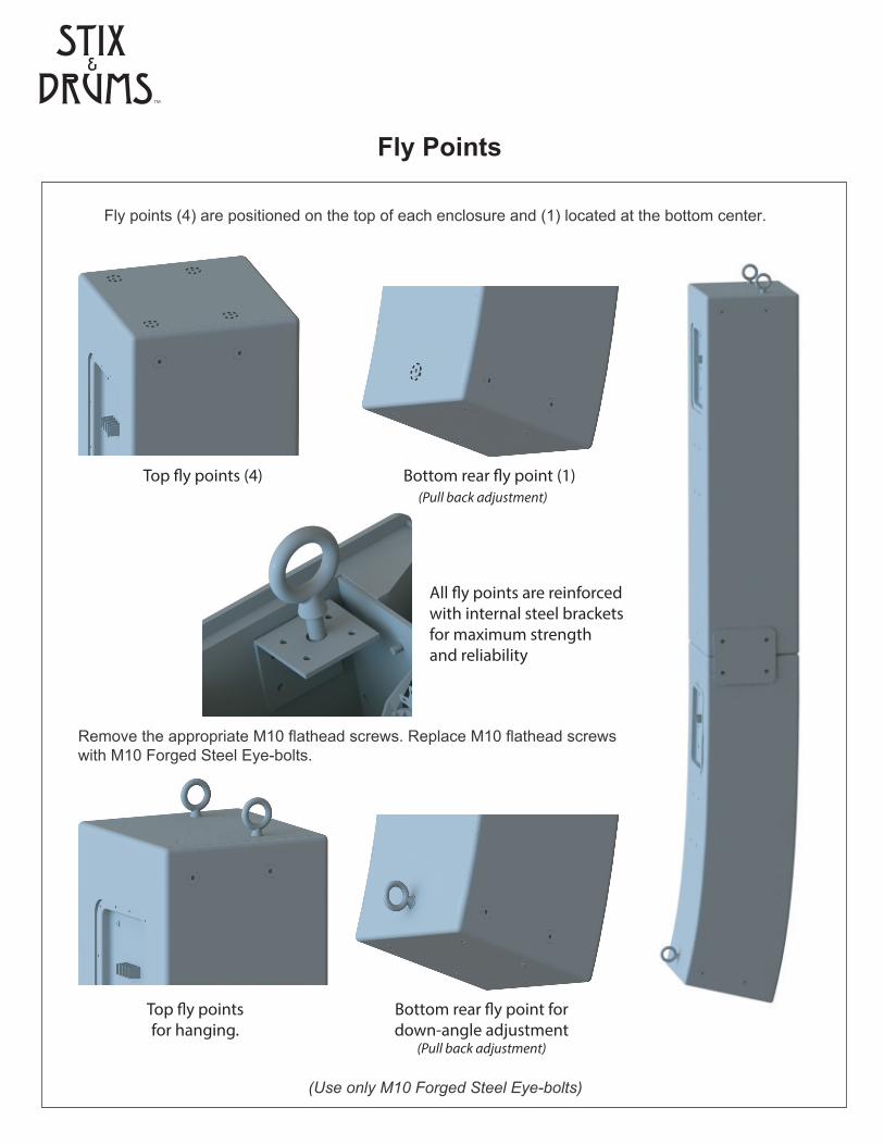
Fly Points
(Use only M10 Forged Steel Eye-bolts)
Remove the appropriate M10 flathead screws. Replace M10 flathead screws with M10 Forged Steel Eye-bolts.
Top �y points (4) Bottom rear �y point (1) (Pull back adjustment)
All �y points are reinforcedwith internal steel bracketsfor maximum strengthand reliability
Top �y pointsfor hanging.
Bottom rear �y point fordown-angle adjustment
(Pull back adjustment)
Fly points (4) are positioned on the top of each enclosure and (1) located at the bottom center.
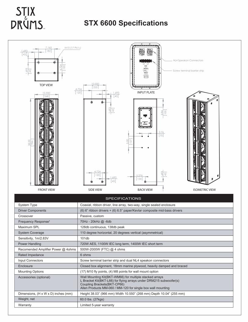
STX 6600 Specifications
Sensitivity, 1m/2.83V
Power Handling
Recomended Amplifier Power @ 4ohms
Rated Impedance
Input Connectors
Enclosure
Mounting Options
101db
720W AES, 1100W IEC long term, 1400W IEC short term
500W-2000W (FTC) @ 4 ohms
6 ohms
Screw terminal barrier strip and dual NL4 speakon connectors
Closed box alignment, 18mm marine plywood, heavily damped and braced
(17) M10 fly points, (4) M8 points for wall mount option
System Type
Driver Components
Crossover
Maximum SPL
Coaxial, ribbon driver, line array, two-way, single sealed enclosure
(6) 6” ribbon drivers + (6) 6.5” paper/Kevlar composite mid-bass drivers
Passive, custom
70Hz - 20kHz @ -6db
128db continuous, 138db peak
SPECIFICATIONS
System Coverage 110 degree horizontal, 20 degrees vertical (asymmetrical)
10.550268
38
.00
966
FRONT VIEW
10.000255
1.69343
4.724120
1.6
9343
1.69343
4.724120
SIDE VIEW
2.7670
5.276134
5.
0012
7
1.6
9343
3.
94
100
BACK VIEW ISOMETRIC VIEW
1.69343
7.165
182
1.6
9343
4.7
2412
0
TOP VIEW
M10 (17 Plc's.)
Accessories (optional) Wall Mounting Kit(BKT-WM66) for multiple stacked arrays L Bracket Kit(BKT-L66) for flying arrays under DRM215 subwoofer(s) Coupling Brackets(BKT-CP66) Allen Products MM-060 / MM-120 for single box wall mounting
Dimensions, (H x W x D) inches (mm)Weight, net
Warranty
Height 38.03” (966 mm) Width 10.550” (268 mm) Depth 10.04” (255 mm)
60.0 lbs. (27kgs)
Limited 5-year warranty
Frequency Response¹
Input4ohms
LoopOutput
TM
SubwooferModel STX 6600
Made in Phillppines
- - ++
By
Input Loop Output
NL4 Speakon Connectors
Screw terminal barrier strip
INPUT PLATE
Ambisonic Systems LLC (Ambisonic) Warranty on Stix & Drums ‘Products’ is in e�ect for a period of 5 years from the date of �rst consumer purchase. Except as outlined below, your Stix & Drums Warranty covers all defects in material and workmanship as long as the product is properly used and maintained.
If the Product is deemed defective by Ambisonic, Ambisonic will at its option, repair or replace the Product. If the defective Product cannot be repaired or is no longer available for replacement, Ambisonic may replace the Product with a current equivalent model of equal or greater value.
Under terms of this Warranty, the Product must be returned to an authorized Stix & Drums dealer or Ambisonic. Return shipping and associated costs for exchanges or repairs is the sole responsibility of the original purchaser.
Limitations:
This limited Warranty does not cover failure of the Product resulting from improper installation, misuse, abuse, accident, neglect, mishandling, or wear and tear from ordinary use or environmental deterioration.
This limited Warranty does not cover cosmetic damage, including paint damage, or consequential damage to the other components or premises which may result for any reason from the failure of the Product.
This limited Warranty is null and void for Products not used in accordance with Ambisonic’s instructions.
This limited Warranty is null and void for Products with altered or missing serial numbers and for Products not purchased from an authorized Stix & Drums dealer.
This limited Warranty terminates if you sell or otherwise transfer this Product to another party.
Warranty
Stix and Drums LLC 1990 N. McCulloch Blvd. Ste. D222 Lake Havasu City, AZ Voice: 928.733.6002 Fax: [email protected] www.stixanddrums.com
Recommended