STM32F4 family – practical session
Atollic TrueSTUDIO STM32
+ STM32F4 discovery kit
modified by www.emcu.it
www.emcu.it
Before the training
Select/configure PC with MS Windows 2000/XP/Vista/7 in order to have
administrative rights (required by ST-Link programmer/debugger)
Install the current version of Atollic TrueSTUDIO STM32
Prepare USB cable type A to mini-B
Prepare STM32F4_Discovery board.
Check whether there are no updates for ST-Link programmer/debugger
available on www.st.com/stm32f4-discovery web page
www.emcu.it
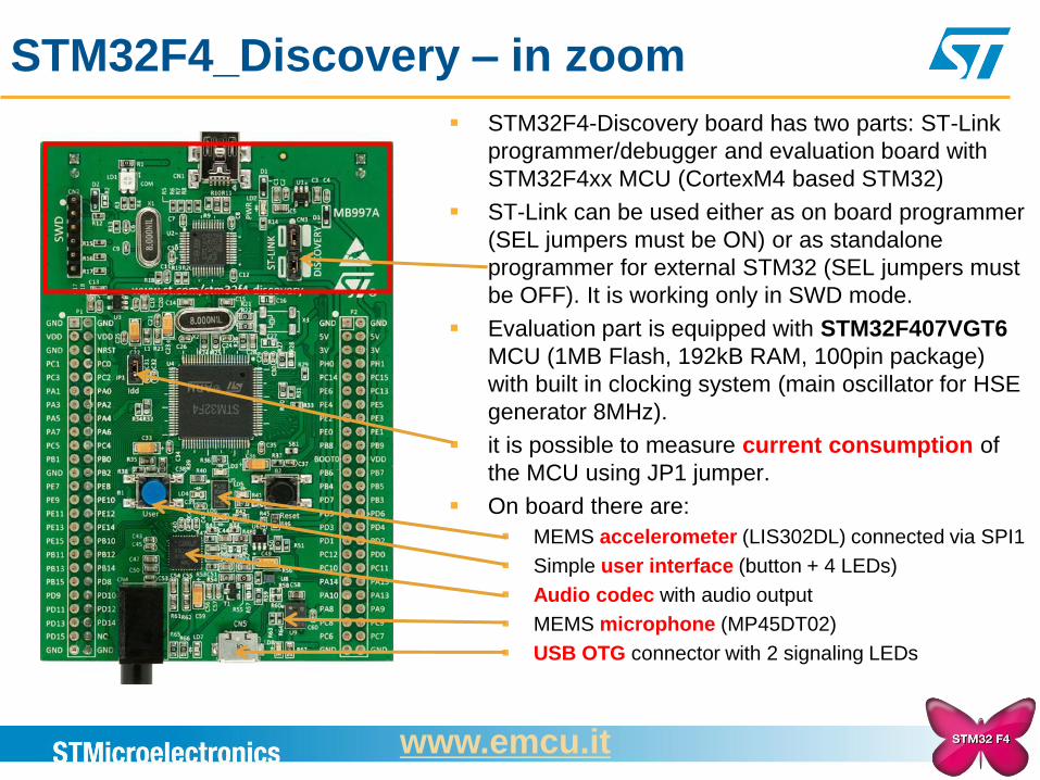
STM32F4_Discovery – in zoom
STM32F4-Discovery board has two parts: ST-Link
programmer/debugger and evaluation board with
STM32F4xx MCU (CortexM4 based STM32)
ST-Link can be used either as on board programmer
(SEL jumpers must be ON) or as standalone
programmer for external STM32 (SEL jumpers must
be OFF). It is working only in SWD mode.
Evaluation part is equipped with STM32F407VGT6
MCU (1MB Flash, 192kB RAM, 100pin package)
with built in clocking system (main oscillator for HSE
generator 8MHz).
it is possible to measure current consumption of
the MCU using JP1 jumper.
On board there are:
MEMS accelerometer (LIS302DL) connected via SPI1
Simple user interface (button + 4 LEDs)
Audio codec with audio output
MEMS microphone (MP45DT02)
USB OTG connector with 2 signaling LEDs
www.emcu.it
Atollic TrueSTUDIO/STM32
INTRODUCTION
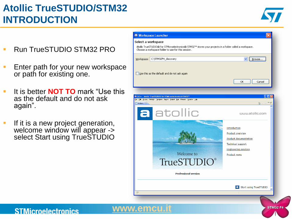
Run TrueSTUDIO STM32 PRO
Enter path for your new workspace or path for existing one.
It is better NOT TO mark “Use this as the default and do not ask again”.
If it is a new project generation, welcome window will appear -> select Start using TrueSTUDIO
www.emcu.it
Atollic TrueSTUDIO/STM32
Import existing project (.ZIP) to workspace
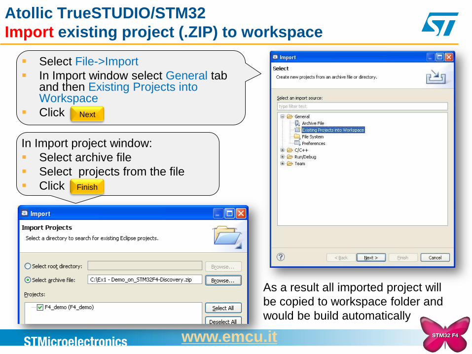
As a result all imported project will
be copied to workspace folder and
would be build automatically
Select File->Import
In Import window select General tab and then Existing Projects into Workspace
Click Next
In Import project window:
Select archive file
Select projects from the file
Click Finish
www.emcu.it
Atollic TrueSTUDIO/STM32
Export existing project to archive (.ZIP)
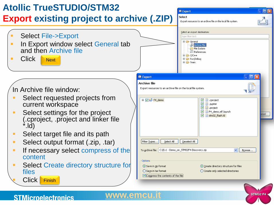
In Archive file window:
Select requested projects from current workspace
Select settings for the project (.cproject, .project and linker file *.ld)
Select target file and its path
Select output format (.zip, .tar)
If necessary select compress of the content
Select Create directory structure for files
Click
Select File->Export
In Export window select General tab and then Archive file
Click Next
Finish
www.emcu.it
Atollic TrueSTUDIO/STM32
Project – file structure
After create new project dedicated to one of the boards following file structure will be
visible in project explorer: Binaries
Includes
Utilities -> procedures to handle GUI on eval board
src -> main source directory (main.c – main.h – etc)
Libraries -> ST and CMSIS libraries
CMSIS
STM32F4xx_StdPeriph_Driver
Debug
Physically on HDD project folder, there will be following subdirectories: .metadata – main configuration of the workspace.
<Prj_name> -> main prj dir including sources, linker file (*.ld), object files and executables
.coverage -> used for code coverage analysis (not available in Lite version)
.settings -> used for hardware details concerning used MCU, eval board and programmer/debugger
Debug -> object files, executables of the project
Libraries
Utilities
src
When using remote sources (link to external sources) only .settings and Debug
folders are present.
www.emcu.it
Atollic TrueSTUDIO/STM32
Project – file structure operations
Easiest way to add new .c file to the project is just copy it to one of source directories.
Files will be detected automatically by the toolchain and will be included to compiler
and linker files. Other methods are source files import or create remote link.
Project Explorer important options are valid for files and directories (mouse right
button):
Exclude from build can be used to not to build part of the code
Delete physically removes all selected sources and its headers from project
directory on HDD
Import physically copies selected files to project directory
Open/create new project in the same workspace using code generator will create the
same folder structure including another copy of libraries. To avoid this we can use link
to remote sources option.
www.emcu.it
Atollic TrueSTUDIO/STM32
Tasks editor features
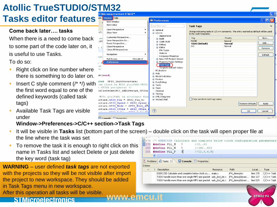
Come back later…. tasks
When there is a need to come back
to some part of the code later on, it
is useful to use Tasks.
To do so:
Right click on line number where
there is something to do later on.
Insert C style comment (/* */) with
the first word equal to one of the
defined keywords (called task
tags)
Available Task Tags are visible
under
Window->Preferences->C/C++ section->Task Tags
It will be visible in Tasks list (bottom part of the screen) – double click on the task will open proper file at
the line where the task was set
To remove the task it is enough to right click on this
name in Tasks list and select Delete or just delete
the key word (task tag)
WARNING – user defined task tags are not exported
with the projects so they will be not visible after import
the project to new workspace. They should be added
in Task Tags menu in new workspace.
After this operation all tasks will be visible. www.emcu.it
Atollic TrueSTUDIO/STM32
Build the project and configure debug session
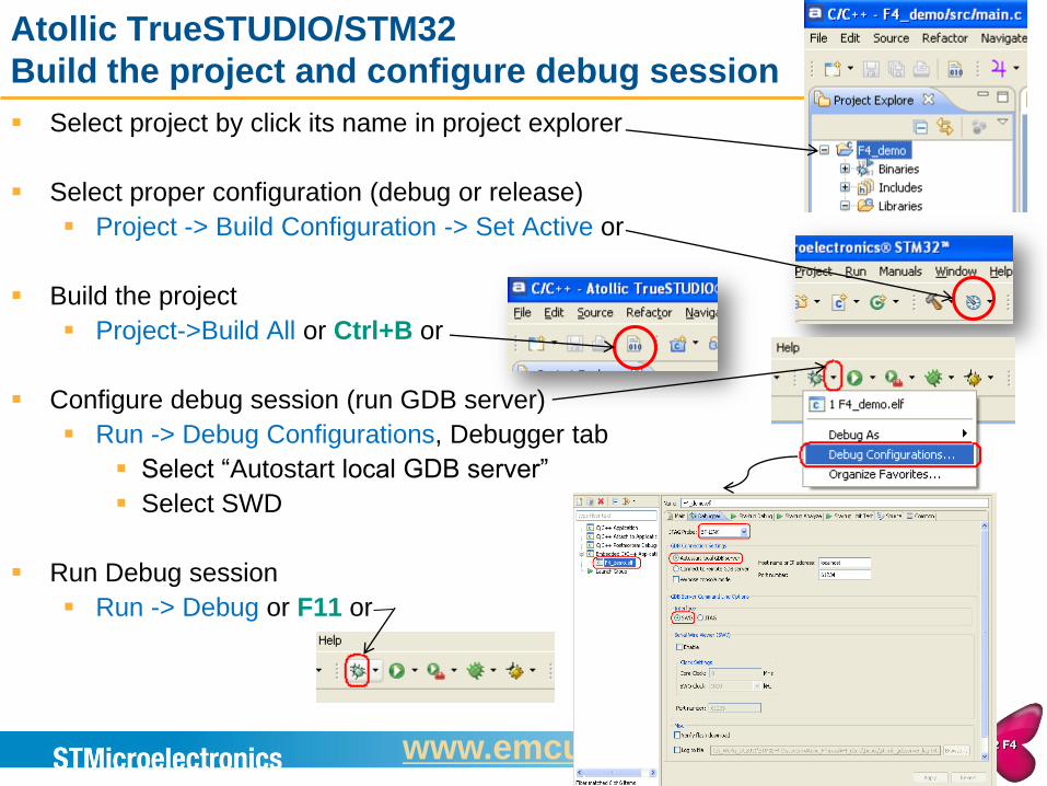
Select project by click its name in project explorer
Select proper configuration (debug or release)
Project -> Build Configuration -> Set Active or
Build the project
Project->Build All or Ctrl+B or
Configure debug session (run GDB server)
Run -> Debug Configurations, Debugger tab
Select “Autostart local GDB server”
Select SWD
Run Debug session
Run -> Debug or F11 or
www.emcu.it
Atollic TrueSTUDIO/STM32
Run debug session
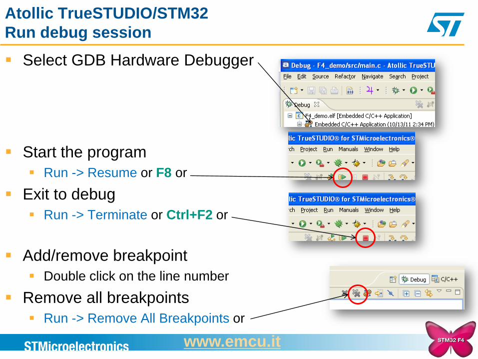
Select GDB Hardware Debugger
Start the program
Run -> Resume or F8 or
Exit to debug
Run -> Terminate or Ctrl+F2 or
Add/remove breakpoint
Double click on the line number
Remove all breakpoints
Run -> Remove All Breakpoints or
www.emcu.it
Atollic TrueSTUDIO/STM32
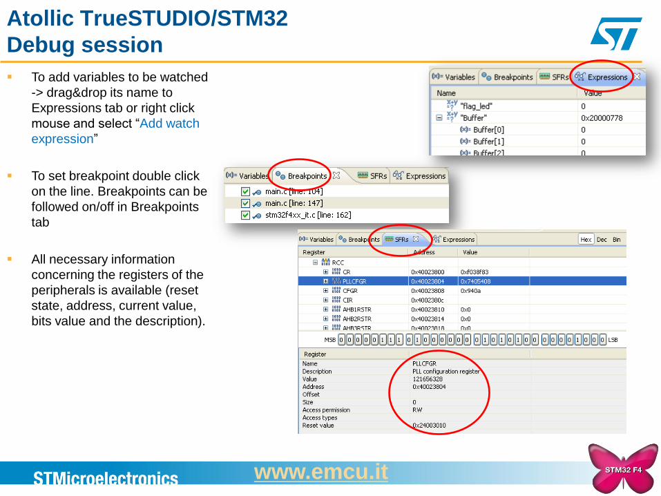
Debug session
To add variables to be watched
-> drag&drop its name to
Expressions tab or right click
mouse and select “Add watch
expression”
To set breakpoint double click
on the line. Breakpoints can be
followed on/off in Breakpoints
tab
All necessary information
concerning the registers of the
peripherals is available (reset
state, address, current value,
bits value and the description).
www.emcu.it
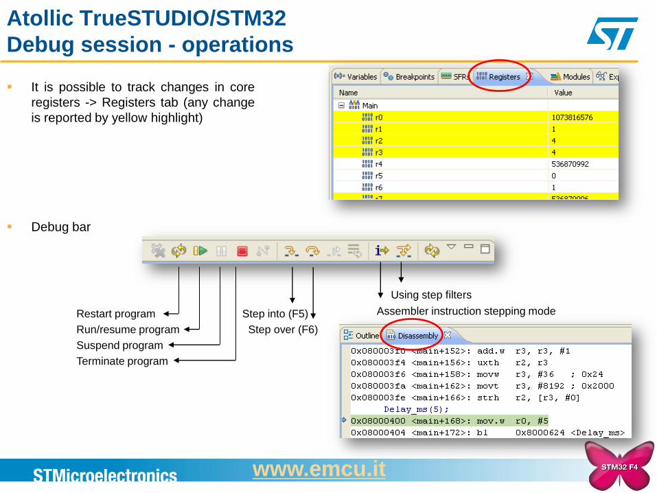
Atollic TrueSTUDIO/STM32
Debug session - operations
It is possible to track changes in core
registers -> Registers tab (any change
is reported by yellow highlight)
Debug bar
Restart program
Run/resume program
Suspend program
Terminate program
Step into (F5)
Step over (F6)
Using step filters
Assembler instruction stepping mode
www.emcu.it
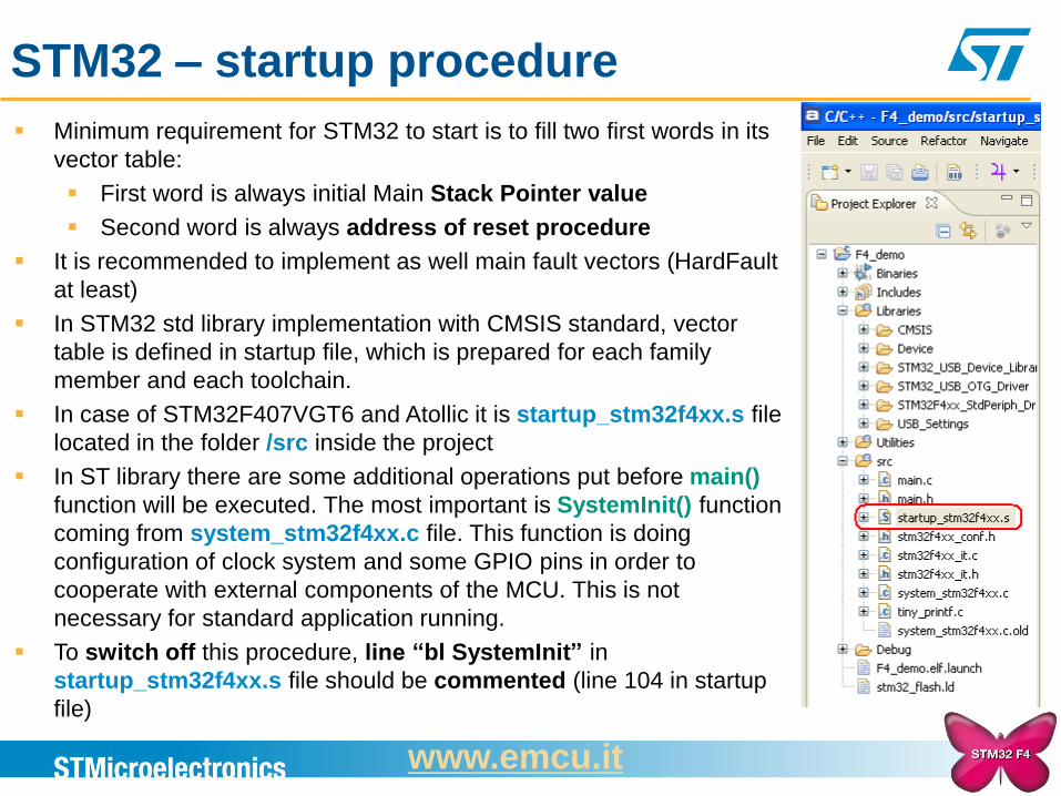
STM32 – startup procedure
Minimum requirement for STM32 to start is to fill two first words in its
vector table:
First word is always initial Main Stack Pointer value
Second word is always address of reset procedure
It is recommended to implement as well main fault vectors (HardFault
at least)
In STM32 std library implementation with CMSIS standard, vector
table is defined in startup file, which is prepared for each family
member and each toolchain.
In case of STM32F407VGT6 and Atollic it is startup_stm32f4xx.s file
located in the folder /src inside the project
In ST library there are some additional operations put before main()
function will be executed. The most important is SystemInit() function
coming from system_stm32f4xx.c file. This function is doing
configuration of clock system and some GPIO pins in order to
cooperate with external components of the MCU. This is not
necessary for standard application running.
To switch off this procedure, line “bl SystemInit” in
startup_stm32f4xx.s file should be commented (line 104 in startup
file)
www.emcu.it
15
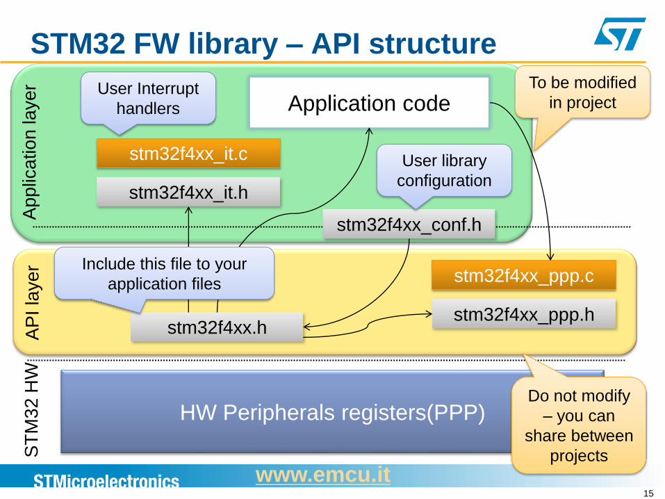
STM32 FW library – API structure
Application code
stm32f4xx_it.c
stm32f4xx_it.h
stm32f4xx.h stm32f4xx_ppp.h
stm32f4xx_ppp.c
HW Peripherals registers(PPP)
stm32f4xx_conf.h
Ap
plic
atio
n la
ye
r
AP
I la
ye
r
ST
M3
2 H
W
User Interrupt
handlers
User library
configuration
Include this file to your
application files
To be modified
in project
Do not modify
– you can
share between
projects
www.emcu.it
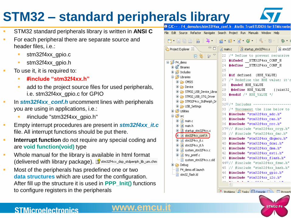
STM32 – standard peripherals library STM32 standard peripherals library is written in ANSI C
For each peripheral there are separate source and
header files, i.e.:
stm32f4xx_gpio.c
stm32f4xx_gpio.h
To use it, it is required to:
#include “stm32f4xx.h”
add to the project source files for used peripherals,
i.e. stm32f4xx_gpio.c for GPIO
In stm32f4xx_conf.h uncomment lines with peripherals
you are using in applications, i.e.:
#include "stm32f4xx_gpio.h"
Empty interrupt procedures are present in stm32f4xx_it.c
file. All interrupt functions should be put there.
Interrupt function do not require any special coding and
are void function(void) type
Whole manual for the library is available in html format
(delivered with library package).
Most of the peripherals has predefined one or two
data structures which are used for the configuration.
After fill up the structure it is used in PPP_Init() functions
to configure registers in the peripherals
www.emcu.it
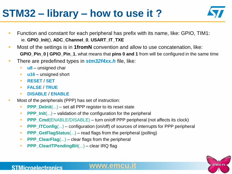
STM32 – library – how to use it ?
Function and constant for each peripheral has prefix with its name, like: GPIO, TIM1:
ie. GPIO_Init(), ADC_Channel_0, USART_IT_TXE Most of the settings is in 1fromN convention and allow to use concatenation, like:
GPIO_Pin_0 | GPIO_Pin_1, what means that pins 0 and 1 from will be configured in the same time
There are predefined types in stm32f4xx.h file, like:
u8 – unsigned char
u16 – unsigned short
RESET / SET
FALSE / TRUE
DISABLE / ENABLE
Most of the peripherals (PPP) has set of instruction:
PPP_DeInit(...) – set all PPP register to its reset state
PPP_Init(...) – validation of the configuration for the peripheral
PPP_Cmd(ENABLE/DISABLE) – turn on/off PPP peripheral (not affects its clock)
PPP_ITConfig(...) – configuration (on/off) of sources of interrupts for PPP peripheral
PPP_GetFlagStatus(...) – read flags from the peripheral (polling)
PPP_ClearFlag(...) – clear flags from the peripheral
PPP_ClearITPendingBit(...) – clear IRQ flag
www.emcu.it
STM32 – library - FAQ
1. Compiler is reporting a lot of errors like:
Missing prototype
GPIO_Pin_0 undefined
Solution
Please check whether in stm32f4xx_conf.h all used library modules are
uncommented
Please check, whether USE_STDPERIPH_DRIVER constant is defined in your
environment
2. Linker is reporting a lot of errors like:
Lab_library.lkf:1 symbol _GPIO_WriteHigh not defined (Debug/main.o)
Solution
Please check whether all library source files are added, stm32f4xx_gpio.c in this
case.
www.emcu.it
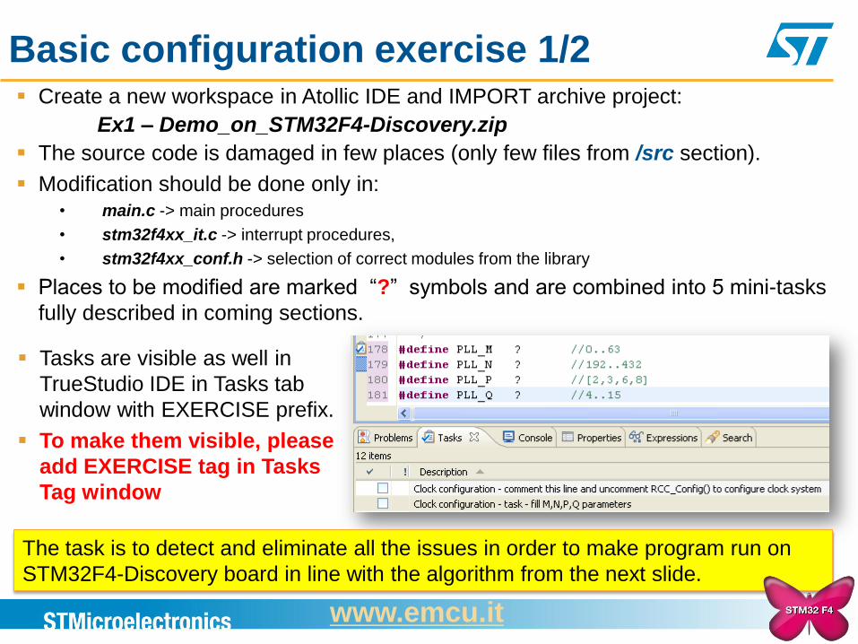
Basic configuration exercise 1/2 Create a new workspace in Atollic IDE and IMPORT archive project:
Ex1 – Demo_on_STM32F4-Discovery.zip
The source code is damaged in few places (only few files from /src section).
Modification should be done only in: • main.c -> main procedures
• stm32f4xx_it.c -> interrupt procedures,
• stm32f4xx_conf.h -> selection of correct modules from the library
Places to be modified are marked “?” symbols and are combined into 5 mini-tasks
fully described in coming sections.
Tasks are visible as well in
TrueStudio IDE in Tasks tab
window with EXERCISE prefix.
To make them visible, please
add EXERCISE tag in Tasks
Tag window
The task is to detect and eliminate all the issues in order to make program run on
STM32F4-Discovery board in line with the algorithm from the next slide.
www.emcu.it
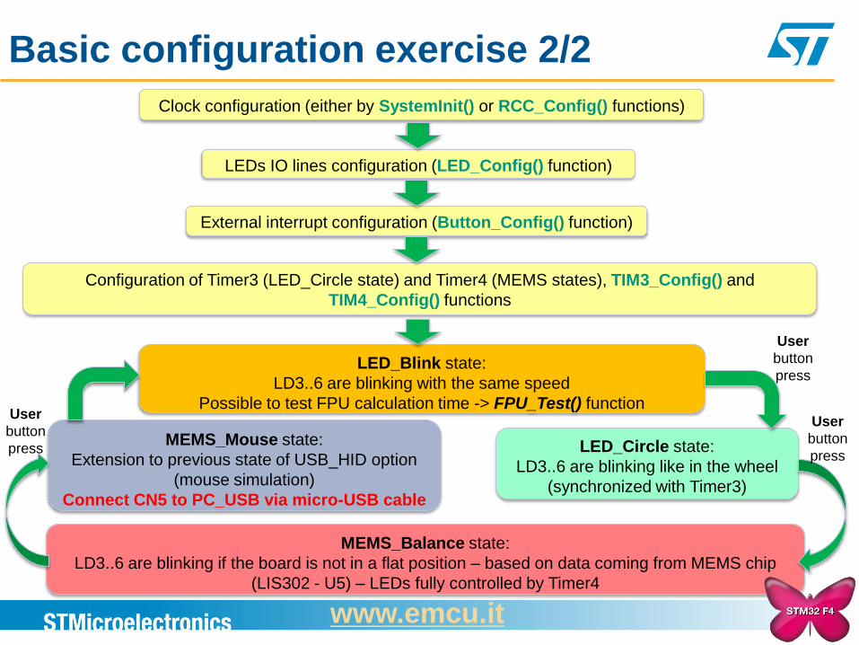
Basic configuration exercise 2/2
Clock configuration (either by SystemInit() or RCC_Config() functions)
LEDs IO lines configuration (LED_Config() function)
External interrupt configuration (Button_Config() function)
Configuration of Timer3 (LED_Circle state) and Timer4 (MEMS states), TIM3_Config() and
TIM4_Config() functions
LED_Blink state:
LD3..6 are blinking with the same speed
Possible to test FPU calculation time -> FPU_Test() function
LED_Circle state:
LD3..6 are blinking like in the wheel
(synchronized with Timer3)
MEMS_Mouse state:
Extension to previous state of USB_HID option
(mouse simulation)
Connect CN5 to PC_USB via micro-USB cable
MEMS_Balance state:
LD3..6 are blinking if the board is not in a flat position – based on data coming from MEMS chip
(LIS302 - U5) – LEDs fully controlled by Timer4
User
button
press
User
button
press
User
button
press
www.emcu.it
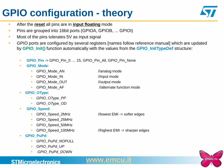
GPIO configuration - theory After the reset all pins are in input floating mode
Pins are grouped into 16bit ports (GPIOA, GPIOB, ... GPIOI)
Most of the pins tolerates 5V as input signal
GPIO ports are configured by several registers [names follow reference manual] which are updated
by GPIO_Init() function automatically with the values from the GPIO_InitTypeDef structure:
GPIO_Pin -> GPIO_Pin_0 .... 15, GPIO_Pin_All, GPIO_Pin_None
GPIO_Mode:
GPIO_Mode_AN //analog mode
GPIO_Mode_IN //input mode
GPIO_Mode_OUT //output mode
GPIO_Mode_AF //alternate function mode
GPIO_OType:
GPIO_OType_PP
GPIO_OType_OD
GPIO_Speed:
GPIO_Speed_2MHz //lowest EMI -> softer edges
GPIO_Speed_25MHz
GPIO_Speed_50MHz
GPIO_Speed_100MHz //highest EMI -> sharper edges
GPIO_PuPd:
GPIO_PuPd_NOPULL
GPIO_PuPd_UP
GPIO_PuPd_DOWN
www.emcu.it
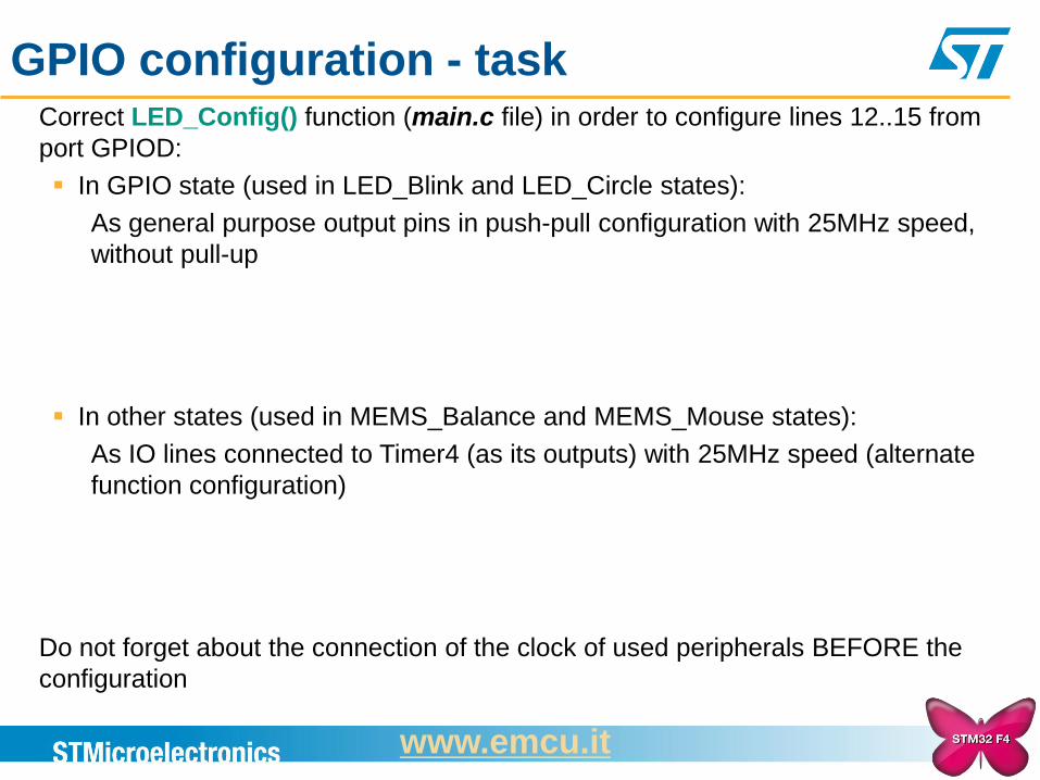
GPIO configuration - task Correct LED_Config() function (main.c file) in order to configure lines 12..15 from
port GPIOD:
In GPIO state (used in LED_Blink and LED_Circle states):
As general purpose output pins in push-pull configuration with 25MHz speed,
without pull-up
In other states (used in MEMS_Balance and MEMS_Mouse states):
As IO lines connected to Timer4 (as its outputs) with 25MHz speed (alternate
function configuration)
Do not forget about the connection of the clock of used peripherals BEFORE the
configuration
www.emcu.it
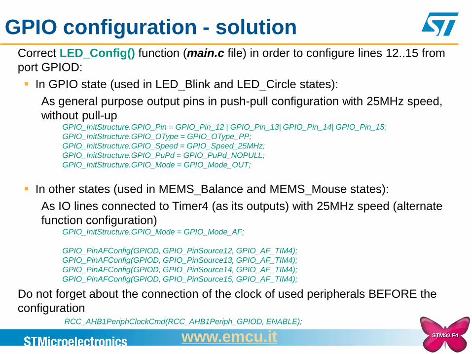
GPIO configuration - solution Correct LED_Config() function (main.c file) in order to configure lines 12..15 from
port GPIOD:
In GPIO state (used in LED_Blink and LED_Circle states):
As general purpose output pins in push-pull configuration with 25MHz speed,
without pull-up GPIO_InitStructure.GPIO_Pin = GPIO_Pin_12 | GPIO_Pin_13| GPIO_Pin_14| GPIO_Pin_15;
GPIO_InitStructure.GPIO_OType = GPIO_OType_PP;
GPIO_InitStructure.GPIO_Speed = GPIO_Speed_25MHz;
GPIO_InitStructure.GPIO_PuPd = GPIO_PuPd_NOPULL;
GPIO_InitStructure.GPIO_Mode = GPIO_Mode_OUT;
In other states (used in MEMS_Balance and MEMS_Mouse states):
As IO lines connected to Timer4 (as its outputs) with 25MHz speed (alternate
function configuration) GPIO_InitStructure.GPIO_Mode = GPIO_Mode_AF;
GPIO_PinAFConfig(GPIOD, GPIO_PinSource12, GPIO_AF_TIM4);
GPIO_PinAFConfig(GPIOD, GPIO_PinSource13, GPIO_AF_TIM4);
GPIO_PinAFConfig(GPIOD, GPIO_PinSource14, GPIO_AF_TIM4);
GPIO_PinAFConfig(GPIOD, GPIO_PinSource15, GPIO_AF_TIM4);
Do not forget about the connection of the clock of used peripherals BEFORE the
configuration RCC_AHB1PeriphClockCmd(RCC_AHB1Periph_GPIOD, ENABLE);
www.emcu.it
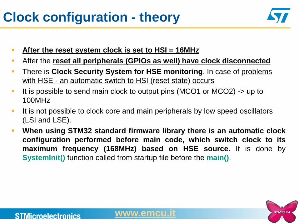
Clock configuration - theory
After the reset system clock is set to HSI = 16MHz
After the reset all peripherals (GPIOs as well) have clock disconnected
There is Clock Security System for HSE monitoring. In case of problems
with HSE - an automatic switch to HSI (reset state) occurs
It is possible to send main clock to output pins (MCO1 or MCO2) -> up to
100MHz
It is not possible to clock core and main peripherals by low speed oscillators
(LSI and LSE).
When using STM32 standard firmware library there is an automatic clock
configuration performed before main code, which switch clock to its
maximum frequency (168MHz) based on HSE source. It is done by
SystemInit() function called from startup file before the main().
www.emcu.it
26
HSI HSE PLLCLK LSE
SYSCLK HSE PLLCLK MCO2 /1..5 PLLI2S
PLL48CLK (USB FS, SDIO & RNG)
CSS
HSE Osc OSC_OUT
OSC_IN
4-26 MHz
PLLCLK
HSI RC
16 MHz
/ M
HSE
HSI SYSCLK
168 MHz max
/ P
/ Q
/ R
x N
PLL
/1..5 MCO1
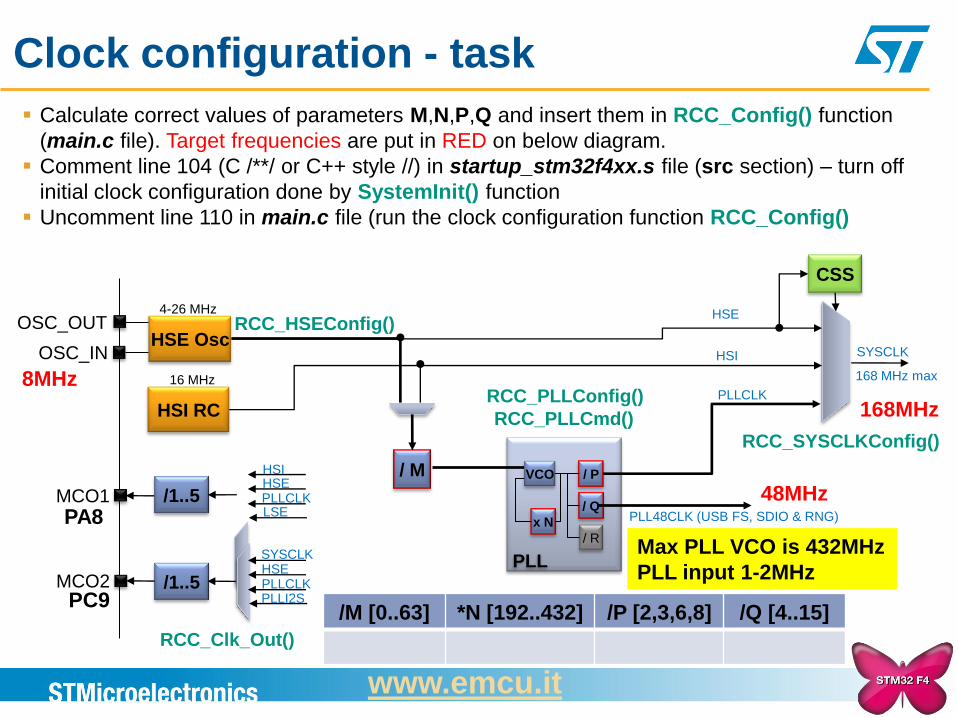
Clock configuration - task
VCO
8MHz
48MHz
168MHz
PA8
PC9
RCC_PLLConfig()
RCC_PLLCmd()
RCC_SYSCLKConfig()
RCC_HSEConfig()
Calculate correct values of parameters M,N,P,Q and insert them in RCC_Config() function
(main.c file). Target frequencies are put in RED on below diagram.
Comment line 104 (C /**/ or C++ style //) in startup_stm32f4xx.s file (src section) – turn off
initial clock configuration done by SystemInit() function
Uncomment line 110 in main.c file (run the clock configuration function RCC_Config()
RCC_Clk_Out()
/M [0..63] *N [192..432] /P [2,3,6,8] /Q [4..15]
Max PLL VCO is 432MHz
PLL input 1-2MHz
www.emcu.it
27
HSI HSE PLLCLK LSE
SYSCLK HSE PLLCLK MCO2 /1..5 PLLI2S
PLL48CLK (USB FS, SDIO & RNG)
CSS
HSE Osc OSC_OUT
OSC_IN
4-26 MHz
PLLCLK
HSI RC
16 MHz
/ M
HSE
HSI SYSCLK
168 MHz max
/ P
/ Q
/ R
x N
PLL
/1..5 MCO1
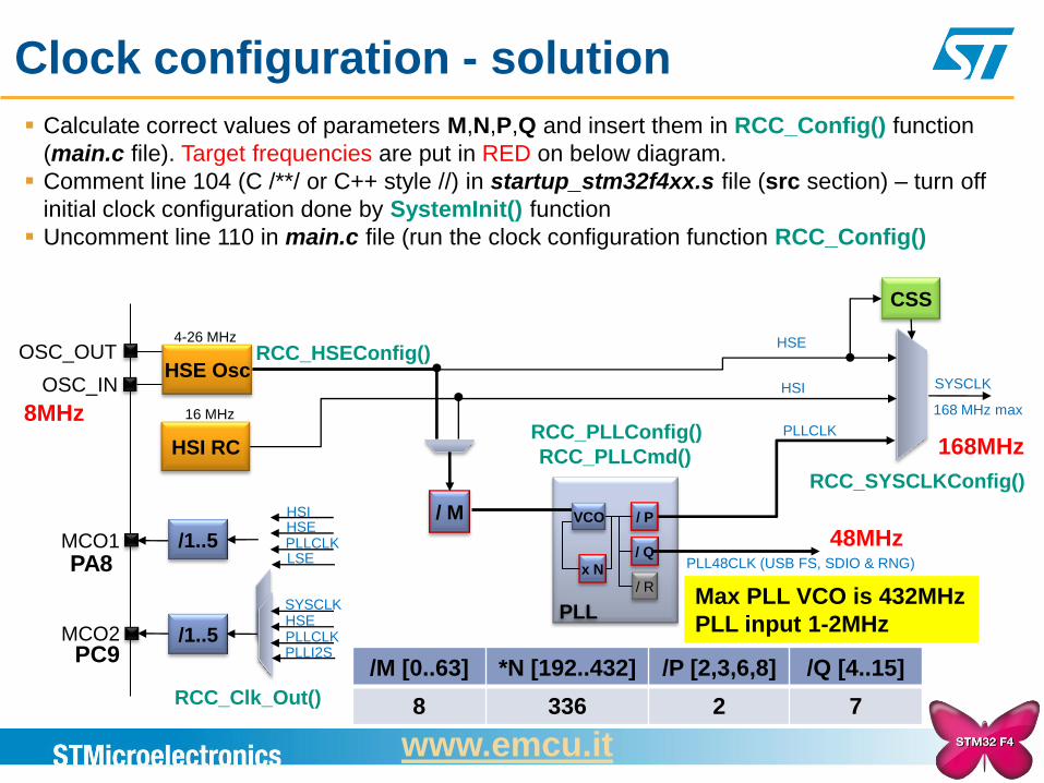
Clock configuration - solution
VCO
8MHz
48MHz
168MHz
PA8
PC9
RCC_PLLConfig()
RCC_PLLCmd()
RCC_SYSCLKConfig()
RCC_HSEConfig()
Calculate correct values of parameters M,N,P,Q and insert them in RCC_Config() function
(main.c file). Target frequencies are put in RED on below diagram.
Comment line 104 (C /**/ or C++ style //) in startup_stm32f4xx.s file (src section) – turn off
initial clock configuration done by SystemInit() function
Uncomment line 110 in main.c file (run the clock configuration function RCC_Config()
RCC_Clk_Out()
/M [0..63] *N [192..432] /P [2,3,6,8] /Q [4..15]
8 336 2 7
Max PLL VCO is 432MHz
PLL input 1-2MHz
www.emcu.it
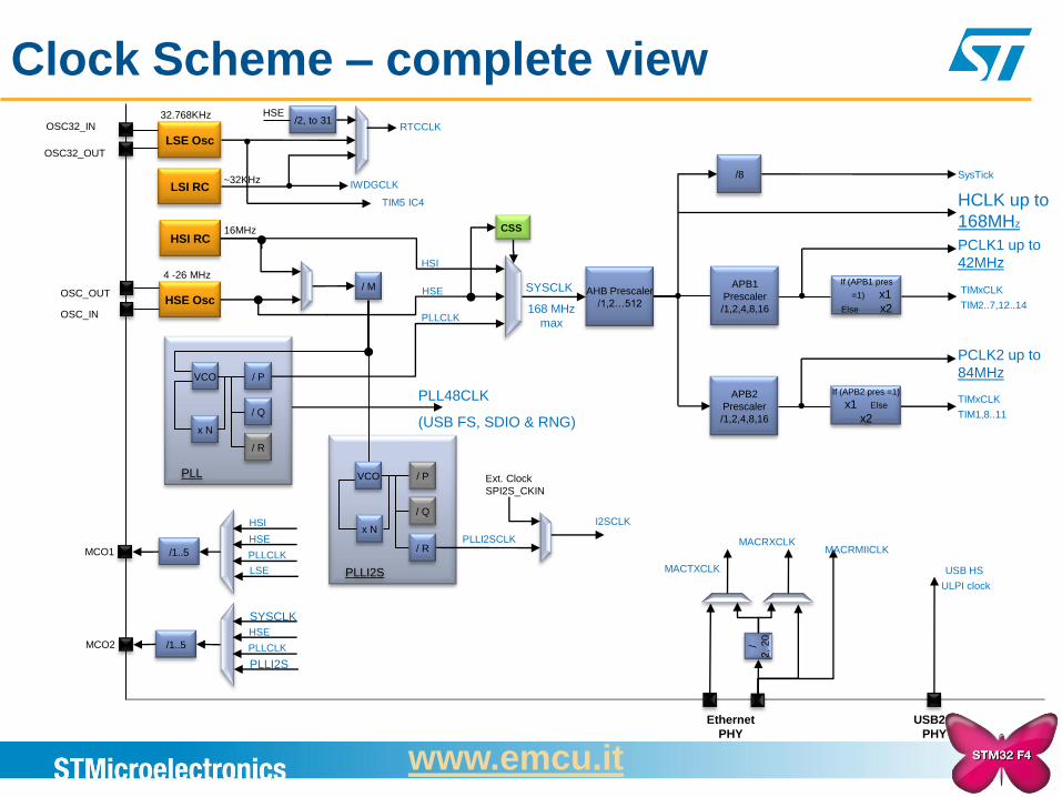
Clock Scheme – complete view
28
HSI
HSE
PLLCLK MCO1 /1..5
LSE
SYSCLK
HSE
PLLCLK MCO2 /1..5
PLLI2S
LSI RC
32.768KHz /2, to 31
LSE Osc
OSC32_IN
OSC32_OUT
~32KHz IWDGCLK
RTCCLK
TIM5 IC4
HSE
/
2,
20
MACTXCLK
MACRXCLK MACRMIICLK
USB HS
ULPI clock
/ P
/ Q
/ R
x N
PLLI2S
I2SCLK
Ext. Clock
SPI2S_CKIN
PLLI2SCLK
VCO
PCLK1 up to
42MHz
If (APB2 pres =1)
x1 Else
x2
If (APB1 pres
=1) x1
Else x2
PCLK2 up to
84MHz
TIMxCLK
TIM2..7,12..14
APB1
Prescaler
/1,2,4,8,16
TIMxCLK
TIM1,8..11
APB2
Prescaler
/1,2,4,8,16
HCLK up to
168MHz
AHB Prescaler
/1,2…512
/8 SysTick
PLL48CLK
(USB FS, SDIO & RNG)
CSS
HSE Osc OSC_OUT
OSC_IN
4 -26 MHz
PLLCLK
HSI RC 16MHz
/ M HSE
HSI
SYSCLK
168 MHz
max
/ P
/ Q
/ R
VCO
x N
PLL
Ethernet
PHY
USB2.0
PHY
www.emcu.it
Interrupts - theory
After the reset all peripheral interrupts are disabled, vector table is located
at the beginning of the Flash memory
Interrupt should be:
enabled at peripheral -> exact source of the interrupt
configured in NVIC (interrupt controller) -> priorities, location in memory
programmed in stm32f4xx_it.c -> body of its procedure
In addition external interrupt requires:
Configuration of dedicated IO pin as input (GPIO module)
Specify if it will be event or interrupt mode (EXTI module)
Select proper port to source interrupt at the selected channel (i.e
Channel 1 can be sourced by Pin 1 from any port (SYSCFG module)
Enable external interrupt channel (EXTI module)
Select sensitivity of the channel (raising or falling edge) (EXTI module)
www.emcu.it
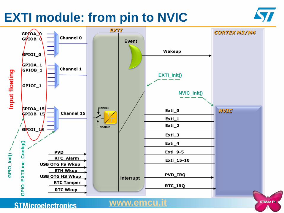
EXTI module: from pin to NVIC GPIOA_0
GPIOB_0
GPIOI_0
EXTI
Channel 0
GPIOA_1
GPIOB_1
GPIOI_1
Channel 1
GPIOA_15
GPIOB_15
GPIOI_15
Channel 15
CORTEX M3/M4
NVIC Exti_0
Exti_1
Exti_2
Exti_3
Exti_4
Exti_9-5
Exti_15-10
Wakeup
RTC Tamper
RTC Wkup
Event
Interrupt
ENABLE
DISABLE
Inp
ut
flo
ati
ng
PVD_IRQ
RTC_IRQ
GP
IO_
EX
TIL
ine
_C
on
fig
()
GP
IO_
Init
()
EXTI_Init()
NVIC_Init()
USB OTG HS Wkup
ETH Wkup
USB OTG FS Wkup
RTC_Alarm
PVD
www.emcu.it
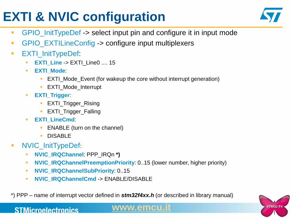
EXTI & NVIC configuration GPIO_InitTypeDef -> select input pin and configure it in input mode
GPIO_EXTILineConfig -> configure input multiplexers
EXTI_InitTypeDef: EXTI_Line -> EXTI_Line0 .... 15
EXTI_Mode:
EXTI_Mode_Event (for wakeup the core without interrupt generation)
EXTI_Mode_Interrupt
EXTI_Trigger:
EXTI_Trigger_Rising
EXTI_Trigger_Falling
EXTI_LineCmd:
ENABLE (turn on the channel)
DISABLE
NVIC_InitTypeDef: NVIC_IRQChannel: PPP_IRQn *)
NVIC_IRQChannelPreemptionPriority: 0..15 (lower number, higher priority)
NVIC_IRQChannelSubPriority: 0..15
NVIC_IRQChannelCmd -> ENABLE/DISABLE
*) PPP – name of interrupt vector defined in stm32f4xx.h (or described in library manual)
www.emcu.it
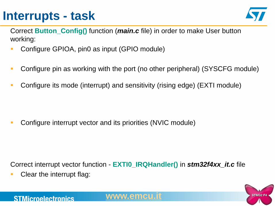
Interrupts - task Correct Button_Config() function (main.c file) in order to make User button
working:
Configure GPIOA, pin0 as input (GPIO module)
Configure pin as working with the port (no other peripheral) (SYSCFG module)
Configure its mode (interrupt) and sensitivity (rising edge) (EXTI module)
Configure interrupt vector and its priorities (NVIC module)
Correct interrupt vector function - EXTI0_IRQHandler() in stm32f4xx_it.c file
Clear the interrupt flag:
www.emcu.it
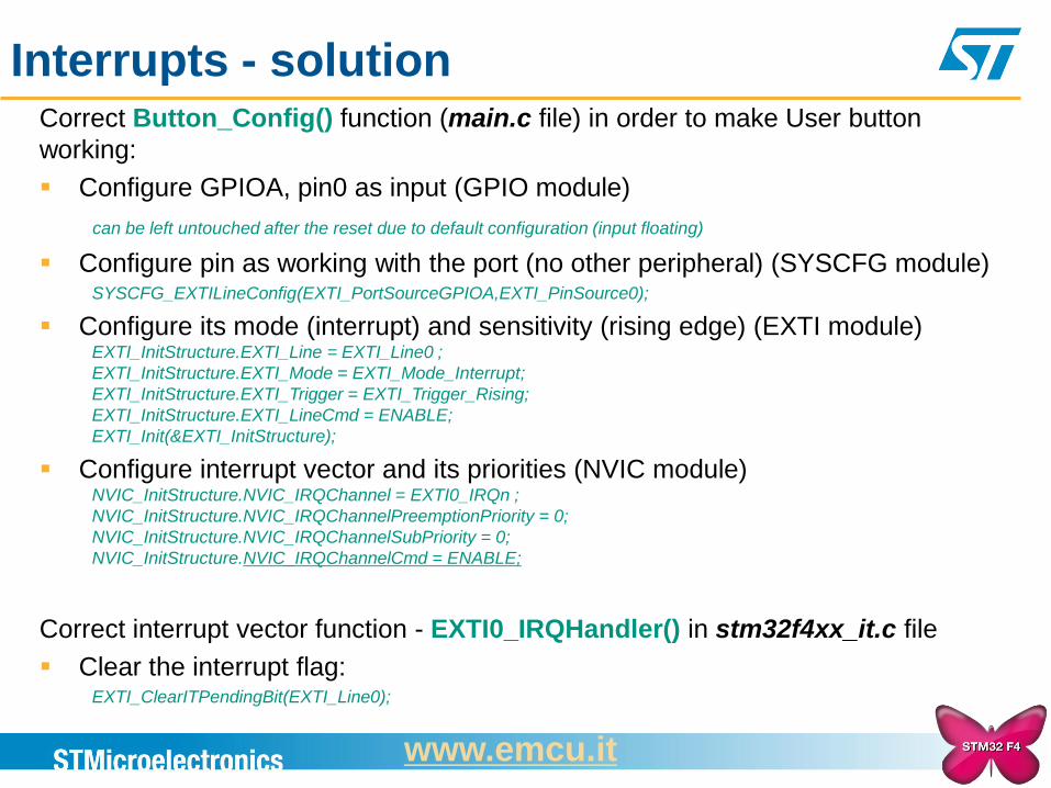
Interrupts - solution Correct Button_Config() function (main.c file) in order to make User button
working:
Configure GPIOA, pin0 as input (GPIO module)
can be left untouched after the reset due to default configuration (input floating)
Configure pin as working with the port (no other peripheral) (SYSCFG module) SYSCFG_EXTILineConfig(EXTI_PortSourceGPIOA,EXTI_PinSource0);
Configure its mode (interrupt) and sensitivity (rising edge) (EXTI module) EXTI_InitStructure.EXTI_Line = EXTI_Line0 ;
EXTI_InitStructure.EXTI_Mode = EXTI_Mode_Interrupt;
EXTI_InitStructure.EXTI_Trigger = EXTI_Trigger_Rising;
EXTI_InitStructure.EXTI_LineCmd = ENABLE;
EXTI_Init(&EXTI_InitStructure);
Configure interrupt vector and its priorities (NVIC module) NVIC_InitStructure.NVIC_IRQChannel = EXTI0_IRQn ;
NVIC_InitStructure.NVIC_IRQChannelPreemptionPriority = 0;
NVIC_InitStructure.NVIC_IRQChannelSubPriority = 0;
NVIC_InitStructure.NVIC_IRQChannelCmd = ENABLE;
Correct interrupt vector function - EXTI0_IRQHandler() in stm32f4xx_it.c file
Clear the interrupt flag: EXTI_ClearITPendingBit(EXTI_Line0);
www.emcu.it
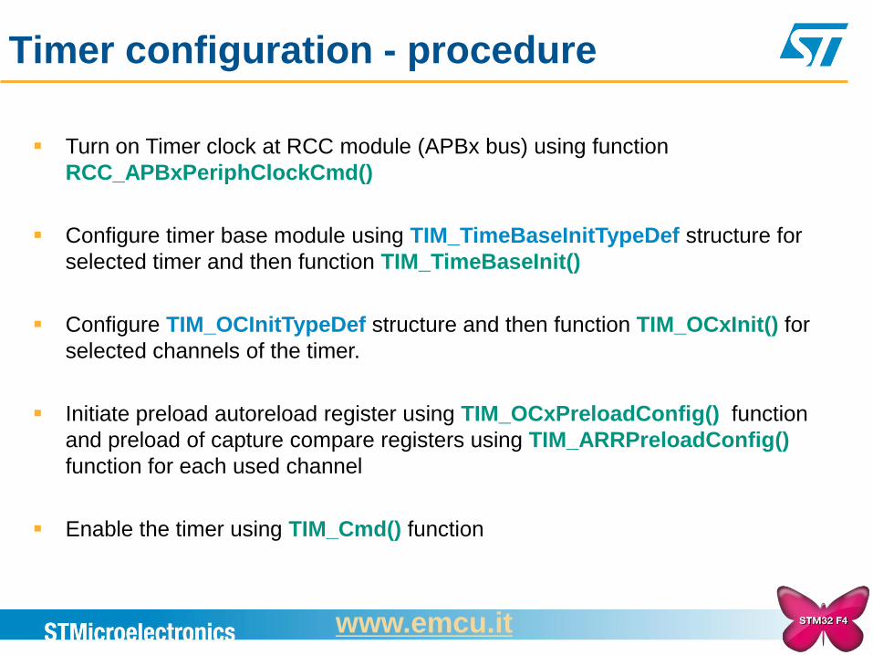
Timer configuration - procedure
Turn on Timer clock at RCC module (APBx bus) using function
RCC_APBxPeriphClockCmd()
Configure timer base module using TIM_TimeBaseInitTypeDef structure for
selected timer and then function TIM_TimeBaseInit()
Configure TIM_OCInitTypeDef structure and then function TIM_OCxInit() for
selected channels of the timer.
Initiate preload autoreload register using TIM_OCxPreloadConfig() function
and preload of capture compare registers using TIM_ARRPreloadConfig()
function for each used channel
Enable the timer using TIM_Cmd() function
www.emcu.it
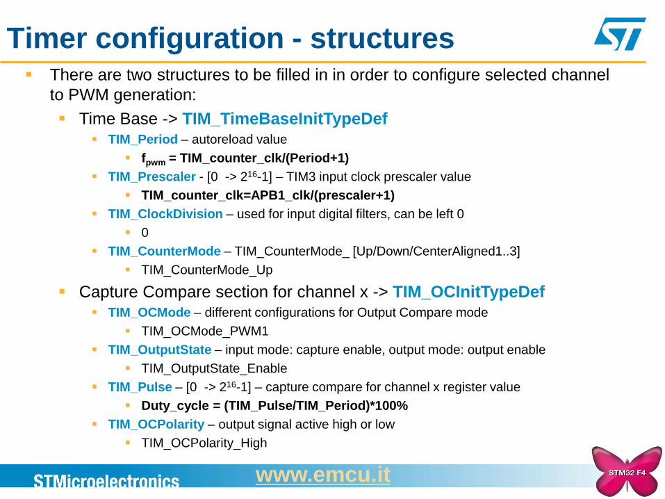
Timer configuration - structures There are two structures to be filled in in order to configure selected channel
to PWM generation:
Time Base -> TIM_TimeBaseInitTypeDef TIM_Period – autoreload value
fpwm = TIM_counter_clk/(Period+1)
TIM_Prescaler - [0 -> 216-1] – TIM3 input clock prescaler value
TIM_counter_clk=APB1_clk/(prescaler+1)
TIM_ClockDivision – used for input digital filters, can be left 0
0
TIM_CounterMode – TIM_CounterMode_ [Up/Down/CenterAligned1..3]
TIM_CounterMode_Up
Capture Compare section for channel x -> TIM_OCInitTypeDef TIM_OCMode – different configurations for Output Compare mode
TIM_OCMode_PWM1
TIM_OutputState – input mode: capture enable, output mode: output enable
TIM_OutputState_Enable
TIM_Pulse – [0 -> 216-1] – capture compare for channel x register value
Duty_cycle = (TIM_Pulse/TIM_Period)*100%
TIM_OCPolarity – output signal active high or low
TIM_OCPolarity_High
www.emcu.it
Timer3 – Output Compare mode - task
16-Bit Prescaler
ITR 1..4
Trigger/Clock
Controller
Trigger Output
APB1 clk
Auto Reload REG
+/- 16-Bit Counter
CH1
CH2
CH3
CH4
ETR
Capture Compare
Capture Compare
Capture Compare
Capture Compare
CH1
CH2
CH3
CH4
TIM_Period
TIM_Pulse
TIM_Prescaler
TIM_CounterMode
TIM_OCMode
TIM_OutputState
TIM_OCPolarity
TIM_ClockDivision
TIM_TimeBaseInit()
TIM_TimeBaseInitTypeDef
TIM_OCxInit()
TIM_OCInitTypeDef
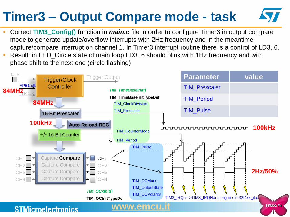
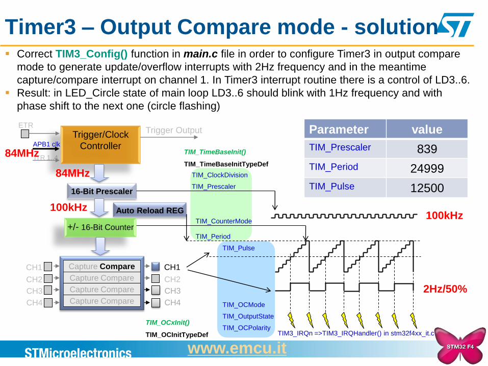
Correct TIM3_Config() function in main.c file in order to configure Timer3 in output compare
mode to generate update/overflow interrupts with 2Hz frequency and in the meantime
capture/compare interrupt on channel 1. In Timer3 interrupt routine there is a control of LD3..6.
Result: in LED_Circle state of main loop LD3..6 should blink with 1Hz frequency and with
phase shift to the next one (circle flashing)
84MHz
84MHz
100kHz
2Hz/50%
100kHz
Parameter value
TIM_Prescaler
TIM_Period
TIM_Pulse
TIM3_IRQn =>TIM3_IRQHandler() in stm32f4xx_it.c
www.emcu.it
Timer3 – Output Compare mode - solution
16-Bit Prescaler
ITR 1..4
Trigger/Clock
Controller
Trigger Output
APB1 clk
Auto Reload REG
+/- 16-Bit Counter
CH1
CH2
CH3
CH4
ETR
Capture Compare
Capture Compare
Capture Compare
Capture Compare
CH1
CH2
CH3
CH4
TIM_Period
TIM_Pulse
TIM_Prescaler
TIM_CounterMode
TIM_OCMode
TIM_OutputState
TIM_OCPolarity
TIM_ClockDivision
TIM_TimeBaseInit()
TIM_TimeBaseInitTypeDef
TIM_OCxInit()
TIM_OCInitTypeDef
84MHz
84MHz
100kHz
2Hz/50%
100kHz
Parameter value
TIM_Prescaler 839
TIM_Period 24999
TIM_Pulse 12500
TIM3_IRQn =>TIM3_IRQHandler() in stm32f4xx_it.c
Correct TIM3_Config() function in main.c file in order to configure Timer3 in output compare
mode to generate update/overflow interrupts with 2Hz frequency and in the meantime
capture/compare interrupt on channel 1. In Timer3 interrupt routine there is a control of LD3..6.
Result: in LED_Circle state of main loop LD3..6 should blink with 1Hz frequency and with
phase shift to the next one (circle flashing)
www.emcu.it
FPU configuration in STM32
TrueStudio
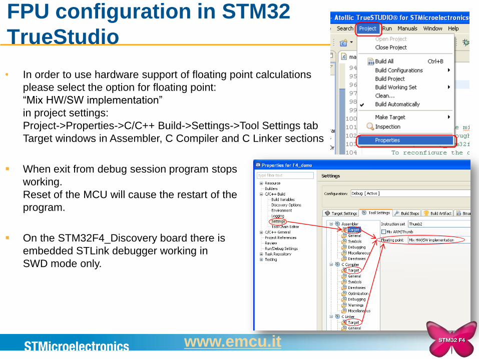
• In order to use hardware support of floating point calculations
please select the option for floating point:
“Mix HW/SW implementation”
in project settings:
Project->Properties->C/C++ Build->Settings->Tool Settings tab
Target windows in Assembler, C Compiler and C Linker sections
When exit from debug session program stops
working.
Reset of the MCU will cause the restart of the
program.
On the STM32F4_Discovery board there is
embedded STLink debugger working in
SWD mode only.
www.emcu.it
FPU - task
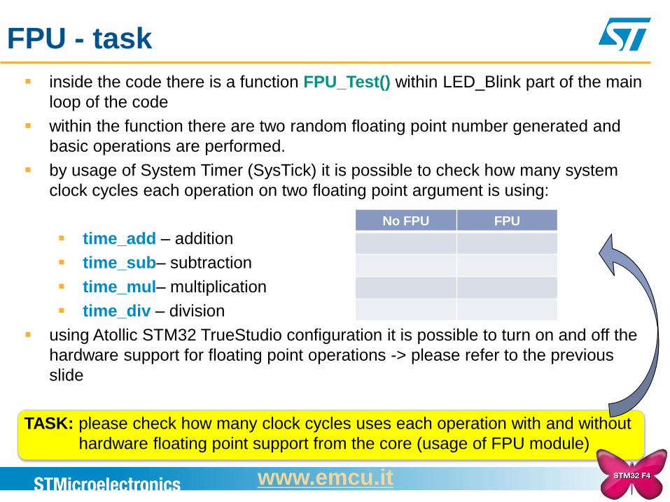
inside the code there is a function FPU_Test() within LED_Blink part of the main
loop of the code
within the function there are two random floating point number generated and
basic operations are performed.
by usage of System Timer (SysTick) it is possible to check how many system
clock cycles each operation on two floating point argument is using:
time_add – addition
time_sub– subtraction
time_mul– multiplication
time_div – division
using Atollic STM32 TrueStudio configuration it is possible to turn on and off the
hardware support for floating point operations -> please refer to the previous
slide
TASK: please check how many clock cycles uses each operation with and without
hardware floating point support from the core (usage of FPU module)
No FPU FPU
www.emcu.it
FPU - solution
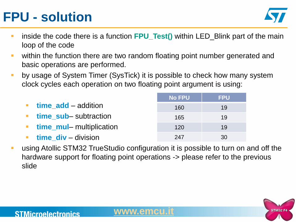
inside the code there is a function FPU_Test() within LED_Blink part of the main
loop of the code
within the function there are two random floating point number generated and
basic operations are performed.
by usage of System Timer (SysTick) it is possible to check how many system
clock cycles each operation on two floating point argument is using:
time_add – addition
time_sub– subtraction
time_mul– multiplication
time_div – division
using Atollic STM32 TrueStudio configuration it is possible to turn on and off the
hardware support for floating point operations -> please refer to the previous
slide
No FPU FPU
160 19
165 19
120 19
247 30
www.emcu.it
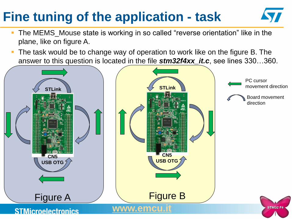
Fine tuning of the application - task The MEMS_Mouse state is working in so called “reverse orientation” like in the
plane, like on figure A.
The task would be to change way of operation to work like on the figure B. The
answer to this question is located in the file stm32f4xx_it.c, see lines 330…360.
Figure A
CN5
USB OTG
STLink
Figure B
CN5
USB OTG
STLink
PC cursor
movement direction
Board movement
direction
www.emcu.it
More info
STM32F4xx are here
STM32 motor control is here
STM32W is here
SPEAr is here
ST-Link-v2 is here
M24LRxx memory + RFID is here
Power Line Module is here
MEMS is here
ATOLLIC tips and tricks are here
In general information concerning STM32xx, STM8xx, MEMS, RFID, SMART Meter, ZigBee, Blue Tooth, etc are here
www.emcu.it
Recommended