STEERINGS Y S T E MReturn To Main Table of ContentsGENERAL . . . . . . . . . . . . . . . . . . . . . . . . . . . . . . . . . . . . . . . . . . . . . . 2
STEERING COLUMN AND SHAFT . . . . . . . . . . . . . . . . . . . . 13
POWER STEERING GEAR BOX (TRW) . . . . . . . . . . . . . . . . 18
POWER STEERING GEAR BOX (MANDO) . . . . . . . . . . . . 2 4
POWER STEERING OIL PUMP . . . . . . . . . . . . . . . . . . . . . . . . 3 7
POWER STEERING HOSES . . . . . . . . . . . . . . . . . . . . . . . . . . . 4 3
GENERAL
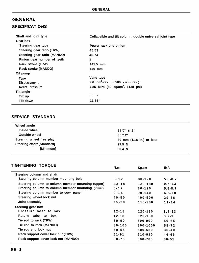
Shaft and joint typeGear box
Steering gear type
Steering gear ratio (TRW)
Steering gear ratio (MANDO)Pinion gear number of teeth
Rack stroke (TRW)Rack stroke (MANDO)
Oil pump
TypeDisplacementRelief pressure
Tilt angleTilt upTilt down
Collapsible and tilt column, double universal joint type
Power rack and pinion
45.5345.74
8141.5 mm
140 mm
Vane type9.6 cm3/rev. (0.586 cu.in./rev.)7.85 MPa (80 kg/cm2, 1138 psi)
3.85°11.55°
SERVICE STANDARD
Wheel angleInside wheelOutside wheel
Steering wheel free playSteering effort [Standard]
[Minimum]
37°7’ ± 2°30°12’30 mm (1.18 in.) or less27.5 N
30.4 N
TIGHTENING TORQUEN.m Kg.cm Ib.ft
Steering column and shaftSteering column member mounting bolt
Steering column to column member mounting (upper)Steering column to column member mounting (lower)Steering column member to cowl panel
Steering wheel lock nutJoint assembly
Steering gear boxPressure hose to boxReturn tube to box
Tie rod to rack (TRW)
Tie rod to rack (MANDO)Tie rod end lock nutRack support cover lock nut (TRW)
Rack support cover lock nut (MANDO)
8 - 1 2 8 0 - 1 2 0 5.8-8 .7
1 3 - 1 8 1 3 0 - 1 8 0 9 . 4 - 1 38 - 1 2 8 0 - 1 2 0 5.8-8 .79 - 1 4 9 0 - 1 4 0 6 . 5 - 1 04 0 - 5 0 4 0 0 - 5 0 0 2 9 - 3 61 5 - 2 0 1 5 0 - 2 0 0 1 1 - 1 4
1 2 - 1 8 1 2 0 - 1 8 0 8 . 7 - 1 31 2 - 1 8 1 2 0 - 1 8 0 8 . 7 - 1 36 9 - 9 0 6 9 0 - 9 0 0 5 0 - 6 58 0 - 1 0 0 8 0 0 - 1 0 0 0 5 8 - 7 25 0 - 5 5 5 0 0 - 5 5 0 3 6 - 4 06 1 - 9 1 6 1 0 - 9 1 0 4 4 - 6 65 0 - 7 0 5 0 0 - 7 0 0 3 6 - 5 1
5 6 - 2
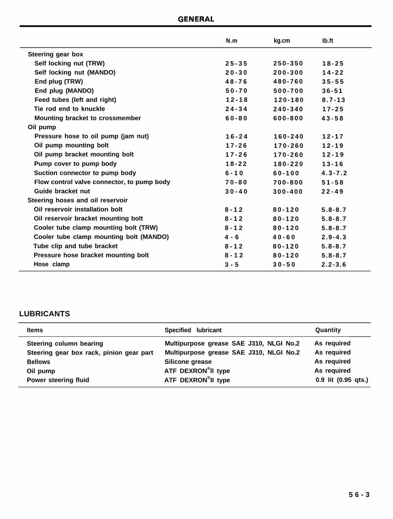
N.m kg.cm Ib.ft
Steering gear boxSelf locking nut (TRW)Self locking nut (MANDO)End plug (TRW)
End plug (MANDO)Feed tubes (left and right)Tie rod end to knuckle
Mounting bracket to crossmemberOil pump
Pressure hose to oil pump (jam nut)Oil pump mounting boltOil pump bracket mounting bolt
Pump cover to pump body
Suction connector to pump bodyFlow control valve connector, to pump body
Guide bracket nutSteering hoses and oil reservoir
Oil reservoir installation boltOil reservoir bracket mounting bolt
Cooler tube clamp mounting bolt (TRW)
Cooler tube clamp mounting bolt (MANDO)
Tube clip and tube bracketPressure hose bracket mounting boltHose clamp
2 5 - 3 5 2 5 0 - 3 5 0 1 8 - 2 52 0 - 3 0 2 0 0 - 3 0 0 1 4 - 2 24 8 - 7 6 4 8 0 - 7 6 0 3 5 - 5 55 0 - 7 0 5 0 0 - 7 0 0 3 6 - 5 11 2 - 1 8 1 2 0 - 1 8 0 8 . 7 - 1 32 4 - 3 4 2 4 0 - 3 4 0 1 7 - 2 56 0 - 8 0 6 0 0 - 8 0 0 4 3 - 5 8
1 6 - 2 4 1 6 0 - 2 4 0 1 2 - 1 71 7 - 2 6 1 7 0 - 2 6 0 1 2 - 1 91 7 - 2 6 1 7 0 - 2 6 0 1 2 - 1 9
1 8 - 2 2 1 8 0 - 2 2 0 1 3 - 1 66 - 1 0 6 0 - 1 0 0 4 . 3 - 7 . 2
7 0 - 8 0 7 0 0 - 8 0 0 5 1 - 5 83 0 - 4 0 3 0 0 - 4 0 0 2 2 - 4 9
8 - 1 2 8 0 - 1 2 0 5.8-8 .78 - 1 2 8 0 - 1 2 0 5.8-8 .78 - 1 2 8 0 - 1 2 0 5.8-8 .74 - 6 4 0 - 6 0 2.9-4 .3
8 - 1 2 8 0 - 1 2 0 5.8-8 .78 - 1 2 8 0 - 1 2 0 5.8-8 .7
3 - 5 3 0 - 5 0 2.2-3 .6
LUBRICANTS
Items Specified lubricant Quantity
Steering column bearing Multipurpose grease SAE J310, NLGI No.2 As required
Steering gear box rack, pinion gear part Multipurpose grease SAE J310, NLGI No.2 As required
Bellows Silicone grease As required
Oil pump ATF DEXRON®ll type As required
Power steering fluid ATF DEXRON®II type 0.9 lit (0.95 qts.)
5 6 - 3
GENERAL
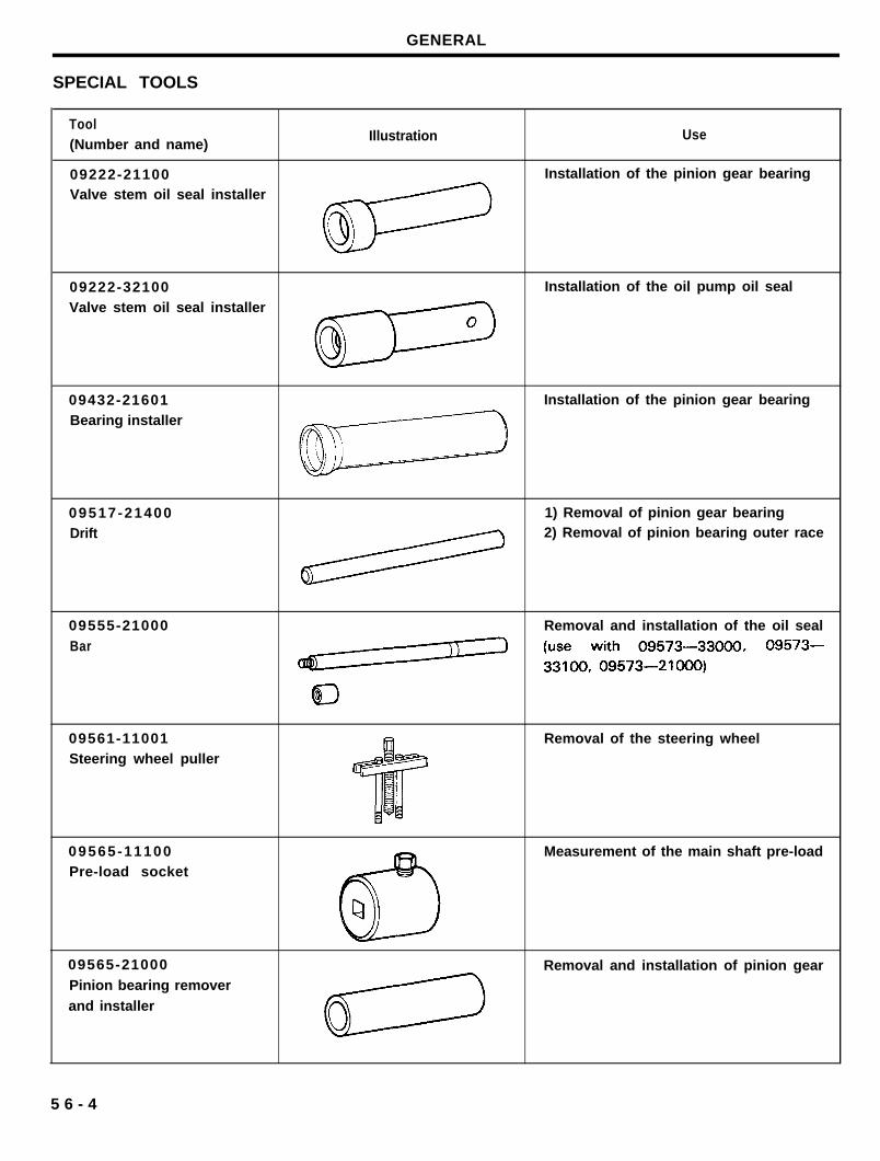
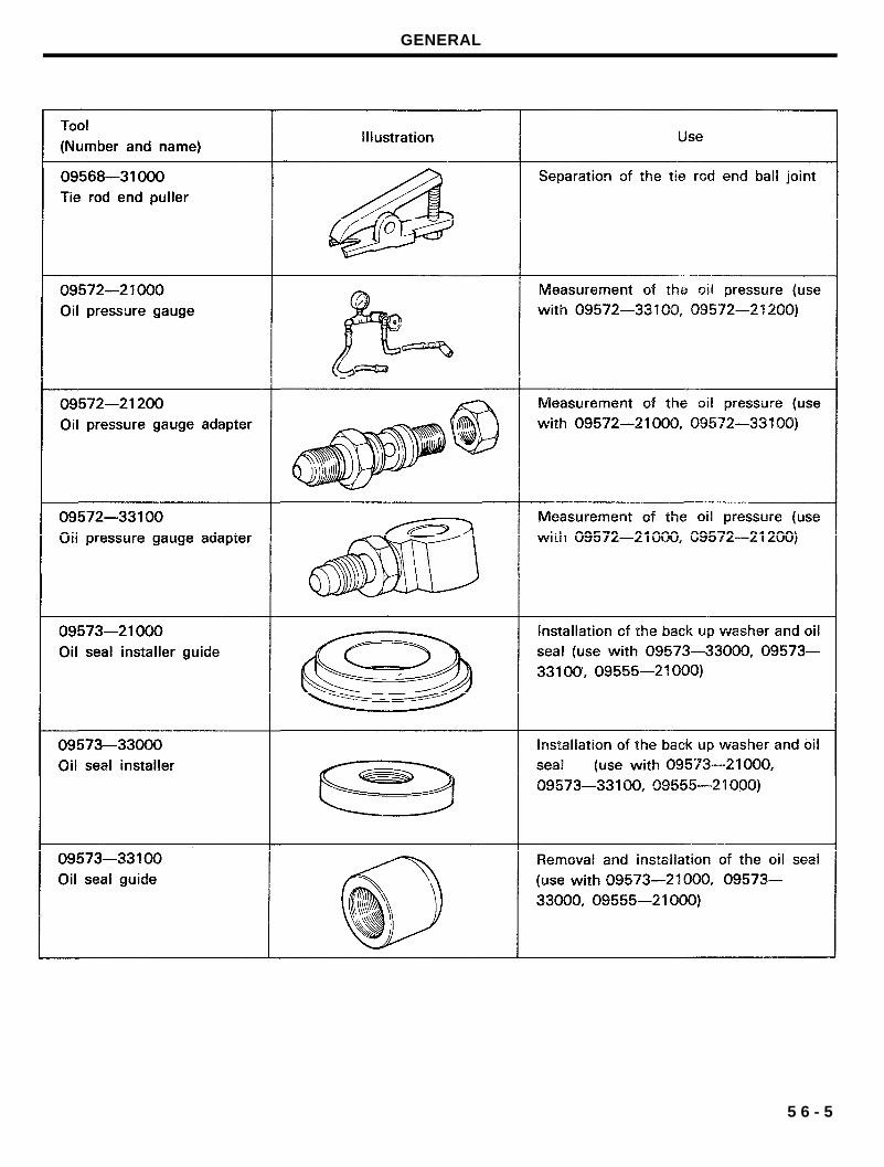
SPECIAL TOOLS
Tool(Number and name)
Illustration Use
09222-21100 Installation of the pinion gear bearing
Valve stem oil seal installer
09222-32100 Installation of the oil pump oil seal
Valve stem oil seal installer
09432-21601 Installation of the pinion gear bearing
Bearing installer
09517-21400 1) Removal of pinion gear bearing
Drift 2) Removal of pinion bearing outer race
09555-21000
Bar
09561-11001Steering wheel puller
Removal and installation of the oil seal
Removal of the steering wheel
09565-11100Pre-load socket
Measurement of the main shaft pre-load
09565-21000
Pinion bearing remover
and installer
Removal and installation of pinion gear
5 6 - 4
GENERAL
5 6 - 5
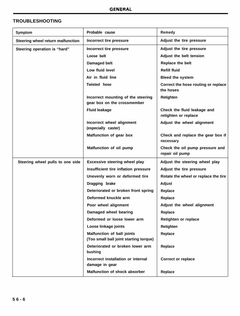
TROUBLESHOOTING
Symptom Probable cause Remedy
Steering wheel return malfunction Incorrect tire pressure Adjust the tire pressure
Steering operation is “hard” Incorrect tire pressure Adjust the tire pressure
Loose belt Adjust the belt tension
Damaged belt Replace the belt
Low fluid level Refill fluid
Air in fluid line Bleed the system
Twisted hose Correct the hose routing or replacethe hoses
Incorrect mounting of the steeringgear box on the crossmember
Fluid leakage
Retighten
Check the fluid leakage andretighten or replace
Incorrect wheel alignment(especially caster)
Malfunction of gear box
Adjust the wheel alignment
Check and replace the gear box if
necessary
Malfunction of oil pump Check the oil pump pressure and
repair oil pump
Steering wheel pulls to one side Excessive steering wheel play Adjust the steering wheel play
Insufficient tire inflation pressure Adjust the tire pressure
Unevenly worn or deformed tire Rotate the wheel or replace the tire
Dragging brake Adjust
Deteriorated or broken front spring Replace
Deformed knuckle arm Replace
Poor wheel alignment Adjust the wheel alignment
Damaged wheel bearing Replace
Deformed or loose lower arm Retighten or replace
Loose linkage joints Retighten
Malfunction of ball joints Replace(Too small ball joint starting torque)
Deteriorated or broken lower arm Replacebushing
Incorrect installation or internal
damage in gear
Malfunction of shock absorber
Correct or replace
Replace
5 6 - 6
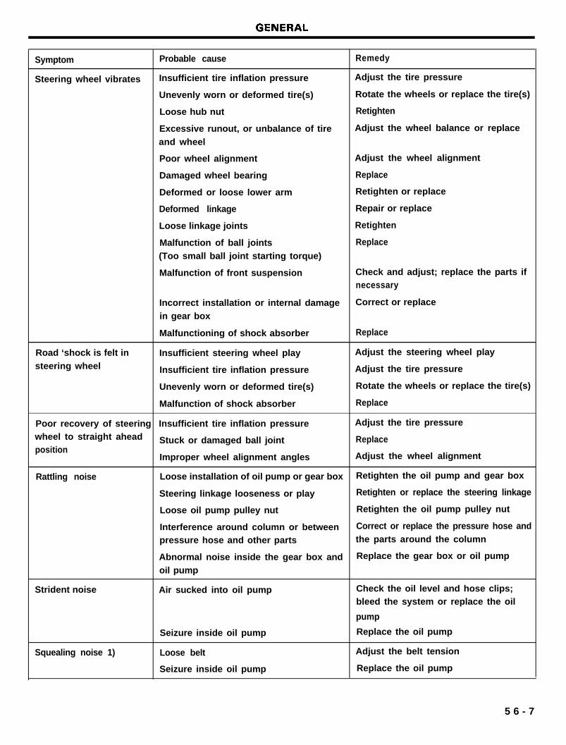
Symptom
Steering wheel vibrates
Probable cause
Insufficient tire inflation pressure
Unevenly worn or deformed tire(s)
Loose hub nut
Excessive runout, or unbalance of tire
and wheel
Poor wheel alignment
Damaged wheel bearing
Deformed or loose lower arm
Deformed linkage
Loose linkage joints
Malfunction of ball joints
(Too small ball joint starting torque)
Malfunction of front suspension
Remedy
Adjust the tire pressure
Rotate the wheels or replace the tire(s)
Retighten
Adjust the wheel balance or replace
Adjust the wheel alignment
Replace
Retighten or replace
Repair or replace
Retighten
Replace
Check and adjust; replace the parts ifnecessary
Incorrect installation or internal damage Correct or replace
in gear box
Malfunctioning of shock absorber Replace
Road ‘shock is felt in Insufficient steering wheel play Adjust the steering wheel play
steering wheel Insufficient tire inflation pressure Adjust the tire pressure
Unevenly worn or deformed tire(s) Rotate the wheels or replace the tire(s)
Malfunction of shock absorber Replace
Poor recovery of steering Insufficient tire inflation pressure Adjust the tire pressure
wheel to straight ahead Stuck or damaged ball joint Replaceposition
Improper wheel alignment angles Adjust the wheel alignment
Rattling noise Loose installation of oil pump or gear box Retighten the oil pump and gear box
Steering linkage looseness or play Retighten or replace the steering linkage
Loose oil pump pulley nut Retighten the oil pump pulley nut
Interference around column or between Correct or replace the pressure hose and
pressure hose and other parts the parts around the column
Abnormal noise inside the gear box and Replace the gear box or oil pump
oil pump
Strident noise Air sucked into oil pump Check the oil level and hose clips;bleed the system or replace the oil
pump
Seizure inside oil pump Replace the oil pump
Squealing noise 1) Loose belt Adjust the belt tension
Seizure inside oil pump Replace the oil pump
5 6 - 7
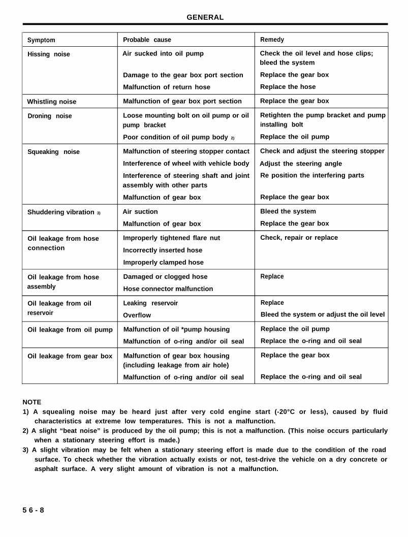
GENERAL
Symptom Probable cause Remedy
Hissing noise Air sucked into oil pump Check the oil level and hose clips;bleed the system
Damage to the gear box port section Replace the gear box
Malfunction of return hose Replace the hose
Whistling noise Malfunction of gear box port section Replace the gear box
Droning noise Loose mounting bolt on oil pump or oil Retighten the pump bracket and pump
pump bracket installing bolt
Poor condition of oil pump body 2) Replace the oil pump
Squeaking noise Malfunction of steering stopper contact Check and adjust the steering stopper
Interference of wheel with vehicle body Adjust the steering angle
Interference of steering shaft and joint Re position the interfering parts
assembly with other parts
Malfunction of gear box Replace the gear box
Shuddering vibration 3) Air suction Bleed the system
Malfunction of gear box Replace the gear box
Oil leakage from hose Improperly tightened flare nut Check, repair or replace
connection Incorrectly inserted hose
Improperly clamped hose
Oil leakage from hose Damaged or clogged hose Replace
assembly Hose connector malfunction
Oil leakage from oil Leaking reservoir Replace
reservoir Overflow Bleed the system or adjust the oil level
Oil leakage from oil pump Malfunction of oil *pump housing Replace the oil pump
Malfunction of o-ring and/or oil seal Replace the o-ring and oil seal
Oil leakage from gear box Malfunction of gear box housing Replace the gear box
(including leakage from air hole)
Malfunction of o-ring and/or oil seal Replace the o-ring and oil seal
NOTE
1) A squealing noise may be heard just after very cold engine start (-20°C or less), caused by fluidcharacteristics at extreme low temperatures. This is not a malfunction.
2) A slight “beat noise” is produced by the oil pump; this is not a malfunction. (This noise occurs particularlywhen a stationary steering effort is made.)
3) A slight vibration may be felt when a stationary steering effort is made due to the condition of the road
surface. To check whether the vibration actually exists or not, test-drive the vehicle on a dry concrete orasphalt surface. A very slight amount of vibration is not a malfunction.
5 6 - 8
SERVICE ADJUSTMENT PROCEDURE
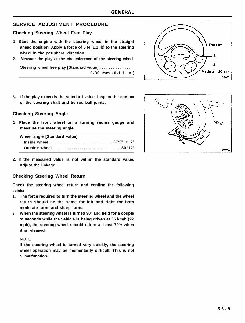
Checking Steering Wheel Free Play
1. Start the engine with the steering wheel in the straightahead position. Apply a force of 5 N (1.1 lb) to the steering
wheel in the peripheral direction.
2. Measure the play at the circumference of the steering wheel.
Steering wheel free play [Standard value] . . . . . . . . . . . . . . .0-30 mm (0-1.1 in.)
3. If the play exceeds the standard value, inspect the contactof the steering shaft and tie rod ball joints.
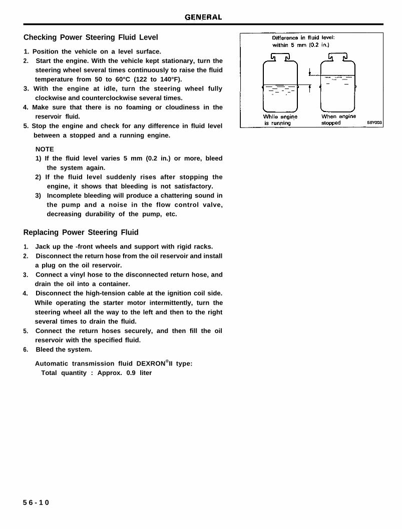
Checking Steering Angle
1. Place the front wheel on a turning radius gauge and
measure the steering angle.
Wheel angle [Standard value]
Inside wheel . . . . . . . . . . . . . . . . . . . . . . . . . . . . . . . 37°7’ ± 2°
Outside wheel . . . . . . . . . . . . . . . . . . . . . . . . . . . . . . . . . 30°12’
2. If the measured value is not within the standard value.Adjust the linkage.
Checking Steering Wheel Return
Check the steering wheel return and confirm the followingpoints:1. The force required to turn the steering wheel and the wheel
return should be the same for left and right for bothmoderate turns and sharp turns.
2. When the steering wheel is turned 90° and held for a couple
of seconds while the vehicle is being driven at 35 km/h (22mph), the steering wheel should return at least 70% whenit is released.
NOTEIf the steering wheel is turned very quickly, the steering
wheel operation may be momentarily difficult. This is nota malfunction.
5 6 - 9
Checking Power Steering Fluid Level
1. Position the vehicle on a level surface.2. Start the engine. With the vehicle kept stationary, turn the
steering wheel several times continuously to raise the fluidtemperature from 50 to 60°C (122 to 140°F).
3. With the engine at idle, turn the steering wheel fully
clockwise and counterclockwise several times.4. Make sure that there is no foaming or cloudiness in the
reservoir fluid.
5. Stop the engine and check for any difference in fluid level
between a stopped and a running engine.
NOTE1) If the fluid level varies 5 mm (0.2 in.) or more, bleed
the system again.2) If the fluid level suddenly rises after stopping the
engine, it shows that bleeding is not satisfactory.3) Incomplete bleeding will produce a chattering sound in
the pump and a noise in the flow control valve,decreasing durability of the pump, etc.
Replacing Power Steering Fluid
1.2.
3.
4.
5.
6.
Jack up the -front wheels and support with rigid racks.
Disconnect the return hose from the oil reservoir and installa plug on the oil reservoir.
Connect a vinyl hose to the disconnected return hose, anddrain the oil into a container.Disconnect the high-tension cable at the ignition coil side.
While operating the starter motor intermittently, turn the
steering wheel all the way to the left and then to the rightseveral times to drain the fluid.
Connect the return hoses securely, and then fill the oilreservoir with the specified fluid.
Bleed the system.
Automatic transmission fluid DEXRON®II type:Total quantity : Approx. 0.9 liter
5 6 - 1 0
Air Bleeding
1.
2.
3.
4.
5.
Disconnect the hight tension cable, and while operating thestarting motor intermittently (for 15 to 20 seconds), turn thesteering wheel all the way to the left and to the right five
or six times.
NOTE1) During air bleeding, replenish the fluid supply so that
the level never falls below the lower position of thefilter.
2) If air bleeding is done while the vehicle is idling, the
air will be broken up and absorbed into the fluid; besure to do the bleeding only while cranking.
Connect the high tension cable, and then start the engine
(idling).Turn the steering wheel to the left and then to the right until
there are no air bubbles in the oil reservoir.
CAUTIONDo not hold the steering wheel turned all the way to either
side for longer than ten seconds.
Confirm that the fluid is not milky, and that the level is up
to the specified position on the level gauge.Confirm that there is little change in the surface of the fluidwhen the steering wheel is turned left and right.
CAUTION1) If the surface of the fluid changes considerably, air
bleeding should be done again.2) If the fluid level rises suddenly when the engine is
stopped, it indicates that there is still air in the system.3) If there is air in the system, a jingling noise may be
heard from the pump and the control valve may alsoproduce unusual noises. Air in the system will shortenthe useful life of the pump and other parts.
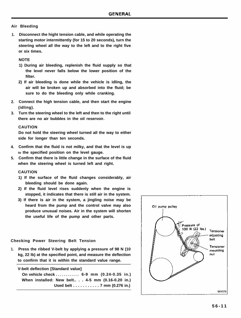
Checking Power Steering Belt Tension
1. Press the ribbed V-belt by applying a pressure of 98 N (10kg, 22 lb) at the specified point, and measure the deflection
to confirm that it is within the standard value range.
V-belt deflection [Standard value]
On vehicle check . . . . . . . . . . . . 6-9 mm (0.24-0.35 in.)
When installed: New belt.. . . 4-5 mm (0.16-0.20 in.)Used belt . . . . . . . . . . . 7 mm (0.276 in.)
5 6 - 1 1
GENERAL
2. To adjust the belt tension, loosen the tensioner mounting nutand move the tensioner to obtain the standard value.
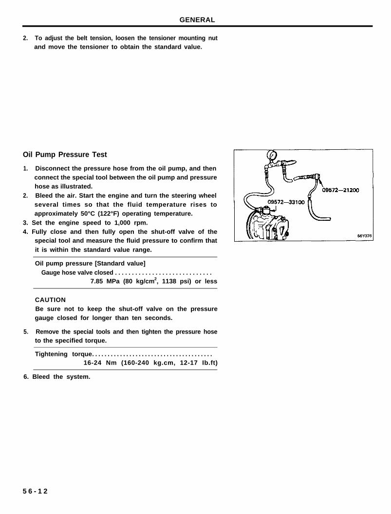
Oil Pump Pressure Test
1. Disconnect the pressure hose from the oil pump, and thenconnect the special tool between the oil pump and pressurehose as illustrated.
2. Bleed the air. Start the engine and turn the steering wheelseveral times so that the fluid temperature rises toapproximately 50°C (122°F) operating temperature.
3. Set the engine speed to 1,000 rpm.4. Fully close and then fully open the shut-off valve of the
special tool and measure the fluid pressure to confirm that
it is within the standard value range.
Oil pump pressure [Standard value]
Gauge hose valve closed . . . . . . . . . . . . . . . . . . . . . . . . . . . . .7.85 MPa (80 kg/cm2, 1138 psi) or less
CAUTIONBe sure not to keep the shut-off valve on the pressuregauge closed for longer than ten seconds.
5. Remove the special tools and then tighten the pressure hoseto the specified torque.
Tightening torque. . . . . . . . . . . . . . . . . . . . . . . . . . . . . . . . . . . . . . .16-24 Nm (160-240 kg.cm, 12-17 Ib.ft)
6. Bleed the system.
5 6 - 1 2
STEERING COLUMN AND SHAFT
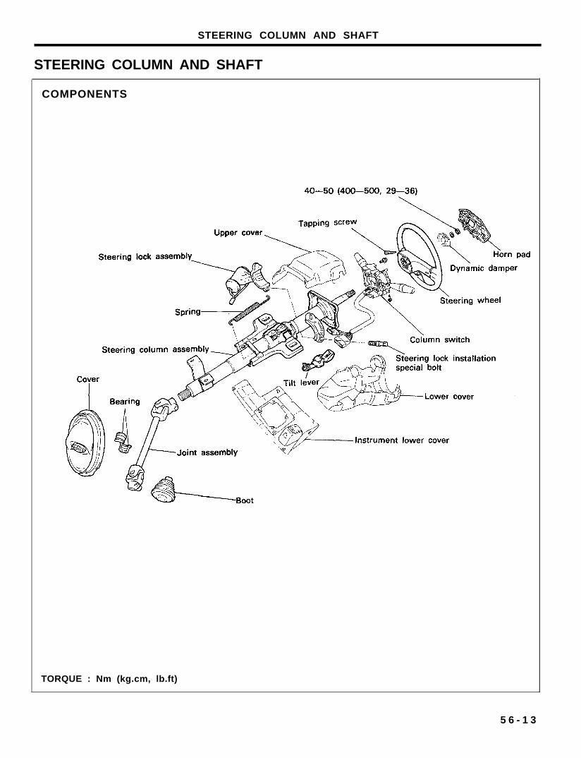
STEERING COLUMN AND SHAFT
COMPONENTS
TORQUE : Nm (kg.cm, lb.ft)
5 6 - 1 3
STEERING COLUMN AND SHAFT
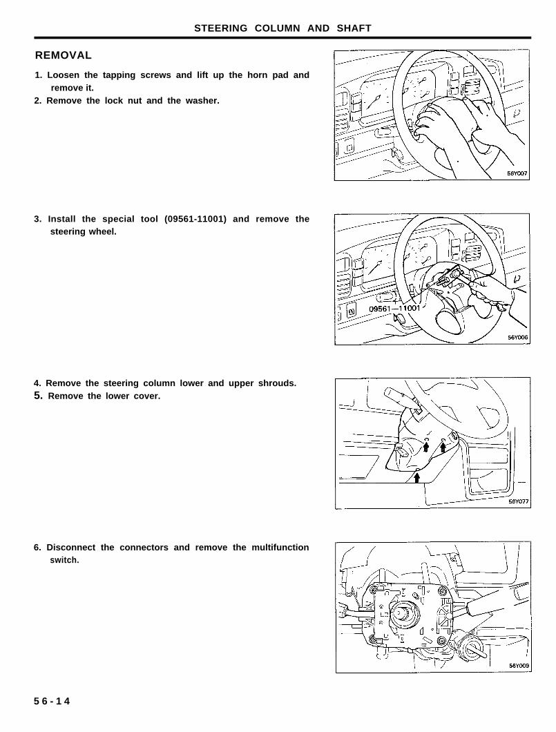
REMOVAL
1. Loosen the tapping screws and lift up the horn pad andremove it.
2. Remove the lock nut and the washer.
3. Install the special tool (09561-11001) and remove thesteering wheel.
4. Remove the steering column lower and upper shrouds.5. Remove the lower cover.
6. Disconnect the connectors and remove the multifunctionswitch.
5 6 - 1 4
STEERING COLUMN AND SHAFT
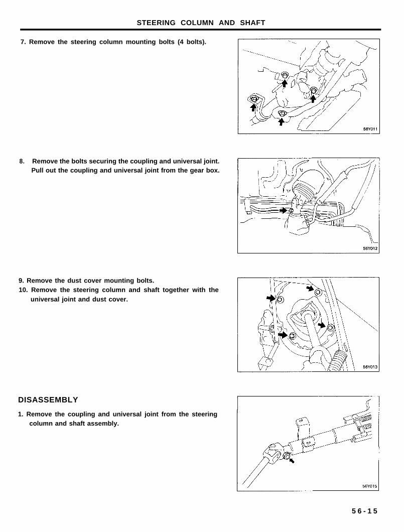
7. Remove the steering column mounting bolts (4 bolts).
8. Remove the bolts securing the coupling and universal joint.Pull out the coupling and universal joint from the gear box.
9. Remove the dust cover mounting bolts.10. Remove the steering column and shaft together with the
universal joint and dust cover.
DISASSEMBLY
1. Remove the coupling and universal joint from the steeringcolumn and shaft assembly.
5 6 - 1 5
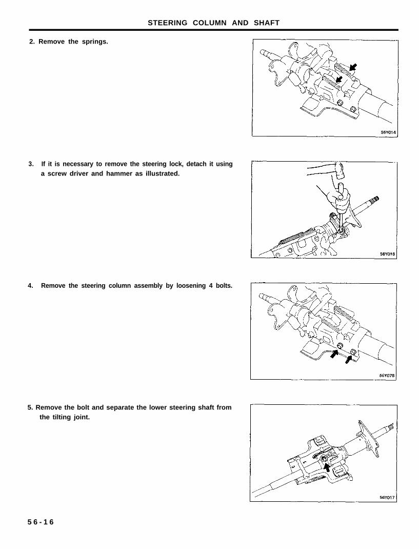
2. Remove the springs.
STEERING COLUMN AND SHAFT
3. If it is necessary to remove the steering lock, detach it using
a screw driver and hammer as illustrated.
4. Remove the steering column assembly by loosening 4 bolts.
5. Remove the bolt and separate the lower steering shaft from
the tilting joint.
5 6 - 1 6
STEERING COLUMN AND SHAFT
INSPECTION
1. Check the steering shaft for damage.2. Check the upper and lower bearings for wear or damage.3. Check the joints for excessive play, damage or rough
movement.4. Check the tilt bracket for cracks or damage.
5. Check the cover or boot for damage.
6. Check that the steering lock mechanism operates properly.
If necessary, replace.
ASSEMBLY
1. Assembly is reverse of the removal procedure.2. When installing the steering lock assembly, match up the
groove on the shaft with the hook on the steering lock in
the steering column.
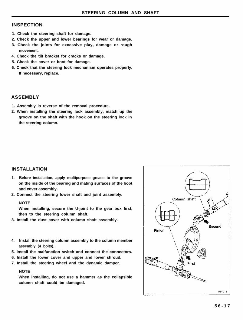
INSTALLATION
1. Before installation, apply multipurpose grease to the grooveon the inside of the bearing and mating surfaces of the bootand cover assembly.
2. Connect the steering lower shaft and joint assembly.
NOTEWhen installing, secure the U-joint to the gear box first,then to the steering column shaft.
3. Install the dust cover with column shaft assembly.
4. Install the steering column assembly to the column memberassembly (4 bolts).
5. Install the malfunction switch and connect the connectors.6. Install the lower cover and upper and lower shroud.7. Install the steering wheel and the dynamic damper.
NOTEWhen installing, do not use a hammer as the collapsiblecolumn shaft could be damaged.
5 6 - 1 7
POWER STEERING GEAR BOX (TRW)
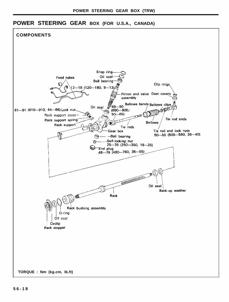
POWER STEERING GEAR BOX (FOR U.S.A., CANADA)
COMPONENTS
TORQUE : Nm (kg.cm, Ib.ft)
5 6 - 1 8
POWER STEERING GEAR BOX (TRW)
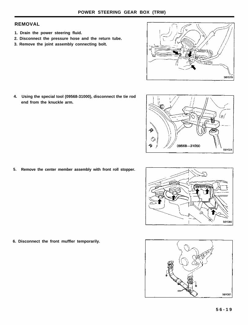
REMOVAL
1. Drain the power steering fluid.2. Disconnect the pressure hose and the return tube.3. Remove the joint assembly connecting bolt.
4.
5.
Using the special tool (09568-31000), disconnect the tie rod
end from the knuckle arm.
Remove the center member assembly with front roll stopper.
6. Disconnect the front muffler temporarily.
5 6 - 1 9
POWER STEERING GEAR BOX (TRW)
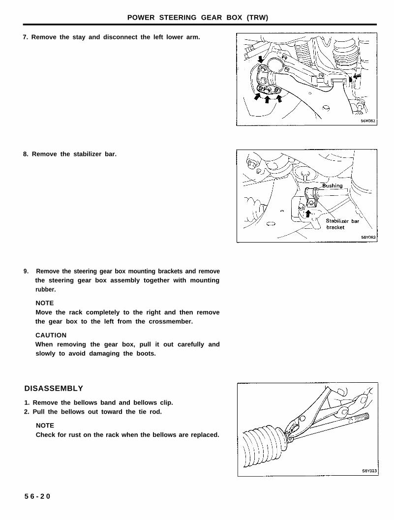
7. Remove the stay and disconnect the left lower arm.
8. Remove the stabilizer bar.
9. Remove the steering gear box mounting brackets and removethe steering gear box assembly together with mountingrubber.
NOTE
Move the rack completely to the right and then removethe gear box to the left from the crossmember.
CAUTIONWhen removing the gear box, pull it out carefully andslowly to avoid damaging the boots.
DISASSEMBLY
1. Remove the bellows band and bellows clip.2. Pull the bellows out toward the tie rod.
NOTE
Check for rust on the rack when the bellows are replaced.
5 6 - 2 0
POWER STEERING GEAR BOX (TRW)
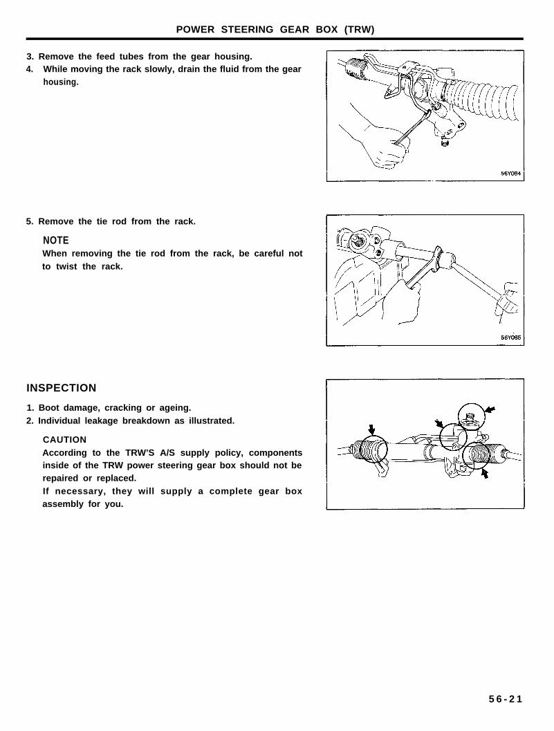
3. Remove the feed tubes from the gear housing.4. While moving the rack slowly, drain the fluid from the gear
housing.
5. Remove the tie rod from the rack.
NOTEWhen removing the tie rod from the rack, be careful not
to twist the rack.
INSPECTION
1. Boot damage, cracking or ageing.
2. Individual leakage breakdown as illustrated.
CAUTION
According to the TRW’S A/S supply policy, componentsinside of the TRW power steering gear box should not berepaired or replaced.
If necessary, they will supply a complete gear boxassembly for you.
5 6 - 2 1
POWER STEERING GEAR BOX (TRW)
ASSEMBLY
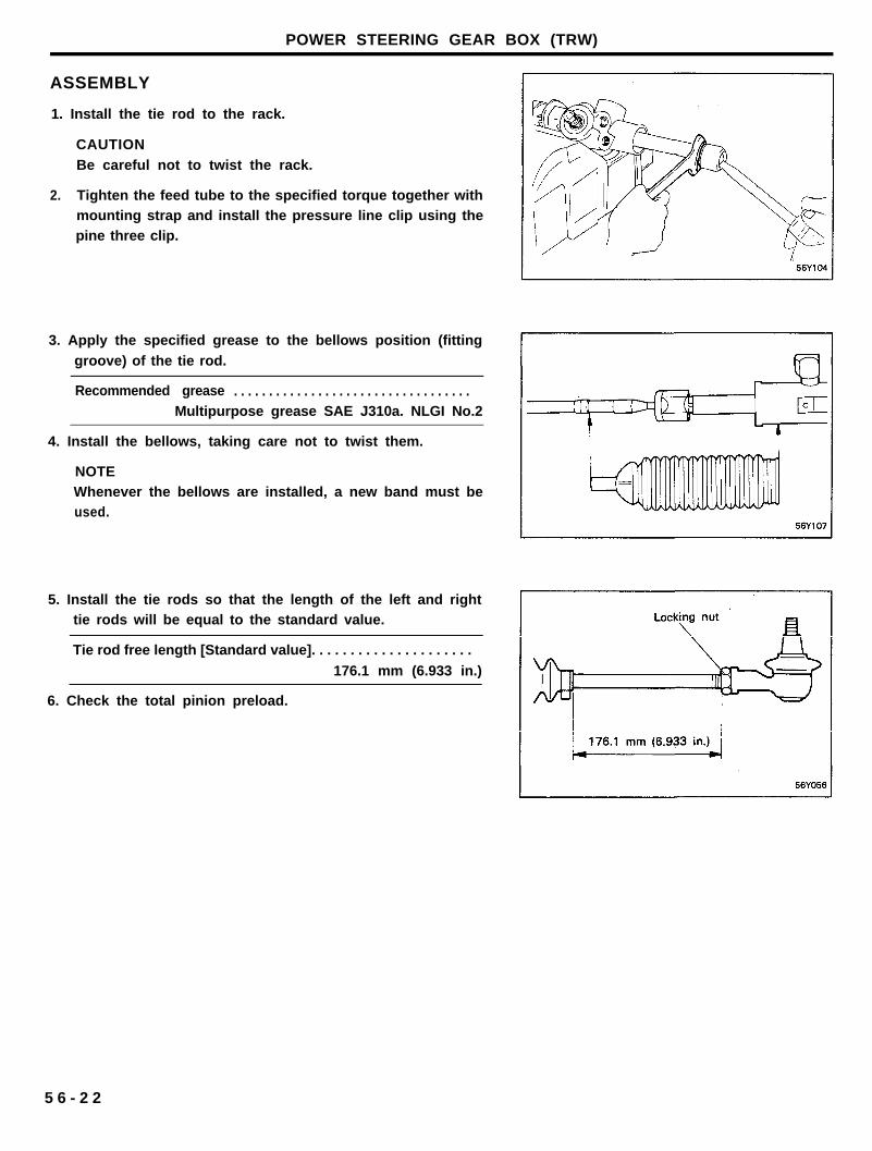
1. Install the tie rod to the rack.
CAUTION
Be careful not to twist the rack.
2. Tighten the feed tube to the specified torque together withmounting strap and install the pressure line clip using thepine three clip.
3. Apply the specified grease to the bellows position (fitting
groove) of the tie rod.
Recommended grease . . . . . . . . . . . . . . . . . . . . . . . . . . . . . . . . . .Multipurpose grease SAE J310a. NLGI No.2
4. Install the bellows, taking care not to twist them.
NOTEWhenever the bellows are installed, a new band must beused.
5. Install the tie rods so that the length of the left and righttie rods will be equal to the standard value.
Tie rod free length [Standard value]. . . . . . . . . . . . . . . . . . . . .
176.1 mm (6.933 in.)
6. Check the total pinion preload.
5 6 - 2 2
POWER STEERING GEAR BOX (TRW)
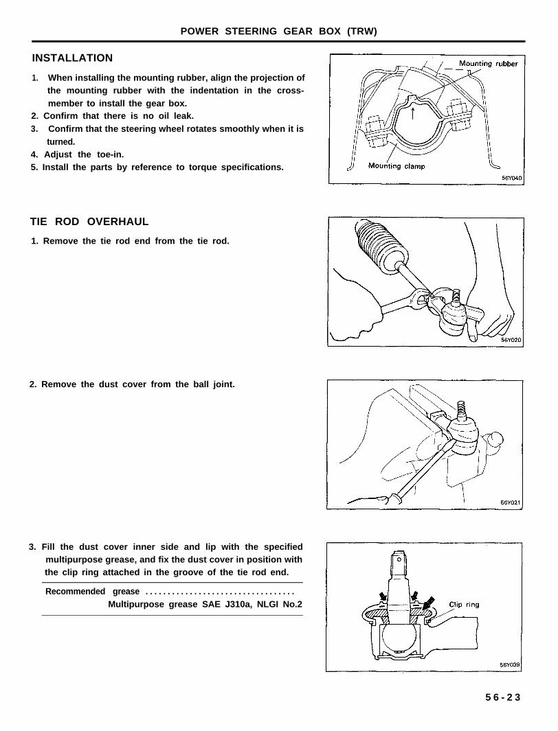
INSTALLATION
1. When installing the mounting rubber, align the projection ofthe mounting rubber with the indentation in the cross-
member to install the gear box.2. Confirm that there is no oil leak.
3. Confirm that the steering wheel rotates smoothly when it is
turned.4. Adjust the toe-in.5. Install the parts by reference to torque specifications.
TIE ROD OVERHAUL
1. Remove the tie rod end from the tie rod.
2. Remove the dust cover from the ball joint.
3. Fill the dust cover inner side and lip with the specifiedmultipurpose grease, and fix the dust cover in position withthe clip ring attached in the groove of the tie rod end.
Recommended grease . . . . . . . . . . . . . . . . . . . . . . . . . . . . . . . . . .
Multipurpose grease SAE J310a, NLGI No.2
5 6 - 2 3
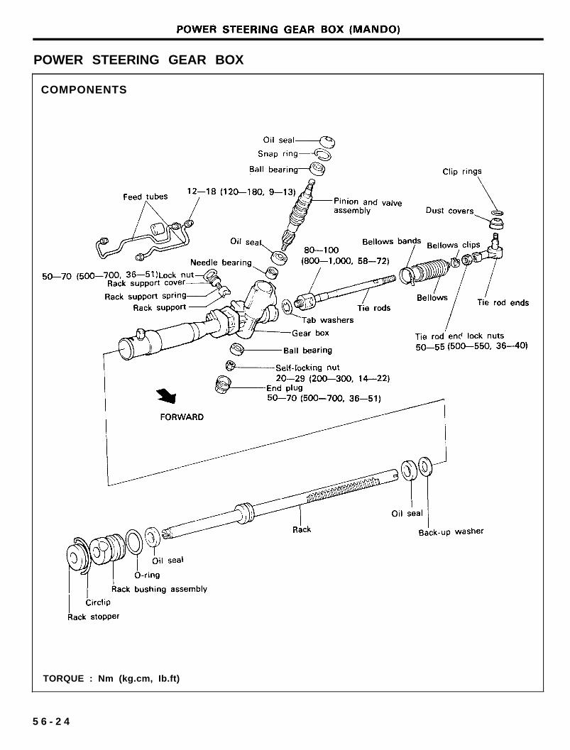
POWER STEERING GEAR BOX
COMPONENTS
TORQUE : Nm (kg.cm, Ib.ft)
5 6 - 2 4
POWER STEERING GEAR BOX (MANDO)
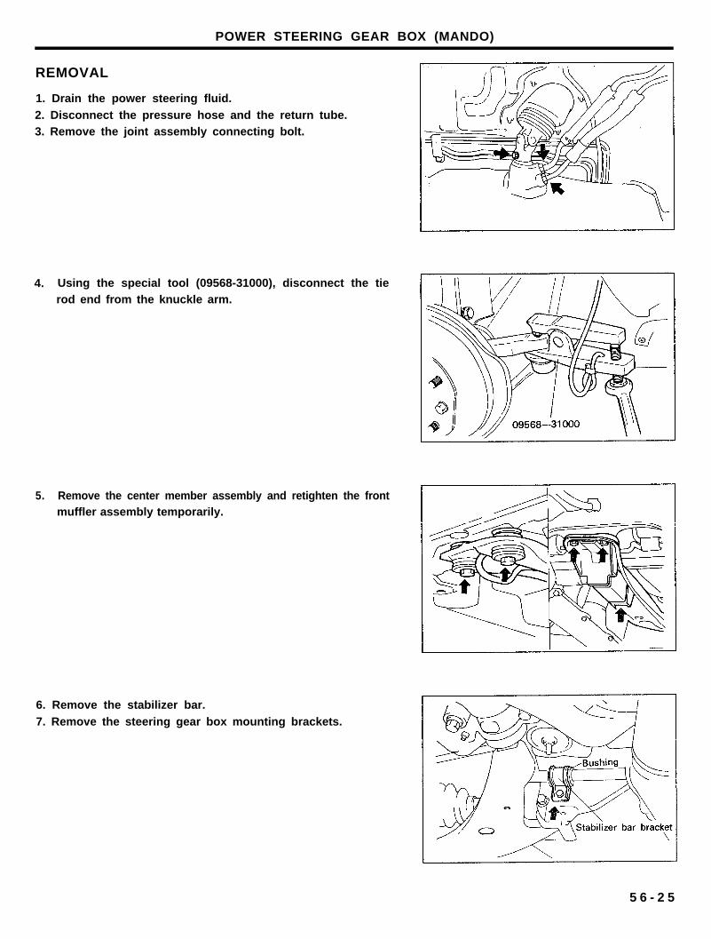
REMOVAL
1. Drain the power steering fluid.
2. Disconnect the pressure hose and the return tube.3. Remove the joint assembly connecting bolt.
4. Using the special tool (09568-31000), disconnect the tierod end from the knuckle arm.
5. Remove the center member assembly and retighten the frontmuffler assembly temporarily.
6. Remove the stabilizer bar.
7. Remove the steering gear box mounting brackets.
5 6 - 2 5
POWER STEERING GEAR BOX (MANDO)
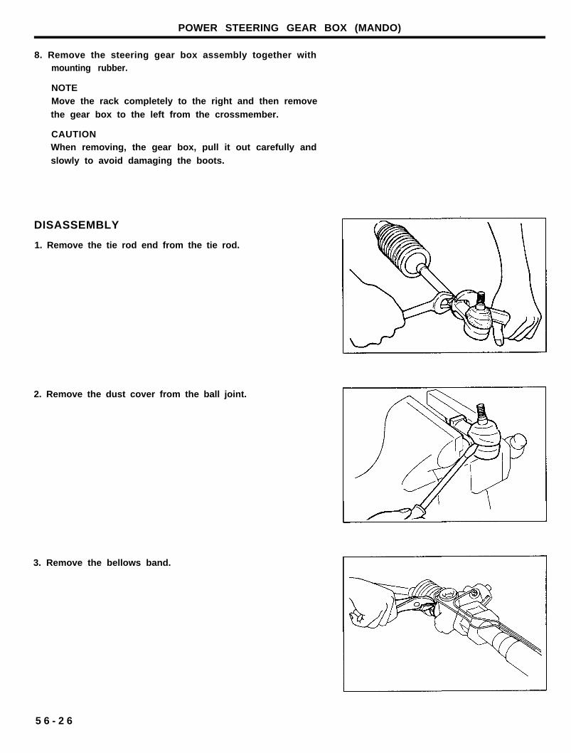
8. Remove the steering gear box assembly together withmounting rubber.
NOTEMove the rack completely to the right and then remove
the gear box to the left from the crossmember.
CAUTIONWhen removing, the gear box, pull it out carefully and
slowly to avoid damaging the boots.
DISASSEMBLY
1. Remove the tie rod end from the tie rod.
2. Remove the dust cover from the ball joint.
3. Remove the bellows band.
5 6 - 2 6
POWER STEERING GEAR BOX (MANDO)
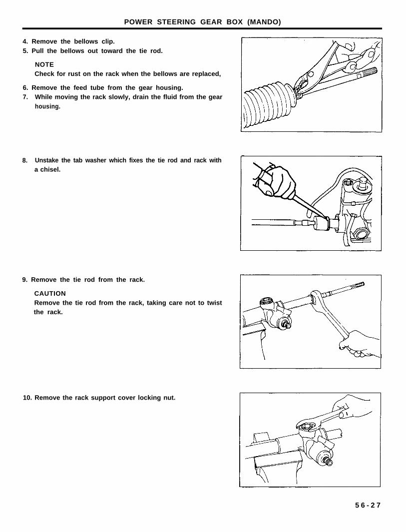
4. Remove the bellows clip.
5. Pull the bellows out toward the tie rod.
NOTECheck for rust on the rack when the bellows are replaced,
6. Remove the feed tube from the gear housing.7. While moving the rack slowly, drain the fluid from the gear
housing.
8. Unstake the tab washer which fixes the tie rod and rack witha chisel.
9. Remove the tie rod from the rack.
CAUTIONRemove the tie rod from the rack, taking care not to twistthe rack.
10. Remove the rack support cover locking nut.
5 6 - 2 7
POWER STEERING GEAR BOX (MANDO).
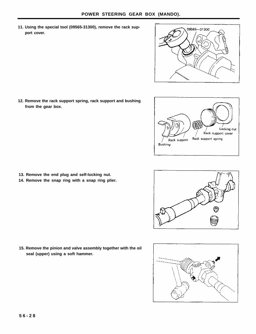
11. Using the special tool (09565-31300), remove the rack sup-port cover.
12. Remove the rack support spring, rack support and bushingfrom the gear box.
13. Remove the end plug and self-locking nut.14. Remove the snap ring with a snap ring plier.
15. Remove the pinion and valve assembly together with the oilseal (upper) using a soft hammer.
5 6 - 2 8
POWER STEERING GEAR BOX (MANDO)
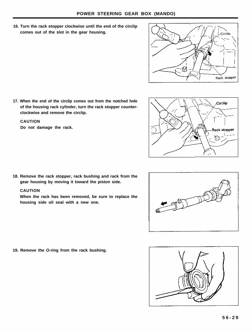
16. Turn the rack stopper clockwise until the end of the circlip
comes out of the slot in the gear housing.
17. When the end of the circlip comes out from the notched holeof the housing rack cylinder, turn the rack stopper counter-clockwise and remove the circlip.
CAUTION
Do not damage the rack.
18. Remove the rack stopper, rack bushing and rack from thegear housing by moving it toward the piston side.
CAUTION
When the rack has been removed, be sure to replace thehousing side oil seal with a new one.
19. Remove the O-ring from the rack bushing.
5 6 - 2 9
POWER STEERING GEAR BOX (MANDO)
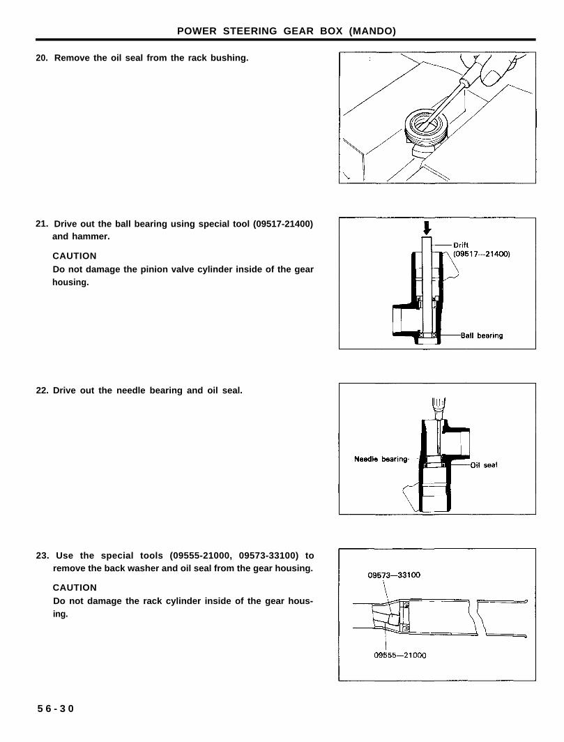
20. Remove the oil seal from the rack bushing.
21. Drive out the ball bearing using special tool (09517-21400)and hammer.
CAUTION
Do not damage the pinion valve cylinder inside of the gearhousing.
22. Drive out the needle bearing and oil seal.
23. Use the special tools (09555-21000, 09573-33100) toremove the back washer and oil seal from the gear housing.
CAUTION
Do not damage the rack cylinder inside of the gear hous-ing.
5 6 - 3 0
POWER STEERING GEAR BOX (MANDO)
INSPECTION
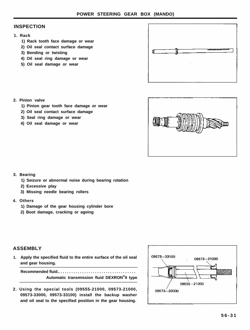
1. Rack1) Rack tooth face damage or wear2) Oil seal contact surface damage3) Bending or twisting4) Oil seal ring damage or wear5) Oil seal damage or wear
2. Pinion valve1) Pinion gear tooth face damage or wear
2) Oil seal contact surface damage3) Seal ring damage or wear
4) Oil seal damage or wear
3. Bearing1) Seizure or abnormal noise during bearing rotation
2) Excessive play3) Missing needle bearing rollers
4. Others1) Damage of the gear housing cylinder bore2) Boot damage, cracking or ageing
ASSEMBLY
1. Apply the specified fluid to the entire surface of the oil sealand gear housing.
Recommended fluid.. . . . . . . . . . . . . . . . . . . . . . . . . . . . . . . . . . . .
Automatic transmission fluid DEXRON®II type
2. Using the special tools (09555-21000, 09573-21000,09573-33000, 09573-33100) install the backup washerand oil seal to the specified position in the gear housing.
5 6 - 3 1
POWER STEERING GEAR BOX (MANDO)
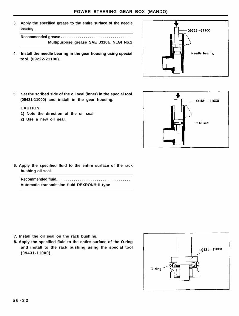
3. Apply the specified grease to the entire surface of the needlebearing.
Recommended grease . . . . . . . . . . . . . . . . . . . . . . . . . . . . . . . . . .Multipurpose grease SAE J310a, NLGI No.2
4. Install the needle bearing in the gear housing using specialtool (09222-21100).
5. Set the scribed side of the oil seal (inner) in the special tool(09431-11000) and install in the gear housing.
CAUTION1) Note the direction of the oil seal.
2) Use a new oil seal.
6. Apply the specified fluid to the entire surface of the rackbushing oil seal.
Recommended fluid.. . . . . . . . . . . . . . . . . . . . . . . . . . . . . . . . . . .
Automatic transmission fluid DEXRON® II type
7. Install the oil seal on the rack bushing.8. Apply the specified fluid to the entire surface of the O-ring
and install to the rack bushing using the special tool
(09431-11000).
5 6 - 3 2
POWER STEERING GEAR BOX (MANDO)
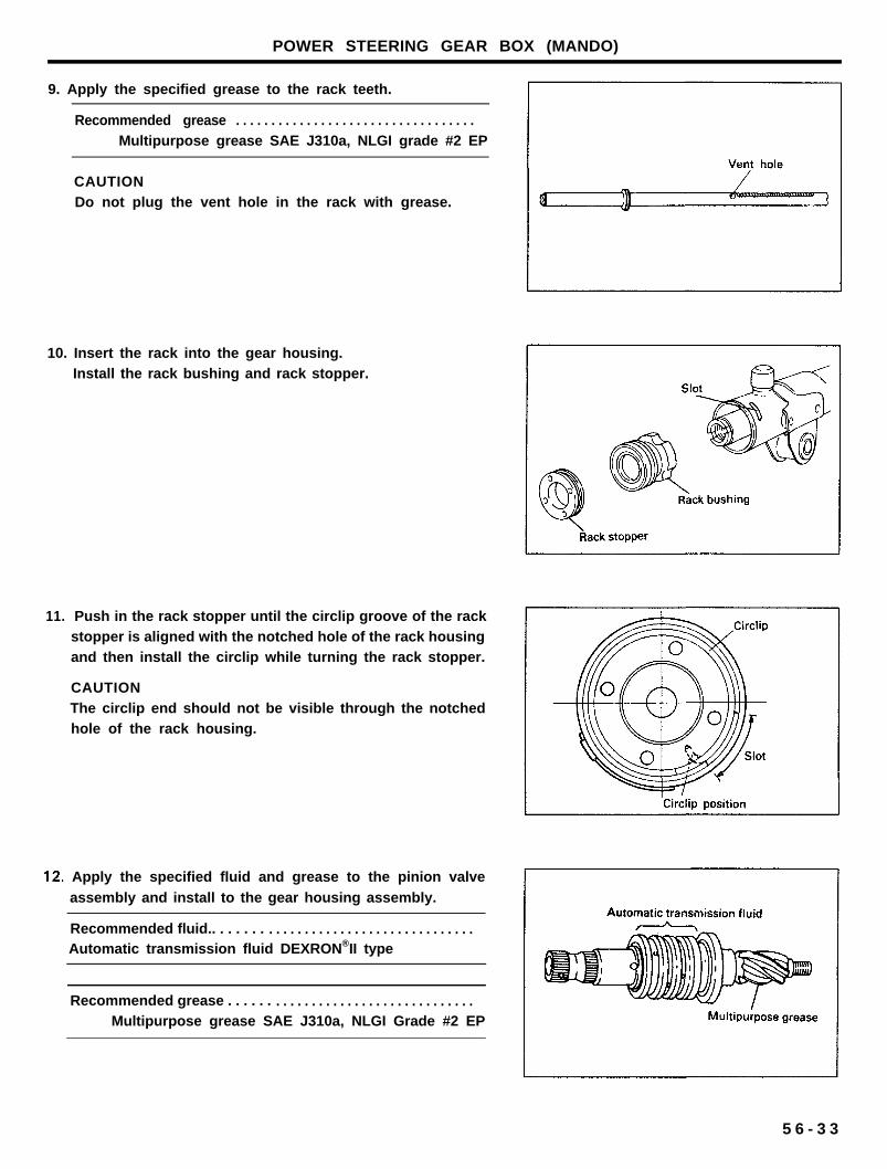
9. Apply the specified grease to the rack teeth.
Recommended grease . . . . . . . . . . . . . . . . . . . . . . . . . . . . . . . . . .Multipurpose grease SAE J310a, NLGI grade #2 EP
CAUTIONDo not plug the vent hole in the rack with grease.
10. Insert the rack into the gear housing.Install the rack bushing and rack stopper.
11. Push in the rack stopper until the circlip groove of the rackstopper is aligned with the notched hole of the rack housingand then install the circlip while turning the rack stopper.
CAUTIONThe circlip end should not be visible through the notchedhole of the rack housing.
Apply the specified fluid and grease to the pinion valve
assembly and install to the gear housing assembly.
Recommended fluid.. . . . . . . . . . . . . . . . . . . . . . . . . . . . . . . . . . . .Automatic transmission fluid DEXRON®II type
Recommended grease . . . . . . . . . . . . . . . . . . . . . . . . . . . . . . . . . .Multipurpose grease SAE J310a, NLGI Grade #2 EP
5 6 - 3 3
POWER STEERING GEAR BOX (MANDO)
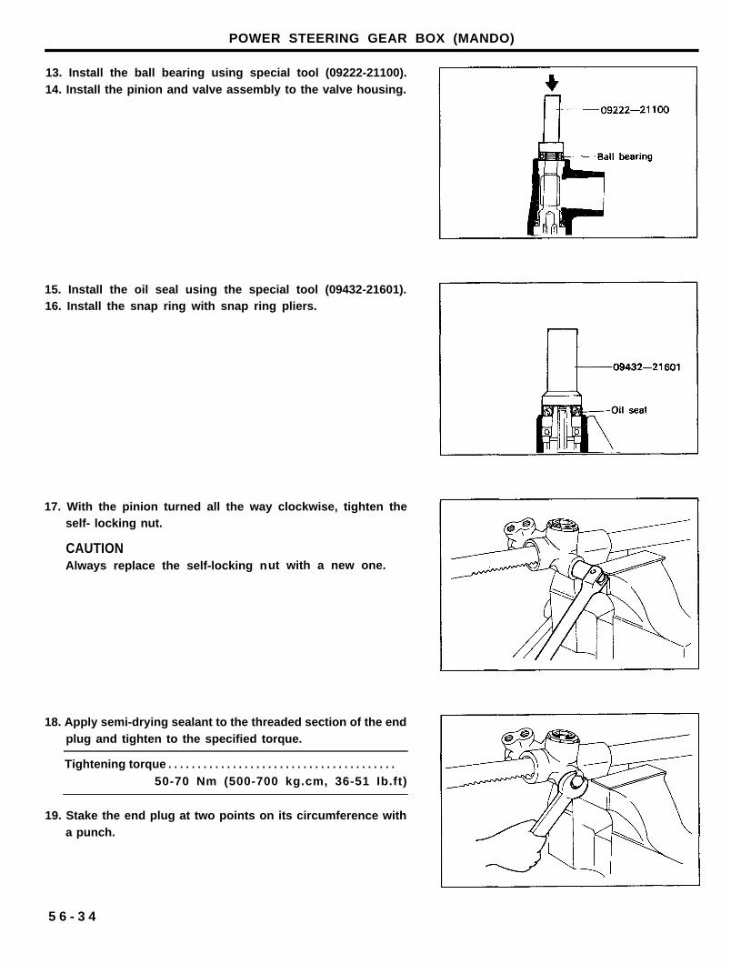
13. Install the ball bearing using special tool (09222-21100).14. Install the pinion and valve assembly to the valve housing.
15. Install the oil seal using the special tool (09432-21601).16. Install the snap ring with snap ring pliers.
17. With the pinion turned all the way clockwise, tighten theself- locking nut.
CAUTIONAlways replace the self-locking nut with a new one.
18. Apply semi-drying sealant to the threaded section of the endplug and tighten to the specified torque.
Tightening torque . . . . . . . . . . . . . . . . . . . . . . . . . . . . . . . . . . . . . . .
50-70 Nm (500-700 kg.cm, 36-51 Ib.ft)
19. Stake the end plug at two points on its circumference witha punch.
5 6 - 3 4
POWER STEERING GEAR BOX (MANDO)
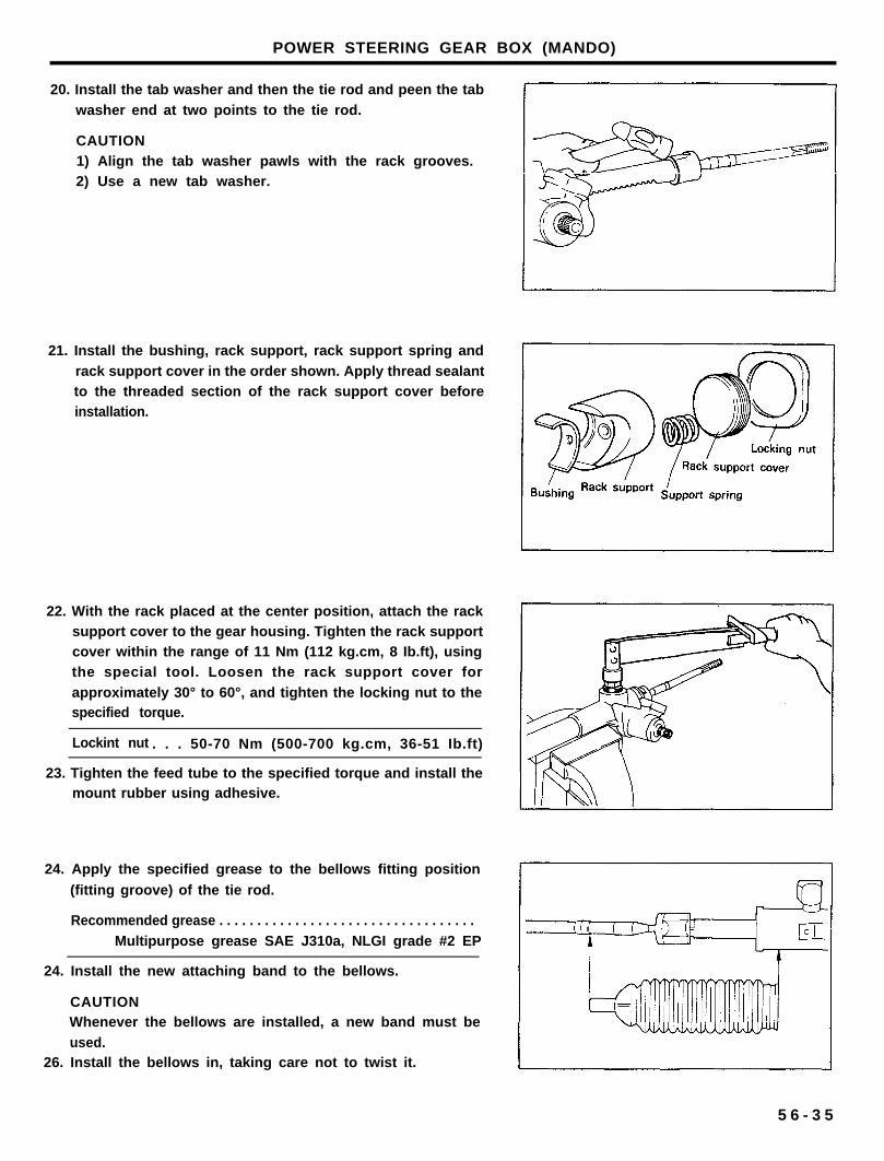
20. Install the tab washer and then the tie rod and peen the tab
washer end at two points to the tie rod.
CAUTION1) Align the tab washer pawls with the rack grooves.2) Use a new tab washer.
21. Install the bushing, rack support, rack support spring and
rack support cover in the order shown. Apply thread sealantto the threaded section of the rack support cover beforeinstallation.
22. With the rack placed at the center position, attach the racksupport cover to the gear housing. Tighten the rack supportcover within the range of 11 Nm (112 kg.cm, 8 Ib.ft), usingthe special tool. Loosen the rack support cover for
approximately 30° to 60°, and tighten the locking nut to thespecified torque.
Lockint nut . . . 50-70 Nm (500-700 kg.cm, 36-51 Ib.ft)
23. Tighten the feed tube to the specified torque and install themount rubber using adhesive.
24. Apply the specified grease to the bellows fitting position
(fitting groove) of the tie rod.
Recommended grease . . . . . . . . . . . . . . . . . . . . . . . . . . . . . . . . . .
Multipurpose grease SAE J310a, NLGI grade #2 EP
24. Install the new attaching band to the bellows.
CAUTIONWhenever the bellows are installed, a new band must be
used.26. Install the bellows in, taking care not to twist it.
5 6 - 3 5
POWER STEERING GEAR BOX (MANDO)
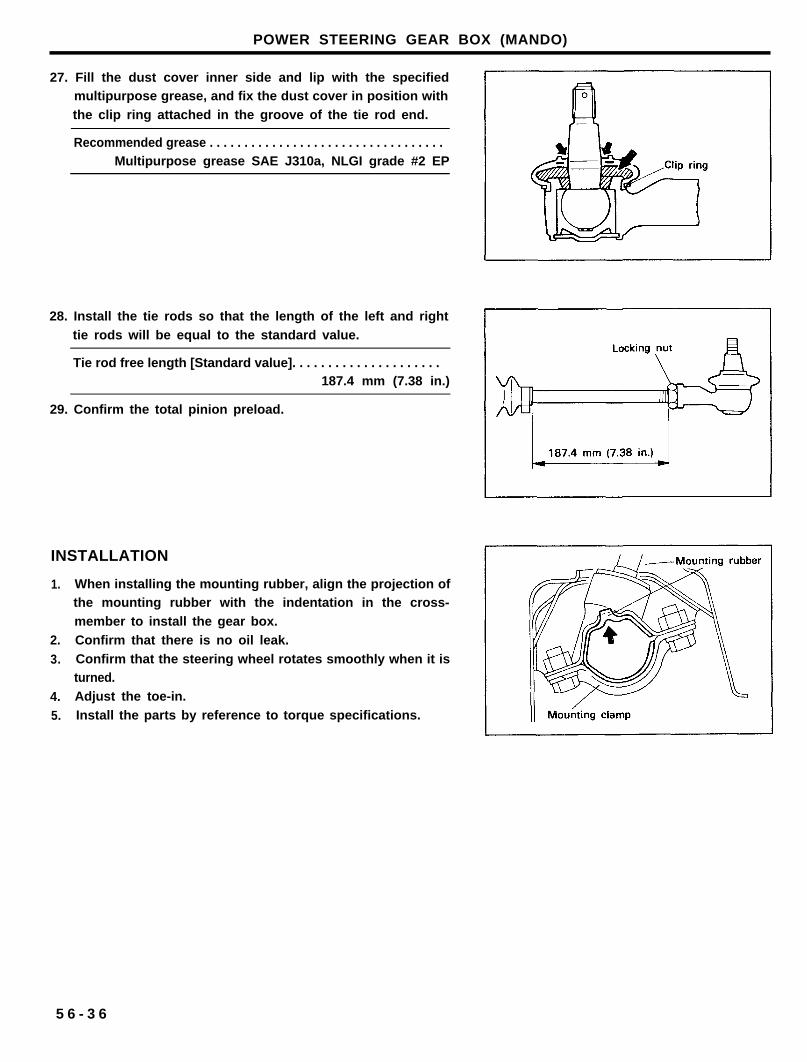
27. Fill the dust cover inner side and lip with the specifiedmultipurpose grease, and fix the dust cover in position with
the clip ring attached in the groove of the tie rod end.
Recommended grease . . . . . . . . . . . . . . . . . . . . . . . . . . . . . . . . . .Multipurpose grease SAE J310a, NLGI grade #2 EP
28. Install the tie rods so that the length of the left and right
tie rods will be equal to the standard value.
Tie rod free length [Standard value]. . . . . . . . . . . . . . . . . . . . .187.4 mm (7.38 in.)
29. Confirm the total pinion preload.
INSTALLATION
1.
2.
3.
4.
5.
When installing the mounting rubber, align the projection ofthe mounting rubber with the indentation in the cross-
member to install the gear box.
Confirm that there is no oil leak.
Confirm that the steering wheel rotates smoothly when it isturned.
Adjust the toe-in.
Install the parts by reference to torque specifications.
5 6 - 3 6
POWER STEERING OIL PUMP
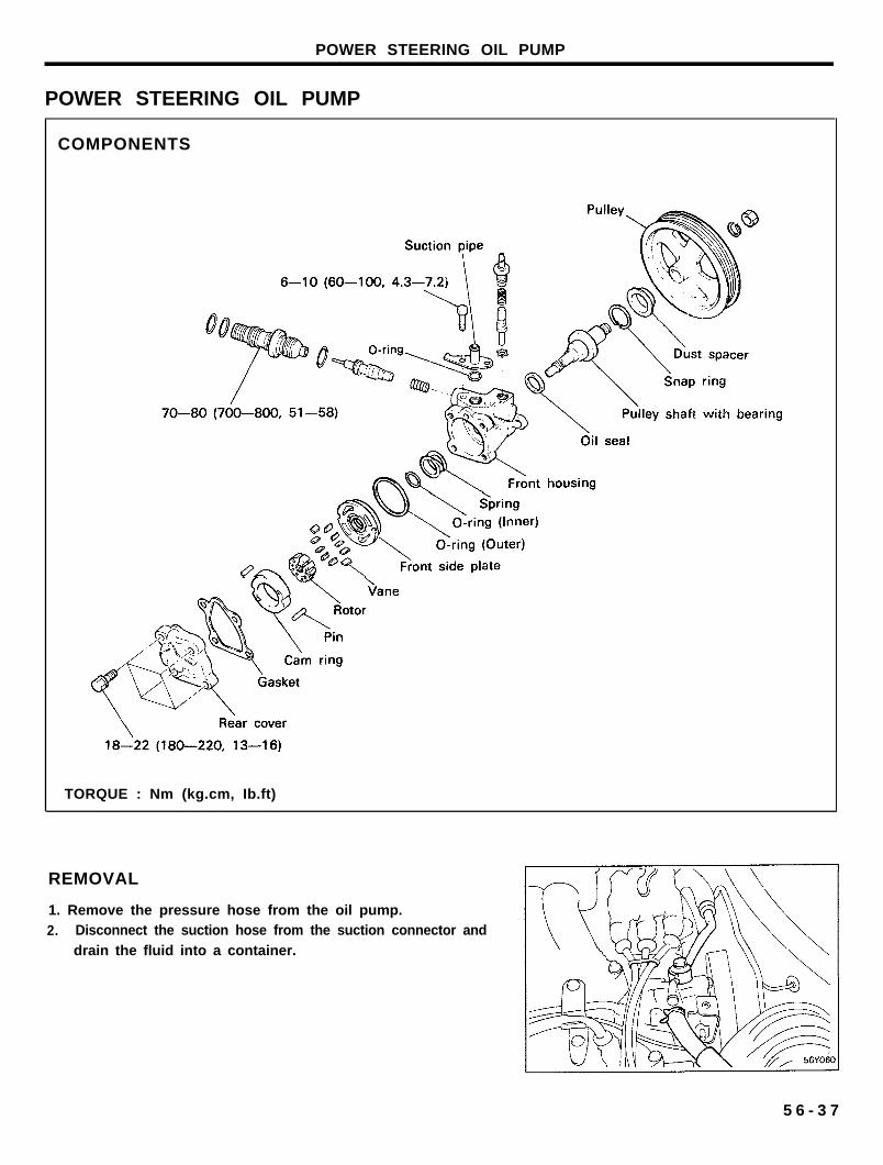
POWER STEERING OIL PUMP
COMPONENTS
TORQUE : Nm (kg.cm, Ib.ft)
REMOVAL
1. Remove the pressure hose from the oil pump.2. Disconnect the suction hose from the suction connector and
drain the fluid into a container.
5 6 - 3 7
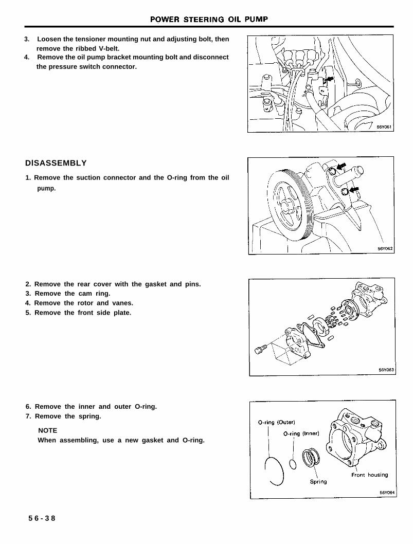
3. Loosen the tensioner mounting nut and adjusting bolt, thenremove the ribbed V-belt.
4. Remove the oil pump bracket mounting bolt and disconnectthe pressure switch connector.
DlSASSEMBLY
1. Remove the suction connector and the O-ring from the oil
pump.
2. Remove the rear cover with the gasket and pins.3. Remove the cam ring.4. Remove the rotor and vanes.
5. Remove the front side plate.
6. Remove the inner and outer O-ring.
7. Remove the spring.
NOTE
When assembling, use a new gasket and O-ring.
5 6 - 3 8
POWER STEERING OIL PUMP
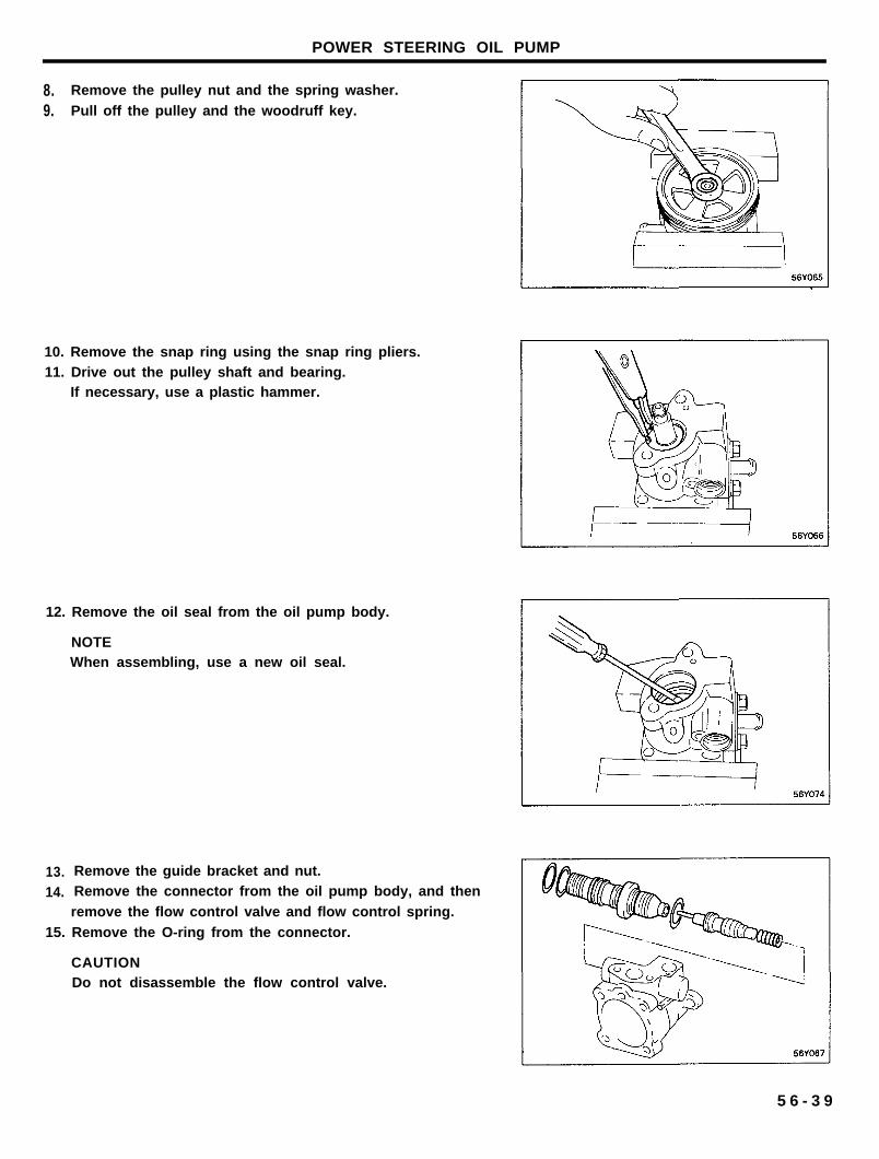
8. Remove the pulley nut and the spring washer.
9. Pull off the pulley and the woodruff key.
10. Remove the snap ring using the snap ring pliers.11. Drive out the pulley shaft and bearing.
If necessary, use a plastic hammer.
12. Remove the oil seal from the oil pump body.
NOTEWhen assembling, use a new oil seal.
13. Remove the guide bracket and nut.
14. Remove the connector from the oil pump body, and then
remove the flow control valve and flow control spring.
15. Remove the O-ring from the connector.
CAUTIONDo not disassemble the flow control valve.
5 6 - 3 9
POWER STEERING OIL PUMP
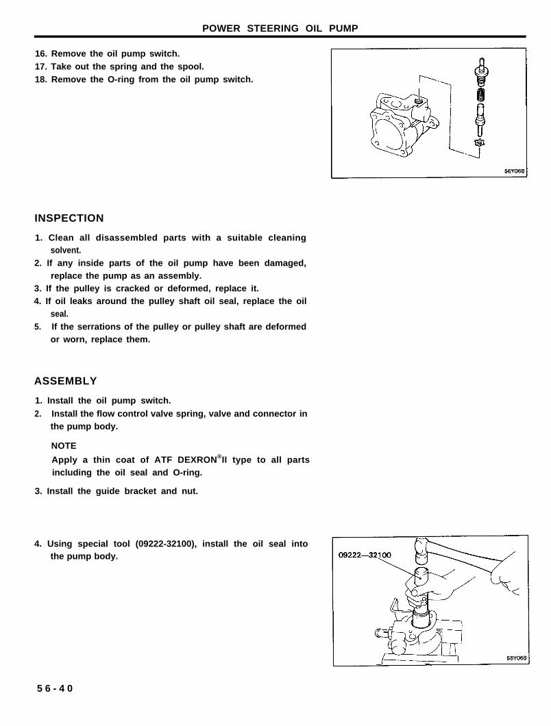
16. Remove the oil pump switch.
17. Take out the spring and the spool.
18. Remove the O-ring from the oil pump switch.
INSPECTION
1. Clean all disassembled parts with a suitable cleaningsolvent.
2. If any inside parts of the oil pump have been damaged,replace the pump as an assembly.
3. If the pulley is cracked or deformed, replace it.4. If oil leaks around the pulley shaft oil seal, replace the oil
seal.
5. If the serrations of the pulley or pulley shaft are deformedor worn, replace them.
ASSEMBLY
1. Install the oil pump switch.
2. Install the flow control valve spring, valve and connector inthe pump body.
NOTE
Apply a thin coat of ATF DEXRON®II type to all partsincluding the oil seal and O-ring.
3. Install the guide bracket and nut.
4. Using special tool (09222-32100), install the oil seal intothe pump body.
5 6 - 4 0
POWER STEERING OIL PUMP
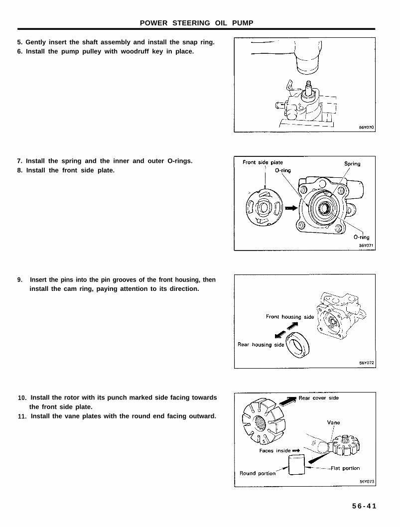
5. Gently insert the shaft assembly and install the snap ring.6. Install the pump pulley with woodruff key in place.
7. Install the spring and the inner and outer O-rings.
8. Install the front side plate.
9. Insert the pins into the pin grooves of the front housing, then
10.
11.
install the cam ring, paying attention to its direction.
Install the rotor with its punch marked side facing towards
the front side plate.Install the vane plates with the round end facing outward.
5 6 - 4 1
POWER STEERING OIL PUMP
12. Install the gasket and rear cover.13. Tighten the suction connector.
INSTALLATION
1. Install the oil pump to the oil pump bracket.2. Install the suction hose.3. Install the ribbed V-belt and adjust the belt tension.
4. Connect the pressure hose to the oil pump, and the suctionhose to the oil reservoir.
NOTE
Install the hoses so that they are not twisted and they donot come in contact with any other parts.
5. Replenish the reservoir.
Recommended fluid.. . . . . . . . . . . . . . . . ATF DEXRON®ll type
6. Bleed the system.
7. Check the oil pump pressure.8. Install parts by reference to the torque specification.
5 6 - 4 2
POWER STEERING HOSES
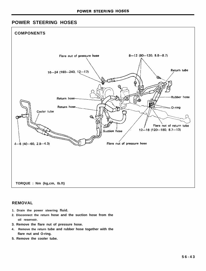
COMPONENTS
TORQUE : Nm (kg,cm, Ib.ft)
REMOVAL
1. Drain the power steering fluid.2. Disconnect the return hose and the suction hose from the
oil reservoir.
3. Remove the flare nut of pressure hose.4. Remove the return tube and rubber hose together with the
flare nut and O-ring.
5. Remove the cooler tube.
5 6 - 4 3
Recommended