HOOK-UPAPPLICATION
DIAGRAMS
Sectio
n 2
HOOK-U
P D
IAGRAM
S
84
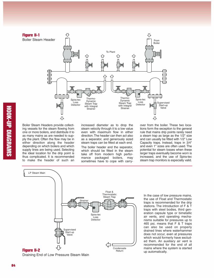
Boiler Steam Headers provide collect-ing vessels for the steam flowing fromone or more boilers, and distribute it toas many mains as are needed to sup-ply the plant. Often the flow may be ineither direction along the headerdepending on which boilers and whichsupply lines are being used. Selectingthe ideal location for the drip point isthus complicated. It is recommendedto make the header of such an
Figure II-1Boiler Steam Header
To Plant
Spira-tecLoss
Detector
Thermo-Dynamic
Steam Trapwith Integral
Strainer
Figure II-2Draining End of Low Pressure Steam Main
FromBoiler
Spira-tecLoss
Detector
Thermo-Dynamic
Steam Trapwith Integral
Strainer
Float &ThermostaticSteam Trap
Spira-tecLoss
Detector
Strainer
CondensateReturn
In the case of low pressure mains,the use of Float and Thermostatictraps is recommended for the dripstations. The introduction of F & Ttraps with steel bodies, third gen-eration capsule type or bimetallicair vents, and operating mecha-nisms suitable for pressures up to465 psi, means that F & T trapscan also be used on properlydrained lines where waterhammerdoes not occur, even at pressureswhich would formerly have exclud-ed them. An auxiliary air vent isrecommended for the end of allmains where the system is startedup automatically.
LP Steam Main
increased diameter as to drop thesteam velocity through it to a low valueeven with maximum flow in eitherdirection.The header can then act alsoas a separator, and generously sizedsteam traps can be fitted at each end.
The boiler header and the separator,which should be fitted in the steamtake off from modern high perfor-mance packaged boilers, maysometimes have to cope with carry-
over from the boiler. These two loca-tions form the exception to the generalrule that mains drip points rarely needa steam trap as large as the 1/2" sizeand can usually be fitted with 1/2" LowCapacity traps. Instead, traps in 3/4"and even 1" sizes are often used. Thepotential for steam losses when theselarger traps eventually become worn isincreased, and the use of Spira-tecsteam trap monitors is especially valid.
SupervisedStart-up
Valve
SupervisedStart-up
Valve
85
HOOK-U
P D
IAGRAM
S
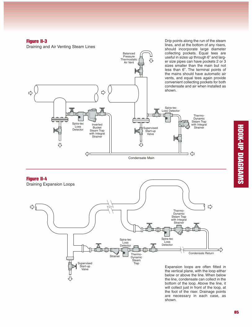
Drip points along the run of the steamlines, and at the bottom of any risers,should incorporate large diametercollecting pockets. Equal tees areuseful in sizes up through 6" and larg-er size pipes can have pockets 2 or 3sizes smaller than the main but notless than 6". The terminal points ofthe mains should have automatic airvents, and equal tees again provideconvenient collecting pockets for bothcondensate and air when installed asshown.
Figure II-3Draining and Air Venting Steam Lines
InvertedBucket
Steam Trapwith Integral
Strainer
Spira-tecLoss
Detector
BalancedPressure
ThermostaticAir Vent
Condensate Main
Thermo-Dynamic
Steam Trapwith Integral
Strainer
Spira-tecLoss Detector
Figure II-4Draining Expansion Loops
Condensate Return
Thermo-Dynamic
Steam Trapwith Integral
Strainer
Thermo-DynamicSteamTrap
Spira-tecLoss
Detector
Spira-tecLoss
Detector
Expansion loops are often fitted inthe vertical plane, with the loop eitherbelow or above the line. When belowthe line, condensate can collect in thebottom of the loop. Above the line, itwill collect just in front of the loop, atthe foot of the riser. Drainage pointsare necessary in each case, asshown.
SupervisedStart-up
Valve
SupervisedStart-up
Valve
Strainer
86
HOOK-U
P D
IAGRAM
S
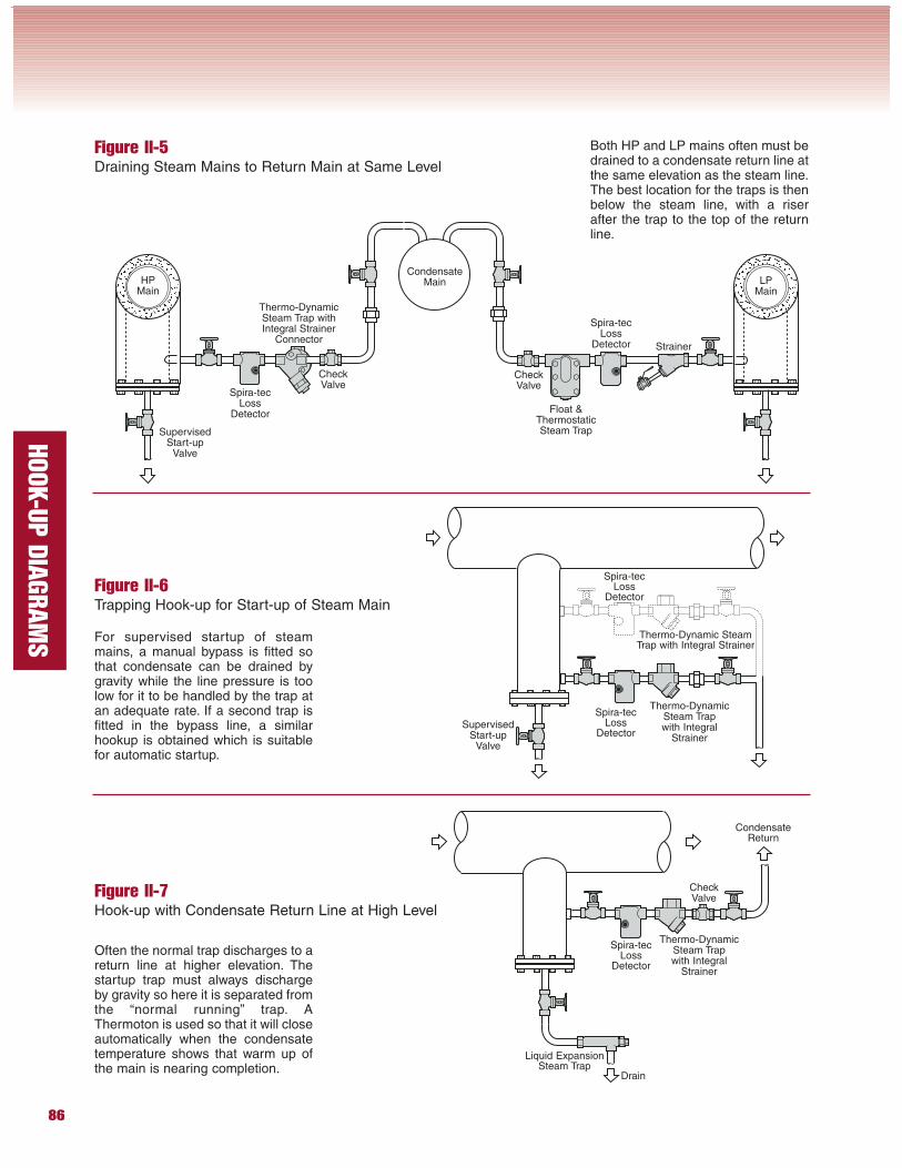
Both HP and LP mains often must bedrained to a condensate return line atthe same elevation as the steam line.The best location for the traps is thenbelow the steam line, with a riserafter the trap to the top of the returnline.
Figure II-5Draining Steam Mains to Return Main at Same Level
Spira-tecLoss
Detector
Thermo-DynamicSteam Trap withIntegral Strainer
Connector
Float &ThermostaticSteam Trap
Strainer
Spira-tecLoss
Detector
CondensateMainHP
MainLP
Main
For supervised startup of steammains, a manual bypass is fitted sothat condensate can be drained bygravity while the line pressure is toolow for it to be handled by the trap atan adequate rate. If a second trap isfitted in the bypass line, a similarhookup is obtained which is suitablefor automatic startup.
Figure II-6Trapping Hook-up for Start-up of Steam Main
Often the normal trap discharges to areturn line at higher elevation. Thestartup trap must always dischargeby gravity so here it is separated fromthe “normal running” trap. AThermoton is used so that it will closeautomatically when the condensatetemperature shows that warm up ofthe main is nearing completion.
Figure II-7Hook-up with Condensate Return Line at High Level
Thermo-DynamicSteam Trapwith Integral
Strainer
Spira-tecLoss
Detector
Thermo-Dynamic SteamTrap with Integral Strainer
Spira-tecLoss
Detector
Thermo-DynamicSteam Trapwith Integral
Strainer
Spira-tecLoss
Detector
Liquid ExpansionSteam Trap
Drain
CondensateReturn
CheckValve
CheckValve
SupervisedStart-up
Valve
CheckValve
SupervisedStart-up
Valve
87
HOOK-U
P D
IAGRAM
S
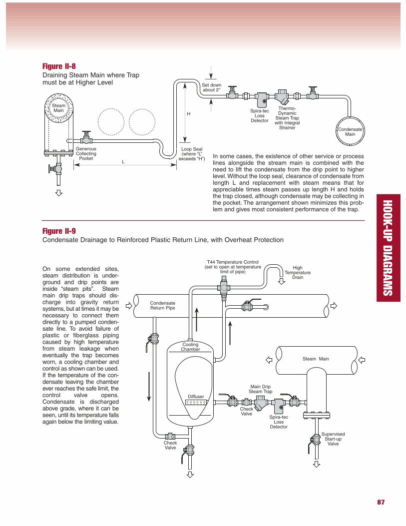
In some cases, the existence of other service or processlines alongside the stream main is combined with theneed to lift the condensate from the drip point to higherlevel. Without the loop seal, clearance of condensate fromlength L and replacement with steam means that forappreciable times steam passes up length H and holdsthe trap closed, although condensate may be collecting inthe pocket. The arrangement shown minimizes this prob-lem and gives most consistent performance of the trap.
Thermo-Dynamic
Steam Trapwith Integral
Strainer
Spira-tecLoss
Detector
Figure II-8Draining Steam Main where Trapmust be at Higher Level
SteamMain
GenerousCollecting
Loop Seal(where “L”
exceeds “H”)
CondensateMain
L
H
Figure II-9Condensate Drainage to Reinforced Plastic Return Line, with Overheat Protection
Steam Main
CondensateReturn Pipe
CoolingChamber
Diffuser
Spira-tecLoss
Detector
Main DripSteam Trap
HighTemperature
Drain
T44 Temperature Control(set to open at temperature
limit of pipe)On some extended sites,steam distribution is under-ground and drip points areinside “steam pits”. Steammain drip traps should dis-charge into gravity returnsystems, but at times it may benecessary to connect themdirectly to a pumped conden-sate line. To avoid failure ofplastic or fiberglass pipingcaused by high temperaturefrom steam leakage wheneventually the trap becomesworn, a cooling chamber andcontrol as shown can be used.If the temperature of the con-densate leaving the chamberever reaches the safe limit, thecontrol valve opens.Condensate is dischargedabove grade, where it can beseen, until its temperature fallsagain below the limiting value.
CheckValve
CheckValve
SupervisedStart-up
Valve
Set downabout 2"
88
HOOK-U
P D
IAGRAM
S
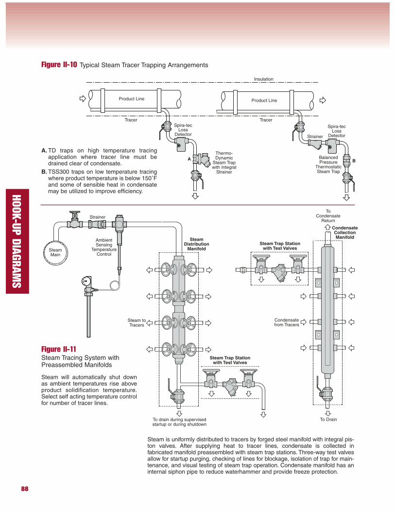
A. TD traps on high temperature tracingapplication where tracer line must bedrained clear of condensate.
B. TSS300 traps on low temperature tracingwhere product temperature is below 150˚Fand some of sensible heat in condensatemay be utilized to improve efficiency.
Figure II-10 Typical Steam Tracer Trapping Arrangements
Thermo-Dynamic
Steam Trapwith Integral
Strainer
BalancedPressure
ThermostaticSteam Trap
Spira-tecLoss
Detector
Spira-tecLoss
DetectorStrainer
TracerTracer
Product Line Product Line
Insulation
A B
Steam will automatically shut downas ambient temperatures rise aboveproduct solidification temperature.Select self acting temperature controlfor number of tracer lines.
Figure II-11Steam Tracing System withPreassembled Manifolds
AmbientSensing
TemperatureControl
Strainer
SteamMain
SteamDistribution
Manifold
CondensateCollectionManifold
Steam Trap Stationwith Test Valves
Steam Trap Stationwith Test Valves
Steam toTracers
Condensatefrom Tracers
To Drain
ToCondensate
Return
To drain during supervisedstartup or during shutdown
Steam is uniformly distributed to tracers by forged steel manifold with integral pis-ton valves. After supplying heat to tracer lines, condensate is collected infabricated manifold preassembled with steam trap stations. Three-way test valvesallow for startup purging, checking of lines for blockage, isolation of trap for main-tenance, and visual testing of steam trap operation. Condensate manifold has aninternal siphon pipe to reduce waterhammer and provide freeze protection.
89
HOOK-U
P D
IAGRAM
S
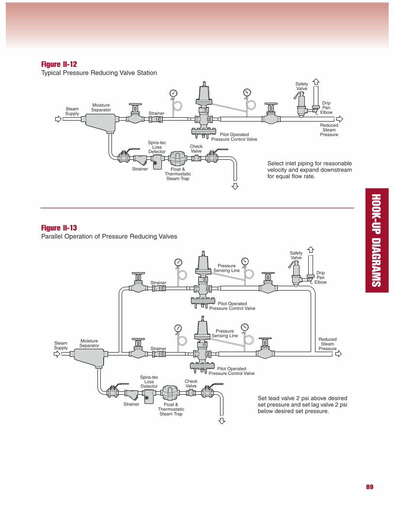
Spira-tecLoss
Detector
StrainerSelect inlet piping for reasonablevelocity and expand downstreamfor equal flow rate.
Figure II-12Typical Pressure Reducing Valve Station
Float &ThermostaticSteam Trap
Strainer
SafetyValve
SteamSupply
Pilot OperatedPressure Control Valve
Figure II-13Parallel Operation of Pressure Reducing Valves
Set lead valve 2 psi above desiredset pressure and set lag valve 2 psibelow desired set pressure.
Spira-tecLoss
Detector
Strainer
SafetyValve
SteamSupply
Pilot OperatedPressure Control Valve
Pilot OperatedPressure Control Valve
Strainer
Strainer
Float &ThermostaticSteam Trap
MoistureSeparator
PressureSensing Line
PressureSensing Line
CheckValve
DripPan
Elbow
MoistureSeparator
ReducedSteam
Pressure
CheckValve
DripPan
Elbow
ReducedSteam
Pressure
90
HOOK-U
P D
IAGRAM
S
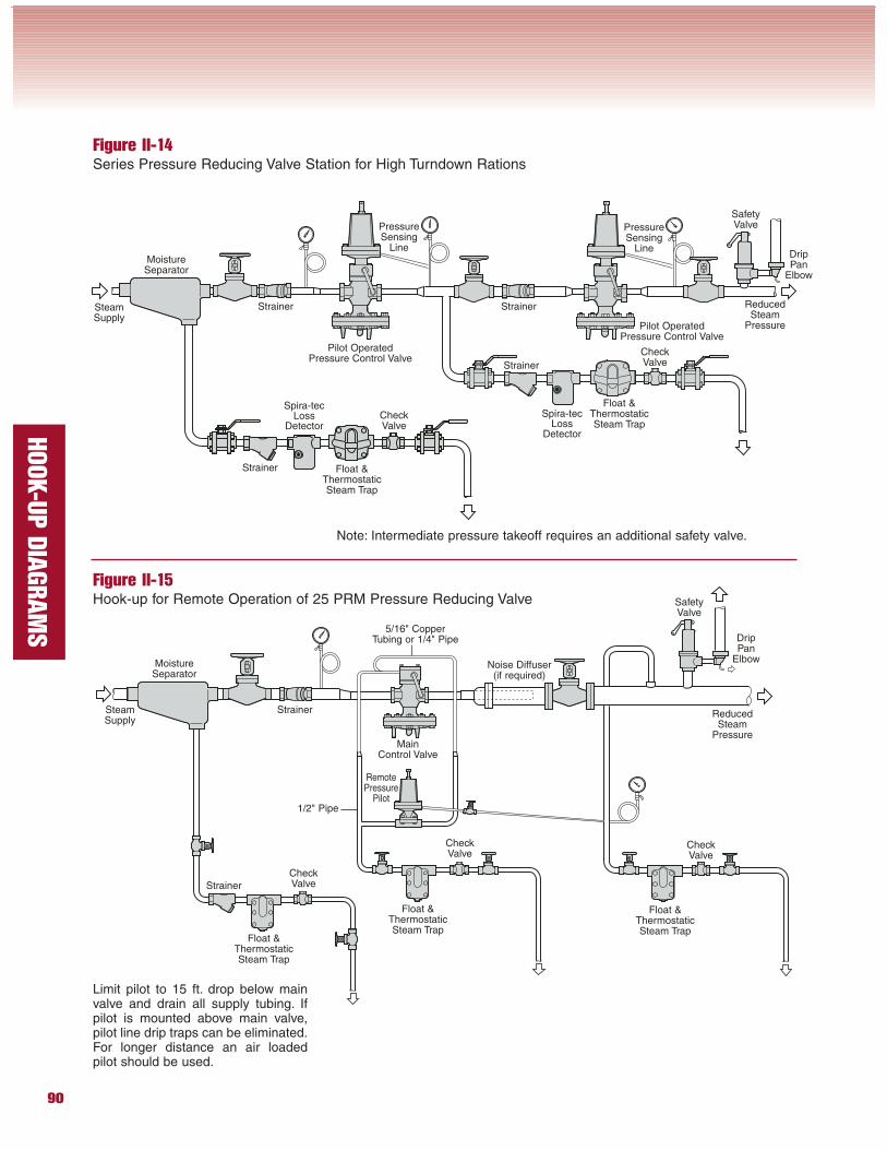
Figure II-14Series Pressure Reducing Valve Station for High Turndown Rations
Note: Intermediate pressure takeoff requires an additional safety valve.
Spira-tecLoss
Detector
Strainer
SafetyValve
SteamSupply
Pilot OperatedPressure Control Valve
Pilot OperatedPressure Control Valve
Strainer Strainer
Float &ThermostaticSteam Trap
MoistureSeparator
PressureSensing
Line
Spira-tecLoss
Detector
Strainer
Float &ThermostaticSteam Trap
PressureSensing
Line
Figure II-15Hook-up for Remote Operation of 25 PRM Pressure Reducing Valve
Float &ThermostaticSteam Trap
Float &ThermostaticSteam Trap
Float &ThermostaticSteam Trap
Strainer
Strainer
SafetyValve
SteamSupply
MoistureSeparator
MainControl Valve
RemotePressure
Pilot
Limit pilot to 15 ft. drop below mainvalve and drain all supply tubing. Ifpilot is mounted above main valve,pilot line drip traps can be eliminated.For longer distance an air loadedpilot should be used.
CheckValve
DripPan
Elbow
ReducedSteam
Pressure
CheckValve
DripPan
Elbow
ReducedSteam
Pressure
CheckValve
CheckValve
CheckValve
Noise Diffuser(if required)
5/16" CopperTubing or 1/4" Pipe
1/2" Pipe
91
HOOK-U
P D
IAGRAM
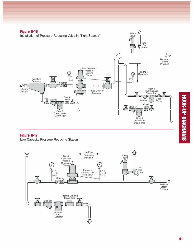
SFigure II-17Low Capacity Pressure Reducing Station
Figure II-16Installation of Pressure Reducing Valve in “Tight Spaces”
PressureSensing LinePitch Down
Spira-tecLoss
Detector
Strainer
Thermo-DynamicSteam Trap
SafetyValve
Strainer
DirectOperatedPressureReducing
Valve
ReducedSteam
Pressure
10 Pipe
DiametersMinimum
Strainer
Strainer
Strainer
Float &ThermostaticSteam Trap
SteamSupply
MoistureSeparator
Float &ThermostaticSteam Trap
Float &ThermostaticSteam Trap
Strainer
SafetyValve
DripPan
Elbow
ReducedSteam
Pressure
CheckValve
CheckValve
CheckValve
Noise Diffuser(if required)
Pilot OperatedPressureControlValve
Ten PipeDiameters
DripPan
Elbow
92
HOOK-U
P D
IAGRAM
S
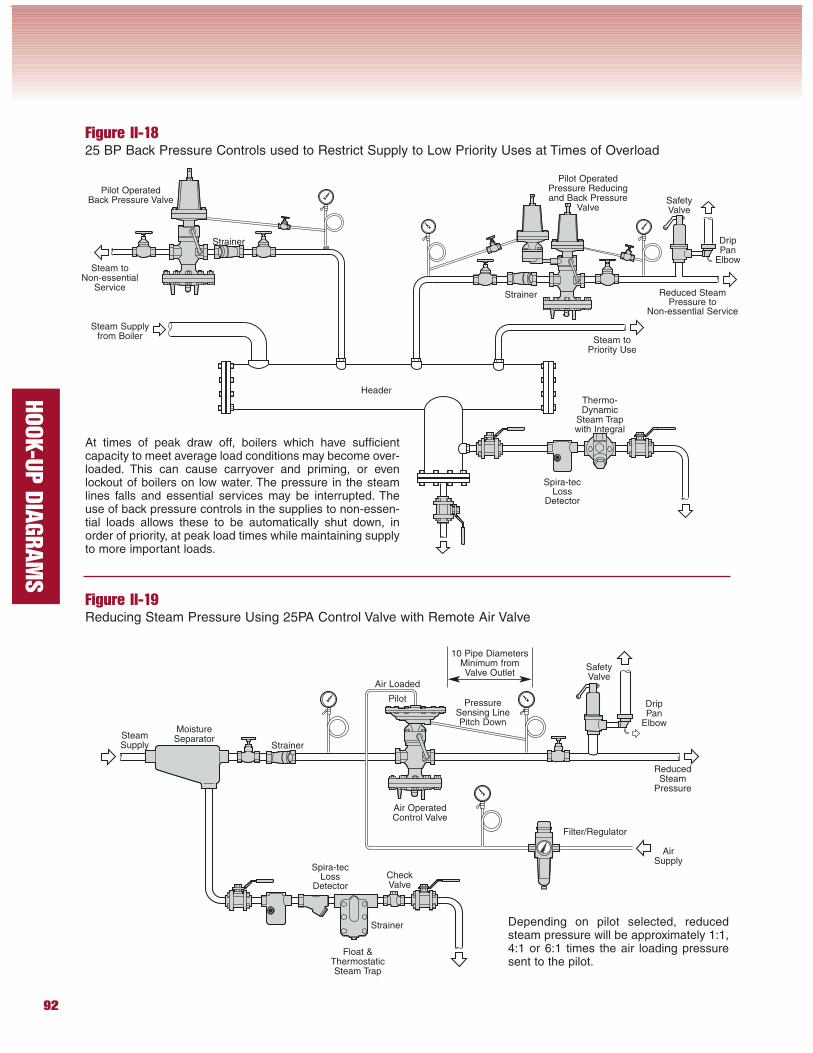
Figure II-1825 BP Back Pressure Controls used to Restrict Supply to Low Priority Uses at Times of Overload
Steam toNon-essential
ServiceStrainer
Thermo-Dynamic
Steam Trapwith Integral
Steam Supplyfrom Boiler
Strainer
Pilot OperatedPressure Reducingand Back Pressure
Valve
Steam toPriority Use
10 Pipe DiametersMinimum fromValve Outlet
At times of peak draw off, boilers which have sufficientcapacity to meet average load conditions may become over-loaded. This can cause carryover and priming, or evenlockout of boilers on low water. The pressure in the steamlines falls and essential services may be interrupted. Theuse of back pressure controls in the supplies to non-essen-tial loads allows these to be automatically shut down, inorder of priority, at peak load times while maintaining supplyto more important loads.
Spira-tecLoss
Detector
Header
Pilot OperatedBack Pressure Valve
Figure II-19Reducing Steam Pressure Using 25PA Control Valve with Remote Air Valve
Depending on pilot selected, reducedsteam pressure will be approximately 1:1,4:1 or 6:1 times the air loading pressuresent to the pilot.
SafetyValve
Spira-tecLoss
Detector
Strainer
Strainer
Float &ThermostaticSteam Trap
Filter/Regulator
SteamSupply
MoistureSeparator
AirSupply
PressureSensing LinePitch Down
Air Loaded
Pilot
Air OperatedControl Valve
DripPan
Elbow
ReducedSteam
Pressure
CheckValve
DripPan
Elbow
SafetyValve
Reduced SteamPressure to
Non-essential Service
93
HOOK-U
P D
IAGRAM
S
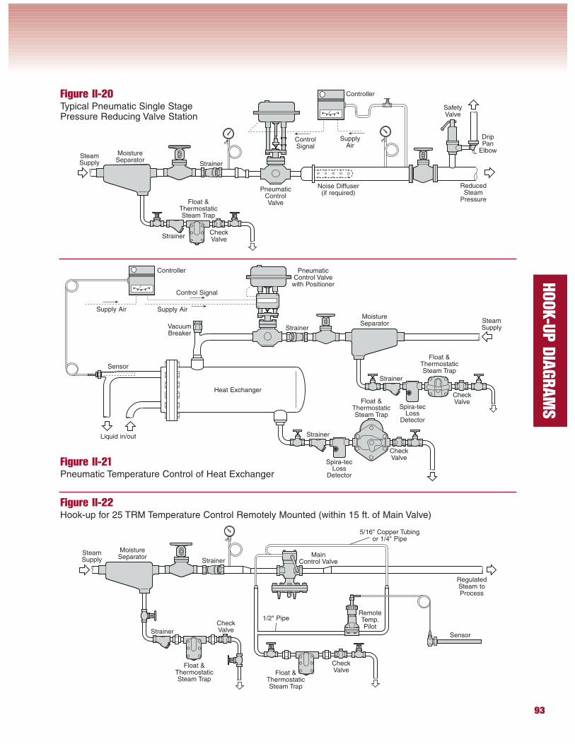
Figure II-20Typical Pneumatic Single StagePressure Reducing Valve Station
Figure II-22Hook-up for 25 TRM Temperature Control Remotely Mounted (within 15 ft. of Main Valve)
StrainerSteamSupply
MoistureSeparator Main
Control Valve
Float &ThermostaticSteam Trap
Strainer
Float &ThermostaticSteam Trap
RegulatedSteam toProcess
Sensor
1/2" Pipe
Figure II-21Pneumatic Temperature Control of Heat Exchanger
StrainerSteamSupply
MoistureSeparator
Float &ThermostaticSteam Trap
Strainer
SafetyValve
VacuumBreaker
Strainer
MoistureSeparator
Float &ThermostaticSteam Trap
Strainer
Spira-tecLoss
Detector
Float &ThermostaticSteam Trap
Strainer
Spira-tecLoss
Detector
SteamSupply
DripPan
Elbow
ReducedSteam
Pressure
Noise Diffuser(if required)
SupplyAir
ControlSignal
PneumaticControlValve
CheckValve
Controller
Controller PneumaticControl Valve
with Positioner
Supply Air
Control Signal
Supply Air
Heat Exchanger
CheckValve
CheckValve
Sensor
Liquid in/out
CheckValve
CheckValve
RemoteTemp.Pilot
5/16" Copper Tubingor 1/4" Pipe
94
HOOK-U
P D
IAGRAM
S
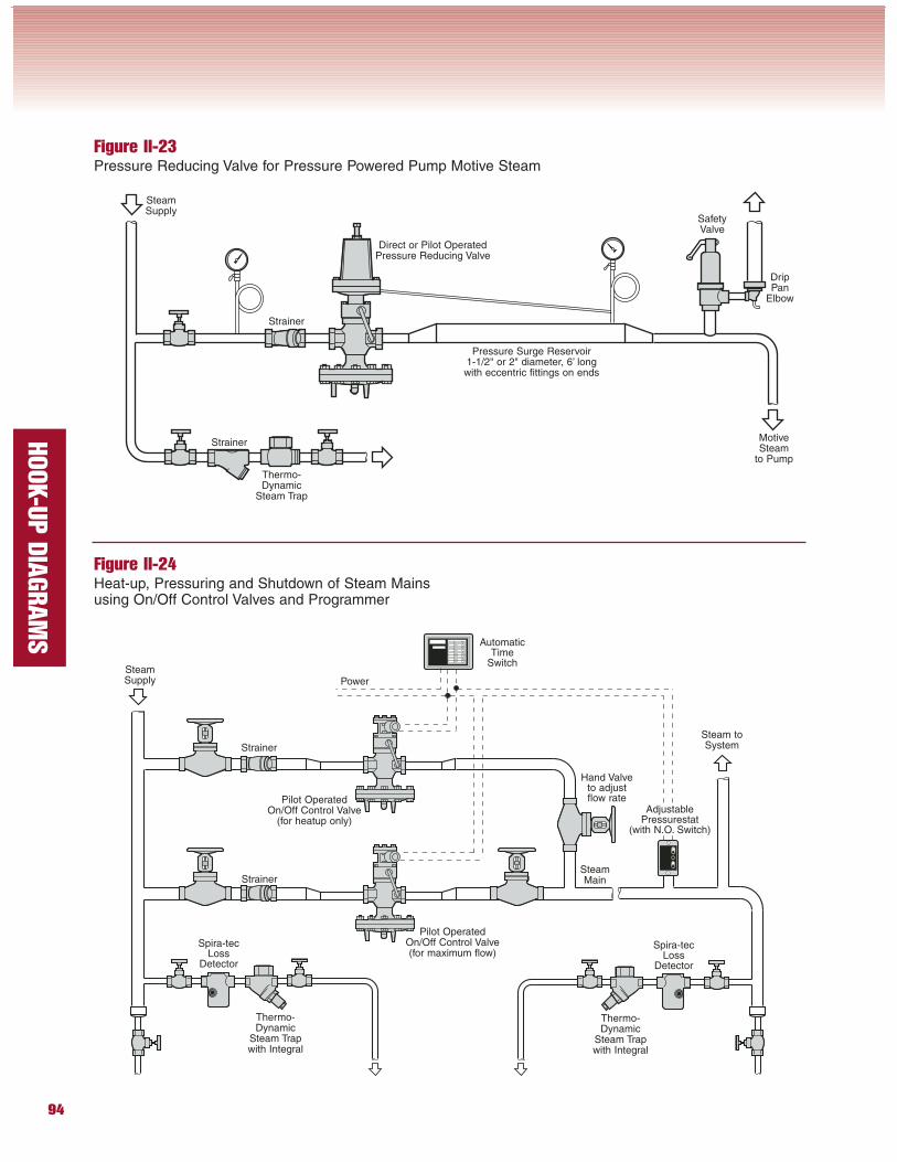
Figure II-23Pressure Reducing Valve for Pressure Powered Pump Motive Steam
Figure II-24Heat-up, Pressuring and Shutdown of Steam Mainsusing On/Off Control Valves and Programmer
Thermo-Dynamic
Steam Trapwith Integral
Pilot OperatedOn/Off Control Valve
(for heatup only)
Spira-tecLoss
Detector
Strainer
SteamSupply
Strainer
Thermo-Dynamic
Steam Trapwith Integral
Spira-tecLoss
Detector
Pilot OperatedOn/Off Control Valve(for maximum flow)
SteamMain
AutomaticTime
Switch
Power
Thermo-Dynamic
Steam Trap
SteamSupply
Strainer
Strainer
SafetyValve
DripPan
Elbow
MotiveSteam
to Pump
Direct or Pilot OperatedPressure Reducing Valve
Pressure Surge Reservoir1-1/2" or 2" diameter, 6’ longwith eccentric fittings on ends
Steam toSystem
Hand Valveto adjustflow rate
AdjustablePressurestat
(with N.O. Switch)
95
HOOK-U
P D
IAGRAM
S
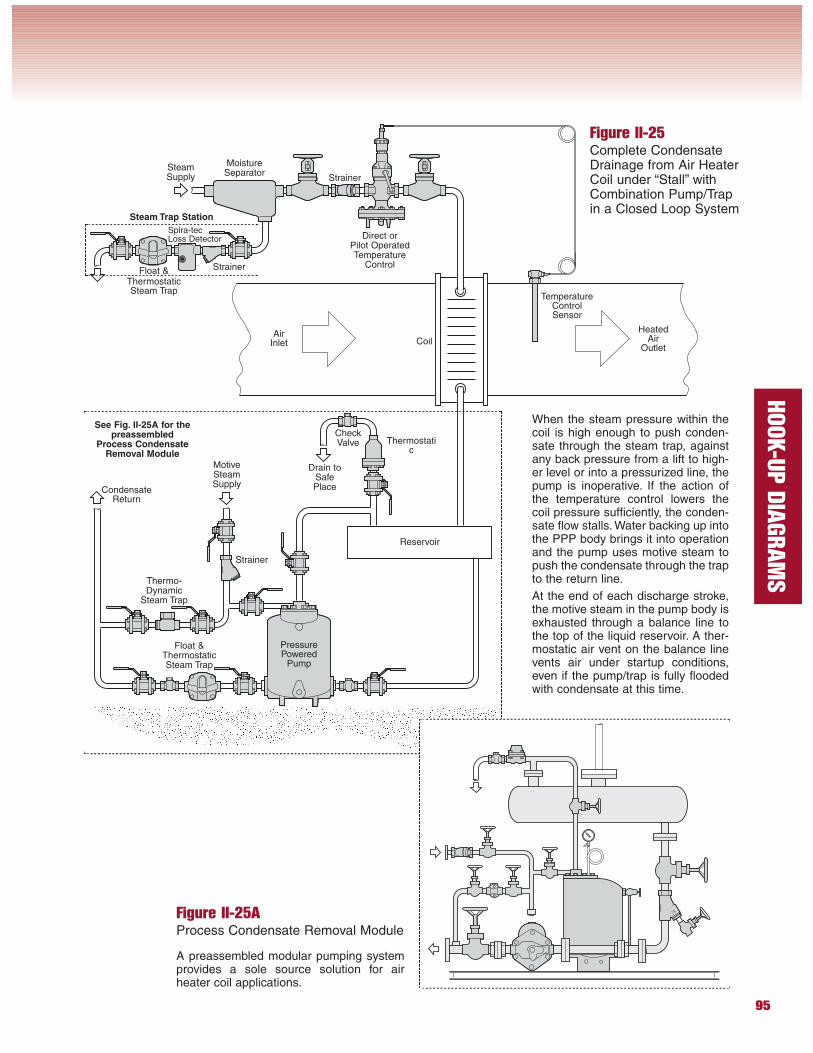
Figure II-25Complete CondensateDrainage from Air HeaterCoil under “Stall” withCombination Pump/Trapin a Closed Loop System
When the steam pressure within thecoil is high enough to push conden-sate through the steam trap, againstany back pressure from a lift to high-er level or into a pressurized line, thepump is inoperative. If the action ofthe temperature control lowers thecoil pressure sufficiently, the conden-sate flow stalls. Water backing up intothe PPP body brings it into operationand the pump uses motive steam topush the condensate through the trapto the return line.
At the end of each discharge stroke,the motive steam in the pump body isexhausted through a balance line tothe top of the liquid reservoir. A ther-mostatic air vent on the balance linevents air under startup conditions,even if the pump/trap is fully floodedwith condensate at this time.
Figure II-25AProcess Condensate Removal Module
A preassembled modular pumping systemprovides a sole source solution for airheater coil applications.
Float &ThermostaticSteam Trap
Direct orPilot OperatedTemperature
Control
Strainer
SteamSupply
MotiveSteamSupply
PressurePowered
Pump
MoistureSeparator
Thermo-Dynamic
Steam Trap
Reservoir
CondensateReturn
HeatedAir
Outlet
TemperatureControlSensor
Thermostatic
AirInlet
CheckValve
Float &ThermostaticSteam Trap
Strainer
Spira-tecLoss Detector
Strainer
Coil
Drain toSafePlace
See Fig. II-25A for thepreassembled
Process CondensateRemoval Module
Steam Trap Station
96
HOOK-U
P D
IAGRAM
S
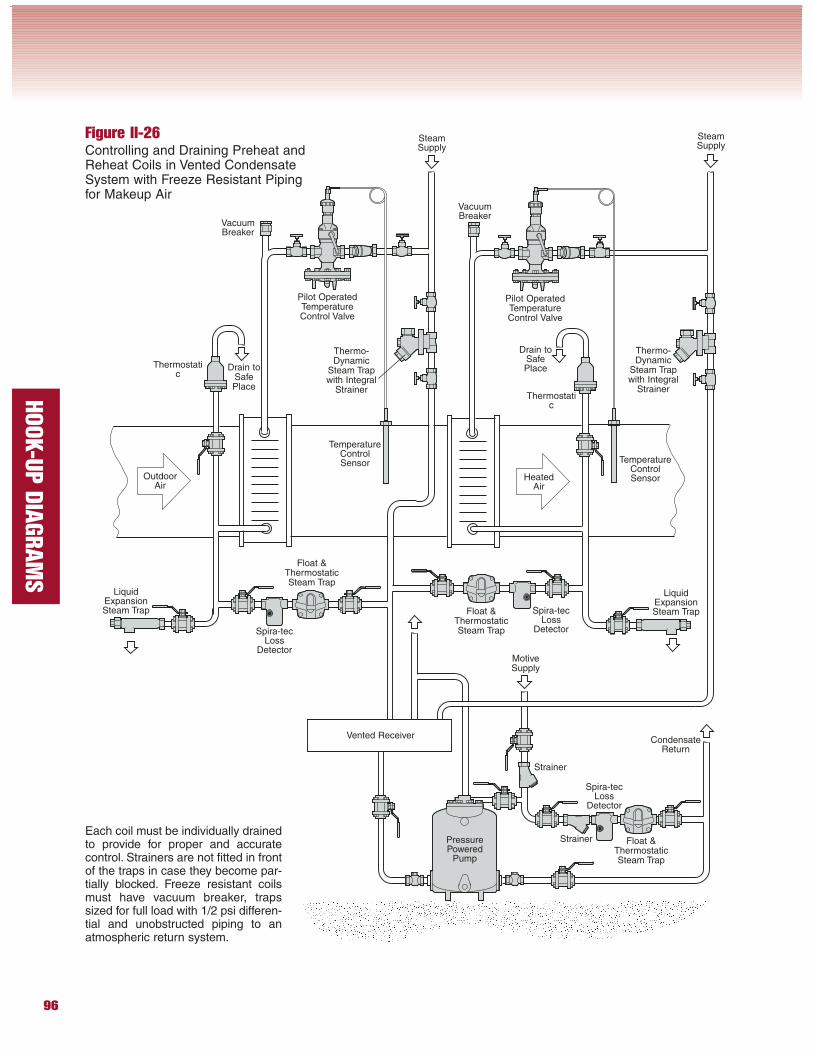
Figure II-26Controlling and Draining Preheat andReheat Coils in Vented CondensateSystem with Freeze Resistant Pipingfor Makeup Air
Each coil must be individually drainedto provide for proper and accuratecontrol. Strainers are not fitted in frontof the traps in case they become par-tially blocked. Freeze resistant coilsmust have vacuum breaker, trapssized for full load with 1/2 psi differen-tial and unobstructed piping to anatmospheric return system.
Float &ThermostaticSteam Trap
Pilot OperatedTemperatureControl Valve
Spira-tecLoss
DetectorMotiveSupply
PressurePowered
Pump
Thermo-Dynamic
Steam Trapwith Integral
Strainer
Vented ReceiverCondensate
Return
TemperatureControlSensor
Thermostatic
Pilot OperatedTemperatureControl Valve
Thermostatic
Float &ThermostaticSteam Trap
Spira-tecLoss
Detector
Strainer
Float &ThermostaticSteam Trap
Strainer
Spira-tecLoss
Detector
TemperatureControlSensorHeated
AirOutdoor
Air
VacuumBreaker
SteamSupply
SteamSupply
Thermo-Dynamic
Steam Trapwith Integral
Strainer
VacuumBreaker
LiquidExpansionSteam Trap
LiquidExpansionSteam Trap
Drain toSafePlaceDrain to
SafePlace
97
HOOK-U
P D
IAGRAM
S
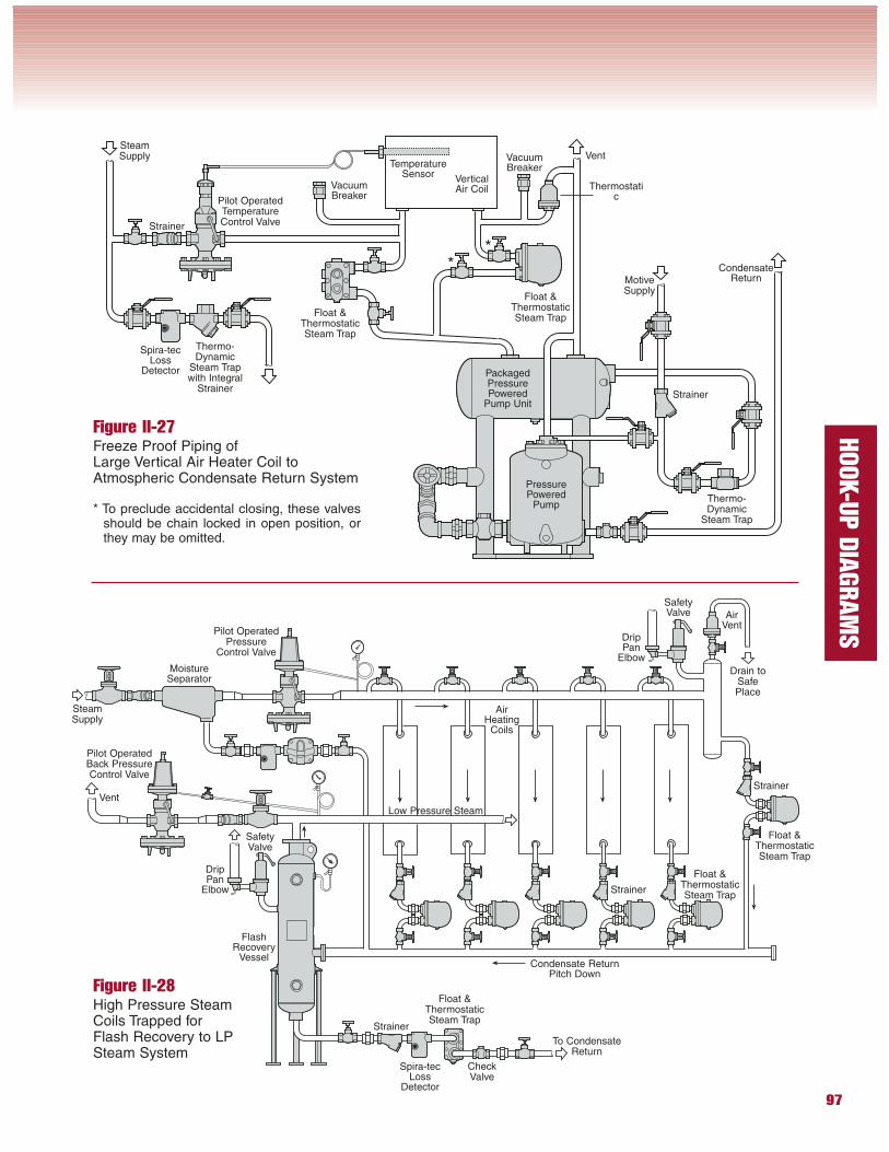
Figure II-27Freeze Proof Piping ofLarge Vertical Air Heater Coil toAtmospheric Condensate Return System
* To preclude accidental closing, these valvesshould be chain locked in open position, orthey may be omitted.
Figure II-28High Pressure SteamCoils Trapped forFlash Recovery to LPSteam System
Float &ThermostaticSteam Trap
Pilot OperatedTemperatureControl Valve
MotiveSupply
PressurePowered
Pump
Thermo-Dynamic
Steam Trapwith Integral
Strainer
CondensateReturn
TemperatureSensor
Thermostatic
Float &ThermostaticSteam Trap
Strainer
Float &ThermostaticSteam Trap
Strainer
Spira-tecLoss
Detector
Thermo-Dynamic
Steam Trap
PackagedPressurePowered
Pump Unit
Strainer
Spira-tecLoss
Detector
VerticalAir Coil
SteamSupply
Pilot OperatedBack PressureControl Valve
Condensate ReturnPitch Down
MoistureSeparator
Float &ThermostaticSteam Trap
Strainer
FlashRecovery
Vessel
Float &ThermostaticSteam Trap
Strainer
Pilot OperatedPressure
Control Valve
SafetyValve
SafetyValve
VacuumBreaker
VacuumBreaker
**
Vent
SteamSupply
Vent
DripPan
Elbow
CheckValve
To CondensateReturn
DripPan
Elbow
AirVent
AirHeating
Coils
Low Pressure Steam
Drain toSafePlace
98
HOOK-U
P D
IAGRAM
S
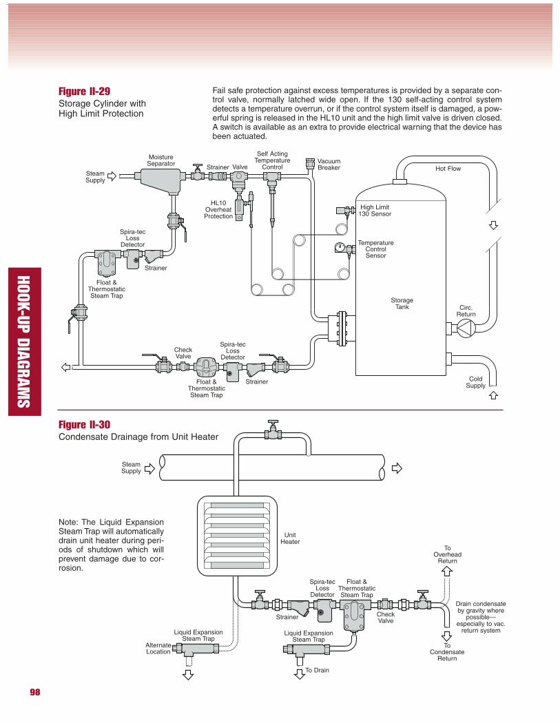
Figure II-29Storage Cylinder withHigh Limit Protection
Fail safe protection against excess temperatures is provided by a separate con-trol valve, normally latched wide open. If the 130 self-acting control systemdetects a temperature overrun, or if the control system itself is damaged, a pow-erful spring is released in the HL10 unit and the high limit valve is driven closed.A switch is available as an extra to provide electrical warning that the device hasbeen actuated.
Figure II-30Condensate Drainage from Unit Heater
TemperatureControlSensor
Spira-tecLoss
Detector
Valve
MoistureSeparator
Float &ThermostaticSteam Trap
Float &ThermostaticSteam Trap
Strainer
Self ActingTemperature
Control
Spira-tecLoss
Detector
Strainer
SteamSupply
Strainer
High Limit130 Sensor
HL10OverheatProtection
Hot Flow
Circ.Return
ColdSupply
StorageTank
Float &ThermostaticSteam Trap
Spira-tecLoss
Detector
Strainer
SteamSupply
UnitHeater
Drain condensateby gravity where
possible—especially to vac.
return system
VacuumBreaker
CheckValve
CheckValve
ToCondensate
Return
ToOverhead
Return
Liquid ExpansionSteam Trap
To Drain
AlternateLocation
Note: The Liquid ExpansionSteam Trap will automaticallydrain unit heater during peri-ods of shutdown which willprevent damage due to cor-rosion.
Liquid ExpansionSteam Trap
99
HOOK-U
P D
IAGRAM
S
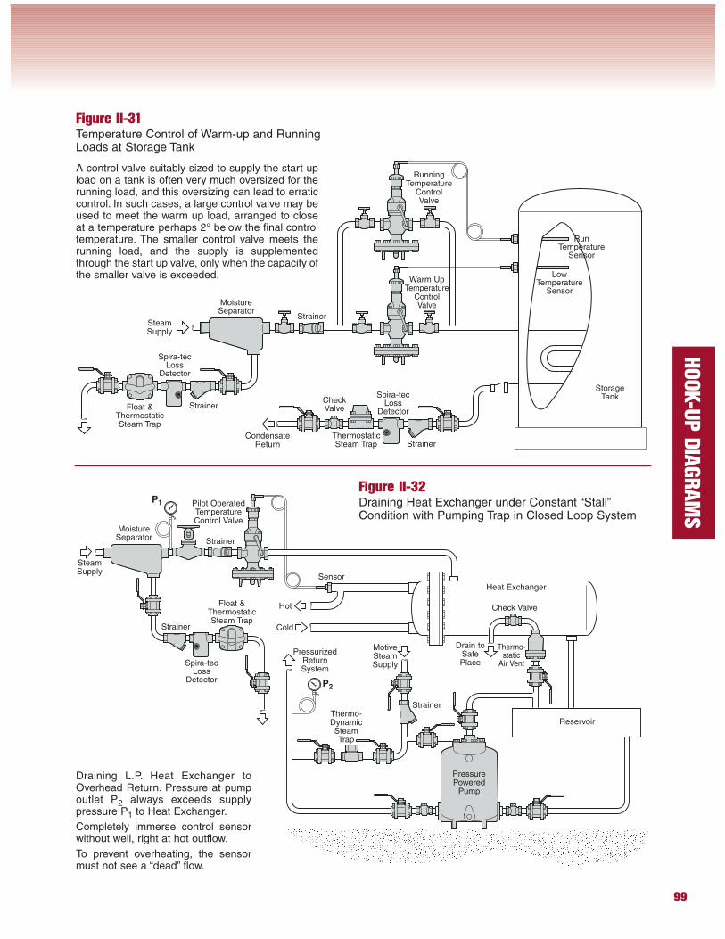
Figure II-31Temperature Control of Warm-up and RunningLoads at Storage Tank
Figure II-32Draining Heat Exchanger under Constant “Stall”Condition with Pumping Trap in Closed Loop System
A control valve suitably sized to supply the start upload on a tank is often very much oversized for therunning load, and this oversizing can lead to erraticcontrol. In such cases, a large control valve may beused to meet the warm up load, arranged to closeat a temperature perhaps 2° below the final controltemperature. The smaller control valve meets therunning load, and the supply is supplementedthrough the start up valve, only when the capacity ofthe smaller valve is exceeded.
Draining L.P. Heat Exchanger toOverhead Return. Pressure at pumpoutlet P2 always exceeds supplypressure P1 to Heat Exchanger.
Completely immerse control sensorwithout well, right at hot outflow.
To prevent overheating, the sensormust not see a “dead” flow.
LowTemperature
Sensor
Spira-tecLoss
Detector
MoistureSeparator
ThermostaticSteam Trap Strainer
RunningTemperature
ControlValve
StrainerSteamSupply
CondensateReturn
StorageTank
Spira-tecLoss
Detector
StrainerFloat &ThermostaticSteam Trap
Warm UpTemperature
ControlValve
RunTemperature
Sensor
Thermo-static
Air Vent
MoistureSeparator
Pilot OperatedTemperatureControl Valve
Strainer
SteamSupply
Heat Exchanger
Spira-tecLoss
Detector
Strainer
PressurePowered
Pump
Thermo-DynamicSteamTrap
Float &ThermostaticSteam Trap
Hot
Cold
MotiveSteamSupply
Reservoir
Sensor
PressurizedReturnSystem
CheckValve
Strainer
Check Valve
P1
P2
Drain toSafePlace
100
HOOK-U
P D
IAGRAM
S
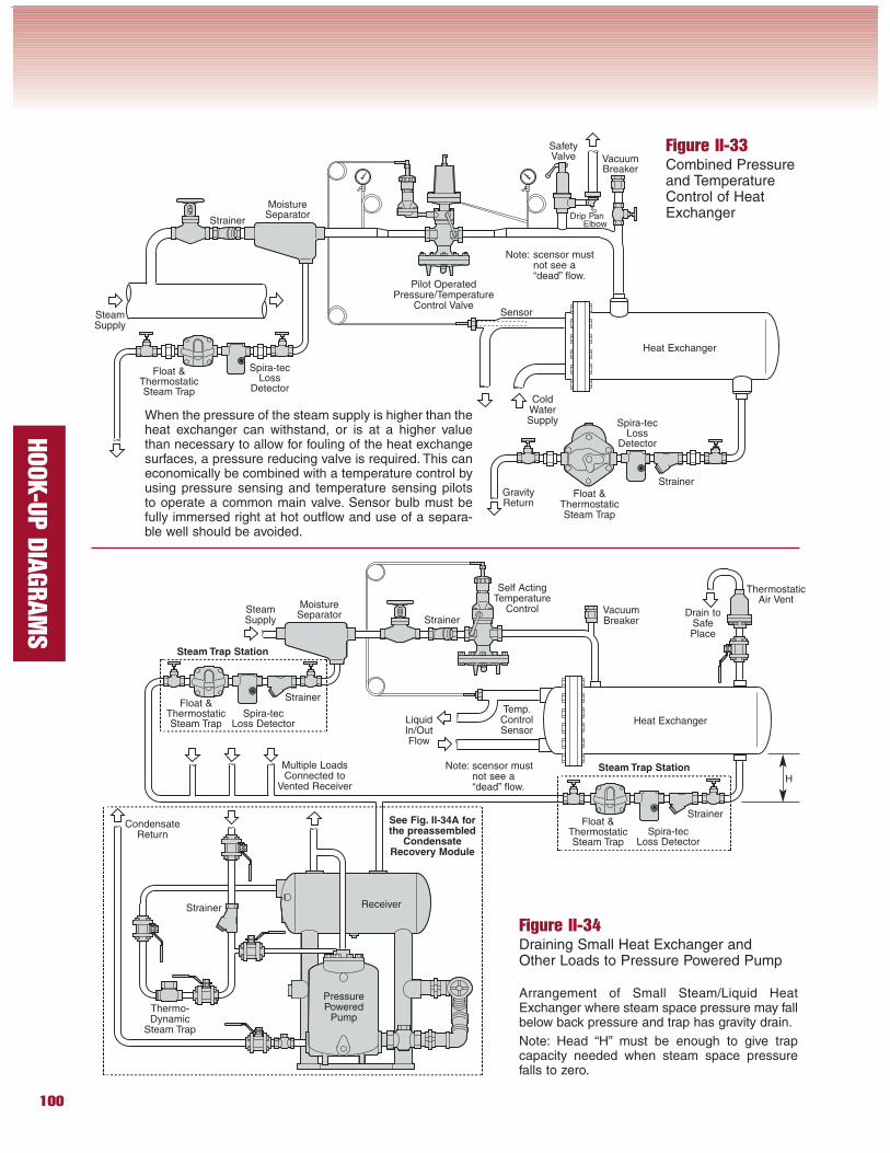
Figure II-33Combined Pressureand TemperatureControl of HeatExchanger
When the pressure of the steam supply is higher than theheat exchanger can withstand, or is at a higher valuethan necessary to allow for fouling of the heat exchangesurfaces, a pressure reducing valve is required. This caneconomically be combined with a temperature control byusing pressure sensing and temperature sensing pilotsto operate a common main valve. Sensor bulb must befully immersed right at hot outflow and use of a separa-ble well should be avoided.
Figure II-34Draining Small Heat Exchanger andOther Loads to Pressure Powered Pump
Arrangement of Small Steam/Liquid HeatExchanger where steam space pressure may fallbelow back pressure and trap has gravity drain.
Note: Head “H” must be enough to give trapcapacity needed when steam space pressurefalls to zero.
ThermostaticAir Vent
MoistureSeparator
Pilot OperatedPressure/Temperature
Control Valve
Heat Exchanger
Spira-tecLoss
Detector
StrainerFloat &
ThermostaticSteam Trap
ColdWaterSupply
Sensor
Spira-tecLoss
Detector
Float &ThermostaticSteam Trap
SafetyValve
Strainer
GravityReturn
SteamSupply
StrainerFloat &
ThermostaticSteam Trap
SteamSupply
Spira-tecLoss Detector
StrainerFloat &
ThermostaticSteam Trap
VacuumBreaker
Temp.ControlSensor
Self ActingTemperature
ControlMoistureSeparator
Heat Exchanger
PressurePowered
Pump
ReceiverStrainer
Thermo-Dynamic
Steam Trap
CondensateReturn
Multiple LoadsConnected to
Vented Receiver
Spira-tecLoss Detector
VacuumBreaker
Drip PanElbow
LiquidIn/OutFlow
Strainer
H
See Fig. II-34A forthe preassembled
CondensateRecovery Module
Drain toSafePlace
Steam Trap Station
Steam Trap Station
Note: scensor mustnot see a“dead” flow.
Note: scensor mustnot see a“dead” flow.
101
HOOK-U
P D
IAGRAM
S
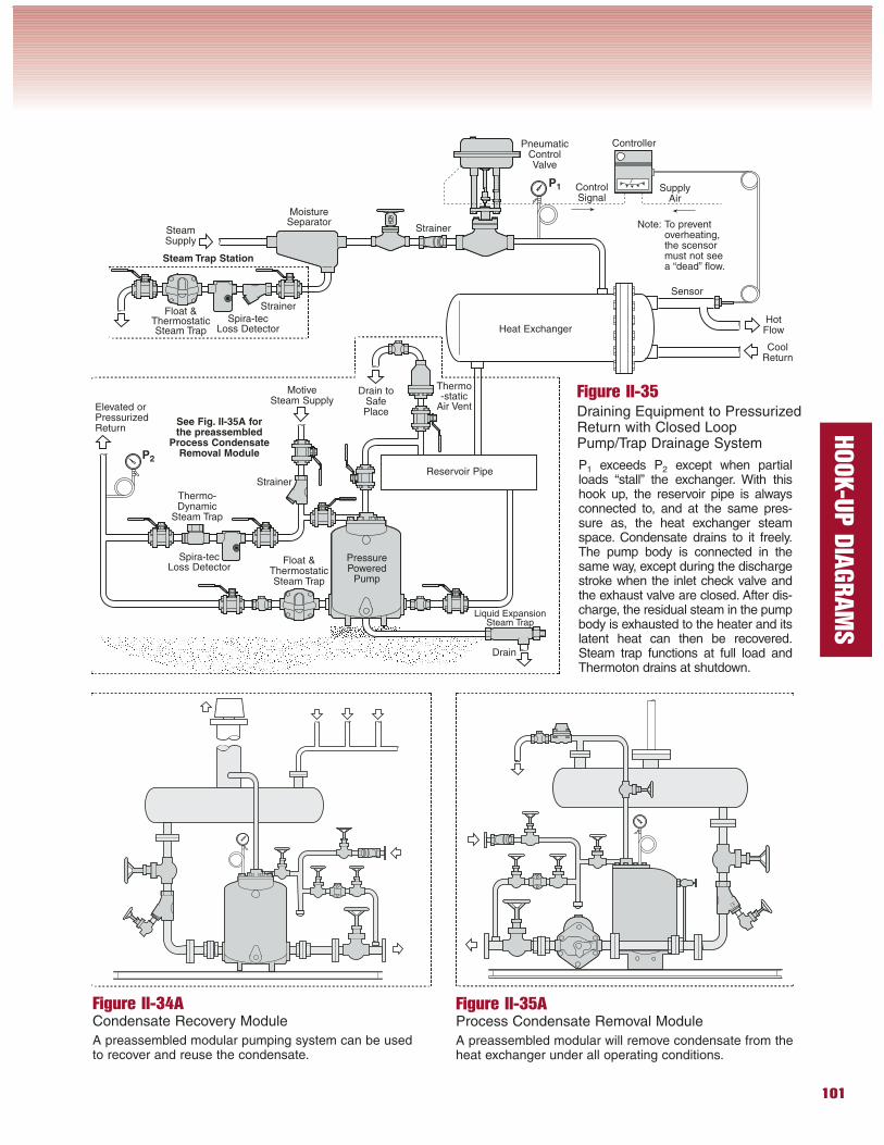
Figure II-35Draining Equipment to PressurizedReturn with Closed LoopPump/Trap Drainage System
P1 exceeds P2 except when partialloads “stall” the exchanger. With thishook up, the reservoir pipe is alwaysconnected to, and at the same pres-sure as, the heat exchanger steamspace. Condensate drains to it freely.The pump body is connected in thesame way, except during the dischargestroke when the inlet check valve andthe exhaust valve are closed. After dis-charge, the residual steam in the pumpbody is exhausted to the heater and itslatent heat can then be recovered.Steam trap functions at full load andThermoton drains at shutdown.
SteamSupply
Spira-tecLoss Detector
Strainer
Float &ThermostaticSteam Trap
PneumaticControlValve
MoistureSeparator
Heat Exchanger
PressurePowered
Pump
Reservoir Pipe
Drain
Thermo-Dynamic
Steam Trap
Elevated orPressurizedReturn
Strainer
Strainer
Spira-tecLoss Detector
Float &ThermostaticSteam Trap
HotFlow
CoolReturn
MotiveSteam Supply
Thermo-static
Air Vent
P1
P2
See Fig. II-35A forthe preassembled
Process CondensateRemoval Module
Figure II-35AProcess Condensate Removal Module
A preassembled modular will remove condensate from the heat exchanger under all operating conditions.
Figure II-34ACondensate Recovery Module
A preassembled modular pumping system can be usedto recover and reuse the condensate.
Sensor
Controller
SupplyAir
ControlSignal
Drain toSafePlace
Steam Trap Station
Liquid ExpansionSteam Trap
Note: To prevent overheating, the scensor must not seea “dead” flow.
102
HOOK-U
P D
IAGRAM
S
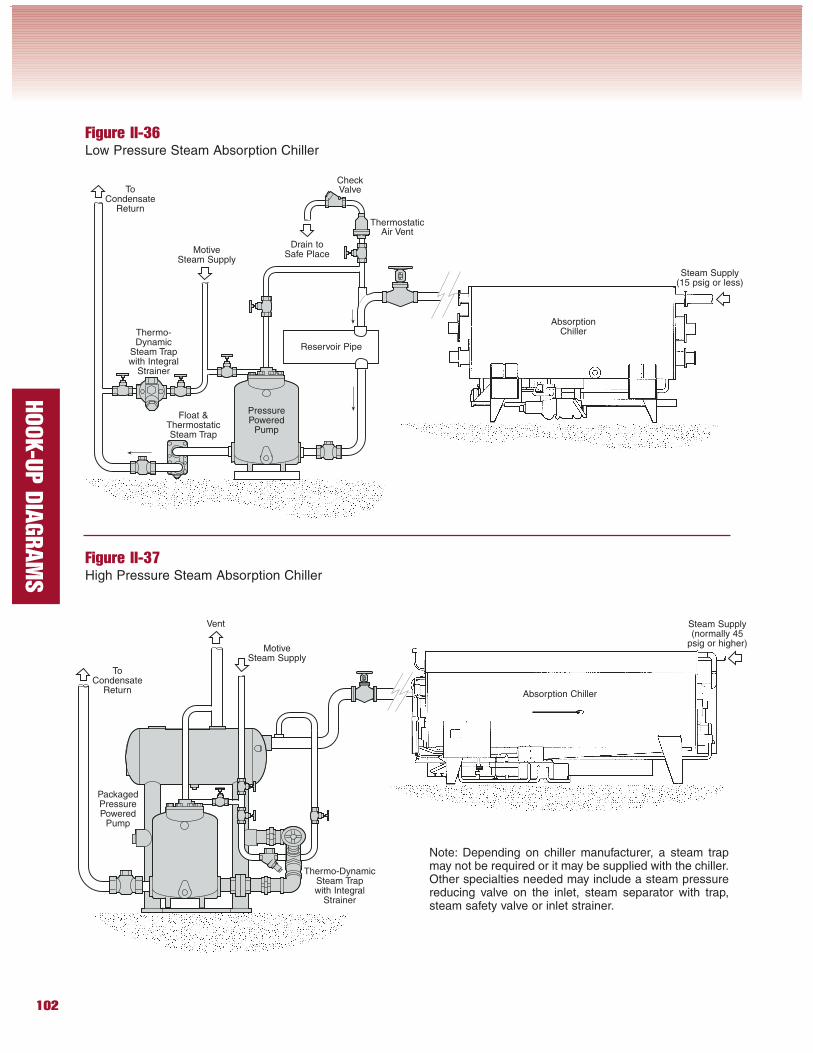
Figure II-36Low Pressure Steam Absorption Chiller
Figure II-37High Pressure Steam Absorption Chiller
Float &ThermostaticSteam Trap
PressurePowered
Pump
Reservoir Pipe
Thermo-Dynamic
Steam Trapwith Integral
Strainer
ToCondensate
Return
MotiveSteam Supply
ThermostaticAir Vent
CheckValve
AbsorptionChiller
Steam Supply(15 psig or less)
ToCondensate
Return
MotiveSteam Supply
Absorption Chiller
Steam Supply(normally 45
psig or higher)
Vent
PackagedPressurePowered
Pump
Thermo-DynamicSteam Trapwith Integral
Strainer
Note: Depending on chiller manufacturer, a steam trapmay not be required or it may be supplied with the chiller.Other specialties needed may include a steam pressurereducing valve on the inlet, steam separator with trap,steam safety valve or inlet strainer.
Drain toSafe Place
103
HOOK-U
P D
IAGRAM
S
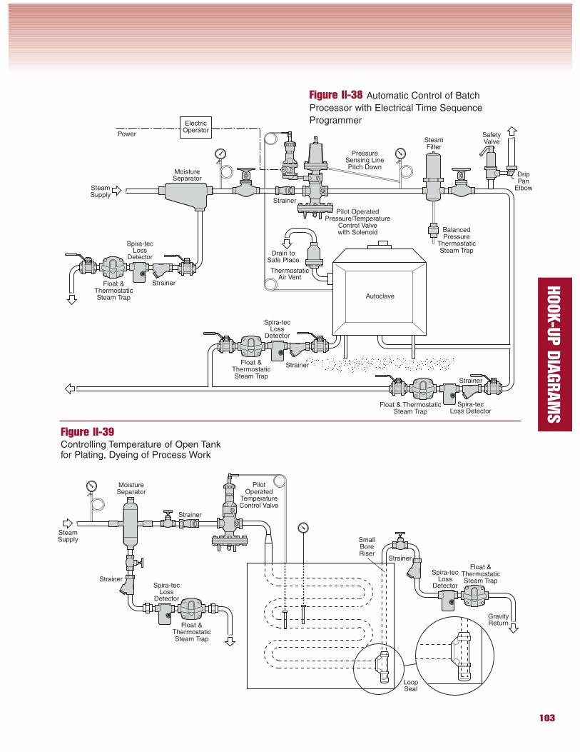
Figure II-38 Automatic Control of Batch
Processor with Electrical Time Sequence
Programmer
Figure II-39Controlling Temperature of Open Tankfor Plating, Dyeing of Process Work
ThermostaticAir Vent
SteamSupply
Spira-tecLoss Detector
Float &ThermostaticSteam Trap
Pilot OperatedPressure/Temperature
Control Valvewith Solenoid
MoistureSeparator
Autoclave
SafetyValve
Strainer
Strainer
Spira-tecLoss
Detector
Float &ThermostaticSteam Trap
ElectricOperator
Spira-tecLoss
Detector
Strainer
Float & ThermostaticSteam Trap
SteamFilter
Power
Strainer
Float &ThermostaticSteam Trap
Spira-tecLoss
DetectorStrainer
Float &ThermostaticSteam Trap
Spira-tecLoss
Detector
MoistureSeparator
Strainer
PressureSensing LinePitch Down
Strainer
PilotOperated
TemperatureControl Valve
LoopSeal
GravityReturn
DripPan
Elbow
BalancedPressure
ThermostaticSteam Trap
SteamSupply
Drain toSafe Place
SmallBoreRiser
104
HOOK-U
P D
IAGRAM
S
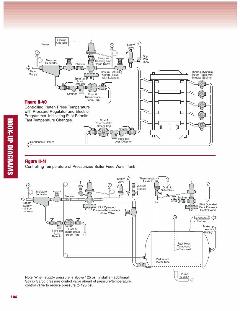
Figure II-40Controlling Platen Press Temperaturewith Pressure Regulator and ElectricProgrammer. Indicating Pilot PermitsFast Temperature Changes
Figure II-41Controlling Temperature of Pressurized Boiler Feed Water Tank
Note: When supply pressure is above 125 psi, install an additionalSpirax Sarco pressure control valve ahead of pressure/temperaturecontrol valve to reduce pressure to 125 psi.
Strainer
Thermo-DynamicSteam Traps withIntegral Strainer
Spira-tecLoss Detector
Strainer
Float &ThermostaticSteam Trap
Spira-tecLoss
Detector
Strainer
Pressure ReducingControl Valvewith Solenoid
SteamSupply
MoistureSeparator
SafetyValve
ElectricOperator
Power
PressureSensing LinePitch Down
Float &ThermostaticSteam Trap
Condensate Return
Strainer
Spira-tecLoss
Detector
Strainer
Pilot OperatedPressure/Temperature
Control Valve
SteamSupply(125 psior less)
MoistureSeparator
SafetyValve
Float &ThermostaticSteam Trap
VacuumBreaker
Pilot OperatedBack PressureControl Valve
PerforatedHeater Tube
Pack HeatCompoundin Bulb Well
Make upWaterSupply
PumpSuction
CondensateReturn
ThermostaticAir Vent
DripPan
Elbow
Drain toSafe Place
105
HOOK-U
P D
IAGRAM
S
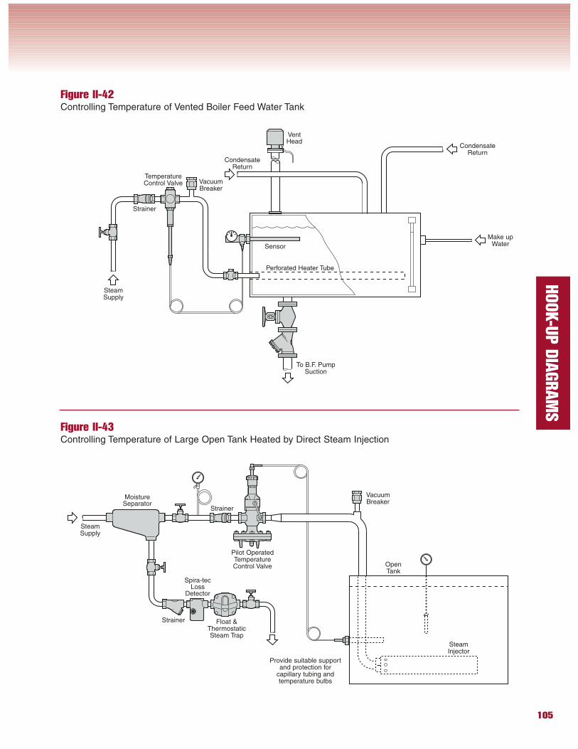
Figure II-42Controlling Temperature of Vented Boiler Feed Water Tank
Figure II-43Controlling Temperature of Large Open Tank Heated by Direct Steam Injection
Strainer
Spira-tecLoss
Detector
Strainer
Pilot OperatedTemperatureControl Valve
MoistureSeparator
Float &ThermostaticSteam Trap
VacuumBreaker
SteamInjector
SteamSupply
OpenTank
Provide suitable supportand protection for
capillary tubing andtemperature bulbs
VacuumBreaker
Strainer
CondensateReturn
VentHead
SteamSupply
TemperatureControl Valve
Sensor
To B.F. PumpSuction
Perforated Heater Tube
Make upWater
CondensateReturn
106
HOOK-U
P D
IAGRAM
S
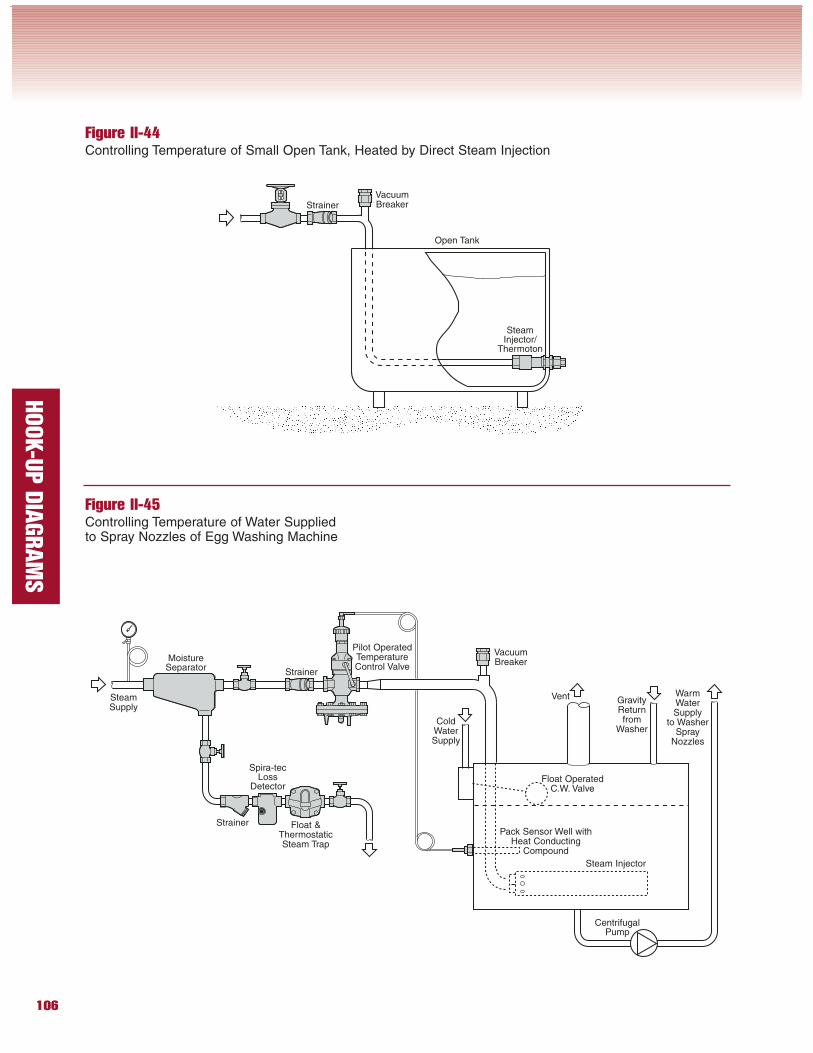
Figure II-44Controlling Temperature of Small Open Tank, Heated by Direct Steam Injection
Figure II-45Controlling Temperature of Water Suppliedto Spray Nozzles of Egg Washing Machine
Strainer
SteamInjector/
Thermoton
VacuumBreaker
Strainer
Spira-tecLoss
Detector
Strainer
Pilot OperatedTemperatureControl Valve
SteamSupply
MoistureSeparator
ColdWaterSupply
Float &ThermostaticSteam Trap
VacuumBreaker
Pack Sensor Well withHeat Conducting
Compound
Steam Injector
CentrifugalPump
Float OperatedC.W. Valve
WarmWaterSupply
to WasherSpray
Nozzles
GravityReturnfrom
Washer
Open Tank
Vent
107
HOOK-U
P D
IAGRAM
S
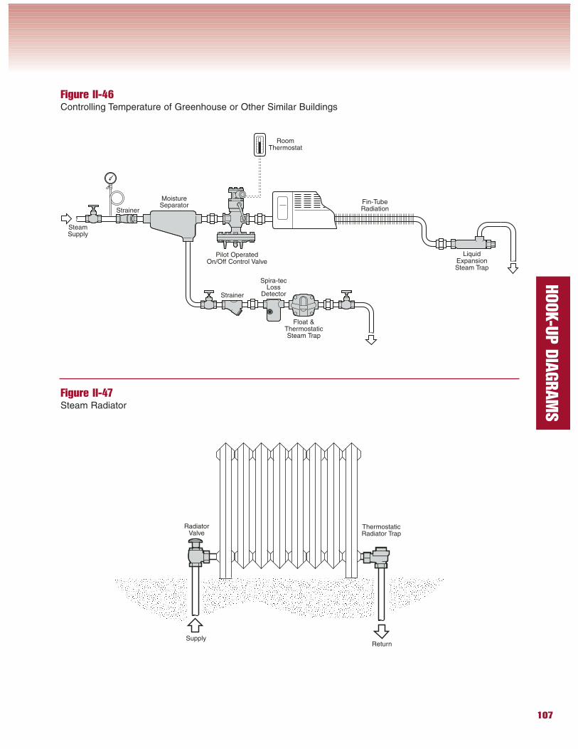
Figure II-46Controlling Temperature of Greenhouse or Other Similar Buildings
Figure II-47Steam Radiator
Strainer
Spira-tecLoss
DetectorStrainer
Fin-TubeRadiation
SteamSupply
MoistureSeparator
Float &ThermostaticSteam Trap
RoomThermostat
LiquidExpansionSteam Trap
Pilot OperatedOn/Off Control Valve
Return
ThermostaticRadiator Trap
RadiatorValve
Supply
108
HOOK-U
P D
IAGRAM
S
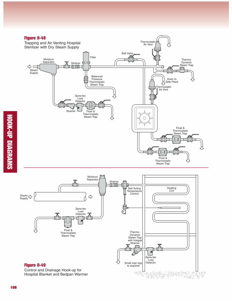
Figure II-48Trapping and Air Venting HospitalSterilizer with Dry Steam Supply
Figure II-49Control and Drainage Hook-up forHospital Blanket and Bedpan Warmer
Strainer
Spira-tecLoss
Detector
Strainer
SteamSupply
MoistureSeparator
Float &ThermostaticSteam Trap
ThermostaticAir Vent
Float &ThermostaticSteam Trap
Float &ThermostaticSteam Trap
ThermostaticAir Vent
Ball Valve
Thermo-Dynamic
Steam Trap
Filter
Spira-tecLoss
Detector
Strainer
Float &ThermostaticSteam Trap
Thermo-Dynamic
Steam Trapwith Integral
Strainer
MoistureSeparator
BalancedPressure
ThermostaticSteam Trap
Spira-tecLoss
Detector
Self ActingTemperature
Control
HeatingCoil
Small size trapis required
Drain toSafe Place
SteamSupply
109
HOOK-U
P D
IAGRAM
S
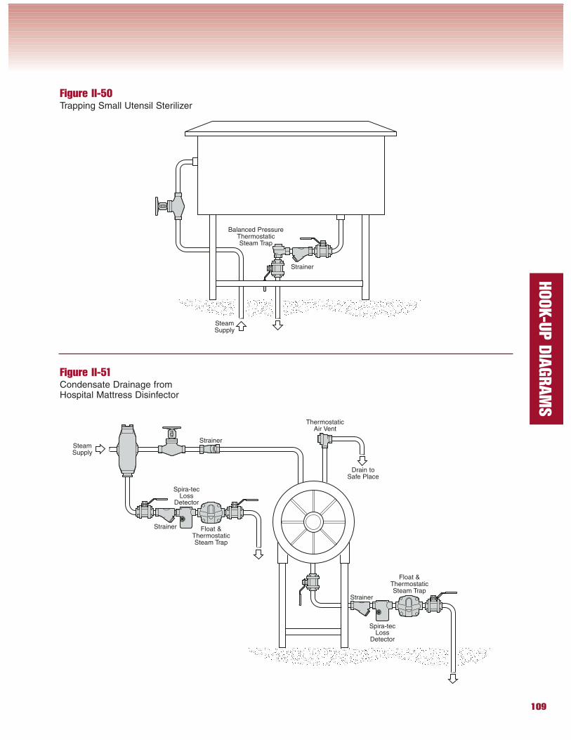
Figure II-50Trapping Small Utensil Sterilizer
Figure II-51Condensate Drainage fromHospital Mattress Disinfector
Strainer
SteamSupply
Balanced PressureThermostaticSteam Trap
Strainer
SteamSupply
Float &ThermostaticSteam Trap
Spira-tecLoss
Detector
Spira-tecLoss
Detector
Strainer Float &ThermostaticSteam Trap
ThermostaticAir Vent
Strainer
Drain toSafe Place
110
HOOK-U
P D
IAGRAM
S
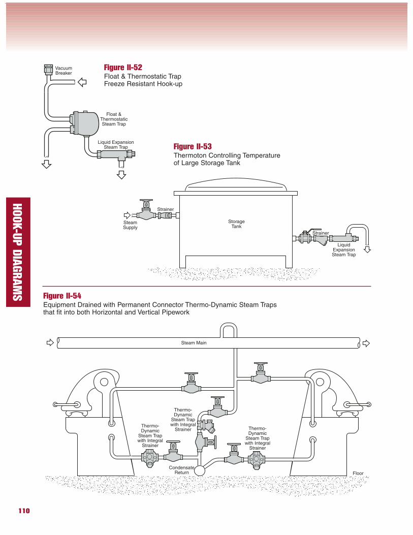
Figure II-52Float & Thermostatic TrapFreeze Resistant Hook-up
Float &ThermostaticSteam Trap
Liquid ExpansionSteam Trap
VacuumBreaker
Figure II-53Thermoton Controlling Temperatureof Large Storage Tank
LiquidExpansionSteam Trap
SteamSupply
Strainer
Strainer
Figure II-54Equipment Drained with Permanent Connector Thermo-Dynamic Steam Trapsthat fit into both Horizontal and Vertical Pipework
Floor
Thermo-Dynamic
Steam Trapwith Integral
Strainer
Thermo-Dynamic
Steam Trapwith Integral
StrainerThermo-Dynamic
Steam Trapwith Integral
Strainer
CondensateReturn
Steam Main
StorageTank
111
HOOK-U
P D
IAGRAM
S
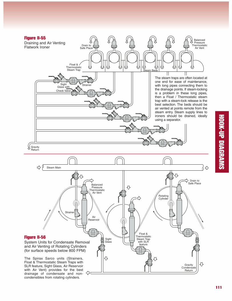
Figure II-55Draining and Air VentingFlatwork Ironer
The steam traps are often located atone end for ease of maintenance,with long pipes connecting them tothe drainage points. If steam-lockingis a problem in these long pipes,then a Float / Thermostatic steamtrap with a steam-lock release is thebest selection. The beds should beair vented at points remote from thesteam entry. Steam supply lines toironers should be drained, ideallyusing a separator.
Figure II-56System Units for Condensate Removaland Air Venting of Rotating Cylinders(for surface speeds below 800 FPM)
GravityReturn
StrainerSightGlass with
Check Valve
Steam Beds
BalancedPressure
ThermostaticAir Vent
Strainer
BalancedPressure
ThermostaticAir Vent
Float &ThermostaticSteam Trapwith SLRfeature
SightGlass
GravityCondensate
Return
AirReservoir
Steam Main
RotatingCylinder
Drain toSafe Place
Float &ThermostaticSteam Trap
Drain toSafe Place
The Spirax Sarco units (Strainers,Float & Thermostatic Steam Traps withSLR feature, Sight Glass, Air Reservoirwith Air Vent) provides for the bestdrainage of condensate and non-condensibles from rotating cylinders.
112
HOOK-U
P D
IAGRAM
S
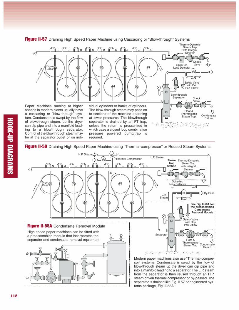
Figure II-57 Draining High Speed Paper Machine using Cascading or “Blow-through” Systems
Paper Machines running at higherspeeds in modern plants usually havea cascading or “blow-through” sys-tem. Condensate is swept by the flowof blowthrough steam, up the dryercan dip pipe and into a manifold lead-ing to a blowthrough separator.Control of the blowthrough steam maybe at the separator outlet or on indi-
vidual cylinders or banks of cylinders.The blow-through steam may pass onto sections of the machine operatingat lower pressures. The blowthroughseparator is drained by an FT trap,unless the return is pressurized inwhich case a closed loop combinationpressure powered pump/trap isrequired.
Figure II-58 Draining High Speed Paper Machine using “Thermal-compressor” or Reused Steam Systems
Thermo-DynamicSteam Trapwith Integral
Strainer
Spira-tecLoss Detector
Float &ThermostaticSteam Trap
Thermo-DynamicSteam Trapwith Integral
Strainer
Spira-tecLoss Detector
Safety Valvewith Drip
Pan Elbow
Float &ThermostaticSteam Trap
Safety Valvewith Drip
Pan Elbow
Separator
Blow throughSeparator
CondensateReturn
CondensateReturn
DryerCans
CheckValve
CheckValve
L.P. SteamH.P. Steam
Thermal Compressor
L.P.Steam
By-Pass
Modern paper machines also use “Thermal-compre-sor” systems. Condensate is swept by the flow ofblow-through steam up the dryer can dip pipe andinto a manifold leading to a separator.The L.P. steamfrom the separator is then reused through an H.P.steam driven thermal compressor or by-passed. Theseparator is drained like Fig. II-57 or engineered sys-tems package, Fig. II-58A.
Figure II-58A Condensate Removal Module
High speed paper machines can be fitted witha preassembled module that incorporates theseparator and condensate removal equipment.
DryerCans
SteamTrap
Station
See Fig. II-58A forthe preassembled
CondensateRemoval Module
113
HOOK-U
P D
IAGRAM
S
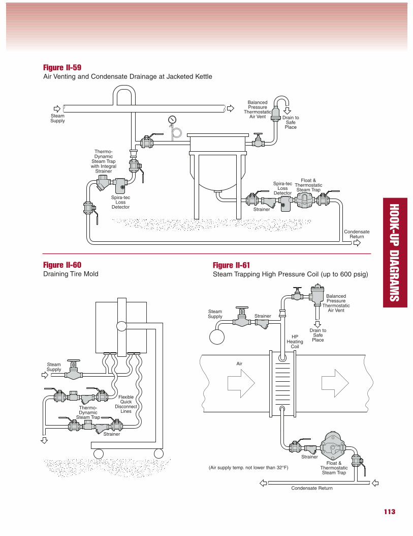
Figure II-59Air Venting and Condensate Drainage at Jacketed Kettle
Figure II-60Draining Tire Mold
Figure II-61Steam Trapping High Pressure Coil (up to 600 psig)
Float &ThermostaticSteam Trap
Strainer
BalancedPressure
ThermostaticAir VentSteam
Supply
Thermo-Dynamic
Steam Trapwith Integral
Strainer
Spira-tecLoss
Detector
Spira-tecLoss
Detector
CondensateReturn
Float &ThermostaticSteam Trap
Strainer
BalancedPressure
ThermostaticAir Vent
Strainer
HPHeating
Coil
Condensate Return
Air
SteamSupply
(Air supply temp. not lower than 32°F)
Strainer
Thermo-Dynamic
Steam Trap
SteamSupply
FlexibleQuick
DisconnectLines
Drain toSafePlace
Drain toSafePlace
114
HOOK-U
P D
IAGRAM
S
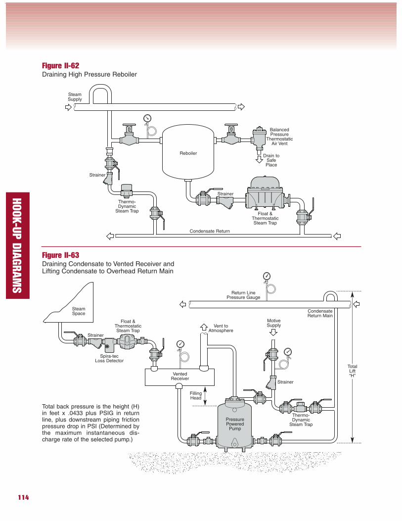
Figure II-62Draining High Pressure Reboiler
Figure II-63Draining Condensate to Vented Receiver andLifting Condensate to Overhead Return Main
Reboiler
Float &ThermostaticSteam Trap
Strainer
BalancedPressure
ThermostaticAir Vent
Strainer
Condensate Return
SteamSupply
Total back pressure is the height (H)in feet x .0433 plus PSIG in returnline, plus downstream piping frictionpressure drop in PSI (Determined bythe maximum instantaneous dis-charge rate of the selected pump.)
Drain toSafePlace
Thermo-Dynamic
Steam Trap
Float &ThermostaticSteam Trap
Strainer
Spira-tecLoss Detector
Thermo-Dynamic
Steam Trap
VentedReceiver
Return LinePressure Gauge
CondensateReturn Main
MotiveSupply
Strainer
SteamSpace
PressurePowered
Pump
Vent toAtmosphere
FillingHead
TotalLift“H”
115
HOOK-U
P D
IAGRAM
S
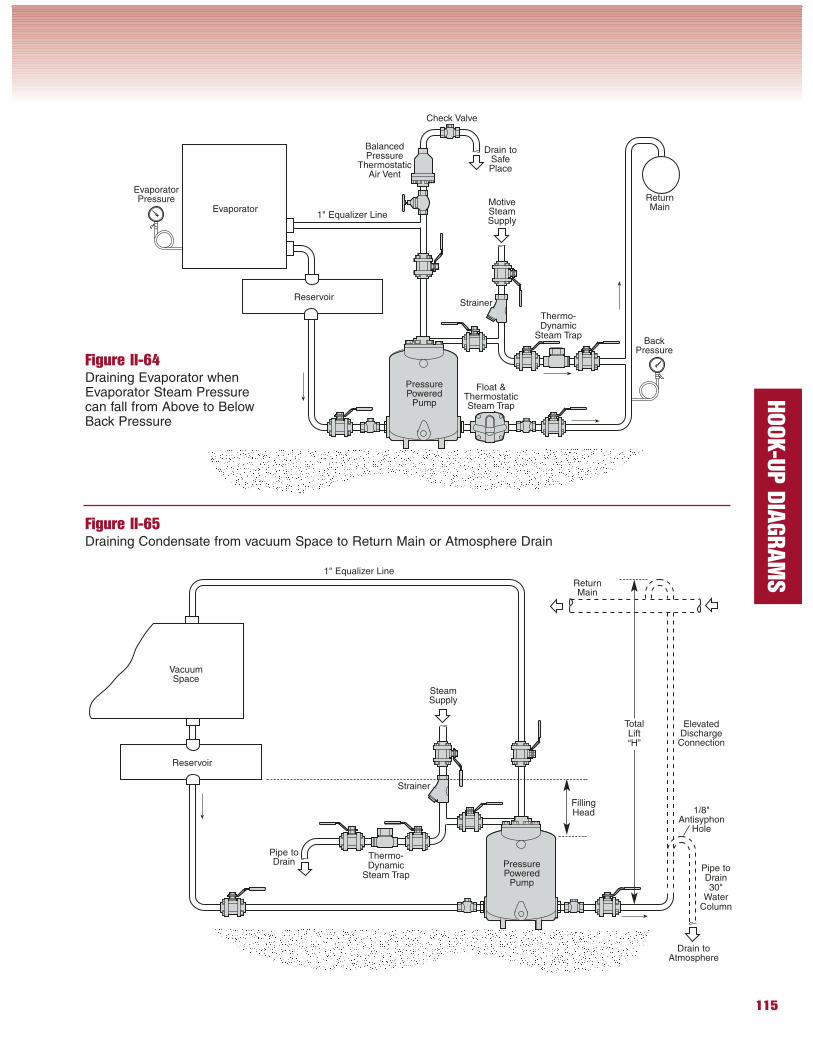
Figure II-64Draining Evaporator whenEvaporator Steam Pressurecan fall from Above to BelowBack Pressure
Figure II-65Draining Condensate from vacuum Space to Return Main or Atmosphere Drain
Evaporator
ReservoirStrainer
ReturnMain
BalancedPressure
ThermostaticAir Vent
Thermo-Dynamic
Steam Trap
PressurePowered
Pump
1" Equalizer Line
Float &ThermostaticSteam Trap
MotiveSteamSupply
VacuumSpace
Reservoir
Strainer
ReturnMain
Thermo-Dynamic
Steam TrapPressurePowered
Pump
SteamSupply
Pipe toDrain
Pipe toDrain30"
WaterColumn
TotalLift“H”
FillingHead
1" Equalizer Line
ElevatedDischarge
Connection
1/8"Antisyphon
Hole
Drain toSafePlace
Check Valve
BackPressure
EvaporatorPressure
Drain toAtmosphere
116
HOOK-U
P D
IAGRAM
S
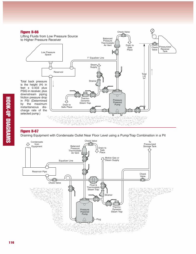
Figure II-66Lifting Fluids from Low Pressure Sourceto Higher Pressure Receiver
Figure II-67Draining Equipment with Condensate Outlet Near Floor Level using a Pump/Trap Combination in a Pit
Reservoir
Strainer
BalancedPressure
ThermostaticAir Vent
SteamSupply
Low PressureSpace
Thermo-Dynamic
Steam Trap
PressurePowered
Pump
PressurizedReceiver
Tank
Reservoir Pipe
Strainer
BalancedPressure
ThermostaticAir Vent
Motive Gas orSteam Supply
Thermo-Dynamic
Steam TrapPressurePowered
Pump
Float &ThermostaticSteam Trap
Equalizer Line
1" Equalizer Line
Total back pressureis the height (H) infeet x 0.433 plusPSIG in receiver, plusdownstream pipingfriction pressure dropin PSI (Determinedby the maximuminstantaneous dis-charge rate of theselected pump.)
Drain toSafePlace
Drain toSafe Place
Check Valve
CheckValve
TotalLift“H”
CheckValve
Check Valve
Check Valve
Drain toSafePlace
ToPressurized
Storage Tank
Plug
Condensatefrom
Equipment
117
HOOK-U
P D
IAGRAM
S
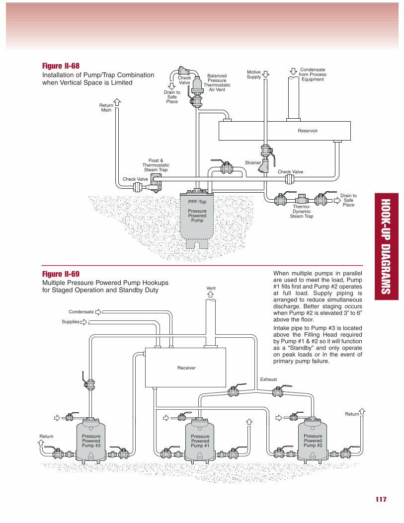
When multiple pumps in parallelare used to meet the load, Pump#1 fills first and Pump #2 operatesat full load. Supply piping isarranged to reduce simultaneousdischarge. Better staging occurswhen Pump #2 is elevated 3” to 6”above the floor.
Intake pipe to Pump #3 is locatedabove the Filling Head requiredby Pump #1 & #2 so it will functionas a “Standby” and only operateon peak loads or in the event ofprimary pump failure.
Figure II-68Installation of Pump/Trap Combinationwhen Vertical Space is Limited
Figure II-69Multiple Pressure Powered Pump Hookupsfor Staged Operation and Standby Duty
PressurePoweredPump #3
PressurePoweredPump #1
PressurePoweredPump #2
Receiver
Condensate
Supplies
Vent
Return
Return
Exhaust
PPF-Top
PressurePowered
Pump
Reservoir
Strainer
BalancedPressure
ThermostaticAir Vent
Thermo-Dynamic
Steam Trap
ReturnMain
Float &ThermostaticSteam Trap
Drain toSafePlace
Check Valve
Check Valve
MotiveSupply
Drain toSafePlace
CheckValve
Condensatefrom Process
Equipment
118
HOOK-U
P D
IAGRAM
S
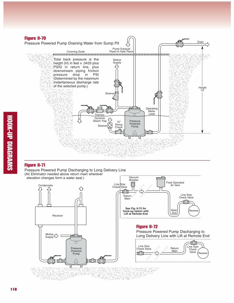
Figure II-70Pressure Powered Pump Draining Water from Sump Pit
Figure II-71Pressure Powered Pump Discharging to Long Delivery Line(Air Eliminator needed above return main wherever
elevation changes form a water seal.)
Total back pressure is theheight (H) in feet x .0433 plusPSIG in return line, plusdownstream piping frictionpressure drop in PSI(Determined by the maximuminstantaneous discharge rateof the selected pump.)
ReturnMain
PressurePowered
Pump
Receiver
PressurePowered
Pump
Condensate
VacuumBreaker
Float OperatedAir Vent
ReceiverWaterSeal
Strainer
Thermo-Dynamic
Steam Trap
Pump ExhaustPiped to Safe Place
MotiveSupply
Drain
OperatingWaterLevel
15°SwingCheck
Figure II-72Pressure Powered Pump Discharging toLong Delivery Line with Lift at Remote End
See Fig. II-72 forhook-up option withLift at Remote End
Receiver
ReturnMain
Line SizeCheck Valve
Height“H”
Covering Grate
Line SizeCheck Valve
Line SizeCheck Valve
Line SizeCheckValve
Strainer
MotiveSupply
119
HOOK-U
P D
IAGRAM
S
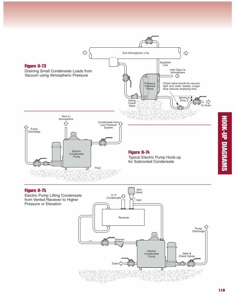
Figure II-73Draining Small Condensate Loads fromVacuum using Atmospheric Pressure
Figure II-74Typical Electric Pump Hook-upfor Subcooled Condensate
Figure II-75Electric Pump Lifting Condensatefrom Vented Receiver to HigherPressure or Elevation
Vent toAtmosphere
PumpDischarge
Condensate fromLow Pressure
System
Floor
PressurePowered
Pump
Inlet Open toAtmosphere
Check valve should be vacuumtight and water sealed. Largerdrop reduces emptying time.
Sub Atmospheric Line
EqualizerLine
To Drain
SwingCheckValve
MinimumDrop 3"
Receiver
ElectricCondensate
Pump
ElectricCondensate
Pump
Strainer
PumpDischarge
Vent
H. P.Condensate
Drain
Gate &Check Valves
VentHead
120
HOOK-U
P D
IAGRAM
S
Figure II-76Typical Flash SteamRecovery Hook-up
Figure II-77Flash Steam Recovery with Live Steam Make upand Back Pressure Surplussing Valves
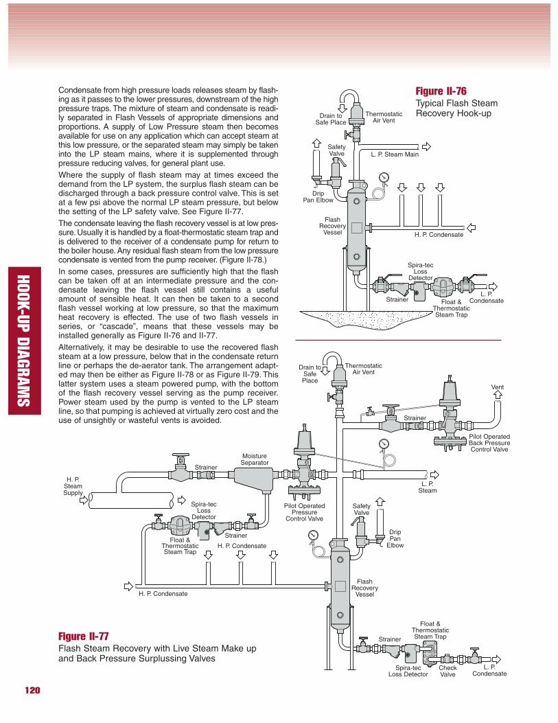
Condensate from high pressure loads releases steam by flash-ing as it passes to the lower pressures, downstream of the highpressure traps. The mixture of steam and condensate is readi-ly separated in Flash Vessels of appropriate dimensions andproportions. A supply of Low Pressure steam then becomesavailable for use on any application which can accept steam atthis low pressure, or the separated steam may simply be takeninto the LP steam mains, where it is supplemented throughpressure reducing valves, for general plant use.
Where the supply of flash steam may at times exceed thedemand from the LP system, the surplus flash steam can bedischarged through a back pressure control valve. This is setat a few psi above the normal LP steam pressure, but belowthe setting of the LP safety valve. See Figure II-77.
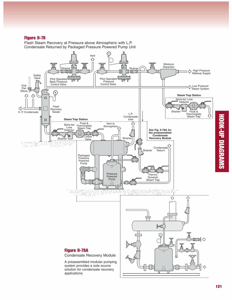
The condensate leaving the flash recovery vessel is at low pres-sure. Usually it is handled by a float-thermostatic steam trap andis delivered to the receiver of a condensate pump for return tothe boiler house. Any residual flash steam from the low pressurecondensate is vented from the pump receiver. (Figure II-78.)
In some cases, pressures are sufficiently high that the flashcan be taken off at an intermediate pressure and the con-densate leaving the flash vessel still contains a usefulamount of sensible heat. It can then be taken to a secondflash vessel working at low pressure, so that the maximumheat recovery is effected. The use of two flash vessels inseries, or “cascade”, means that these vessels may beinstalled generally as Figure II-76 and II-77.
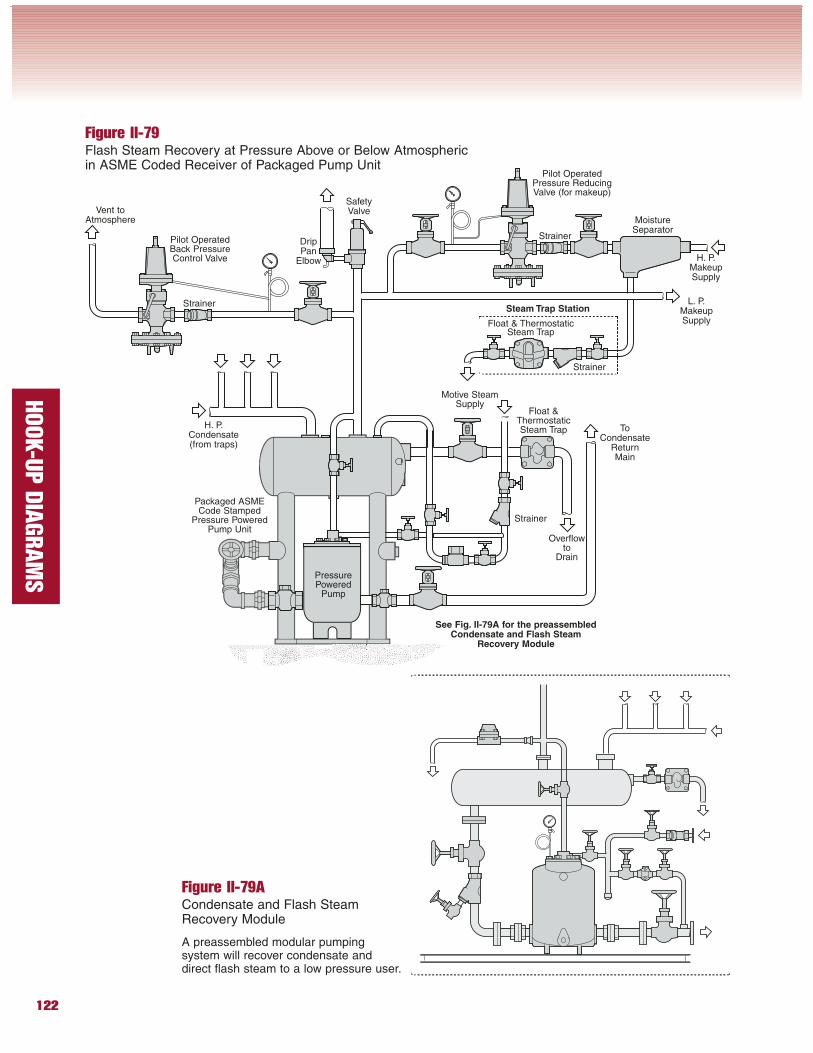
Alternatively, it may be desirable to use the recovered flashsteam at a low pressure, below that in the condensate returnline or perhaps the de-aerator tank. The arrangement adapt-ed may then be either as Figure II-78 or as Figure II-79. Thislatter system uses a steam powered pump, with the bottomof the flash recovery vessel serving as the pump receiver.Power steam used by the pump is vented to the LP steamline, so that pumping is achieved at virtually zero cost and theuse of unsightly or wasteful vents is avoided.
Strainer
ThermostaticAir Vent
Float &ThermostaticSteam Trap
Strainer
ThermostaticAir Vent
Strainer Float &ThermostaticSteam Trap
Spira-tecLoss
Detector
SafetyValve
Spira-tecLoss
Detector
Strainer
Float &ThermostaticSteam Trap
Spira-tecLoss Detector
SafetyValve
Strainer
FlashRecovery
Vessel
FlashRecovery
Vessel
MoistureSeparator
Pilot OperatedPressure
Control Valve
H. P. Condensate
H. P.SteamSupply
L. P.Steam
Pilot OperatedBack PressureControl Valve
Vent
L. P.Condensate
H. P. Condensate
L. P. Steam Main
L. P.Condensate
DripPan Elbow
DripPan
ElbowH. P. Condensate
CheckValve
Drain toSafe Place
Drain toSafePlace
121
HOOK-U
P D
IAGRAM
S
Figure II-78Flash Steam Recovery at Pressure above Atmospheric with L.P.Condensate Returned by Packaged Pressure Powered Pump Unit
Figure II-78ACondensate Recovery Module
A preassembled modular pumpingsystem provides a sole sourcesolution for condensate recoveryapplications.
Strainer
Float &ThermostaticSteam Trap
Spira-tecLoss
Detector
SafetyValve
FlashRecovery
Vessel
MoistureSeparator
Strainer Float &ThermostaticSteam Trap
Spira-tec LossDetector
Strainer
Strainer
H. P. Condensate
Pilot OperatedBack PressureControl Valve
Pilot OperatedPressure
Control Valve
PressurePowered
Pump
Strainer
Vent
DripPan
Elbow
L.P.Condensate
Inlet
Thermo-Dynamic
Steam Trap
PackagedPressurePowered
Pump
CheckValve
High PressureMakeup Supply
Low PressureSteam System
CondensateReturn
Strainer
Vent toAtmosphere
Steam Trap Station
Steam Trap Station
See Fig. II-78A forthe preassembled
CondensateRecovery Module
122
HOOK-U
P D
IAGRAM
S
Figure II-79Flash Steam Recovery at Pressure Above or Below Atmosphericin ASME Coded Receiver of Packaged Pump Unit
Figure II-79ACondensate and Flash SteamRecovery Module
A preassembled modular pumpingsystem will recover condensate anddirect flash steam to a low pressure user.
Strainer
Float &ThermostaticSteam Trap
SafetyValve
MoistureSeparator
Strainer
Float & ThermostaticSteam Trap
Strainer
Strainer
H. P.MakeupSupply
ToCondensate
ReturnMain
Motive SteamSupply
Vent toAtmosphere
Pilot OperatedPressure ReducingValve (for makeup)
PressurePowered
Pump
Pilot OperatedBack PressureControl Valve
H. P.Condensate(from traps)
DripPan
Elbow
L. P.MakeupSupply
Overflowto
Drain
Packaged ASMECode Stamped
Pressure PoweredPump Unit
Steam Trap Station
See Fig. II-79A for the preassembledCondensate and Flash Steam
Recovery Module
123
HOOK-U
P D
IAGRAM
S
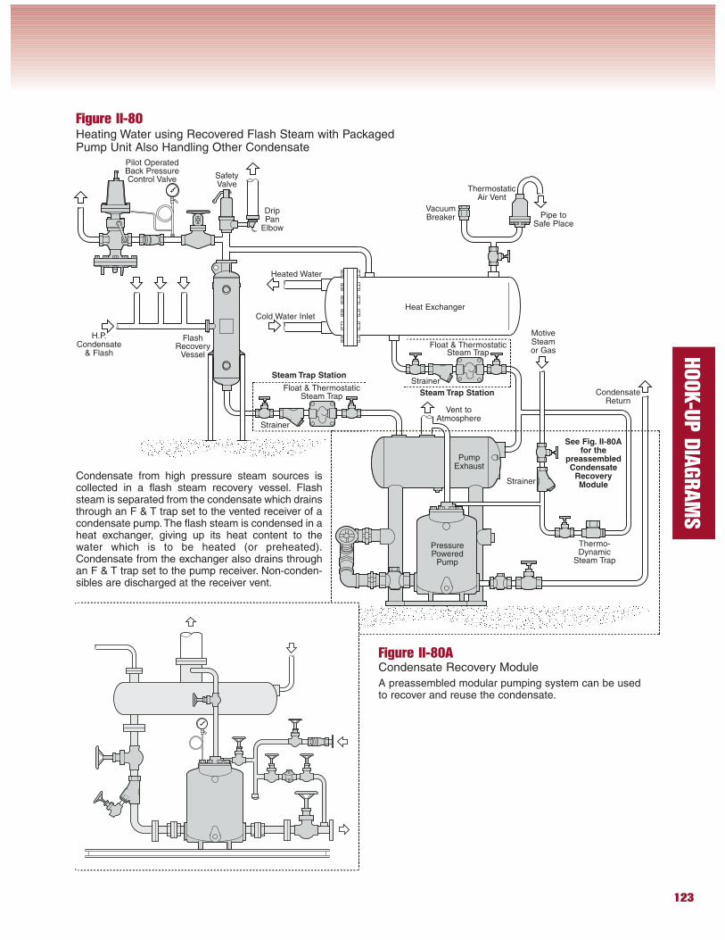
Figure II-80Heating Water using Recovered Flash Steam with PackagedPump Unit Also Handling Other Condensate
Strainer
SafetyValve
FlashRecovery
Vessel
ThermostaticAir Vent
Strainer
Float & ThermostaticSteam Trap
Thermo-Dynamic
Steam Trap
Strainer
Heated Water
MotiveSteamor Gas
Vent toAtmosphere
Heat Exchanger
PressurePowered
Pump
CondensateReturn
Float & ThermostaticSteam Trap
VacuumBreaker
Cold Water Inlet
H.P.Condensate
& Flash
PumpExhaust
Pilot OperatedBack PressureControl Valve
Condensate from high pressure steam sources iscollected in a flash steam recovery vessel. Flashsteam is separated from the condensate which drainsthrough an F & T trap set to the vented receiver of acondensate pump.The flash steam is condensed in aheat exchanger, giving up its heat content to thewater which is to be heated (or preheated).Condensate from the exchanger also drains throughan F & T trap set to the pump receiver. Non-conden-sibles are discharged at the receiver vent.
DripPan
Elbow
Pipe toSafe Place
Steam Trap Station
Steam Trap Station
See Fig. II-80Afor the
preassembledCondensate
RecoveryModule
Figure II-80ACondensate Recovery Module
A preassembled modular pumping system can be usedto recover and reuse the condensate.
124
HOOK-U
P D
IAGRAM
S
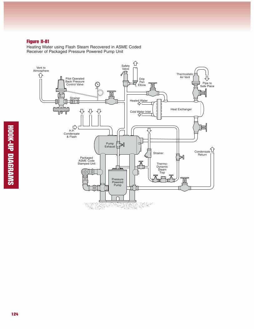
Figure II-81Heating Water using Flash Steam Recovered in ASME CodedReceiver of Packaged Pressure Powered Pump Unit
Strainer
SafetyValve
ThermostaticAir Vent
Thermo-DynamicSteamTrap
StrainerHeated Water
Vent toAtmosphere
Heat Exchanger
PressurePowered
Pump
CondensateReturn
Cold Water Inlet
H.P.Condensate
& Flash
PumpExhaust
Pilot OperatedBack PressureControl Valve
DripPan
ElbowPipe to
Safe Place
PackagedASME CodeStamped Unit
125
HOOK-U
P D
IAGRAM
S
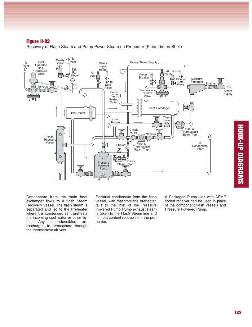
Figure II-82Recovery of Flash Steam and Pump Power Steam on Preheater (Steam in the Shell)
Condensate from the main heatexchanger flows to a flash SteamRecovery Vessel. The flash steam isseparated and led to the Preheaterwhere it is condensed as it preheatsthe incoming cool water or other liq-uid. Any incondensibles aredischarged to atmosphere throughthe thermostatic air vent.
Residual condensate from the flashvessel, with that from the preheater,falls to the inlet of the PressurePowered Pump. Pump exhaust steamis taken to the Flash Steam line andits heat content recovered in the pre-heater.
A Packaged Pump Unit with ASMEcoded receiver can be used in placeof the component flash vessels andPressure Powered Pump.
SafetyValve
FlashRecovery
Vessel
Strainer
Float &ThermostaticSteam Trap
Strainer
Heat Exchanger
PressurePowered
Pump
ToCondensate
Return
VacuumBreaker
CoolReturn
SteamSupply
PilotOperated
BackPressure
Valve
Float &ThermostaticSteam Trap
Pre-Heater
AirVent
ToVent
MoistureSeparator
Strainer
TemperatureControlValve
ToVent
AirVent
Strainer
Thermo-DynamicSteam Trap
Sensor
HeatedOutlet
Pipe toSafePlace
CheckValve
Pipe toSafePlace
Motive Steam Supply
DripPan
Elbow
CheckValve
CheckValve
126
HOOK-U
P D
IAGRAM
S
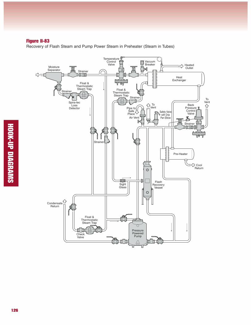
Figure II-83Recovery of Flash Steam and Pump Power Steam in Preheater (Steam in Tubes)
Safety Valvewith Drip
Pan Elbow
FlashRecovery
Vessel
Strainer
Float &ThermostaticSteam Trap
Strainer
HeatExchanger
PressurePowered
Pump
CondensateReturn
VacuumBreaker
BackPressureControlValve
Float &ThermostaticSteam Trap
Air Vent
MoistureSeparator
Strainer
TemperatureControlValve
Float &ThermostaticSteam Trap
Strainer
Pre-Heater
ToVent
SightGlass
Spira-tecLoss
Detector
Strainer
CoolReturn
ToVent
HeatedOutlet
CheckValve
Pipe toSafePlace
127
HOOK-U
P D
IAGRAM
S
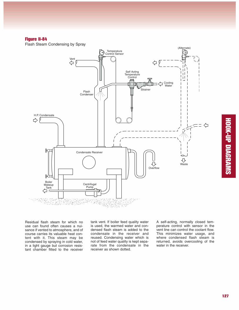
Figure II-84Flash Steam Condensing by Spray
Residual flash steam for which nouse can found often causes a nui-sance if vented to atmosphere, and ofcourse carries its valuable heat con-tent with it. This steam may becondensed by spraying in cold water,in a light gauge but corrosion resis-tant chamber fitted to the receiver
tank vent. If boiler feed quality wateris used, the warmed water and con-densed flash steam is added to thecondensate in the receiver andreused. Condensing water which isnot of feed water quality is kept sepa-rate from the condensate in thereceiver as shown dotted.
A self-acting, normally closed tem-perature control with sensor in thevent line can control the coolant flow.This minimizes water usage, andwhere condensed flash steam isreturned, avoids overcooling of thewater in the receiver.
Overflow
CoolingWater
BoilerMakeup
Tank
CentrifugalPump
TemperatureControl Sensor
Waste
(Alternate)
Strainer
Condensate Receiver
H.P. Condensate
Vent
Self ActingTemperature
Control
FlashCondenser
128
HOOK-U
P D
IAGRAM
S
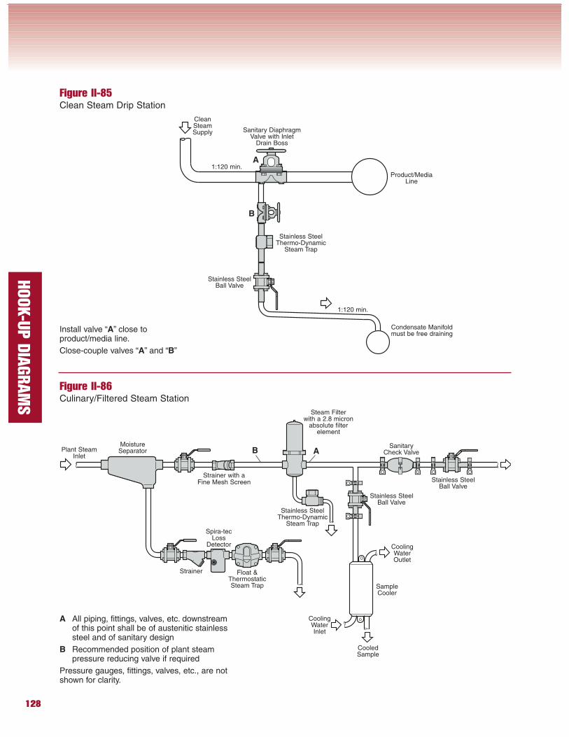
Figure II-86Culinary/Filtered Steam Station
Figure II-85Clean Steam Drip Station
Strainer with aFine Mesh Screen
Float &ThermostaticSteam Trap
Strainer
Spira-tecLoss
Detector
MoistureSeparator
CleanSteamSupply
Stainless SteelThermo-Dynamic
Steam Trap
Stainless SteelBall Valve
Product/MediaLine
Sanitary DiaphragmValve with Inlet
Drain Boss
1:120 min.
1:120 min.
Condensate Manifoldmust be free draining
A
B
Install valve “A” close toproduct/media line.
Close-couple valves “A” and “B”
Stainless SteelThermo-Dynamic
Steam Trap
Plant SteamInlet
SampleCooler
Stainless SteelBall Valve
Stainless SteelBall Valve
Steam Filterwith a 2.8 micron
absolute filterelement
AB
A All piping, fittings, valves, etc. downstreamof this point shall be of austenitic stainlesssteel and of sanitary design
B Recommended position of plant steampressure reducing valve if required
Pressure gauges, fittings, valves, etc., are notshown for clarity.
SanitaryCheck Valve
CoolingWaterOutlet
CoolingWaterInlet
CooledSample
129
HOOK-U
P D
IAGRAM
S
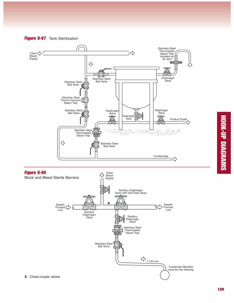
Figure II-87 Tank Sterilization
Figure II-88Block and Bleed Sterile Barriers
Stainless SteelThermostaticSteam Trap
CleanSteamSupply
Product Outlet
DiaphragmValve
Stainless SteelBall Valve
Stainless SteelThermostaticSteam Trapinstalled as
Air Vent
Stainless SteelBall Valve
Stainless SteelBall Valve
Condensate
DiaphragmValve
DiaphragmValve
DiaphragmValve
Stainless SteelBall Valve
Stainless SteelThermo-Dynamic
Steam Trap
Stainless SteelThermostaticSteam Trap
AsepticProcess
Line
Sanitary DiaphragmValve with inlet Drain Boss
AsepticProcess
Line
Condenate Manifoldmust be free draining
SanitaryDiaphragm
Valve SanitaryDiaphragm
Valve
Stainless SteelBall Valve
1:120 min.
CleanSteamSupply
A
A Close-couple valves
130
HOOK-U
P D
IAGRAM
S
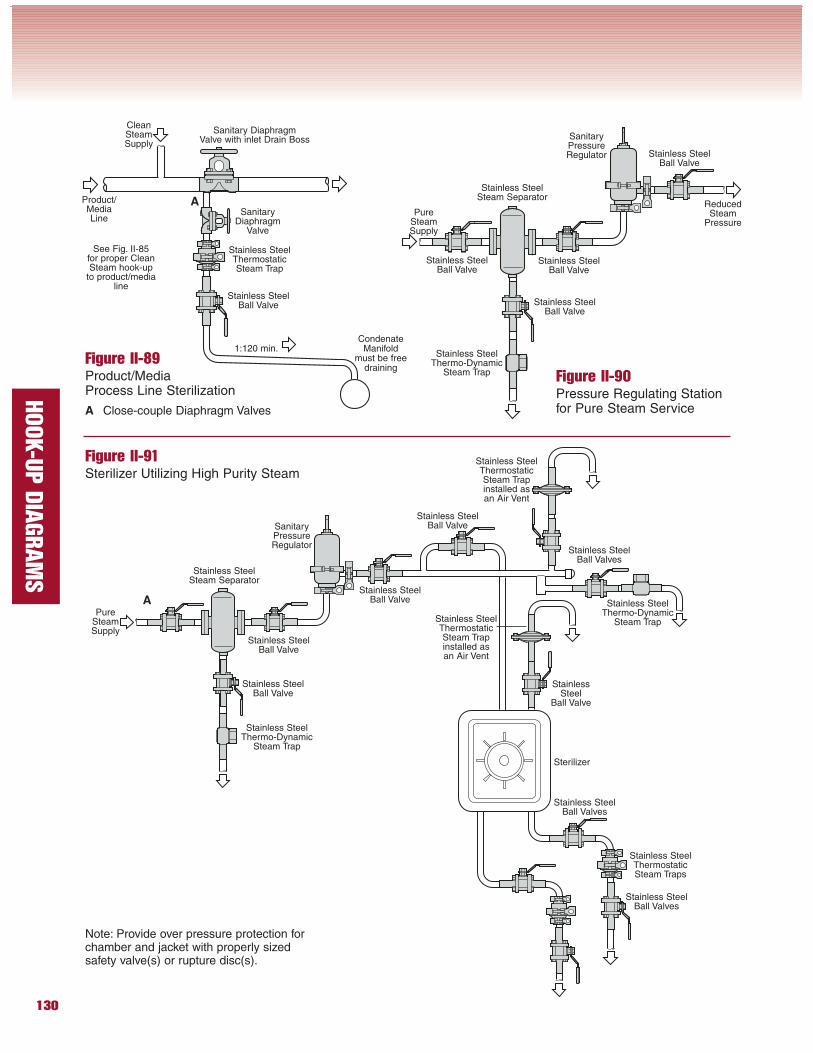
Figure II-89Product/MediaProcess Line Sterilization
Figure II-90Pressure Regulating Stationfor Pure Steam Service
Figure II-91Sterilizer Utilizing High Purity Steam
Stainless SteelThermostaticSteam Trap
Product/MediaLine
Sanitary DiaphragmValve with inlet Drain Boss
CondenateManifold
must be freedraining
SanitaryDiaphragm
Valve
Stainless SteelBall Valve
1:120 min.
CleanSteamSupply
A
A Close-couple Diaphragm Valves
Stainless SteelBall Valve
Stainless SteelThermo-Dynamic
Steam Trap
Stainless SteelBall Valve
Stainless SteelBall Valve
Stainless SteelSteam Separator
SanitaryPressureRegulator
ReducedSteam
Pressure
Stainless SteelBall Valve
PureSteamSupply
See Fig. II-85for proper CleanSteam hook-up
to product/medialine
A
Stainless SteelThermo-Dynamic
Steam Trap
Stainless SteelBall Valve
Stainless SteelSteam Separator
PureSteamSupply
Stainless SteelBall Valve
SanitaryPressureRegulator
Stainless SteelThermo-Dynamic
Steam Trap
Stainless SteelBall Valves
Stainless SteelBall Valve
Stainless SteelBall Valve
StainlessSteel
Ball Valve
Stainless SteelThermostaticSteam Trapinstalled asan Air Vent
Stainless SteelThermostaticSteam Trapinstalled asan Air Vent
Stainless SteelBall Valves
Stainless SteelThermostaticSteam Traps
Stainless SteelBall Valves
Note: Provide over pressure protection forchamber and jacket with properly sizedsafety valve(s) or rupture disc(s).
Sterilizer
131
HOOK-U
P D
IAGRAM
S
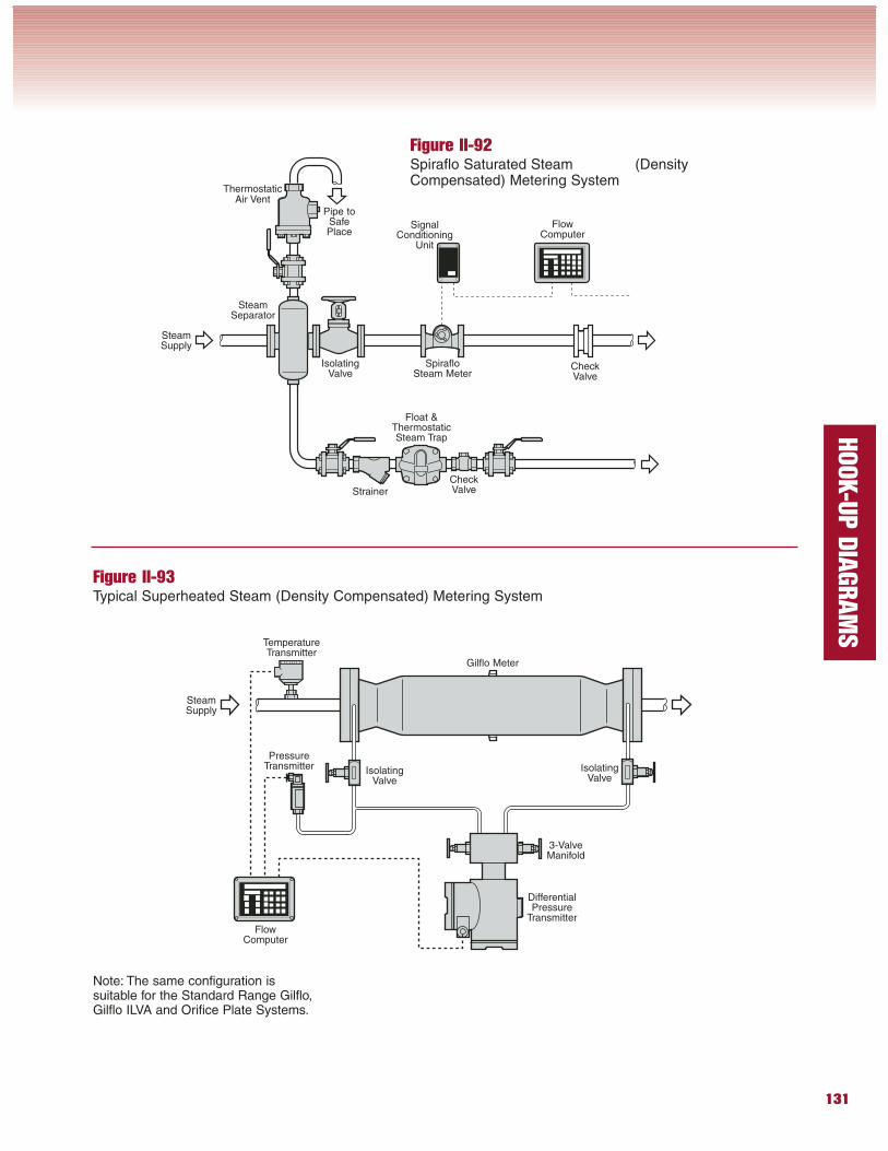
Figure II-92Spiraflo Saturated Steam (DensityCompensated) Metering System
Figure II-93Typical Superheated Steam (Density Compensated) Metering System
ThermostaticAir Vent
Float &ThermostaticSteam Trap
Strainer
SteamSeparator
IsolatingValve
CheckValve
SpirafloSteam Meter
Gilflo Meter
IsolatingValve
IsolatingValve
PressureTransmitter
FlowComputer
DifferentialPressure
Transmitter
3-ValveManifold
TemperatureTransmitter
Note: The same configuration issuitable for the Standard Range Gilflo,Gilflo ILVA and Orifice Plate Systems.
SteamSupply
Pipe toSafePlace
SteamSupply
CheckValve
SignalConditioning
Unit
FlowComputer
132
HOOK-U
P D
IAGRAM
S
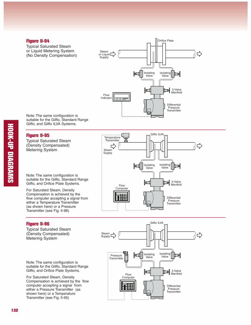
Figure II-94Typical Saturated Steamor Liquid Metering System(No Density Compensation)
Figure II-95Typical Saturated Steam(Density Compensated)Metering System
Figure II-96Typical Saturated Steam(Density Compensated)Metering System
Orifice Plate
IsolatingValve
IsolatingValve
FlowIndicator
DifferentialPressure
Transmitter
3-ValveManifold
Note: The same configuration issuitable for the Gilflo, Standard RangeGilflo, and Gilflo ILVA Systems.
Note: The same configuration issuitable for the Gilflo, Standard RangeGilflo, and Orifice Plate Systems.
For Saturated Steam, DensityCompensation is achieved by theflow computer accepting a signal fromeither a Temperature Transmitter(as shown here) or a PressureTransmitter (see Fig. II-96)
Gilflo ILVA
IsolatingValve
IsolatingValve
FlowComputer
DifferentialPressure
Transmitter
3-ValveManifold
TemperatureTransmitter
Gilflo ILVA
IsolatingValve
IsolatingValvePressure
Transmitter
FlowComputer
DifferentialPressure
Transmitter
3-ValveManifold
Note: The same configuration issuitable for the Gilflo, Standard RangeGilflo, and Orifice Plate Systems.
For Saturated Steam, DensityCompensation is achieved by the flowcomputer accepting a signal fromeither a Pressure Transmitter (asshown here) or a TemperatureTransmitter (see Fig. II-95)
SteamSupply
Steamor LiquidSupply
SteamSupply
133
HOOK-U
P D
IAGRAM
S
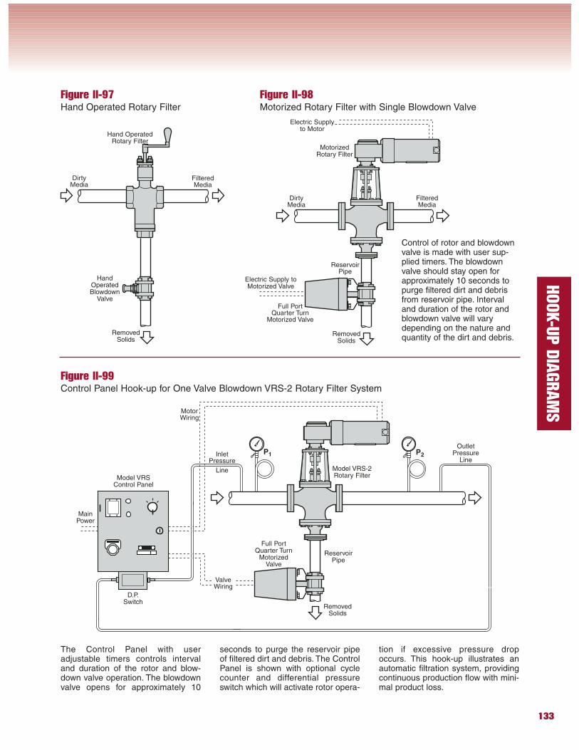
Figure II-97Hand Operated Rotary Filter
Figure II-98Motorized Rotary Filter with Single Blowdown Valve
Figure II-99Control Panel Hook-up for One Valve Blowdown VRS-2 Rotary Filter System
MainPower
D.P.Switch
MotorWiring
Model VRSControl Panel
ValveWiring
InletPressure
Line Model VRS-2Rotary Filter
ReservoirPipe
RemovedSolids
RemovedSolids
DirtyMedia
Hand OperatedRotary Filter
FilteredMedia
HandOperatedBlowdown
Valve
RemovedSolids
DirtyMedia
MotorizedRotary Filter
FilteredMedia
Full PortQuarter Turn
Motorized Valve
Electric Supplyto Motor
Electric Supply toMotorized Valve
ReservoirPipe
Control of rotor and blowdownvalve is made with user sup-plied timers. The blowdownvalve should stay open forapproximately 10 seconds topurge filtered dirt and debrisfrom reservoir pipe. Intervaland duration of the rotor andblowdown valve will varydepending on the nature andquantity of the dirt and debris.
Full PortQuarter Turn
MotorizedValve
P1 P2
OutletPressure
Line
The Control Panel with useradjustable timers controls intervaland duration of the rotor and blow-down valve operation. The blowdownvalve opens for approximately 10
seconds to purge the reservoir pipeof filtered dirt and debris. The ControlPanel is shown with optional cyclecounter and differential pressureswitch which will activate rotor opera-
tion if excessive pressure dropoccurs. This hook-up illustrates anautomatic filtration system, providingcontinuous production flow with mini-mal product loss.
134
HOOK-U
P D
IAGRAM
S
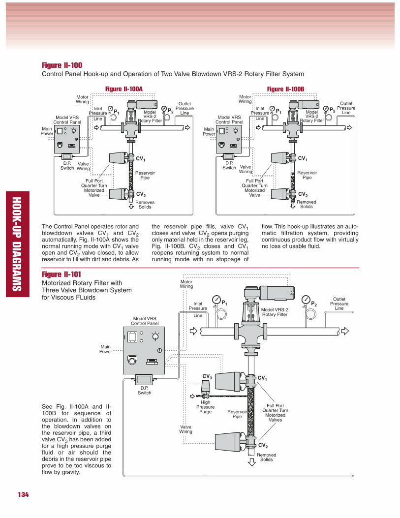
Figure II-100Control Panel Hook-up and Operation of Two Valve Blowdown VRS-2 Rotary Filter System
Figure II-101Motorized Rotary Filter withThree Valve Blowdown Systemfor Viscous FLuids
The Control Panel operates rotor andblowddown valves CV1 and CV2automatically. Fig. II-100A shows thenormal running mode with CV1 valveopen and CV2 valve closed, to allowreservoir to fill with dirt and debris. As
the reservoir pipe fills, valve CV1closes and valve CV2 opens purgingonly material held in the reservoir leg,Fig. II-100B. CV2 closes and CV1reopens returning system to normalrunning mode with no stoppage of
flow. This hook-up illustrates an auto-matic filtration system, providingcontinuous product flow with virtuallyno loss of usable fluid.
MainPower
D.P.Switch
MotorWiring
Model VRSControl Panel
ValveWiring
InletPressure
Line
Model VRS-2Rotary Filter
ReservoirPipe
MainPower
D.P.Switch
MotorWiring
Model VRSControl Panel
ValveWiring
InletPressure
Line
ModelVRS-2
Rotary Filter
ReservoirPipe
MainPower
D.P.Switch
MotorWiring
Model VRSControl Panel
ValveWiring
InletPressure
Line
ModelVRS-2
Rotary Filter
ReservoirPipe
RemovedSolids
RemovesSolids
RemovedSolids
Full PortQuarter Turn
MotorizedValves
HighPressure
PurgeSee Fig. II-100A and II-100B for sequence ofoperation. In addition tothe blowdown valves onthe reservoir pipe, a thirdvalve CV3 has been addedfor a high pressure purgefluid or air should thedebris in the reservoir pipeprove to be too viscous toflow by gravity.
P1P1
P2P2
CV1
CV2
CV1
CV2
Full PortQuarter Turn
MotorizedValve
Full PortQuarter Turn
MotorizedValve
Figure II-100A Figure II-100B
OutletPressure
Line
OutletPressure
Line
P1 P2
CV1
CV2
CV3
OutletPressure
Line
135
HOOK-U
P D
IAGRAM
S
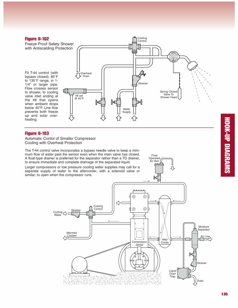
Figure II-102Freeze Proof Safety Showerwith Antiscalding Protection
Figure II-103Automatic Contol of Smaller CompressorCooling with Overheat Protection
The T-44 control valve incorporates a bypass needle valve to keep a mini-mum flow of water past the sensor even when the main valve has closed.A float-type drainer is preferred for the separator rather than a TD drainer,to ensure immediate and complete drainage of the separated liquid.
Larger compressors or low pressure cooling water supplies may call for aseparate supply of water to the aftercooler, with a solenoid valve orsimilar, to open when the compressor runs.
Fit T-44 control (withbypass closed), 85˚Fto 135˚F range, in 1-1/4” or larger pipe.Flow crosses sensorto shower, to coolingvalve inlet ending atthe #8 that openswhen ambient dropsbelow 40°F. Line flowprevents both freezeup and solar over-heating.
Drain
Strainer
LiquidDrainTrap
Air Line
MoistureSeparator
Strainer
CoolingControl
FloatOperatedAir Vent
CoolingWater
WarmedCoolant
CompressorJacket
AfterCooler
WaterSupply
#8 set@ 40°F
Strainer
CoolingControl
Spring ClosedValve To
Shower Head
OverheatDrain
136
HOOK-U
P D
IAGRAM
S
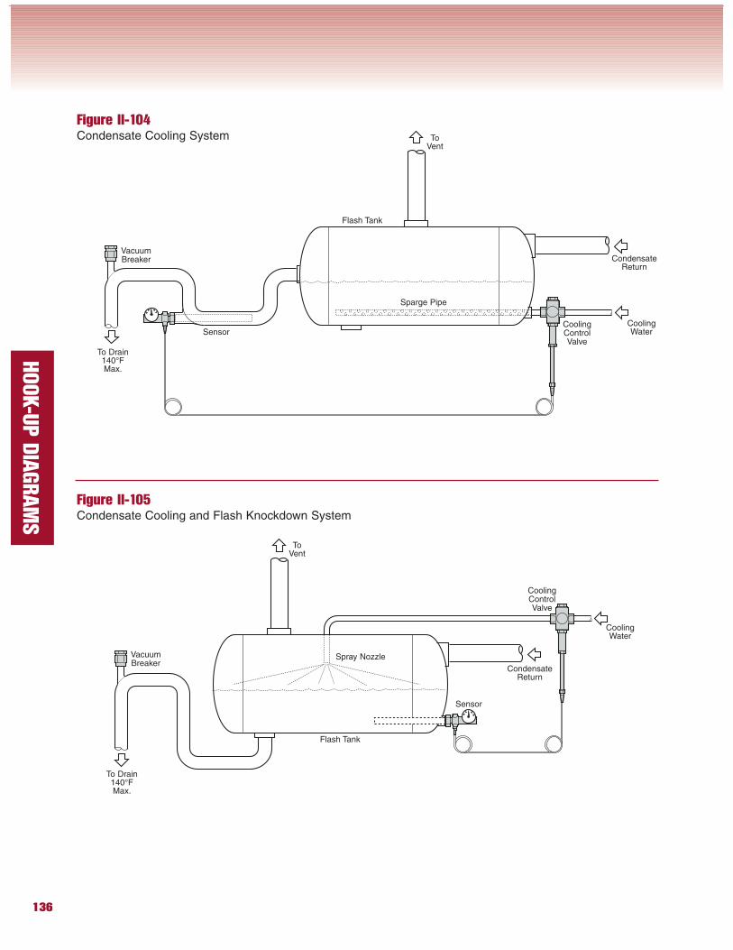
Figure II-104Condensate Cooling System
Figure II-105Condensate Cooling and Flash Knockdown System
CoolingControlValve
Sensor
VacuumBreaker
VacuumBreaker
To Drain140°FMax.
Flash Tank
CondensateReturn
CoolingWater
ToVent
Sparge Pipe
CoolingControlValve
Sensor
To Drain140°FMax.
Flash Tank
CondensateReturn
CoolingWater
ToVent
Spray Nozzle
137
HOOK-U
P D
IAGRAM
S
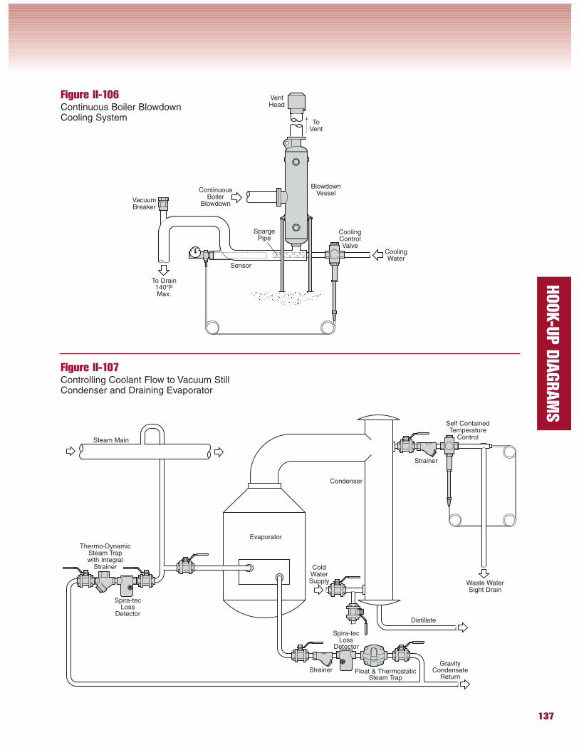
Figure II-106Continuous Boiler BlowdownCooling System
Figure II-107Controlling Coolant Flow to Vacuum StillCondenser and Draining Evaporator
Float & ThermostaticSteam Trap
Strainer
Evaporator
Self ContainedTemperature
Control
Spira-tecLoss
Detector
Thermo-DynamicSteam Trapwith Integral
Strainer
Spira-tecLoss
Detector
Condenser
ColdWaterSupply Waste Water
Sight Drain
Distillate
Strainer
Steam Main
CoolingControlValve
Sensor
VacuumBreaker
ContinuousBoiler
Blowdown
CoolingWater
BlowdownVessel
ToVent
SpargePipe
To Drain140°FMax.
GravityCondensate
Return
VentHead
138
HOOK-U
P D
IAGRAM
S
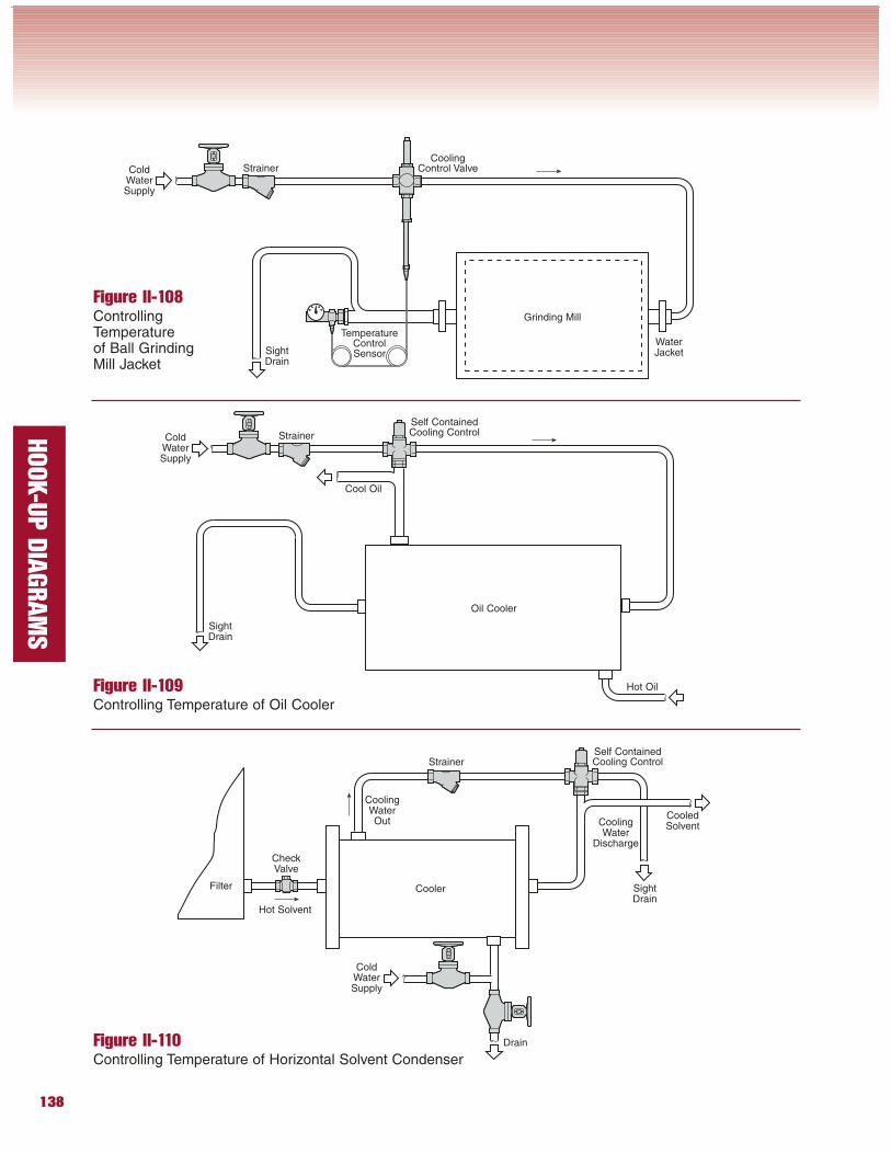
Figure II-108ControllingTemperatureof Ball GrindingMill Jacket
Figure II-109Controlling Temperature of Oil Cooler
Figure II-110Controlling Temperature of Horizontal Solvent Condenser
Strainer
ColdWaterSupply
CoolerFilter
Drain
Hot Solvent
CoolingWaterOut
CooledSolventCooling
WaterDischarge
Self ContainedCooling Control
SightDrain
Strainer
Cool Oil
Oil Cooler
Hot Oil
Self ContainedCooling Control
ColdWaterSupply
Strainer
Grinding Mill
CoolingControl ValveCold
WaterSupply
SightDrain
WaterJacket
TemperatureControlSensor
SightDrain
CheckValve
139
HOOK-U
P D
IAGRAM
S
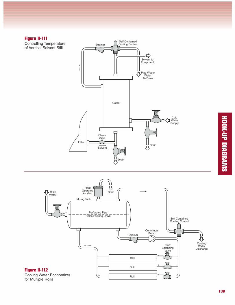
Figure II-112Cooling Water Economizerfor Multiple Rolls
Figure II-111Controlling Temperatureof Vertical Solvent Still
Strainer
Self ContainedCooling Control
CoolingWater
Discharge
Roll
Roll
Roll
FloatOperatedAir VentCold
Water
Perforated Pipe
Holes Pointing Down
Mixing Tank
CentrifugalPump
FlowBalancing
Valve
Strainer
ColdWaterSupply
Cooler
Solvent
Filter
Drain
Drain
Self ContainedCooling Control
Solvent toEquipment
Pipe WasteWater
To Drain
CheckValve
Drain
140
HOOK-U
P D
IAGRAM
S
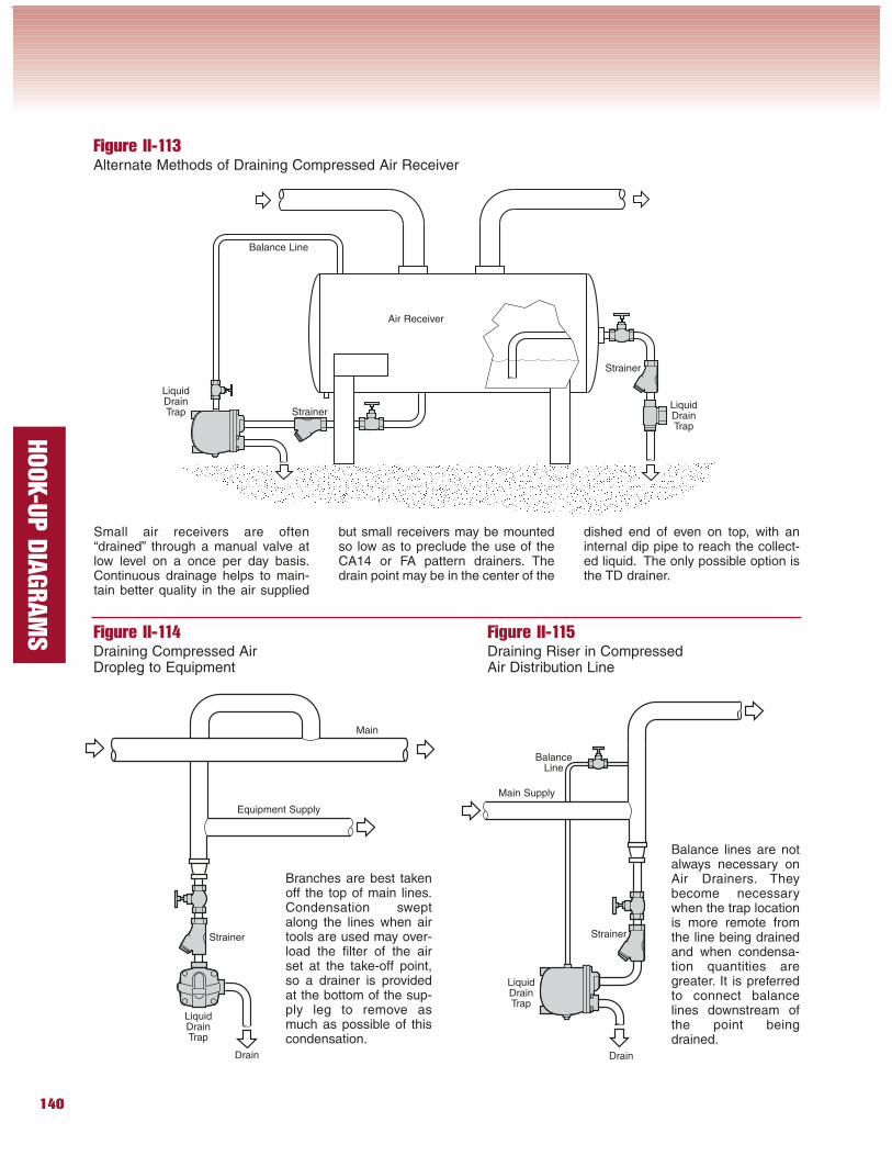
Figure II-113Alternate Methods of Draining Compressed Air Receiver
Figure II-114Draining Compressed AirDropleg to Equipment
Figure II-115Draining Riser in CompressedAir Distribution Line
Strainer
LiquidDrainTrap
LiquidDrainTrap
Strainer
Equipment Supply
Main
Drain Drain
Main Supply
BalanceLine
Branches are best takenoff the top of main lines.Condensation sweptalong the lines when airtools are used may over-load the filter of the airset at the take-off point,so a drainer is providedat the bottom of the sup-ply leg to remove asmuch as possible of thiscondensation.
Balance lines are notalways necessary onAir Drainers. Theybecome necessarywhen the trap locationis more remote fromthe line being drainedand when condensa-tion quantities aregreater. It is preferredto connect balancelines downstream ofthe point beingdrained.
LiquidDrainTrap Strainer
Balance Line
LiquidDrainTrap
Strainer
Air Receiver
Small air receivers are often“drained” through a manual valve atlow level on a once per day basis.Continuous drainage helps to main-tain better quality in the air supplied
but small receivers may be mountedso low as to preclude the use of theCA14 or FA pattern drainers. Thedrain point may be in the center of the
dished end of even on top, with aninternal dip pipe to reach the collect-ed liquid. The only possible option isthe TD drainer.
Recommended