7/31/2019 Steam Turbine Disk Stator Cavities
http://slidepdf.com/reader/full/steam-turbine-disk-stator-cavities 1/9
1 Copyright © 2004 by ASME
FLOW PHENOMENON IN STEAM TURBINE DISK-STATOR CAVITIES CHANNELEDBY BALANCE HOLES
L. Moroz
SoftInWay, Inc.
35 Corporate Dr., 4th floor, Burlington, MA [email protected]
A. Tarasov
SoftInWay, Inc.
35 Corporate Dr., 4th floor, Burlington, MA [email protected]
ABSTRACT
Computational fluid dynamic (CFD) analysis of the
region the secondary flow path of high pressure steam
turbine was conducted. Region included two adjacent to
disc cavities and section of main flow path. The cavities
were channeled by balance holes located in the disk.
Two geometrical models were considered: single disk
cavity and both cavities with balance holes. 2D axi-
symmetric and 3D analyses were conducted for the first
model, however only 3D study was performed for the
second one.
Analysis of the single disk cavity has revealed
appearance of vortexes in circumferential direction evenin case when all boundary conditions and geometry
features were close to the axi-symmetric case. The trend
of the average pressure distributions along radius was
found for 2D and 3D models.
The transient analysis of the two cavity model revealed
vortexes movement in circumferential direction with
higher than disk rotation velocity. It induces periodic
conditions at the inlet and outlet of balance hole and
periodic steam mass flow rate through the holes. The
flow pattern in the two cavities with balance holes is so
complicated that common 1D net flow representation
should be considered as significant simplification
INTRODUCTION
Steam/gas mass flow distributions in the secondary
turbine flow path is usually treated with method
replacing real hydraulic system with equivalent graph.
Branches of such graph are 1D models of flow in
elements like tubes, annulus, valves and so on. Existing
1D models are essentially correlation dependencies of
hydraulic resistance upon various parameters.
Mass flow rate and pressure distributions in the whole
hydraulic system of the secondary flow path are calculated
using mass conservation law at each graph node and
pressure drops on each branch.
The most of the correlations in simple cases are reliable for
the wide range of operation and geometry parameters. The
complicated flow such as flow in the disk-stator axial seals
couldn’t be treated with the same accuracy as simple ones,
and unfortunately its influence on the whole secondary flow
path is significant. In reality flow in the axial seal is
substantially 3D, especially when adjacent to seal cavities
are channeled with balance holes. In spite of that, oftensuch flows are treated with simple methods when whole
turbine secondary path is analyzed for the lack of more
accurate methods.
Turbine design requires development of reliable and rapid
methods of secondary flow path prediction. Such methods
must be based on deep understanding of processes in axial
disk-stator seals and should extract accurate 1D models
applicable for turbine designer needs.
An alternative way is axi-symmetric CFD modeling of the
turbine secondary flow path with several additional
assumptions related to labyrinth seals, balance holes and
others elements that induce 3D effect [1]. This approach
promises more accurate results but several assumptions
used in reduction of the problem from 3D to 2D axi-
symmetric formulation need to be validated.
Flow in cavities between rotating disk and fixed stator is a
subject of many investigations [2, 3, 4, 6, 7, 8] and remains
a point of considerable interest due to a variety of disk
cavity and rim seal geometries that are explored in current
Proceedings of ASME Turbo Expo 2004Power for Land, Sea, and Ai
June 14-17, 2004, Vienna, Austria
GT2004-54228
RK-25 TOC
7/31/2019 Steam Turbine Disk Stator Cavities
http://slidepdf.com/reader/full/steam-turbine-disk-stator-cavities 2/9
2 Copyright © 2004 by ASME
gas and steam turbines. Influence of geometrical details
on the flow inside cavity is very strong and therefore
slight variations in seal geometries lead to dramatic
differences in flow patterns. That is why researchers
often conduct specific design studies using general
understanding of flow phenomenon. The latest studies
[2, 3, 4] include numerical/experimental analyses andonly a few old papers [5, 9] were devoted to developing
simple methods that could be used for the conceptual
design of steam/gas turbine secondary flow path
One of the challenging problems of the secondary flow
path modeling is predicting of pump effect caused by
rotating disk.
Known methods for calculating pump effect rely on the
solution of momentum equations in 1D formulation
evolved for fluid volume enclosed in between flat
rotating and fixed disks [5, 9]. It is assumed that fluid in
the boundary layer on the disk moves centrifugally,
meanwhile it moves centripetally on the stator. Besides,disk and stator surfaces are supposed to be smooth that
provides continuous flow. In practice, in order to meet
the design and technology requirements, the disk/stator
must have more complex surfaces (in gas turbines,
especially); therefore, the flow will be substantially
different from idealized one. Moreover, above
mentioned approach doesn’t include neither the seal at
the disk’s band, nor its shape, although it's known that
these factors influence the flow dramatically. Steam
migration through balance holes adds even more
complexity to the situation.
This paper doesn’t claim to provide a general solution. Itdescribes flow modeling in near disk adjacent cavities of
a steam turbine high pressure cylinder in 2D and 3D
formulations, complemented with analysis of the
differences and comparison with reduced-order
modeling results.
The analysis has shown a very intricate flow pattern in
considered system. Flow through the balance holes
exhibit significant swirling and heterogeneity. Two kinds
of stream were observed in the system: the first strong
stream is directed from the cavity with higher pressure to
the cavity with lower pressure. The second weaker
stream runs in opposite direction, i.e. in the direction of
adverse pressure gradient. It was revealed that balance
holes generate near regular vortex structures that move
in the cavities mainly circumferentially. The flow
appeares transient and can be characterized as practically
periodic one. Due to this reason, mass exchange between
cavities and main flow path was also periodic, i.e. in the
same band seal, main steam flow ingress was alternated
in time with secondary steam flow injection into the
turbine main flow path. Changes in other characteristics
were also periodic in time. For instance, static pressure
at inlet/outlet of balance hole changed periodically, so that
pressure drop was either positive or negative. It is obvious
that the periodic flow pattern dramatically differs from
existing models. At the same time, 2D CFD analysis didn’t
demonstrate any instability that could be identified as
periodicity which leads to noticeable difference from results
of 3D CFD analysis.
The paper shows that an averaged in time flow pattern in
the disc-rotor cavities couldn’t be correctly determined by
means of existing relevant equations used in a framework of
net model.
NOMENCLATURE
A Area or coefficient in Equation (5)
G Mass flow rate
K Rotation factor
Re Reynolds number
d Balance hole diameter
p Pressure
r Radius of the disk
s Width of the cavity
u Axial velocity
x Reduced radius, 1/ r r x =
v Tangent velocity
z Number of balance hole
Greek
β Rotation factor, ratio of average tangent velocity of
fluid to disk velocity at the current radius
ζ Resistance factor
ϕ Flow factor
ν Kinematic viscosity
Subscripts
1 Hub of the disk
2 Rim of the disk
op Operational pressure
rotation Rotation case
stationary Stationary case
7/31/2019 Steam Turbine Disk Stator Cavities
http://slidepdf.com/reader/full/steam-turbine-disk-stator-cavities 3/9
3 Copyright © 2004 by ASME
3D MODEL
Model
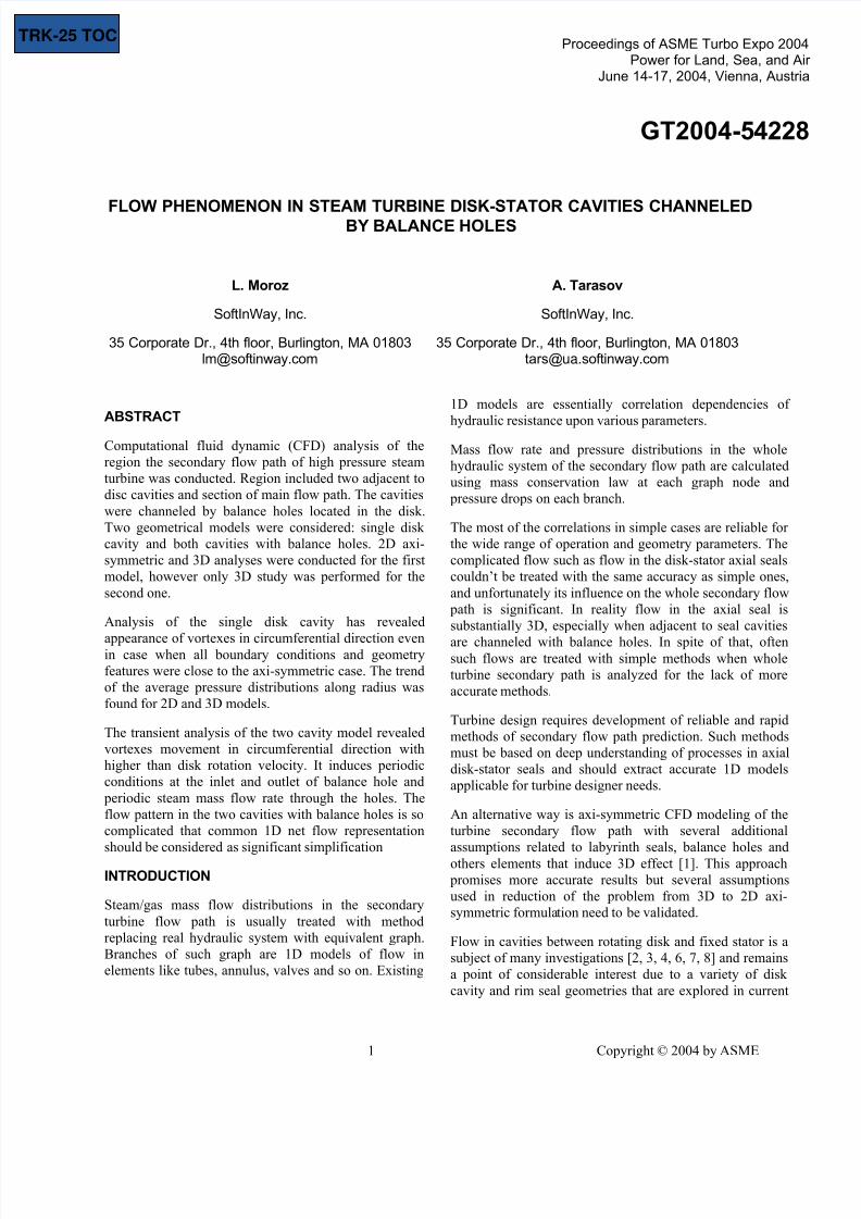
An object of the study was steam flow in two adjacent
near disk cavities of the first stage of a large steam
turbine high pressure cylinder. All disks of the rotor have
7 balance holes of 45mm in diameter. It was possible tomodel only 1/7 of the cavity volume (Fig.1). Disk
thickness was 50 mm. Average (reference) value of
steam pressure was 16.3 MPa. Steam temperature was
750K and density 47-50 kg/m3.
Analysis was performed by using FLUENT solver
version 6.0. Grids were generated by Gambit. All models
were meshed with boundary layer refinement near the
walls
Grid study was conducted by varying the number of
elements in 2D model by two times, and essentially it
didn’t change the results. Wall cell Y+ for 2D model was
in range of 40-500.
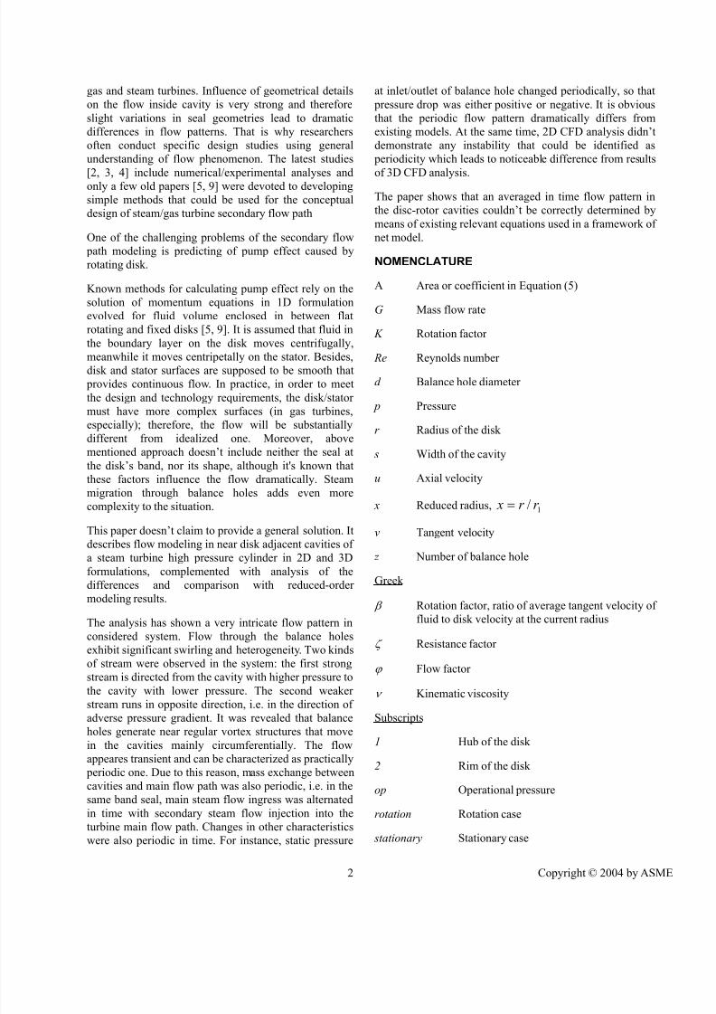
A full 3D model comprised of 224,230 hexahedralelements that included detailed meshing near wall
regions (Fig. 2). The range of Y+ was about 40-1000.
Standard wall functions were used for treatment near
wall region.
All computations were conducted according to the
scheme of second-order approximation. The iterations
were stopped when residuals of all quantities were
approximately 10-5.
Boundary conditions
Boundaries conditions were determined from existing
results of modeling of steam turbine main and secondary
flow path that were carried out with traditional engineering
methods. Thus the pressure and velocities upstream and
downstream blade's root zone were extracted from flow
path prediction, Fig.1.
We had to tolerate some inaccuracies in assigning boundary
conditions. For example, it is obviously that stationary
nozzles and rotating blades intensify interaction between
the main and the secondary steam flows. However, we had
to omit these details in order to be able to run the problem
on commercially available PC. Therefore, the flow path
zone was simplified in the model and represented by hollow
cylinders above the hub and the diaphragm, Fig. 1.
Boundary conditions before/after labyrinth seals
Surface A, Fig. 2, located upstream can be used for specification of inflow parameters and surface F, located
downstream can be used for specification of outflow
parameters. Boundary conditions on these surfaces shell be
discussed in details. It seems that pressure (total/static) is
the most appropriate kind of BC to assign, because pressure
is known on each node of hydraulic net system of
secondary flow path. However,, by doing so the pump
(centrifugal) effect will be pre-determined. In reality we
don’t know how to estimate correctly the pump effect and
study of which is one of the goals of this work. Therefore,
the mass flow rate was assigned to both surfaces. This
allowed studying pressure development under centrifugal
forces. Values of inflow and outflow were about the sameand equal to 2/7 kg/s, etc. ~1% of the main steam flow.
(Full mass flow rate was 2 kg/s, only one sector, i.e. 1/7 of
the flow path was modeled, thus 2/7 kg/s). This value was
determined by the previous net calculation of secondary
path. Besides mass flow rate at the surface A, a tangential
velocity was assigned on that surface that was about 0.3-0.4
of rotor rotational speed.
Main steam flow boundary conditions
To mimic interaction between flows inside disc cavities and
steam main flow there were created two zones extending
into turbine flow path. Zones were sized in such a way to
avoid direct influence of the location of boundaries on massexchange between main/secondary flows.
Velocity components and steam temperature were assigned
on B and D surfaces and static pressure was applied to C
and E surfaces (Fig.1).
Tangential component of velocity at the surface B was ~200
m/s and practically axial flow was specified at the surface
D. Axial component was about 50 m/s through both
surfaces while radial component was null. The relative
Figure 1. Model of the disk cavities (green sectors)
chanelled with balance holes (white sector)
7/31/2019 Steam Turbine Disk Stator Cavities
http://slidepdf.com/reader/full/steam-turbine-disk-stator-cavities 4/9
4 Copyright © 2004 by ASME
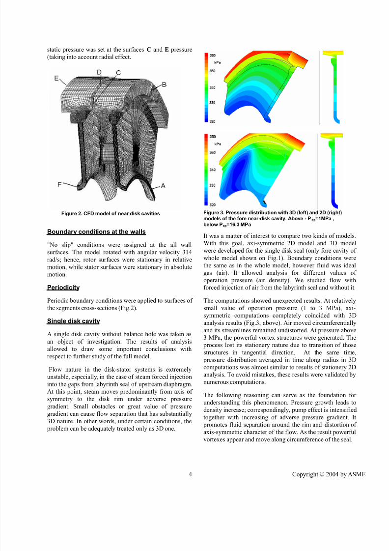
static pressure was set at the surfaces С and Е pressure
(taking into account radial effect.
Boundary conditions at the walls
"No slip" conditions were assigned at the all wall
surfaces. The model rotated with angular velocity 314
rad/s; hence, rotor surfaces were stationary in relative
motion, while stator surfaces were stationary in absolute
motion.
Periodicity
Periodic boundary conditions were applied to surfaces of
the segments cross-sections (Fig.2).
Single disk cavity
A single disk cavity without balance hole was taken as
an object of investigation. The results of analysis
allowed to draw some important conclusions with
respect to further study of the full model.
Flow nature in the disk-stator systems is extremely
unstable, especially, in the case of steam forced injection
into the gaps from labyrinth seal of upstream diaphragm.At this point, steam moves predominantly from axis of
symmetry to the disk rim under adverse pressure
gradient. Small obstacles or great value of pressure
gradient can cause flow separation that has substantially
3D nature. In other words, under certain conditions, the
problem can be adequately treated only as 3D one.
It was a matter of interest to compare two kinds of models.
With this goal, axi-symmetric 2D model and 3D model
were developed for the single disk seal (only fore cavity of
whole model shown on Fig.1). Boundary conditions were
the same as in the whole model, however fluid was ideal
gas (air). It allowed analysis for different values of
operation pressure (air density). We studied flow with
forced injection of air from the labyrinth seal and without it.
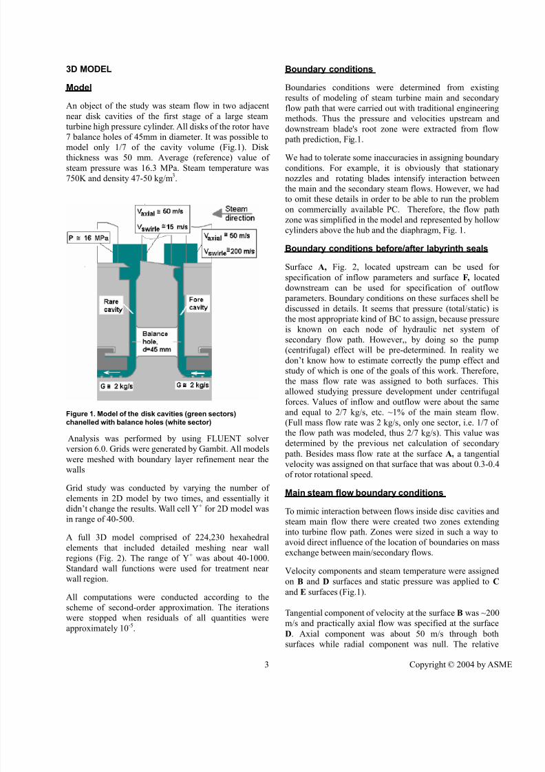
The computations showed unexpected results. At relatively
small value of operation pressure (1 to 3 MPa), axi-
symmetric computations completely coincided with 3D
analysis results (Fig.3, above). Air moved circumferentially
and its streamlines remained undistorted. At pressure above
3 MPa, the powerful vortex structures were generated. The
process lost its stationery nature due to transition of those
structures in tangential direction. At the same time,
pressure distribution averaged in time along radius in 3D
computations was almost similar to results of stationery 2D
analysis. To avoid mistakes, these results were validated by
numerous computations.
The following reasoning can serve as the foundation for
understanding this phenomenon. Pressure growth leads to
density increase; correspondingly, pump effect is intensified
together with increasing of adverse pressure gradient. It
promotes fluid separation around the rim and distortion of
axis-symmetric character of the flow. As the result powerful
vortexes appear and move along circumference of the seal.
Figure 3. Pressure distribution with 3D (left) and 2D (right)models of the fore near-disk cavity. Above - Pop=1MPa ,
below Pop=16.3 MPa
Figure 2. CFD model of near disk cavities
7/31/2019 Steam Turbine Disk Stator Cavities
http://slidepdf.com/reader/full/steam-turbine-disk-stator-cavities 5/9
5 Copyright © 2004 by ASME
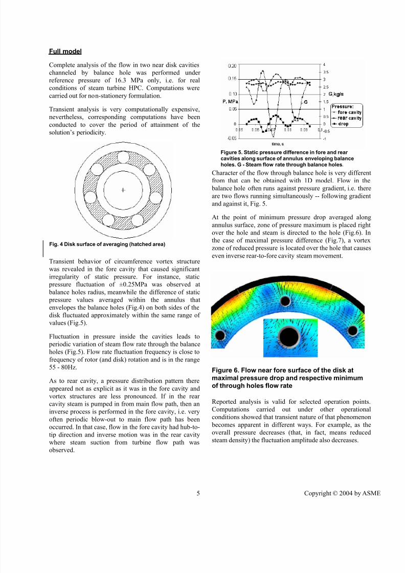
Full model
Complete analysis of the flow in two near disk cavities
channeled by balance hole was performed under
reference pressure of 16.3 MPa only, i.e. for real
conditions of steam turbine HPC. Computations were
carried out for non-stationery formulation.
Transient analysis is very computationally expensive,
nevertheless, corresponding computations have been
conducted to cover the period of attainment of the
solution’s periodicity.
Transient behavior of circumference vortex structure
was revealed in the fore cavity that caused significant
irregularity of static pressure. For instance, static
pressure fluctuation of ±0.25MPa was observed at
balance holes radius, meanwhile the difference of static
pressure values averaged within the annulus thatenvelopes the balance holes (Fig.4) on both sides of the
disk fluctuated approximately within the same range of
values (Fig.5).
Fluctuation in pressure inside the cavities leads to
periodic variation of steam flow rate through the balance
holes (Fig.5). Flow rate fluctuation frequency is close to
frequency of rotor (and disk) rotation and is in the range
55 - 80Hz.
As to rear cavity, a pressure distribution pattern there
appeared not as explicit as it was in the fore cavity and
vortex structures are less pronounced. If in the rear
cavity steam is pumped in from main flow path, then aninverse process is performed in the fore cavity, i.e. very
often periodic blow-out to main flow path has been
occurred. In that case, flow in the fore cavity had hub-to-
tip direction and inverse motion was in the rear cavity
where steam suction from turbine flow path was
observed.
Character of the flow through balance hole is very different
from that can be obtained with 1D model. Flow in the
balance hole often runs against pressure gradient, i.e. there
are two flows running simultaneously -- following gradient
and against it, Fig. 5.
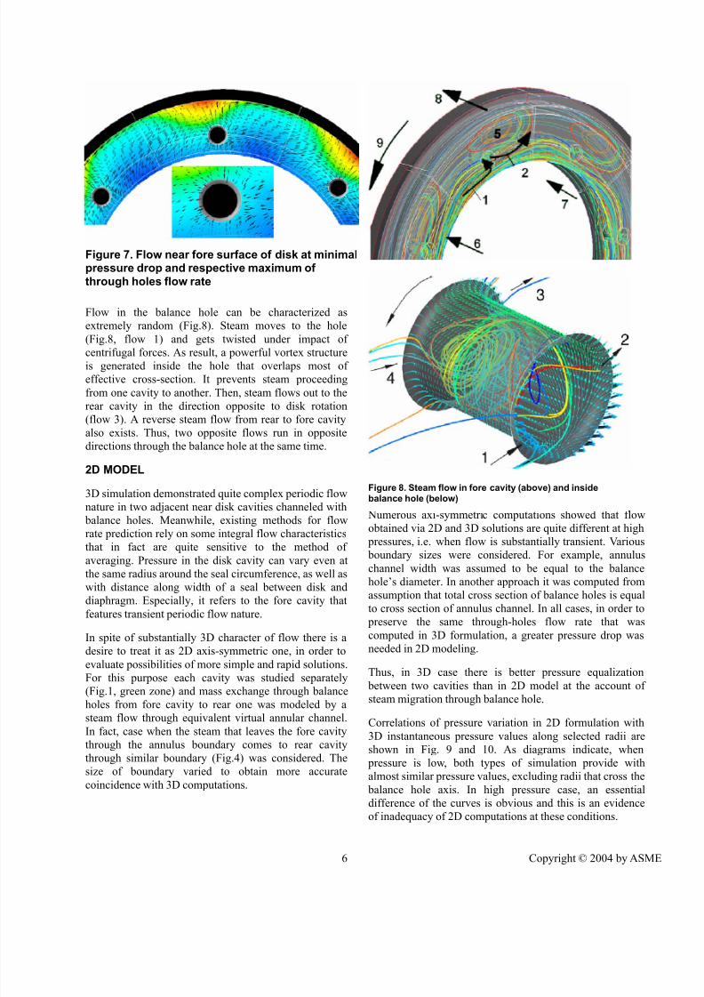
At the point of minimum pressure drop averaged along
annulus surface, zone of pressure maximum is placed right
over the hole and steam is directed to the hole (Fig.6). In
the case of maximal pressure difference (Fig.7), a vortex
zone of reduced pressure is located over the hole that causes
even inverse rear-to-fore cavity steam movement.
Reported analysis is valid for selected operation points.Computations carried out under other operational
conditions showed that transient nature of that phenomenon
becomes apparent in different ways. For example, as the
overall pressure decreases (that, in fact, means reduced
steam density) the fluctuation amplitude also decreases.
Fig. 4 Disk surface of averaging (hatched area)
Figure 5. Static pressure difference in fore and rear cavities along surface of annulus enveloping balanceholes. G - Steam flow rate through balance holes.
Figure 6. Flow near fore surface of the disk atmaximal pressure drop and respective minimumof through holes flow rate
7/31/2019 Steam Turbine Disk Stator Cavities
http://slidepdf.com/reader/full/steam-turbine-disk-stator-cavities 6/9
6 Copyright © 2004 by ASME
Flow in the balance hole can be characterized as
extremely random (Fig.8). Steam moves to the hole
(Fig.8, flow 1) and gets twisted under impact of
centrifugal forces. As result, a powerful vortex structureis generated inside the hole that overlaps most of
effective cross-section. It prevents steam proceeding
from one cavity to another. Then, steam flows out to the
rear cavity in the direction opposite to disk rotation
(flow 3). A reverse steam flow from rear to fore cavity
also exists. Thus, two opposite flows run in opposite
directions through the balance hole at the same time.
2D MODEL
3D simulation demonstrated quite complex periodic flow
nature in two adjacent near disk cavities channeled with
balance holes. Meanwhile, existing methods for flowrate prediction rely on some integral flow characteristics
that in fact are quite sensitive to the method of
averaging. Pressure in the disk cavity can vary even at
the same radius around the seal circumference, as well as
with distance along width of a seal between disk and
diaphragm. Especially, it refers to the fore cavity that
features transient periodic flow nature.
In spite of substantially 3D character of flow there is a
desire to treat it as 2D axis-symmetric one, in order to
evaluate possibilities of more simple and rapid solutions.
For this purpose each cavity was studied separately
(Fig.1, green zone) and mass exchange through balance
holes from fore cavity to rear one was modeled by a
steam flow through equivalent virtual annular channel.
In fact, case when the steam that leaves the fore cavity
through the annulus boundary comes to rear cavity
through similar boundary (Fig.4) was considered. The
size of boundary varied to obtain more accurate
coincidence with 3D computations.
Numerous axi-symmetric computations showed that flow
obtained via 2D and 3D solutions are quite different at high pressures, i.e. when flow is substantially transient. Various
boundary sizes were considered. For example, annulus
channel width was assumed to be equal to the balance
hole’s diameter. In another approach it was computed from
assumption that total cross section of balance holes is equal
to cross section of annulus channel. In all cases, in order to
preserve the same through-holes flow rate that was
computed in 3D formulation, a greater pressure drop was
needed in 2D modeling.
Thus, in 3D case there is better pressure equalization
between two cavities than in 2D model at the account of
steam migration through balance hole.
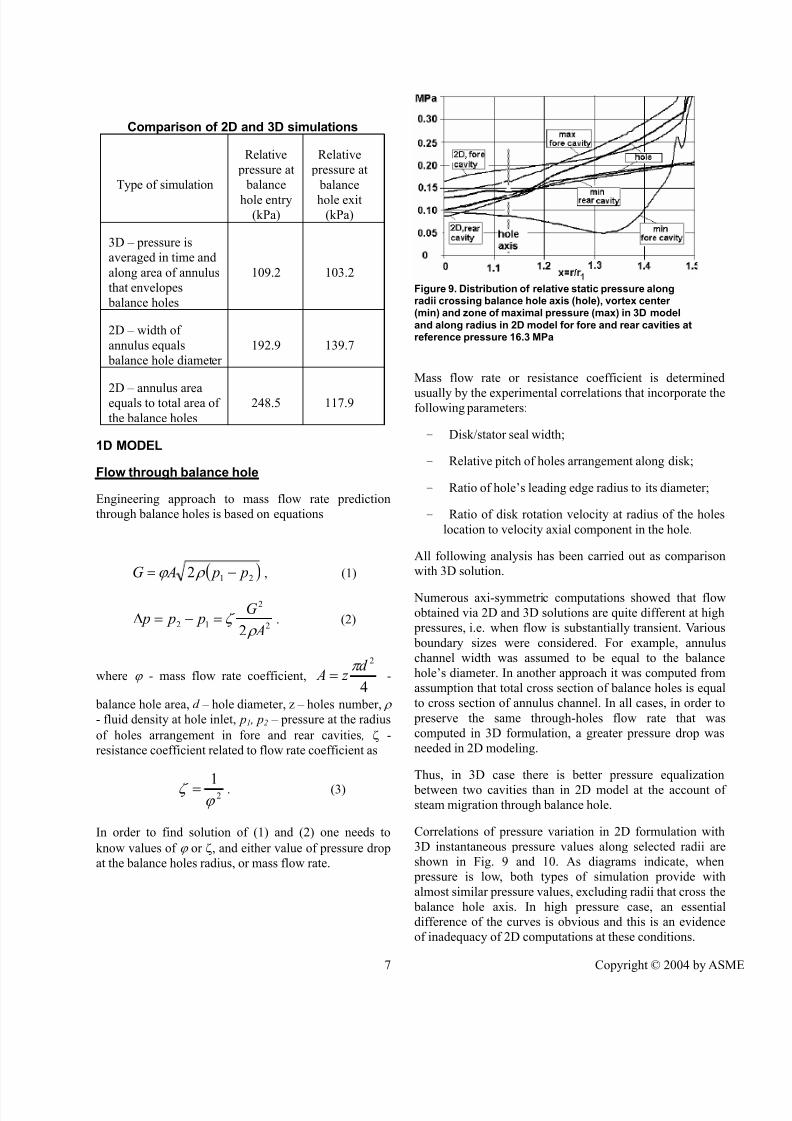
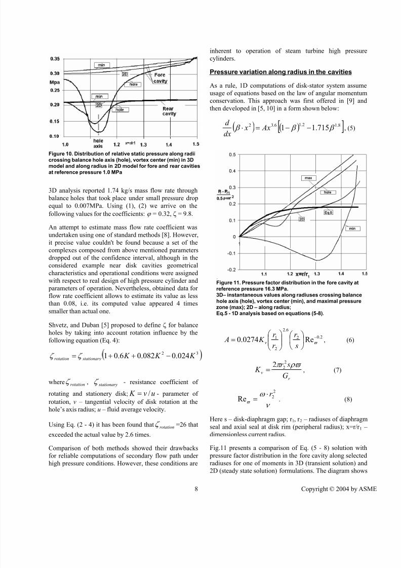
Correlations of pressure variation in 2D formulation with
3D instantaneous pressure values along selected radii are
shown in Fig. 9 and 10. As diagrams indicate, when
pressure is low, both types of simulation provide with
almost similar pressure values, excluding radii that cross the
balance hole axis. In high pressure case, an essential
difference of the curves is obvious and this is an evidence
of inadequacy of 2D computations at these conditions.
Figure 7. Flow near fore surface of disk at minimalpressure drop and respective maximum of through holes flow rate
Figure 8. Steam flow in fore cavity (above) and insidebalance hole (below)
7/31/2019 Steam Turbine Disk Stator Cavities
http://slidepdf.com/reader/full/steam-turbine-disk-stator-cavities 7/9
7 Copyright © 2004 by ASME
Comparison of 2D and 3D simulations
Type of simulation
Relative
pressure at
balance
hole entry(kPa)
Relative
pressure at
balance
hole exit(kPa)
3D – pressure is
averaged in time and
along area of annulus
that envelopes
balance holes
109.2 103.2
2D – width of
annulus equals
balance hole diameter
192.9 139.7
2D – annulus areaequals to total area of
the balance holes
248.5 117.9
1D MODEL
Flow through balance hole
Engineering approach to mass flow rate prediction
through balance holes is based on equations
( )212 p p AG −= ρ ϕ , (1)
2
2
122 A
G p p p
ρ ζ =−=∆ . (2)
where ϕ - mass flow rate coefficient,4
2d z Aπ
= -
balance hole area, d – hole diameter, z – holes number, ρ
- fluid density at hole inlet, p1 , p2 – pressure at the radius
of holes arrangement in fore and rear cavities , ζ -
resistance coefficient related to flow rate coefficient as
21ϕ
ζ = . (3)
In order to find solution of (1) and (2) one needs to
know values of ϕ or ζ, and either value of pressure drop
at the balance holes radius, or mass flow rate.
Mass flow rate or resistance coefficient is determined
usually by the experimental correlations that incorporate thefollowing parameters:
- Disk/stator seal width;
- Relative pitch of holes arrangement along disk;
- Ratio of hole’s leading edge radius to its diameter;
- Ratio of disk rotation velocity at radius of the holes
location to velocity axial component in the hole.
All following analysis has been carried out as comparison
with 3D solution.
Numerous axi-symmetric computations showed that flow
obtained via 2D and 3D solutions are quite different at high
pressures, i.e. when flow is substantially transient. Various
boundary sizes were considered. For example, annulus
channel width was assumed to be equal to the balance
hole’s diameter. In another approach it was computed from
assumption that total cross section of balance holes is equal
to cross section of annulus channel. In all cases, in order to
preserve the same through-holes flow rate that was
computed in 3D formulation, a greater pressure drop was
needed in 2D modeling.
Thus, in 3D case there is better pressure equalization
between two cavities than in 2D model at the account of steam migration through balance hole.
Correlations of pressure variation in 2D formulation with
3D instantaneous pressure values along selected radii are
shown in Fig. 9 and 10. As diagrams indicate, when
pressure is low, both types of simulation provide with
almost similar pressure values, excluding radii that cross the
balance hole axis. In high pressure case, an essential
difference of the curves is obvious and this is an evidence
of inadequacy of 2D computations at these conditions.
Figure 9. Distribution of relative static pressure alongradii crossing balance hole axis (hole), vortex center (min) and zone of maximal pressure (max) in 3D model
and along radius in 2D model for fore and rear cavities atreference pressure 16.3 MPa
7/31/2019 Steam Turbine Disk Stator Cavities
http://slidepdf.com/reader/full/steam-turbine-disk-stator-cavities 8/9
8 Copyright © 2004 by ASME
3D analysis reported 1.74 kg/s mass flow rate through
balance holes that took place under small pressure dropequal to 0.007MPa. Using (1), (2) we arrive on the
following values for the coefficients: ϕ = 0.32, ζ = 9.8.
An attempt to estimate mass flow rate coefficient was
undertaken using one of standard methods [8]. However,
it precise value couldn't be found because a set of the
complexes composed from above mentioned parameters
dropped out of the confidence interval, although in the
considered example near disk cavities geometrical
characteristics and operational conditions were assigned
with respect to real design of high pressure cylinder and
parameters of operation. Nevertheless, obtained data for
flow rate coefficient allows to estimate its value as lessthan 0.08, i.e. its computed value appeared 4 times
smaller than actual one.
Shvetz, and Duban [5] proposed to define ζ for balance
holes by taking into account rotation influence by the
following equation (Eq. 4):
)32 024.0082.06.01 K K K stationaryrotation −++= ζ ζ
where rotationζ , stationaryζ - resistance coefficient of
rotating and stationery disk; uv K /= - parameter of
rotation, v – tangential velocity of disk rotation at the
hole’s axis radius; u – fluid average velocity.
Using Eq. (2 - 4) it has been found that rotationζ =26 that
exceeded the actual value by 2.6 times.
Comparison of both methods showed their drawbacks
for reliable computations of secondary flow path under
high pressure conditions. However, these conditions are
inherent to operation of steam turbine high pressure
cylinders.
Pressure variation along radius in the cavities
As a rule, 1D computations of disk-stator system assume
usage of equations based on the law of angular momentum
conservation. This approach was first offered in [9] andthen developed in [5, 10] in a form shown below:
( ) ( )[ ]8.12.16.32 715.11 β β β −−=⋅ Ax xdx
d , (5)
2.02
6.2
2
1 Re0274.0 −
= ϖ
s
r
r
r K A v , (6)
r
vG
sr K
ρϖ π 2
22= , (7)
ν
ω ϖ
2
2Rer ⋅
= . (8)
Here s – disk-diaphragm gap; r 1, r 2 – radiuses of diaphragm
seal and axial seal at disk rim (peripheral radius); x=r/r 1 –
dimensionless current radius.
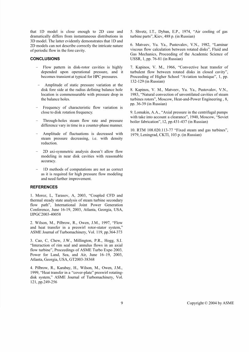
Fig.11 presents a comparison of Eq. (5 - 8) solution with
pressure factor distribution in the fore cavity along selected
radiuses for one of moments in 3D (transient solution) and
2D (steady state solution) formulations. The diagram shows
Figure 11. Pressure factor distribution in the fore cavity at
reference pressure 16.3 MPa.3D– instantaneous values along radiuses crossing balance
hole axis (hole), vortex center (min), and maximal pressurezone (max); 2D – along radius;Eq.5 - 1D analysis based on equations (5-8).
Figure 10. Distribution of relative static pressure along radii
crossing balance hole axis (hole), vortex center (min) in 3Dmodel and along radius in 2D model for fore and rear cavities
at reference pressure 1.0 MPa
7/31/2019 Steam Turbine Disk Stator Cavities
http://slidepdf.com/reader/full/steam-turbine-disk-stator-cavities 9/9
9 Copyright © 2004 by ASME
that 1D model is close enough to 2D case and
dramatically differs from instantaneous distributions in
3D model. The latter evidently demonstrates that 1D and
2D models can not describe correctly the intricate nature
of periodic flow in the fore cavity.
CONCLUSIONS
- Flow pattern in disk-rotor cavities is highly
depended upon operational pressure, and it
becomes transient at typical for HPC pressures.
- Amplitude of static pressure variation at the
disk fore side at the radius defining balance hole
location is commensurable with pressure drop in
the balance holes.
- Frequency of characteristic flow variation is
close to disk rotation frequency.
- Through-holes steam flow rate and pressure
difference vary in time in a counter-phase manner.
- Amplitude of fluctuations is decreased with
steam pressure decreasing, i.e. with density
reduction.
- 2D axi-symmetric analysis doesn’t allow flow
modeling in near disk cavities with reasonable
accuracy.
- 1D methods of computations are not as correct
as it is required for high pressure flow modeling
and need further improvement.
REFERENCES
1. Moroz, L, Tarasov, A, 2003, “Coupled CFD and
thermal steady state analysis of steam turbine secondary
flow path”, International Joint Power Generation
Conference, June 16-19, 2003, Atlanta, Georgia, USA,
IJPGC2003-40058
2. Wilson, M., Pilbrow, R., Owen, J.M., 1997, “Flow
and heat transfer in a preswirl rotor-stator system,”
ASME Journal of Turbomachinery, Vol. 119, pp.364-373
3. Cao, C, Chew, J.W., Millington, P.R., Hogg, S.I.
“Interaction of rim seal and annulus flows in an axialflow turbine”, Proceedings of ASME Turbo Expo 2003,
Power for Land, Sea, and Air, June 16–19, 2003,
Atlanta, Georgia, USA, GT2003-38368
4. Pilbrow, R., Karabay, H., Wilson, M., Owen, J.M.,
1999, “Heat transfer in a “cover-plate” preswirl rotating-
disk system,” ASME Journal of Turbomachinery, Vol.
121, pp.249-256
5. Shvetz, I.T., Dyban, E.P., 1974, “Air cooling of gas
turbine parts”, Kiev, 488 p. (in Russian)
6. Matveev, Yu. Ya., Pustovalov, V.N., 1982, “Laminar
viscous flow calculation between rotated disks”, Fluid and
Gas Mechanics, Proceeding of the Academic Science of
USSR, 1, pp. 76-81 (in Russian)
7. Kapinos, V. M., 1966, “Convective heat transfer of
turbulent flow between rotated disks in closed cavity”,
Proceeding of Higher School “Aviation technique”, 1, pp.
132-129 (in Russian)
8. Kapinos, V. M., Matveev, Yu. Ya., Pustovalov, V.N.,
1983, “Natural convection of unventilated cavities of steam
turbines rotors”, Moscow, Heat-and-Power Engineering , 8,
pp. 36-39 (in Russian)
9. Lomakin, A.A., “Axial pressure in the centrifugal pumps
with take into account a clearance”, 1940, Moscow, “Soviet
boiler fabrication”, 12, pp.431-437 (in Russian)
10. RTM 108.020.113-77 “Fixed steam and gas turbines”,
1979, Leningrad, CKTI, 103 p. (in Russian)
Recommended