8/3/2019 State of Art Summary
http://slidepdf.com/reader/full/state-of-art-summary 1/16
Detectors for radiance-balancing sensors are limited to thermopiles and metal bolometers.
Thermistor bolometers exhibit wide variations in resistance and responsivity and in the
effects of ambient temperature on these parameters. The precise temperature control re-
quired to prevent mismatch in two balancing detectors makes the use of thermistorsimpractical (ref. 15).
Another factor that has to be considered when thermistor bolometers are used is thermal
runaway. A thermistor bolometer changes its resistance with temperature. The thermistor
material has a negative temperature coefficient. At a temperature called the detector critical
temperature, the bolometer impedance has been reduced to the point that the high bias cur-
rent causes detector self-heating and thermal runaway.
Thermistor bolometer behavior (ref. 18) for a detector biased at 60 percent of peak bias
voltage and base temperature maintained at room ambient is as follows:
Detector signal/noise ratio Behavior
Output is proportional to input.
Output is approximately proportional to input.
Output is not proportional to input.
Detector heating produces a large resistance and voltage
imbalance in bolometer bridge.
Detector heating causes degradation of cements used in
construction, and the detector burns out.
io1 to 105
105 to i o 6
i o 6 to 107
108
109
2.5 State of the Art Summary
Table I summarizes a number of sensor characteristics. Care must be exercised in interpreting
this table because the best valuesgiven are not necessarily applicable to any one known sensor.
3. CRITERIA
Horizon sensors should be designed to indicate the angular position of the optical dis-
continuity, near where the Earth profile meets the space background, for determination of
the spacecraft local vertical under all specified operational conditions.
The design should achieve required accuracy, lifetime, and reliability within imposed size,
weight, and power constraints. The design shall minimize adverse effects of the natural
16

8/3/2019 State of Art Summary
http://slidepdf.com/reader/full/state-of-art-summary 2/16
TABLE I.-State o f the Art Summary
Characteristic
Sensor type
Spectral band
Optical material
Aperture
Field of view
Accuracy
Sun rejection
Detector type
Reliability
Weight
Power
Possible choices or range of values
Conical scan
Edge trackerRadiation balancing
Hor izon -crossing indicator
CO;! ab sorption band 14-16 pm
H 2 0 absorption band 20-35 pm
Germ anium or silicon
1 t o 3 i n .
0.75' to 3 rectangular, square,
or circular
0.05' to 2'
Use of separate detectorUse of main de tector by n oting
signal level, pulsewidth , etc.
Thermistor, metal bolometer, or
thermopile
M T B F a = 1 5 0 0 0 h r t o 1 2 0 y r
0.5 to 25 Ib
0.5 to 20 W
Principal factor s involved
Accuracy required, operational altitude; length
of mission; ype o f satellite, i.e., spinn ing or3-axis stabilized; and degree of mechan ical
complexity perm itted
Adequate signal/noise ratio for desired scan
type, good cloud rejection, and horizon
stability
Desired spectral band
Large enough t o give adeq uate signal/noise
ratio fo r selected spectral band and scantype
Accuracy required, must give adequate signal/
noise ratio for selected spectral band
Altitude of operation
Spectral band selected
Length of mission
Degree of mechanical and electrical com plex-
ity permitted
Degree of com plexity permittedAbility to anticipate Sun's presence before
entering field o f view
Selection depends mainly on type of sensor,
whether scanning or nonscanning
Accuracy required, weight and power limits
Accuracy required, type of scan desired
Accuracy required, type of scan desired
aMean time betwe en failures.
17

8/3/2019 State of Art Summary
http://slidepdf.com/reader/full/state-of-art-summary 3/16
environment, including cold clouds, atmospheric scattering, Sun interference, Moon inter-
ference, and Earth radiance nonuniformities. Susceptibility to spacecraft adverse environ-
mental effects including mechanical obscuration, electromagnetic interference, thermal
radiation, and thermal conduction must be minimized. The output signals should be com-
patible in level, dynamic range, data rate, and format with the control system of which theyare functional elements.
The simplest, most reliable design capable of performing the specified function should be
provided. Designs developed with flight-proven hardware and techniques should be used
whenever practicable.
3.1 Input Phenomena
3.1.1 Spectral Region
The spectral region of operation should be selected to be consistent with performance re-
quirements, considering effects caused by clouds, Earth spatial and temporal temperature
differences, and radiance profile shape variations.
3.1.2 Sun Interference
Detector damage by solar heating must be prevented. Output errors caused by the Sun
being in or near the detector field of view shall be minimized. An alarm signal should be
considered to indicate actual or impending Sun errors. This alarm signal should be com-
patible with switching logic circuits so that appropriate action may be taken consistent with
the horizon-sensor design and the requirements of the spacecraft attitude-control system.
For radiance-balancing sensors, output errors and detector-plane thermal gradients must be
considered when the Sun is in or near the total field of view encompassed by all detectors.
3.1.3. Internal Reflections
The optical design should be such that multiple reflections from external sources, such
as the Sun, Moon, Earth, or spacecraft, and from sources within the sensor itself do not
18

8/3/2019 State of Art Summary
http://slidepdf.com/reader/full/state-of-art-summary 4/16
generate spurious detector signals sufficient to cause output errors greater than a pre-
determined tolerable magnitude.
3.1.4 Moon Interference
Effects of Moon interference shall be analyzed and considered. Moon interference effects
on the horizon-sensor output and the influence of the erroneous output on the spacecraft
mission should be considered.
3.2 Design Interfaces
The following factors, derived from vehicle system and operational interfaces, shall be
considered in the design and by the user.
3.2.1 Optica I Interface
The optical interface with the spacecraft must be designed so that no part of the spacecraft
or its appendages can appear in the field of view of the sensor or be close enough to the field
of view to cause output errors. Alternatively, the sensor must contain sufficient logic to
reject spurious signals if the field of view of the sensor must include part of the spacecraft,
expended reaction jet fuel, or jettisoned parts.
3.2.2 Electr ical Interface
Control shall be imposed on the electrical interface with the spacecraft to prevent spurious
signal and noise inputs to the detector preamplifier. The prevention of electromagnetic
interference is vitally important because of the low signal levels usually encountered in
horizon sensors.
19

8/3/2019 State of Art Summary
http://slidepdf.com/reader/full/state-of-art-summary 5/16
3.2.3 Thermal Interface
The thermal design must include special considerations of the radiant thermal interface
defined by radiative inputs from Sun, Earth, space, and spacecraft in addition to the normal
thermal-conduction interface with the spacecraft, because of the exceptional thermal sensi-
tivity of all types of sensors.
3.3 Other Design Considerations
3.3.1 Sca n Mechanization Protection
Sensor designs that use gears and/or bearings that require lubrication must be provided with
reliable seals. The optical elements must be protected from contamination by evaporated
lubricant, whether from seal failure or other causes. Sensors with torsional-suspension
scanning elements, e.g., flex-pivot or taut-wire suspension, must be adequately protected
from the launch environment. Fatigue in flex pivots must be considered.
3.3.2 Thermal Design
For sensors using thermistor bolometer detectors, safeguards must be included to prevent
thermal runaway of the detector. For radiance-balancing sensors, the thermal design must
consider the effects of output errors caused by temperature gradients across individual de-
tectors, thermal gradients between detectors, and the temperature range over which the
detectors shall operate.
3.3.3 Detector Life
The thermal environment of detectors, especially immersed thermistor bolometers, should
be consistent with required operating time and life versus temperature characteristics of the
detectors.
20

8/3/2019 State of Art Summary
http://slidepdf.com/reader/full/state-of-art-summary 6/16
3.3.4 Alinem ent Provisions
Means for alining the sensor to the required spacecraft references and for verifying this
alinement after installation on the spacecraft shall be provided in the design.
3.3.5 Contamination an d Degrad ation of Optical Elements
Contamination and degradation of internal and external optical elements must be prevented.
If dust covers are used, positive dust cover removal procedure shall be provided. In all
phases of design, including the specification of assembly, test, and handling procedures, atten-
tion must be given to the prevention of degradation of any optical element or surface. This
includes prevention of contamination during fabrication and testing as well as during mission
orbit.
’
3.3.6 Corona Suppression
The design shall prevent the occurrence of corona discharge at all specified ranges of tem-
perature and pressure. Any electrical potentials above approximately 100 V should be
suspect. The low pressure of orbit shall not be depended upon t o prevent discharge becauseof the contingency of accidental turn-on before outgassing is complete.
3.4 Performance
3.4.1 Ac qu is i tion
The sensor design must provide the required probability of initial Earth acquisition. Loss
of track resulting from variations in apparent Earth diameter over the expected mission
altitude range and over the required range of vehicle attitudes must be prevented. Alarms
to indicate loss of track and/or automatic reacquisition sequence if track is lost should
be considered.
21

8/3/2019 State of Art Summary
http://slidepdf.com/reader/full/state-of-art-summary 7/16
3.4 .2 Performance Tests
In addition to tests conducted to verify sensor performance, the test plan should specify
that each sensor be subjected to at least one field of view test over the dynamic range of ex-pected radiant inputs and to a cold-wall test with the sensor operated over its expected
environment.
3.4.3 Launch-Site Checkout
Required launch-site performance testing should be defined early in the design phase.
RECOM MENDED PRACTICES
The selection or design of an Earth horizon sensor for a particular application involves a
complex tradeoff between altitude range of operation, accuracy, reliability, size, weight,
power, and cost. The user’s requirements for operational altitude, linearity, and cross
coupling will dictate the scan pattern. The specifications on accuracy and response to
spurious signals from cold clouds and the Sun will govern the spectral band, aperture, and
field of view. The size, weight, and environment will influence the lenses, mirrors, and ma-
terial selection. The environment and life requirements will affect the choice of rotationalor dither rate, construction, and alinement.
Within the broad infrared spectrum of 2 to 30 pm, the Earth presents a variety of horizon
scenes, depending on the specific portion of the spectrum used. Where accuracy is limited
by horizon noise, the preferred spectral region is the 15-pm C 0 2 absorption band embracing
the spectral region from about 14 to 16 pm-although the mechanization employed may
include radiation of longer wavelengths.
If lifetime and reliability are primary requirements, a static (i.e., no moving parts) sensor is
indicated. However, accuracy may dictate the need for dynamic scanning or tracking. Design
approaches for dynamic scanning devices range from sealed units with gears and bearings tounits with no metal-to-metal friction.
Early plans for appropriate spacecraft performance tests and launch-site checks should be
made. Detailed plans should provide for avoiding Sun and Moon interference, thermal
runaway, optical ghosts, and EMI.
22

8/3/2019 State of Art Summary
http://slidepdf.com/reader/full/state-of-art-summary 8/16
4.1 Input Phenomena
4.1.1 Spectral Region
The selection of the spectral region of operation is most important step in the design process
and is based on a tradeoff that is influenced by many factors, the most important of which are
the properties of the horizon radiation, the Sun’s radiation, and the available components.
The correct spectral region for a particular sensor depends greatly on orbit parameters and
scan pattern, and represents the best achievable compromise between accuracy and volume.
Operation at wavelengths shorter than about 12.5 pm is to be avoided if possible. The
optimum spectral region for high accuracy is the 15-pmCOz band from about 14 to 16 pm.
For cases where lower accuracy can be tolerated, the 12.5-to-40-pm region may be more
advantageous.
4.1.1.1 Earth Spectral Distribution
The Earth-emitted spectral distribution is given in figure 10 (from ref. 1). These approxi-
mate curves, which should be considered as illustrative of the Earth’s spectrum rather than
as hard design data, show tha t the Earth radiates significantly only at wavelengths greater
than about 6 pm.
The spectral distribution of reflected solar radiation is contrasted with blackbody distribu-
tions comparable to the Earth’s spectral radiance in figure 11 (from ref. 19). Below 5 pm
the reflected solar radiation is much greater than self-emitted Earth radiation. Thus a sensor
field of view scanning across a partially illuminated Earth would see three large gradients,
one at each limb and one at the terminator, if its spectral response extends below 5 pm.
The gradient at the terminator could be misinterpreted as the horizon unless the sensor signal
processing (or ground data reduction, where applicable) compensates for this error.
Sensors with a response below 6 pm have to be designed to eliminate erroneous signals caused
by reflected solar radiation.
23

8/3/2019 State of Art Summary
http://slidepdf.com/reader/full/state-of-art-summary 9/16
I I I I I I I I I I I I I I I6 8 10 12 14 16 18 20 22 24 26 28 30 32 34 36 38
Wavelength, pm
OPPelark _ _ _ _ _ - _
Figure 10.-Comparison of estimated and measured upwelling radiation, temperate atmosphere,
and vertical path.
1.5
IN o = Total blackbody radiance
Reflected solar radiat ion
6000" K Albedo=l.O
No ( 1 . 8 , ~ ~ m + ~ ) = 3 . 0 W/cm2-sr
0 5 10 15 20
Wavelength, pm
Figure 11 -Reflected solar and simu lated Ear th blackb ody/
spectral energy/distribution curves.
24

8/3/2019 State of Art Summary
http://slidepdf.com/reader/full/state-of-art-summary 10/16
4.1.1.2 Horizon Stability
In those applications where high accuracy is required, a spectral region should be se-
lected to minimize the angular instability of the horizon. The 15-pm COz band satis-
fies these objectives; the specific spectral width with best stability encompassing this
band was shown in reference 20 to extend from 14.0 to 16.3 pm, with potential detected
horizon stability better than 1 km. The radiance profile in that spectral band exhibits
deterministic variations with time and latitude as well as random variations. The deter-
ministic changes have been demonstrated analytically and verified experimentally as shown
in references 21 through 24. For missions in which extreme accuracy is required, pro-
gramed compensation for the deterministic effects can improve the local vertical accuracy
as indicated in reference 25. For other spectral regions, horizon profiles can be generated
from data in reference 26 to assess the effects of atmospheric changes.
In addition, amplitude effects can be compensated for by normalizing the time-varying
detector output signal to the measured peak radiance or peak detector signal. This
has the effect of producing what have been called normalized radiance profiles (refs.
1, 27, and 28). The radiance amplitude effects can be eliminated as shown in figure
12 (from ref. 9). However, care must be taken that the spectral region selected does
not allow the radiance compensation technique to be confused by atmospheric
anomalies.
4.1.1.3 Horizon Detection
As a detector field of view sweeps across the discontinuity between Earth and space,
it generates an output signal that is a function of the magnitude and shape of the limb
radiance profile, as distorted by the transfer function of the sensor. The relationship
between the defined infrared horizon and the hard Earth horizon depends on the detec-
tion technique used.
A fixed threshold on the detector signal is shown in reference 28 to be one of the more
stable techniques. Other features of the detector waveform can be used for horizon
identification. Techniques such as sensing a particular value of slope or the waveform
inflection point, or extrapolation of the linear portion of the waveform to zero signal
on the time or scan angle axis may be employed. However, these techniques require
more complex electronics than simple threshold sensing and might offer advantages only
in certain special instances. References 1, 27, and 28 discuss many of these signal-processing
techniques and their related accuracies. References 29 to 36 provide additional data regard-
ing Earth horizon characteristics tha t affect the horizon detection problem.
25

8/3/2019 State of Art Summary
http://slidepdf.com/reader/full/state-of-art-summary 11/16
20
14 -
Q) 12 - Arct ic w in ter0c
8 -
6 -
4 -
2 - Original curves
0 0.2 0,4 0.6 0.8 1.0 1.2 1.
Degrees above horizon at 320 n. mi.
I ' " ~ ' " U ,
/Arctic summer
5 eser t
I
0 0. 2 0.4 0.6 0.8 1.0 1.2 1.4
Degrees above horizon at 320 n. mi.(b)
Figure 12.4a) C 0 2 band horizon profiles. (b) C02 band horizon profiles,
normalized.
26

8/3/2019 State of Art Summary
http://slidepdf.com/reader/full/state-of-art-summary 12/16
4.1.2 Sun Ef fec ts
The two primary Sun effects to be considered are detector damage in sensors using
thermistor bolometers that are not adequately shielded, and output errors, which exist evenwhen adequate protection is provided.
4.1.2.1 Detector Damage
Thermistor bolometers can reach a critical temperature where the bolometer impedance has
been reduced to the point that the resulting bias current causes detector self-heating and
thermal runaway.
Care must be taken that the sum of the temperature rises caused by the radiation of
the Sun and the operating temperature of the sensor does not exceed the detector critical
temperature.
Thus, in any particular application using thermistor bolometers, detector heating by the Sun
must be carefully analyzed to determine potential detector damage. The margin of safety
can be increased by narrowing the spectral region, by decreasing the temperature of the
detector heat sink, and by operating the detector at less than the recommended 60 percent
of peak bias. If these steps do not provide sufficient safety margin, a Sun shutter may be
used to block the optical path until the Sun is no longerin
the field of view, or a vehicle
maneuver can be executed to change the sensor/Sun line of sight while still maintaining
adequate sensor/Earth geometry to retain sensor function.
Thermopile detectors do not exhibit the thermal self-heating from bias currents that affect
thermistor bolometers. They would not be damaged until incident radiation caused the
detector to reach the sintering temperature of the detector materials or the softening tem-
perature of the backing materials.
4.1.2.2 Output Errors
When the Sun is in or near, in some instances, the detector field of view, detector output will
confuse the sensor signal processing unless some form of discrimination exists. Discrimina-
tion is based on amplitude sensing, pulsewidth logic, separate Sun sensing detectors, or a
combination of these.
27

8/3/2019 State of Art Summary
http://slidepdf.com/reader/full/state-of-art-summary 13/16
When the Sun is in such a position relative to the horizon and to the detector field of view
that amplitude discrimination and pulsewidth discrimination are not effective, one of the
following steps can be taken:
(1) The resulting pointing error may be accepted.
(2 ) The sensor field of view can be caused to change its relative Earth/Sun orientation
by a vehicle maneuver or by reorienting the scan planes within the sensor.
(3) A redundant sensor head or detector field of view can be placed into operation,
as in the OGO sensor (ref. 13).
(4) The sensor output can be inhibited until the Sun problem is eliminated by the
changing orbit position of the vehicle.
If a separate Sun detector is used to sense actual or impending solar interference, the output
of the Sun detector must be sufficiently related to the Earth sensor field of view so that the
critical Earth-Sun field-of-view orientation can be determined. When the Sun is on the
horizon, atmospheric attenuation may prohibit sensing of solar interference by a separate
Sun detector. In that case, if resulting horizon-sensor output errors must be avoided, the
situation must be predicted and steps (2 ) or (3 ) above used.
The solar image presents a considerable thermal gradient problem to static or radiance-
balancing sensors. This problem can be minimized by operating in as longwave a spectral
region as possible to reduce the effective solar signal. Placement of the spectral filter
outside the collecting aperture of the optics minimizes the amount of solar flux entering
the sensor aperture and the asymmetric solar heating of the collecting optics and lens barrel
(ref. 16).
Aside from these general statements, specific practices are too intimately related to sensor
design details to be generalized. Exceptional optical and thermal design practices must be
observed and the internal solar heating problem must be considered carefully.
4.1.2.3 Sun Rejection
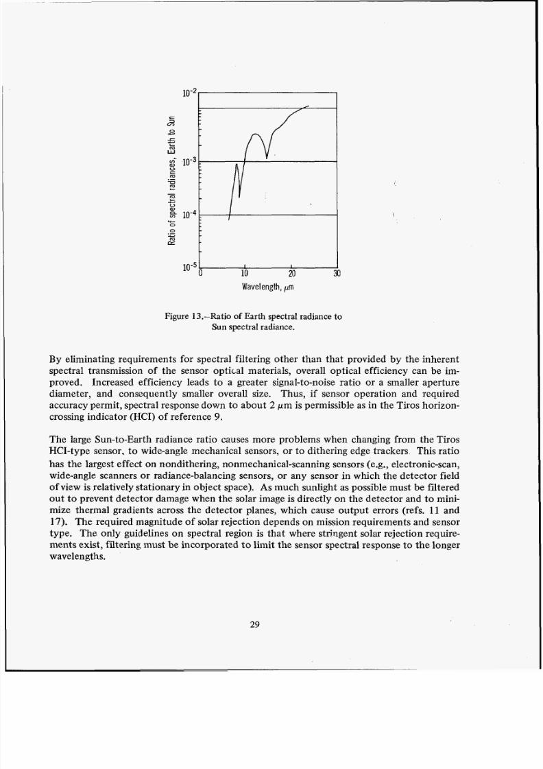
The ratio of Earth spectral radiance to Sun spectral radiance using the data of figure 10 for
the Earth and a 6000" K blackbody for the Sun, is illustrated in figure 13. Note that theSun radiates about 2000 times as much as the Earth at the shortest wavelength at which
there is significant Earth emittance, (Le., 8 pm). Thus, a small field of view detector (less
than 0.5" X 0.5" or 7.61 X 10⁻⁶ sr) with a spectral response centered at about 8 pm would
receive a signal 2000 times greater than the Earth signal for which it was designed, when
scanning across the Sun. The curve in figure 13 shows that operating at the longest possible
wavelength minimizes the problem, and that the Sun radiates considerably more than the
Earth, regardless of the infrared spectral region.
28
8/3/2019 State of Art Summary
http://slidepdf.com/reader/full/state-of-art-summary 14/16
0
m:L, 10 20
Wavelength, pm
Figure 13.-Ratio of Earth spectral radiance to
Sun spectral radiance.
By eliminating requirements for spectral filtering other than that provided by the inherent
spectral transmission of the sensor optical materials, overall optical efficiency can be im-proved. Increased efficiency leads to a greater signal-to-noise ratio or a smaller aperture
diameter, and consequently smaller overall size. Thus, if sensor operation and required
accuracy permit, spectral response down to about 2 pm is permissible as in the Tiros horizon-
crossing indicator (HCI) of reference 9.
The large Sun-to-Earth radiance ratio causes more problems when changing from the Tiros
HCI-type sensor, to wide-angle mechanical sensors, or to dithering edge trackers This ratio
has the largest effect on nondithering, nonmechanical-scanning sensors (e.g., electronic-scan,
wide-angle scanners or radiance-balancing sensors, or any sensor in which the detector field
of view is relatively stationary in object space). As much sunlight as possible must be filtered
out to prevent detector damage when the solar image is directly on the detector and to mini-mize thermal gradients across the detector planes, which cause output errors (refs. 11 and
17). The required magnitude of solar rejection depends on mission requirements and sensor
type. The only guidelines on spectral region is that where strjngent solar rejection require-
ments exist, filtering must be incorporated t o limit the sensor spectral response to the longer
wavelengths.
29

8/3/2019 State of Art Summary
http://slidepdf.com/reader/full/state-of-art-summary 15/16
4.1.3 In ter na l Reflections
Improper control of internal reflections can cause ghost images of the Sun, and such solar
ghost images can produce spurious detector signals. The unwanted internal reflections occur
whenever refracting optical elements, such as lenses, are used, Unwanted reflections are sup-
pressed through the use of thin film antireflection coatings on the offending refractive sur-
faces. Where possible, reflecting optics can be used in place of the refracting element. The
number of refracting surfaces should be minimized and proper employment o? light baffles
and optical stops is important. Both geometrical optics and physical optics must be con-
sidered in the design. The optical design must be given an operational test in a cold-wall test
chamber at the proper signal levels before the design can be considered adequate.
4.1.4 Moon Interference
If the field of view of the sensor scans across the Moon, the detector output signal will be a
function of the lunar illumination phase-sometimes exceeding Earth threshold for a detec-
tor with a small field of view. These lunar signals can be discriminated against by measuring
signal pulsewidth when the Moon is far enough from the horizon to produce a complete
pulse. There will be times, however, when the Moon is so close to the horizon and the sensor
field of view that it cannot be discriminated and a pointing error will result. Edgstracking
sensors are particularly susceptible to large errors during moonrise. The courses of action
are the same as those listed in section 4.2 for Sun near the horizon.
Lunar interference can be eliminated by increasing the detector field of view. As the field
of view increases beyond the angular subtense of the Moon, the detector signal from Earth
increases but the lunar signal remains constant. However, use of a large field of view must
be carefully evaluated with respect t o other considerations, primarily accuracy.
The best-known method for determining when the Moon is in a location to cause interference
is prediction based on the spacecraft orbital parameters.
4.2 Design Interfaces
4.2.1 Optical Interface
The horizon sensor responds to all the reflected and emitted radiation in its environment.
Optical interface is defined to be the total optical environment of the sensor as it is mounted
30

8/3/2019 State of Art Summary
http://slidepdf.com/reader/full/state-of-art-summary 16/16
Thank you for evaluating Wondershare PDF Splitter.
A watermark is added at the end of each output PDF file.
To remove the watermark, you need to purchase the software from
https://www.regnow.com/checkout/cart/add/8799-284?affiliate=591050&ss_short_order=tru
Recommended