Page | 1
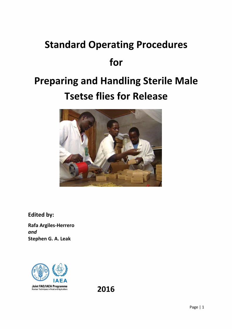
Standard Operating Procedures
for
Preparing and Handling Sterile Male
Tsetse flies for Release
Edited by:
Rafa Argiles-Herrero and Stephen G. A. Leak
2016
Page | 2
Contents
1. Introduction .................................................................................................................................... 4
2. Feeding procedures for male tsetse flies ........................................................................................ 5
3. Marking of the males on emergence with fluorescent dye ............................................................ 7
4. Separation of the females from the males ................................................................................... 10
5. Chilling and irradiation of the males ............................................................................................. 13
6. Packing the sterile males into the boxes to be used for release .................................................. 15
7. Shipping the boxed, sterile males to the airport for delivery to the release aircraft ................... 16
8. Aerial releases of sterile males ..................................................................................................... 18
9. Quality control of the released flies .............................................................................................. 21
Annex 1 ................................................................................................................................................. 22
Optimal Environmental conditions for tsetse flies ............................................................................... 23
Annex 2 ................................................................................................................................................. 24
Cage densities for release males........................................................................................................... 24
Annex 3 ................................................................................................................................................. 25
Safety Operation Procedures for using irradiators ............................................................................... 25
for sterilisation of tsetse ....................................................................................................................... 25
Procedures in the Event of a Fault ................................................................................................ 27
Annex 4 ................................................................................................................................................. 29
Manual for the Quality Control (QC) database ..................................................................................... 29
Annex 5 ................................................................................................................................................. 33
List of suppliers of equipment .............................................................................................................. 33
Glossary and Abbreviations .................................................................................................................. 35

Page | 3
Disclaimer: The mention of names of specific companies or products (whether or not
indicated as registered) does not imply any intention to infringe proprietary rights, nor should
it be construed as an endorsement or recommendation on the part of the FAO/IAEA.
Page | 4
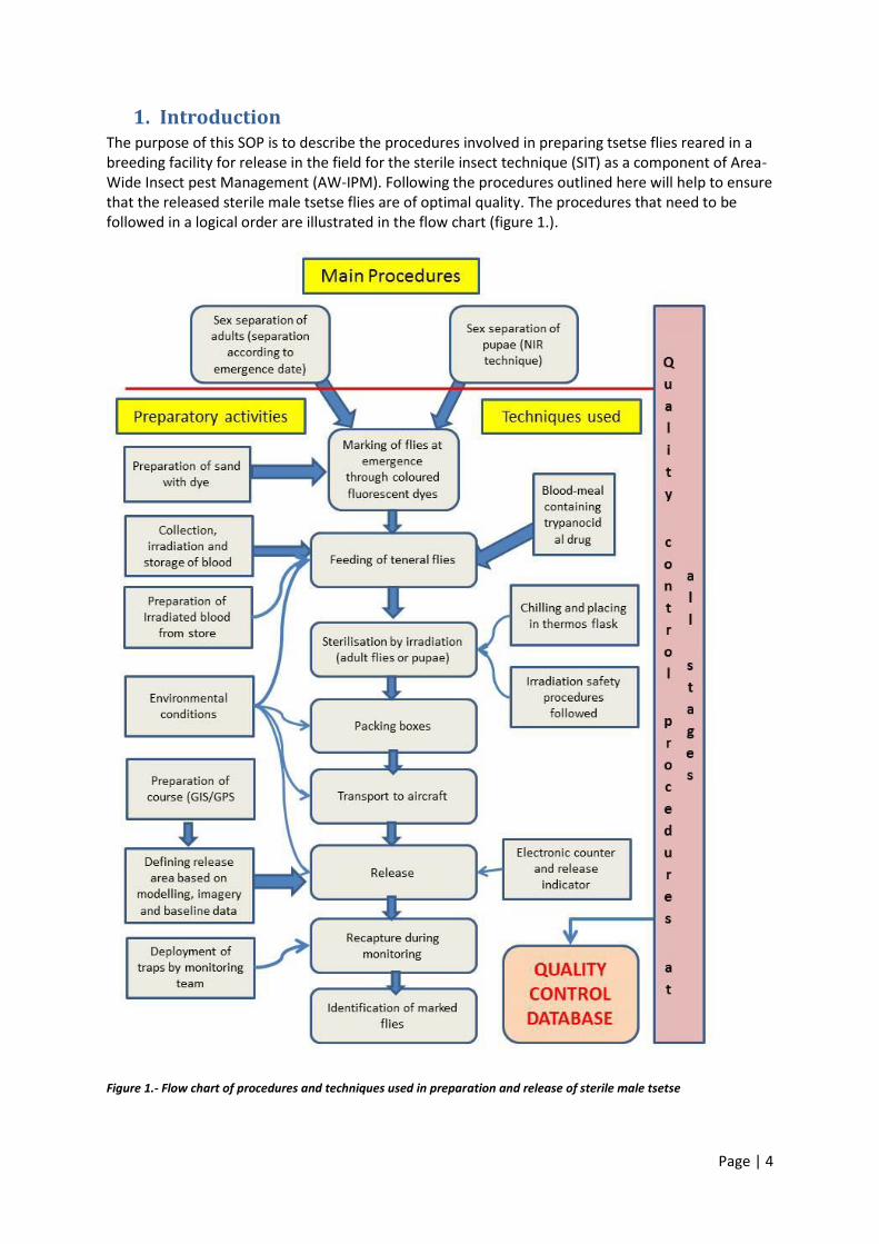
1. Introduction The purpose of this SOP is to describe the procedures involved in preparing tsetse flies reared in a breeding facility for release in the field for the sterile insect technique (SIT) as a component of Area-Wide Insect pest Management (AW-IPM). Following the procedures outlined here will help to ensure that the released sterile male tsetse flies are of optimal quality. The procedures that need to be followed in a logical order are illustrated in the flow chart (figure 1.).
Figure 1.- Flow chart of procedures and techniques used in preparation and release of sterile male tsetse
Page | 5
2. Feeding procedures for male tsetse flies Teneral flies (newly emerged flies that have not yet taken their first blood meal) must be given the opportunity to feed every day during the first week after emergence. After sex separation, males intended for release will be kept for 4 to 10 days before being released. The age of males at release is a compromise between feeding to produce stronger flies with better performance once released and avoiding increased losses due to mortality in the period before release. All tsetse flies can transmit trypanosomes, including the released sterile males. The probability of flies becoming infected decreases rapidly with age over the first few days as the newly emerged adults feed. It is, therefore, important to ensure that every released sterile male fly has been fed at least twice, to reduce the risk of the released flies causing additional disease. The effect of this initial feeding can be enhanced by adding a trypanocidal drug. Addition of trypanocidal drugs to blood meals of reared tsetse intended to be released for SIT has been shown to significantly reduce the establishment of infections in tsetse flies after they have subsequently taken a blood-meal from a host infected with trypanosomes. Flies should be given the opportunity to feed at least twice (at 24h and 48h post-emergence) with irradiated bovine blood containing the prophylactic trypanocidal drug, isometamidium chloride, (sold under the commercial names of
Trypamidium®, Samorin® or Veridium®) at a dose of 10-15μg per ml before release. A dose of 12-
15μg per ml of blood has been found to completely suppress trypanosome infections (T. vivax, T. congolense and T. b. brucei) from developing in G. morsitans centralis fed on an infected blood-meal given 10 days after the treated blood-meal and examined by dissection and microscopic examination of the tsetse labra, hypopharynxes and salivary glands. A dose of 12-15μg was therefore recommended for treatment of sterile male tsetse being released for SIT. Trypanosoma vivax has the shortest development cycle within the tsetse fly, lasting from 5 to 14 days depending on temperature, and would therefore theoretically be the most likely to develop in a tsetse fly after the prophylactic effect of the treated blood-meal has worn off and before the released sterile male fly has died from natural mortality. Trypanosoma brucei has the longest developmental cycle in the tsetse fly (~30 days) and would therefore be the least likely trypanosome species to be able to complete its cycle and be transmitted to a host by a sterile male fly. The average survival of the sterile males in the field after releases is less than two weeks, so the likelihood of cyclical transmission of trypanosomes by sterile male tsetse fed on a treated blood-meal is very low indeed, although there may be a very small possibility of mechanical transmission similar to that from biting flies but this almost impossible to demonstrate under field conditions. Dosage and administration of isometamidium chloride The trypanocidal drug, isometamidium chloride, is safe and effective when fed to tsetse flies at a concentration of 10-15μg per ml of blood. Prepare blood containing 10μg isometamidium chloride per ml and put this in a standard feeding tray on a heating plate. The male flies can be fed through the holes in the release boxes.
Page | 6
Environmental conditions Environmental conditions of the holding room for release males are the same as for the colony room. Values for different species can be found in Annex 1.
Figure 2.- Example of a commercial formulation of Isometamidium
Page | 7
3. Marking of the males on emergence with fluorescent dye
Fluorescent dyes and colours
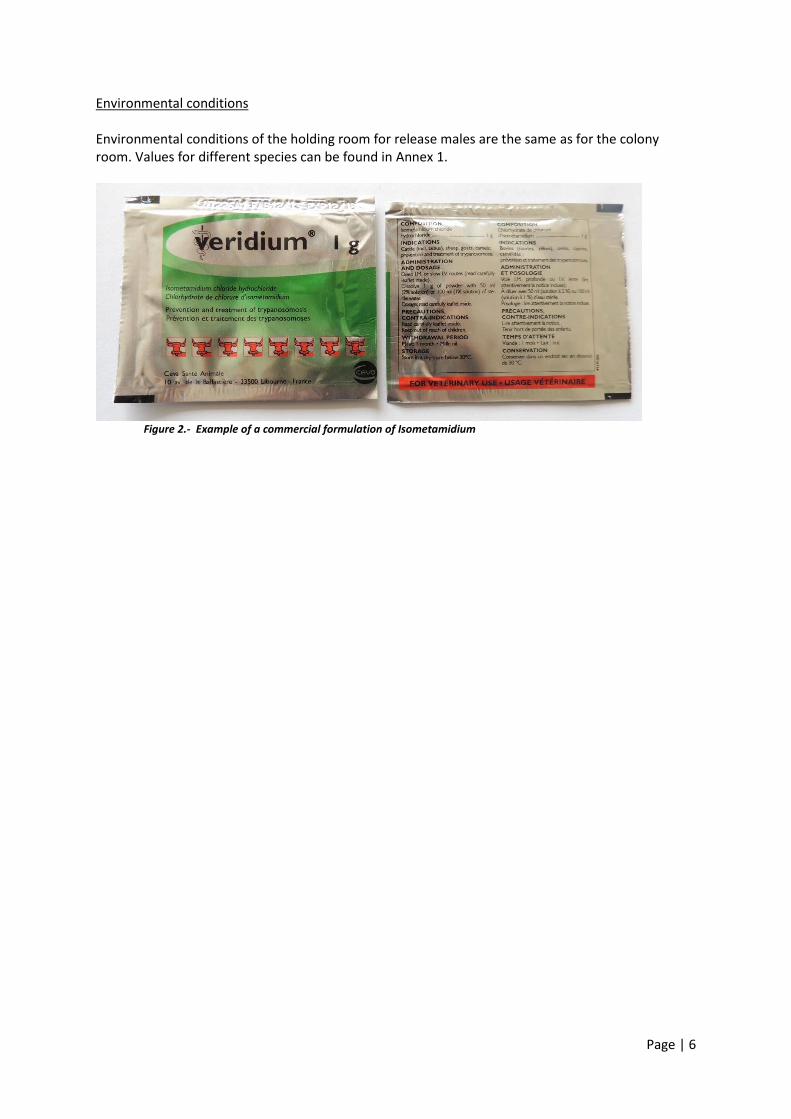
DayGlo® fluorescent dyes are available in many colours such as red, orange, pink, yellow, green or
blue. These dyes fluoresce (produce coloured light) when exposed to ultra-violet light (UV). Under darkened conditions, a single grain of dye can be seen under UV light. Single colours or simple mixtures of colours can be used to distinguish different day’s releases so that the age of flies caught in the field can be estimated.
Figure 3. Tsetse flies dyed with different colours
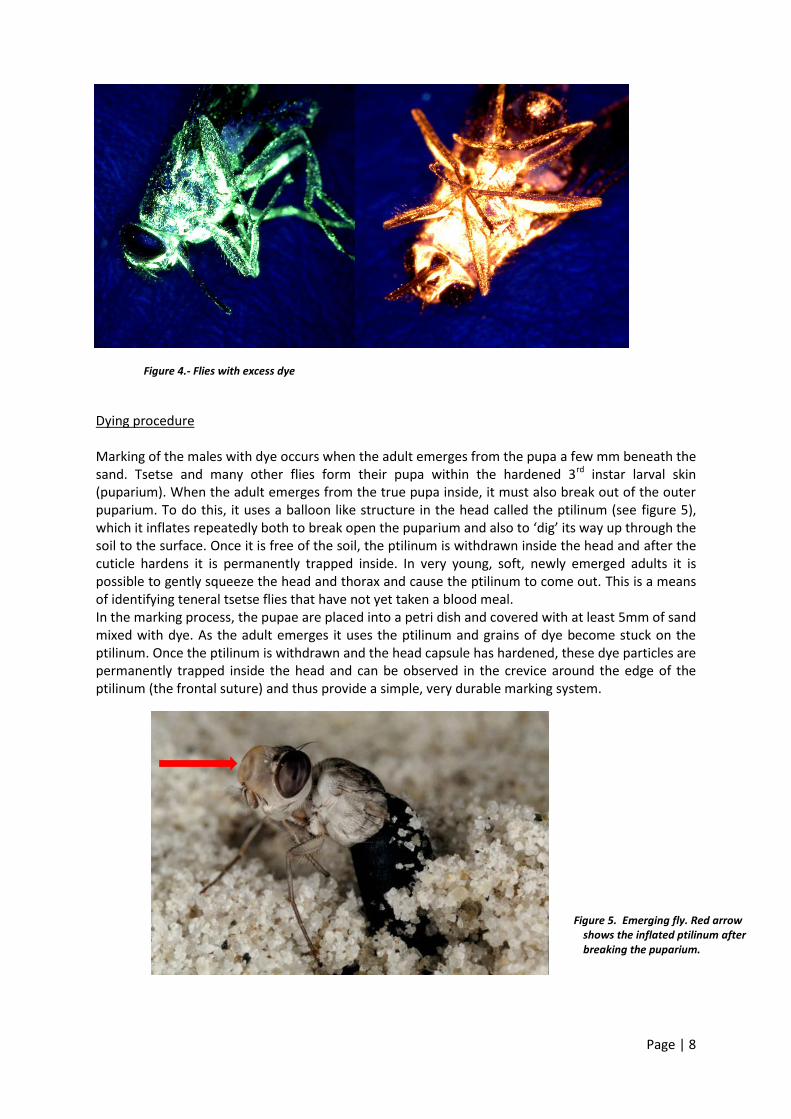
Age estimation In order to be able to estimate the age of the sterile males caught in the field monitoring traps, it is recommended that the same sequence of dye colours is always used when dying the males before releases. For example, males to be released on week one will be dyed with a pink colour, males to be released on week two will be dyed with yellow colour and males to be released on week three will be dyed with blue colour. The same pattern will be repeated every three weeks. Since the lifespan of released males in the field usually doesn’t exceed three weeks, a pattern of three colours will be enough to allow proper age estimation. When selecting the colour pattern, take into consideration that pink, red and orange can look similar. Similarly, yellow and green can sometimes be difficult to distinguish. Preparation of the dyed sand The dye is mixed with sand as a carrier and the males are allowed to emerge through the sand/dye mixture. The sand must be washed, dried and sieved. Sand must be thoroughly mixed with dye at a rate of 0.25% to 0.50% (up to 1%). The exact rate will depend on the type of sand. Tests should be conducted to define the exact dye concentration in the mix and avoid over dyed flies as shown in the figure 4. Excess of dye will damage the insects by obstructing the spiracles.
Page | 8
Figure 4.- Flies with excess dye
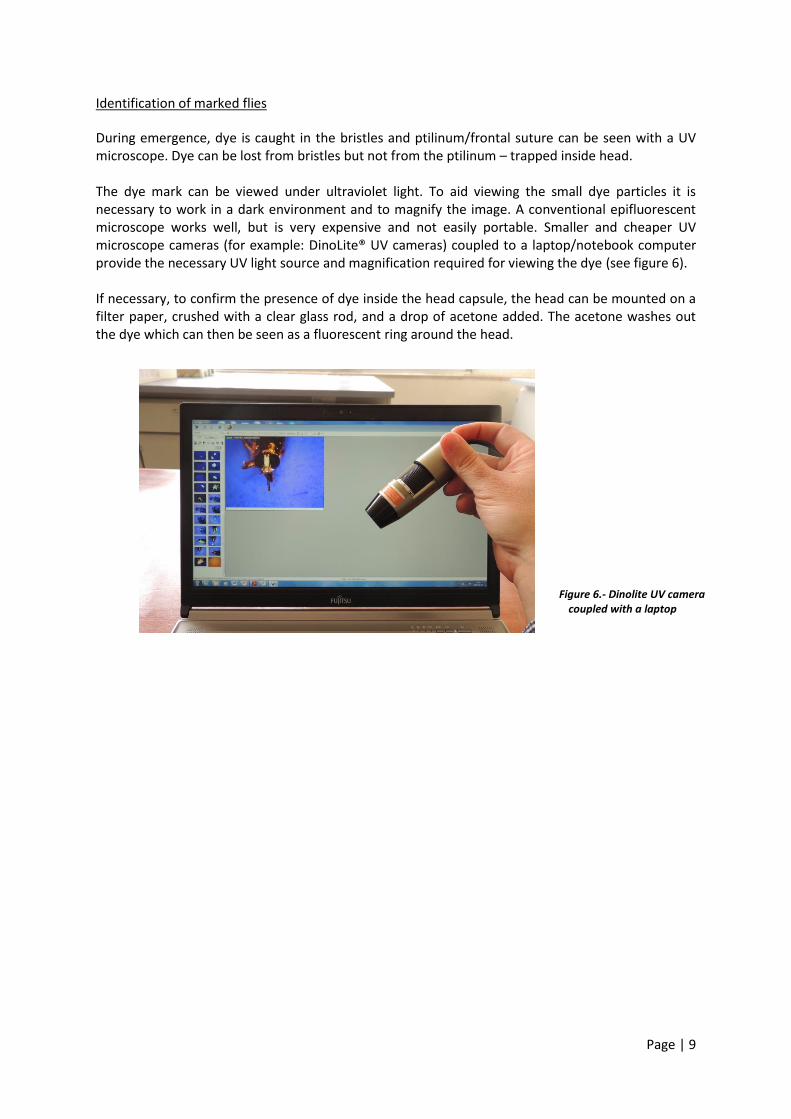
Dying procedure Marking of the males with dye occurs when the adult emerges from the pupa a few mm beneath the sand. Tsetse and many other flies form their pupa within the hardened 3rd instar larval skin (puparium). When the adult emerges from the true pupa inside, it must also break out of the outer puparium. To do this, it uses a balloon like structure in the head called the ptilinum (see figure 5), which it inflates repeatedly both to break open the puparium and also to ‘dig’ its way up through the soil to the surface. Once it is free of the soil, the ptilinum is withdrawn inside the head and after the cuticle hardens it is permanently trapped inside. In very young, soft, newly emerged adults it is possible to gently squeeze the head and thorax and cause the ptilinum to come out. This is a means of identifying teneral tsetse flies that have not yet taken a blood meal. In the marking process, the pupae are placed into a petri dish and covered with at least 5mm of sand mixed with dye. As the adult emerges it uses the ptilinum and grains of dye become stuck on the ptilinum. Once the ptilinum is withdrawn and the head capsule has hardened, these dye particles are permanently trapped inside the head and can be observed in the crevice around the edge of the ptilinum (the frontal suture) and thus provide a simple, very durable marking system.
Figure 5. Emerging fly. Red arrow shows the inflated ptilinum after breaking the puparium.
Page | 9
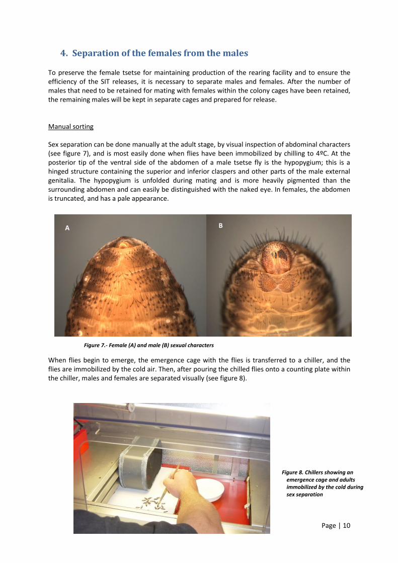
Identification of marked flies During emergence, dye is caught in the bristles and ptilinum/frontal suture can be seen with a UV microscope. Dye can be lost from bristles but not from the ptilinum – trapped inside head. The dye mark can be viewed under ultraviolet light. To aid viewing the small dye particles it is necessary to work in a dark environment and to magnify the image. A conventional epifluorescent microscope works well, but is very expensive and not easily portable. Smaller and cheaper UV microscope cameras (for example: DinoLite® UV cameras) coupled to a laptop/notebook computer provide the necessary UV light source and magnification required for viewing the dye (see figure 6). If necessary, to confirm the presence of dye inside the head capsule, the head can be mounted on a filter paper, crushed with a clear glass rod, and a drop of acetone added. The acetone washes out the dye which can then be seen as a fluorescent ring around the head.
Figure 6.- Dinolite UV camera coupled with a laptop
Page | 10
4. Separation of the females from the males
To preserve the female tsetse for maintaining production of the rearing facility and to ensure the efficiency of the SIT releases, it is necessary to separate males and females. After the number of males that need to be retained for mating with females within the colony cages have been retained, the remaining males will be kept in separate cages and prepared for release. Manual sorting Sex separation can be done manually at the adult stage, by visual inspection of abdominal characters (see figure 7), and is most easily done when flies have been immobilized by chilling to 4ºC. At the posterior tip of the ventral side of the abdomen of a male tsetse fly is the hypopygium; this is a hinged structure containing the superior and inferior claspers and other parts of the male external genitalia. The hypopygium is unfolded during mating and is more heavily pigmented than the surrounding abdomen and can easily be distinguished with the naked eye. In females, the abdomen is truncated, and has a pale appearance.
When flies begin to emerge, the emergence cage with the flies is transferred to a chiller, and the flies are immobilized by the cold air. Then, after pouring the chilled flies onto a counting plate within the chiller, males and females are separated visually (see figure 8).
Figure 7.- Female (A) and male (B) sexual characters
A B
Figure 8. Chillers showing an emergence cage and adults immobilized by the cold during sex separation
Page | 11
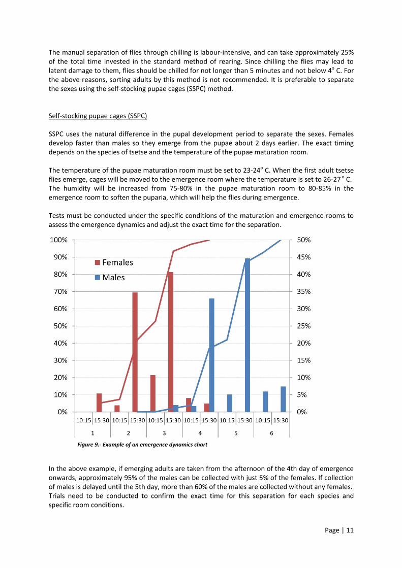
The manual separation of flies through chilling is labour-intensive, and can take approximately 25% of the total time invested in the standard method of rearing. Since chilling the flies may lead to latent damage to them, flies should be chilled for not longer than 5 minutes and not below 4o C. For the above reasons, sorting adults by this method is not recommended. It is preferable to separate the sexes using the self-stocking pupae cages (SSPC) method. Self-stocking pupae cages (SSPC) SSPC uses the natural difference in the pupal development period to separate the sexes. Females develop faster than males so they emerge from the pupae about 2 days earlier. The exact timing depends on the species of tsetse and the temperature of the pupae maturation room. The temperature of the pupae maturation room must be set to 23-24o C. When the first adult tsetse flies emerge, cages will be moved to the emergence room where the temperature is set to 26-27 o C. The humidity will be increased from 75-80% in the pupae maturation room to 80-85% in the emergence room to soften the puparia, which will help the flies during emergence. Tests must be conducted under the specific conditions of the maturation and emergence rooms to assess the emergence dynamics and adjust the exact time for the separation.
Figure 9.- Example of an emergence dynamics chart
In the above example, if emerging adults are taken from the afternoon of the 4th day of emergence onwards, approximately 95% of the males can be collected with just 5% of the females. If collection of males is delayed until the 5th day, more than 60% of the males are collected without any females. Trials need to be conducted to confirm the exact time for this separation for each species and specific room conditions.
Page | 12
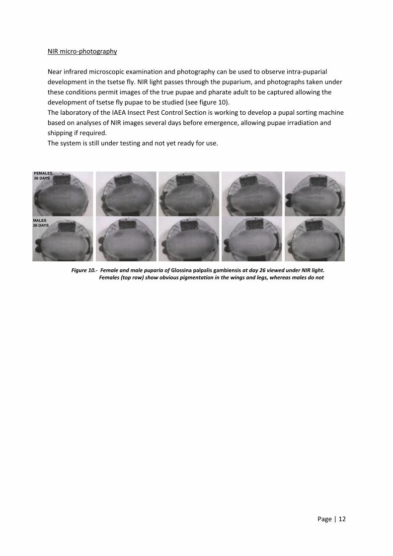
NIR micro-photography
Near infrared microscopic examination and photography can be used to observe intra-puparial
development in the tsetse fly. NIR light passes through the puparium, and photographs taken under
these conditions permit images of the true pupae and pharate adult to be captured allowing the
development of tsetse fly pupae to be studied (see figure 10).
The laboratory of the IAEA Insect Pest Control Section is working to develop a pupal sorting machine
based on analyses of NIR images several days before emergence, allowing pupae irradiation and
shipping if required.
The system is still under testing and not yet ready for use.
Figure 10.- Female and male puparia of Glossina palpalis gambiensis at day 26 viewed under NIR light. Females (top row) show obvious pigmentation in the wings and legs, whereas males do not
Page | 13
5. Chilling and irradiation of the males
Irradiation of adults
The day before the release, the males will be irradiated. For this, the adult males are chilled to
immobilize them. To keep them chilled during irradiation and packing they are put into a Thermos
flask, which must be well chilled (but not frozen!) in the chiller first.
Depending on the size of the Thermos flask and of the tsetse species, about 4,000 males can be put
in at one time. The flask should not be more than half filled to prevent damage to the males. The
irradiation and packing should be carried out quickly so as to keep the time the males are chilled as
short as reasonably possible.
The males are sterilized (irradiated) in the irradiator inside the Thermos flask. The irradiation dose is
species specific for tsetse but will generally be in the range 110-120Gy.
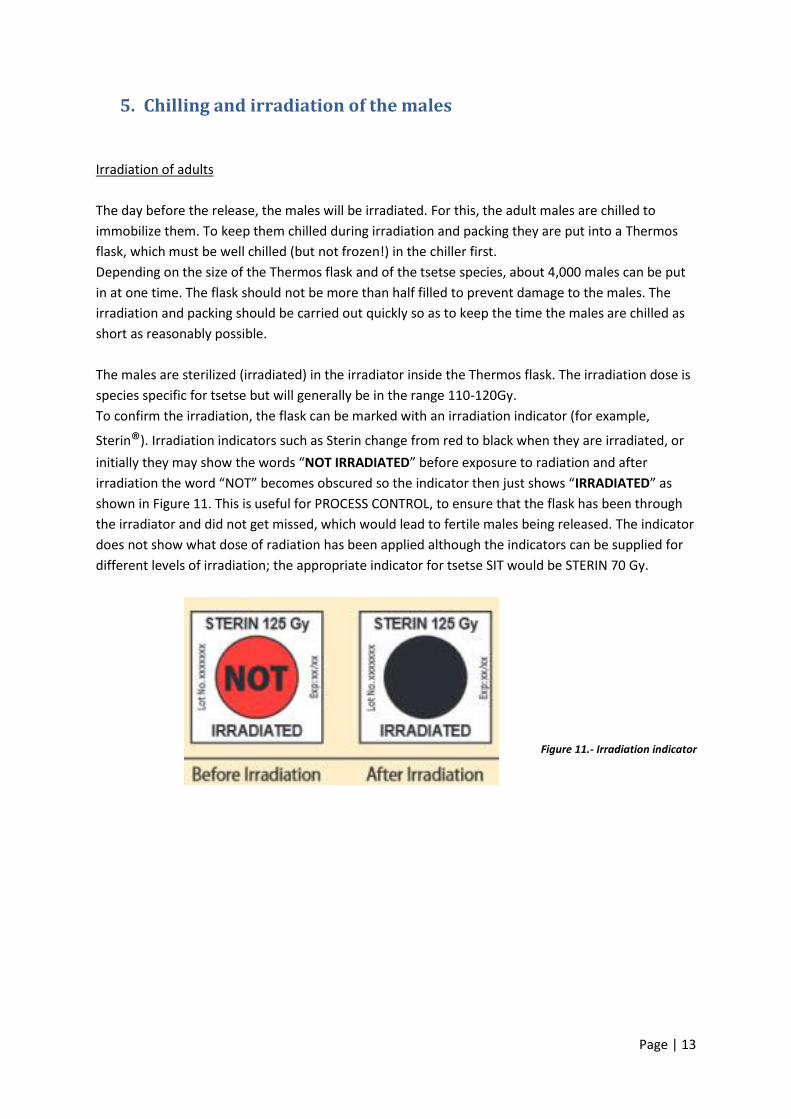
To confirm the irradiation, the flask can be marked with an irradiation indicator (for example,
Sterin®). Irradiation indicators such as Sterin change from red to black when they are irradiated, or
initially they may show the words “NOT IRRADIATED” before exposure to radiation and after
irradiation the word “NOT” becomes obscured so the indicator then just shows “IRRADIATED” as
shown in Figure 11. This is useful for PROCESS CONTROL, to ensure that the flask has been through
the irradiator and did not get missed, which would lead to fertile males being released. The indicator
does not show what dose of radiation has been applied although the indicators can be supplied for
different levels of irradiation; the appropriate indicator for tsetse SIT would be STERIN 70 Gy.
Figure 11.- Irradiation indicator
Page | 14
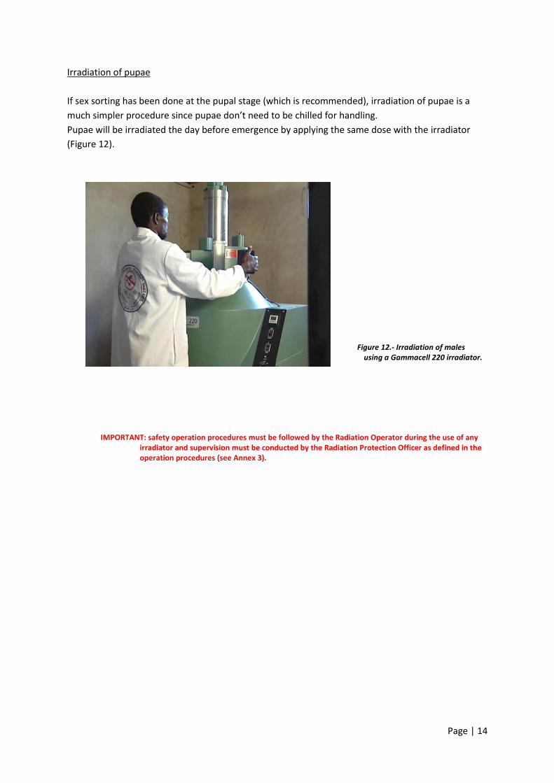
Irradiation of pupae
If sex sorting has been done at the pupal stage (which is recommended), irradiation of pupae is a
much simpler procedure since pupae don’t need to be chilled for handling.
Pupae will be irradiated the day before emergence by applying the same dose with the irradiator
(Figure 12).
IMPORTANT: safety operation procedures must be followed by the Radiation Operator during the use of any irradiator and supervision must be conducted by the Radiation Protection Officer as defined in the operation procedures (see Annex 3).
Figure 12.- Irradiation of males using a Gammacell 220 irradiator.
Page | 15
6. Packing the sterile males into the boxes to be used for release
The irradiated tsetse flies in the Thermos flask must then be packed into the release carton boxes.
The boxes must be prepared for filling in advance. The flies should be measured volumetrically as it
is much too slow to count them individually.
A suitable measure needs to be identified. A small container, for example the screw top off a bottle,
is suitable. The measure needs to be calibrated by measuring several samples of flies and counting
the flies. This should be repeated several times, with different people measuring the flies each time.
When a suitable container is found, it can be used to fill the boxes.
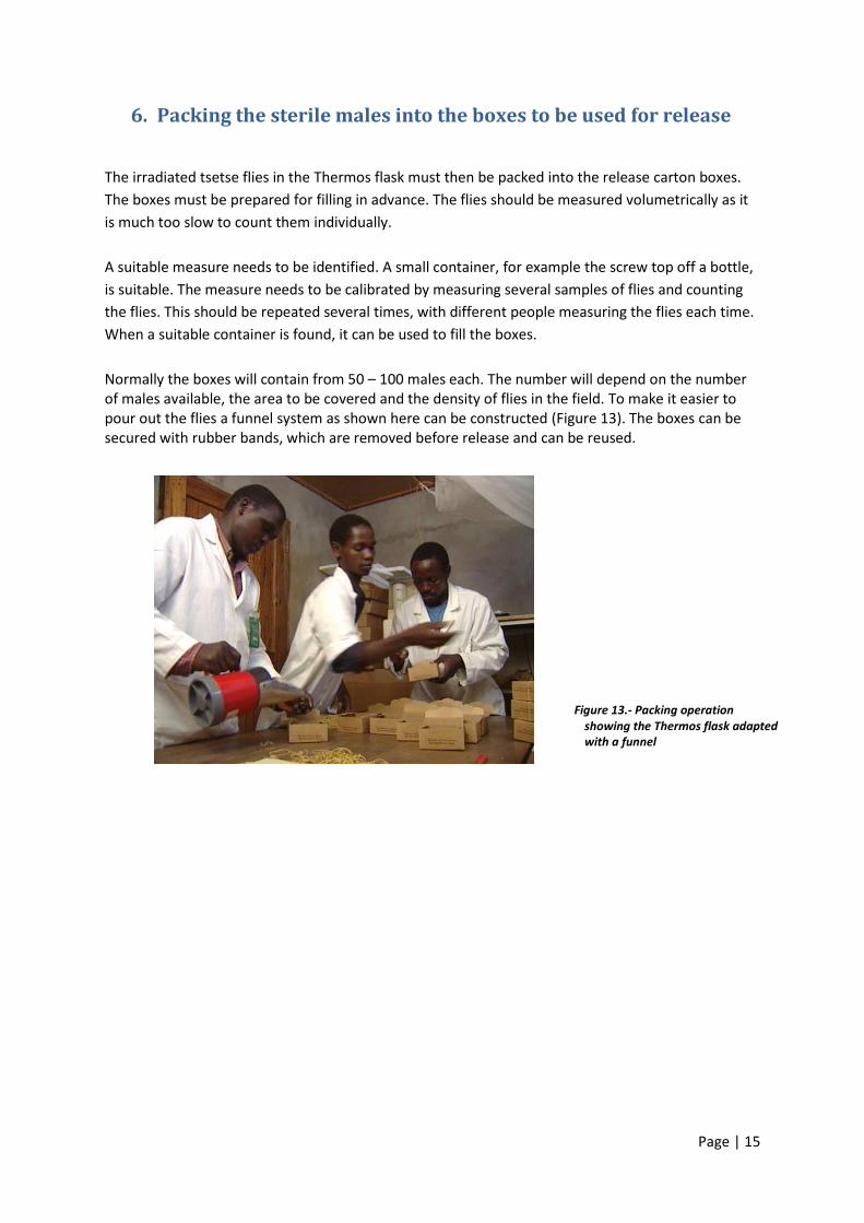
Normally the boxes will contain from 50 – 100 males each. The number will depend on the number of males available, the area to be covered and the density of flies in the field. To make it easier to pour out the flies a funnel system as shown here can be constructed (Figure 13). The boxes can be secured with rubber bands, which are removed before release and can be reused.
Figure 13.- Packing operation showing the Thermos flask adapted with a funnel
Page | 16
7. Shipping the boxed, sterile males to the airport for delivery to
the release aircraft
The carton boxes containing the sterile male tsetse flies are small and light and must therefore be
handled with care, both to avoid damage to the flies themselves and to prevent any escapes before
the point of release.
For convenience of handling, the boxes may be stacked upon thin plywood boards. A new board
should be placed between each two layers of boxes to stabilize them. The number of layers of boxes
should be restricted so that the weight does not damage the lowest level of boxes and compact the
flies and so that the stack can be conveniently placed inside the vehicle that will be used for
transporting them to the aircraft. Bind the stack together to prevent boxes falling down, by means of
a large rubber band, for example using a strip cut from a car inner tube. However care must be taken
to ensure that this rubber band does not squeeze the boxes excessively, causing damage to them or
creating openings through which flies can escape.
The stacks of boxes may then be transported to the airport for delivery to the release aircraft.
Ensure that the boxes in the vehicle used to transport them are adequately protected from exposure
to sun, rain, dust etc. and that the vehicle has not previously been used to transport insecticides or
other toxic substances that could have contaminated it.
In the tropical countries of Africa, where tsetse flies live, airports are likely to be hot and vehicles in
traffic could be subject to high temperatures that could kill tsetse within the release boxes. Data
loggers should be placed with the stacks of cartons during transportation to record maximum and
minimum temperatures during transport. Air-conditioned vehicles should be used if ambient
temperatures are likely to result in overheating of the sterile male tsetse.
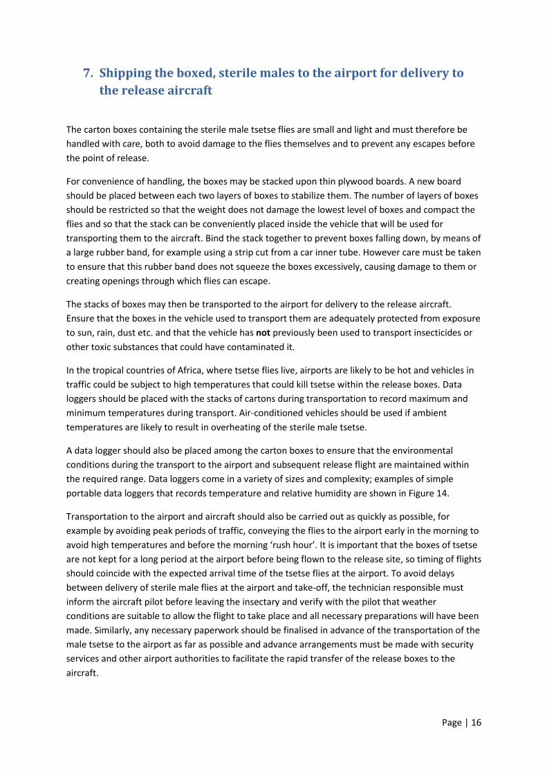
A data logger should also be placed among the carton boxes to ensure that the environmental
conditions during the transport to the airport and subsequent release flight are maintained within
the required range. Data loggers come in a variety of sizes and complexity; examples of simple
portable data loggers that records temperature and relative humidity are shown in Figure 14.
Transportation to the airport and aircraft should also be carried out as quickly as possible, for
example by avoiding peak periods of traffic, conveying the flies to the airport early in the morning to
avoid high temperatures and before the morning ‘rush hour’. It is important that the boxes of tsetse
are not kept for a long period at the airport before being flown to the release site, so timing of flights
should coincide with the expected arrival time of the tsetse flies at the airport. To avoid delays
between delivery of sterile male flies at the airport and take-off, the technician responsible must
inform the aircraft pilot before leaving the insectary and verify with the pilot that weather
conditions are suitable to allow the flight to take place and all necessary preparations will have been
made. Similarly, any necessary paperwork should be finalised in advance of the transportation of the
male tsetse to the airport as far as possible and advance arrangements must be made with security
services and other airport authorities to facilitate the rapid transfer of the release boxes to the
aircraft.
Page | 17
Figure 14.- Example of a data logger that can be connected to the USB port of a PC.
Page | 18
8. Aerial releases of sterile males
Once the aircraft reaches the release area, the pilot will fly a predetermined course, set using the
project’s GIS system. The path of the plane is controlled by a GPS navigation system. After removing
the rubber band(s), the boxes are released one at a time through a chute fixed in the bottom
fuselage of the aircraft.
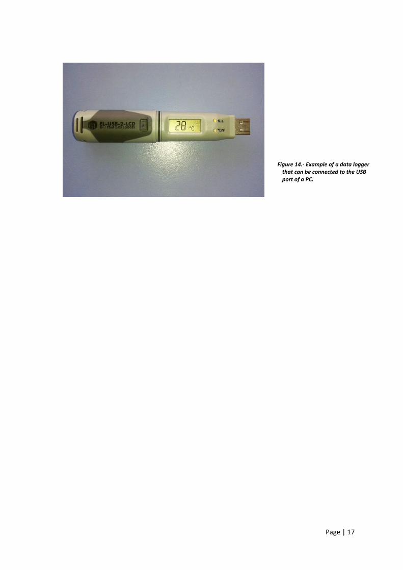
A light signal in the electronic counter (see figure 15) indicates to the release staff the exact moment
to drop the box in order to maintain a predefined release interval between box drops. The release
interval in metres will have been set in advance into the electronic counter. As the aircraft advances,
the distance to the next release point is shown in the display of the counter and a set of LEDs blink
when it is time for the next drop.
The electronic counter saves a digital file recording the position at which each box has been dropped
as detected by a sensor at the bottom end of the chute. The file can be imported into GIS software
for later analysis of the quality of the flight.
Defining the release area
In order to define the release area, it is advisable to develop a predicted distribution map of the
Project area with the help of specialized modelling software (MAXENT, R). This software produces a
predicted distribution layer modelling the range of a species, based on presence and absence data
obtained from baseline entomological data collection, combined with data from satellite imagery
such as vegetation index elevation, precipitation and ground temperature that can be freely
downloaded from the internet (e.g. MODIS satellite imagery).
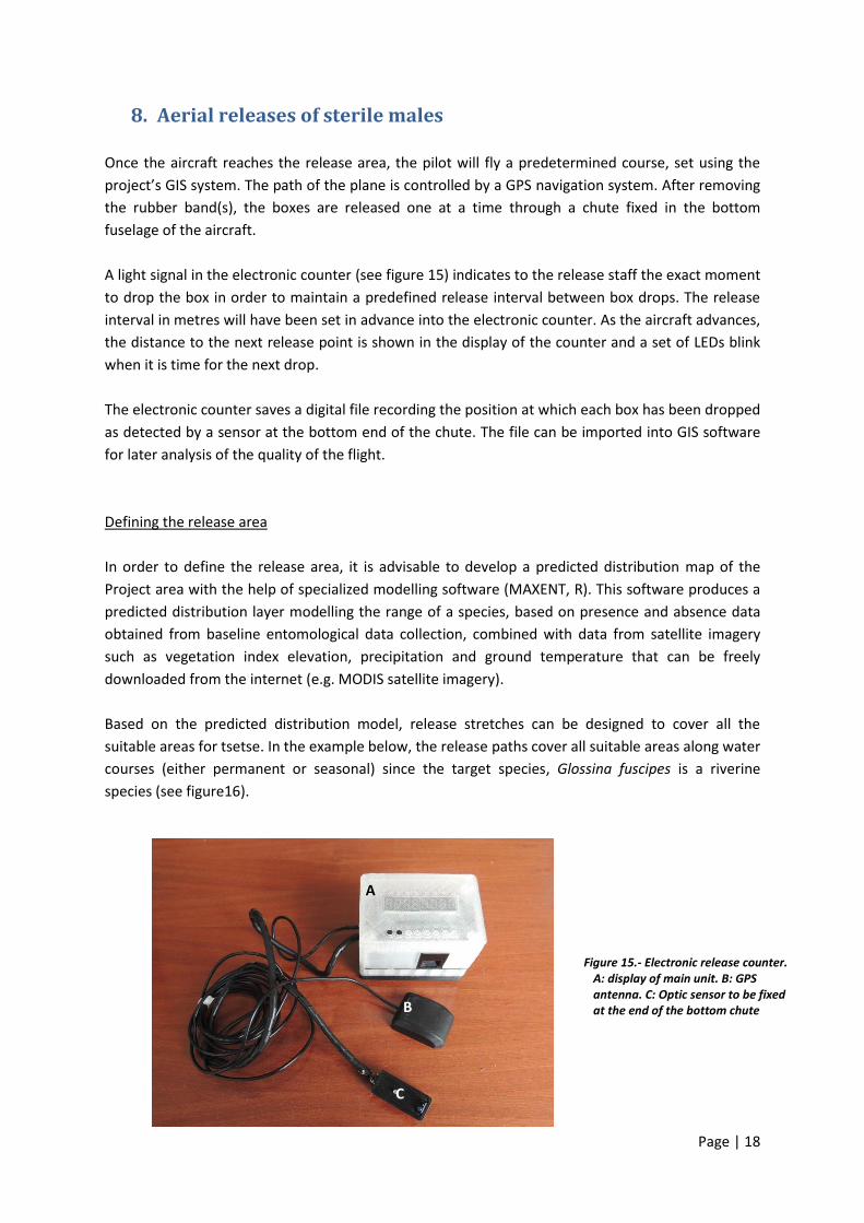
Based on the predicted distribution model, release stretches can be designed to cover all the
suitable areas for tsetse. In the example below, the release paths cover all suitable areas along water
courses (either permanent or seasonal) since the target species, Glossina fuscipes is a riverine
species (see figure16).
B
C
A
Figure 15.- Electronic release counter. A: display of main unit. B: GPS antenna. C: Optic sensor to be fixed at the end of the bottom chute
Page | 19
Figure 16.- Map with the release sections covering the predicted distribution area in the Deme eradication project
Page | 20
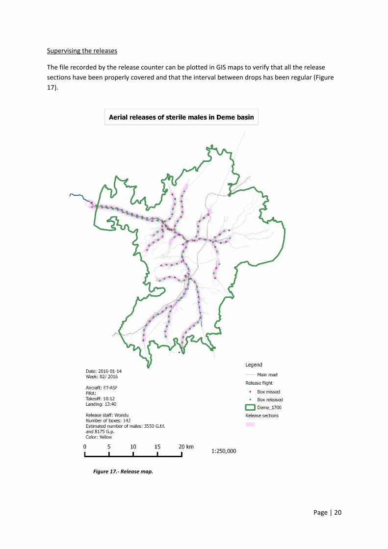
Supervising the releases
The file recorded by the release counter can be plotted in GIS maps to verify that all the release
sections have been properly covered and that the interval between drops has been regular (Figure
17).
Figure 17.- Release map.
Page | 21
9. Quality control of the released flies The purpose of this procedure is to assess the flight ability, mortality and longevity of the sterile male tsetse before and after the release and is carried out as follows.
- Collect one box of sterile males before leaving the insectary. A second box will be sampled from the stack of boxes as they are being loaded onto the release plane. The release crew must keep two more boxes to return to the insectary after the release. Each QC parameter is recorded for the boxes of males taken before the release and for the boxes brought back from the release.
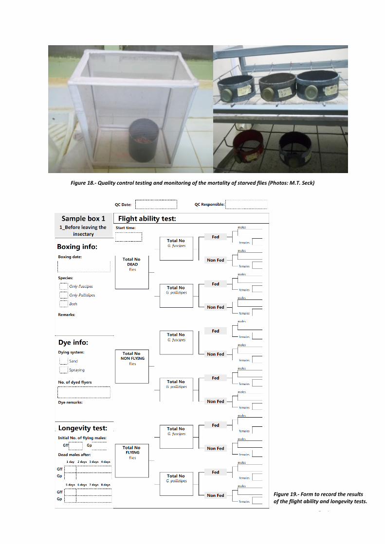
- Each box is chilled for five minutes and carefully opened inside a netting cage. and the chilled male flies are placed into an open, vertical pipe (figure 18). This pipe is coated on the inside with talcum powder so that the flies can only escape by flying rather than by crawling or jumping. The cage is left in normal light conditions for 15 minutes during which the flies will warm up. Then, the pipe is covered with a lid.
- Chill the complete cage to immobilize the flies and remove the pipe from the inside of the cage.
- Count the number of flies in the cage, record the number of males and females and for each
sex record also the number of fed and non-fed flies. The flies in the cage will be considered fliers
- Open the lid of the pipe and count the dead flies. As in the previous case, record the number of males and females and for each sex record the number of fed and non-fed flies.
- After discarding the dead flies, count the remaining flies inside the pipe and record males
and females and their feeding status. These flies will be recorded as non-fliers.
- Calculate:
The total number of flies in the box and express as a % of the target number (filling accuracy %)
The total number of females and express as a % of total number of flies (sexing error %)
The total number of male fliers and express as a % of total live males (fliers %)
The number of dead flies and express as a % of total number of flies (mortality %)
The number of fed flies and express as % of flies (feeding rate %) A second procedure can be carried out to assess the longevity of the flies that are able to fly out of the PVC pipe. After counting and sexing these ‘flyers’ they are returned to a normal colony cage where they will be kept without feeding. The survivors will be counted every day and the survival rate under feeding stress will be calculated every day. The average longevity of the flies will also be calculated.
Figure 19 shows a form that can be used to record the results of the flight ability and longevity tests.
Page | 22
Figure 18.- Quality control testing and monitoring of the mortality of starved flies (Photos: M.T. Seck)
Figure 19.- Form to record the results of the flight ability and longevity tests.
Page | 23
Annex 1
Optimal Environmental conditions for tsetse flies
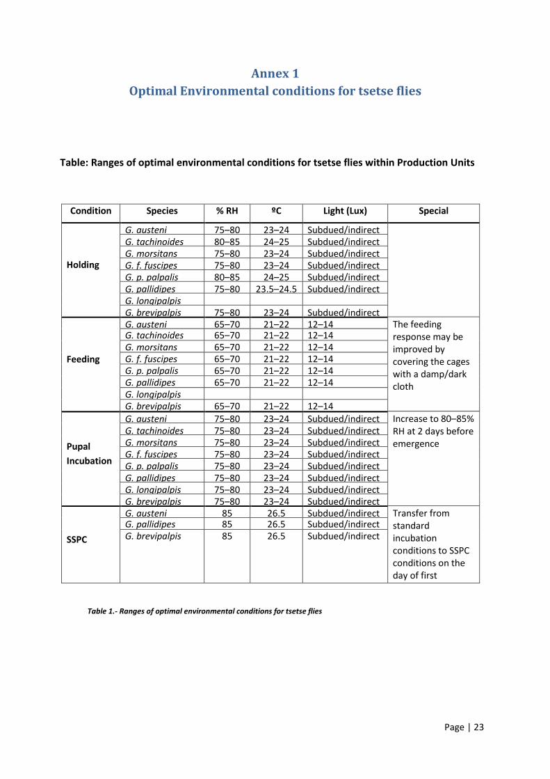
Table: Ranges of optimal environmental conditions for tsetse flies within Production Units
Condition Species % RH ºC Light (Lux) Special
Holding
G. austeni 75–80 23–24 Subdued/indirect G. tachinoides 80–85 24–25 Subdued/indirect G. morsitans 75–80 23–24 Subdued/indirect G. f. fuscipes 75–80 23–24 Subdued/indirect G. p. palpalis 80–85 24–25 Subdued/indirect G. pallidipes 75–80 23.5–24.5 Subdued/indirect G. longipalpis G. brevipalpis 75–80 23–24 Subdued/indirect
Feeding
G. austeni 65–70 21–22 12–14 The feeding response may be improved by covering the cages with a damp/dark cloth
G. tachinoides 65–70 21–22 12–14 G. morsitans 65–70 21–22 12–14 G. f. fuscipes 65–70 21–22 12–14 G. p. palpalis 65–70 21–22 12–14 G. pallidipes 65–70 21–22 12–14 G. longipalpis G. brevipalpis 65–70 21–22 12–14
Pupal
Incubation
G. austeni 75–80 23–24 Subdued/indirect Increase to 80–85% RH at 2 days before emergence
G. tachinoides 75–80 23–24 Subdued/indirect G. morsitans 75–80 23–24 Subdued/indirect G. f. fuscipes 75–80 23–24 Subdued/indirect G. p. palpalis 75–80 23–24 Subdued/indirect G. pallidipes 75–80 23–24 Subdued/indirect G. longipalpis 75–80 23–24 Subdued/indirect G. brevipalpis 75–80 23–24 Subdued/indirect
SSPC
G. austeni 85 26.5 Subdued/indirect Transfer from standard incubation conditions to SSPC conditions on the day of first emergence
G. pallidipes 85 26.5 Subdued/indirect G. brevipalpis 85 26.5 Subdued/indirect
Table 1.- Ranges of optimal environmental conditions for tsetse flies
Page | 24
Annex 2
Cage densities for release males
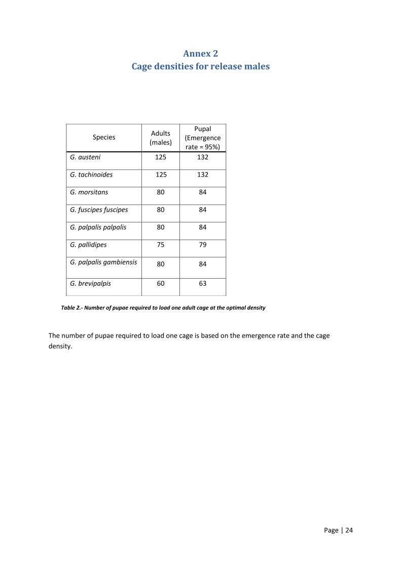
The number of pupae required to load one cage is based on the emergence rate and the cage
density.
Species Adults (males)
Pupal (Emergence rate = 95%)
G. austeni 125 132
G. tachinoides 125 132
G. morsitans 80 84
G. fuscipes fuscipes 80 84
G. palpalis palpalis 80 84
G. pallidipes 75 79
G. palpalis gambiensis
80 84
G. brevipalpis 60 63
Table 2.- Number of pupae required to load one adult cage at the optimal density
Page | 25
Annex 3
Safety Operation Procedures for using irradiators
for sterilisation of tsetse
Introduction
These safety instructions relate to the operation of irradiators for sterilising tsetse prior to their
release in SIT programmes. Some of the procedures given here are specific for the Gammacell GC220
but similar procedures must be adopted for other models of irradiator and should be followed in the
event of any malfunction. More detailed Standard Operating Procedures are provided in a separate
SOP produced by IAEA1.
Description of the Equipment
The irradiator will normally be self-shielded. The radioactive source is in the form of a number of
pencils arranged in a cylindrical cage inside a lead shield. In the case of the Gammacell 220, samples
for irradiation are placed in a chamber that can move vertically from the load position to the
irradiate position without exposing the source. The sample chamber is closed by a metal door with a
sliding catch and shielded by two collar doors. The chamber door and collar doors operate safety
switches that prevent the operation of the equipment if they are not correctly closed.
Operation of the GC220 is from a control panel on the right-hand side of the machine. The control
panel houses a timer, manual/automatic selector switch, down/up operating switch and on/off key
switch.
External Radiation Field
The irradiator will normally be shielded with lead on all sides. As a result the radiation field is
attenuated to safe levels outside the machine. The highest measured dose rate is expected to be
directly in front of the machine.
Due to the external dose rate the room containing the irradiator and the area outside the door are
controlled areas.
Safety procedures and equipment
No one other than authorised users of the irradiator, with appropriate dosimeters, may enter the
controlled area without the express permission of the Registered User and the Radiation Protection
Officer (RPO), under the conditions specified by the RPO.
1 *E. Opiyo & A.G. Parker. 2006. Standard Operating Procedures for Mass-rearing tsetse. FAO-IAEA Joint Division
Page | 26
Operators of the irradiator are required to:
1. Wear both a TLD and an electronic alarming dosimeter whilst in the controlled area.
2. Measure the external field using a suitable radiation monitor (e.g. Mini Rad 1000 or
RadScout) before starting work.
3. Minimize their exposure to radiation at all times, by
a. minimizing the time they are adjacent to the source
b. maximizing the distance they are from the source
Operation of the Equipment
1. Plan the exposures using the provided spreadsheet.
2. Ensure that personal dosimeters, both TLD and electronic, are worn.
3. Immediately on reaching the irradiation room, check the radiation field using the irradiation
monitor. No reading at any point in the room should exceed 56 Gy.min-1.
4. Fill in operator’s name, date and time of starting in the irradiator log book.
5. Switch on the irradiator with the key switch.
6. Rest the timer to zero using the reset button.
7. Check the time is on the correct measurement units. This is usually in minutes and seconds.
If this needs to be changed, please contact the Responsible User.
8. Set the required time for the first exposure according to the instructions in the operation
manual for the irradiator. NB: The time is normally in minutes and seconds.
9. Change the selector switch to automatic
10. Open the collar doors following instructions in the irradiator’s operation manual.
11. Open the chamber door and place the sample to be irradiated in the chamber at the desired
position. Use the spacer pieces available to raise the sample if necessary. Ensure the
dosimeters are correctly placed, if used.
12. Replace and lock the chamber door.
13. Close the collar doors gently and ensure they lock into place.
14. Press the operating causing the sample to travel down to the irradiate position. The
chamber will stop automatically and the timer will start to count up to the set point.
15. Exit the irradiator room and wait outside during the exposure to minimize the time in
proximity with the irradiator.
16. On completion of the exposure time the chamber will automatically return to the load
position. Open the collar doors and chamber door and remove the sample. Measure the
temperature of the sample by the dosimeters, if used.
17. If irradiating more samples, repeat steps 7 – 18.
18. When irradiation is complete, reset timer, set timer setting to zero, close the chamber door
and collar doors, switch off irradiator.
19. Complete the details in the irradiator log book.
20. Close irradiator room door and return keys to the key box.
Access of Visitors and Non-Authorised Staff
Visitors and non-authorized staff may only enter the controlled area with explicit permission from
the RPO and Responsible User. The RPO and Responsible User shall determine the conditions under
Page | 27
which such people shall be permitted to enter the controlled area and what safety procedures must
be implemented.
Procedures in the Event of a Fault
Radiation leak
If a radiation dose rate greater than 60 µSv.hr-1 is measured:
IMMEDIATELY LEAVE THE CONTROLLED AREA
Immediately inform the RPO and Responsible User and request assistance.
Go to the assembly point
Equipment failure
1. Collar door will not open
a. Report the problem to the Responsible User.
2. Nothing happens when the Down button is pushed
a. A safety switch is open circuit.
Operation of the irradiator is likely to be controlled by a number of safety switches.
i. Check that the collar doors are securely closed and try to operate again
ii. Check that the chamber door is correctly fitted, close the collar doors and
try to operate again
iii. If the irradiator still does not operate, report the failure to the Responsible
User.
b. No power
i. Report the problem to the Responsible User.
3. Electric motor starts but sample chamber movement is irregular, jerky or more noisy than
normal
a. If the sample chamber continues to the irradiate position or returns to the load
position
i. Stop using the machine
ii. Remove the key to prevent anyone else attempting to use the machine
iii. Close and lock the external door
iv. Report the problem to the Responsible User.
b. If the sample chamber fails to reach the irradiate position or to return to the load
position
i. IMMEDIATELY TURN OFF THE POWER TO STOP THE MOTOR
ii. Follow the instructions under 3. “Electric motor starts but sample chamber
does not move”
4. Electric motor starts but sample chamber does not move
a. IMMEDIATELY TURN OFF THE POWER TO STOP THE MOTOR
b. Do not attempt to recover your sample or to open the collar doors
c. Remove the key to prevent anyone else attempting to use the machine
d. Close and lock the external door
e. Report the problem to the Responsible User.
Page | 28
5. Sample chamber moves to irradiate position but returns immediately to the load position
a. The reset button was not operated. Push reset button and try again.
6. Any other type of failure
a. Stop using the machine
b. Remove the key to prevent anyone else attempting to use the machine
c. Close and lock the external door
d. Report the problem to the Responsible User.
Fire
In the event of fire:
1. Raise the fire alarm
2. If safe to do so, return sample chamber to the load position by pressing the Up button and
turn off machine
3. Follow normal Fire drill
a. If safe to do so, attempt to extinguish fire
b. Evacuate the building
c. Go to the assembly point.
Page | 29
Annex 4
Manual for the Quality Control (QC) database
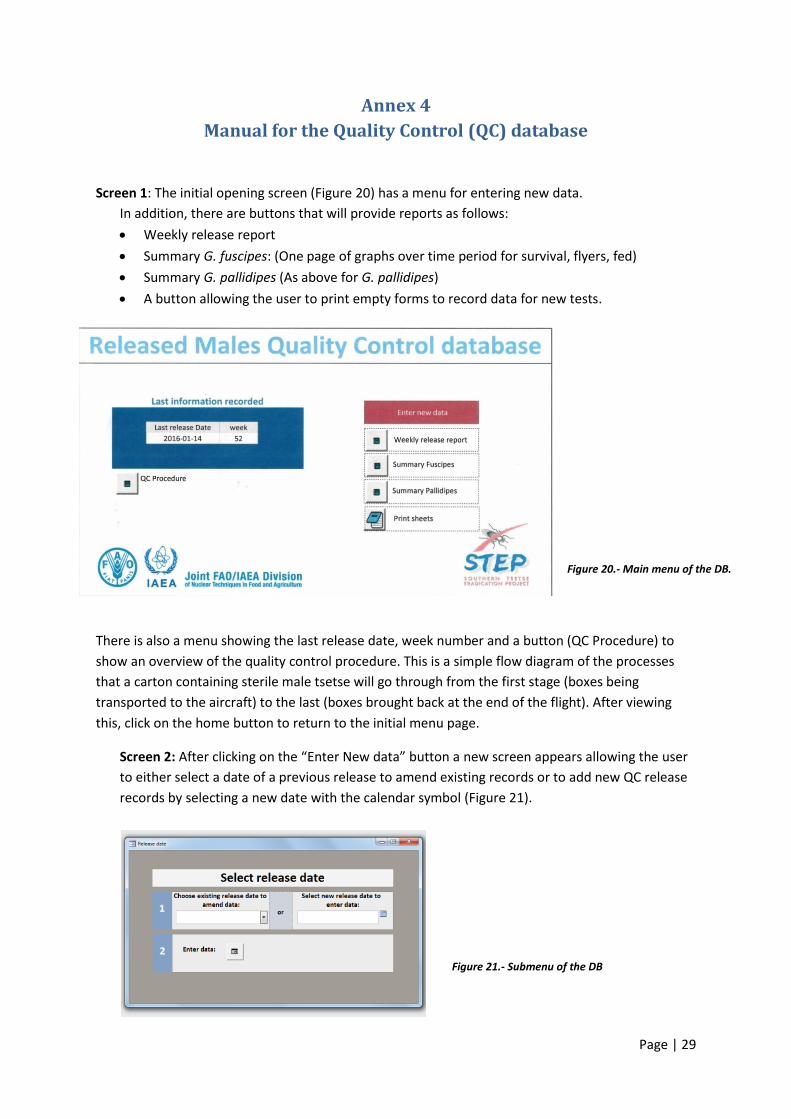
Screen 1: The initial opening screen (Figure 20) has a menu for entering new data.
In addition, there are buttons that will provide reports as follows:
Weekly release report
Summary G. fuscipes: (One page of graphs over time period for survival, flyers, fed)
Summary G. pallidipes (As above for G. pallidipes)
A button allowing the user to print empty forms to record data for new tests.
There is also a menu showing the last release date, week number and a button (QC Procedure) to
show an overview of the quality control procedure. This is a simple flow diagram of the processes
that a carton containing sterile male tsetse will go through from the first stage (boxes being
transported to the aircraft) to the last (boxes brought back at the end of the flight). After viewing
this, click on the home button to return to the initial menu page.
Screen 2: After clicking on the “Enter New data” button a new screen appears allowing the user
to either select a date of a previous release to amend existing records or to add new QC release
records by selecting a new date with the calendar symbol (Figure 21).
Figure 20.- Main menu of the DB.
Figure 21.- Submenu of the DB
Page | 30
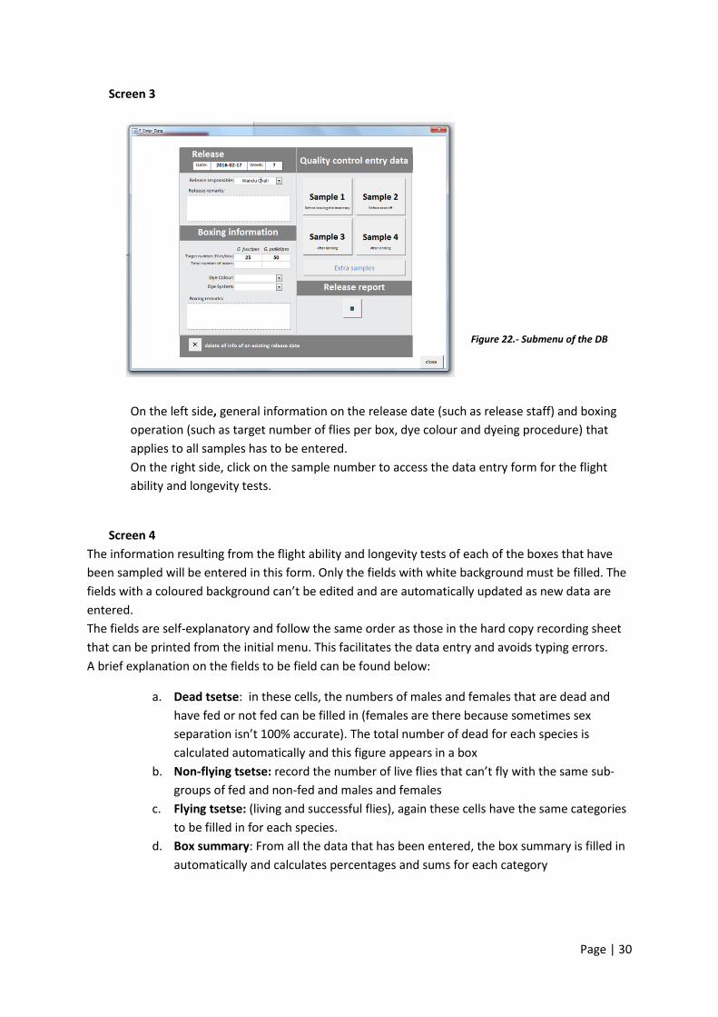
Screen 3
On the left side, general information on the release date (such as release staff) and boxing
operation (such as target number of flies per box, dye colour and dyeing procedure) that
applies to all samples has to be entered.
On the right side, click on the sample number to access the data entry form for the flight
ability and longevity tests.
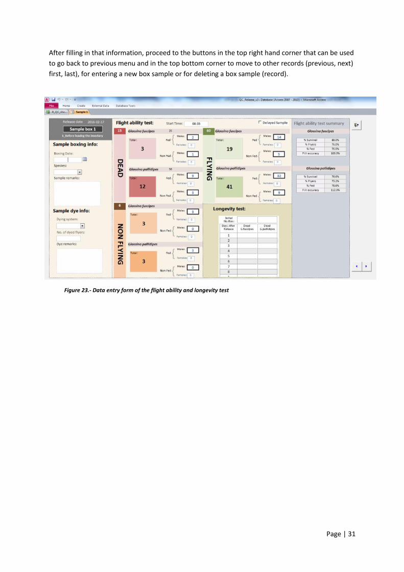
Screen 4
The information resulting from the flight ability and longevity tests of each of the boxes that have
been sampled will be entered in this form. Only the fields with white background must be filled. The
fields with a coloured background can’t be edited and are automatically updated as new data are
entered.
The fields are self-explanatory and follow the same order as those in the hard copy recording sheet
that can be printed from the initial menu. This facilitates the data entry and avoids typing errors.
A brief explanation on the fields to be field can be found below:
a. Dead tsetse: in these cells, the numbers of males and females that are dead and
have fed or not fed can be filled in (females are there because sometimes sex
separation isn’t 100% accurate). The total number of dead for each species is
calculated automatically and this figure appears in a box
b. Non-flying tsetse: record the number of live flies that can’t fly with the same sub-
groups of fed and non-fed and males and females
c. Flying tsetse: (living and successful flies), again these cells have the same categories
to be filled in for each species.
d. Box summary: From all the data that has been entered, the box summary is filled in
automatically and calculates percentages and sums for each category
Figure 22.- Submenu of the DB
Page | 31
After filling in that information, proceed to the buttons in the top right hand corner that can be used
to go back to previous menu and in the top bottom corner to move to other records (previous, next)
first, last), for entering a new box sample or for deleting a box sample (record).
Figure 23.- Data entry form of the flight ability and longevity test
Page | 32
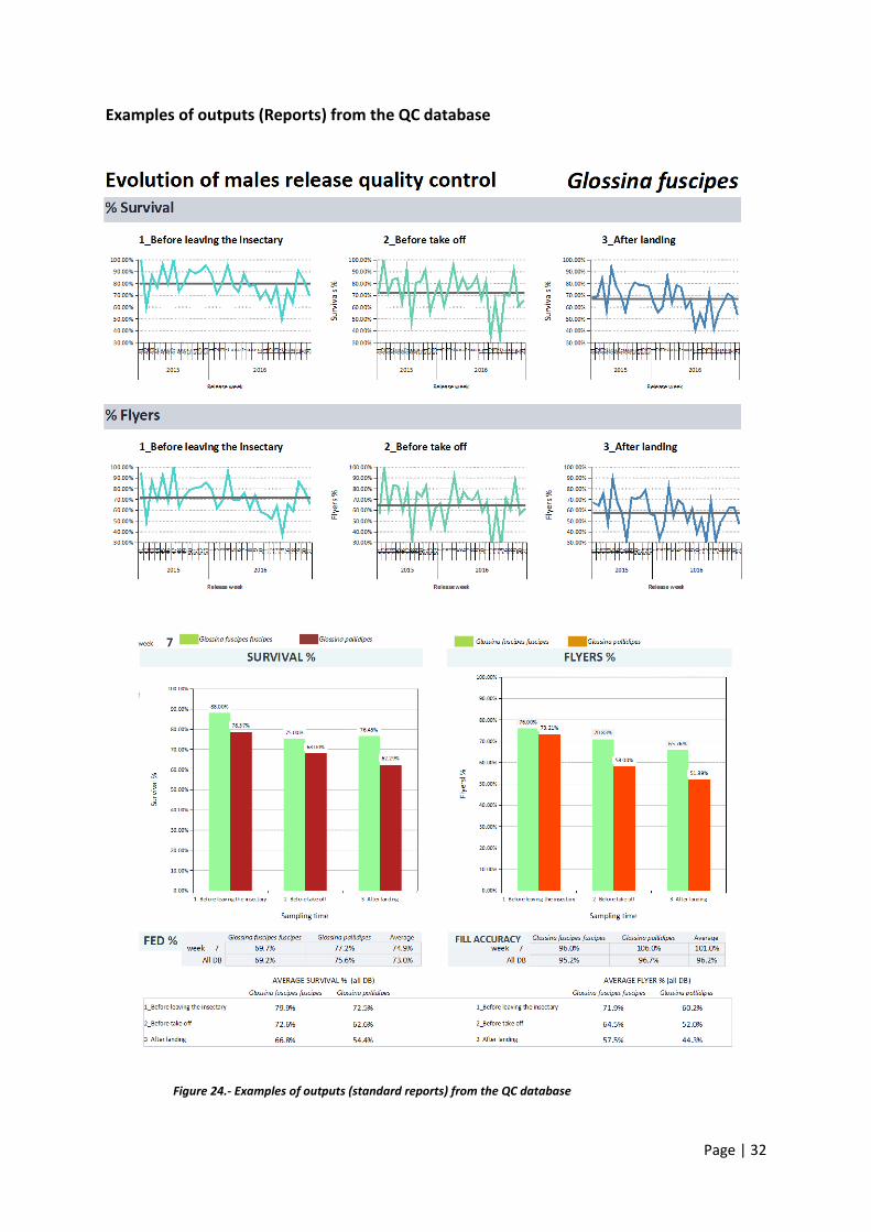
Examples of outputs (Reports) from the QC database
Figure 24.- Examples of outputs (standard reports) from the QC database
Page | 33
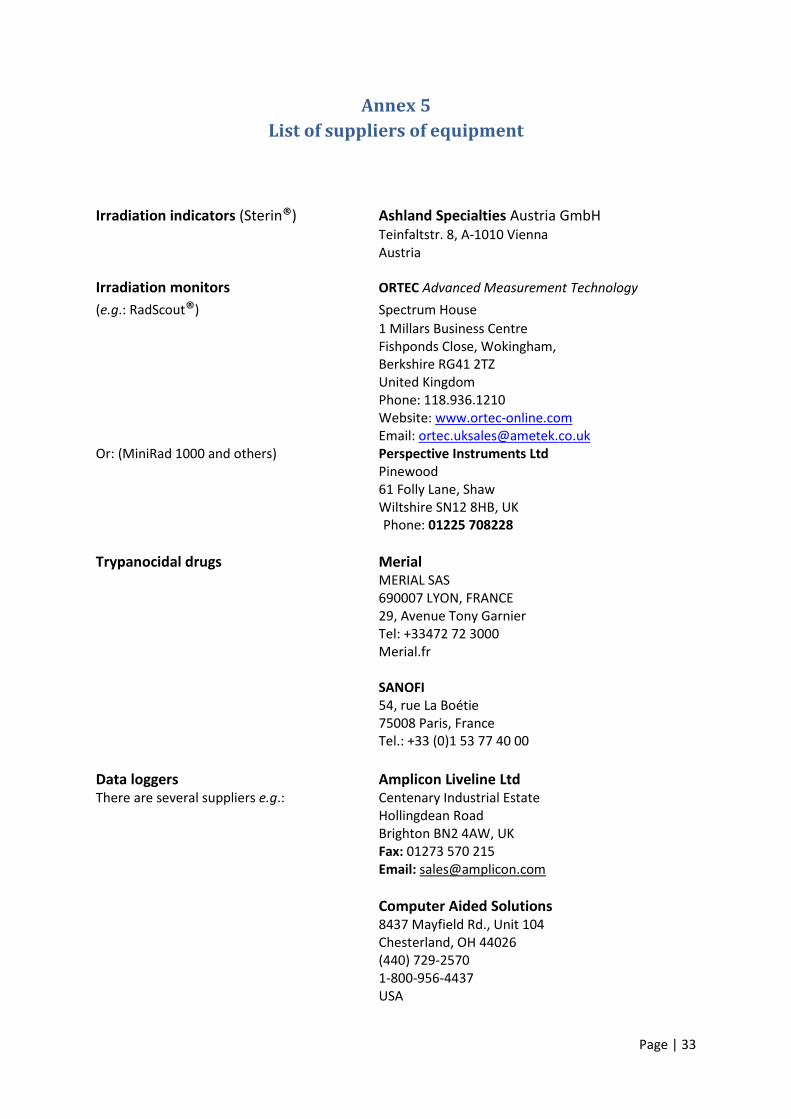
Annex 5
List of suppliers of equipment
Irradiation indicators (Sterin®) Ashland Specialties Austria GmbH Teinfaltstr. 8, A-1010 Vienna Austria
Irradiation monitors ORTEC Advanced Measurement Technology
(e.g.: RadScout®) Spectrum House
1 Millars Business Centre Fishponds Close, Wokingham, Berkshire RG41 2TZ United Kingdom Phone: 118.936.1210 Website: www.ortec-online.com Email: [email protected] Or: (MiniRad 1000 and others) Perspective Instruments Ltd Pinewood 61 Folly Lane, Shaw Wiltshire SN12 8HB, UK Phone: 01225 708228
Trypanocidal drugs Merial MERIAL SAS 690007 LYON, FRANCE 29, Avenue Tony Garnier Tel: +33472 72 3000 Merial.fr SANOFI
54, rue La Boétie 75008 Paris, France
Tel.: +33 (0)1 53 77 40 00
Data loggers Amplicon Liveline Ltd There are several suppliers e.g.: Centenary Industrial Estate Hollingdean Road Brighton BN2 4AW, UK Fax: 01273 570 215 Email: [email protected]
Computer Aided Solutions 8437 Mayfield Rd., Unit 104 Chesterland, OH 44026 (440) 729-2570 1-800-956-4437 USA
Page | 34
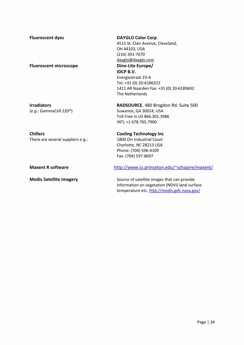
Fluorescent dyes DAYGLO Color Corp. 4515 St. Clair Avenue, Cleveland, OH 44103, USA (216) 391-7070 [email protected]
Fluorescent microscope Dino-Lite Europe/ IDCP B.V. Energiestraat 23-A Tel: +31 (0) 20-6186322 1411 AR Naarden Fax: +31 (0) 20-6189692 The Netherlands
Irradiators RADSOURCE, 480 Brogdon Rd. Suite 500 (e.g.: GammaCell 220®) Suwanee, GA 30024, USA Toll Free in US 866.301.3986 INTL +1 678.765.7900
Chillers Cooling Technology Inc There are several suppliers e.g.: 1800 Orr Industrial Court Charlotte, NC 28213 USA Phone: (704) 596-4109 Fax: (704) 597-8697
Maxent R software http://www.cs.princeton.edu/~schapire/maxent/ Modis Satellite imagery Source of satellite images that can provide information on vegetation (NDVI) land surface temperature etc. http://modis.gsfc.nasa.gov/
Page | 35
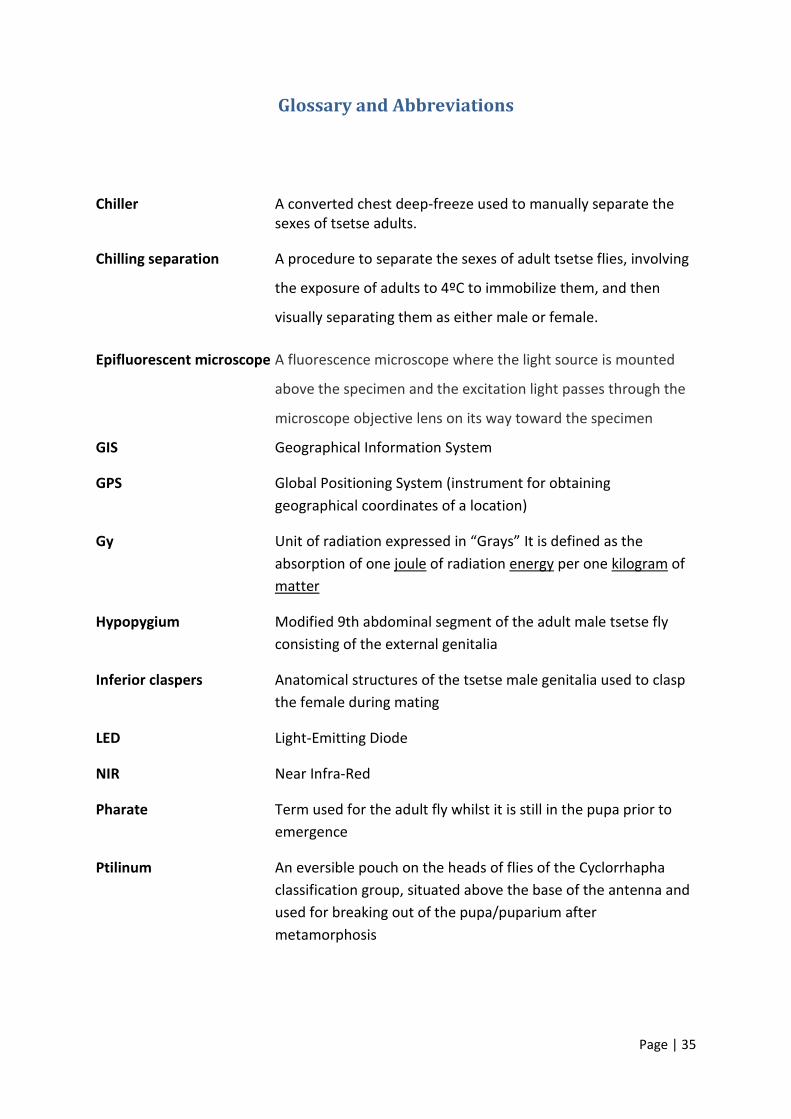
Glossary and Abbreviations
Chiller A converted chest deep-freeze used to manually separate the sexes of tsetse adults.
Chilling separation A procedure to separate the sexes of adult tsetse flies, involving
the exposure of adults to 4ºC to immobilize them, and then
visually separating them as either male or female.
Epifluorescent microscope A fluorescence microscope where the light source is mounted
above the specimen and the excitation light passes through the
microscope objective lens on its way toward the specimen
GIS Geographical Information System
GPS Global Positioning System (instrument for obtaining
geographical coordinates of a location)
Gy Unit of radiation expressed in “Grays” It is defined as the
absorption of one joule of radiation energy per one kilogram of
matter
Hypopygium Modified 9th abdominal segment of the adult male tsetse fly
consisting of the external genitalia
Inferior claspers Anatomical structures of the tsetse male genitalia used to clasp
the female during mating
LED Light-Emitting Diode
NIR Near Infra-Red
Pharate Term used for the adult fly whilst it is still in the pupa prior to
emergence
Ptilinum An eversible pouch on the heads of flies of the Cyclorrhapha
classification group, situated above the base of the antenna and
used for breaking out of the pupa/puparium after
metamorphosis
Page | 36
Puparium The hardened outer case around the outside of the pupa of the
fly during metamorphosis (development from the larva to the
adult fly)
QC Quality Control
RPO Radiation Protection Officer
Self-stocking production cage (SSPC): In this procedure, newly emerged adults penetrate by themselves the netting of a “standard holding cage”, and thus enter directly into a “production cage”.
SOP Standard Operating Procedures
Spiracles Openings in the thorax connected to trachea (tubes for air to
enter the body of the fly) for respiration
SSPC Self-Stocking Pupal Cages
Standard holding cage A cage made from 200-mm-diameter polyvinyl chloride (PVC)
drain pipe, 50 mm tall, with netting on both sides, and a 21-mm
hole on the side plugged with a rubber stopper (permitting flies
to be inserted or taken out).
Superior claspers Anatomical structures of the tsetse male genitalia used to clasp
the female during mating - larger and to the exterior of the
inferior claspers
Teneral (tsetse fly) A newly emerged fly that has yet to take its first blood meal
TLD Thermo-Luminescent Dosimeter (for measuring exposure to
radiation)
TPU Tsetse Production Unit
Truncated Shortened/abbreviated
UV Ultraviolet radiation
Page | 37
List of Figures and Tables
Figure 1.- Flow chart of procedures and techniques used in preparation and release of sterile male
tsetse ....................................................................................................................................................... 4
Figure 2.- Example of a commercial formulation of Isometamidium .................................................... 6
Figure 3. Tsetse flies dyed with different colours .................................................................................... 7
Figure 4.- Flies with excess dye ............................................................................................................... 8
Figure 5. Emerging fly. Red arrow shows the inflated ptilinum after breaking the puparium. ............. 8
Figure 6.- Dinolite UV camera coupled with a laptop ............................................................................. 9
Figure 7.- Female (A) and male (B) sexual characters .......................................................................... 10
Figure 8. Chillers showing an emergence cage and adults immobilized by the cold during sex
separation ............................................................................................................................................. 10
Figure 9.- Example of an emergence dynamics chart ........................................................................... 11
Figure 10.- Female and male puparia of Glossina palpalis gambiensis at day 26 viewed under NIR
light. Females (top row) show obvious pigmentation in the wings and legs, whereas males do not .. 12
Figure 11.- Irradiation indicator ............................................................................................................ 13
Figure 12.- Irradiation of males using a Gammacell 220 irradiator. .................................................... 14
Figure 13.- Packing operation showing the Thermos flask adapted with a funnel ............................... 15
Figure 14.- Example of a data logger that can be connected to the USB port of a PC. ........................ 17
Figure 15.- Electronic release counter. A: display of main unit. B: GPS antenna. C: Optic sensor to be
fixed at the end of the bottom chute .................................................................................................... 18
Figure 16.- Map with the release sections covering the predicted distribution area in the Deme
eradication project ................................................................................................................................ 19
Figure 17.- Release map. ....................................................................................................................... 20
Figure 18.- Quality control testing and monitoring of the mortality of starved flies (Photos: M.T. Seck)
.............................................................................................................................................................. 22
Figure 19.- Form to record the results of the flight ability and longevity tests. .................................... 22
Figure 20.- Main menu of the DB. ......................................................................................................... 29
Figure 21.- Submenu of the DB ............................................................................................................. 29
Figure 22.- Submenu of the DB ............................................................................................................. 30
Figure 23.- Data entry form of the flight ability and longevity test ...................................................... 31
Figure 24.- Examples of outputs (standard reports) from the QC database ......................................... 32
Table 1.- Ranges of optimal environmental conditions for tsetse flies ................................................. 23
Table 2.- Number of pupae required to load one adult cage at the optimal density ........................... 24
Recommended