Joint Standard Document between Energex and Ergon Energy
Energex Limited ABN 40 078 849 055 Ergon Energy Corporation Limited ABN 50 087 646 062
Substation Standard
Standard for Selection of Surge Arresters
These standards created and made available are for the construction of Energy Queensland
infrastructure. These standards ensure meeting of Energy Queensland’s requirements. External
companies should not use these standards to construct non-Energy Queensland assets.
If this standard is a printed version, to ensure compliance, reference must be made to the Energy
Queensland internet site to obtain the latest version.
Approver Carmelo Noel
General Manager Asset Standards
If RPEQ sign off required insert details below.
Energy Queensland
Certified Person name and Position Registration Number
John Lansley
Manager Substation Standards
RPEQ 6371
Abstract: The aim of this document is to establish procedures for selecting gapless metal-oxide
surge arresters connected between phase and earth for alternating current systems with the
objective of providing protection for electrical plant against voltage surges due to lightning and
circuit switching.
Keywords: Surge arrester, protection, standard, substation
Standard for Selection of Surge Arresters
Check this is the latest version before use ii EX 02116 Ver 1
EE STNW3033 Ver 1
Joint Standard Document between Energex and Ergon Energy
Energex Limited ABN 40 078 849 055 Ergon Energy Corporation Limited ABN 50 087 646 062
For definitive document version and control detail, please refer to the information stored on the
Process Zone.
Revision history
Revision date Version
number
Author Description of change/revision
29/06/2003 0.1.0 Qui Dinh Approved for issue
13/06/2007 0.1.1 Qui Dinh Header changed. Footer modified
Clause 10 – References modified &
moved to become clause 2
Clause 2 – Background moved to
become clause 4.
Clause 1 modified
Heading of Clause 5 (now 6) modified
Clause 5.4.3 (now 6.4.3) voltage 132 kV
corrected to 123 kV
Clause 5.5.2.1 Notations of Equation 1
changed.
Clause 5.5.2.2 formula for ke added
Clause 5.7.1 last para, reference added
Appendices A & B swapped
29/04/2008 0.2.0 Qui Dinh Clause 2. Reference 11 added
Clause 6.5.2.1 Equation 3 added
Clause 6.5.4.2 modified
Clause 6.6 Determination of nominal
discharge current, modified.
Clauses 6.9 & 6.12 added
Clause 6.10.1 Equation 8 added
Clause 9.2. Modified by adding sub-
headings 9.2.1 & 9.2.2. New clause
9.2.1.
Appendix G added
01/06/08 0.2.1 Qui Dinh Comments from SSG incorporated
26/02/2014 0.2.2 Cassie Caldwell Copy to new template
05/02/2021 1 Kate Watson Copy to new dual branded template
Section 2.3 References to IEEE
standards removed
Section 7.3 Equations for continuous
voltage changed to reflect the safety
factors already in the EQL network
Section 7.6.3 Factor of 2 added to the
arrester energy equation for arresters
with known volt-ampere characteristics
Standard for Selection of Surge Arresters
Check this is the latest version before use iii EX 02116 Ver 1
EE STNW3033 Ver 1
Joint Standard Document between Energex and Ergon Energy
Energex Limited ABN 40 078 849 055 Ergon Energy Corporation Limited ABN 50 087 646 062
Section 7.7.1 Arrester classes changed
to reflect the latest changes to IEC
60099-4
Sections 8 and 9 regarding insulation
coordination removed. Refer to
STNW3034.
Annex D Added including updated Surge
Arrester Selection Guide (EQL SS-1-8.3
Selection of Surge Arresters)
Document approvals
Name Position title Signature Date
Carmelo Noel General Manager Asset Standards
Stakeholders / distribution list
Name Title Role
John Lansley Manager Substation Standards Endorse
Standard for Selection of Surge Arresters
Check this is the latest version before use iv EX 02116 Ver 1
EE STNW3033 Ver 1
Joint Standard Document between Energex and Ergon Energy
Energex Limited ABN 40 078 849 055 Ergon Energy Corporation Limited ABN 50 087 646 062
Table of Contents
1 Overview .............................................................................................................................. 1
1.1 Purpose ...................................................................................................................... 1
2 References ........................................................................................................................... 1
2.1 Ergon Energy controlled documents ........................................................................... 1
2.2 Energex controlled documents .................................................................................... 1
2.3 Other documents ........................................................................................................ 1
3 Legislation, regulations, rules, and codes ............................................................................. 2
4 Definitions, acronyms, and abbreviations.............................................................................. 2
4.1 Definitions ................................................................................................................... 2
4.2 Acronyms and abbreviations ....................................................................................... 5
5 Background .......................................................................................................................... 5
6 General procedure for selection of gapless surge arresters .................................................. 6
7 Selection of surge arrester ratings ........................................................................................ 7
7.1 Step 1: Obtain system parameters .............................................................................. 7
7.2 Step 2: Check for abnormal service conditions............................................................ 7
7.3 Step 3: Determine Continuous Voltage (Uc) ................................................................ 7
7.3.1 Recommended Continuous Voltage ................................................................ 7
7.4 Step 4: Determine Temporary Overvoltage capability and Rated Voltage (Ur)............. 8
7.4.1 Check for maximum TOV ................................................................................ 8
7.4.2 Earth fault conditions ...................................................................................... 8
7.4.3 Other cases .................................................................................................... 8
7.4.4 Select suitable TOV capability and Rated Voltage (Ur) ................................... 8
7.5 Step 5: Determine nominal discharge current, In ....................................................... 10
7.6 Step 6: Determine energy withstand capability and specific energy .......................... 10
7.6.1 General ......................................................................................................... 10
7.6.2 Line switching parameters ............................................................................ 11
7.6.3 Calculate the arrester energy ........................................................................ 11
7.6.4 Determine specific energy ............................................................................. 12
7.7 Step 7: Arrester class ................................................................................................ 12
7.7.1 Determine arrester class ............................................................................... 12
7.7.2 Recommended minimum class ..................................................................... 12
7.8 Step 8: Determination of protective characteristics .................................................... 12
7.9 Step 9: Pressure relief (applicable to porcelain housed SA only) .............................. 12
Standard for Selection of Surge Arresters
Check this is the latest version before use v EX 02116 Ver 1
EE STNW3033 Ver 1
Joint Standard Document between Energex and Ergon Energy
Energex Limited ABN 40 078 849 055 Ergon Energy Corporation Limited ABN 50 087 646 062
7.9.1 Pressure relief current ................................................................................... 12
7.9.2 Pressure relief class ...................................................................................... 12
7.10 Step 10: External insulation levels............................................................................. 12
7.11 Step 11: Mechanical characteristics .......................................................................... 13
7.12 Step 12: Pollution performance ................................................................................. 13
8 Determination of protective levels of an arrester ................................................................. 13
8.1 Evaluating insulation co-ordination ............................................................................ 14
8.2 Arresters at terminals of protected equipment ........................................................... 14
8.3 Arresters at some distance away from protected equipment ..................................... 15
9 Evaluation of alternatives .................................................................................................... 15
10 Documentation required ..................................................................................................... 15
Annex A Coefficient of earthing (COE) and earth fault factor (ke) ............................................ 16
A.1. Coefficient of earthing ............................................................................................... 16
A.2. Earth fault factor (ke)................................................................................................. 16
Annex B Annex C of IEEE Std C62.22-1997 ........................................................................... 17
Annex C Pollution severity levels and minimum creepage distance ......................................... 26
Annex D How to use EQL Selection of Surge Arresters Workbook: ......................................... 28
D.1. Title ........................................................................................................................... 28
D.2. Useful Information ..................................................................................................... 28
D.3. Useful Formulae ........................................................................................................ 28
D.4. Input Data ................................................................................................................. 28
D.5. Summary of SA Performance .................................................................................... 29
D.6. Supplier Data ............................................................................................................ 29
D.7. Lookup Tables .......................................................................................................... 30
D.8. Example analysis ...................................................................................................... 30
Standard for Selection of Surge Arresters
Check this is the latest version before use Page 1 EX 02116 Ver 1
EE STNW3033 Ver 1
Joint Standard Document between Energex and Ergon Energy
Energex Limited ABN 40 078 849 055 Ergon Energy Corporation Limited ABN 50 087 646 062
1 Overview
1.1 Purpose
This document defines methods, parameters and procedure in selecting gapless metal-oxide surge
arrester connected between phase and earth for alternating current systems for the protection of
electrical plant against voltage surges due to lightning and circuit switching.
This document does not cover specific aspects of the application of surge arresters and the
required mechanical strength.
2 References
2.1 Ergon Energy controlled documents
Document number or location
(if applicable)
Document name Document type
2.2 Energex controlled documents
Document number or location
(if applicable)
Document name Document type
2.3 Other documents
Document number or location
(if applicable)
Document name Document type
AS 1307.2 Metal-oxide surge arresters without
gaps for A.C. systems
Australian Standard
AS 4436
Guide for the selection of insulators in
respect of polluted conditions
Australian Standard
IEC 60099-1 Surge Arresters – Part 1: Non-linear
Resistor Type Gapped Surge Arresters
for A.C. Systems
International Standard
IEC 60099-3 Surge Arresters – Part 3: Artificial
Pollution Testing of Surge Arresters
International Standard
IEC 60099-4 Surge Arresters - Part 4: Metal-oxide
Surge Arresters Without Gaps for A.C.
Systems
International Standard
IEC 60099-5 Surge Arresters - Part 5: Selection and
Application Recommendations
International Standard
IEC 60099-7 Surge Arresters - Part 7: Glossary of
Terms and Definitions from IEC
publications 60099-1, 4, 5
International Standard
IEEE Std C62.22-2009 IEEE Guide for Application of Metal-
Oxide Surge Arresters for Alternating-
International Standard
Standard for Selection of Surge Arresters
Check this is the latest version before use Page 2 EX 02116 Ver 1
EE STNW3033 Ver 1
Joint Standard Document between Energex and Ergon Energy
Energex Limited ABN 40 078 849 055 Ergon Energy Corporation Limited ABN 50 087 646 062
Document number or location
(if applicable)
Document name Document type
Current Systems
ABB Buyer’s Guide, Edition 5,
2003 - 2010
High Voltage Surge Arresters Buyer’s
Guide
Industrial Technical Publication
SESWG/A-2310 E Edition 2,
1995-2010
Application guidelines for station
protection, ABB
Industrial Technical Publication
3 Legislation, regulations, rules, and codes
This document complies with the legislation in the following documents:
Legislation, regulations, rules, and codes
(Queensland Electrical Safety Act, 2002) (Queensland Government)
(Queensland Electrical Safety Regulation, 2013) (Queensland Government)
(Queensland Electricity Act, 1994) (Queensland Government)
(Queensland Electricity Regulation, 2006) (Queensland Government)
(Queensland Work Health and Safety Act, 2011) (Queensland Government)
(Queensland Work Health and Safety Regulation, 2011) (Queensland Government)
(National Electricity Rules, 2018) (AEMC)
4 Definitions, acronyms, and abbreviations
4.1 Definitions
For the purposes of this standard, the following definitions apply:
Term Definition
Actual continuous
operating voltage
(Uca)
The maximum r.m.s power frequency voltage which is applied continuously (≥ 2
hours) between the arrester terminals.
Arrester or Surge
Arrester (SA)
A protective device for limiting surge voltages on equipment by diverting surge
current and returning the device to its original status. It is capable of repeating
these functions as specified.
Arrester protective
characteristic
A combination of its residual voltages for different current impulses. For good
protection the arrester characteristic should lie well below the protected equipment
insulation withstand characteristic at all points.
Coefficient of earthing
(COE) or Coefficient
of grounding (COG)
The ratio ULE/ULL (express as percentage) of the highest r.m.s line-to-ground power
frequency voltage ULE on a sound phase, at a selected location, during a fault to
ground affecting one or more phases to the line-to-line power frequency voltage ULL
that would be obtained at the selected location with the fault removed. COE is equal
to Earth fault factor multiplied by 100/√3.
Continuous current The current flowing through the arrester when energised at continuous operating
Standard for Selection of Surge Arresters
Check this is the latest version before use Page 3 EX 02116 Ver 1
EE STNW3033 Ver 1
Joint Standard Document between Energex and Ergon Energy
Energex Limited ABN 40 078 849 055 Ergon Energy Corporation Limited ABN 50 087 646 062
(Ic) voltage.
Continuous operating
voltage (Uc)
(Often abbreviated as COV or MCOV) is the designated permissible r.m.s value of
power frequency voltage may be applied continuously between the arrester
terminals. Thus Uc > Uca.
Critical flashover
voltage (CFO)
The amplitude of voltage of a given waveshape that, under specified conditions,
causes flashover through the surrounding medium on 50% of the voltage
applications (IEEE C62.22, 2009).
Discharge current The impulse current which flows through the arrester.
Discharge voltage Refer to Residual voltage.
Disruptive discharge The sudden and large increase in current through an insulating medium due to the
complete failure of the medium under electrical stress (IEEE C62.22, 2009).
Duty cycle voltage Refer to Rated voltage.
Earth fault factor (ke) At a selected location of a three-phase system is the ratio of the highest r.m.s
phase-to-earth power frequency voltage on a sound phase during a fault to earth
(affecting one or more phases at any point) to the r.m.s phase-to-earth power
frequency voltage which would be obtained at the selected location with the fault
removed. If ke ≤ 1.4 the system at that location is referred as effectively earthed,
otherwise non-effectively earthed. In a system with a resonant earthed neutral or
isolated neutral ke = 1.73.
Equipment insulation
withstand
characteristic
Is a general term for the equipment insulation withstand voltage and comprises:
Withstand level Voltage waveshape
Chopped (steep) wave withstand level (CWW)
Lightning impulse withstand level (LIWL or BIL) 1.2/50
Switching impulse withstand level (SIWL) 250/2500
Power frequency withstand level (PFWL) 50 or 60 Hz sinusoidal
Impulse A surge of unidirectional polarity.
Impulse (of current or
voltage)
Impulse is a unidirectional wave, which rises rapidly to a maximum and falls, a little
less rapidly, to zero. Its waveshape is expressed by two numbers (T1/T2). T1
refers to the virtual front time and T2 to the virtual time to half value of the tail; both
expressed in microseconds.
Some important current impulses are:
Impulse Waveshape (T1/T2)
Steep current impulse T1 = 1 µs T2 ≤ 20 µs
Lightning current impulse T1 = 8 µs T2 = 20 µs
Switching current impulse T1 ≥ 30 µs T2 ≥ 60 µs
High current impulse T1 = 4 µs T2 = 10 µs
A special impulse is the rectangular current impulse, which is the shape of a
rectangle. A common duration is 2000 µs.
Insulation co-
ordination
The selection of the dielectric strength of equipment in relation to the voltages,
which can appear on the system for which the equipment is intended and taking into
account the service environment and the characteristics of the available protective
Standard for Selection of Surge Arresters
Check this is the latest version before use Page 4 EX 02116 Ver 1
EE STNW3033 Ver 1
Joint Standard Document between Energex and Ergon Energy
Energex Limited ABN 40 078 849 055 Ergon Energy Corporation Limited ABN 50 087 646 062
devices.
Lightning current
impulse
A 8/20 µs current impulse.
Lightning impulse
protection level (LPL)
The LPL of an arrester is the residual voltage for the nominal discharge current.
Lightning impulse
withstand voltage
(LIWV) or Basic
insulation level (BIL)
The electrical strength of insulation expressed in crest value of a standard lightning
impulse under standard atmospheric conditions (IEEE C62.22, 2009).
Nominal discharge
current (In)
The peak value of lightning current impulse which is used to classify an arrester.
Pressure relief
capability
The ability of an arrester, in the event of its overloading due to any reason, to
conduct the resulting system short circuit current through it without a violent
explosion (IEEE C62.22, 2009). After the operation of the pressure relief, the
arrester must be removed
Prior duty In order to test if an arrester is capable of functioning during and after successive
faults, prior duty testing is conducted where the thermal energy W th is injected into
the arrester over a nominated duration (typically 3 minutes) before residual voltage
tests are conducted (IEC 60099-4, 2014). Residual voltages after application of
prior duty are typically 5-10% lower than those without prior duty.
Protective margin The protective ratio minus one and expressed as percentage.
Protective ratio The ratio of the equipment insulation withstand level to the corresponding protection
level of its arrester.
Rated voltage (Ur) The maximum permissible r.m.s value of power frequency voltage between its
terminals at which it is designed to operate correctly under temporary overvoltage
conditions as established in the operating duty tests.
Note: As per AS 1307.2 the arrester must withstand its rated voltage for at least 10
s after being both preheated to 60°C and subjected to a high energy injection as
defined in the standard. Hence, the TOV capability for 10 s has to be minimum Ur.
Continuous application of this voltage will damage the arrester.
Residual voltage
(Ures)
The peak value of voltage that appears between the terminals of an arrester during
the passage of discharge current.
Surge impedance (Z) The surge impedance of a conductor is a mathematical constant, approximately
equal to the square root of the quotient of the inductance of the conductor and the
capacitance between the conductor and ground (AS/NZS 4436, 1996).
Switching impulse
withstand voltage
(SIWV) or Basic
switching insulation
level (BSL)
The electrical strength of insulation expressed in crest value of a standard switching
impulse (IEEE C62.22, 2009).
Temporary
overvoltages (TOV)
Temporary overvoltages as differentiated from surge overvoltages, are oscillatory
overvoltages of relatively long duration and which are undamped or only weakly
damped.
Temporary The TOV capability of the arrester expressed in multiple of Ur or Uc.
Standard for Selection of Surge Arresters
Check this is the latest version before use Page 5 EX 02116 Ver 1
EE STNW3033 Ver 1
Joint Standard Document between Energex and Ergon Energy
Energex Limited ABN 40 078 849 055 Ergon Energy Corporation Limited ABN 50 087 646 062
overvoltage withstand
factor (Tr or Tc)
Virtual front time of a
current impulse (T1)
The time in microseconds equal to 1.25 multiplied by the time in microseconds for
the current to increase from 10% to 90% of its peak value.
4.2 Acronyms and abbreviations
The following abbreviations and acronyms appear in this standard.
Term, abbreviation or
acronym
Definition
CFO Critical flashover voltage
COE/ COG Coefficient of earthing/ coefficient of grounding
EQL Energy Queensland Limited
Ic Continuous current
In Nominal discharge current
ke Earth fault factor
LIWV/ BIL Lightning impulse withstand voltage/ basic insulation level
LPL Lightning impulse protection level
Ures Residual voltage
SA Surge arrester
SIWV/ BSL Switching impulse withstand voltage/ Switching insulation level
TOV Temporary overvoltage
Tr Temporary overvoltage withstand factor
Uc Continuous operating voltage
Uca Actual continuous operating voltage
Ur Rated voltage
Z Surge impedance
5 Background
Two broad categories of surge arresters have been used in the network:
1. Metal-oxide surge arresters (MOSA) consisting of highly non-linear stable zinc oxide (ZnO)
value blocks.
2. Gap type arresters consisting of a series connection of a spark gap and a non-linear
resistor made of silicon carbide (no longer purchased but exist on the network).
Metal oxide arresters fall into three broad design types, namely: gapless arresters, shunt-gapped
arresters and series-gapped arresters. Gap-less arresters are purchased by Energy Queensland.
Standard for Selection of Surge Arresters
Check this is the latest version before use Page 6 EX 02116 Ver 1
EE STNW3033 Ver 1
Joint Standard Document between Energex and Ergon Energy
Energex Limited ABN 40 078 849 055 Ergon Energy Corporation Limited ABN 50 087 646 062
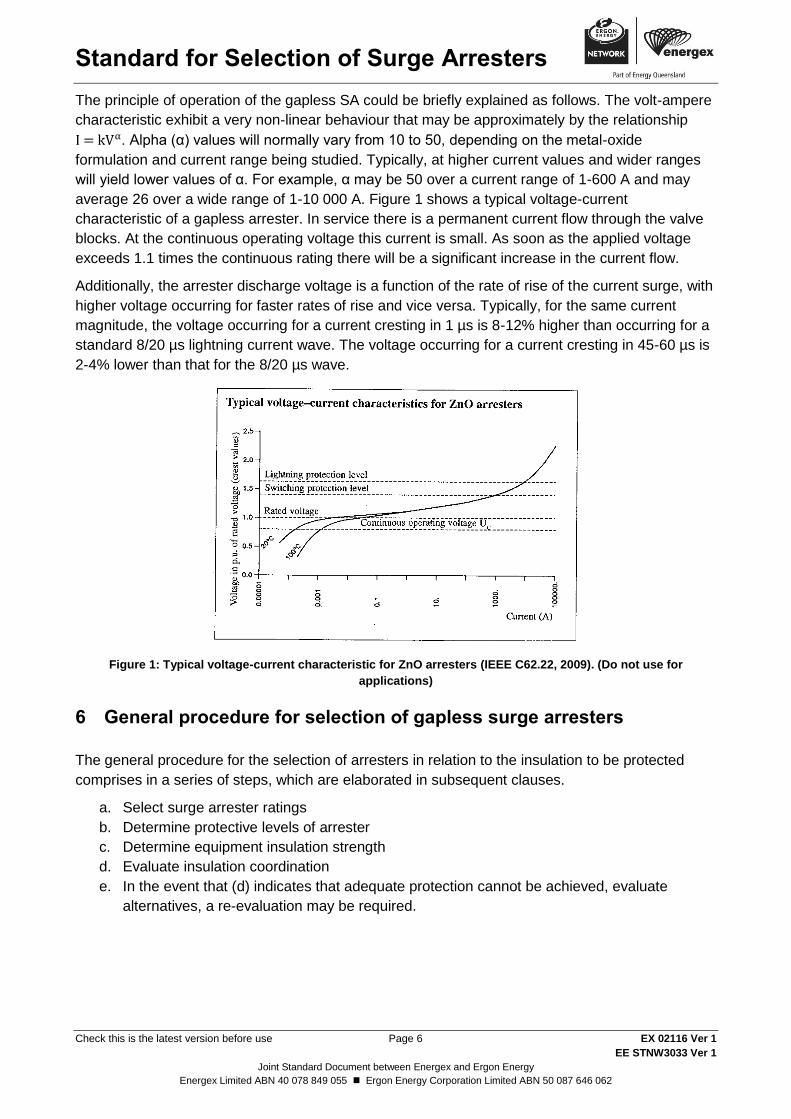
The principle of operation of the gapless SA could be briefly explained as follows. The volt-ampere
characteristic exhibit a very non-linear behaviour that may be approximately by the relationship
. Alpha (α) values will normally vary from 10 to 50, depending on the metal-oxide
formulation and current range being studied. Typically, at higher current values and wider ranges
will yield lower values of α. For example, α may be 50 over a current range of 1-600 A and may
average 26 over a wide range of 1-10 000 A. Figure 1 shows a typical voltage-current
characteristic of a gapless arrester. In service there is a permanent current flow through the valve
blocks. At the continuous operating voltage this current is small. As soon as the applied voltage
exceeds 1.1 times the continuous rating there will be a significant increase in the current flow.
Additionally, the arrester discharge voltage is a function of the rate of rise of the current surge, with
higher voltage occurring for faster rates of rise and vice versa. Typically, for the same current
magnitude, the voltage occurring for a current cresting in 1 µs is 8-12% higher than occurring for a
standard 8/20 µs lightning current wave. The voltage occurring for a current cresting in 45-60 µs is
2-4% lower than that for the 8/20 µs wave.
Figure 1: Typical voltage-current characteristic for ZnO arresters (IEEE C62.22, 2009). (Do not use for
applications)
6 General procedure for selection of gapless surge arresters
The general procedure for the selection of arresters in relation to the insulation to be protected
comprises in a series of steps, which are elaborated in subsequent clauses.
a. Select surge arrester ratings
b. Determine protective levels of arrester
c. Determine equipment insulation strength
d. Evaluate insulation coordination
e. In the event that (d) indicates that adequate protection cannot be achieved, evaluate
alternatives, a re-evaluation may be required.
Standard for Selection of Surge Arresters
Check this is the latest version before use Page 7 EX 02116 Ver 1
EE STNW3033 Ver 1
Joint Standard Document between Energex and Ergon Energy
Energex Limited ABN 40 078 849 055 Ergon Energy Corporation Limited ABN 50 087 646 062
7 Selection of surge arrester ratings
Characteristics and performance of a SA are determined by the following parameters:
a. Continuous voltage (Uc)
b. Rated voltage (Ur)
c. Nominal discharge current (In)
d. Specific energy
e. Line discharge class
f. Pressure relief class (porcelain housing only)
g. External insulation level
h. Pollution performance
7.1 Step 1: Obtain system parameters
The following data are required to determine arrester parameters:
a. System nominal voltage, Un and maximum voltage, Um
b. Earthing of system neutral
c. Positive and zero sequence impedances at the SA location
d. Possible causes of overvoltages
e. Length of the longest line to which SA will be connected
f. Line surge impedance, Z, and/or line capacitance, C
g. Prospective fault levels at arrester location
7.2 Step 2: Check for abnormal service conditions
Abnormal service conditions are listed in Appendix A of AS 1307.2. Some of the most important
conditions that may lead to selection of higher Uc and/or Ur are:
a. Temperatures below -10°C or above +50°C
b. Frequencies under 48 Hz or above 52 Hz (for 50 Hz systems)
c. Presence of heat sources near the arresters
d. High system capacitance or electrical proximity to capacitor banks, long cables and
long or over-insulated transmission lines.
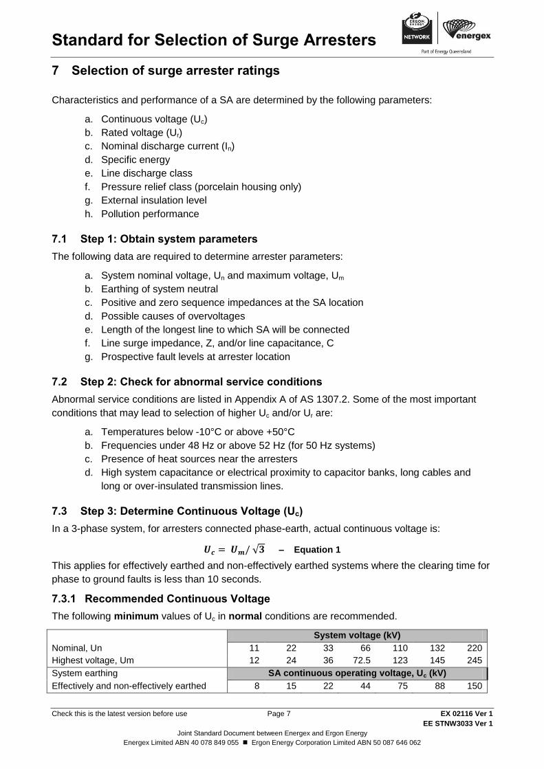
7.3 Step 3: Determine Continuous Voltage (Uc)
In a 3-phase system, for arresters connected phase-earth, actual continuous voltage is:
√ – Equation 1
This applies for effectively earthed and non-effectively earthed systems where the clearing time for
phase to ground faults is less than 10 seconds.
7.3.1 Recommended Continuous Voltage
The following minimum values of Uc in normal conditions are recommended.
Nominal, Un
System voltage (kV)
11 22 33 66 110 132 220
Highest voltage, Um 12 24 36 72.5 123 145 245
System earthing SA continuous operating voltage, Uc (kV)
Effectively and non-effectively earthed 8 15 22 44 75 88 150
Standard for Selection of Surge Arresters
Check this is the latest version before use Page 8 EX 02116 Ver 1
EE STNW3033 Ver 1
Joint Standard Document between Energex and Ergon Energy
Energex Limited ABN 40 078 849 055 Ergon Energy Corporation Limited ABN 50 087 646 062
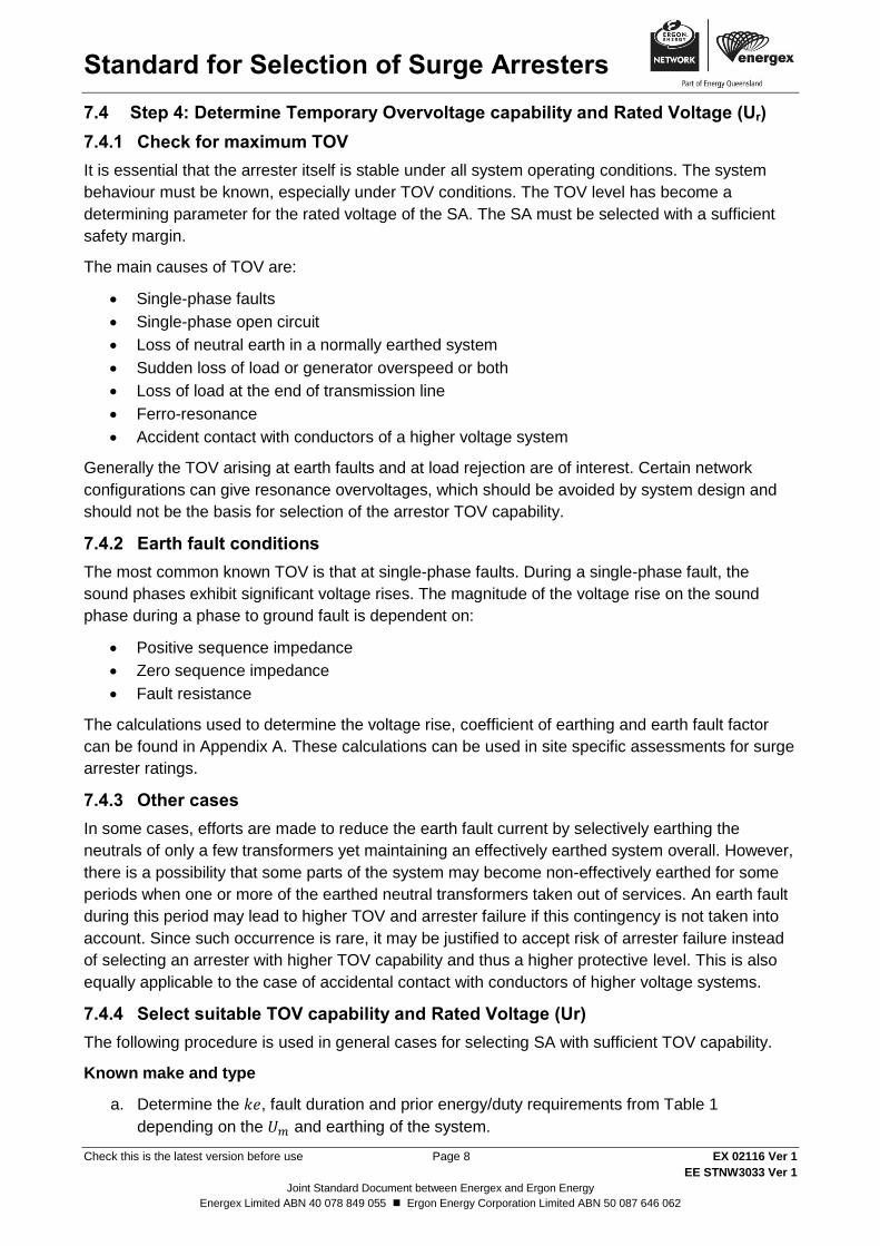
7.4 Step 4: Determine Temporary Overvoltage capability and Rated Voltage (Ur)
7.4.1 Check for maximum TOV
It is essential that the arrester itself is stable under all system operating conditions. The system
behaviour must be known, especially under TOV conditions. The TOV level has become a
determining parameter for the rated voltage of the SA. The SA must be selected with a sufficient
safety margin.
The main causes of TOV are:
Single-phase faults
Single-phase open circuit
Loss of neutral earth in a normally earthed system
Sudden loss of load or generator overspeed or both
Loss of load at the end of transmission line
Ferro-resonance
Accident contact with conductors of a higher voltage system
Generally the TOV arising at earth faults and at load rejection are of interest. Certain network
configurations can give resonance overvoltages, which should be avoided by system design and
should not be the basis for selection of the arrestor TOV capability.
7.4.2 Earth fault conditions
The most common known TOV is that at single-phase faults. During a single-phase fault, the
sound phases exhibit significant voltage rises. The magnitude of the voltage rise on the sound
phase during a phase to ground fault is dependent on:
Positive sequence impedance
Zero sequence impedance
Fault resistance
The calculations used to determine the voltage rise, coefficient of earthing and earth fault factor
can be found in Appendix A. These calculations can be used in site specific assessments for surge
arrester ratings.
7.4.3 Other cases
In some cases, efforts are made to reduce the earth fault current by selectively earthing the
neutrals of only a few transformers yet maintaining an effectively earthed system overall. However,
there is a possibility that some parts of the system may become non-effectively earthed for some
periods when one or more of the earthed neutral transformers taken out of services. An earth fault
during this period may lead to higher TOV and arrester failure if this contingency is not taken into
account. Since such occurrence is rare, it may be justified to accept risk of arrester failure instead
of selecting an arrester with higher TOV capability and thus a higher protective level. This is also
equally applicable to the case of accidental contact with conductors of higher voltage systems.
7.4.4 Select suitable TOV capability and Rated Voltage (Ur)
The following procedure is used in general cases for selecting SA with sufficient TOV capability.
Known make and type
a. Determine the , fault duration and prior energy/duty requirements from Table 1
depending on the and earthing of the system.
Standard for Selection of Surge Arresters
Check this is the latest version before use Page 9 EX 02116 Ver 1
EE STNW3033 Ver 1
Joint Standard Document between Energex and Ergon Energy
Energex Limited ABN 40 078 849 055 Ergon Energy Corporation Limited ABN 50 087 646 062
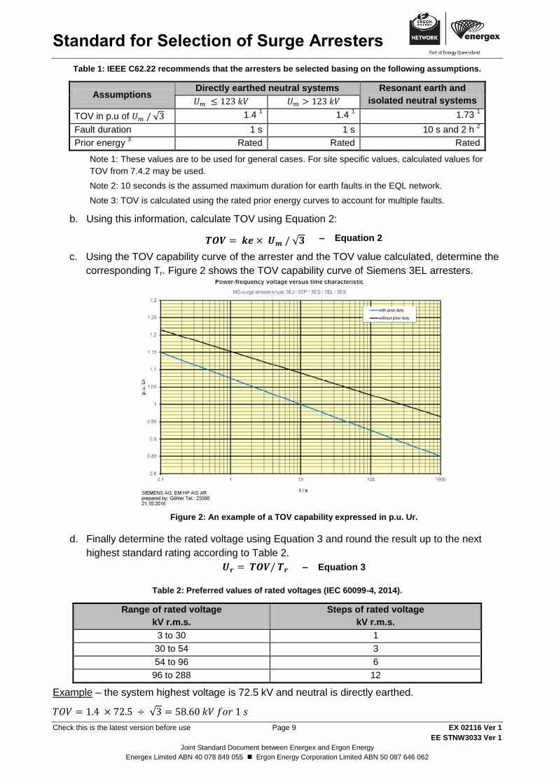
Table 1: IEEE C62.22 recommends that the arresters be selected basing on the following assumptions.
Assumptions Directly earthed neutral systems Resonant earth and
isolated neutral systems
TOV in p.u of √ 1.4
1 1.4
1 1.73
1
Fault duration 1 s 1 s 10 s and 2 h 2
Prior energy 3
Rated Rated Rated
Note 1: These values are to be used for general cases. For site specific values, calculated values for
TOV from 7.4.2 may be used.
Note 2: 10 seconds is the assumed maximum duration for earth faults in the EQL network.
Note 3: TOV is calculated using the rated prior energy curves to account for multiple faults.
b. Using this information, calculate TOV using Equation 2:
√ – Equation 2
c. Using the TOV capability curve of the arrester and the TOV value calculated, determine the
corresponding Tr. Figure 2 shows the TOV capability curve of Siemens 3EL arresters.
Figure 2: An example of a TOV capability expressed in p.u. Ur.
d. Finally determine the rated voltage using Equation 3 and round the result up to the next
highest standard rating according to Table 2.
– Equation 3
Table 2: Preferred values of rated voltages (IEC 60099-4, 2014).
Range of rated voltage
kV r.m.s.
Steps of rated voltage
kV r.m.s.
3 to 30 1
30 to 54 3
54 to 96 6
96 to 288 12
Example – the system highest voltage is 72.5 kV and neutral is directly earthed.
√
Standard for Selection of Surge Arresters
Check this is the latest version before use Page 10 EX 02116 Ver 1
EE STNW3033 Ver 1
Joint Standard Document between Energex and Ergon Energy
Energex Limited ABN 40 078 849 055 Ergon Energy Corporation Limited ABN 50 087 646 062
Assuming the arrester has TOV capability shown in Figure 2. At 1 s with prior rated energy, the
curve gives then
The next higher standard rating is .
Unknown make and type
It is recommended that the rated voltage, Ur at least 1.25 times Uc should be selected when
possible. If this is a non-standard rating, choose the next highest rating.
7.5 Step 5: Determine nominal discharge current, In
Standard In values stipulated by IEC 60099.4 are 5 000 A, 10 000 A and 20 000 A.
It is recommended a minimum nominal discharge current of 10 kA should be used for
protection of equipment in substations. This corresponds to Substation SL & SM class in IEC
60099.4.
7.6 Step 6: Determine energy withstand capability and specific energy
7.6.1 General
Switching overvoltage represents the most severe stress for arresters because of the very large
energies involved. The most onerous case is the stress caused by switching-in against a trapped
charge on a transmission line on arresters installed at the open far end of the line.
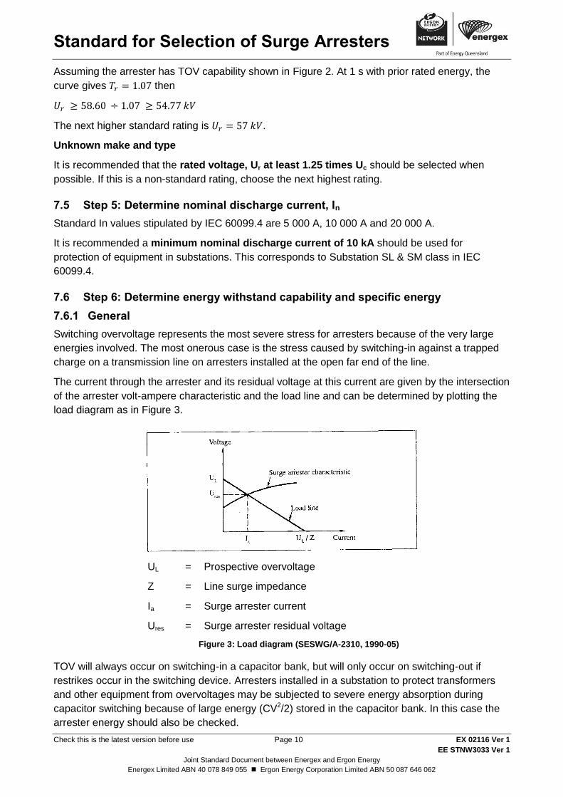
The current through the arrester and its residual voltage at this current are given by the intersection
of the arrester volt-ampere characteristic and the load line and can be determined by plotting the
load diagram as in Figure 3.
UL = Prospective overvoltage
Z = Line surge impedance
Ia = Surge arrester current
Ures = Surge arrester residual voltage
Figure 3: Load diagram (SESWG/A-2310, 1990-05)
TOV will always occur on switching-in a capacitor bank, but will only occur on switching-out if
restrikes occur in the switching device. Arresters installed in a substation to protect transformers
and other equipment from overvoltages may be subjected to severe energy absorption during
capacitor switching because of large energy (CV2/2) stored in the capacitor bank. In this case the
arrester energy should also be checked.
Standard for Selection of Surge Arresters
Check this is the latest version before use Page 11 EX 02116 Ver 1
EE STNW3033 Ver 1
Joint Standard Document between Energex and Ergon Energy
Energex Limited ABN 40 078 849 055 Ergon Energy Corporation Limited ABN 50 087 646 062
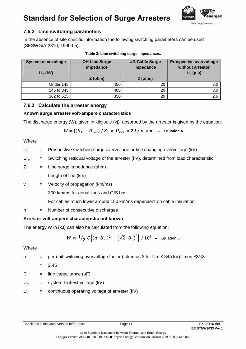
7.6.2 Line switching parameters
In the absence of site specific information the following switching parameters can be used
(SESWG/A-2310, 1990-05).
Table 3: Line switching surge impedances.
System max voltage
Um (kV)
OH Line Surge
impedance
Z (ohm)
UG Cable Surge
impedance
Z (ohm)
Prospective overvoltage
without arrestor
UL (p.u)
Under 145 450 20 3.0
145 to 345 400 20 3.0
362 to 525 350 20 2.6
7.6.3 Calculate the arrester energy
Known surge arrester volt-ampere characteristics
The discharge energy (W), given in kilojoule (kj), absorbed by the arrester is given by the equation:
[( ) ] – Equation 4
Where
UL = Prospective switching surge overvoltage or line changing overvoltage (kV)
Ures = Switching residual voltage of the arrester (kV), determined from load characteristic
Z = Line surge impedance (ohm)
l = Length of line (km)
v = Velocity of propagation (km/ms)
300 km/ms for aerial lines and GIS bus
For cables much lower around 150 km/ms dependent on cable insulation
n = Number of consecutive discharges
Arrester volt-ampere characteristic not known
The energy W in (kJ) can also be calculated from the following equation:
⁄ [( ) (√ ) ] – Equation 5
Where
a = per unit switching overvoltage factor (taken as 3 for Um ≤ 345 kV) times √2/√3
= 2.45
C = line capacitance (µF)
Um = system highest voltage (kV)
Uc = continuous operating voltage of arrester (kV)
Standard for Selection of Surge Arresters
Check this is the latest version before use Page 12 EX 02116 Ver 1
EE STNW3033 Ver 1
Joint Standard Document between Energex and Ergon Energy
Energex Limited ABN 40 078 849 055 Ergon Energy Corporation Limited ABN 50 087 646 062
7.6.4 Determine specific energy
( ) – Equation 6
7.7 Step 7: Arrester class
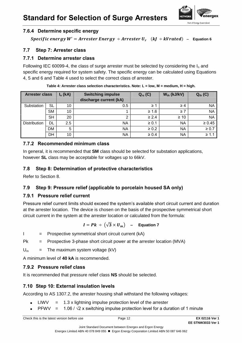
7.7.1 Determine arrester class
Following IEC 60099-4, the class of surge arrester must be selected by considering the In and
specific energy required for system safety. The specific energy can be calculated using Equations
4, 5 and 6 and Table 4 used to select the correct class of arrester.
Table 4: Arrester class selection characteristics. Note: L = low, M = medium, H = high.
Arrester class In (kA) Switching impulse
discharge current (kA)
Qrs (C) Wth (kJ/kV) Qth (C)
Substation SL 10 0.5 ≥ 1 ≥ 4 NA
SM 10 1 ≥ 1.6 ≥ 7 NA
SH 20 2 ≥ 2.4 ≥ 10 NA
Distribution DL 2.5 NA ≥ 0.1 NA ≥ 0.45
DM 5 NA ≥ 0.2 NA ≥ 0.7
DH 10 NA ≥ 0.4 NA ≥ 1.1
7.7.2 Recommended minimum class
In general, it is recommended that SM class should be selected for substation applications,
however SL class may be acceptable for voltages up to 66kV.
7.8 Step 8: Determination of protective characteristics
Refer to Section 8.
7.9 Step 9: Pressure relief (applicable to porcelain housed SA only)
7.9.1 Pressure relief current
Pressure relief current limits should exceed the system’s available short circuit current and duration
at the arrester location. The device is chosen on the basis of the prospective symmetrical short
circuit current in the system at the arrester location or calculated from the formula:
(√ ) – Equation 7
I = Prospective symmetrical short circuit current (kA)
Pk = Prospective 3-phase short circuit power at the arrester location (MVA)
Um = The maximum system voltage (kV)
A minimum level of 40 kA is recommended.
7.9.2 Pressure relief class
It is recommended that pressure relief class NS should be selected.
7.10 Step 10: External insulation levels
According to AS 1307.2, the arrester housing shall withstand the following voltages:
LIWV = 1.3 x lightning impulse protection level of the arrester
PFWV = 1.06 / √2 x switching impulse protection level for a duration of 1 minute
Standard for Selection of Surge Arresters
Check this is the latest version before use Page 13 EX 02116 Ver 1
EE STNW3033 Ver 1
Joint Standard Document between Energex and Ergon Energy
Energex Limited ABN 40 078 849 055 Ergon Energy Corporation Limited ABN 50 087 646 062
SIWV = 1.25 x switching impulse protection level for arresters having Ur ≥ 200 kV.
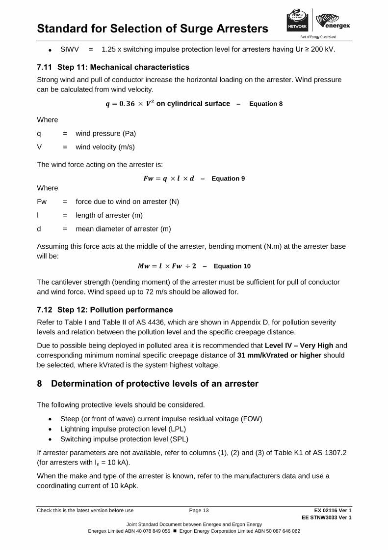
7.11 Step 11: Mechanical characteristics
Strong wind and pull of conductor increase the horizontal loading on the arrester. Wind pressure
can be calculated from wind velocity.
on cylindrical surface – Equation 8
Where
q = wind pressure (Pa)
V = wind velocity (m/s)
The wind force acting on the arrester is:
– Equation 9
Where
Fw = force due to wind on arrester (N)
l = length of arrester (m)
d = mean diameter of arrester (m)
Assuming this force acts at the middle of the arrester, bending moment (N.m) at the arrester base
will be:
– Equation 10
The cantilever strength (bending moment) of the arrester must be sufficient for pull of conductor
and wind force. Wind speed up to 72 m/s should be allowed for.
7.12 Step 12: Pollution performance
Refer to Table I and Table II of AS 4436, which are shown in Appendix D, for pollution severity
levels and relation between the pollution level and the specific creepage distance.
Due to possible being deployed in polluted area it is recommended that Level IV – Very High and
corresponding minimum nominal specific creepage distance of 31 mm/kVrated or higher should
be selected, where kVrated is the system highest voltage.
8 Determination of protective levels of an arrester
The following protective levels should be considered.
Steep (or front of wave) current impulse residual voltage (FOW)
Lightning impulse protection level (LPL)
Switching impulse protection level (SPL)
If arrester parameters are not available, refer to columns (1), (2) and (3) of Table K1 of AS 1307.2
(for arresters with In = 10 kA).
When the make and type of the arrester is known, refer to the manufacturers data and use a
coordinating current of 10 kApk.
Standard for Selection of Surge Arresters
Check this is the latest version before use Page 14 EX 02116 Ver 1
EE STNW3033 Ver 1
Joint Standard Document between Energex and Ergon Energy
Energex Limited ABN 40 078 849 055 Ergon Energy Corporation Limited ABN 50 087 646 062
8.1 Evaluating insulation co-ordination
Insulation coordination is evaluated on the basis of the margin between the insulation strength of
the surge voltage at the equipment terminals, which may be estimated by use of either Simplified
Method or method presented in Annex C of IEEE Std C62.22-1997, which is shown in Appendix B.
In general there are two methods of portraying insulation coordination
a. The tabulation of protective ratios or margins, and
b. The graphical presentation of coordination.
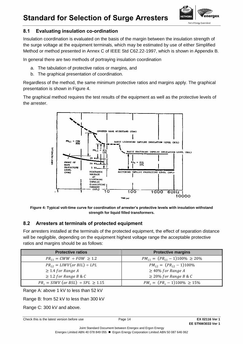
Regardless of the method, the same minimum protective ratios and margins apply. The graphical
presentation is shown in Figure 4.
The graphical method requires the test results of the equipment as well as the protective levels of
the arrester.
Figure 4: Typical volt-time curve for coordination of arrester’s protective levels with insulation withstand
strength for liquid filled transformers.
8.2 Arresters at terminals of protected equipment
For arresters installed at the terminals of the protected equipment, the effect of separation distance
will be negligible, depending on the equipment highest voltage range the acceptable protective
ratios and margins should be as follows:
Protective ratios Protective margins
( )
( )
( )
( ) ( )
Range A: above 1 kV to less than 52 kV
Range B: from 52 kV to less than 300 kV
Range C: 300 kV and above.
Standard for Selection of Surge Arresters
Check this is the latest version before use Page 15 EX 02116 Ver 1
EE STNW3033 Ver 1
Joint Standard Document between Energex and Ergon Energy
Energex Limited ABN 40 078 849 055 Ergon Energy Corporation Limited ABN 50 087 646 062
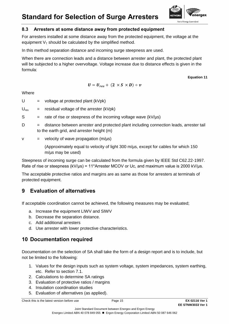
8.3 Arresters at some distance away from protected equipment
For arresters installed at some distance away from the protected equipment, the voltage at the
equipment VT should be calculated by the simplified method.
In this method separation distance and incoming surge steepness are used.
When there are connection leads and a distance between arrester and plant, the protected plant
will be subjected to a higher overvoltage. Voltage increase due to distance effects is given in the
formula:
Equation 11
( )
Where
U = voltage at protected plant (kVpk)
Ures = residual voltage of the arrester (kVpk)
S = rate of rise or steepness of the incoming voltage wave (kV/µs)
D = distance between arrester and protected plant including connection leads, arrester tail
to the earth grid, and arrester height (m)
v = velocity of wave propagation (m/µs)
(Approximately equal to velocity of light 300 m/µs, except for cables for which 150
m/µs may be used)
Steepness of incoming surge can be calculated from the formula given by IEEE Std C62.22-1997.
Rate of rise or steepness (kV/μs) = 11*Arrester MCOV or Uc, and maximum value is 2000 kV/μs.
The acceptable protective ratios and margins are as same as those for arresters at terminals of
protected equipment.
9 Evaluation of alternatives
If acceptable coordination cannot be achieved, the following measures may be evaluated;
a. Increase the equipment LIWV and SIWV
b. Decrease the separation distance.
c. Add additional arresters
d. Use arrester with lower protective characteristics.
10 Documentation required
Documentation on the selection of SA shall take the form of a design report and is to include, but
not be limited to the following:
1. Values for the design inputs such as system voltage, system impedances, system earthing,
etc. Refer to section 7.1.
2. Calculations to determine SA ratings
3. Evaluation of protective ratios / margins
4. Insulation coordination studies
5. Evaluation of alternatives (as applied).
Standard for Selection of Surge Arresters
Check this is the latest version before use Page 16 EX 02116 Ver 1
EE STNW3033 Ver 1
Joint Standard Document between Energex and Ergon Energy
Energex Limited ABN 40 078 849 055 Ergon Energy Corporation Limited ABN 50 087 646 062
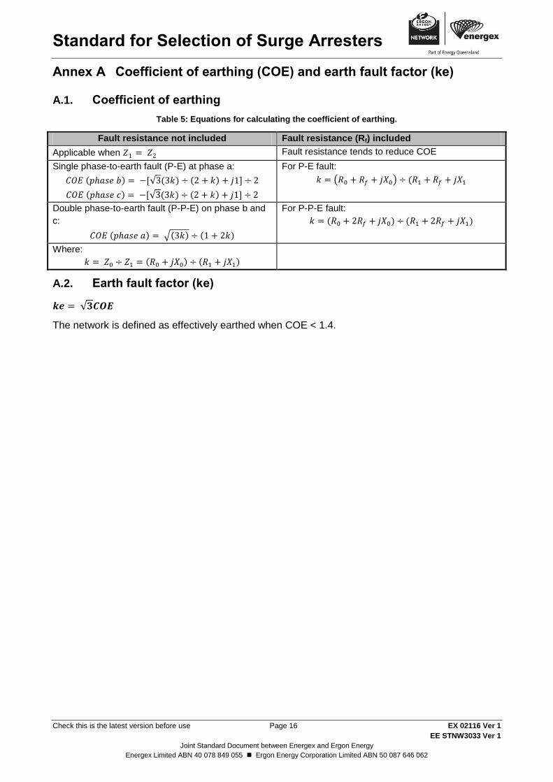
Coefficient of earthing (COE) and earth fault factor (ke) Annex A
A.1. Coefficient of earthing
Table 5: Equations for calculating the coefficient of earthing.
Fault resistance not included Fault resistance (Rf) included
Applicable when Fault resistance tends to reduce COE
Single phase-to-earth fault (P-E) at phase a:
( ) [√ ( ) ( ) ]
( ) [√ ( ) ( ) ]
For P-E fault:
( ) (
Double phase-to-earth fault (P-P-E) on phase b and
c:
( ) √( ) ( )
For P-P-E fault:
( ) ( )
Where:
( ) ( )
A.2. Earth fault factor (ke)
√
The network is defined as effectively earthed when COE < 1.4.
Standard for Selection of Surge Arresters
Check this is the latest version before use Page 17 EX 02116 Ver 1
EE STNW3033 Ver 1
Joint Standard Document between Energex and Ergon Energy
Energex Limited ABN 40 078 849 055 Ergon Energy Corporation Limited ABN 50 087 646 062
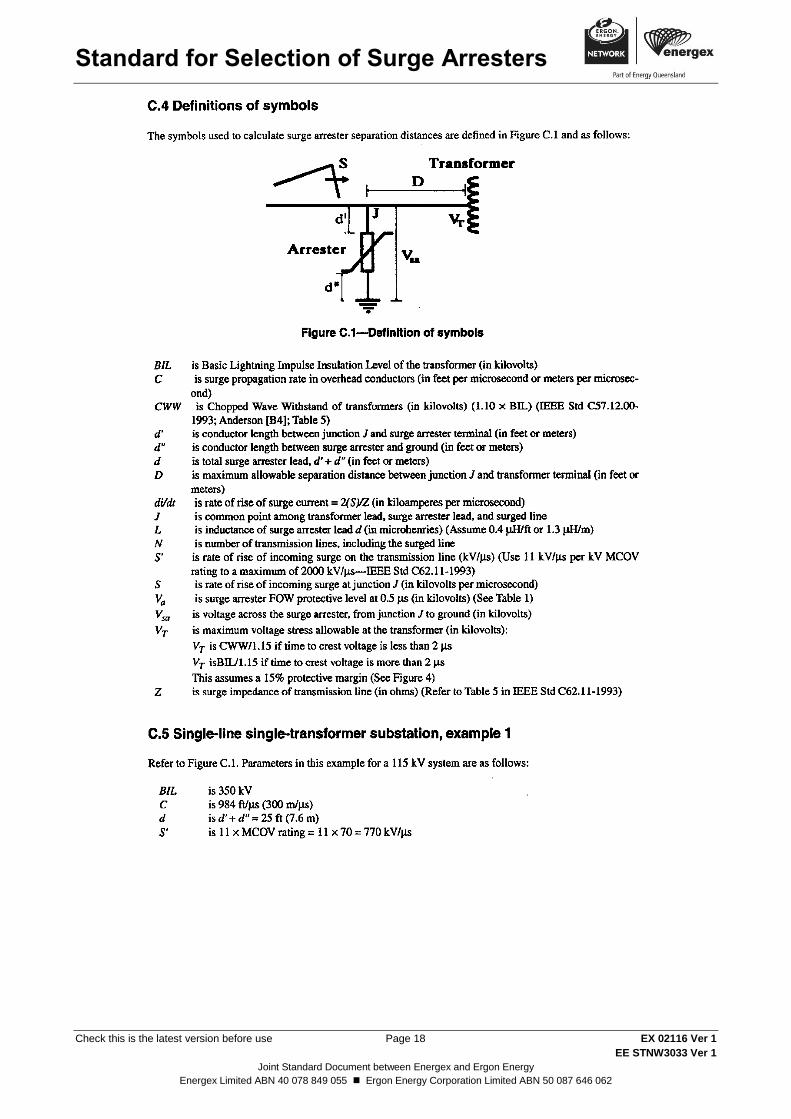
Annex C of IEEE Std C62.22-1997 Annex B
Standard for Selection of Surge Arresters
Check this is the latest version before use Page 18 EX 02116 Ver 1
EE STNW3033 Ver 1
Joint Standard Document between Energex and Ergon Energy
Energex Limited ABN 40 078 849 055 Ergon Energy Corporation Limited ABN 50 087 646 062
Standard for Selection of Surge Arresters
Check this is the latest version before use Page 19 EX 02116 Ver 1
EE STNW3033 Ver 1
Joint Standard Document between Energex and Ergon Energy
Energex Limited ABN 40 078 849 055 Ergon Energy Corporation Limited ABN 50 087 646 062
Standard for Selection of Surge Arresters
Check this is the latest version before use Page 20 EX 02116 Ver 1
EE STNW3033 Ver 1
Joint Standard Document between Energex and Ergon Energy
Energex Limited ABN 40 078 849 055 Ergon Energy Corporation Limited ABN 50 087 646 062
Standard for Selection of Surge Arresters
Check this is the latest version before use Page 21 EX 02116 Ver 1
EE STNW3033 Ver 1
Joint Standard Document between Energex and Ergon Energy
Energex Limited ABN 40 078 849 055 Ergon Energy Corporation Limited ABN 50 087 646 062
Standard for Selection of Surge Arresters
Check this is the latest version before use Page 22 EX 02116 Ver 1
EE STNW3033 Ver 1
Joint Standard Document between Energex and Ergon Energy
Energex Limited ABN 40 078 849 055 Ergon Energy Corporation Limited ABN 50 087 646 062
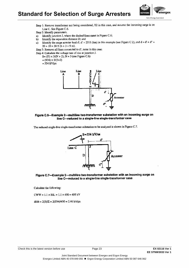
Standard for Selection of Surge Arresters
Check this is the latest version before use Page 23 EX 02116 Ver 1
EE STNW3033 Ver 1
Joint Standard Document between Energex and Ergon Energy
Energex Limited ABN 40 078 849 055 Ergon Energy Corporation Limited ABN 50 087 646 062
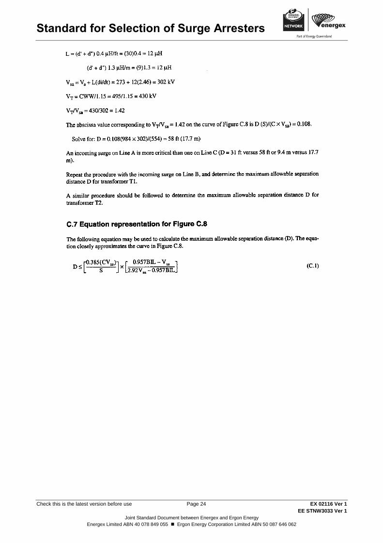
Standard for Selection of Surge Arresters
Check this is the latest version before use Page 24 EX 02116 Ver 1
EE STNW3033 Ver 1
Joint Standard Document between Energex and Ergon Energy
Energex Limited ABN 40 078 849 055 Ergon Energy Corporation Limited ABN 50 087 646 062
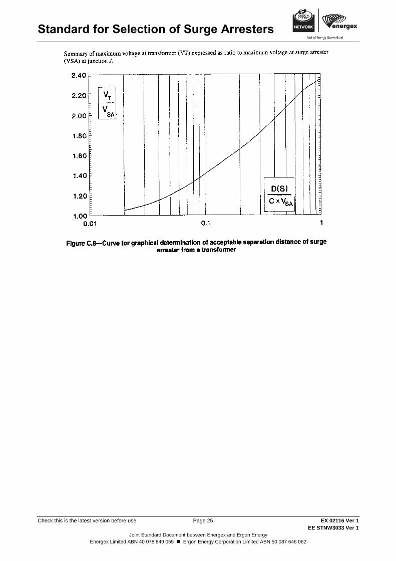
Standard for Selection of Surge Arresters
Check this is the latest version before use Page 25 EX 02116 Ver 1
EE STNW3033 Ver 1
Joint Standard Document between Energex and Ergon Energy
Energex Limited ABN 40 078 849 055 Ergon Energy Corporation Limited ABN 50 087 646 062
Standard for Selection of Surge Arresters
Check this is the latest version before use Page 26 EX 02116 Ver 1
EE STNW3033 Ver 1
Joint Standard Document between Energex and Ergon Energy
Energex Limited ABN 40 078 849 055 Ergon Energy Corporation Limited ABN 50 087 646 062
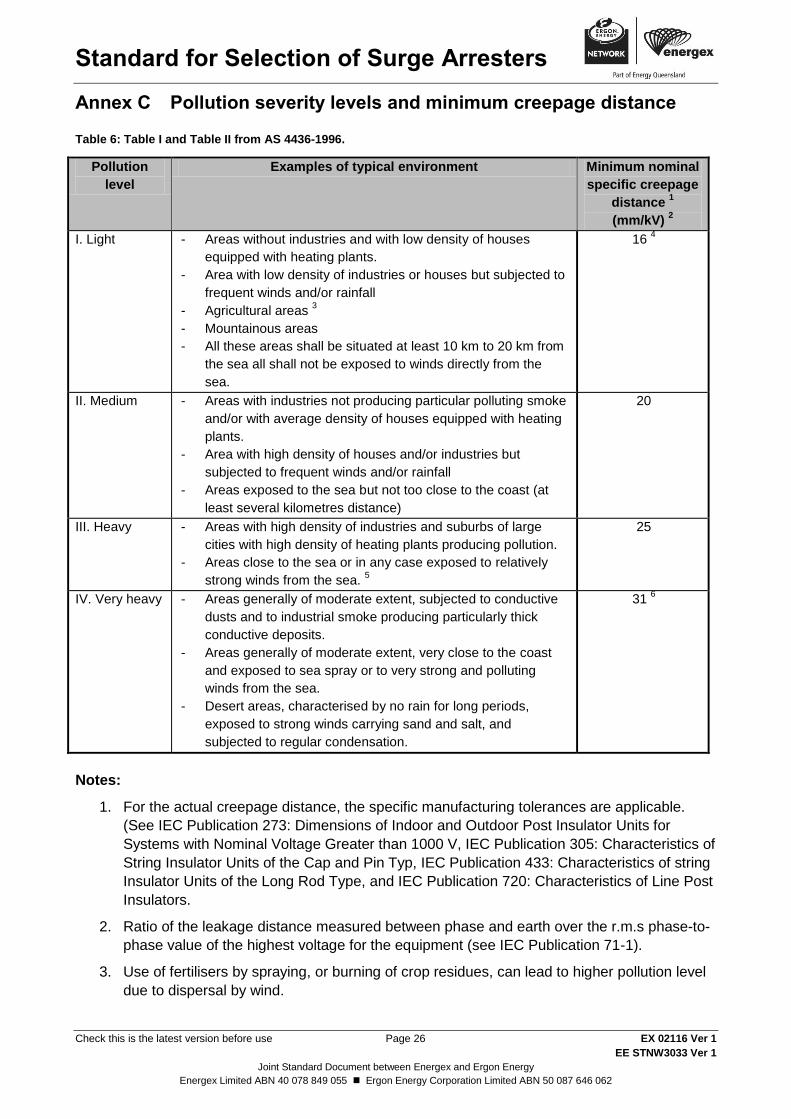
Pollution severity levels and minimum creepage distance Annex C
Table 6: Table I and Table II from AS 4436-1996.
Pollution
level
Examples of typical environment Minimum nominal
specific creepage
distance 1
(mm/kV) 2
I. Light - Areas without industries and with low density of houses
equipped with heating plants.
- Area with low density of industries or houses but subjected to
frequent winds and/or rainfall
- Agricultural areas 3
- Mountainous areas
- All these areas shall be situated at least 10 km to 20 km from
the sea all shall not be exposed to winds directly from the
sea.
16 4
II. Medium - Areas with industries not producing particular polluting smoke
and/or with average density of houses equipped with heating
plants.
- Area with high density of houses and/or industries but
subjected to frequent winds and/or rainfall
- Areas exposed to the sea but not too close to the coast (at
least several kilometres distance)
20
III. Heavy - Areas with high density of industries and suburbs of large
cities with high density of heating plants producing pollution.
- Areas close to the sea or in any case exposed to relatively
strong winds from the sea. 5
25
IV. Very heavy - Areas generally of moderate extent, subjected to conductive
dusts and to industrial smoke producing particularly thick
conductive deposits.
- Areas generally of moderate extent, very close to the coast
and exposed to sea spray or to very strong and polluting
winds from the sea.
- Desert areas, characterised by no rain for long periods,
exposed to strong winds carrying sand and salt, and
subjected to regular condensation.
31 6
Notes:
1. For the actual creepage distance, the specific manufacturing tolerances are applicable.
(See IEC Publication 273: Dimensions of Indoor and Outdoor Post Insulator Units for
Systems with Nominal Voltage Greater than 1000 V, IEC Publication 305: Characteristics of
String Insulator Units of the Cap and Pin Typ, IEC Publication 433: Characteristics of string
Insulator Units of the Long Rod Type, and IEC Publication 720: Characteristics of Line Post
Insulators.
2. Ratio of the leakage distance measured between phase and earth over the r.m.s phase-to-
phase value of the highest voltage for the equipment (see IEC Publication 71-1).
3. Use of fertilisers by spraying, or burning of crop residues, can lead to higher pollution level
due to dispersal by wind.
Standard for Selection of Surge Arresters
Check this is the latest version before use Page 27 EX 02116 Ver 1
EE STNW3033 Ver 1
Joint Standard Document between Energex and Ergon Energy
Energex Limited ABN 40 078 849 055 Ergon Energy Corporation Limited ABN 50 087 646 062
4. In very lightly polluted areas, specific nominal creepage distances lower than 16 mm/kV
can be used depending on service experience, 12 mm/kV seems to be a lower limit.
5. Distances from sea depend on the topography of the coastal area and on the extreme wind
conditions.
6. In the case of exceptional pollution severity, a specific nominal creepage distance of 31
mm/kV may not be adequate. Depending on service experience and/or on laboratory test
results, a higher value of specific creepage distance can be used, but in some instances
the practicability of washing or greasing may be considered.
Standard for Selection of Surge Arresters
Check this is the latest version before use Page 28 EX 02116 Ver 1
EE STNW3033 Ver 1
Joint Standard Document between Energex and Ergon Energy
Energex Limited ABN 40 078 849 055 Ergon Energy Corporation Limited ABN 50 087 646 062
How to use EQL Selection of Surge Arresters Workbook: Annex D
To assist with the selection of appropriate surge arresters, a selection tool has been created based
on the information in this standard. The tool is made up of seven sheets containing useful
information and formulas, prefilled data, input data and calculations. In order to complete SA
evaluation, only the two green coloured sheets need to be accessed as these contain the input
data and calculated answers. A brief description of each sheet will be provided below.
D.1. Title
The title sheet contains the revision history of the document and a table of contents describing
each sheet of the workbook.
D.2. Useful Information
This sheet provides information about the standards used to develop the spreadsheet and a
number of other pieces of background information which were used in the calculations in sheets 4
and 5. These include descriptions of appropriate insulation levels for different voltages, surge
arrester characteristics, insulation coordination, system overvoltage, pollution levels and other
miscellaneous information.
D.3. Useful Formulae
The useful formulae sheet contains several formulae that have been used to calculate results in
sheets 4 and 5 as well as some that were not used but could be useful if further calculations were
required to select an appropriate SA. These formulae include impedance, velocity of surge
propagation, coefficient of earthing, phase-to-earth faults, earth fault factor and the energy
generated in an arrester.
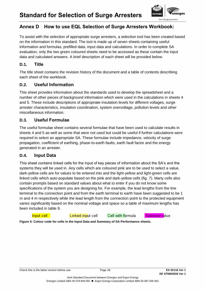
D.4. Input Data
This sheet contains linked cells for the input of key pieces of information about the SA’s and the
systems they will be used in. Any cells which are coloured pink are to be used to select a value,
dark-yellow cells are for values to be entered into and the light-yellow and light-green cells are
linked cells which auto-populate based on the pink and dark-yellow cells (fig. 7). Many cells also
contain prompts based on standard values about what to enter if you do not know some
specifications of the system you are designing for. For example, the lead lengths from the line
terminal to the connection point and from the earth terminal to earth have been suggested to be 1
m and 4 m respectively while the lead length from the connection point to the protected equipment
varies significantly based on the nominal voltage and space so a table of maximum lengths has
been included in table 9.
Figure 5: Colour code for cells in the Input Data and Summary of SA Performance sheets.
Standard for Selection of Surge Arresters
Check this is the latest version before use Page 29 EX 02116 Ver 1
EE STNW3033 Ver 1
Joint Standard Document between Energex and Ergon Energy
Energex Limited ABN 40 078 849 055 Ergon Energy Corporation Limited ABN 50 087 646 062
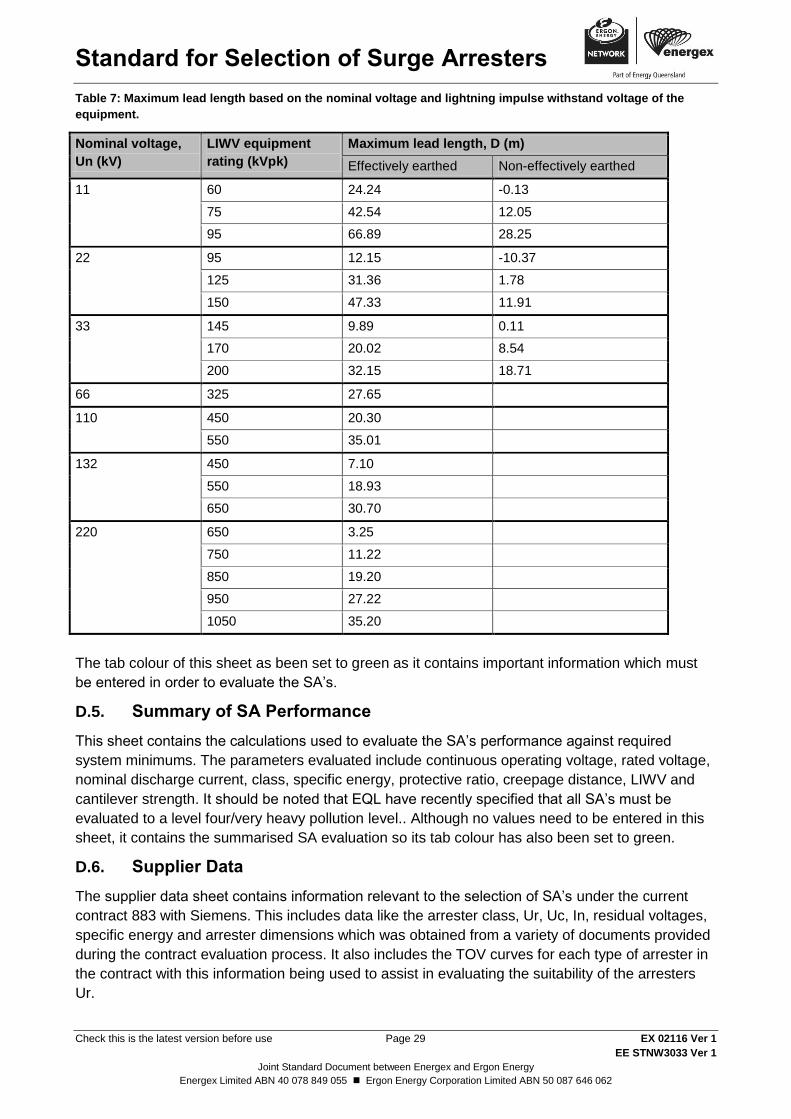
Table 7: Maximum lead length based on the nominal voltage and lightning impulse withstand voltage of the
equipment.
Nominal voltage,
Un (kV)
LIWV equipment
rating (kVpk)
Maximum lead length, D (m)
Effectively earthed Non-effectively earthed
11 60 24.24 -0.13
75 42.54 12.05
95 66.89 28.25
22 95 12.15 -10.37
125 31.36 1.78
150 47.33 11.91
33 145 9.89 0.11
170 20.02 8.54
200 32.15 18.71
66 325 27.65
110 450 20.30
550 35.01
132 450 7.10
550 18.93
650 30.70
220 650 3.25
750 11.22
850 19.20
950 27.22
1050 35.20
The tab colour of this sheet as been set to green as it contains important information which must
be entered in order to evaluate the SA’s.
D.5. Summary of SA Performance
This sheet contains the calculations used to evaluate the SA’s performance against required
system minimums. The parameters evaluated include continuous operating voltage, rated voltage,
nominal discharge current, class, specific energy, protective ratio, creepage distance, LIWV and
cantilever strength. It should be noted that EQL have recently specified that all SA’s must be
evaluated to a level four/very heavy pollution level.. Although no values need to be entered in this
sheet, it contains the summarised SA evaluation so its tab colour has also been set to green.
D.6. Supplier Data
The supplier data sheet contains information relevant to the selection of SA’s under the current
contract 883 with Siemens. This includes data like the arrester class, Ur, Uc, In, residual voltages,
specific energy and arrester dimensions which was obtained from a variety of documents provided
during the contract evaluation process. It also includes the TOV curves for each type of arrester in
the contract with this information being used to assist in evaluating the suitability of the arresters
Ur.
Standard for Selection of Surge Arresters
Check this is the latest version before use Page 30 EX 02116 Ver 1
EE STNW3033 Ver 1
Joint Standard Document between Energex and Ergon Energy
Energex Limited ABN 40 078 849 055 Ergon Energy Corporation Limited ABN 50 087 646 062
D.7. Lookup Tables
The final sheet contains information which is used in sheet 4 to create the drop-down menus in the
pink cells. It does not need to be accessed unless changes need to be made to the spreadsheet or
there is an issue with what is being displayed.
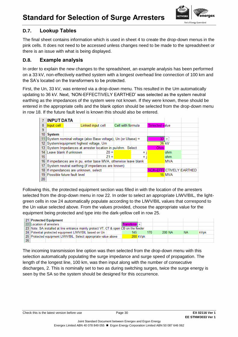
D.8. Example analysis
In order to explain the new changes to the spreadsheet, an example analysis has been performed
on a 33 kV, non-effectively earthed system with a longest overhead line connection of 100 km and
the SA’s located on the transformers to be protected.
First, the Un, 33 kV, was entered via a drop-down menu. This resulted in the Um automatically
updating to 36 kV. Next, ‘NON-EFFECTIVELY EARTHED’ was selected as the system neutral
earthing as the impedances of the system were not known. If they were known, these should be
entered in the appropriate cells and the blank option should be selected from the drop-down menu
in row 18. If the future fault level is known this should also be entered.
Following this, the protected equipment section was filled in with the location of the arresters
selected from the drop-down menu in row 22. In order to select an appropriate LIWV/BIL, the light-
green cells in row 24 automatically populate according to the LIWV/BIL values that correspond to
the Un value selected above. From the values provided, choose the appropriate value for the
equipment being protected and type into the dark-yellow cell in row 25.
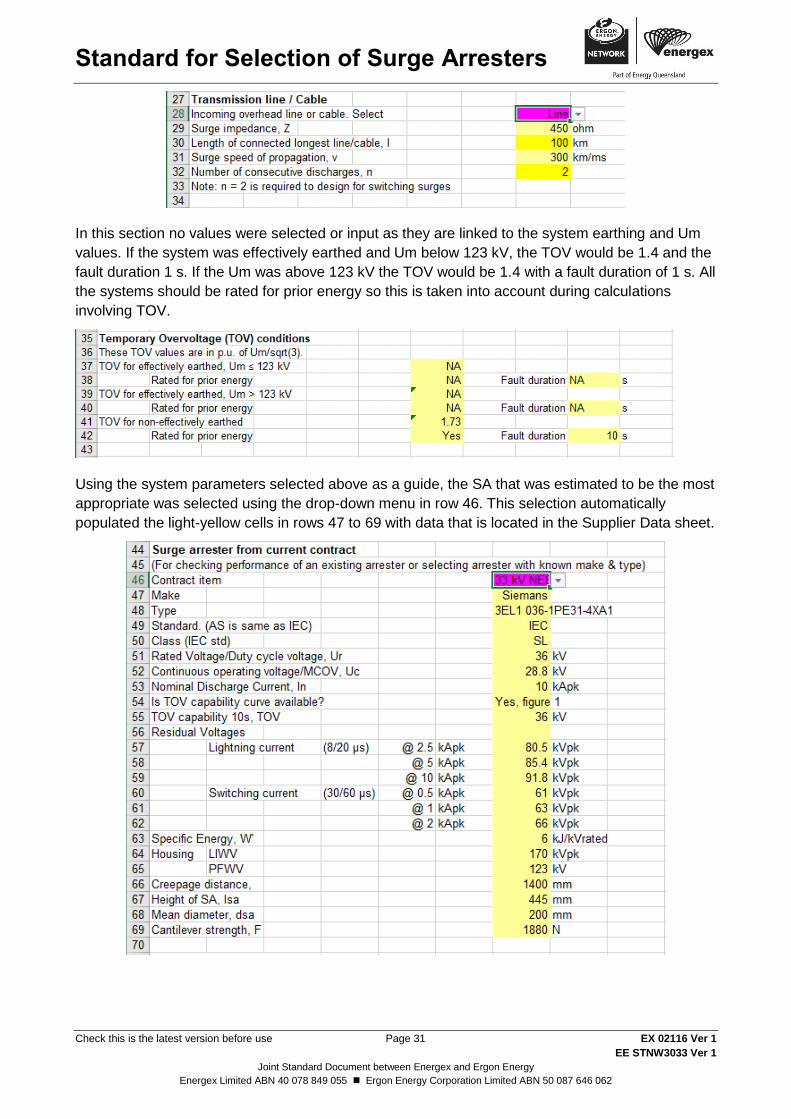
The incoming transmission line option was then selected from the drop-down menu with this
selection automatically populating the surge impedance and surge speed of propagation. The
length of the longest line, 100 km, was then input along with the number of consecutive
discharges, 2. This is nominally set to two as during switching surges, twice the surge energy is
seen by the SA so the system should be designed for this occurrence.
Standard for Selection of Surge Arresters
Check this is the latest version before use Page 31 EX 02116 Ver 1
EE STNW3033 Ver 1
Joint Standard Document between Energex and Ergon Energy
Energex Limited ABN 40 078 849 055 Ergon Energy Corporation Limited ABN 50 087 646 062
In this section no values were selected or input as they are linked to the system earthing and Um
values. If the system was effectively earthed and Um below 123 kV, the TOV would be 1.4 and the
fault duration 1 s. If the Um was above 123 kV the TOV would be 1.4 with a fault duration of 1 s. All
the systems should be rated for prior energy so this is taken into account during calculations
involving TOV.
Using the system parameters selected above as a guide, the SA that was estimated to be the most
appropriate was selected using the drop-down menu in row 46. This selection automatically
populated the light-yellow cells in rows 47 to 69 with data that is located in the Supplier Data sheet.
Standard for Selection of Surge Arresters
Check this is the latest version before use Page 32 EX 02116 Ver 1
EE STNW3033 Ver 1
Joint Standard Document between Energex and Ergon Energy
Energex Limited ABN 40 078 849 055 Ergon Energy Corporation Limited ABN 50 087 646 062
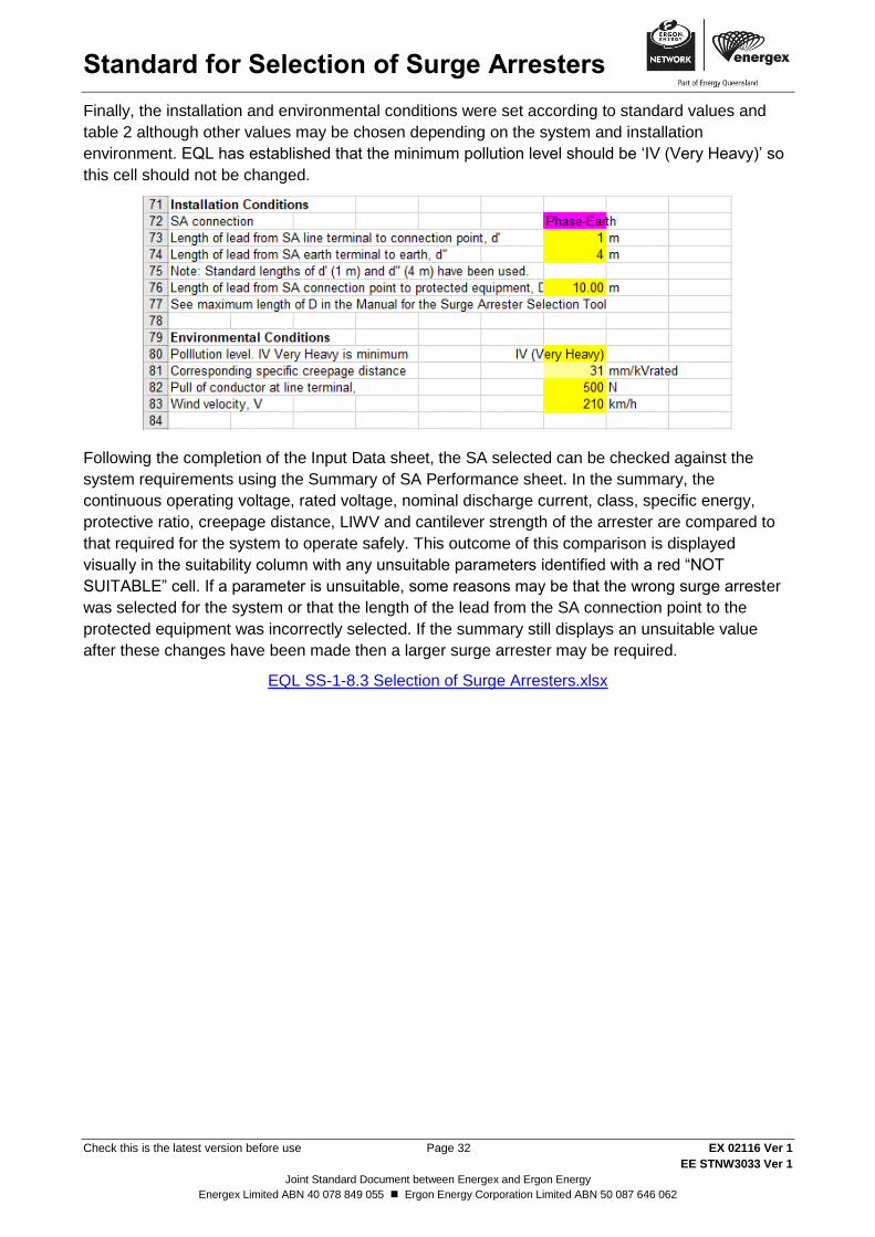
Finally, the installation and environmental conditions were set according to standard values and
table 2 although other values may be chosen depending on the system and installation
environment. EQL has established that the minimum pollution level should be ‘IV (Very Heavy)’ so
this cell should not be changed.
Following the completion of the Input Data sheet, the SA selected can be checked against the
system requirements using the Summary of SA Performance sheet. In the summary, the
continuous operating voltage, rated voltage, nominal discharge current, class, specific energy,
protective ratio, creepage distance, LIWV and cantilever strength of the arrester are compared to
that required for the system to operate safely. This outcome of this comparison is displayed
visually in the suitability column with any unsuitable parameters identified with a red “NOT
SUITABLE” cell. If a parameter is unsuitable, some reasons may be that the wrong surge arrester
was selected for the system or that the length of the lead from the SA connection point to the
protected equipment was incorrectly selected. If the summary still displays an unsuitable value
after these changes have been made then a larger surge arrester may be required.
EQL SS-1-8.3 Selection of Surge Arresters.xlsx
Recommended