English
AM
M D Y Y Y Y
MIN
ST8-WiFi TimerInstallation Guide and Operations Manual
II
ContentsIntroduction
Welcome to Rain Bird ...................................... 1Timer Features ................................................. 1Controls and Indicators ................................... 1
Key Functions .....................................................................1
InstallationTools and Supplies Needed ............................. 2Mount Timer .................................................... 2Wiring Connections ......................................... 3
Connect Zone Valves ......................................................3Valve Connections .......................................................3Timer Connections ......................................................3
Optional Accessories ......................................................4Master Valve....................................................................4Pump Start Relay ..........................................................4Rain Sensor .....................................................................5
Install Batteries ............................................... 5Connect Power ................................................. 5
Indoor Timer .......................................................................5Outdoor Timer ...................................................................6
App ProgrammingActivate Hotspot ............................................. 7Launch the Rain Bird App ............................... 7
Programming at the TimerDate/Time ........................................................ 7Watering Schedule .......................................... 8
Select Zone .....................................................................8Set Watering Run Times ............................................8Set Watering Start Times ..........................................8Set Watering Start Days ............................................8Custom Days ................................................................9Odd Days .......................................................................9
Even Days ......................................................................9Cyclic Days ................................................................. 10
Options and Special FeaturesRain Delay ...................................................... 10Copy Zone to Zone ........................................ 10
Normal OperationAuto ............................................................... 11O� .................................................................. 11
Additional FeaturesWater Now ..................................................... 12
Water ALL Zones: ........................................................... 12Water ONE Zone: ........................................................... 12
Seasonal Adjust ............................................. 13
TroubleshootingError Detection .............................................. 14Connection Issues ......................................... 14Watering Issues ............................................. 15Electrical Issues ............................................. 15
ST8-WiFi TimerInstallation Guide and Operations Manual
Symbols
NOTE: Alerts user to important operating functionality or installation instructions.
WARNING: Alerts user to the presence of electricity which may pose a risk of shock or other hazard.
For help setting up or operating the ST8-WiFi Timer, please call Rain Bird toll-free
Technical Support at:
1-800- RAIN BIRD (800-724-6247) or visit www.rainbird.com
III
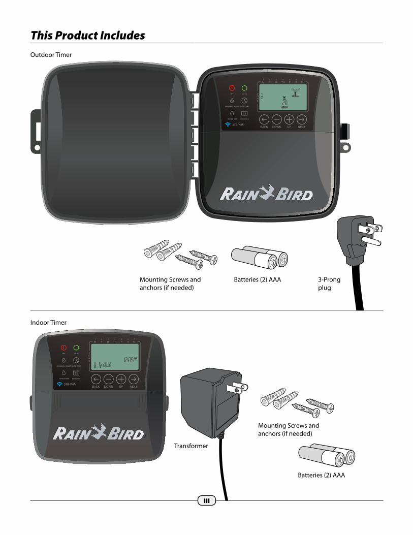
This Product Includes
AM
M D Y Y Y Y
MIN
Outdoor Timer
Mounting Screws and anchors (if needed)
Mounting Screws and anchors (if needed)
Batteries (2) AAA
Indoor Timer
Batteries (2) AAA
Transformer
3-Prong plug

1
ESP-RZX
Z
O
N
E
OFF
AUTO
T
2
W
3
TH
4
F
5
S
6
SU
7
M
1
DATE/TIME
SCHEDULEMANUAL
SEASONAL
ADJUST
BACK OFF ON NEXT
AM
M D Y Y Y Y
AM
M D Y Y Y Y
Introduction
Welcome to Intelligent Watering!Thank you for purchasing a WiFi-enabled Smart Timer from Rain Bird, a trusted name in irrigation throughout the world for over 80 years.
In this manual are step by step instructions for how to install and operate your timer.
Display ScreenDisplays programming information and irrigation status.
Next/Back ButtonsSelect programming options.
OFFCancel all active watering immediately and disable automatic irrigation.
Seasonal AdjustIncrease or decrease watering duration (Run Times) for all Zones.
Water NowStart watering immediately for all Zones in sequence, or for any single Zone.
Watering ScheduleCreate customized irrigation schedules to run automatically at speci�c times, durations and intervals.
AUTOWatering occurs automatically according to programmed schedules.
Timer FeaturesThe Timer has a variety of advanced water management features, including:
• Zone based programming allows independent irrigation scheduling for di�erent areas (Zones), based on the speci�c water requirements for each area.
• Programs can be set to water on selected days of the week, odd or even calendar days, or at custom intervals, allowing enhanced �exibility and control of irrigation schedules.
• Multiple Watering Start Times allow you to run the same program multiple times on the same day.
• Seasonal Adjust allows quick adjustment of watering duration based on weather or other conditions.
• Manual Water feature to allow immediate watering of all Zones or one Zone at a time.
Timer manual interface controls and indicators.The manual timer interface allows for visual con�rmation of schedule as well as custom programming when a mobile device is not available.
Key Functions
Date/TimeSet the current Date and Time.
NOTE: Press and HOLD + or – to accelerate setting adjustments.
+ or – ButtonsAdjust program settings.

2
Installation
Tools and Supplies Needed• Phillips screwdriver
• Wire stripper
• Hammer
• Valve wire: direct burial, color coded multi-strand (not included)
• 18 gauge for runs less than 800 feet.
• 14 gauge for runs greater than 800 feet.
• Watertight splice connectors (not included)
Before Removing Old Timer
24VAC SENSOR COM 1 2 3 4 5 6
AT&T
100%
4:21 PM
AT&TAT&TA
100%
4:21 PM
AT&T
100%
4:21 PM
AT&TAT&TA
A. Check WiFi signal
With your phone, check WiFi signal strength of your timer’s location (2 bars minimum is recommended). Boost signal if needed by adding a wireless router or moving the timer and router closer together.
B. Take A Photo of Wiring Details
This photo will be useful reference when installing the new timer.
Record Current Watering Times
Zone Days Per Week Duration 1 Mo, We, Fr 20 minutes
THEN UNPLUG TRANSFORMER/TURN OFF POWER AND REMOVE WIRES.
Mount TimerMount the Timer in an accessible location
NOTE: Indoor models are for indoor use only. Outdoor models can be used indoors or outdoors.
NOTE: For indoor models, choose a location within 6 feet of an AC power outlet and at least 15 feet away from major appliances or air conditioners.
Drive a screw into the wall, leaving an 1/8" gap between the screw-head and the wall (use the supplied wall anchors if necessary).
Locate the keyhole slot on back of the unit and hang it securely on the screw.
Remove the wiring bay cover at the bottom of the unit and drive a second screw through the center hole at the bottom of the unit as shown (use the supplied wall anchors if necessary).
INDOOR MODEL
OUTDOOR MODEL
If hard wiring for AC power, remove knockout for conduit
CONNECT
120 VAC
1/8 IN.
1/8 IN.
A
B
3
24VACACCESSORY
SENS 1 2 3 4 5 6 7 8C M
RESET
TERMINAL BLOCK
DIRECT BURIAL CABLE
WIRES TO ZONES 3 & 4POWER
POWER
COMMON WIRE
WATER-TIGHT CONNECTORS
ZONE 1 VALVE
ZONE 2 VALVE
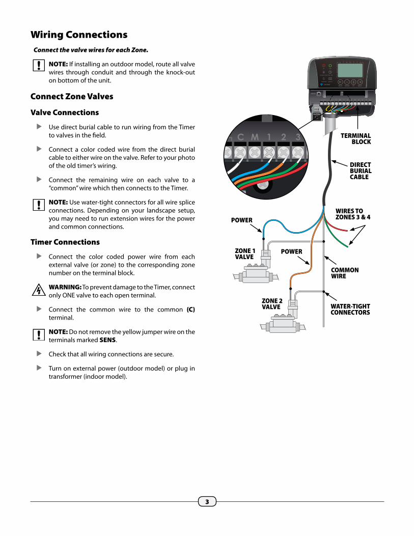
Wiring ConnectionsConnect the valve wires for each Zone.
NOTE: If installing an outdoor model, route all valve wires through conduit and through the knock-out on bottom of the unit.
Connect Zone Valves
Valve Connections
Use direct burial cable to run wiring from the Timer to valves in the �eld.
Connect a color coded wire from the direct burial cable to either wire on the valve. Refer to your photo of the old timer’s wiring.
Connect the remaining wire on each valve to a “common” wire which then connects to the Timer.
NOTE: Use water-tight connectors for all wire splice connections. Depending on your landscape setup, you may need to run extension wires for the power and common connections.
Timer Connections
Connect the color coded power wire from each external valve (or zone) to the corresponding zone number on the terminal block.
WARNING: To prevent damage to the Timer, connect only ONE valve to each open terminal.
Connect the common wire to the common (C) terminal.
NOTE: Do not remove the yellow jumper wire on the terminals marked SENS.
Check that all wiring connections are secure.
Turn on external power (outdoor model) or plug in transformer (indoor model).

4
Optional Accessories
Connect an optional Master Valve, Pump Start Relay or Rain Sensor to the Timer.
Master Valve
Timers support the use of a master valve.
Using a direct burial cable, connect one of the wires from the master valve (or pump start relay) to the master valve terminal (M).
Connect the remaining wire from the master valve (or pump start relay) to the common terminal (C).
24VACACCESSORY
SENS 1 2 3 4 5 6 7 8C M
RESET
MASTER VALVE
DIRECT BURIAL CABLE
POWER
COMMON
Pump Start Relay
Pumps are used in some places to draw water from a well or other source. If you are activating a pump from the Timer, you must install a pump start relay.
A pump start relay connects to the Timer in the same way as a Master Valve, but connects di�erently at the water source.
To avoid possible pump damage, connect a short jumper wire from any unused zone terminal(s) to the nearest zone terminal in use.
Example: If a 4 zone model Timer is in use with only two zones connected, route the terminals for zones 3 and 4 to the nearest active terminal (in this example, zone 2).
24VACACCESSORY
SENS 1 2 3 4 5 6 7 8C M
RESETACTIVE TERMINAL
JUMPER WIRES

5
Rain Sensor
Remove the wiring bay cover at the bottom of the unit.
Remove the yellow jumper wire from the terminals marked SENS on the terminal block.
24VACACCESSORY
SENS 1 2 3 4 5 6 7 8C M
RESET
REMOVE JUMPER WIRE
NOTE: Do not remove the jumper wire unless connecting a rain sensor. The Timer will not function if the jumper wire is removed and a rain sensor is not connected.
Connect the two wires from the sensor to the SENS terminals.
Install BatteriesThe Timer can keep the date and time in the event of a power outage if batteries are installed for backup.
NOTE: Your programming is stored in Non-Volatile memory and will remain in the Timer even if batteries are not installed.
Insert two AAA batteries into the battery slot above the terminal block, as shown below.
Connect Power WARNING: DO NOT plug in or apply power
to the Timer until you have completed and checked all wiring connections.
Indoor Timer
Route the transformer power cord through the opening at the bottom of the unit.
Connect the two end wires on the power cord to the two 24VAC terminal connections on the Timer.
WARNING: Do not attempt to link two or more Timers together using a single transformer.
24VACACCESSORY
SENS 1 2 3 4 5 6 7 8C M
RESET
24VACACCESSORY
SENS 1 2 3 4 5 6 7 8C M
POWER CONNECTION
24VACACCESSORY
SENS 1 2 3 4 5 6 7 8C M
RESET
CONNECT WIRES
24VACACCESSORY
SENS 1 2 3 4 5 6 7 8C M
RESET 1 2 3 4 5 6 7 8C M
6
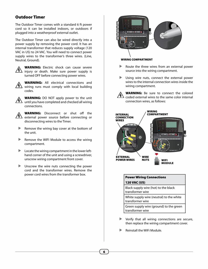
Outdoor Timer
The Outdoor Timer comes with a standard 6 ft power cord so it can be installed indoors, or outdoors if plugged into a weatherproof external outlet.
The Outdoor Timer can also be wired directly into a power supply by removing the power cord. It has an internal transformer that reduces supply voltage (120 VAC in US) to 24 VAC. You will need to connect power supply wires to the transformer’s three wires. (Line, Neutral, Ground).
WARNING: Electric shock can cause severe injury or death. Make sure power supply is turned OFF before connecting power wires.
WARNING: All electrical connections and wiring runs must comply with local building codes.
WARNING: DO NOT apply power to the unit until you have completed and checked all wiring connections.
WARNING: Disconnect or shut o� the external power source before connecting or disconnecting wires to the Timer.
Remove the wiring bay cover at the bottom of the unit.
Remove the WIFI Module to access the wiring compartment.
Locate the wiring compartment in the lower left-hand corner of the unit and using a screwdriver, unscrew wiring compartment front cover.
Unscrew the wire nuts connecting the power cord and the transformer wires. Remove the power cord wires from the transformer box.
CONNECT
120 VAC
CONNECT
WIRING COMPARTMENT
Route the three wires from an external power source into the wiring compartment.
Using wire nuts, connect the external power wires to the internal connection wires inside the wiring compartment.
WARNING: Be sure to connect the colored coded external wires to the same color internal connection wires, as follows:
Power Wiring Connections120 VAC (US)Black supply wire (hot) to the black transformer wire
White supply wire (neutral) to the white transformer wire
Green supply wire (ground) to the green transformer wire
Verify that all wiring connections are secure, then replace the wiring compartment cover.
Reinstall the WiFi Module.
INTERNAL CONNECTION WIRES
WIRING COMPARTMENT
EXTERNAL POWER WIRES
WIRE NUTS WIFI
MODULE
7
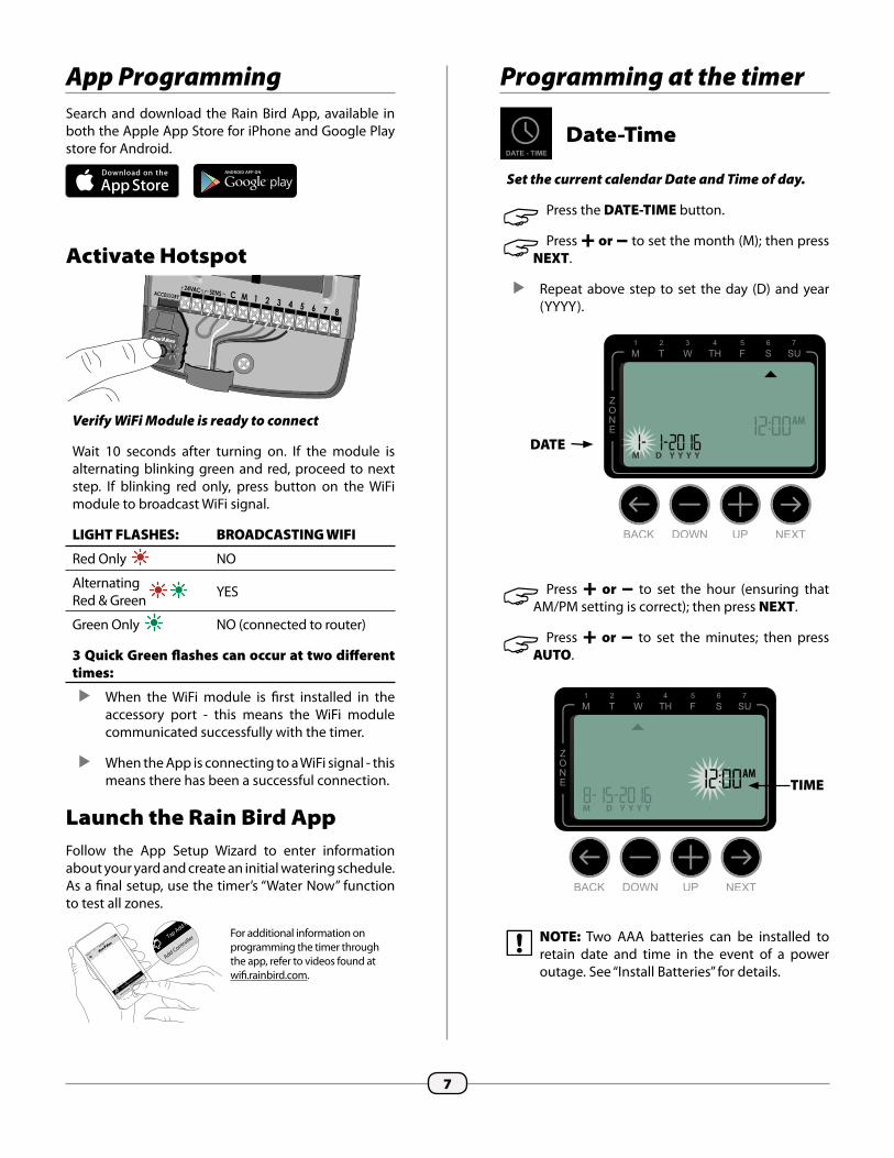
App ProgrammingSearch and download the Rain Bird App, available in both the Apple App Store for iPhone and Google Play store for Android.
Activate Hotspot
Verify WiFi Module is ready to connect
Wait 10 seconds after turning on. If the module is alternating blinking green and red, proceed to next step. If blinking red only, press button on the WiFi module to broadcast WiFi signal.
LIGHT FLASHES: BROADCASTING WIFI
Red Only NO
Alternating Red & Green YES
Green Only NO (connected to router)
3 Quick Green �ashes can occur at two di�erent times:
When the WiFi module is �rst installed in the accessory port - this means the WiFi module communicated successfully with the timer.
When the App is connecting to a WiFi signal - this means there has been a successful connection.
Launch the Rain Bird AppFollow the App Setup Wizard to enter information about your yard and create an initial watering schedule. As a �nal setup, use the timer’s “Water Now” function to test all zones.
Programming at the timer
Date-Time
Set the current calendar Date and Time of day.
"" Press the DATE-TIME button.
"" Press + or – to set the month (M); then press NEXT.
Repeat above step to set the day (D) and year (YYYY).
"" Press + or – to set the hour (ensuring that AM/PM setting is correct); then press NEXT.
"" Press + or – to set the minutes; then press AUTO.
NOTE: Two AAA batteries can be installed to retain date and time in the event of a power outage. See “Install Batteries” for details.
M D Y Y Y Y
AM
M D Y Y Y Y
AMTIME
DATE
100%
4:21 PM
Help/Support
Add ControllerTap Add Contro
ller to begin
Help/Support
Add ControllerTap Add Contro
ller to begin
For additional information on programming the timer through the app, refer to videos found at wi�.rainbird.com.

8
Watering Schedule
Create customized irrigation schedules to run automatically at speci�c times, durations and intervals.
These schedules will stay in sync with the schedules created in the app. If changes are made in the timer, they will be updated to the app the next time it is opened. Once changes are made in the app and saved, they will be shown at the timer screen.
"" Press the SCHEDULE button.
Select Zone
Zones are designated areas (for example, “Rose Garden”) that you de�ne as locations for watering.
"" Press + or – to select the desired Zone Number; then press NEXT.
Set Watering Run Times
Watering Run Times are durations (for example, 20 minutes) set for watering.
NOTE: Run Times can be set between 1 to 199 minutes.
"" Press + or – to set the desired Run Time (MIN); then press NEXT.
Set Watering Start Times
Watering Start Times are times of day at which watering is set to begin.
NOTE: A total of up to six Start Times (1-6) are available for each Zone.
"" Press + or – to set the 1st Start Time (ensuring that AM/PM setting is correct); then press NEXT.
NOTE: Start Time adjustments are set in 10 minute increments.
REPEAT as desired to set additional Start Times for that Zone.
NOTE: Pressing NEXT when -:- (OFF) is blinking on the display will advance to Step 4.
NOTE: If multiple zones have the same or over-lapping watering times, the Timer will water the zones in sequence (multiple zones will not run at the same time).
Set Watering Start Days
Watering Start Days are the calendar days or intervals (for example, Monday, Wednesday and Friday) on which watering is allowed.
"" Press + or – to select one of four available Watering Start Day options:
a. Custom Days - To schedule watering to occur on selected days of the week, go to 4a.
b. Odd Days - To schedule watering to occur on all odd calendar days (1,3,5...29 etc.), go to 4b.
c. Even Days - To schedule watering to occur on all even calendar days (2,4,6...30 etc.), go to 4c.
d. Cyclic Days - To schedule watering to occur at intervals (every 2 days, or 3 days, etc.), go to 4d.
1
2
MIN
RUN TIME
1
2
MIN
ZONE
1
2
MIN
START TIME

9
4a Custom Days
"" Press + or – to select then press NEXT.
"" Press + (to enable) or – (to disable) the blinking Selection Day. Cursor will then advance to the next Selection Day.
"" Press + or – to set each subsequent day of the week as desired.
REPEAT Steps 1-4 for remaining zones.
4b Odd Days
"" Press + or – to select then press NEXT.
REPEAT Steps 1-4 for remaining zones.
4c Even Days
"" Press + or – to select then press NEXT.
REPEAT Steps 1-4 for remaining zones.
SELECTION DAY

10
Options and Special Features
Rain DelayWatering schedules can be delayed manually for up to 14 days due to rain or other needs. While rain delay is enabled no scheduled watering will take place for any zones. The WATER NOW feature can still be used. After the immediate watering is complete from a WATER NOW session the rain delay feature will resume for the programmed number of days.
"" During normal operation, AUTO has been pressed,
Press and hold the + button.
The number 01 will appear on the screen along with the stop icon.
This means the rain delay has been enabled for 1 day.
"" To increase or decrease the rain delay press + or –.
To turn o� the rain delay press – until the days of rain delay turns to 0.
After the rain delay days are completed the watering schedule will resume.
Copy Zone to ZoneScheduling information can be copied from one zone to another zone to speed up programming.
"" Press the SCHEDULE button.
"" Press + or – to select the SUBSEQUENT Zone number.
"" Press and hold BACK, then press and release the SCHEDULE button.
4d Cyclic Days
"" Press + or – to select Cyclic Days; then press NEXT.
NOTE: If any settings for Day Cycle or Start Date have already been entered for previous zones, those values will be shown on the display.
"" Press + or – to set the desired Day Cycle; then press NEXT.
"" Press + or – to set desired Start Date; then press NEXT.
NOTE: The Start Date should be the �rst day the zone is to be watered. Only Start Dates that fall within the selected Day Cycle are available.
REPEAT Steps 1-4 for remaining zones.
DAY CYCLE
START DATE

11
NOTE: The next Zone will start watering immediately if Start Times are stacked.Otherwise, the next Zone will start according to the programmed schedule.
O�
Cancel all active watering immediately and disable automatic irrigation.
"" Press the OFF button to immediately cancel all active watering.
Programmed irrigation schedules remain stored in memory even when the Timer is turned o� or if power is lost.
NOTE: Press the AUTO button to resume normal operation. Automatic irrigation will NOT occur if the Timer remains in OFF mode.
Normal Operation
Auto
Watering occurs automatically according to programmed irrigation schedules.
"" Press the AUTO button to resume normal operation whenever programming is completed and to monitor active watering.
NOTE: Unless the OFF button is pressed, the Timer will revert to AUTO mode after 10 minutes if no programming activity (button presses) occurs during that time.
In Auto Mode:
The display shows the current time, date and day of the week:
During Watering:
The display shows a blinking sprinkler symbol, the active Zone number and watering Run Time remaining for that Zone.
"" Press + or – to adjust watering Run Time remaining for the active Zone as desired.
"" Press NEXT to cancel watering for the active Zone and advance to the next Zone in the irrigation cycle.
MIN
ZONE
RUN TIME

12
Water ONE Zone:
"" Press the MANUAL WATERING button.
"" Press + or – to select any ONE Zone; then press NEXT.
"" Press + or – to set the desired Run Time; then press NEXT to begin watering.
During Manual Watering:
"" Press + or – to adjust watering Run Time remaining for the active Zone as desired (reducing to 0 minutes will stop Manual Watering).
"" Press NEXT or OFF to stop the remaining Manual Watering cycle (if OFF is pressed, then press AUTO to resume normal operation).
Additional Features
Water Now
Start watering immediately for ALL Zones or for any ONE Zone.
Water ALL Zones:
"" Press the MANUAL WATERING button.
"" If timer has already been programmed, ALL Zones appears as the default selection; press NEXT to continue.
"" Press + or – to set the desired Run Time; then press NEXT to begin watering.
During Manual Watering:
"" Press + or – to adjust watering Run Time remaining for the active Zone as desired.
"" Press NEXT to cancel watering for the active Zone and advance to the next Zone in the cycle.
"" Press OFF to stop the remaining Manual Watering cycle; then press AUTO to resume normal operation.
MIN
MIN
ZONES
RUN TIME
MIN
MIN
ZONE
RUN TIME

13
Seasonal Adjust
Increase or decrease watering duration (Run Times) for all Zones.
"" Press the SEASONAL ADJUST button.
"" Press + or – to increase or decrease the SEASONAL ADJUST percentage setting.
NOTE: The SEASONAL ADJUST value can be adjusted from -90% to +100%. For example, a +50% adjustment means a Run Time of 10 minutes will become 15 minutes.
NOTE: If “Use Weather Correction Data” is enabled in the app, then adjusting the seasonal adjust at the timer will only make a change for the day. The adjustment will change back to the seasonal adjust setting controlled by the app the next day.
NOTE: SEASONAL ADJUST applies to ALL programmed irrigation schedules.
"" Press AUTO to resume normal operation.
SETTING

14
Troubleshooting
Error DetectionThe Timer has a built-in error detection that senses an electrical short circuit or overload condition on a Zone’s output line.
In the event of an error condition, the following steps take place regarding the error:
• The a�ected Zone number and “Err” alert message will show on the display when the unit is in either AUTO or MANUAL WATERING mode.
• All irrigation for the a�ected Zone is cancelled and watering advances to the next operable Zone in the irrigation queue.
Electrical Issues
Problem Possible Cause Possible SolutionDisplay shows error message “Err M.” Timer will not activate zones.
Problem with wiring to Master Valve (if used). There may be a break in the wire or a loose connection.
Check wiring and connections to master valve. Repair or replace wiring and valve if needed. To clear the �ashing error message, press NEXT.
Display is blank. Power not reaching the Timer. Verify the main AC power supply is securely plugged in or connected and working properly.
Verify the power supply wires are connected to the Timer “24 VAC” terminals. (Indoor model.)
Display is frozen and Timer will not accept programming.
An electrical surge may have interfered with the Timer’s electronics.
Unplug the Timer for 2 minutes, then plug it back in. If there is no permanent damage, the Timer should accept programming and resume normal operation.
Press and release the RESET button.
NOTE: The Timer will attempt to water the a�ected Zone again at the next scheduled watering. Completion of a successful watering will clear the error condition associated with that Zone.
M D Y Y Y Y

15
Connection Issues
Problem Possible Cause Possible SolutionConnection issues between mobile device and timer.
WiFi signal strength is low. Verify with your phone the WiFi signal is at least 2 bars of strength at the location of the timer. If it is not try to relocate the WiFi router so it is closer and does not have as much interference. If this is not possible, use a WiFi range extender to boost the signal strength.
Timer is not connected to mobile device and WiFi module is blinking green.
The mobile device needs to be re-connected to the controller, or connected for the �rst time. Follow App Programming instructions on page 7.
Timer is not connected to mobile device and WiFi module is blinking alternating red and green.
Verify the mobile device is connected to the Rain Bird WiFi signal. This can be done in the WiFi settings of the mobile device. Once the WiFi signal is connected, the app should be able to communicate with the timer.
Timer is not connected to mobile device and WiFi module is blinking red.
Press the WiFi module button and wait for the LED to start blinking alternating red and green. Launch the setup wizard by pressing the Add Controller button in the app and follow the easy step by step instructions. If there is a timer card in the app that is no longer being used it can be deleted by pressing the trash can button at the bottom of the card.
Timer is not connected to mobile device and WiFi module is not blinking.
Check to make sure the timer is plugged into an outlet, and the outlet is providing power. If the timer is powered, make sure the WiFi module is seated correctly in the accessory port. If needed, pull it out and plug it back in.
Watering Issues
Problem Possible Cause Possible SolutionProgrammed schedules and manual watering functions do not start.
Water source not supplying water. Verify there is no disruption to the main water line and that all other water supply lines are open and functioning properly.
Wiring is loose or not properly connected.
Check that valve wiring and master valve or pump start relay wiring is securely connected at the Timer and in the �eld.
Valve wires are corroded or damaged.
Check valve wiring for damage and replace if necessary. Check wiring connections and replace with watertight splice connectors if needed.
Connected rain sensor may be activated.
Let the rain sensor dry out or else disconnect it from the Timer terminal block and replace it with a jumper wire connecting the two SENS terminals.
Jumper wire connecting the two SENS terminals on the terminal block may be missing or damaged.
Jumper the two SENS terminals on the Timer terminal block by connecting them with a short length of 14 to 18 gauge wire.

®Registered trademark of the Rain Bird Corporation©2016 Rain Bird Corporation
182188-01 Rev.07/16
Rain Bird Corporation6991 East Southpoint Road Tucson, AZ 85756 Phone: (520) 741-6100 Fax: (520) 741-6522
www.rainbird.com
To comply with FCC and Industry Canada RF exposure limits for general population / uncontrolled exposure, the antenna(s) used for this transmitter must be installed to provide a separation distance of at least 35mm from all persons and operating in conjunction with any other antenna or transmitter.
This device complies with Part 15 of the FCC Rules and Industry Canada License-exempt RSS standards. Operation is subject to the following two conditions:
1. This device may not cause harmful interference, and
2. This device must accept any interference received, including interference that may cause undesired operation.
Changes or modifications not expressly approved by the party responsible for compliance could void the user’s authority to operate the equipment.
Recommended