Odyssey Cooling Condensing Units
R-22 Dry Charge7½ - 20 Ton, 60 Hz
SS-PRC037-ENJuly 2012
Product Catalog
R-22 Dry Charge, 7½ - 20 Ton
General Data
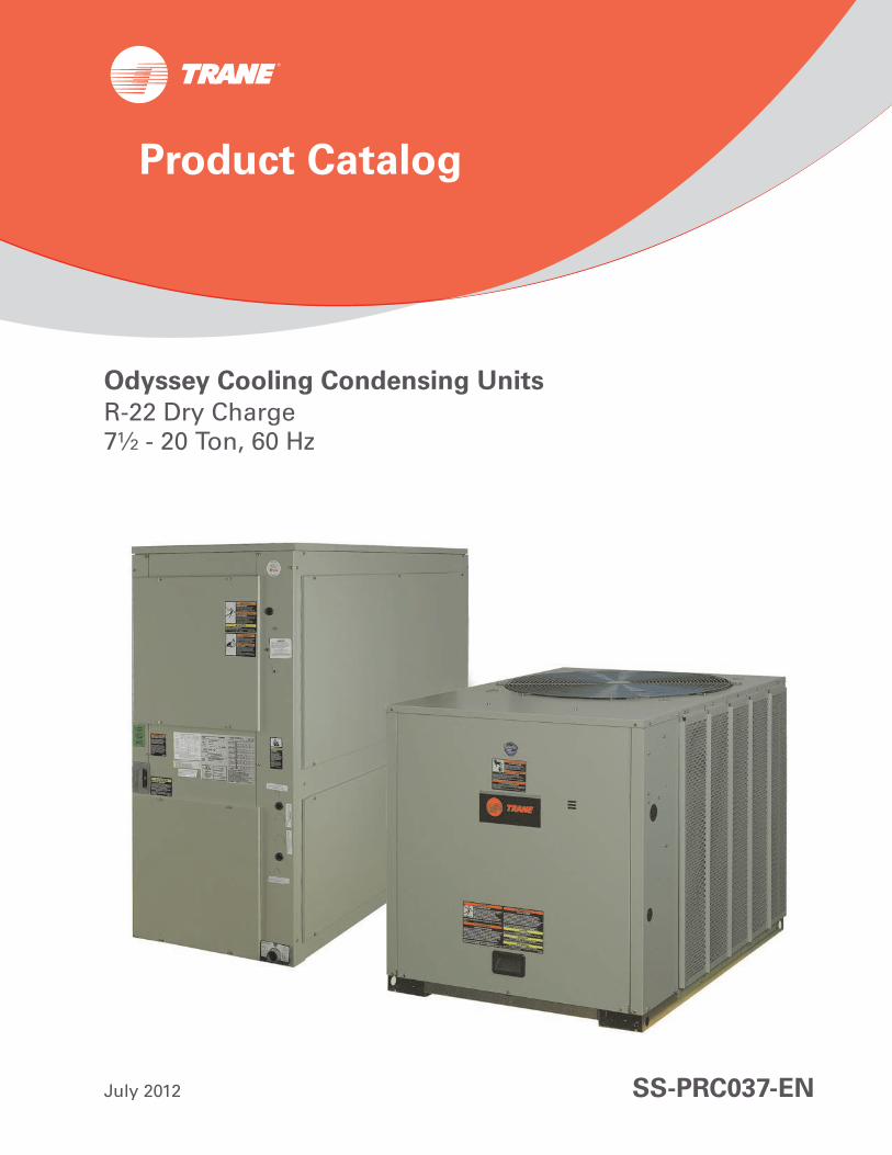
Table 1. General Data — 7½ - 20 Ton
7½ 10 15 20
Single Compressor TTA090A3, A4,
Single Compressor TTA120A3, A4,
Dual Compressor TTA180B3, B4,
Dual Compressor TTA240B3, B4,
Compressor
Type Scroll Scroll Scroll Scroll
No./Tons 1/6.9 1/8.6 2/6.9 2/8.6
System Data
No. Refrigerant Circuits 1 1 2 2
Suction Line (in.) OD 1 3/8 1 3/8 1 3/8 1 3/8
Liquid Line (in.) OD 5/8 1/2 1/2 1/2
Outdoor Coil - Type Lanced Lanced Lanced Lanced
Tube Size (in.) OD 0.375 0.375 0.375 0.375
Face Area (sq ft) 19.2 24.0 24.0 24.0
Rows/FPI 2/18 2/18 2/18 2/18
Outdoor Fan - Type Propeller Propeller Propeller Propeller
No. Used/Diameter (in.) 1/26 1/28 2/28 2/28
Drive Type/No. Speeds Direct/1 Direct/1 Direct/1 Direct/1
CFM 6530 9600 19500 19500
No. Motor/HP 1/0.5 1/1 2/1 2/1
Motor RPM 1100 1100 1100 1100
Refrigerant Charge (Field Supplied) R-22 17.6 22.5 39.0 43.8
Shipping Dimensions (HxWxD) 43.54” x 43” x 36.5” 43.49” x 53” x 40.5” 49.48" x 94.75" x 47" 49.48" x 94.75" x 47"
2 SS-PRC037-EN
R-22 Dry Charge, 7½ - 20 Ton
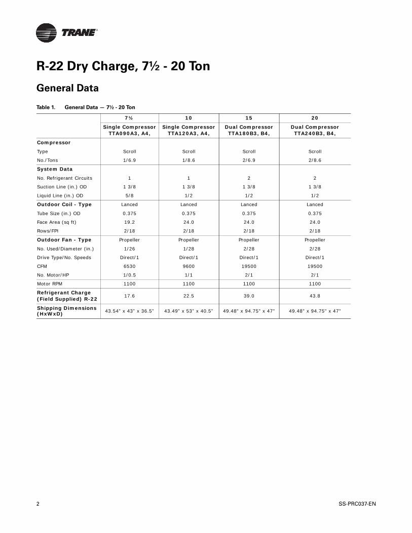
Accessories
Model Description Used With
Coil Guard
BAYGARD058A
Hail/Vandal Guard
TTA090A
BAYGARD059A TTA120A
BAYGARD061A TTA180B, TTA240B
Isolators
BAYISLT004A Rubber Isolator Floor (blue) TTA090A
BAYISLT005A Rubber Isolator Floor (black) TTA120A
BAYISTL009A Rubber Isolator Floor (red) TTA180B
BAYISTL010A Rubber Isolator Floor (green) TTA240B
BAYISLT023A Steel Spring Isolator Floor (red) TTA090A, TTA120A
BAYISLT024A Steel Spring Isolator Floor (black) TTA180B
BAYISLT025A Steel Spring Isolator Floor (yellow) TTA240B
Low Ambient
BAYLOAMU01B(a)(b)(c)
(a) Kit mounts external to the outdoor unit and operates by sensing ambient and liquid line temperatures.(b) Cycles fan on/off, (no modulating).(c) Reliatel requires onboard EDC function to be disabled when BAYLOAM is used, remove OA sensor from terminal J8-1&2
On/Off Fan Control Mounted in External Enclosure (small cabinets) TTA090A (all voltages)
BAYLOAMU02B(b)(c) On/Off Fan Control Mounted in Unit Control Box (large cabinets) TTA120A-TTA240B (all voltages)
SS-PRC037-EN 3
R-22 Dry Charge, 7½ - 20 Ton
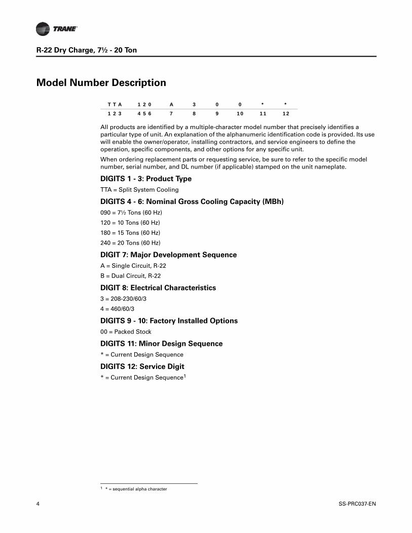
Model Number Description
All products are identified by a multiple-character model number that precisely identifies a particular type of unit. An explanation of the alphanumeric identification code is provided. Its use will enable the owner/operator, installing contractors, and service engineers to define the operation, specific components, and other options for any specific unit.
When ordering replacement parts or requesting service, be sure to refer to the specific model number, serial number, and DL number (if applicable) stamped on the unit nameplate.
DIGITS 1 - 3: Product Type
TTA = Split System Cooling
DIGITS 4 - 6: Nominal Gross Cooling Capacity (MBh)
090 = 7½ Tons (60 Hz)
120 = 10 Tons (60 Hz)
180 = 15 Tons (60 Hz)
240 = 20 Tons (60 Hz)
DIGIT 7: Major Development Sequence
A = Single Circuit, R-22
B = Dual Circuit, R-22
DIGIT 8: Electrical Characteristics
3 = 208-230/60/3
4 = 460/60/3
DIGITS 9 - 10: Factory Installed Options
00 = Packed Stock
DIGITS 11: Minor Design Sequence
* = Current Design Sequence
DIGITS 12: Service Digit
* = Current Design Sequence1
T T A 1 2 0 A 3 0 0 * *
1 2 3 4 5 6 7 8 9 10 11 12
1 * = sequential alpha character
4 SS-PRC037-EN
R-22 Dry Charge, 7½ - 20 Ton
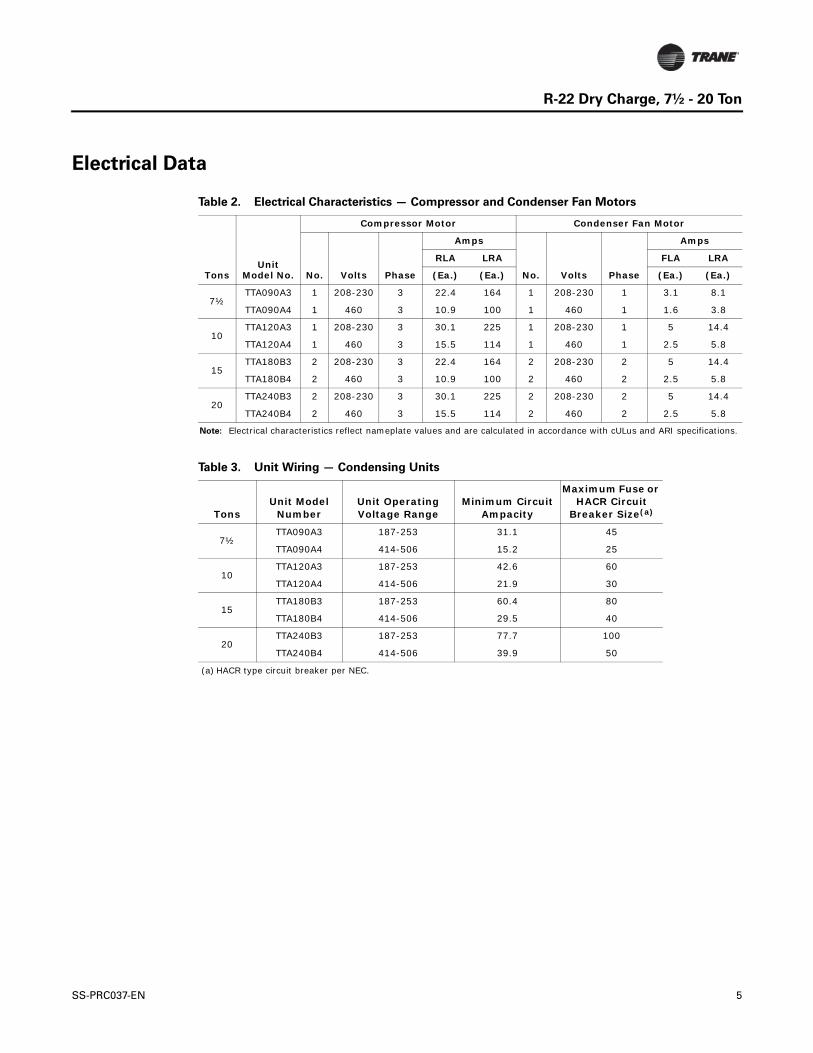
Electrical Data
Table 2. Electrical Characteristics — Compressor and Condenser Fan Motors
TonsUnit
Model No.
Compressor Motor Condenser Fan Motor
No. Volts Phase
Amps
No. Volts Phase
Amps
RLA LRA FLA LRA
(Ea.) (Ea.) (Ea.) (Ea.)
7½TTA090A3 1 208-230 3 22.4 164 1 208-230 1 3.1 8.1
TTA090A4 1 460 3 10.9 100 1 460 1 1.6 3.8
10TTA120A3 1 208-230 3 30.1 225 1 208-230 1 5 14.4
TTA120A4 1 460 3 15.5 114 1 460 1 2.5 5.8
15TTA180B3 2 208-230 3 22.4 164 2 208-230 2 5 14.4
TTA180B4 2 460 3 10.9 100 2 460 2 2.5 5.8
20TTA240B3 2 208-230 3 30.1 225 2 208-230 2 5 14.4
TTA240B4 2 460 3 15.5 114 2 460 2 2.5 5.8
Note: Electrical characteristics reflect nameplate values and are calculated in accordance with cULus and ARI specifications.
Table 3. Unit Wiring — Condensing Units
TonsUnit Model
NumberUnit Operating Voltage Range
Minimum Circuit Ampacity
Maximum Fuse or HACR Circuit
Breaker Size(a)
(a) HACR type circuit breaker per NEC.
7½TTA090A3 187-253 31.1 45
TTA090A4 414-506 15.2 25
10TTA120A3 187-253 42.6 60
TTA120A4 414-506 21.9 30
15TTA180B3 187-253 60.4 80
TTA180B4 414-506 29.5 40
20TTA240B3 187-253 77.7 100
TTA240B4 414-506 39.9 50
SS-PRC037-EN 5
R-22 Dry Charge, 7½ - 20 Ton
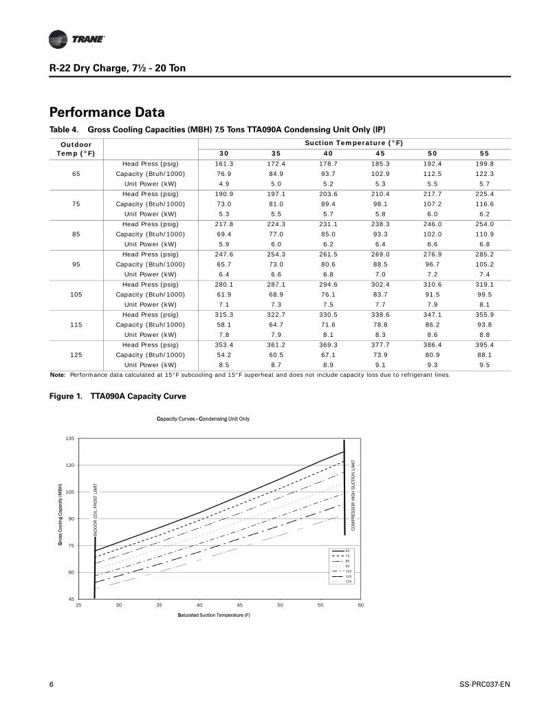
Performance DataTable 4. Gross Cooling Capacities (MBH) 7.5 Tons TTA090A Condensing Unit Only (IP)
Outdoor Temp (°F)
Suction Temperature (°F)30 35 40 45 50 55
65Head Press (psig) 161.3 172.4 178.7 185.3 192.4 199.8
Capacity (Btuh/1000) 76.9 84.9 93.7 102.9 112.5 122.3Unit Power (kW) 4.9 5.0 5.2 5.3 5.5 5.7
75Head Press (psig) 190.9 197.1 203.6 210.4 217.7 225.4
Capacity (Btuh/1000) 73.0 81.0 89.4 98.1 107.2 116.6Unit Power (kW) 5.3 5.5 5.7 5.8 6.0 6.2
85Head Press (psig) 217.8 224.3 231.1 238.3 246.0 254.0
Capacity (Btuh/1000) 69.4 77.0 85.0 93.3 102.0 110.9Unit Power (kW) 5.9 6.0 6.2 6.4 6.6 6.8
95Head Press (psig) 247.6 254.3 261.5 269.0 276.9 285.2
Capacity (Btuh/1000) 65.7 73.0 80.6 88.5 96.7 105.2Unit Power (kW) 6.4 6.6 6.8 7.0 7.2 7.4
105Head Press (psig) 280.1 287.1 294.6 302.4 310.6 319.1
Capacity (Btuh/1000) 61.9 68.9 76.1 83.7 91.5 99.5Unit Power (kW) 7.1 7.3 7.5 7.7 7.9 8.1
115Head Press (psig) 315.3 322.7 330.5 338.6 347.1 355.9
Capacity (Btuh/1000) 58.1 64.7 71.6 78.8 86.2 93.8Unit Power (kW) 7.8 7.9 8.1 8.3 8.6 8.8
125Head Press (psig) 353.4 361.2 369.3 377.7 386.4 395.4
Capacity (Btuh/1000) 54.2 60.5 67.1 73.9 80.9 88.1Unit Power (kW) 8.5 8.7 8.9 9.1 9.3 9.5
Note: Performance data calculated at 15°F subcooling and 15°F superheat and does not include capacity loss due to refrigerant lines.
Figure 1. TTA090A Capacity Curve
45
60
75
90
105
120
135
25 30 35 40 45 50 55 60
GGro
ss C
oolin
g C
apac
ity (M
BH
)
SSaturated Suction Temperature (F)
CCapacity Curves -- CCondensing Unit Only
65
75
85
95
105
115
125
IND
OO
R C
OIL
FR
OST
LIM
IT
COM
PRES
SOR
HIG
H S
UCT
ION
LIM
IT
6 SS-PRC037-EN
R-22 Dry Charge, 7½ - 20 Ton
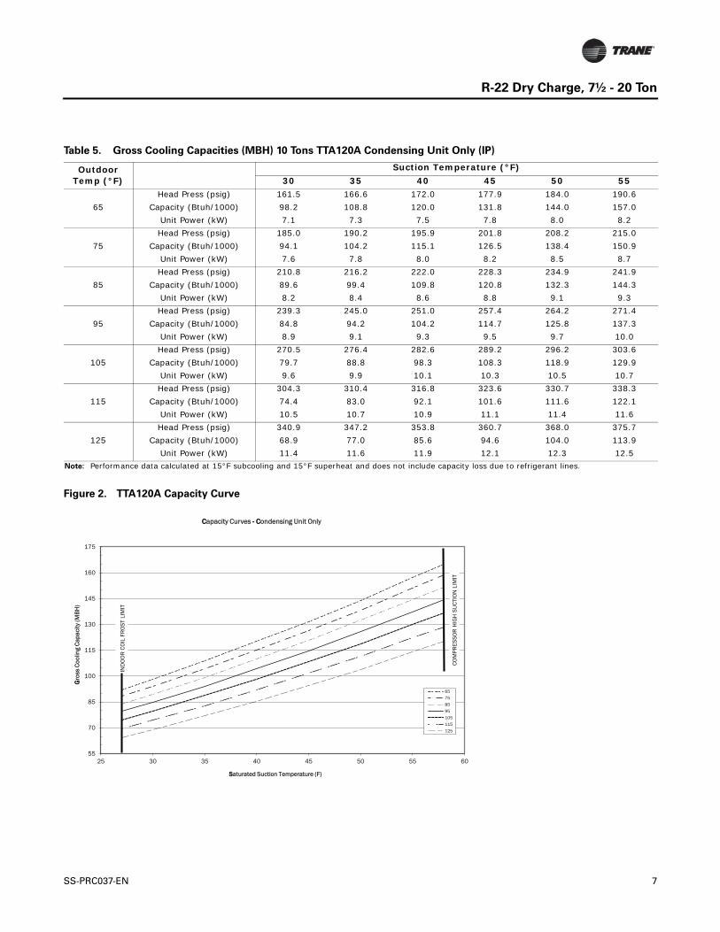
Table 5. Gross Cooling Capacities (MBH) 10 Tons TTA120A Condensing Unit Only (IP)
Outdoor Temp (°F)
Suction Temperature (°F)30 35 40 45 50 55
65Head Press (psig) 161.5 166.6 172.0 177.9 184.0 190.6
Capacity (Btuh/1000) 98.2 108.8 120.0 131.8 144.0 157.0Unit Power (kW) 7.1 7.3 7.5 7.8 8.0 8.2
75Head Press (psig) 185.0 190.2 195.9 201.8 208.2 215.0
Capacity (Btuh/1000) 94.1 104.2 115.1 126.5 138.4 150.9Unit Power (kW) 7.6 7.8 8.0 8.2 8.5 8.7
85Head Press (psig) 210.8 216.2 222.0 228.3 234.9 241.9
Capacity (Btuh/1000) 89.6 99.4 109.8 120.8 132.3 144.3Unit Power (kW) 8.2 8.4 8.6 8.8 9.1 9.3
95Head Press (psig) 239.3 245.0 251.0 257.4 264.2 271.4
Capacity (Btuh/1000) 84.8 94.2 104.2 114.7 125.8 137.3Unit Power (kW) 8.9 9.1 9.3 9.5 9.7 10.0
105Head Press (psig) 270.5 276.4 282.6 289.2 296.2 303.6
Capacity (Btuh/1000) 79.7 88.8 98.3 108.3 118.9 129.9Unit Power (kW) 9.6 9.9 10.1 10.3 10.5 10.7
115Head Press (psig) 304.3 310.4 316.8 323.6 330.7 338.3
Capacity (Btuh/1000) 74.4 83.0 92.1 101.6 111.6 122.1Unit Power (kW) 10.5 10.7 10.9 11.1 11.4 11.6
125Head Press (psig) 340.9 347.2 353.8 360.7 368.0 375.7
Capacity (Btuh/1000) 68.9 77.0 85.6 94.6 104.0 113.9Unit Power (kW) 11.4 11.6 11.9 12.1 12.3 12.5
Note: Performance data calculated at 15°F subcooling and 15°F superheat and does not include capacity loss due to refrigerant lines.
Figure 2. TTA120A Capacity Curve
55
70
85
100
115
130
145
160
175
25 30 35 40 45 50 55 60
GGro
ss C
oolin
g C
apac
ity (M
BH
)
SSaturated Suction Temperature (F)
CCapacity Curves -- CCondensing Unit Only
65
75
85
95
105
115
125
IND
OO
R C
OIL
FR
OST
LIM
IT
COM
PRES
SOR
HIG
H S
UCT
ION
LIM
IT
SS-PRC037-EN 7
R-22 Dry Charge, 7½ - 20 Ton
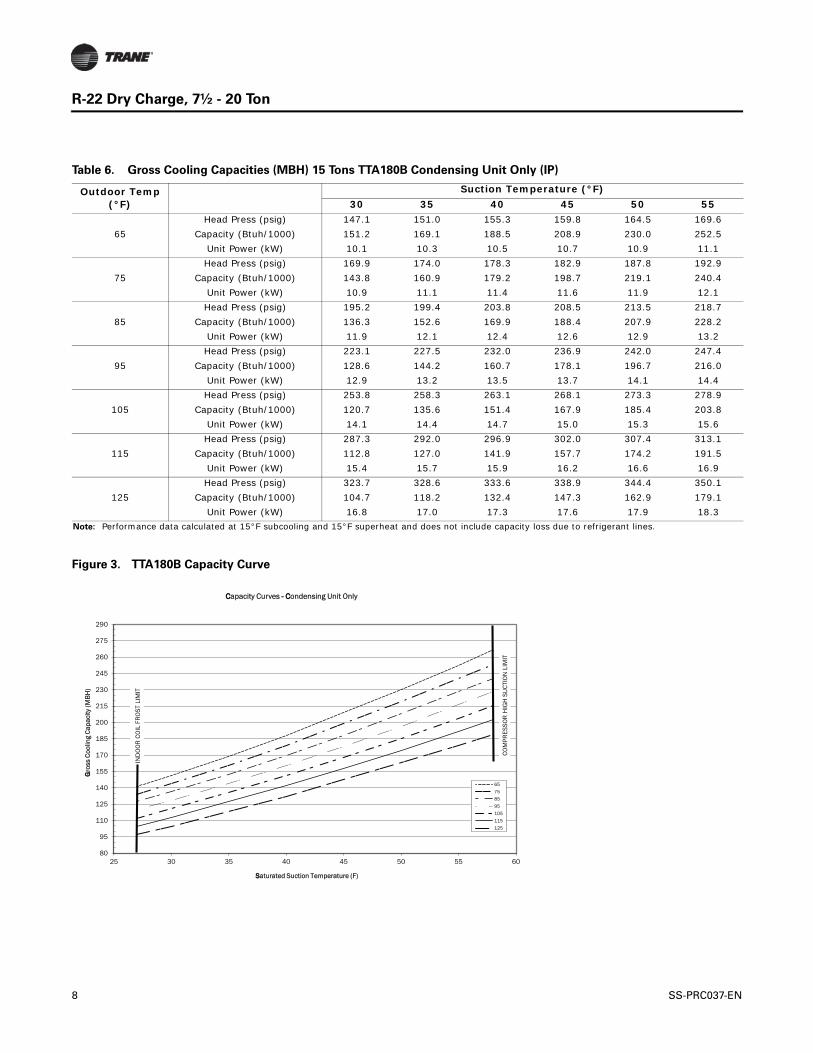
Table 6. Gross Cooling Capacities (MBH) 15 Tons TTA180B Condensing Unit Only (IP)
Outdoor Temp (°F)
Suction Temperature (°F)30 35 40 45 50 55
65Head Press (psig) 147.1 151.0 155.3 159.8 164.5 169.6
Capacity (Btuh/1000) 151.2 169.1 188.5 208.9 230.0 252.5Unit Power (kW) 10.1 10.3 10.5 10.7 10.9 11.1
75Head Press (psig) 169.9 174.0 178.3 182.9 187.8 192.9
Capacity (Btuh/1000) 143.8 160.9 179.2 198.7 219.1 240.4Unit Power (kW) 10.9 11.1 11.4 11.6 11.9 12.1
85Head Press (psig) 195.2 199.4 203.8 208.5 213.5 218.7
Capacity (Btuh/1000) 136.3 152.6 169.9 188.4 207.9 228.2Unit Power (kW) 11.9 12.1 12.4 12.6 12.9 13.2
95Head Press (psig) 223.1 227.5 232.0 236.9 242.0 247.4
Capacity (Btuh/1000) 128.6 144.2 160.7 178.1 196.7 216.0Unit Power (kW) 12.9 13.2 13.5 13.7 14.1 14.4
105Head Press (psig) 253.8 258.3 263.1 268.1 273.3 278.9
Capacity (Btuh/1000) 120.7 135.6 151.4 167.9 185.4 203.8Unit Power (kW) 14.1 14.4 14.7 15.0 15.3 15.6
115Head Press (psig) 287.3 292.0 296.9 302.0 307.4 313.1
Capacity (Btuh/1000) 112.8 127.0 141.9 157.7 174.2 191.5Unit Power (kW) 15.4 15.7 15.9 16.2 16.6 16.9
125Head Press (psig) 323.7 328.6 333.6 338.9 344.4 350.1
Capacity (Btuh/1000) 104.7 118.2 132.4 147.3 162.9 179.1Unit Power (kW) 16.8 17.0 17.3 17.6 17.9 18.3
Note: Performance data calculated at 15°F subcooling and 15°F superheat and does not include capacity loss due to refrigerant lines.
Figure 3. TTA180B Capacity Curve
80
95
110
125
140
155
170
185
200
215
230
245
260
275
290
25 30 35 40 45 50 55 60
GGro
ss C
oolin
g C
apac
ity (M
BH
)
SSaturated Suction Temperature (F)
CCapacity Curves -- CCondensing Unit Only
65
75
85
95
105
115
125
IND
OO
R C
OIL
FR
OST
LIM
IT
CO
MPR
ESSO
R H
IGH
SU
CTI
ON
LIM
IT
8 SS-PRC037-EN
R-22 Dry Charge, 7½ - 20 Ton
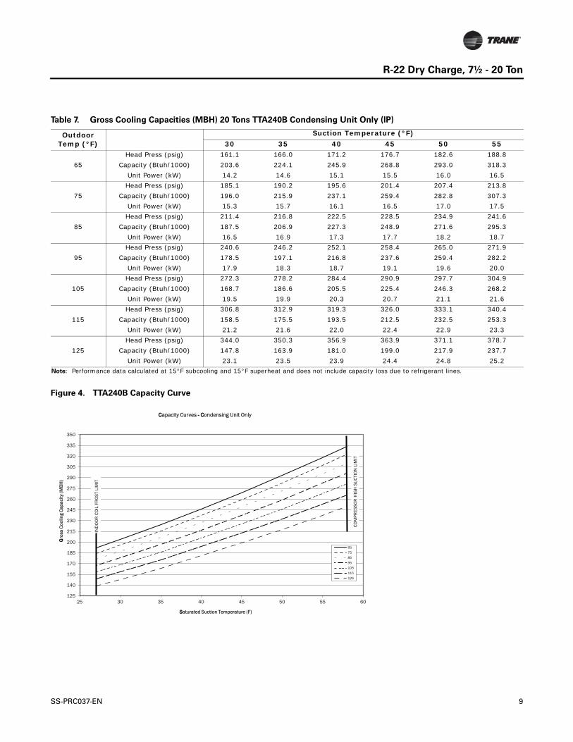
Table 7. Gross Cooling Capacities (MBH) 20 Tons TTA240B Condensing Unit Only (IP)
Outdoor Temp (°F)
Suction Temperature (°F)30 35 40 45 50 55
65Head Press (psig) 161.1 166.0 171.2 176.7 182.6 188.8
Capacity (Btuh/1000) 203.6 224.1 245.9 268.8 293.0 318.3Unit Power (kW) 14.2 14.6 15.1 15.5 16.0 16.5
75Head Press (psig) 185.1 190.2 195.6 201.4 207.4 213.8
Capacity (Btuh/1000) 196.0 215.9 237.1 259.4 282.8 307.3Unit Power (kW) 15.3 15.7 16.1 16.5 17.0 17.5
85Head Press (psig) 211.4 216.8 222.5 228.5 234.9 241.6
Capacity (Btuh/1000) 187.5 206.9 227.3 248.9 271.6 295.3Unit Power (kW) 16.5 16.9 17.3 17.7 18.2 18.7
95Head Press (psig) 240.6 246.2 252.1 258.4 265.0 271.9
Capacity (Btuh/1000) 178.5 197.1 216.8 237.6 259.4 282.2Unit Power (kW) 17.9 18.3 18.7 19.1 19.6 20.0
105Head Press (psig) 272.3 278.2 284.4 290.9 297.7 304.9
Capacity (Btuh/1000) 168.7 186.6 205.5 225.4 246.3 268.2Unit Power (kW) 19.5 19.9 20.3 20.7 21.1 21.6
115Head Press (psig) 306.8 312.9 319.3 326.0 333.1 340.4
Capacity (Btuh/1000) 158.5 175.5 193.5 212.5 232.5 253.3Unit Power (kW) 21.2 21.6 22.0 22.4 22.9 23.3
125Head Press (psig) 344.0 350.3 356.9 363.9 371.1 378.7
Capacity (Btuh/1000) 147.8 163.9 181.0 199.0 217.9 237.7Unit Power (kW) 23.1 23.5 23.9 24.4 24.8 25.2
Note: Performance data calculated at 15°F subcooling and 15°F superheat and does not include capacity loss due to refrigerant lines.
Figure 4. TTA240B Capacity Curve
125
140
155
170
185
200
215
230
245
260
275
290
305
320
335
350
25 30 35 40 45 50 55 60
GGro
ss C
oolin
g C
apac
ity (M
BH
)
SSaturated Suction Temperature (F)
CCapacity Curves -- CCondensing Unit Only
65
75
85
95
105
115
125
IND
OO
R C
OIL
FR
OST
LIM
IT
CO
MPR
ESSO
R H
IGH
SU
CTI
ON
LIM
IT
SS-PRC037-EN 9
R-22 Dry Charge, 7½ - 20 Ton
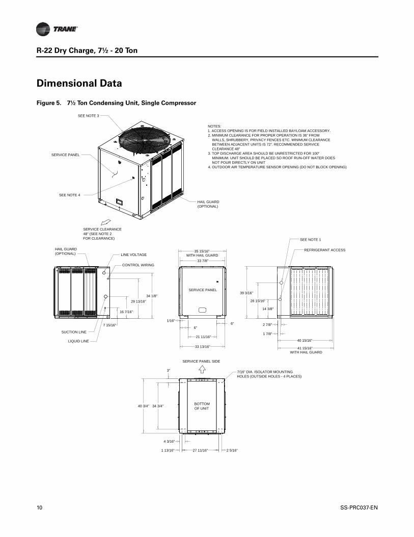
Dimensional Data
Figure 5. 7½ Ton Condensing Unit, Single Compressor
BOTTOMOF UNIT
7 15/16"
16 7/16"
29 13/16"34 1/8"
14 3/8"
26 15/16"
39 3/16"
2 7/8"
1 7/8"
33 13/16"
1/16"
6"
21 11/16"
6"
34 3/4"40 3/4"
3"
1 13/16" 27 11/16" 2 5/16"
4 3/16"
33 7/8"
35 15/16"
40 15/16"
41 15/16"
NOTES:1. ACCESS OPENING IS FOR FIELD INSTALLED BAYLOAM ACCESSORY.2. MINIMUM CLEARANCE FOR PROPER OPERATION IS 36" FROM WALLS, SHRUBBERY, PRIVACY FENCES ETC. MINIMUM CLEARANCE BETWEEN ADJACENT UNITS IS 72". RECOMMENDED SERVICE CLEARANCE 48"3. TOP DISCHARGE AREA SHOULD BE UNRESTRICTED FOR 100" MINIMUM. UNIT SHOULD BE PLACED SO ROOF RUN-OFF WATER DOES NOT POUR DIRECTLY ON UNIT4. OUTDOOR AIR TEMPERATURE SENSOR OPENING (DO NOT BLOCK OPENING)
SERVICE CLEARANCE 48" (SEE NOTE 2FOR CLEARANCE) SEE NOTE 1
REFRIGERANT ACCESS
HAIL GUARD (OPTIONAL)
SUCTION LINE
LIQUID LINE
CONTROL WIRING
LINE VOLTAGE
SERVICE PANEL
HAIL GUARD (OPTIONAL)
SERVICE PANEL
7/16" DIA. ISOLATOR MOUNTING HOLES (OUTSIDE HOLES - 4 PLACES)
SEE NOTE 3
SERVICE PANEL SIDE
SEE NOTE 4
WITH HAIL GUARD
WITH HAIL GUARD
10 SS-PRC037-EN
R-22 Dry Charge, 7½ - 20 Ton
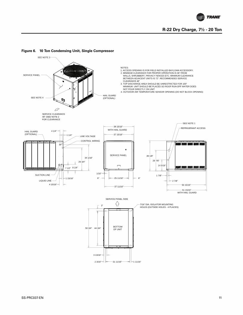
Figure 6. 10 Ton Condensing Unit, Single Compressor
BOTTOMOF UNIT
14 5/16"
26 7/8"
39 1/8"
2 7/8"
1 7/8"
34 1/16"
7 1/2" 8 1/4"
29 3/4"
4 15/16"
1 15/16"
4 1/4"
1 1/4"
37 11/16"
1/16"
6" 6"25 11/16"
37 15/16"
3"
50 3/4" 44 3/4"
1 11/16"31 11/16"
3 13/16"
2 3/16"
39 15/16"
50 15/16"
51 15/16"
LIQUID LINE
SUCTION LINE
SERVICE PANEL SIDE
SERVICE CLEARANCE 48" (SEE NOTE 2FOR CLEARANCE
HAIL GUARD (OPTIONAL)
SERVICE PANEL
SEE NOTE 3
HAIL GUARD (OPTIONAL)
SERVICE PANEL
CONTROL WIRING
LINE VOLTAGE
REFRIGERANT ACCESS
SEE NOTE 1
SEE NOTE 4
WITH HAIL GUARD
7/16" DIA. ISOLATOR MOUNTING HOLES (OUTSIDE HOLES - 4 PLACES)
NOTES:1. ACCESS OPENING IS FOR FIELD INSTALLED BAYLOAM ACCESSORY.2. MINIMUM CLEARANCE FOR PROPER OPERATION IS 36" FROM WALLS, SHRUBBERY, PRIVACY FENCES ETC. MINIMUM CLEARANCE BETWEEN ADJACENT UNITS IS 72". RECOMMENDED SERVICE CLEARANCE 48"3. TOP DISCHARGE AREA SHOULD BE UNRESTRICTED FOR 100" MINIMUM. UNIT SHOULD BE PLACED SO ROOF RUN-OFF WATER DOES NOT POUR DIRECTLY ON UNIT4. OUTDOOR AIR TEMPERATURE SENSOR OPENING (DO NOT BLOCK OPENING)
WITH HAIL GUARD
SS-PRC037-EN 11
R-22 Dry Charge, 7½ - 20 Ton
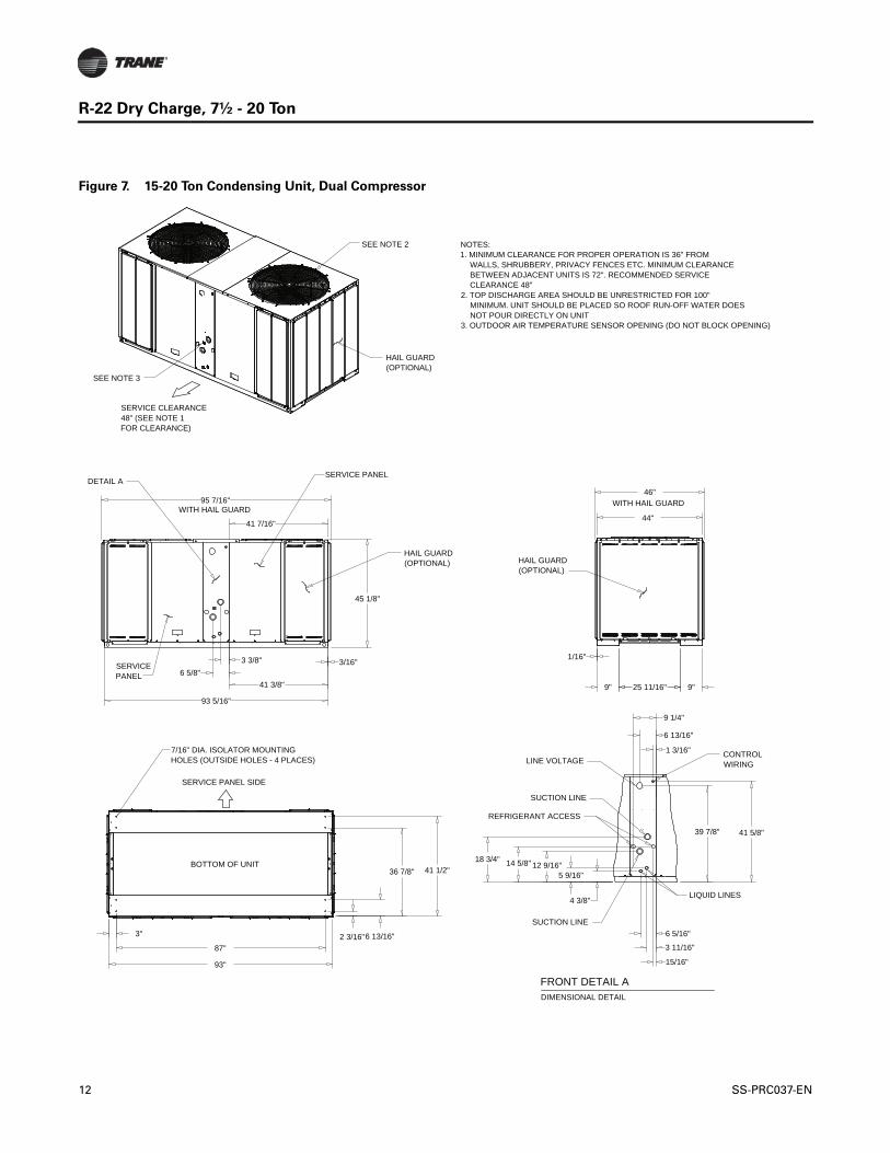
Figure 7. 15-20 Ton Condensing Unit, Dual Compressor
BOTTOM OF UNIT
1/16"
9" 9"25 11/16"
3/16"
45 1/8"
41 5/8"39 7/8"
4 3/8"
5 9/16"12 9/16"14 5/8"18 3/4"
6 13/16"
1 3/16"
15/16"
9 1/4"
3 3/8"6 5/8"
3 11/16"
6 5/16"
44"
93"
87"
41 1/2"
2 3/16"3" 6 13/16"
36 7/8"
41 3/8"
41 7/16"
93 5/16"
95 7/16"46"
LINE VOLTAGE
SUCTION LINE
REFRIGERANT ACCESS
LIQUID LINES
SUCTION LINE
NOTES:1. MINIMUM CLEARANCE FOR PROPER OPERATION IS 36" FROM WALLS, SHRUBBERY, PRIVACY FENCES ETC. MINIMUM CLEARANCE BETWEEN ADJACENT UNITS IS 72". RECOMMENDED SERVICE CLEARANCE 48"2. TOP DISCHARGE AREA SHOULD BE UNRESTRICTED FOR 100" MINIMUM. UNIT SHOULD BE PLACED SO ROOF RUN-OFF WATER DOES NOT POUR DIRECTLY ON UNIT3. OUTDOOR AIR TEMPERATURE SENSOR OPENING (DO NOT BLOCK OPENING)
7/16" DIA. ISOLATOR MOUNTING HOLES (OUTSIDE HOLES - 4 PLACES)
SERVICE PANEL SIDE
SERVICE CLEARANCE 48" (SEE NOTE 1FOR CLEARANCE)
HAIL GUARD (OPTIONAL)
HAIL GUARD (OPTIONAL)
SERVICEPANEL
DIMENSIONAL DETAIL
FRONT DETAIL A
SEE NOTE 2
HAIL GUARD (OPTIONAL)
DETAIL ASERVICE PANEL
CONTROLWIRING
WITH HAIL GUARDWITH HAIL GUARD
SEE NOTE 3
12 SS-PRC037-EN
R-22 Dry Charge, 7½ - 20 Ton
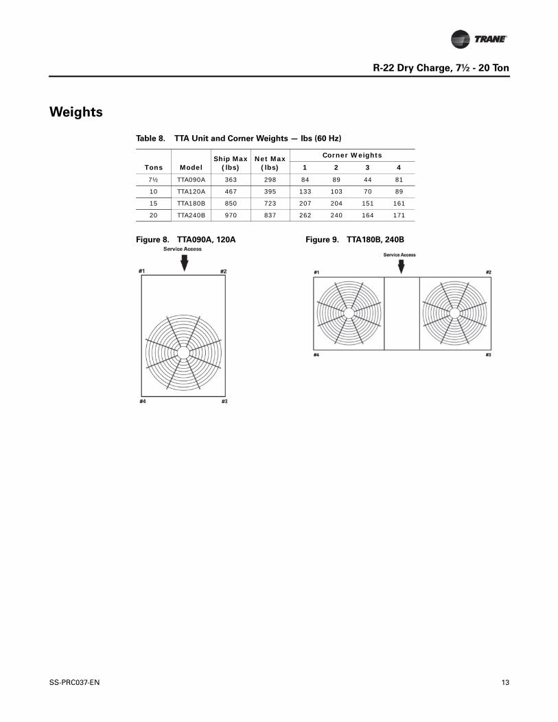
Weights
Table 8. TTA Unit and Corner Weights — lbs (60 Hz)
Tons ModelShip Max
(lbs)Net Max
(lbs)
Corner Weights
1 2 3 4
7½ TTA090A 363 298 84 89 44 81
10 TTA120A 467 395 133 103 70 89
15 TTA180B 850 723 207 204 151 161
20 TTA240B 970 837 262 240 164 171
Figure 8. TTA090A, 120A Figure 9. TTA180B, 240B
SS-PRC037-EN 13
Trane optimizes the performance of homes and buildings around the world. A business of Ingersoll Rand, theleader in creating and sustaining safe, comfortable and energy efficient environments, Trane offers a broadportfolio of advanced controls and HVAC systems, comprehensive building services, and parts. For moreinformation, visit www.Trane.com.
Trane has a policy of continuous product and product data improvement and reserves the right to change design and specifications without notice.
We are committed to using environmentally
conscious print practices that reduce waste.
© 2012 Trane All rights reserved
SS-PRC037-EN 30 Jul 2012
Supersedes SS-PRC037-EN (26 Jun 2012)
Recommended