Speed control of doubly star induction motor (DSIM) using direct field oriented control (DFOC)
based on fuzzy logic controller (FLC)
Lallouani Hellali*, Saad Belhamdi
Electrical Engineering Laboratory, University of Mohamed Boudiaf- Msila, Algeria
Corresponding Author Email: [email protected]
https://doi.org/10.18280/ama_c.730402
Received: 23 December 2017
Accepted: 15 March 2018
ABSTRACT
The aim for this paper is a proportional and integral (PI) controller and fuzzy logic (FLC)
controller devoted to improve the performance of Direct field orient control (DFOC)
strategy of doubly star induction motor (DSIM) fed by two inverters. In addition, the paper
describes a model of doubly star induction motor in d-q reference frame theory and its
computer simulation in MATLAB/SIMULINK®, fed by Pulse Width Modulation (PWM)
inverter to be studied. The performance of the Direct Field orientated control with a PI and
FLC is tested under different speed command and load disturbances. And also show a better
robustness beside the parametric variations of the motor.
Keywords:
doubly star induction motor, PMW, fuzzy
logic, direct field orient control, robustness
1. INTRODUCTION
Nowadays, many industry segments need doubly star
induction motors are one of widely used motor. Due to their
advantages in power segmentation, reliability, and minimized
torque pulsations. Such segmented structures are very
attractive for high-power applications since they allow the use
of lower rating power electronic devices at a switching
frequency higher than the one usually used in three-phase AC
machine drives. This machine has been used required in many
applications, such as pumps, fans, compressors, rolling mills,
cement mills, mine hoists [1].
In recent years, the multiphase machines, five-phase and
six-phase induction are the most considered in the literature.
The present study is focused on the doubly star Induction
motor. This type of machine is composed by two three-phase
windings shifted by 30 degrees and a standard simple squirrel-
cage rotor [2].
In order to ensure an effective control of DSIM, several
methods have been proposed [3]. An alternative solution is the
use of Direct Rotor-Field-Oriented Control (DFOC) is modern
technique for high-performance control of PWM inverter fed
DSIM. To achieve a variable speed operation a power
electronics inverter can be used. The Direct field oriented
control theory is the base of a special control method for
doubly star induction motor drives. With this theory doubly
star induction motors can be controlled like a separately
excited dc motor. This method enables the control of field and
torque of the DSIM independently (decoupling) by
manipulating the corresponding field oriented quantities [4-5,
11, 14].
In the aim to improve the performance of the electrical
drives based on traditional DFOC, fuzzy logic direct oriented
control attracts more and more the attention of many scientists
the configuration and design of the fuzzy Logic Controller for
the direct field oriented based control of DSIM. The proposed
fuzzy logic controller has been successfully simulated on a
simulink model with the help of fuzzy logic toolbox. The
performance of the FLC compared with the conventional PI
controller. The proposed FLC is insensitive to torque and
speed command variation changes and changes in parameter
variations.
This paper is structured as follows: In Section 2 the model
of the DSIM is presented, a suitable transformation matrix is
used to develop a simple dynamic model. We will describe the
Direct Field Oriented control by a fuzzy logic controller; the
designed direct field oriented models are introduced and
explained, In order to improve the static and dynamic control
performance of the DSIM in section 3. Section 4 shows
simulation results for a comparison between the performances
of FLC speed controller of direct field oriented control DSIM
with those obtained from conventional PI controller under
various conditions operation (resistant torque, reference speed
and parameter variations). The section 5 concludes this paper.
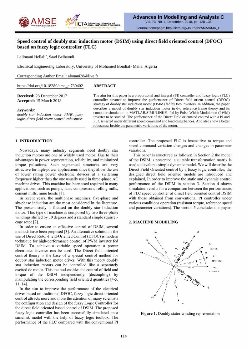
2. MACHINE MODELING
Figure 1. Doubly stator winding representation
Advances in Modelling and Analysis C Vol. 73, No. 4, December, 2018, pp. 128-136
Journal homepage: http://iieta.org/Journals/AMA/AMA_C
128
The doubly stator induction machine represented by two
stators windings: As1, Bs1, Cs1 and As2, Bs2, Cs2 which are
displaced by α=π/6 electrical angle .and the rotor windings (Ar,
Br, Cr) are sinusoidal distributed and have axes that are
displaced apart by 2 π/3 [6].
The usual assumptions are adopted [7]:
Motor windings are sinusoidal distributed, and the
saturation of magnetic circuit is neglected, and the two stars
have same parameters, and the flux path is linear.
The windings of the DSIM are shown in Figure. 1
The voltage equations for stator and rotor circuits for model
of the DSIM motor have the following matrix form [8]:
[𝑉s1,abc] = [𝑅s1][𝑖s1,abc] +𝑑
dt[𝛷s1,abc][𝑉s2,abc] =
[𝑅s2][𝑖s2,abc] +𝑑
dt[𝛷s2,abc]0 = [𝑅𝑟][𝑖r,abc] +
𝑑
dt[𝛷r,abc] (1)
With
𝑉s1,abc, 𝑉s2,abc: Stator voltages.
𝑖s1,abc, 𝑖s2,abc, 𝑖r,abc: Stator and rotor currents.
𝛷s1,abc, 𝛷s2,abc, 𝛷r,abc: Stator and rotor flux.
[𝑅s1], [𝑅s2], [𝑅𝑟]: Resistance matrices stator and rotor.
In order to ensure the control, the DSIM model expressed in
terms of d- and q-axes should be presented in state space frame
[9]:
𝑋.
= 𝐴𝑋 + 𝐵𝑈
With, 𝑋 = [𝛷s1d𝛷s2d 𝛷s1q 𝛷s2q 𝛷rd 𝛷rq]𝑇
𝑈 = [𝑉s1d𝑉s2d 𝑉s1q 𝑉s2q 0 0]𝑇
𝐼 = [𝑖s1d𝑖s2d 𝑖s1q 𝑖s2q 𝑖rd 𝑖rq]𝑇 where:
𝑉s1,dq, 𝑉s2,dq: Stator voltages dq components.
𝑖s1,dq, 𝑖s2,dq, 𝑖r,dq: Stator and Rotor currents dq components.
𝛷s1,dq, 𝛷s2,dq, 𝛷r,dq: Stator and Rotor flux dq components.
𝐴 =
[ − (
𝑅s1
𝐿s1
−𝑅s1𝐿𝑎
𝐿s12 )
𝑅s1𝐿𝑎
𝐿s1𝐿s2
𝜔𝑠 0𝑅s1𝐿𝑎
𝐿s1𝐿𝑟
0
𝑅s2𝐿𝑎
𝐿s1𝐿s2
−(𝑅s2
𝐿s2
−𝑅s2𝐿𝑎
𝐿s22 ) 0 𝜔𝑠
𝑅s2𝐿𝑎
𝐿s2𝐿𝑟
0
−𝜔𝑠 0 −(𝑅s1
𝐿s1
−𝑅s1𝐿𝑎
𝐿s12 )
𝑅s1𝐿𝑎
𝐿s1𝐿s2
0𝑅s1𝐿𝑎
𝐿s1𝐿𝑟
0 -ω𝑠𝑅s2𝐿𝑎
𝐿s1𝐿s2
− (𝑅s2
𝐿s2
−𝑅s2𝐿𝑎
𝐿s22 ) 0
𝑅s2𝐿𝑎
𝐿s2𝐿𝑟
𝑅𝑟𝐿𝑎
𝐿s1𝐿𝑟
𝑅𝑟𝐿𝑎
𝐿s2𝐿𝑟
0 0 − (𝑅𝑟
𝐿𝑟
−𝑅𝑟𝐿𝑎
𝐿𝑟2 ) 𝜔gl
0 0𝑅𝑟𝐿𝑎
𝐿s1𝐿𝑟
𝑅𝑟𝐿𝑎
𝐿s2𝐿𝑟
-ωgl −(𝑅𝑟
𝐿𝑟
−𝑅𝑟𝐿𝑎
𝐿𝑟2 )
]
[𝐴] = [𝐴11] + [𝐴12]𝜔𝑠 + [𝐴13]𝜔gl
[𝐴12] =
[
0 0 1 0 0 00 0 0 1 0 0
−1 0 0 0 0 00 −1 0 0 0 00 0 0 0 0 00 0 0 0 0 0]
[𝐴13] =
[ 0 0 0 0 0 00 0 0 0 0 00 0 0 0 0 00 0 0 0 0 00 0 0 0 0 10 0 0 0 −1 0]
𝐴11 =
[
0
−(𝑅s1
𝐿s1
−𝑅s1𝐿𝑎
𝐿s12 )
𝑅s1𝐿𝑎
𝐿s1𝐿s2
0 0𝑅s1𝐿𝑎
𝐿s1𝐿𝑟
0
𝑅s2𝐿𝑎
𝐿s1𝐿s2
−(𝑅s2
𝐿s2
−𝑅s2𝐿𝑎
𝐿s22 ) 0 0
𝑅s2𝐿𝑎
𝐿s2𝐿𝑟
0
0 0 −(𝑅s1
𝐿s1
−𝑅s1𝐿𝑎
𝐿s12 )
𝑅s1𝐿𝑎
𝐿s1𝐿s2
0𝑅s1𝐿𝑎
𝐿s1𝐿𝑟
0 0𝑅s2𝐿𝑎
𝐿s1𝐿s2
−(𝑅s2
𝐿s2
−𝑅s2𝐿𝑎
𝐿s22 ) 0
𝑅s2𝐿𝑎
𝐿s2𝐿𝑟
𝑅𝑟𝐿𝑎
𝐿s1𝐿𝑟
𝑅𝑟𝐿𝑎
𝐿s2𝐿𝑟
0 0 −(𝑅𝑟
𝐿𝑟
−𝑅𝑟𝐿𝑎
𝐿𝑟2 ) 0
0 0𝑅𝑟𝐿𝑎
𝐿s1𝐿𝑟
𝑅𝑟𝐿𝑎
𝐿s2𝐿𝑟
0 −(𝑅𝑟
𝐿𝑟
−𝑅𝑟𝐿𝑎
𝐿𝑟2 )
]
The relation flux (𝛷s1d,𝛷s2d , 𝛷s1q,𝛷s2q,𝛷rd, and𝛷rq) and current (𝑖s1d,𝑖s2d , 𝑖s1q,𝑖s2q,𝑖rd and𝑖rq) are [9].
𝑋 = [𝐻]𝐼 (2)
129
[𝐻] =
[ 𝐿s1 + 𝐿𝑚 𝐿𝑚 0 0 𝐿𝑚 0
𝐿𝑚 𝐿s2 + 𝐿𝑚 0 0 𝐿𝑚 00 0 𝐿s1 + 𝐿𝑚 𝐿𝑚 0 𝐿𝑚
0 0 𝐿𝑚 𝐿s2 + 𝐿𝑚 0 𝐿𝑚
𝐿𝑚 𝐿𝑚 0 0 𝐿𝑟 + 𝐿𝑚 00 0 𝐿𝑚 𝐿𝑚 0 𝐿𝑟 + 𝐿𝑚]
where:
Lm: Cyclic mutual inductance between stator 1, stator 2 and
rotor.
Ls1,s2,r: the inductance of a stator 1, stator 2 and rotor
respectively.
Ls1+Lm , Ls2+Lm, Lr+Lm: the total inductance of a stator 1,
stator 2 and rotor respectively.
Where definitions are given in (3), (4). The electromagnetic
torque and the mechanical equations can be written as:
𝐶𝑒𝑚 = 𝑝𝐿𝑚
𝐿𝑚+𝐿𝑟( 𝛷rd(𝑖s1q+is2q) -Φrq(𝑖s1d+is2d)) (3)
𝐽𝑑𝛺
dt= 𝐶𝑒𝑚 − 𝐶𝑟 − 𝐾𝑓𝛺 (4)
3. FIELD ORIENTED CONTROL
The field oriented control technique relies on decoupling the
machine torque and flux control [5]. We can obtain the DC
machine like performance in holding a fixed and orthogonal
orientation between the fields and armature fields in an AC
machine by orienting the stator current with respect to rotor
flux so as to attain independently controlled flux and torque.
There are essentially two general methods of vector control.
3.1 Indirect Field Oriented Control (IFOC)
In this method the angle is obtained by using rotor position
measurement and machine parameter’s estimation [10].
3.2 Direct Field Oriented Control (DFOC)
In direct FOC the rotor angle or control vector is obtained
by the terminal voltages and currents directly by using flux
estimators [12,18].
By applying this principle of field oriented control)𝛷rd =𝛷𝑟
∗ to equations (1) (2) and (3), the final expression of the
component references of slip speed ωsr and the
electromagnetic torque can be expressed as:
𝜔sr∗ =
𝑅𝑟𝐿𝑚
(𝐿𝑚+𝐿𝑟)𝛷𝑟∗ (𝑖s1q + 𝑖s2q) (5)
𝐶𝑒𝑚∗ = (
p L𝑚𝛷𝑟∗
𝐿𝑚+𝐿𝑟)(𝑖s1q + 𝑖s2q) (6)
The relation voltage references (𝑉s1d∗,𝑉s1q
∗,𝑉s2d∗and 𝑉s2q
∗)
and currents stator components are:
)Φ+i(Lωidt
dL+iR=
)Φ+i(Lωidt
dL+iR=
)ΦωT+i(Lωidt
dL+iR
)ΦωT+i(Lωidt
dL+iR=
rs2qs2ss2qs2s2qs2s2q
rs1ds1ss1qs1s1qs1s1q
rsrrs2ds2ss2ds2s2ds2s2d
rsrrs1ds1ss1ds1s1ds1s1d
V
V
V
V
(7)
where 𝑇𝑟 =𝐿𝑟
𝑅𝑟
This expression of the torque clearly shows the dependence
between the quadrature stator currents and the reference flux,
because of this, a necessary to decouple torque and flux control
of this machine by introducing new variables:
s2qs2s2qs2s2q
s1qs1s1qs1s1q
s2ds2s2ds2s2d
s1ds1s1ds1s1d
idt
dL+iR=
idt
dL+iR=
idt
dL+iR=
idt
dL+iR=
V
V
V
V
(8)
The equation system (8) shows that stator voltages (Vs1d,
Vs2d, Vs1q, Vs2q) are directly related to stator currents (is1d, is2d,
is1q, is2q). To compensate for the error introduced during
decoupling, the reference stator voltages (Vs1d*, Vs2d
*, Vs1q*,
Vs2q*) are given by [13,17]:
s2qcs2qs2q
s1qcs1qs1q
s2dcs2ds2d
s1dcs1ds1d
=
=
=
VVV
VVV
VVV
VVV
(9)
With
)Φ+i(Lω=
)Φ+i(Lω=
)ΦωT+i(Lω=
)ΦωT+i(Lω=
rs2qs2ss2qc
rs1ds1ss1qc
rsrrs2ds2ss2dc
rlsrrs1ds1ss1dc
V
V
V
V
(10)
For a perfect decoupling, we add stator currents regulation
loops (is1d, is2d, is1q, is2q).and we obtain at their output stator
voltages (Vs1d, Vs2d, Vs1q, Vs2q). The goal of the regulation is to
assure a best robustness to intern or extern perturbations. In
this work, proportional integral and fuzzy regulators have been
used.
130
3.2.1. Rotor Flux Estimation
In direct vector control method, it is necessary to estimate
the rotor flux components 𝛷rd and 𝛷rq the components of
rotor flux can be estimated by:
𝑑
dt𝛷rdest = (
𝑅𝑟𝐿𝑚
𝐿𝑚+𝐿) (𝑖s1d + 𝑖s2d)+ωsr
∗𝛷rqest −
𝑅𝑟𝐿𝑚
𝐿𝑚+𝐿𝛷rdest
𝑑
dt𝛷rqest = (
𝑅𝑟𝐿𝑚
𝐿𝑚+𝐿) (𝑖s1q + 𝑖s2q)-ωsr
∗𝛷rdest −
𝑅𝑟𝐿𝑚
𝐿𝑚+𝐿𝛷rqest (11)
The rotor flux amplitude is given by:
|𝛷rest| = √𝛷rdest2 + 𝛷rqest
2 (12)
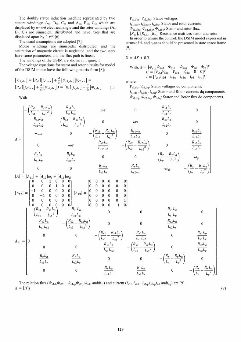
3.2.2. Principe of a fuzzy controller
The control by fuzzy logic permits to obtain a law of drive,
often very effective, without having a precise model of the
process, from a linguistic description of the behavior of the
system. Its approach is different the one of the automatic
classic, in the sense that it does not treat mathematical relations
well defined, but it exploits the knowledge of an expert. These
are expressed by means of conduct rules based on a symbolic
vocabulary and manipulate inferences with several rules using
the fuzzy operators AND, OR, THEN, applied to linguistic
variables. [15].
Figure 2. Structure interns of a system Fuzzy
Wo inputs of speed fuzzy controller are chosen, the speed
error (e) and its variation ∆e:
𝑒 = 𝜔𝑟∗ − 𝜔𝑟 (13)
𝛥𝑒(𝑘) = 𝑒(𝑘) − 𝑒(𝑘 − 1) (14)
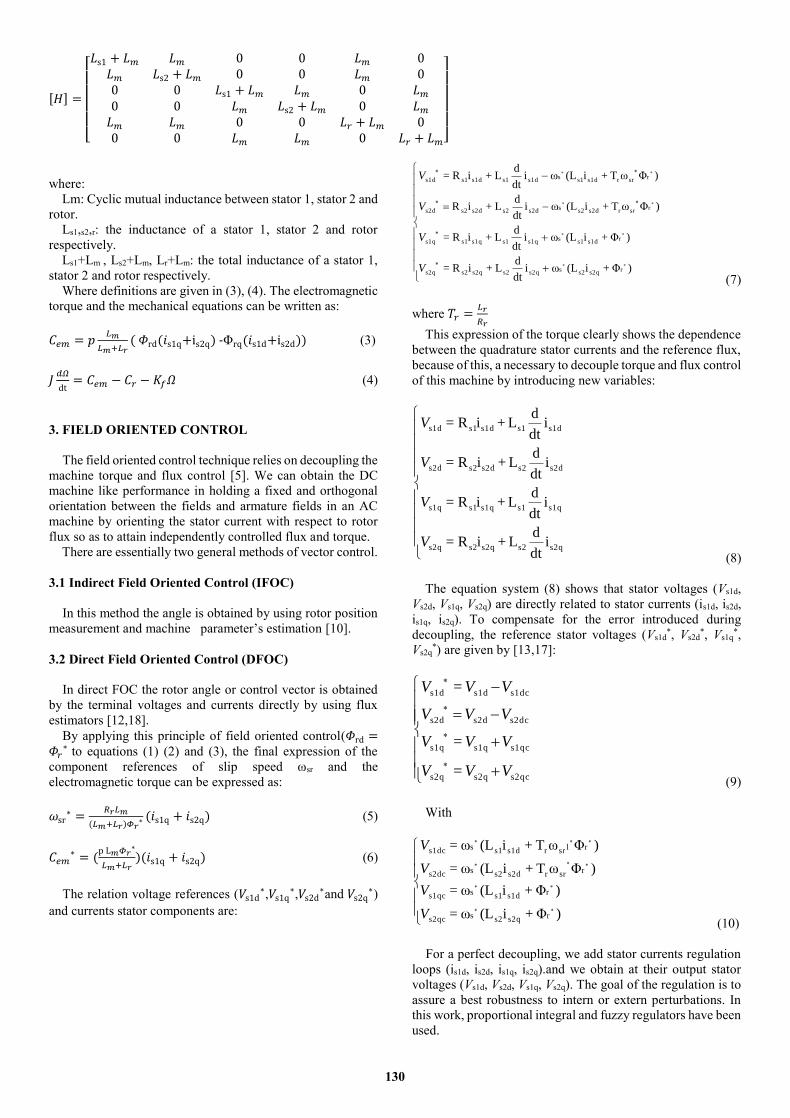
Figure 3 in which the linguistic variables are represented by
NB (Negative Big), NM (Negative Medium), NS (Negative
Small), Z (Zero), PS (Positive Small), PM (Positive Medium)
and PB (Positive Big).
Figure 3. Fuzzification with seven memberships
Table 1 shows one of possible control rules based on seven
membership functions [16].
Table 1. The fuzzy control rule bases
e
∆e NB NM NS ZE PS PM PB
NB NB NB NB NB NM NS ZE
NM NB NB NB NM NS ZE PS
NS NB NB NM NS ZE PS PM
ZE NB NM NS ZE PS PM PB
PS NM NS ZE PS PM PB PB
PM NS ZE PS PM PB PB PB
PB ZE PS PM PB PB PB PB
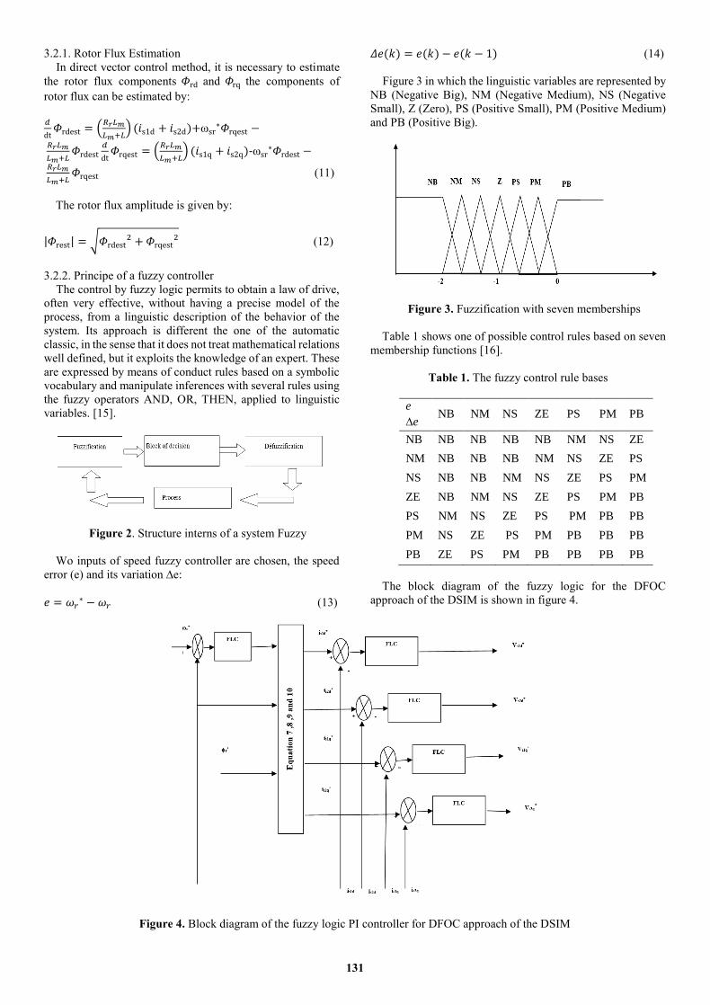
The block diagram of the fuzzy logic for the DFOC
approach of the DSIM is shown in figure 4.
Figure 4. Block diagram of the fuzzy logic PI controller for DFOC approach of the DSIM
131
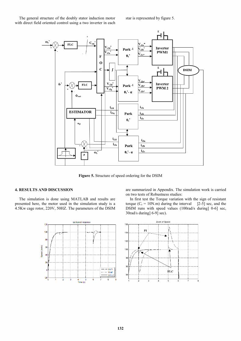
The general structure of the doubly stator induction motor
with direct field oriented control using a two inverter in each
star is represented by figure 5.
Figure 5. Structure of speed ordering for the DSIM
4. RESULTS AND DISCUSSION
The simulation is done using MATLAB and results are
presented here, the motor used in the simulation study is a
4.5Kw cage rotor, 220V, 50HZ. The parameters of the DSIM
are summarized in Appendix. The simulation work is carried
on two tests of Robustness studies:
In first test the Torque variation with the sign of resistant
torque (Cr = 10N.m) during the interval ]2-5] sec, and the
DSIM runs with speed values (100rad/s during] 0-6] sec,
30rad/s during] 6-9] sec).
132
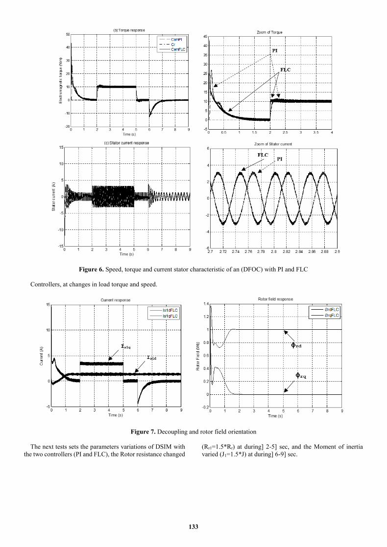
Figure 6. Speed, torque and current stator characteristic of an (DFOC) with PI and FLC
Controllers, at changes in load torque and speed.
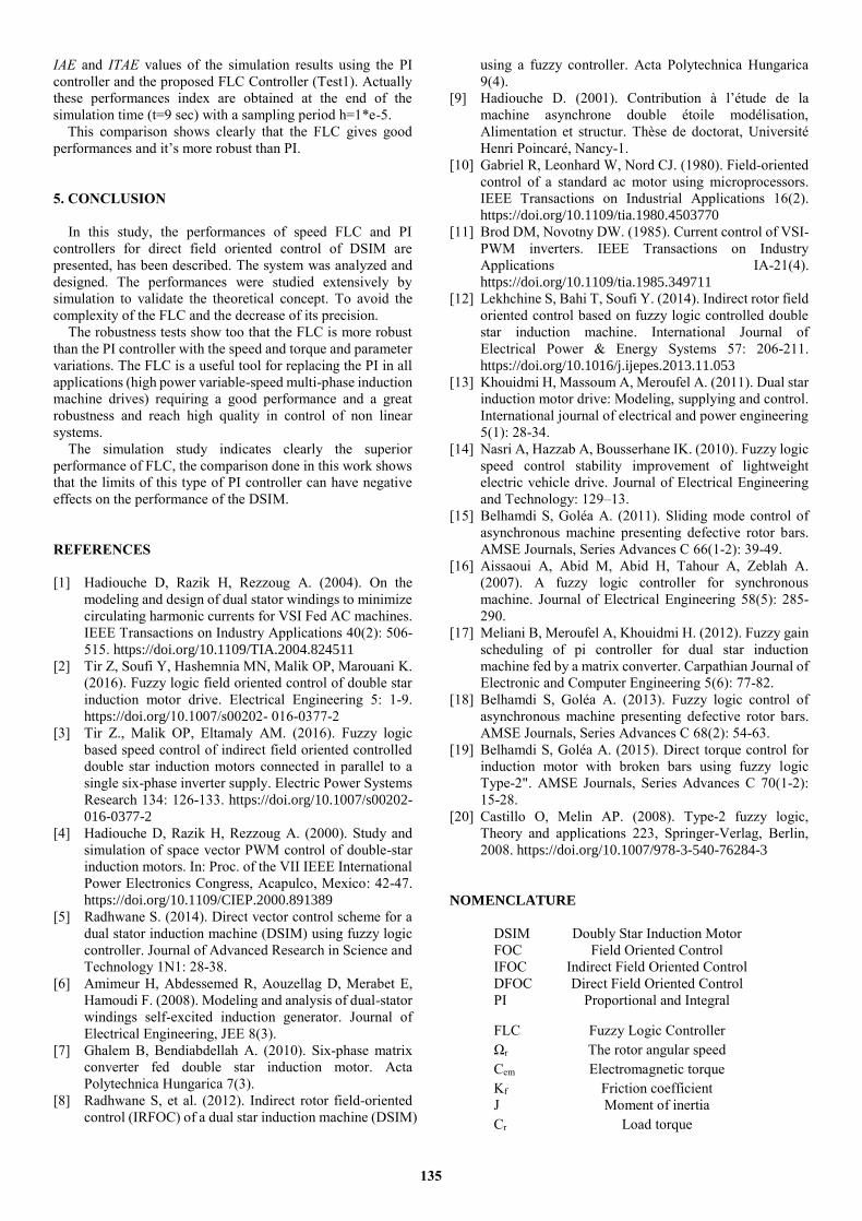
Figure 7. Decoupling and rotor field orientation
The next tests sets the parameters variations of DSIM with
the two controllers (PI and FLC), the Rotor resistance changed
(Rr1=1.5*Rr) at during] 2-5] sec, and the Moment of inertia
varied (J1=1.5*J) at during] 6-9] sec.
133
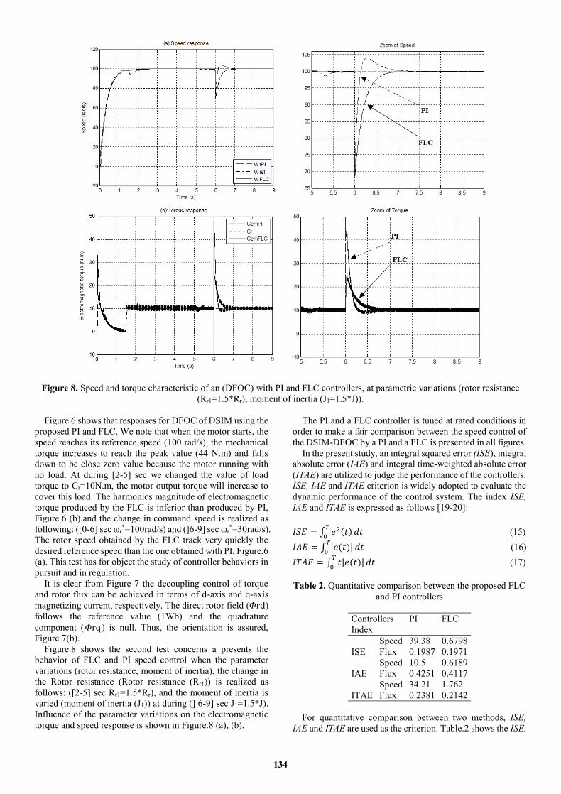
Figure 8. Speed and torque characteristic of an (DFOC) with PI and FLC controllers, at parametric variations (rotor resistance
(Rr1=1.5*Rr), moment of inertia (J1=1.5*J)).
Figure 6 shows that responses for DFOC of DSIM using the
proposed PI and FLC, We note that when the motor starts, the
speed reaches its reference speed (100 rad/s), the mechanical
torque increases to reach the peak value (44 N.m) and falls
down to be close zero value because the motor running with
no load. At during [2-5] sec we changed the value of load
torque to Cr=10N.m, the motor output torque will increase to
cover this load. The harmonics magnitude of electromagnetic
torque produced by the FLC is inferior than produced by PI,
Figure.6 (b).and the change in command speed is realized as
following: ([0-6] sec ωr*=100rad/s) and (]6-9] sec ωr
*=30rad/s).
The rotor speed obtained by the FLC track very quickly the
desired reference speed than the one obtained with PI, Figure.6
(a). This test has for object the study of controller behaviors in
pursuit and in regulation.
It is clear from Figure 7 the decoupling control of torque
and rotor flux can be achieved in terms of d-axis and q-axis
magnetizing current, respectively. The direct rotor field (𝛷rd)
follows the reference value (1Wb) and the quadrature
component (𝛷rq) is null. Thus, the orientation is assured,
Figure 7(b).
Figure.8 shows the second test concerns a presents the
behavior of FLC and PI speed control when the parameter
variations (rotor resistance, moment of inertia), the change in
the Rotor resistance (Rotor resistance (Rr1)) is realized as
follows: ([2-5] sec Rr1=1.5*Rr), and the moment of inertia is
varied (moment of inertia (J1)) at during (] 6-9] sec J1=1.5*J).
Influence of the parameter variations on the electromagnetic
torque and speed response is shown in Figure.8 (a), (b).
The PI and a FLC controller is tuned at rated conditions in
order to make a fair comparison between the speed control of
the DSIM-DFOC by a PI and a FLC is presented in all figures.
In the present study, an integral squared error (ISE), integral
absolute error (IAE) and integral time-weighted absolute error
(ITAE) are utilized to judge the performance of the controllers.
ISE, IAE and ITAE criterion is widely adopted to evaluate the
dynamic performance of the control system. The index ISE,
IAE and ITAE is expressed as follows [19-20]:
𝐼𝑆𝐸 = ∫ 𝑒2(𝑡)𝑇
0𝑑𝑡 (15)
𝐼𝐴𝐸 = ∫ |𝑒(𝑡)|𝑇
0𝑑𝑡 (16)
𝐼𝑇𝐴𝐸 = ∫ 𝑡|𝑒(𝑡)|𝑇
0𝑑𝑡 (17)
Table 2. Quantitative comparison between the proposed FLC
and PI controllers
Controllers
Index
PI FLC
ISE
Speed 39.38 0.6798
Flux 0.1987 0.1971
IAE
Speed 10.5 0.6189
Flux 0.4251 0.4117
ITAE
Speed 34.21 1.762
Flux 0.2381 0.2142
For quantitative comparison between two methods, ISE,
IAE and ITAE are used as the criterion. Table.2 shows the ISE,
134
IAE and ITAE values of the simulation results using the PI
controller and the proposed FLC Controller (Test1). Actually
these performances index are obtained at the end of the
simulation time (t=9 sec) with a sampling period h=1*e-5.
This comparison shows clearly that the FLC gives good
performances and it’s more robust than PI.
5. CONCLUSION
In this study, the performances of speed FLC and PI
controllers for direct field oriented control of DSIM are
presented, has been described. The system was analyzed and
designed. The performances were studied extensively by
simulation to validate the theoretical concept. To avoid the
complexity of the FLC and the decrease of its precision.
The robustness tests show too that the FLC is more robust
than the PI controller with the speed and torque and parameter
variations. The FLC is a useful tool for replacing the PI in all
applications (high power variable-speed multi-phase induction
machine drives) requiring a good performance and a great
robustness and reach high quality in control of non linear
systems.
The simulation study indicates clearly the superior
performance of FLC, the comparison done in this work shows
that the limits of this type of PI controller can have negative
effects on the performance of the DSIM.
REFERENCES
[1] Hadiouche D, Razik H, Rezzoug A. (2004). On the
modeling and design of dual stator windings to minimize
circulating harmonic currents for VSI Fed AC machines.
IEEE Transactions on Industry Applications 40(2): 506-
515. https://doi.org/10.1109/TIA.2004.824511
[2] Tir Z, Soufi Y, Hashemnia MN, Malik OP, Marouani K.
(2016). Fuzzy logic field oriented control of double star
induction motor drive. Electrical Engineering 5: 1-9.
https://doi.org/10.1007/s00202- 016-0377-2
[3] Tir Z., Malik OP, Eltamaly AM. (2016). Fuzzy logic
based speed control of indirect field oriented controlled
double star induction motors connected in parallel to a
single six-phase inverter supply. Electric Power Systems
Research 134: 126-133. https://doi.org/10.1007/s00202-
016-0377-2
[4] Hadiouche D, Razik H, Rezzoug A. (2000). Study and
simulation of space vector PWM control of double-star
induction motors. In: Proc. of the VII IEEE International
Power Electronics Congress, Acapulco, Mexico: 42-47.
https://doi.org/10.1109/CIEP.2000.891389
[5] Radhwane S. (2014). Direct vector control scheme for a
dual stator induction machine (DSIM) using fuzzy logic
controller. Journal of Advanced Research in Science and
Technology 1N1: 28-38.
[6] Amimeur H, Abdessemed R, Aouzellag D, Merabet E,
Hamoudi F. (2008). Modeling and analysis of dual-stator
windings self-excited induction generator. Journal of
Electrical Engineering, JEE 8(3).
[7] Ghalem B, Bendiabdellah A. (2010). Six-phase matrix
converter fed double star induction motor. Acta
Polytechnica Hungarica 7(3).
[8] Radhwane S, et al. (2012). Indirect rotor field-oriented
control (IRFOC) of a dual star induction machine (DSIM)
using a fuzzy controller. Acta Polytechnica Hungarica
9(4).
[9] Hadiouche D. (2001). Contribution à l’étude de la
machine asynchrone double étoile modélisation,
Alimentation et structur. Thèse de doctorat, Université
Henri Poincaré, Nancy-1.
[10] Gabriel R, Leonhard W, Nord CJ. (1980). Field-oriented
control of a standard ac motor using microprocessors.
IEEE Transactions on Industrial Applications 16(2).
https://doi.org/10.1109/tia.1980.4503770
[11] Brod DM, Novotny DW. (1985). Current control of VSI-
PWM inverters. IEEE Transactions on Industry
Applications IA-21(4).
https://doi.org/10.1109/tia.1985.349711
[12] Lekhchine S, Bahi T, Soufi Y. (2014). Indirect rotor field
oriented control based on fuzzy logic controlled double
star induction machine. International Journal of
Electrical Power & Energy Systems 57: 206-211.
https://doi.org/10.1016/j.ijepes.2013.11.053
[13] Khouidmi H, Massoum A, Meroufel A. (2011). Dual star
induction motor drive: Modeling, supplying and control.
International journal of electrical and power engineering
5(1): 28-34.
[14] Nasri A, Hazzab A, Bousserhane IK. (2010). Fuzzy logic
speed control stability improvement of lightweight
electric vehicle drive. Journal of Electrical Engineering
and Technology: 129–13.
[15] Belhamdi S, Goléa A. (2011). Sliding mode control of
asynchronous machine presenting defective rotor bars.
AMSE Journals, Series Advances C 66(1-2): 39-49.
[16] Aissaoui A, Abid M, Abid H, Tahour A, Zeblah A.
(2007). A fuzzy logic controller for synchronous
machine. Journal of Electrical Engineering 58(5): 285-
290.
[17] Meliani B, Meroufel A, Khouidmi H. (2012). Fuzzy gain
scheduling of pi controller for dual star induction
machine fed by a matrix converter. Carpathian Journal of
Electronic and Computer Engineering 5(6): 77-82.
[18] Belhamdi S, Goléa A. (2013). Fuzzy logic control of
asynchronous machine presenting defective rotor bars.
AMSE Journals, Series Advances C 68(2): 54-63.
[19] Belhamdi S, Goléa A. (2015). Direct torque control for
induction motor with broken bars using fuzzy logic
Type-2". AMSE Journals, Series Advances C 70(1-2):
15-28.
[20] Castillo O, Melin AP. (2008). Type-2 fuzzy logic,
Theory and applications 223, Springer-Verlag, Berlin,
2008. https://doi.org/10.1007/978-3-540-76284-3
NOMENCLATURE
DSIM Doubly Star Induction Motor
FOC Field Oriented Control
IFOC Indirect Field Oriented Control
DFOC Direct Field Oriented Control
PI Proportional and Integral
FLC Fuzzy Logic Controller
Ωr The rotor angular speed
Cem Electromagnetic torque
Kf Friction coefficient
J Moment of inertia
Cr Load torque
135

θs Angle between stator and rotor flux
P Number of pole pairs
ωsr* Slip speed reference
APPENDIX
Table 3. DSIM parameters (Radhwane S. et al 2012)
DSIM Mechanical Power 4.5 kW
Nominal voltage 220 V
Frequency 50 Hz
Pole pair number 1
Stators 1,2 resistances 3.72 Ω
Rotor resistance 2.12 Ω
Stators 1,2 self inductances 0.022 H
Rotor inductance 0.006 H
Mutual inductance 0.3672 H
Moment of inertia 0.0625Nms2/rad
Friction coefficient 0.001Nms/rad
136
Recommended