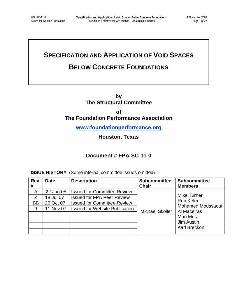
FPA-SC-11-0 Specification and Application of Void Spaces Below Concrete Foundations 11 November 2007 Issued for Website Publication Foundation Performance Association - Structural Committee Page 1 of 22
SPECIFICATION AND APPLICATION OF VOID SPACES
BELOW CONCRETE FOUNDATIONS
by The Structural Committee
of The Foundation Performance Association
www.foundationperformance.org
Houston, Texas
Document # FPA-SC-11-0
ISSUE HISTORY (Some internal committee issues omitted)
Rev#
Date Description Subcommittee Chair
Subcommittee Members
A 22 Jun 05 Issued for Committee Review
Z 18 Jul 07 Issued for FPA Peer Review
BB 26 Oct 07 Issued for Committee Review
0 11 Nov 07 Issued for Website Publication
Michael Skoller
Mike Turner Ron Kelm Mohamed Moussaoui Al Maceiras Mari Mes Jim Austin Karl Breckon
FPA-SC-11-0 Specification and Application of Void Spaces Below Concrete Foundations 11 November 2007 Issued for Website Publication Foundation Performance Association - Structural Committee Page 2 of 22
PREFACE
This document was written by the Structural Committee's FPA-SC-11 ad hoc subcommittee
and has been peer reviewed by the Foundation Performance Association (FPA). This
document is published as FPA-SC-11 Revision 0 (or, FPA-SC-11-0) and is made freely
available to the public at www.foundationperformance.org so all may have access to the
information. To ensure this document remains as current as possible, it may be periodically
updated under the same document number but with higher revision numbers such at 1, 2, etc.
The Structural Committee is a permanent committee of the Foundation Performance
Association. At the time of writing this document, the Structural Committee was chaired by
Ron Kelm and 25 to 35 members were active on the committee. The committee sanctioned
this paper and formed a subcommittee to write this document. The subcommittee chair and
members are listed on the cover sheet of this document and are considered this document's co-
authors.
Suggestions for improvement of this document should be directed to the current chair of the
Structural Committee. If sufficient comments are received to warrant a revision, the
committee may form a new subcommittee to revise this document. If the revised document
successfully passes FPA peer review, it will be published on the FPA website and the
previous revision will be deleted.
The intended audiences for the use of this document are engineers, architects, builders,
foundation contractors, owners, and others that may be involved in the design of foundations
that are located in the southeast region of the state of Texas, and primarily within the City of
Houston and its surrounding metropolitan area. However, much of the information discussed
may also apply to other geographical areas with Expansive Soils.
This document was created with generously donated time in an effort to improve the
performance of foundations. The Foundation Performance Association and its members make
no warranty, expressed or implied regarding the accuracy of the information contained herein
and will not be liable for any damages, including consequential damages, resulting from the
use of this document. Each project should be investigated for its individual characteristics to
permit appropriate application of the material contained herein. Please refer to the website at
www.foundationperformance.org for other information pertaining to this document or other
FPA publications.
FPA-SC-11-0 Specification and Application of Void Spaces Below Concrete Foundations 11 November 2007 Issued for Website Publication Foundation Performance Association - Structural Committee Page 3 of 22
GLOSSARY
• Carton Forms are shoring elements designed to provide a Void Space between
Expansive Soils and foundation systems, while providing a temporary support formwork
for the weight of concrete and construction loads during placement until the concrete sets
to the point that it can span between its permanent supports. See section 2.0 for additional
information.
• Expansive Soils per 2006 International 1Building Code [1] Section 1802.3.2 and 2006
International Residential Code [2] Section R403.1.8. are “Soils meeting all four of the
following provisions shall be considered expansive, except that tests to show compliance
with Items 1, 2 and 3 shall not be required if the test prescribed in item 4 is conducted:
1. Plasticity Index (PI) of 15 or greater, determined in accordance with ASTM D
4318.
2. More than 10 percent of the soil particles pass a No. 200 sieve (75 m),
determined in accordance with ASTM D 422.
3. More than 10 percent of the soil particles are less than 5 micrometers in size,
determined in accordance with ASTM D 422.
4. Expansion Index greater than 20, determined in accordance with ASTM D
4829.”
• Heave is the upward movement of an underlying supporting soil stratum due to the
addition of water to an unsaturated Expansive Soil within the moisture active zone. When
moisture is added to the soil, expansion occurs within the structure of the soil, and the
corresponding area of the foundation and Superstructure move upward. Heave most
commonly occurs within clayey soils with an available moisture source.
• Plasticity Index (PI) is the numeric difference between the liquid limit and the plastic
limit. It is a scale used to measure the potential for volume change for Expansive Soils.
Soil with a PI less than 15 is considered non-expansive, soil with a PI between 15 and 30
are considered to be moderately expansive, and soil with a PI above 30 is considered
highly expansive.
• Potential Upward Movement (PUM) is the potential amount of upward movement of
the site-specific soils directly below the foundation. PUM is typically provided in
geotechnical reports and is based on moisture changes from dry to saturated conditions as
well as in-situ to saturated conditions. Common methods for determining PUM include
the use of suction tests, swell tests, and the potential vertical rise (PVR) method.
• Slab Area is the portion of a Structural Slab spanning between the grade beams and/or
piers.
• Soil Retainers are sheets placed vertically adjacent to the degradable voids under the
grade beams and are used to resist the lateral soil pressures that can invade the voided
space during and after construction. Soil Retainers are typically comprised of HDPE (high
FPA-SC-11-0 Specification and Application of Void Spaces Below Concrete Foundations 11 November 2007 Issued for Website Publication Foundation Performance Association - Structural Committee Page 4 of 22
density polyethylene) or other materials that are non-degradable and are not adversely
affected by moisture.
• Structural Slab, as defined for this paper, is a foundation system consisting of a
structural reinforced concrete slab with Carton Forms that create a space that separates the
slab from the surface soils. A slab is designated as a Structural Slab when the slab is
designed to span between reinforced concrete grade beams that are supported entirely by
deep support systems or piers if the slab is unstiffened, i.e. a foundation of uniform
thickness. Deep support systems are foundations having deep components such as drilled
piers or piles that extend below the moisture active zone of the soils. Deep support
systems function to limit the vertical movements of the building by providing support in a
non-active soil stratum. For further details, see Document No. FPA-SC-01, Foundation
Design Options for Residential and Other Low-Rise Buildings on Expansive Soils [4].
• Superstructure is comprised of building components above the foundation such as the
structural framing and the architectural coverings for the floor, walls, ceilings, and roof.
• Void Spaces are gaps designed to provide an intended buffer zone or clearance between
Expansive Soils and a concrete foundation in order that Heave can occur without
imposing detrimental uplift pressures to the foundation.
• Void Space System is the complete assembly and use of components specified by the
foundation design engineer in order to create the designed Void Space.
• Wax Coated describes a process that is used to coat only the exterior liner surface of
corrugated Carton Forms. This process will temporarily help maintain structural integrity
should the forms come in contact with excessive moisture during foundation construction.
• Wax Impregnated describes the result of a process that saturates (with wax) individual
papers used to manufacture Carton Forms. Fully Wax Impregnated describes the result of
a manufacturing process where all paper components (e.g., liners and mediums) are Wax
Impregnated. This process allows the Carton Forms to maintain some structural integrity
should the forms come in contact with water during foundation construction. Fully Wax
Impregnated paper is highly resistant to initial moisture contact, is not biodegradable, and
holds its shape when wet with no imposed load.
FPA-SC-11-0 Specification and Application of Void Spaces Below Concrete Foundations 11 November 2007 Issued for Website Publication Foundation Performance Association - Structural Committee Page 5 of 22
TABLE OF CONTENTS
1.0 INTRODUCTION................................................................................................. 6
2.0 VOID SPACE SYSTEM TYPES .......................................................................... 7
2.1 DEGRADABLE VOID SPACE (CARTON FORM) SYSTEMS..................... 7
2.2 COLLAPSIBLE VOID SPACE SYSTEMS................................................... 7
2.3 NON-COLLAPSIBLE VOID SPACE SYSTEMS.......................................... 7
3.0 DESIGN OF VOID SPACE SYSTEMS................................................................ 8
3.1 VOID SPACE (CARTON FORM) SYSTEMS UNDER SLAB AREAS......... 8
3.2 VOID SPACE SYSTEMS UNDER GRADE BEAMS ................................... 9
3.3 DESIGN CONSIDERATIONS.................................................................... 10
3.3.1 Earth-Formed Beams....................................................................................... 11 3.3.2 Degradable Carton Forms (under Slab Areas, grade beams, and pier caps)................. 11 3.3.3 Collapsible Void Space Materials (under grade beams only) .................................. 11 3.3.4 Non-Collapsible Void Space Materials (under grade beams only)........................... 11
3.4 DESIGN LOADS........................................................................................ 12
3.5 FORMS AROUND THE TOPS OF THE PIERS......................................... 13
3.6 DESIGN PROCEDURE ............................................................................. 14
3.7 CONSIDERATIONS FOR UNDER-SLAB UTILITIES................................ 14
4.0 SPECIFICATIONS FOR VOID SPACE MATERIALS ....................................... 15
4.1 SPECIFICATIONS FOR ALL VOID SPACE MATERIAL TYPES ............. 15
4.2 DEGRADABLE VOID SPACE (CARTON FORM) MATERIALS............... 16
4.3 COLLAPSIBLE VOIDS (UNDER GRADE BEAMS ONLY)....................... 17
4.4 NON-COLLAPSIBLE VOID SYSTEMS (UNDER GRADE BEAMS ONLY) ....... 18
4.5 TRAPEZOIDAL CARTON FORMS ........................................................... 18
4.6 TESTING REQUIREMENTS...................................................................... 19
4.7 SUBMITTALS............................................................................................ 20
5.0 HANDLING AND INSTALLATION OF VOID SPACE SYSTEMS..................... 20
5.1 ONSITE VOID SPACE SYSTEMS PROTECTION .................................... 20
5.2 INSTALLATION......................................................................................... 20
6.0 REFERENCES .................................................................................................. 22
FPA-SC-11-0 Specification and Application of Void Spaces Below Concrete Foundations 11 November 2007 Issued for Website Publication Foundation Performance Association - Structural Committee Page 6 of 22
1.0 INTRODUCTION
The need for this document was prompted by a concern in the industry about the effectiveness
of Void Space Systems in isolating foundations from Expansive Soils. Void Space Systems
are designed to provide an intended buffer zone or clearance between Expansive Soils and a
concrete foundation system, while providing a support formwork for the weight of concrete
and construction loads during placement until the concrete has sufficient strength to span
between supports. At sites where Expansive Soil below the foundation has the potential to
swell, Void Space Systems are designed to isolate the foundation from Heave of the
underlying soil.
The scope of this document is to provide guidance in the design, specification, and installation
of Void Space Systems under residential and other low-rise building foundations, typically
called lightly loaded foundations, which are founded on Expansive Soils. These buildings
may include but are not necessarily limited to houses, garages, apartment and condominium
buildings, restaurants, schools, churches, and other similar structures.
Void Space Systems have been used for decades. The intent has been to provide an intended
buffer zone or clearance beneath the foundation for the Expansive Soils to Heave into without
applying detrimental upward pressure to the bottom of the foundation. In the mid-1990’s,
however, members of the Foundation Performance Association and others in the structural,
geotechnical and forensic community in the Houston Texas area discovered some foundations
designed with Void Spaces beneath only the grade beams had experienced damaging
movement. The general consensus in the Houston Texas area at that time was that the
presence of the Carton Forms allowed water to accumulate below the foundation, causing
Heave. Most concerned professionals concluded that it might be better to simply eliminate
the use of Void Spaces that were used only below the grade beams.
Until the mid-1990’s it was customary to use Void Spaces below grade beams but not below
the Slab Area. Since that time many engineers have specified that Void Spaces be installed
under the Slab Area only when designing a Structural Slab with Void Space. Presently, some
performance problems associated with foundations isolated from Expansive Soils using Void
Spaces continue. This document was written to help clarify possible causes of foundation
problems and present a guideline for the use of Void Space Systems under foundations in an
effort to improve future performance.
This committee recommends in this document to eliminate utilizing Void Spaces under grade
beams only. The two alternatives recommended in this document are: 1) Void Space Systems
under Slab Areas only and 2) Void Space Systems under both Slab Areas and grade beams.
Section 2 of this paper provides detailed definitions of Void Space System materials. Section
3 discusses the design of Void Space Systems along with the advantages and disadvantages of
various void material types. Section 4 presents specifications for materials used to create Void
FPA-SC-11-0 Specification and Application of Void Spaces Below Concrete Foundations 11 November 2007 Issued for Website Publication Foundation Performance Association - Structural Committee Page 7 of 22
Spaces. Section 5 discusses the handling and installation of Void Space Systems. References
may be found in Section 6.
2.0 VOID SPACE SYSTEM TYPES
Several Void Space System types are discussed below. See Section 4.0 for material
specifications.
2.1 DEGRADABLE VOID SPACE (CARTON FORM) SYSTEMS
The type of Carton Forms most commonly used are degradable forms constructed of a
corrugated paper product arranged in an open cell configuration. The exterior surface of the
Carton Forms may be Wax Coated to temporarily resist moisture from the weather, soil,
and/or wet concrete. These forms are typically designed to gradually absorb ground moisture
and lose strength over a period of time, leaving a Void Space between the Expansive Soils
and the foundation.
If the soil below the foundation expands, the soil can then Heave into the space provided by
the Carton Forms without lifting or deforming the foundation. Course fill material under
Carton Forms should not be used because a capillary break may occur preventing moisture
migration to the degradable Carton Forms.
Only degradable Void Space (Carton Form) Systems should be used under Slab Areas.
2.2 COLLAPSIBLE VOID SPACE SYSTEMS
Collapsible Void Space Systems incorporate a non-degradable material designed to collapse
under Heave pressures (from the soil below) greater than the foundation and Superstructure
dead loads, but not collapse during foundation make-up and placement. Collapsible Void
Space Systems may be constructed of plastic, Wax Impregnated corrugated paper, or other
materials resistant to moisture but designed to collapse under the pressure of swelling soils.
Collapsible Void Space Systems should not be used under Slab Areas. The combination of the
dead load plus sustained live load and inherent stiffness of the typical Slab Area is not
sufficient to collapse this type of material and would thereby transfer the uplift forces through
the non-collapsed Void Space Systems to the above Slab Area.
2.3 NON-COLLAPSIBLE VOID SPACE SYSTEMS
Non-collapsible Void Space Systems incorporate material designed to maintain its original
structural integrity throughout the life of the foundation. This type of system provides a built-
in Void Space. Materials may be comprised of Fully Wax Impregnated corrugated paper
products, Styrofoam, plastics or other non-degradable products. See section 4.4 for an
example.
FPA-SC-11-0 Specification and Application of Void Spaces Below Concrete Foundations 11 November 2007 Issued for Website Publication Foundation Performance Association - Structural Committee Page 8 of 22
Non-Collapsible Void Space Systems should not be used under Slab Areas. This is because
the combination of operational loads and inherent stiffness of the typical Slab Area is not
sufficient to collapse this system and thereby allows transfer of uplift forces through the non-
collapsible support structure of the Void Space Systems to the above Slab Area.
3.0 DESIGN OF VOID SPACE SYSTEMS
This section includes the design of Void Spaces under various load criteria in conjunction
with the Void Space System material type (see Section 2.0 for definitions). This section also
includes some advantages and disadvantages of Void Space Systems under slabs, under grade
beams, and around piers.
Carton Forms under foundations typically support uncured concrete during construction,
creating a Void Space that isolates the foundation from the underlying soil. The depth of the
Void Space, which has been known to range from two to twenty-four inches (2"-24"), is a
function of the PUM of the underlying soils. Typically, deeper Void Spaces are associated
with more Expansive Soil. The geotechnical engineer should specify the net depth of the Void
Space and the PUM. In the case of collapsible Void Space Systems, the net depth is the non-
collapsed depth minus the collapsed depth. In the case of non-collapsible Void Space
Systems, the net depth is increased appropriately to provide the same net Void Space volume.
When using Carton Forms under the Slab Area, Void Spaces under the grade beams should
also be used when the uplift forces of the Expansive Soils are predicted to be greater than the
dead plus sustained live loads of the foundation and Superstructure that are transferred to the
grade beams.
3.1 VOID SPACE (CARTON FORM) SYSTEMS UNDER SLAB AREAS
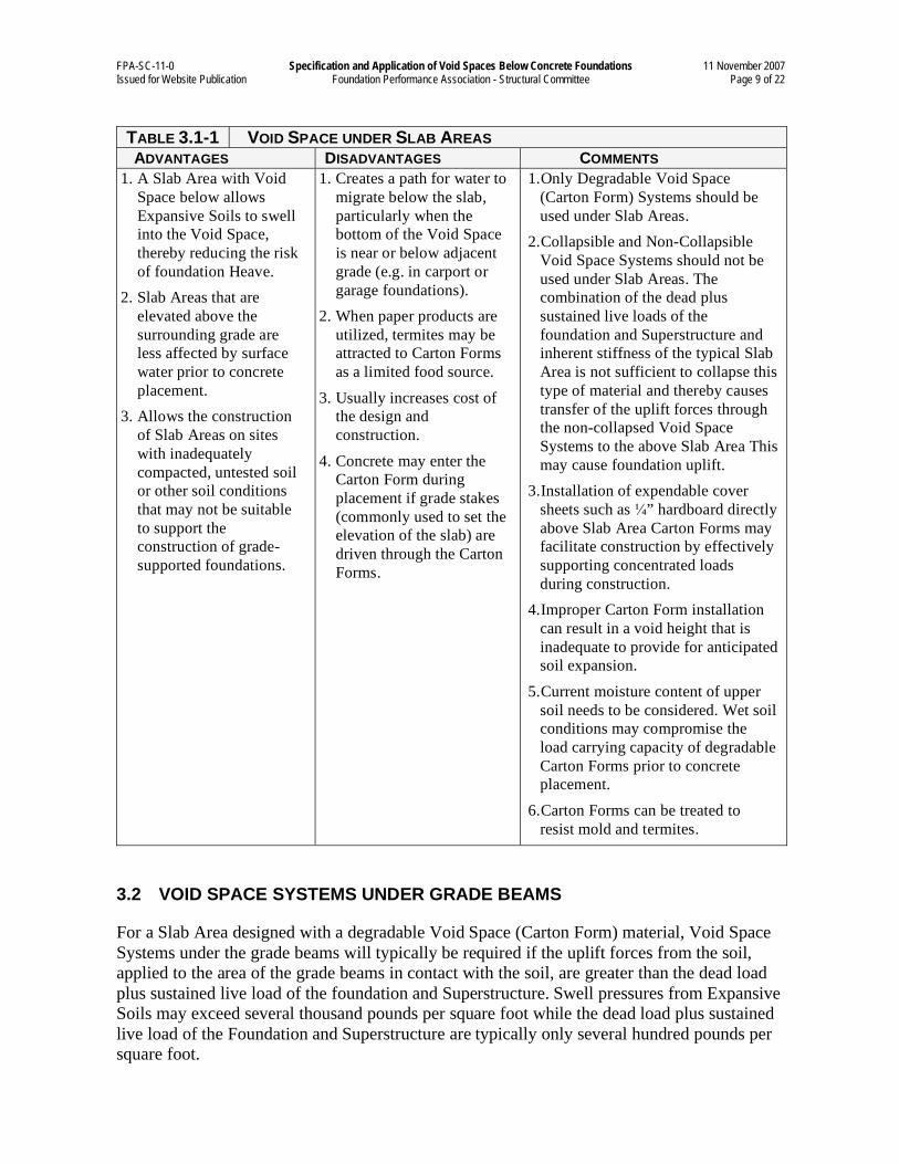
Only degradable Void Space (Carton Form) Systems should be used under Slab Areas. The
advantages, disadvantages and comments on the use of Carton Forms under Slab Areas are
addressed in Table 3.1-1, below. In order for the Carton Forms to degrade, the contractor shall
ensure that no subgrade capillary breaks, such as gravel, plastic sheathing, and fill debris,
exist below the Void Space.
FPA-SC-11-0 Specification and Application of Void Spaces Below Concrete Foundations 11 November 2007 Issued for Website Publication Foundation Performance Association - Structural Committee Page 9 of 22
TABLE 3.1-1 VOID SPACE UNDER SLAB AREAS ADVANTAGES DISADVANTAGES COMMENTS
1. A Slab Area with Void
Space below allows
Expansive Soils to swell
into the Void Space,
thereby reducing the risk
of foundation Heave.
2. Slab Areas that are
elevated above the
surrounding grade are
less affected by surface
water prior to concrete
placement.
3. Allows the construction
of Slab Areas on sites
with inadequately
compacted, untested soil
or other soil conditions
that may not be suitable
to support the
construction of grade-
supported foundations.
1. Creates a path for water to
migrate below the slab,
particularly when the
bottom of the Void Space
is near or below adjacent
grade (e.g. in carport or
garage foundations).
2. When paper products are
utilized, termites may be
attracted to Carton Forms
as a limited food source.
3. Usually increases cost of
the design and
construction.
4. Concrete may enter the
Carton Form during
placement if grade stakes
(commonly used to set the
elevation of the slab) are
driven through the Carton
Forms.
1. Only Degradable Void Space
(Carton Form) Systems should be
used under Slab Areas.
2. Collapsible and Non-Collapsible
Void Space Systems should not be
used under Slab Areas. The
combination of the dead plus
sustained live loads of the
foundation and Superstructure and
inherent stiffness of the typical Slab
Area is not sufficient to collapse this
type of material and thereby causes
transfer of the uplift forces through
the non-collapsed Void Space
Systems to the above Slab Area This
may cause foundation uplift.
3. Installation of expendable cover
sheets such as ” hardboard directly
above Slab Area Carton Forms may
facilitate construction by effectively
supporting concentrated loads
during construction.
4. Improper Carton Form installation
can result in a void height that is
inadequate to provide for anticipated
soil expansion.
5. Current moisture content of upper
soil needs to be considered. Wet soil
conditions may compromise the
load carrying capacity of degradable
Carton Forms prior to concrete
placement.
6. Carton Forms can be treated to
resist mold and termites.
3.2 VOID SPACE SYSTEMS UNDER GRADE BEAMS
For a Slab Area designed with a degradable Void Space (Carton Form) material, Void Space
Systems under the grade beams will typically be required if the uplift forces from the soil,
applied to the area of the grade beams in contact with the soil, are greater than the dead load
plus sustained live load of the foundation and Superstructure. Swell pressures from Expansive
Soils may exceed several thousand pounds per square foot while the dead load plus sustained
live load of the Foundation and Superstructure are typically only several hundred pounds per
square foot.
FPA-SC-11-0 Specification and Application of Void Spaces Below Concrete Foundations 11 November 2007 Issued for Website Publication Foundation Performance Association - Structural Committee Page 10 of 22
As explained in Section 1.0, Void Spaces under the grade beams should only be used when
Carton Forms are also used under the Slab Area. Advantages, disadvantages and comments
of utilizing Carton Forms under grade beams are addressed in Table 3.2-1, below.
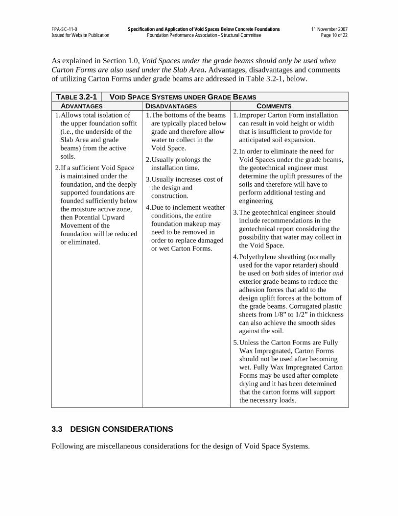
TABLE 3.2-1 VOID SPACE SYSTEMS UNDER GRADE BEAMS ADVANTAGES DISADVANTAGES COMMENTS
1. Allows total isolation of
the upper foundation soffit
(i.e., the underside of the
Slab Area and grade
beams) from the active
soils.
2. If a sufficient Void Space
is maintained under the
foundation, and the deeply
supported foundations are
founded sufficiently below
the moisture active zone,
then Potential Upward
Movement of the
foundation will be reduced
or eliminated.
1. The bottoms of the beams
are typically placed below
grade and therefore allow
water to collect in the
Void Space.
2. Usually prolongs the
installation time.
3. Usually increases cost of
the design and
construction.
4. Due to inclement weather
conditions, the entire
foundation makeup may
need to be removed in
order to replace damaged
or wet Carton Forms.
1. Improper Carton Form installation
can result in void height or width
that is insufficient to provide for
anticipated soil expansion.
2. In order to eliminate the need for
Void Spaces under the grade beams,
the geotechnical engineer must
determine the uplift pressures of the
soils and therefore will have to
perform additional testing and
engineering
3. The geotechnical engineer should
include recommendations in the
geotechnical report considering the
possibility that water may collect in
the Void Space.
4. Polyethylene sheathing (normally
used for the vapor retarder) should
be used on both sides of interior and
exterior grade beams to reduce the
adhesion forces that add to the
design uplift forces at the bottom of
the grade beams. Corrugated plastic
sheets from 1/8” to 1/2” in thickness
can also achieve the smooth sides
against the soil.
5. Unless the Carton Forms are Fully
Wax Impregnated, Carton Forms
should not be used after becoming
wet. Fully Wax Impregnated Carton
Forms may be used after complete
drying and it has been determined
that the carton forms will support
the necessary loads.
3.3 DESIGN CONSIDERATIONS
Following are miscellaneous considerations for the design of Void Space Systems.
FPA-SC-11-0 Specification and Application of Void Spaces Below Concrete Foundations 11 November 2007 Issued for Website Publication Foundation Performance Association - Structural Committee Page 11 of 22
3.3.1 Earth-Formed Beams
If the foundation design engineer desires earth-formed grade beams without a Void Space
below the grade beams, the following design procedure should be considered:
a) Determine the maximum uplift forces of the soil and compare the capacity of the grade
beams with that force applied to the bottom of the grade beams. If the dead load on the
beam is equal to or greater than the uplift force, no additional design is necessary. If
the uplift force is greater, the grade beams need to be designed for this upward force
minus the dead load, and the piers should then be designed for the proper depth below
the moisture active zone to resist this uplift.
b) There are two uplift forces to be considered: bearing on the bottom of the grade beams
and side friction between the soil and sides of the beam. One method of determining
these forces is to provide swell tests to determine the surcharge needed for zero swell
and use the shear capacity of the soil for the side friction. The actual determination of
these forces is not in the scope of this document.
c) It would be a reasonable assumption that, if the above items were accounted for and
the actual forces are the same or lower than assumed, Void Space would not be
necessary under the grade beams.
The following sections present comments on the design of Void Space Systems:
3.3.2 Degradable Carton Forms (under Slab Areas, grade beams, and pier caps)
The collapsed or degraded height of the Carton Form materials is important for the design of
the gross vertical height of the Void Space. The gross vertical height of the Void Space should
include the collapsed or deformed height plus the required Void Space height dictated by the
geotechnical engineer.
3.3.3 Collapsible Void Space Materials (under grade beams only)
The Void Space height dictated by the geotechnical engineer should be increased by the
collapsed height of the Void Space material.
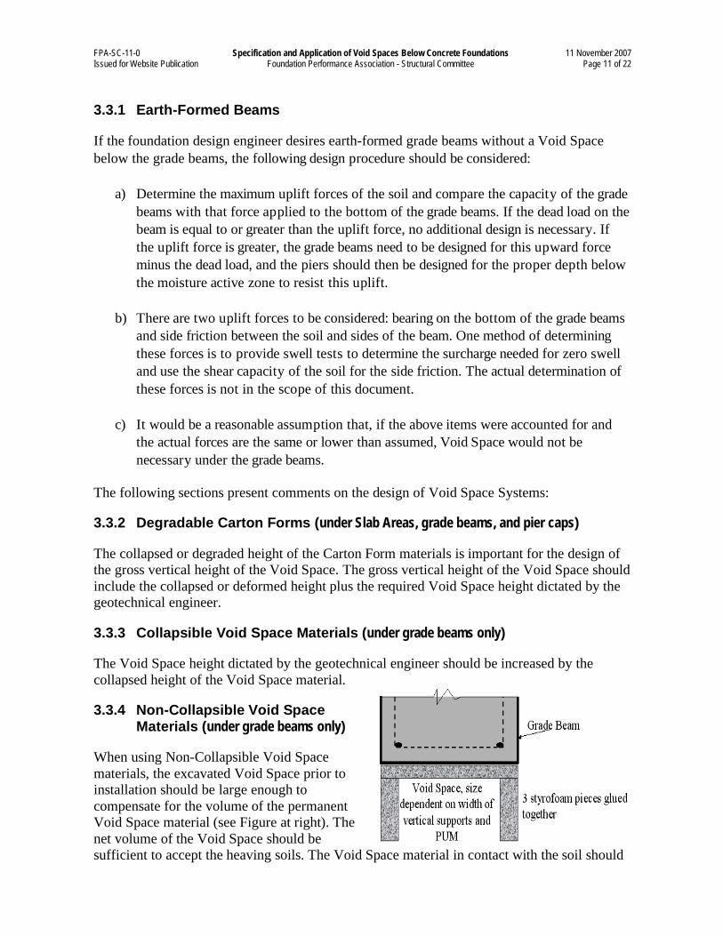
3.3.4 Non-Collapsible Void Space Materials (under grade beams only)
When using Non-Collapsible Void Space
materials, the excavated Void Space prior to
installation should be large enough to
compensate for the volume of the permanent
Void Space material (see Figure at right). The
net volume of the Void Space should be
sufficient to accept the heaving soils. The Void Space material in contact with the soil should
FPA-SC-11-0 Specification and Application of Void Spaces Below Concrete Foundations 11 November 2007 Issued for Website Publication Foundation Performance Association - Structural Committee Page 12 of 22
be able to support the wet weight of the concrete grade beams above but should not be able to
support the dead plus sustained live loads of the foundation and Superstructure.
3.4 DESIGN LOADS
All Void Space System products shall be capable of supporting the construction loads until
the concrete sets and becomes self-supporting while maintaining the design Void Space
(between the soil and the concrete) as indicated on the foundation design drawings. In
addition to the weight of the wet concrete construction loads include, as a minimum,
personnel and equipment during the construction process and the concentrated loads from
reinforcing steel chairs.
The following load specifications as shown in Table 3.4-1 should be given to the Carton Form
supplier:
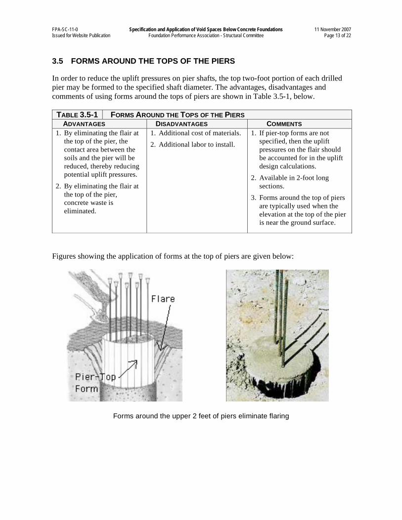
TABLE 3.4-1 REQUIRED DESIGN LOADS FOR VOID SPACE SYSTEMS
VOID SPACE SYSTEM MATERIAL TYPE
1
CRITERION CONDITION1, 3
NON-DEGRADABLE
DEGRADABLE
COLLAPSIBLE2 NON-
COLLAPSIBLE
Slabs with t 12” thick 600 Do not use Do not use
Slabs with t > 12” 456 + 12t Do not use Do not use
Beams with d 36” 1000 600 600
Minimum Initial Ultimate
Uniform Load Collapse
Pressure (as shipped, dry)
[PSF] Beams with d > 36” 568 + 12d 168 + 12d 168 + 12d
Slabs with t 12” thick 1500 Do not use Do not use
Slabs with t > 12” 1356 + 12t Do not use Do not use
Beams with d 36” 1500 1000 No limit
Maximum Initial Ultimate
Uniform Collapse Pressure
(as shipped, dry) [PSF] Beams with d > 36” 1068 + 12d 568 + 12d No limit
Slabs with t 12” thick 12t Do not use Do not use
Slabs with t > 12” 12t Do not use Do not use
Beams with d 36” 12d 1000 No limit
Maximum Final Ultimate
Uniform Collapse Pressure
(at 100% humidity for 7
days) [PSF] Beams with d > 36” 12d 568 + 12d No limit
Notes:
1. t = slab thickness [inches]; d = grade beam depth [inches], measured from the top of the slab
to the bottom of the beam
2. The foundation design engineer should verify the maximum ultimate collapse pressure.
3. The slab values should also be used for pier caps.
FPA-SC-11-0 Specification and Application of Void Spaces Below Concrete Foundations 11 November 2007 Issued for Website Publication Foundation Performance Association - Structural Committee Page 13 of 22
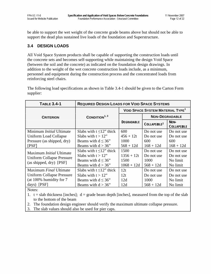
3.5 FORMS AROUND THE TOPS OF THE PIERS
In order to reduce the uplift pressures on pier shafts, the top two-foot portion of each drilled
pier may be formed to the specified shaft diameter. The advantages, disadvantages and
comments of using forms around the tops of piers are shown in Table 3.5-1, below.
TABLE 3.5-1 FORMS AROUND THE TOPS OF THE PIERS ADVANTAGES DISADVANTAGES COMMENTS
1. By eliminating the flair at
the top of the pier, the
contact area between the
soils and the pier will be
reduced, thereby reducing
potential uplift pressures.
2. By eliminating the flair at
the top of the pier,
concrete waste is
eliminated.
1. Additional cost of materials.
2. Additional labor to install.
1. If pier-top forms are not
specified, then the uplift
pressures on the flair should
be accounted for in the uplift
design calculations.
2. Available in 2-foot long
sections.
3. Forms around the top of piers
are typically used when the
elevation at the top of the pier
is near the ground surface.
Figures showing the application of forms at the top of piers are given below:
Forms around the upper 2 feet of piers eliminate flaring
FPA-SC-11-0 Specification and Application of Void Spaces Below Concrete Foundations 11 November 2007 Issued for Website Publication Foundation Performance Association - Structural Committee Page 14 of 22
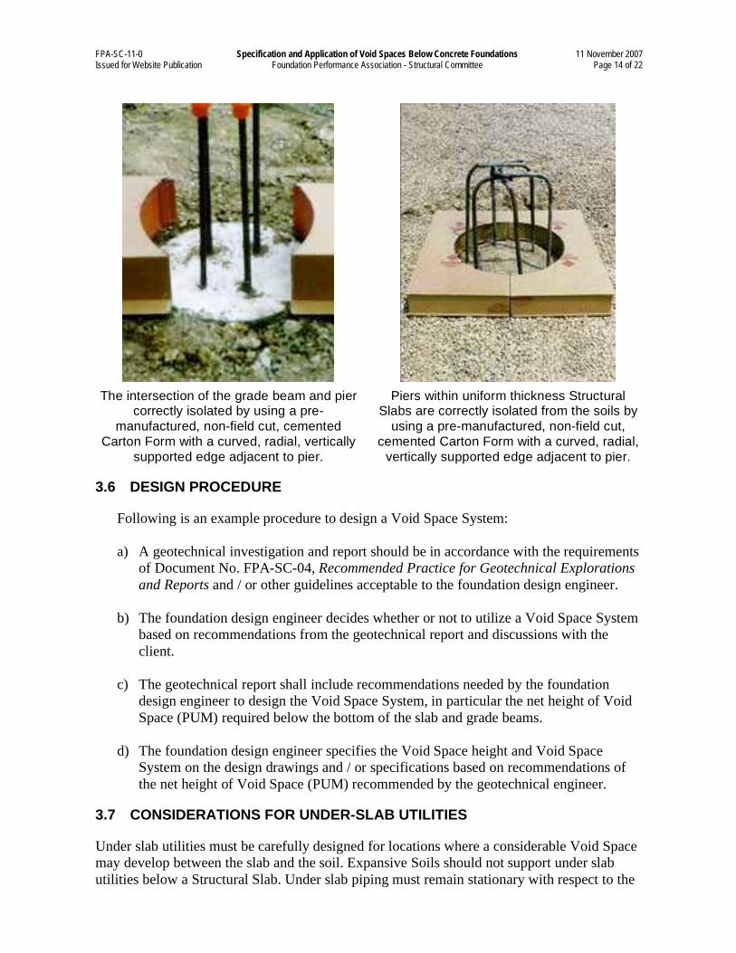
The intersection of the grade beam and pier correctly isolated by using a pre-
manufactured, non-field cut, cemented
Carton Form with a curved, radial, vertically
supported edge adjacent to pier.
Piers within uniform thickness Structural Slabs are correctly isolated from the soils by
using a pre-manufactured, non-field cut,
cemented Carton Form with a curved, radial,
vertically supported edge adjacent to pier.
3.6 DESIGN PROCEDURE
Following is an example procedure to design a Void Space System:
a) A geotechnical investigation and report should be in accordance with the requirements
of Document No. FPA-SC-04, Recommended Practice for Geotechnical Explorations
and Reports and / or other guidelines acceptable to the foundation design engineer.
b) The foundation design engineer decides whether or not to utilize a Void Space System
based on recommendations from the geotechnical report and discussions with the
client.
c) The geotechnical report shall include recommendations needed by the foundation
design engineer to design the Void Space System, in particular the net height of Void
Space (PUM) required below the bottom of the slab and grade beams.
d) The foundation design engineer specifies the Void Space height and Void Space
System on the design drawings and / or specifications based on recommendations of
the net height of Void Space (PUM) recommended by the geotechnical engineer.
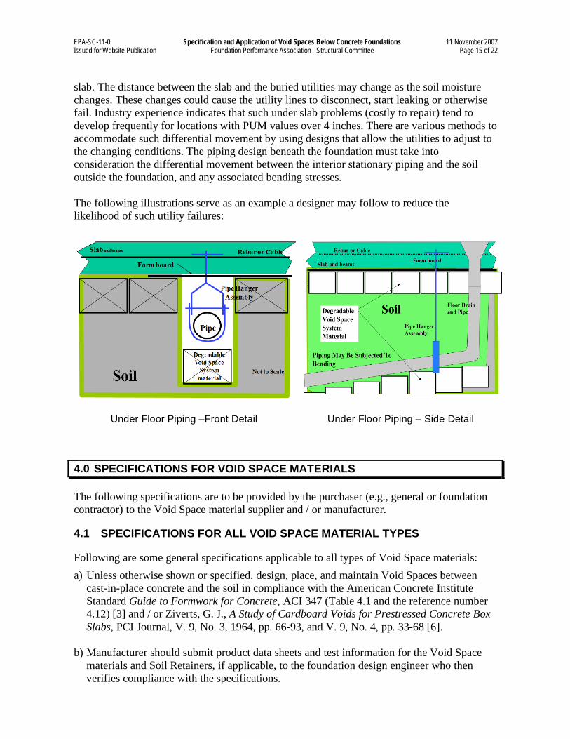
3.7 CONSIDERATIONS FOR UNDER-SLAB UTILITIES
Under slab utilities must be carefully designed for locations where a considerable Void Space
may develop between the slab and the soil. Expansive Soils should not support under slab
utilities below a Structural Slab. Under slab piping must remain stationary with respect to the
FPA-SC-11-0 Specification and Application of Void Spaces Below Concrete Foundations 11 November 2007 Issued for Website Publication Foundation Performance Association - Structural Committee Page 15 of 22
slab. The distance between the slab and the buried utilities may change as the soil moisture
changes. These changes could cause the utility lines to disconnect, start leaking or otherwise
fail. Industry experience indicates that such under slab problems (costly to repair) tend to
develop frequently for locations with PUM values over 4 inches. There are various methods to
accommodate such differential movement by using designs that allow the utilities to adjust to
the changing conditions. The piping design beneath the foundation must take into
consideration the differential movement between the interior stationary piping and the soil
outside the foundation, and any associated bending stresses.
The following illustrations serve as an example a designer may follow to reduce the
likelihood of such utility failures:
Under Floor Piping –Front Detail
Under Floor Piping – Side Detail
4.0 SPECIFICATIONS FOR VOID SPACE MATERIALS
The following specifications are to be provided by the purchaser (e.g., general or foundation
contractor) to the Void Space material supplier and / or manufacturer.
4.1 SPECIFICATIONS FOR ALL VOID SPACE MATERIAL TYPES
Following are some general specifications applicable to all types of Void Space materials:
a) Unless otherwise shown or specified, design, place, and maintain Void Spaces between
cast-in-place concrete and the soil in compliance with the American Concrete Institute
Standard Guide to Formwork for Concrete, ACI 347 (Table 4.1 and the reference number 4.12) [3] and / or Ziverts, G. J., A Study of Cardboard Voids for Prestressed Concrete Box
Slabs, PCI Journal, V. 9, No. 3, 1964, pp. 66-93, and V. 9, No. 4, pp. 33-68 [6].
b) Manufacturer should submit product data sheets and test information for the Void Space
materials and Soil Retainers, if applicable, to the foundation design engineer who then
verifies compliance with the specifications.
FPA-SC-11-0 Specification and Application of Void Spaces Below Concrete Foundations 11 November 2007 Issued for Website Publication Foundation Performance Association - Structural Committee Page 16 of 22
c) Void Space materials shall be designed by the manufacturer to support all vertical and
lateral loads that might be applied until such loads can be supported by the concrete
structure. These loads include, but are not limited to, live load, dead load, weight of
moving equipment, effects of the concrete drop, vibration, and other concrete placement
loads, ambient temperature, and vertical and lateral soil pressures.
d) The contractor shall maintain the Void Space materials prior to concrete placement.
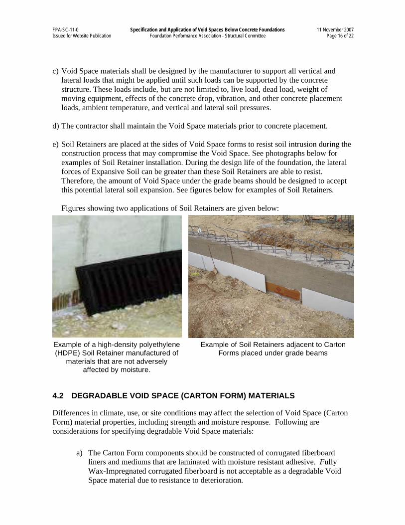
e) Soil Retainers are placed at the sides of Void Space forms to resist soil intrusion during the
construction process that may compromise the Void Space. See photographs below for
examples of Soil Retainer installation. During the design life of the foundation, the lateral
forces of Expansive Soil can be greater than these Soil Retainers are able to resist.
Therefore, the amount of Void Space under the grade beams should be designed to accept
this potential lateral soil expansion. See figures below for examples of Soil Retainers.
Figures showing two applications of Soil Retainers are given below:
Example of a high-density polyethylene
(HDPE) Soil Retainer manufactured of
materials that are not adversely affected by moisture.
Example of Soil Retainers adjacent to Carton
Forms placed under grade beams
4.2 DEGRADABLE VOID SPACE (CARTON FORM) MATERIALS
Differences in climate, use, or site conditions may affect the selection of Void Space (Carton
Form) material properties, including strength and moisture response. Following are
considerations for specifying degradable Void Space materials:
a) The Carton Form components should be constructed of corrugated fiberboard
liners and mediums that are laminated with moisture resistant adhesive. Fully
Wax-Impregnated corrugated fiberboard is not acceptable as a degradable Void
Space material due to resistance to deterioration.
FPA-SC-11-0 Specification and Application of Void Spaces Below Concrete Foundations 11 November 2007 Issued for Website Publication Foundation Performance Association - Structural Committee Page 17 of 22
b) The interior construction of the Void Space material should be of a uniform,
cellular configuration.
c) If the product employs Wax Impregnation, the soil bearing area should not be Wax
Impregnated to ensure that the intended strength loss occurs.
d) Degradable Carton Forms should be the product of a manufacturer engaged in the
commercial production of Carton Forms.
e) Carton Form products may be treated with registered Environmental Protection
Agency (EPA) biocides and fungicides that resist mold, mildew, spore infestation,
and pests.
f) Types of degradable corrugated paper shall be either plain paper, plain paper with
water-resistant adhesive, or Wax Impregnated medium paper as detailed below:
1) Plain Paper has no moisture resistance and is used in low moisture and low
humidity environments. This type of paper employs regular adhesive and no
wax or chemical water repellant. This fully degradable paper is extremely
susceptible to moisture and, once wetted, cannot be used.
2) Plain Paper with Water-resistant Adhesive has some moisture resistance
and is used in low-to-average moisture environments. This type of water-
resistant paper has no wax or chemical water repellant. This fully
biodegradable paper is susceptible to moisture and will maintain its shape
when lightly wetted if there is no imposed load and, once wetted, cannot be
used.
3) Wax Impregnated Medium Paper and Wax Coated Exterior Paper has
some moisture resistance and is used in average-to-moist conditions in areas
with moderate humidity. This corrugated paper medium is Wax Impregnated
and is made with water-resistant adhesive. This partially biodegradable paper
holds its shape when wet, with no imposed load and, this product cannot be
used once wetted.
4.3 COLLAPSIBLE VOIDS (UNDER GRADE BEAMS ONLY)
a) Materials may be comprised of fully Wax Impregnated corrugated paper product,
plastic, or other non-degradable products. The net volume of the collapsed Void Space
should be sufficient to accept the heaving soils. The Void Space materials should
collapse under the combined weight of the foundation and Superstructure above, but
should be sufficiently stiff to withstand the weight of the foundation and associated
construction loads during concrete placement.
b) Collapsible Carton Forms should be the product of a manufacturer engaged in the
commercial production of Carton Forms.
FPA-SC-11-0 Specification and Application of Void Spaces Below Concrete Foundations 11 November 2007 Issued for Website Publication Foundation Performance Association - Structural Committee Page 18 of 22
c) Carton Form products may be treated with registered Environmental Protection
Agency (EPA) biocides and fungicides that resist mold, mildew, spore infestation and
pests.
d) Fully Wax Impregnated corrugated Carton Forms are resistant to deterioration in
strength due to moisture and are not considered to be biodegradable.
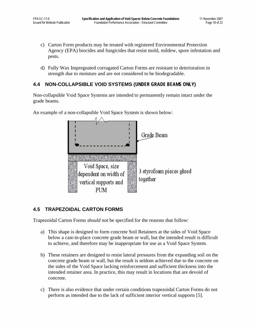
4.4 NON-COLLAPSIBLE VOID SYSTEMS (UNDER GRADE BEAMS ONLY)
Non-collapsible Void Space Systems are intended to permanently remain intact under the
grade beams.
An example of a non-collapsible Void Space System is shown below:
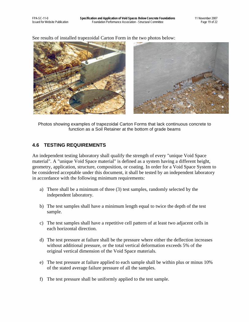
4.5 TRAPEZOIDAL CARTON FORMS
Trapezoidal Carton Forms should not be specified for the reasons that follow:
a) This shape is designed to form concrete Soil Retainers at the sides of Void Space
below a cast-in-place concrete grade beam or wall, but the intended result is difficult
to achieve, and therefore may be inappropriate for use as a Void Space System.
b) These retainers are designed to resist lateral pressures from the expanding soil on the
concrete grade beam or wall, but the result is seldom achieved due to the concrete on
the sides of the Void Space lacking reinforcement and sufficient thickness into the
intended retainer area. In practice, this may result in locations that are devoid of
concrete.
c) There is also evidence that under certain conditions trapezoidal Carton Forms do not
perform as intended due to the lack of sufficient interior vertical supports [5].
FPA-SC-11-0 Specification and Application of Void Spaces Below Concrete Foundations 11 November 2007 Issued for Website Publication Foundation Performance Association - Structural Committee Page 19 of 22
See results of installed trapezoidal Carton Form in the two photos below:
Photos showing examples of trapezoidal Carton Forms that lack continuous concrete to function as a Soil Retainer at the bottom of grade beams
4.6 TESTING REQUIREMENTS
An independent testing laboratory shall qualify the strength of every "unique Void Space
material". A "unique Void Space material" is defined as a system having a different height,
geometry, application, structure, composition, or coating. In order for a Void Space System to
be considered acceptable under this document, it shall be tested by an independent laboratory
in accordance with the following minimum requirements:
a) There shall be a minimum of three (3) test samples, randomly selected by the
independent laboratory.
b) The test samples shall have a minimum length equal to twice the depth of the test
sample.
c) The test samples shall have a repetitive cell pattern of at least two adjacent cells in
each horizontal direction.
d) The test pressure at failure shall be the pressure where either the deflection increases
without additional pressure, or the total vertical deformation exceeds 5% of the
original vertical dimension of the Void Space materials.
e) The test pressure at failure applied to each sample shall be within plus or minus 10%
of the stated average failure pressure of all the samples.
f) The test pressure shall be uniformly applied to the test sample.
FPA-SC-11-0 Specification and Application of Void Spaces Below Concrete Foundations 11 November 2007 Issued for Website Publication Foundation Performance Association - Structural Committee Page 20 of 22
4.7 SUBMITTALS
As a minimum for each Void Space System being supplied, the following shall be provided to
the foundation design engineer for review:
a) Product data sheets describing properties such as, but not limited to, geometry,
dimensions, materials, coatings, and test results.
b) If requested, certified laboratory test data.
5.0 HANDLING AND INSTALLATION OF VOID SPACE SYSTEMS
This section provides considerations for onsite protection, quality control, and installation
concerns of Void Space Systems.
5.1 ONSITE VOID SPACE SYSTEMS PROTECTION
Following are recommendations for proper onsite protection of Void Space materials to help
ensure performance as designed:
a) Store Void Space materials in accordance with manufacturer's recommendations.
b) Store degradable Void Space Systems and accessories on an elevated area, not directly
in contact with the ground.
c) Onsite Void Space System materials shall be protected against the elements as
applicable and other means of damage prior to installation, preferably in an enclosed
transport trailer or other storage container.
d) Do not install or use water sensitive Void Space materials that have been damaged.
5.2 INSTALLATION
Care should be given during the installation of the Void Space material in order to ensure that
it is installed according to the manufacturer’s recommendations. Below are some specific
guidelines:
a) Assemble knockdown (unassembled) products as recommended by the manufacturer
to develop designed strengths.
b) Degradable Carton Forms should have access to moisture in order to properly
deteriorate. The degradable Carton Forms should not be wrapped in polyethylene. In
addition, a moisture retarder (polyethylene) should not be used below degradable
Carton Forms because this may not allow deterioration from the subgrade below.
FPA-SC-11-0 Specification and Application of Void Spaces Below Concrete Foundations 11 November 2007 Issued for Website Publication Foundation Performance Association - Structural Committee Page 21 of 22
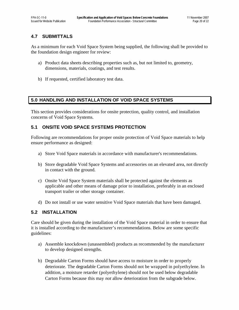
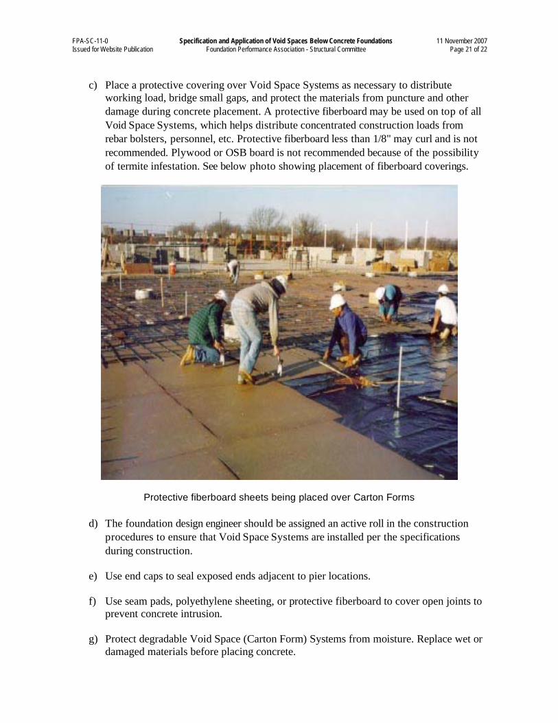
c) Place a protective covering over Void Space Systems as necessary to distribute
working load, bridge small gaps, and protect the materials from puncture and other
damage during concrete placement. A protective fiberboard may be used on top of all
Void Space Systems, which helps distribute concentrated construction loads from
rebar bolsters, personnel, etc. Protective fiberboard less than 1/8" may curl and is not
recommended. Plywood or OSB board is not recommended because of the possibility
of termite infestation. See below photo showing placement of fiberboard coverings.
Protective fiberboard sheets being placed over Carton Forms
d) The foundation design engineer should be assigned an active roll in the construction
procedures to ensure that Void Space Systems are installed per the specifications
during construction.
e) Use end caps to seal exposed ends adjacent to pier locations.
f) Use seam pads, polyethylene sheeting, or protective fiberboard to cover open joints to
prevent concrete intrusion.
g) Protect degradable Void Space (Carton Form) Systems from moisture. Replace wet or
damaged materials before placing concrete.
FPA-SC-11-0 Specification and Application of Void Spaces Below Concrete Foundations 11 November 2007 Issued for Website Publication Foundation Performance Association - Structural Committee Page 22 of 22
h) Ensure that there is positive drainage away from the foundation.
i) Void Space Systems should be properly placed and anchored to prevent displacement
or flotation during placement of concrete.
j) It is acceptable to place moisture retarder over the top of the Carton Forms.
Collapsible Void Systems may be wrapped with a moisture retarder as long as the
entrapped air has a method of escaping prior to concrete placement.
k) Following are installation comments and concerns of Void Space Systems:
• Selection of paper type
• Void Space System minimum and maximum strength (psf)
• Pre-manufactured Void Space System eliminates field cutting
• Fiberboard protection for Void Space System
• Minimize openings to prevent concrete from flowing into Void Space System
• Concentrated loads on Void Space Systems such as from rebar chairs
• Moisture retarder in wrong location
• Onsite weather protection
• Size of concrete pour
• Labor force (size and skill level)
• Weather conditions
• Insufficient soil moisture for degradable Void Space System
6.0 REFERENCES
1. 2006 International Building Code, International Code Council
2. 2006 International Residential Code, International Code Council
3. American Concrete Institute Standard Guide to Formwork for Concrete, ACI 347 (Table
4.1 and the reference number 4.12)
4. Foundation Performance Association, Document No. FPA-SC-01-0, Foundation Design
Options for Residential and Other Low-Rise Buildings on Expansive Soils, 30 June 2004.
5. Isbell, David K., Performance Of Cardboard Carton Forms, presented to the Foundation
Performance Association on 21 February 2001.
6. Ziverts, G. J., A Study of Cardboard Voids for Prestressed Concrete Box Slabs, PCI
Journal, V. 9, No. 3, 1964, pp. 66-93, and V. 9, No. 4, pp. 33-68
Recommended