Space Communications and Navigation Overview
Badri Younes, Deputy Associate AdministratorScience Subcommittee of the NASA Advisory Committee March 11, 2016

Overview
• SCaN’s Responsibilities
• Operations
• Advanced Communication
• Spectrum
2

SCaN is Responsible for all NASA Space Communications
• Operation, management and development Agency-wide for all NASA space communications capabilities and enabling technology.
• Expand SCaN capabilities to enable and enhance robotic and human exploration.
• Manage spectrum and represent NASA on national and international spectrum management programs.
• Develop space communication standards as well as Positioning, Navigation, and Timing (PNT) policy.
• Represent and negotiate on behalf of NASA on all matters related to space telecommunications in coordination with the appropriate offices and flight mission directorates. 3

Vision (So Far)
• “Shrink” the solar system by connecting the principle investigator more closely to the instrument, the mission controller to the spacecraft, and the astronaut to the audience.
• Improve the mission’s experience and reduce mission burden – the effort and cost required to design and operate spacecraft to receive services from the SCaN Network.
• Reduce network burden – the effort and cost required to design, operate, and sustain the SCaN Network as it provides services to missions with the collateral benefit of increasing funding for C&N technology.
• Apply new and enhanced capabilities of terrestrial telecommunications and navigation to space leveraging other organizations’ investments.
• Enable growth of the domestic commercial space market to provide –and NASA to use – commercial services currently dominated by government capabilities.
• Enable greater international collaboration and lower costs in space by establishing an open architecture with interoperable services that fostecommercial competition and can be adopted by international agencies and as well as NASA.
r
4

OPERATIONS
5

NASA Networks Span the Globe
6

7
Example: Deep Space Network Supported Missions
8
Kepler
Chandra
Spitzer
Voyager
Cassini
Dawn MAVEN
New Horizons
STEREO
MSL
Juno
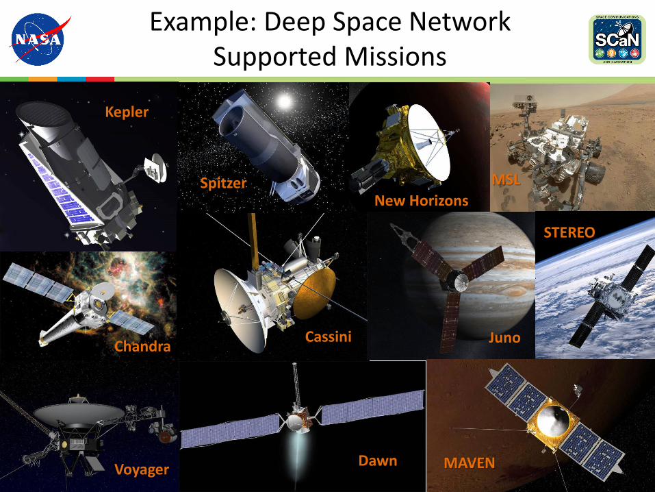
Deep Space Network (DSN)
LOCATION: Tidbinbilla, ~35 km southwest of Canberra, Australia
Managed and operated: Commonwealth Scientific Industrial Research Organization (CSIRO)
Operational Antennas: one 70 m, one 34 m HEF, two 34 m BWG, one 34 m BWG under construction
COMPLEX SIZE: ~0.425 square kilometers
STAFF: ~100
LOCATION: Fort Irwin, ~55 km northeast of Barstow, CA
Operated: Harris Corporation Managed: NASA Jet Propulsion Lab
Operational Antennas:One 70 m, three 34 m BWG, one 34 m HEF, one 34 m HSB, one 34 m R&D antenna, two 34 m educational antennas
COMPLEX SIZE: ~134 square kilometers
STAFF: ~ 165
LOCATION: Robledo de Chavela, ~60 km west of Madrid, Spain
Operated: Ingeniería de Sistemas para la Defensa de España (ISDEFE)Managed: Instituto Nacional de Técnica Aeroespacial (INTA)
Operational Antennas: one 70 m, one 34 m HEF, two 34 m BWG, one 34 m educational antenna
COMPLEX SIZE: ~ 0.490 square kilometers
STAFF: ~ 105
Canberra Goldstone Madrid
99

Deep Space Network (DSN) Facilities
DSS-2534m (BWG-2)
DSS-1534m (HEF)
DSS-2434m (BWG-1)
Goldstone, California
GPS
DSS-2634m (BWG-3)
DSS-1334m (R&D)
DSS-1470m
Signal Processing
Center SPC-10
DSS-5534m (BWG-2)
GPS
Madrid, Spain
DSS-6534m (HEF)
DSS-5434m (BWG-1)
DSS-6370m
Signal Processing
Center SPC-60
DSS-5534m (BWG-2)
DSS-56/5334m (BWG-2)
Canberra, Australia
GPSDSS-45
34m (HEF)
DSS-3434m (BWG-1)
DSS-4370m
Signal Processing
Center SPC-40
DSS-3534m (BWG-2)
DSS-3634m (BWG-2)
CTT-22Compatibility
Test Trailer
JPL, PasadenaDeep Space Operations
Center (DSOC)
MIL-71KSC Launch
Support Facility
JPL, MonroviaNetwork Operations Control
Center (NOCC), DTF-21
10

DSN Aperture Enhancement Project (DAEP) Summary
DSS– 56 (Madrid, Spain)
Under constructionScheduled to be completed i
2019
• The Deep Space Network 70 meter antennas are 50+ years old. Maintenance costs are high and continue to increase.
– These antennas present both physical and technological limitations to potential upgrades needed to support future mission needs.
DSS– 36 (Canberra, Australia) Under construction
Scheduled to be completed in 2016
• New Beam Waveguide (BWG) antenna systems will feature higher reliability, enhanced performance, reduced operations and maintenance costs
DSS– 35 (Canberra, Australia)
Operational: 1 October 2014
DSS-35 CDSCC October 2014 Operational
DSS-36 CDSCC October 2016 Under construction
DSS-56 MDSCC October 2019 Facility work started
DSSS-53 MDSCC October 2020
DSS-33 CDSCC October 2022
DSS-23 GDSCC October 202411
n

Follow the Sun
• Moving from three sites at 24x7 to three sites at 9x7 under follow-the-sun operations supported during day-shifts rotating around each deep space communication complex.
12

Example: Near Earth NetworkSupported Missions
13
Van Allen Probes
RHESSI
Solar-B
QuikSat
SORCE
ICESat
SCISat
Aura EO-1
GRACE
SMAP
IRIS

Near Earth Network (NEN)
NASA Stations• Alaska Satellite Facility, Alaska (two 11 meter, one 10 meter antennas)
• McMurdo Grounds Station, Antarctica (one10 meter antenna)
• Wallops Ground Station, Virginia (one 5 meter, one 11 meter antennas)
• White Sands Complex, New Mexico (one 18 meter antenna)
Commercial• Dongara, Australia (Universal Space Network) (one 13 meter antenna)
• Hartebeesthoek, Africa (Satellite Application Center) (one 18 meter antenna)
• Kiruna, Sweden (Swedish Space Corporation – SSC) (two 13 meter antennas)
• North Pole, Alaska (Universal Space Network) (four antennas – 5.4, 7.3, 11, and 13 meter)
• Santiago, Chile (Swedish Space Corporation – SSC) (one 12 meter, one 13 meter antennas)
• Singapore, Malaysia (Kongsberg Satellite Services – KSAT) (one 9 meter antenna)
• South Point, Hawaii (Universal Space Network) (two 13 meter antennas)
• Svalbard, Norway (Kongsberg Satellite Services – KSAT) (two 11 meter, one 13 meter antennas)
• TrollSat, Antarctica (Kongsberg Satellite Services – KSAT) (one 7.3 meter antenna)
• Weilheim, Germany (Universal Space Network) (two 15 meter antennas)
Partner• Gilmore Creek, Alaska ( National Oceanic and Atmospheric Administration – NOAA) (three 13 meter
antennas)
14

Near Earth Network Upgrades
11 meter AS3 antenna installed in Fairbanks, AK at the Alaska Satellite Facility
• Alaska– For over 20 years, the ground station at
the Alaska Satellite Facility (ASF) has been providing launch, early-orbit, and on-orbit operations to Earth missions utilizing polar orbits.
– Mission requirements and technology has changed and more sophisticated equipment is needed.
– New antenna with an S- and X-band system with Ka-band upgrade capability was added in
• Florida– New antennas are under construction in
order to support launch and early orbit support for future human missions.
15

Example: Space NetworkSupported Missions
16
GPM
Aqua
LandSat-8
OCO-2
Suomi NPP
Hubble Space Station
Fermi
NuSTAR

Space Network (SN) Ground Segment
White Sands ComplexLocation: White Sands, NMOperated by: Harris Corporation
17
Antennas: three 19 meter, two 10 meter, five 4.5 meter, two 1 meter, three 18.3 meter
Guam Remote Station Location: Guam IslandOperated by: Harris Corporation Antennas: one 11 meter, two 16.5 meter, one 4.5 meter, one 5 meter; backup inDongara, Australia – one 11 meter
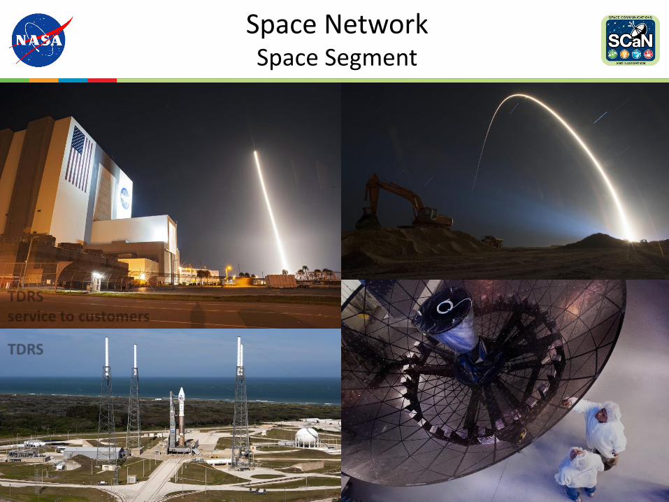
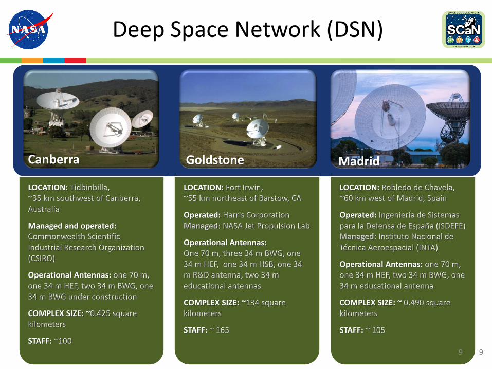
Space NetworkSpace Segment
TDRS-K operational August 2014 and providing service to customers
TDRS-K
TDRS-L operational in February 2015 and providing service to customers
TDRS-L
TDRS-M was completed Summer 2015 and is now in ground storage. Launch planned for mid 2017.
1818

ADVANCED COMMUNICATIONS
19

SCaN’s Future Advanced Communications Capabilities
20

Laser Communications – Higher Performance AND Increased Efficiency
0
20
Giant Leap in Data Rate Performance for less Mass and Power
40
60
0
100
200
300
400
500
600
700
140 130 120 110 100 90 80 70 60 50 40
Data
Rate
LADEE"Dial up"
LRO"Wireless"
30
•
•
•
Lasercomm "Broadband"
Power (W)
Mass (kg)
(Mb
ps)
A
LLCD used:Half the mass25% less powerWhile sending 6x moredata than radio…
21

Laser Communication Relay Demonstration (LCRD) Mission for 2019
• Joint Space Technology Mission Directorate/SCaN Mission
• Commercial spacecraft host
• Two to five years of mission operations
• Flight Payload
– Two LLCD-heritage Optical Modules and Controller Electronics Modules
– Two Differential Phase Shift Keying (DPSK) Modems with 2.88 Gbps data rate
– New High Speed Electronics to interconn ecthe two terminals
– RFI for “Guest Investigators” revealed significant commercial interest
• Key for Next-Gen TDRS (or equivalent) in 20 24timeframe
t
22

FUTURE ARCHITECTURE
23

Background for Current Studies
• Series of studies done in 2013-2015 defining future NASA Communications and Navigation (C&N) architecture, ConOps, and capabilities– Space-Based Relay Study (2013) included an industry RFI
• Current effort intended to complete the process well enough to support budget process including next major acquisitions’ justification and cost estimates:– Earth Network: TDRS fleet capacity drops enough to require new capacity
starting in ~2025– Mars Network: In addition to Mars 2022 mission, Mars Network concept must
be planned to meet HEOMD and SMD needs– Optical communication: Transition joint MD investment in optical
communication to Operations
• RFP released to industry for input to ensure thorough assessment of concepts and capabilities before decisions are made– Vision and architecture concepts presented today are work in progress
24

SPECTRUM
25

WRC-15 Overview
• 2015 World Radiocommunication Conference (WRC-15) took place in Geneva, SW, 2-27 November 2015– Over 160 International Telecommunication Union members participated in treaty-based
modifications to the ITU Radio Regulations
• Technical preparatory work done in the ITU Radiocommunication Sector Study Groups
• Conference Preparatory Meeting (CPM) report contained approaches (Methods) for satisfying each agenda item (technical basis upon which Administration proposals are made)
• US Regulators oversee conference preparations by Federal Government (NTIA) and private sector (FCC)
• U.S. Delegation to WRC-15 lead by Ambassador Decker Anstrom26
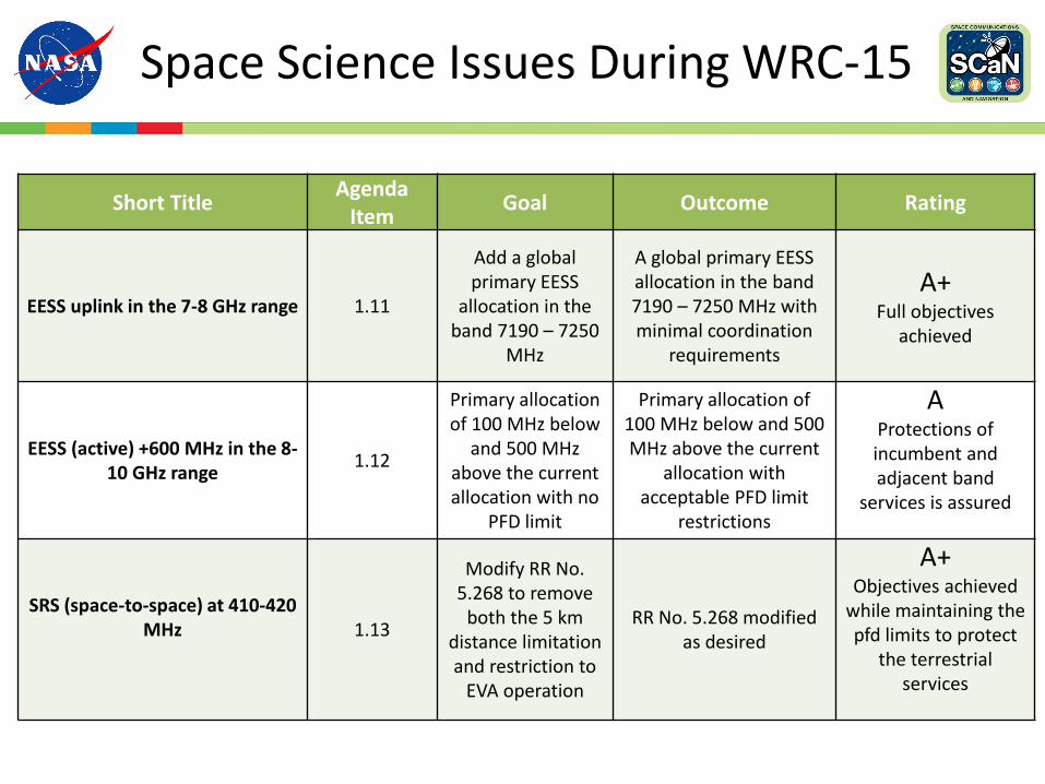
Space Science Issues During WRC-15
Short TitleAgenda
ItemGoal Outcome Rating
EESS uplink in the 7-8 GHz range 1.11
Add a global primary EESS
allocation in the band 7190 – 7250
MHz
A global primary EESS allocation in the band 7190 – 7250 MHz with minimal coordination
requirements
A+Full objectives
achieved
EESS (active) +600 MHz in the 8-10 GHz range
1.12
Primary allocation of 100 MHz below
and 500 MHz above the current allocation with no
PFD limit
Primary allocation of 100 MHz below and 500 MHz above the current
allocation with acceptable PFD limit
restrictions
AProtections of incumbent and adjacent band
services is assured
SRS (space-to-space) at 410-420 MHz 1.13
Modify RR No. 5.268 to remove
both the 5 km distance limitation and restriction to
EVA operation
RR No. 5.268 modified as desired
A+Objectives achieved
while maintaining thepfd limits to protect
the terrestrial services

Summary
• SCaN is upgrading NASA’s space communications infrastructure to maintain its high level of excellence, while increasing demand for the future requirements for high data return.
• SCaN continues to develop and demonstrate leading edge space communications technologies, including optical communication, in order to meet future mission needs.
• NASA’s journey to Mars – both for humans and robotics – relies on these space communications and navigation capabilities.
28

NASA
www.nasa.gov
NASA Space Communications and Navigation
https://www.nasa.gov/scan
Facebook: NASASCaN
Twitter: @NASASCaN
utics and Space Administration
29
National Aerona
Recommended