For the most current Installation Instructions, please visit www.solatube.com/instructions Solatube International, Inc. | 2210 Oak Ridge Way | Vista, CA 92081-8341 | www.solatube.com | T: 888.SOLATUBE
© 2010 Solatube International, Inc. Part No. 951780 v2.1
1
Solatube® Brighten Up® Series Solatube® 160 DS Daylighting System Solatube® 290 DS Daylighting System Installation Instructions
Parts List * Quantity
1 Dome with Raybender® 3000 Technology (1)
a. Shock Inner Dome*†
2 Roof Flashing (pitched or no pitch) (1)
3 Top Tube Assembly including: Dome Ring, Dome Ring Seal, Spectralight® Infinity Top Tube with Angle Adapter.
(1)
4 Spectralight® Infinity 16 in (400 mm) Extension Tube
(2)
5 Bottom Tube Assembly including: Spectralight® Infinity Bottom Tube with Angle Adapter, Ceiling Ring
(1)
6 Effect Lens (1)
7 Diffuser (1)
Seal and Fasteners
a. Dome Ring Screws - #8 X 1 in (25 mm) (5)
8
b. LightTracker™ Reflector (1)
c. Flashing Screws - #10 X 2 in (51 mm) (8)
d. Roof Sealant (1)
e. Expansion Joint Seal (1)
f. Tube Screws - #8 X 3/8 in (10 mm) (10)
g. Foil Tape - 2 in (51 mm) X 18 ft (5.5 m) roll (1)
h. Drywall Screws - #6 X 1 5/8 in (40 mm) (4)
3
Required Tools:
Keyhole Saw
Saber or Reciprocating Saw
Hammer
Flat Bar
Utility Knife
Tape Measure
Caulking Gun
Screw Gun with Phillips Head
Lumber Crayon
Magnetic Compass
Required Safety Equipment
4
5
2
7
6
8f
8d
8b
8e
8a
8c
1a
1
8h
*†High Velocity Hurricane Zones: Shock Inner Dome must be installed with dome. To meet HVHZ requirements, use a six inch no pitch flashing or a pitched flashing with a four inch turret extension.
8g
*Components shown not included in all kits, see label on box.

For the most current Installation Instructions, please visit www.solatube.com/instructions Solatube International, Inc. | 2210 Oak Ridge Way | Vista, CA 92081-8341 | www.solatube.com | T: 888.SOLATUBE
© 2010 Solatube International, Inc. Part No. 951780 v2.1
2
WARNING
Daylighting Systems Installation Tips
These instructions are a step-by-step guide for the installation of a Solatube Daylighting System in the following conditions.
For other roof types, please contact your Solatube International representative for additional information.
Built Up Flat Roof - Single Ply/Membrane - Asphalt Shingle - Low/No Pitched - Pitched - Prefabricated Curbs - Metal Roof Panels
Please refer to the installation tips for the appropriate product below:
Do not proceed with the installation until you have read the entire instructions, including these warnings. (Use of materials or methods not authorized by Solatube International will result in an invalid warranty.)
Solatube International, Inc. (seller) assumes no responsibility or obligation whatsoever for the failure of an architect, contractor, installer, or building owner to comply with all applicable laws, ordinances, building codes, electrical codes, energy codes, fire and safety codes and requirements, roof warranties and adequate safety precautions. Installation of this product should be attempted only by individuals skilled in the use of the tools and equipment necessary for installation. Protect yourself and all persons and property during installation. If you have any doubt concerning your competence or expertise, consult a qualified expert before proceeding.
Install at your own risk! Solatube product installations may be dangerous and include the potential for death, personal injury and property damage. The hazardous conditions include but are not limited to the following:
During installation, the Solatube Daylighting System’s reflective tubes may focus sunlight, causing intense heat or fire. Remove
protective film only after the parts have been installed. Prior to and during installation, do not leave tubes in contact with
combustible materials or unattended, especially near direct sunlight. Avoid skin burns. Solatube Daylighting System and Solar Star products may have sharp edges. Always wear leather or canvas gloves while handling and installing
products. Solatube product installations require climbing and working at dangerous heights, including on ladders, scaffolding, roofs and in attic spaces.
Risk of death, personal injury and property damage may result from a fall, or from falling objects. Use extreme caution to minimize risk of
accidental injury, including, but not limited to the following procedures: Clear area below your work space of all people, animals and other items. Avoid working on surfaces that are slippery or wet. Use foot-wear with excellent traction. Use only strong, well supported ladders. Work only in calm dry weather. When in the attic, ensure that your weight is supported at all times with structurally sound framing; drywall material is not designed to
carry a person’s weight. To reduce the risk of fire, electric shock, and personal injury, basic safety precautions should always be followed when using electric tools,
including always wearing safety goggles or other suitable eye protection, and ensuring work area is clear of all electrical wires, gas pipes, water
pipes, and other obstacles. When working in the attic or other dusty areas, use of a mask or respirator is recommended to avoid lung irritation. Attic spaces may be dark,
confined, and subject to extreme temperatures. Beware of sharp protruding objects. Do not attempt installation without having someone within
range of your voice or close enough to come to your aid if necessary. Solatube products are not designed to withstand the weight of a person, tools or other objects. Walking or placing objects on the system could
cause personal injury and property damage. If the product is damaged, the structural capacity may be weakened; therefore the system should
be repaired immediately. For safe installation and use, do not deviate from these installation instructions.
Electrical Components Before installing, servicing, or cleaning unit, switch power off at service panel and lock service panel to prevent power from becoming switched
on accidentally. When the service disconnecting means cannot be locked, securely fasten a prominent warning device such as a tag to the
service panel.
Re-Roofing Solatube products require special care if removed for re-roofing. In order to ensure proper removal and re-installation, please contact your
Solatube International representative.
For the most current Installation Instructions, please visit www.solatube.com/instructions Solatube International, Inc. | 2210 Oak Ridge Way | Vista, CA 92081-8341 | www.solatube.com | T: 888.SOLATUBE
© 2010 Solatube International, Inc. Part No. 951780 v2.1
3
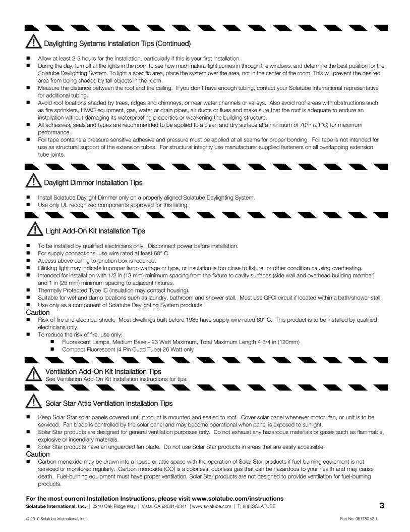
Solar Star Attic Ventilation Installation Tips
Keep Solar Star solar panels covered until product is mounted and sealed to roof. Cover solar panel whenever motor, fan, or unit is to be
serviced. Fan blade is controlled by the solar panel and may become operational when panel is exposed to sunlight. Solar Star products are designed for general ventilation purposes only. Do not exhaust any hazardous materials or gases such as flammable,
explosive or incendiary materials. Solar Star products have an unguarded fan blade. Do not use Solar Star products in areas that are easily accessible.
Caution Carbon monoxide may be drawn into a house or attic space with the operation of Solar Star products if fuel-burning equipment is not
serviced or monitored regularly. Carbon monoxide (CO) is a colorless, odorless gas that can be hazardous to your health and may cause
death. Fuel-burning equipment must have proper ventilation, Solar Star products are not designed to provide ventilation for fuel-burning
products.
Light Add-On Kit Installation Tips
To be installed by qualified electricians only. Disconnect power before installation. For supply connections, use wire rated at least 60° C. Access above ceiling to junction box is required. Blinking light may indicate improper lamp wattage or type, or insulation is too close to fixture, or other condition causing overheating. Intended for installation with 1/2 in (13 mm) minimum spacing from the fixture to cavity surfaces (side wall and overhead building member)
and 1 in (25 mm) minimum spacing to adjacent fixtures. Thermally Protected Type IC (insulation may contact housing). Suitable for wet and damp locations such as laundry, bathroom and shower stall. Must use GFCI circuit if located within a bath/shower stall. Use only as a component of Solatube Daylighting System products.
Caution Risk of fire and electrical shock. Most dwellings built before 1985 have supply wire rated 60° C. This product is to be installed by qualified
electricians only. To reduce the risk of fire, use only:
Fluorescent Lamps, Medium Base - 23 Watt Maximum, Total Maximum Length 4 3/4 in (120mm) Compact Fluorescent (4 Pin Quad Tube) 26 Watt only
Daylighting Systems Installation Tips (Continued)
Allow at least 2-3 hours for the installation, particularly if this is your first installation. During the day, turn off all the lights in the room to see how much natural light comes in through the windows, and determine the best position for the
Solatube Daylighting System. To light a specific area, place the system over the area, not in the center of the room. This will prevent the desired
area from being shaded by tall objects in the room. Measure the distance between the roof and the ceiling. If you don’t have enough tubing, contact your Solatube International representative
for additional tubing. Avoid roof locations shaded by trees, ridges and chimneys, or near water channels or valleys. Also avoid roof areas with obstructions such
as fire sprinklers, HVAC equipment, gas, water or drain pipes, air ducts or flues and make sure that the roof is adequate to endure an
installation without damaging its waterproofing properties or weakening the building structure. All adhesives, seals and tapes are recommended to be applied to a clean and dry surface at a minimum of 70°F (21°C) for maximum
performance. Foil tape contains a pressure sensitive adhesive and pressure must be applied at all seams for proper bonding. Foil tape is not intended for
use as structural support of the extension tubes. For structural integrity use manufacturer supplied fasteners on all overlapping extension
tube joints.
Daylight Dimmer Installation Tips
Install Solatube Daylight Dimmer only on a properly aligned Solatube Daylighting System. Use only UL recognized components approved for this listing.
Ventilation Add-On Kit Installation Tips See Ventilation Add-On Kit installation instructions for tips.

For the most current Installation Instructions, please visit www.solatube.com/instructions Solatube International, Inc. | 2210 Oak Ridge Way | Vista, CA 92081-8341 | www.solatube.com | T: 888.SOLATUBE
© 2010 Solatube International, Inc. Part No. 951780 v2.1
4
1/2 in (12.7 mm)
Roof Underlayment
4 Remove Roof Shingles
Center on Nail and Trace Inside Flashing Base
Roof Underlayment
5
Mark Ceiling and Roof Location Between Joists and Rafters Using Nails. Cut Ceiling Hole. Minimum clearance of 5 3/8 in (140 mm) for 160 DS and 7 3/8 in (190 mm) for 290 DS between nail hole center and joist.
2
1
3 Cut Roof Opening
Set Flashing
Nail
Nail
Nail
Cut Line; 1/2 in (13 mm) Outside Traced Line
Traced Line
a c
b
b
160 DS Ø 10 3/4 in (275 mm)
290 DS Ø 14 3/4 in (375 mm)
Ceiling
Roof
a
Roof Sealant (3/8 in (10 mm) thick)
160 DS 5 3/8 in (140 mm)
290 DS 5 3/8 in (190 mm)

For the most current Installation Instructions, please visit www.solatube.com/instructions Solatube International, Inc. | 2210 Oak Ridge Way | Vista, CA 92081-8341 | www.solatube.com | T: 888.SOLATUBE
© 2010 Solatube International, Inc. Part No. 951780 v2.1
5
7 Align Dome Ring and Flashing Holes
8 Align Top Tube Angle with Ceiling Opening
9 Remove and Tape Top Tube Tape all seams.
6 Fasten Flashing to Roof and Replace Shingles
Roof Underlayment
10 Fasten Top Tube to Flashing*
*For HVHZ dip screw threads in sealant
11 Dome Installation Reflective side of LightTracker™ Reflector faces South in Northern Hemisphere (North in Southern Hemisphere). Align and snap dome into place engaging all four snaps.
Shock Inner Dome for HVHZ
LightTracker™ Reflector
Flashing Screw
Dome Ring Screw
a
b
c
a
b
Remove Protective Liner
Remove Protective Liner
b
a

For the most current Installation Instructions, please visit www.solatube.com/instructions Solatube International, Inc. | 2210 Oak Ridge Way | Vista, CA 92081-8341 | www.solatube.com | T: 888.SOLATUBE
© 2010 Solatube International, Inc. Part No. 951780 v2.1
6
Insert bottom tube assembly into top tube; do not tape seam.*
Apply pressure to tape for proper bonding
Minimum Overlap at Tube Seams 1 1/2 in (38 mm)
c d
h Foil Tape
Assemble and Install Tube Run Use notches to create a tapered tube.
12 Insert Bottom Tube Align and measure tube run.
Minimum Overlap at Tube Seams 1 1/2 in (38 mm)
Minimum Overlap at Tube Seams 1 1/2 in (38 mm)
Tube length measurements should be equal.
Tube Screw Expansion Joint Seal
a
b
e f
g
a
b
*Tape seam for commercial install with suspended ceiling.
Remove Protective Liner
13
For the most current Installation Instructions, please visit www.solatube.com/instructions Solatube International, Inc. | 2210 Oak Ridge Way | Vista, CA 92081-8341 | www.solatube.com | T: 888.SOLATUBE
© 2010 Solatube International, Inc. Part No. 951780 v2.1
7
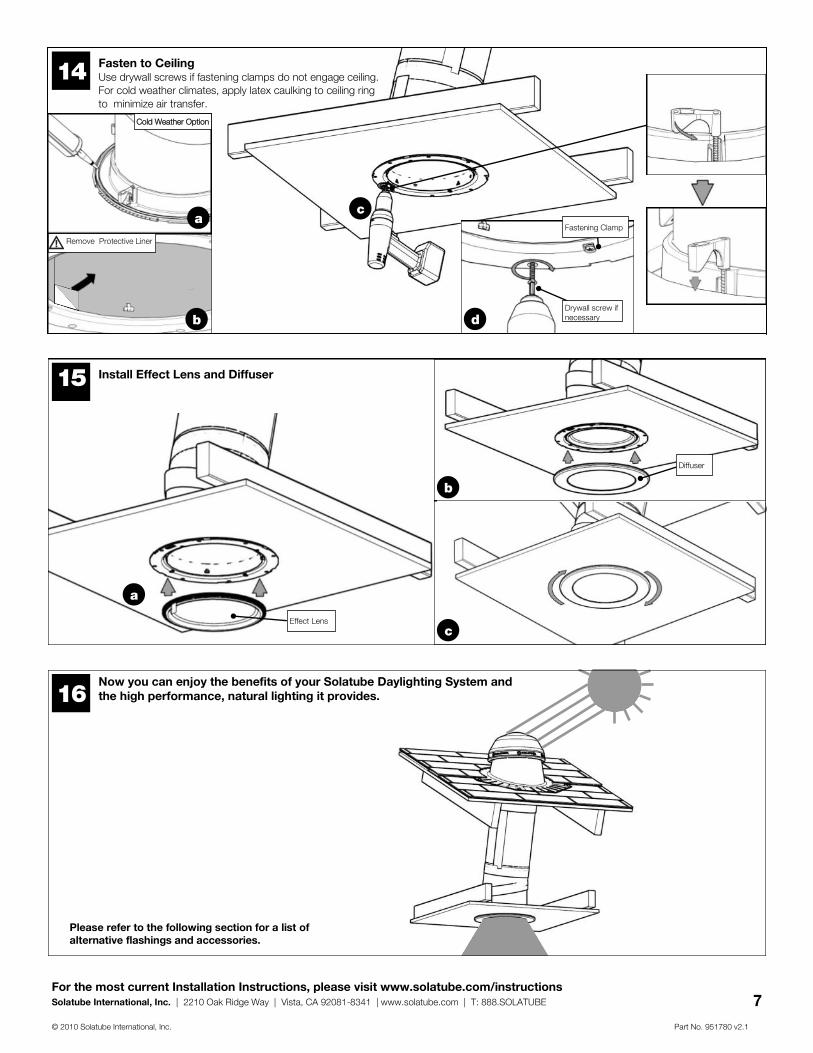
Fasten to Ceiling Use drywall screws if fastening clamps do not engage ceiling. For cold weather climates, apply latex caulking to ceiling ring
to minimize air transfer.
15 Install Effect Lens and Diffuser
14
Drywall screw if necessary
Fastening Clamp
Cold Weather Option
Now you can enjoy the benefits of your Solatube Daylighting System and the high performance, natural lighting it provides. 16
a c
b d
a
b
c
Remove Protective Liner
Effect Lens
Diffuser
Please refer to the following section for a list of alternative flashings and accessories.

For the most current Installation Instructions, please visit www.solatube.com/instructions Solatube International, Inc. | 2210 Oak Ridge Way | Vista, CA 92081-8341 | www.solatube.com | T: 888.SOLATUBE
© 2010 Solatube International, Inc. Part No. 951780 v2.1
8
Curb by Others (allow for counter flashing roofing material)
1 Apply Sealant to Curb
2 Install Cap on Curb
a
3 Fasten Flashing to Curb
*For HVHZ apply 4 more screws to curb cap.
b
Curb Mounted Flashing Installation Instructions Appendix
Parts List Quantity
1 290 DS (14 in/350 mm) Curb Mounted Flashing (Inside Dimension 27 in (685 mm) X 27 in (685 mm))
(1)
Additional Materials and Tools Quantity
1 Roof Sealant (1)
2 Flashing Screws #10 X 2 in (50 mm) (8)
27 in (685 mm) inside dimension
27 in (685 mm) inside dimension
Flashing Screw

For the most current Installation Instructions, please visit www.solatube.com/instructions Solatube International, Inc. | 2210 Oak Ridge Way | Vista, CA 92081-8341 | www.solatube.com | T: 888.SOLATUBE
© 2010 Solatube International, Inc. Part No. 951780 v2.1
9
3 Set Base Flashing
a
Roof Sealant (3/8 in (10 mm) thick)
b
1 Remove Tiles. Center on Nail and Trace Inside Flashing Base.
Nail
2
Traced Line
Nail
Cut Line; 1/2 in (13 mm) Outside Traced Line
4 Fasten Flashing to Roof
b
a
Flashing Screw
Universal Tile Flashing Installation Instructions Appendix
(with Base Flashing)
Parts List Quantity
1 Tile Flashing (Pitched or No Pitch version) (1)
2 Base Flashing (Pitched or No Pitch version) (1)
2 Aluminum “L” bracket (4)
3 #8 X 1/4 in (6 mm) screws (8)
Additional Materials and Tools Quantity
1 Roof Sealant (1)
2 Flashing Screws—#10 X 2 in (50 mm) screws (8)
3 Tile Grinder (1)
Note: These instructions are for non-HVHZ areas only. Contact a Solatube International representative for recommendations in HVHZ areas.
Caution: The use of Portland Cement based mastic, grout, or alkaline materials will cause damage to the aluminum flashing.
Cut Roof Opening

For the most current Installation Instructions, please visit www.solatube.com/instructions Solatube International, Inc. | 2210 Oak Ridge Way | Vista, CA 92081-8341 | www.solatube.com | T: 888.SOLATUBE
© 2010 Solatube International, Inc. Part No. 951780 v2.1
10
Set Universal Tile Flashing Bend front edge of Universal Tile Flashing to fit shape of roof
tiles.
5
6 Fasten Universal Tile Flashing to Base Flashing
b
Base Flashing
#8 X 1/4 in (6 mm) Screw
Universal Tile Flashing
a
8 Secure Flashing to Tile
c
Flashing Edge
L-bracket
b
a
7 Cut and Replace Roof Tiles
#8 X 1/4 in (6 mm) Screw

For the most current Installation Instructions, please visit www.solatube.com/instructions Solatube International, Inc. | 2210 Oak Ridge Way | Vista, CA 92081-8341 | www.solatube.com | T: 888.SOLATUBE
© 2010 Solatube International, Inc. Part No. 951780 v2.1
11
3 Apply Sealant to Roof and Flashing
Roof Sealant 3/4 in (20 mm) thick
a
Roof Sealant 3/4 in (20 mm) thick
b
4 Set Flashing
2 Cut Roof Opening
Cut Line; 1/2 in (13 mm) Outside Traced Line
Flashing Perimeter
Traced Line
1 Center on Nail. Trace Inside and Outside Flashing Perimeter.
Nail
a
b
Nail
Flat Roof Installation Instructions Appendix
Parts List Quantity
1 Roof Flashing (no pitch) (1)
2 Flashing Screws - #10 X 2 in (51 mm) (8)
Additional Materials and Tools Quantity
1 Straight Edge (1)
2 Roof Sealant (1)

For the most current Installation Instructions, please visit www.solatube.com/instructions Solatube International, Inc. | 2210 Oak Ridge Way | Vista, CA 92081-8341 | www.solatube.com | T: 888.SOLATUBE
© 2010 Solatube International, Inc. Part No. 951780 v2.1
12
5 Fasten Flashing to Roof
a
b
6 Apply Sealant and Spread Evenly Using Straight Edge
a
b
Roof Sealant 3/4 in (20 mm) thick
Straight Edge
a
Turret Extension Installation Instructions Appendix
Parts List Quantity
1 Turret Extension 2 in (50 mm) or 4 in (100 mm) (1)
2 1/4 in (6 mm) screws (4)
Additional Materials and Tools Quantity
1 Roof Sealant (1)
1 Apply Sealant to Flashing and Inside of Turret Extension
a
b
Align Turret Extension with Flashing Holes and Fasten
b c
1/4 in (6 mm)Screw
2
a
Flashing Screw

For the most current Installation Instructions, please visit www.solatube.com/instructions Solatube International, Inc. | 2210 Oak Ridge Way | Vista, CA 92081-8341 | www.solatube.com | T: 888.SOLATUBE
© 2010 Solatube International, Inc. Part No. 951780 v2.1
13
a
b
2 Secure Dome Edge Protection Band With top tube installed, align with dome ring spacers and snap into place.
Dome Edge Protection Band Installation Instructions Appendix
Parts List Quantity
1 Dome Edge Protection Band (1)
Additional Materials and Tools Quantity
1 None
0-90 Degree Extension Tube Installation Instructions Appendix
Parts List Quantity
1 0-90 Degree Extension Tube (1)
2 Tube Screws - #8 X 3/4 in (10 mm) (4)
3 Foil Tape - 2 in (51 mm) X 6 ft (2 m) (4)
Additional Materials and Tools Quantity
1 None
1 Install 0-90 Degree Extension Tube Install only between the top tube and an extension tube or two extension tubes.
c a b
Foil Tape Tube Screw
Apply pressure to tape for proper bonding
Minimum overlap at tube seams 1 1/2 in (38 mm)
Additional structural support may be required for horizontal tube runs. Consult local building code.
Place Dome Edge Protection Band Over Flashing
Bend tabs up prior to installation
a
b
1

For the most current Installation Instructions, please visit www.solatube.com/instructions Solatube International, Inc. | 2210 Oak Ridge Way | Vista, CA 92081-8341 | www.solatube.com | T: 888.SOLATUBE
© 2010 Solatube International, Inc. Part No. 951780 v2.1
14
Solatube Brighten Up® Series Accessories Add more function by upgrading your Solatube Daylighting System with any of these great accessories.
Metal Roof Installation Kit Order this kit for installation of a Solatube 160 DS or 290 DS flashing onto a standing seam metal roof.
Universal Tile Flashing (for applications without base flashing) The Universal Tile Flashing integrates seamlessly with most tile profiles. The malleable flashing skirt, available with a pitched or no pitch turret, easily adapts to the shape of the tile.
Light Add-On Kit When equipped with a light add on kit, the Solatube Daylighting System provides the convenience of a switched light for night time use. Available in an energy efficient compact fluorescent design that meets California Title 24 requirements and in a standard incandescent fixture.
Daylight Dimmer Because you don’t need 100% of the light 100% of the time, the innovative Solatube Daylight Dimmer easily controls the amount of daylight entering a room with the convenience of a switch. Our patented variable butterfly baffle controls the light output.
Ventilation Add-On Kit The Solatube 160 DS is available with an optional Ventilation Add-On Kit. When combined with this innovative accessory, the 2-in-1 ceiling fixture minimizes ceiling penetrations for a more attractive look.
Flashing Insulator This insulating material helps to reduce condensation in cold climates when the flashing is exposed to a humid interior space. The insulator is affixed to the flashing base and the top tube slips through the opening, which provides a seal between the interior and metal flashing.
Dome Upgrade Kit Upgrade an older Solatube product to take advantage of Solatube’s patented Raybender™ 3000 Technology. The dome upgrade kit is installed without removing previous flashing or tubing.
Re-Roofing Recommendations Solatube products require special care if removed for re-roofing. Refer to the Solatube Re-Roofing Recommendations to ensure proper removal and re-installation.
Not all items available for all markets. Contact your Solatube International representative for availability.
Recommended