SmartGateway Framework
by
Shankar Nair
A Thesis Presented in Partial Fulfillment of the Requirements for the Degree
Master of Science
Approved August 2015 by the Graduate Supervisory Committee:
Yann-Hang Lee, Chair
Georgios Fainekos Joohyung Lee
ARIZONA STATE UNIVERSITY
December 2015
i
ABSTRACT
Cisco estimates that by 2020, 50 billion devices will be connected to the Internet. But 99% of the
things today remain isolated and unconnected. Different connectivity protocols, proprietary
access, varied device characteristics, security concerns are the main reasons for that isolated
state. This project aims at designing and building a prototype gateway that exposes a simple and
intuitive HTTP Restful interface to access and manipulate devices and the data that they produce
while addressing most of the issues listed above. Along with manipulating devices, the framework
exposes sensor data in such a way that it can be used to create applications like rules or events
that make the home smarter. It also allows the user to represent high-level knowledge by
aggregating the low-level sensor data. This high-level representation can be considered as a
property of the environment or object rather than the sensor itself which makes interpreting the
values more intuitive and accessible.
ii
TABLE OF CONTENTS
Page
LIST OF FIGURES ......................................................................................................................iii
LIST OF TABLES .......................................................................................................................... iv
CHAPTER
1 INTRODUCTION .....................................................................................................................1
2 MOTIVATION AND RELATED WORK ............................................................................ 2
3 SMARTHOME ONTOLOGY ................................................................................................... 7
4 SMARTGATEWAY ARCHITECTURE ........................................................................... 13
Data Manager ............................................................................................. 14
Device Manager .......................................................................................... 17
a. Adding a New Device to the SmartGateway Framework......... 20
b. The Notification Agent............................................................... 23
Context Manager ........................................................................................ 24
a. Routing DBus Messages........................................................... 24
b. The Device Catalog................................................................... 26
c. The Ontology Manager.............................................................. 27
Rule Manager ............................................................................................. 28
HTTP Rest Server....................................................................................... 32
5 USE CASES.......................................................................................................................... 39
Touch-Buzzer-LED-Event-Ont...................................................................... 39
Thunder Storm Alert...................................................................................... 41
Air Conditioner Power Wastage Control....................................................... 42
Garage Door Control..................................................................................... 44
Different Smarthomes, Same Application...................................................... 46
6 SCALABILITY AND PERFORMANCE.............................................................................. 47
7 CONCLUSION .................................................................................………………………… 58
REFERENCES................................................................................................................................... 59
iii
LIST OF FIGURES
Figure Page
1. Apple HomeKit High Level Overview .................................................................... 3
2. Google Nest High Level Overview ............................................................................. 4
3. SmartHome Devices ............................................................................................ 7
4. SmartHome Locations ......................................................................................... 8
5. SmartHome Physical Phenomena ........................................................................ 9
6. SmartHome Object Properties .............................................................................. 9
7. SmartHome Data Properties .............................................................................. 10
8. "lighting1" Instance Representation .................................................................... 11
9. SmartGateway Architecture................................................................................ 13
10. Data Manager Design ........................................................................................ 15
11. Device Manager Design ..................................................................................... 18
12. Context Manager Design ................................................................................... 26
13. Rule Manager Design ........................................................................................ 29
14. Response Time for Actions ................................................................................ 54
15. Response Time for Ontology Updates ................................................................ 55
16. Response Time for Event-Subscribers ................................................................ 56
iv
LIST OF TABLES
Table Page
1. CPU - 25 Devices with Varying Number of Events .............................................. 48
2. CPU - 25 Devices with Varying Number of Rules ................................................ 48
3. CPU - 25 Devices with Varying Number of Ontology Updates .............................. 48
4. MEM - 25 Devices with Varying Number of Events .............................................. 48
5. MEM - 25 Devices with Varying Number of Rules ............................................... 49
6. MEM - 25 Devices with Varying Number of Ontology Updates ............................. 49
7. CPU - 25 Devices with Varying Number of Events .............................................. 49
8. CPU - 25 Devices with Varying Number of Rules ................................................ 49
9. CPU - 25 Devices with Varying Number of Ontology Updates .............................. 49
10. MEM - 25 Devices with Varying Number of Events .............................................. 50
11. MEM - 25 Devices with Varying Number of Rules ............................................... 50
12. MEM - 25 Devices with Varying Number of Ontology Updates ............................. 50
1
CHAPTER 1
INTRODUCTION
The SmartGateway Framework is a software solution that is meant to be deployed on an
embedded platform. In this case - The Intel Galileo Gen1 Development Board. The framework
allows the user to register devices, make them discoverable, allow remote command executions,
read the sensor data, create rules and events in Prolog syntax using the sensor data, allow data
storage locally in-memory or to the ThingSpeak Cloud platform, get notifications about custom
events over email or subscribe to the Cloud channel. Knowledge about the environment and the
various devices and sensors are handled by the use of an Ontology. This Ontology can be further
updated to represent high-level information from the low-level sensor data using the "rule" facility
provided by this framework.
2
CHAPTER 2
MOTIVATION AND RELATED WORK
The main motivation behind developing this SmartGateway is to expose and represent
devices/sensors and the data produced by them, in a way that makes them easily and intuitively
accessible. For instance, one would want to know the current temperature of the living room. The
way this kind of request is handled currently is by "naming" and "deploying" a temperature sensor
in the living room and then probing this device for its data. This implies that the end user needs to
know the exact unique device instance. The conversion from the high level concept of
"temperature of a location" to "data from sensor X" has to be done by the end user. This problem
is further accentuated when an IoT Application Provider needs to deploy a software agent that
requires data from these sensors. For example, consider an Application Provider (AP) setting up
a simple (possibly trivial today) "rule" that adjusts the air-conditioner levels based on some
threshold temperature level. The AP then needs to communicate with the end-user to know about
the possible temperature sensors deployed in the living room and then based on the sensor-
specific communication protocols, configure the "rule". Here one can observe several undesirable
interactions/actions but the most obvious ones are:
a. Undesirable interaction between AP and end-user to know about device/sensor deployments
b. Having the rule work for the specific type of temperature sensor.
This makes the whole process tedious and complex.
The SmartGateway aims at eliminating the above by leveraging a simple fact - the rule (or
any application provided by the AP) is dependant only on the data produced by the
device/sensors and not on the actual device. In fact the device need not even be real. It may be
another software agent. Basically it just needs to act as a data source for the "requested data".
Therefore, the temperature data could be retrieved from a temperature sensor or from a
smartphone that pulls the temperature from a web-service. The rule would still work the same
without any changes.
3
As such there needs to be semantic link between the devices and their data so that they can
be queried and accessed effectively in a consistent, uniform and intuitive manner. The
SmartGateway satisfies this requirement by using a semantic technology called Ontology.
A similar approach of using an Ontology as the key technology has been adopted in the
works of K. Kotis and A. Katasonov (2013). The authors present the concept of a Smart Entity
and Control Entity that is used for Ontology alignment and match-making. This enables
automation of deployment of IoT applications in heterogeneous consumer environments. But this
work only provides such Ontological tools and does not provide a platform to create IoT
applications like "rules" and "events" and "notifications". The authors have used the W3C
Semantic Sensor Network Ontology (Barnaghi, Compton, Corcho, Castro, Graybeal, Herzog,
Janowicz, Neuhaus, Nikolov, & Page, 2011) which is a domain-independent ontology that
represents sensors, their observations and the environment they are deployed in. But they
identified the lack of high-level abstractions for the IoT entities.
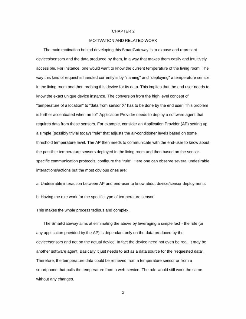
Other works include non-ontological approaches including commercial products like the
Apple HomeKit, Google Nest and Eclipse SmartHome Kit.
Figure 1: Apple HomeKit High Level Overview
4
With Apple’s HomeKit, devices are connected to the home network, and if an Apple TV is
present, paired with that as a “smart-hub”. The phone or tablet (Apple devices only) that are
connected to the same network and those that have the app for the device, can then be paired.
Developers build their apps to connect with the “Home” ecosystem that Apple has built.
Developers need to define a “Home”, along with all its layouts for the devices, locations and
triggers. These attributes then have their defined rules, so that the correct action is triggered on
the right device in the intended location. These triggers need to be delivered exactly as they were
configured. For ex. using the voice command the same command, with the same device name
needs to be used. If the same device is referred to by its location or how it affects the
environment, this command would be resolved. Therefore, device instance resolution is static and
pre-configured. With the Ontology approach this resolution can be done on the basis various
attributes of the device like its location, its data or how it affects the environment.
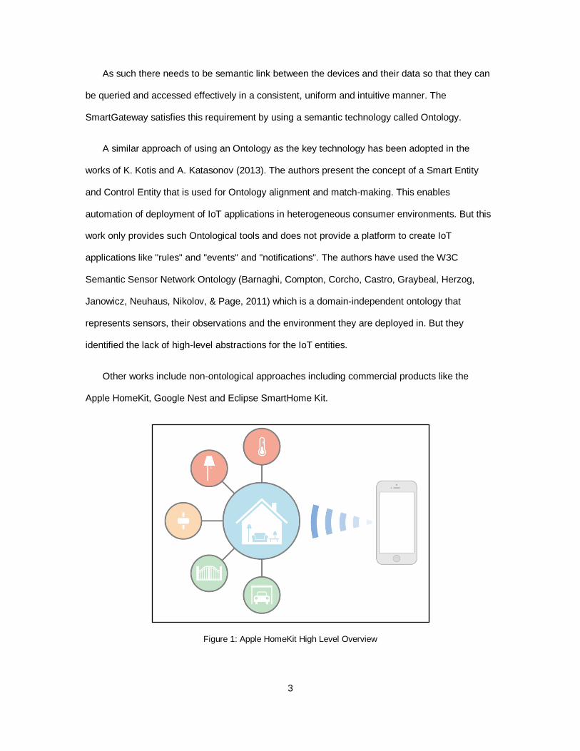
Figure 2: Google Nest High Level Overview
With the Google Nest, users needs to connect their devices via the NEST API after which
third party apps would be able to access and control these devices. Again the discovery of
devices is static and has to be done before hand. Also, since control of the household devices is
now handled by external entities, there is always a problem of privacy and security. With the local
SmartGateway approach the user is in control of what data is published to the cloud and what
stays locally.
5
The Eclipse SmartHome Project pushes for a similar purpose as discussed in this paper. It's
main objective is to uniformly handle heterogeneous IoT devices so that the higher-level
application development can be deployed quickly with minimum configuration issues. It
introduces the concept of "items" that is a virtual layer between the physical world and the
application. It provides 10 to 15 different "items" like Color, Switch, String, DateTime, Dimmer etc.
for devices that support that functionality. These "items" are predefined. A "thing" is an entity that
is valid information source or provides some service and need not be a physical device. This
approach is similar to what this paper contains. A "thing" may provide multiple functionalities and
each of them is a separate "channel". These channels are linked to items and they react to any
events that are sent out on these links. Initialization and discovery of these devices is taken care
by protocols like mDNS, UPnP and Bonjour. Therefore, there is a device registry formed from this
discovery but there is no semantic meaning to their capabilities nor are they associated to their
location or other distinguishing attributes. Therefore, the devices are still at the center of the
framework. This differs from the Ontological approach described in this paper which makes
device reference resolution very rich and flexible.
There is another Eclipse IoT project called Kura that is being distributed currently (Open-
Source). Kura is a framework that basically acts as a proxy between the field devices (like
sensors) and the Data Centers. This proxy has capabilities of transforming and aggregating data
as well. It can be deployed on any Java supported system with OSGi capabilities. It provides an
abstraction over many of the common network and device communication protocols like
Bluetooth, Serial, USB, GPIO, SPI and I2C. Also since it supports OSGi modules, there are
several connectors available that can communicate over REST, CoAP, MQTT etc. This
framework can be run on small boards like the Raspberry Pi, but will not run well on smaller
boards like the Intel Galileo as Java itself is quite heavy for the amount of resources available for
use. Also, this gateway does not capture the background context of the devices and the
environment it is deployed in and hence does not support a query that refers to properties of the
physical phenomena that are being considered. This also makes any application (eg rules ans
events) dependent on the device instance rather than the actual data that the application is
6
interested in. These limitations are eradicated in the framework described in this paper by the use
of Ontologies and a flexible Rule Manager based on Prolog.
The SmartGateway Framework also provides a mechanism to describe "events" and a
Notification Agent that notifies the subscriber of any such event occurrence.
Another unique feature that is missing from already existing projects is extracting high-level
information from the lower level sensor data. For example, let's consider the example of
representing the room temperature level as "high" or "warm" or "cold". This description of the
room temperature although subjective, gets rid of any units of measurement like Celsius or
Fahrenheit and therefore, seems to be more intuitive and useful to the user. Also, the property of
"temperatureLevel" should be associated to the particular room under consideration and not the
temperature sensor. This kind of representation makes the whole query mechanism very intuitive
and accessible. The SmartGateway Framework provides this feature by leveraging the same
"rule" registration mechanism which will be seen later in this paper.
7
CHAPTER 3
SMARTHOME ONTOLOGY
An Ontology is nothing but a description of a domain in terms of its entities, types properties
and relationships among them. In the case of this project the Ontology models the domain of a
Smarthome which basically represents everything from different locations to devices, sensors and
actuators present in the Smarthome.
The following figures depict the structure of the Smarthome Ontology.
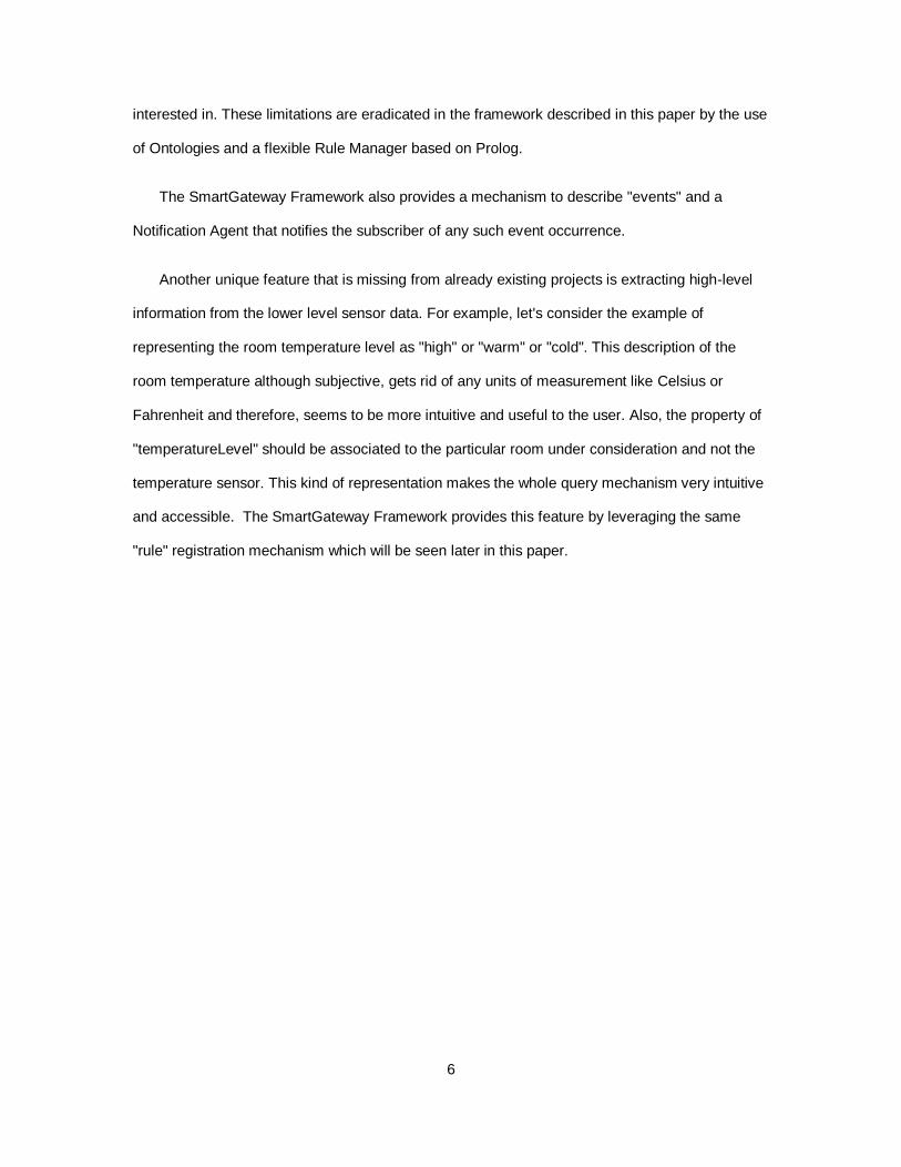
Figure 3: Smarthome Devices
8
Figure 1 shows the representation of a device and the different categories that it contains as
subclasses.
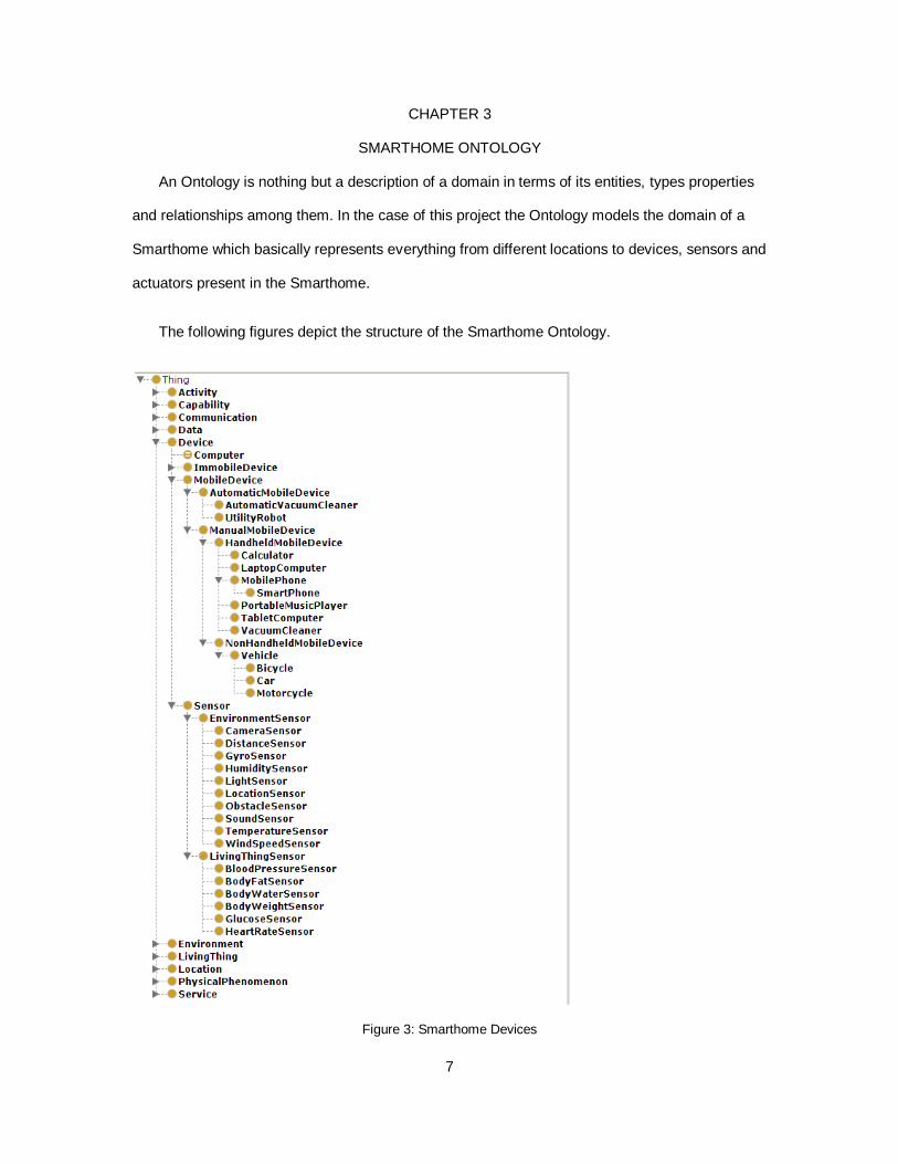
Figure 4: Smarthome Locations
Figure 2 shows the different locations that are typically found in a Smarthome.
9
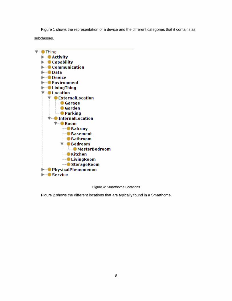
Figure 5: Smarthome Physical Phenomena
Figure 3 shows the different Physical Phenomena or Features of Interest that are caused or
affected or measured by the Devices/Sensors in a Smarthome.
Figure 6: Smarthome Object Properties
10
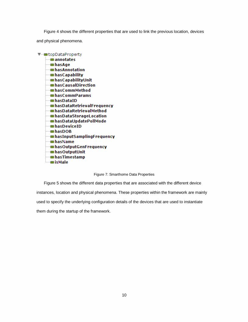
Figure 4 shows the different properties that are used to link the previous location, devices
and physical phenomena.
Figure 7: Smarthome Data Properties
Figure 5 shows the different data properties that are associated with the different device
instances, location and physical phenomena. These properties within the framework are mainly
used to specify the underlying configuration details of the devices that are used to instantiate
them during the startup of the framework.
11
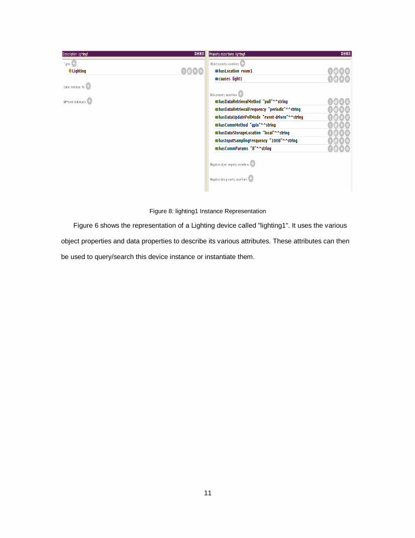
Figure 8: lighting1 Instance Representation
Figure 6 shows the representation of a Lighting device called "lighting1". It uses the various
object properties and data properties to describe its various attributes. These attributes can then
be used to query/search this device instance or instantiate them.
12
CHAPTER 4
SMARTGATEWAY ARCHITECTURE
The SmartGateway framework mainly consists of the following components as separate Linux
processes:
1. DataManager
2. DeviceManager
3. ContextManager
4. RuleManager
5. HTTP RESTful Server
The following section delves into the details of each of these components, describing its
overall conceptual layout and then moving to their interface APIs.
13
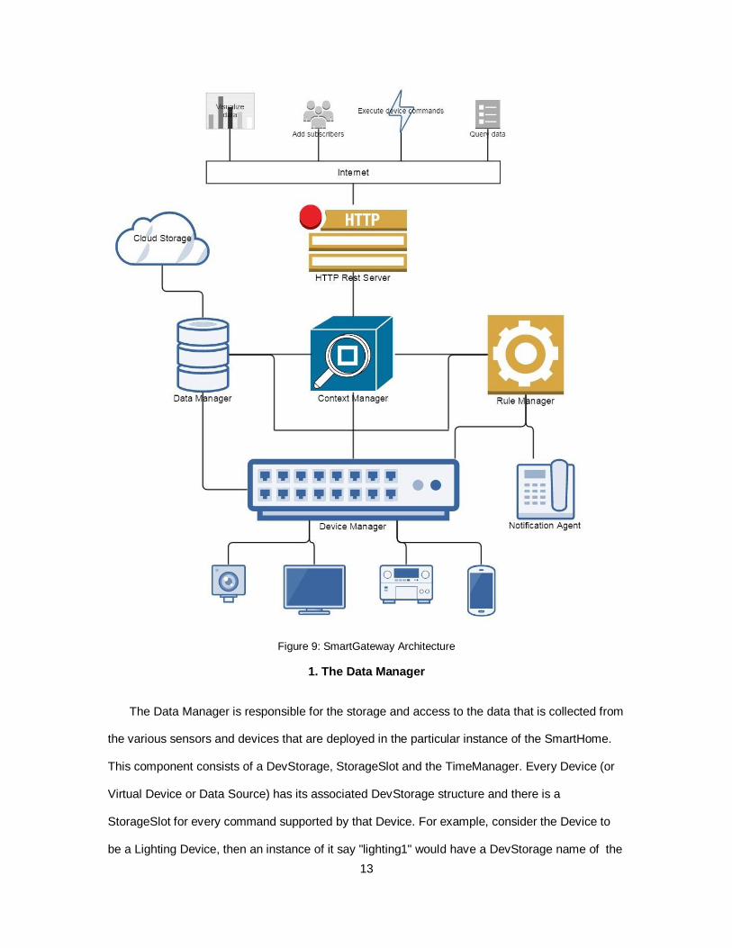
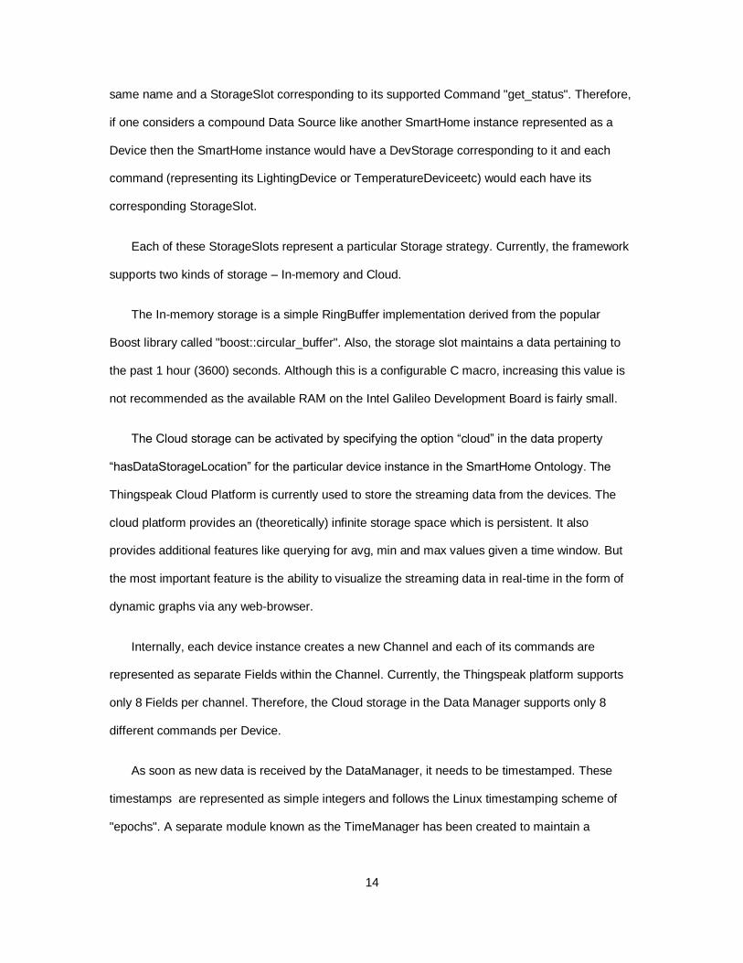
Figure 9: SmartGateway Architecture
1. The Data Manager
The Data Manager is responsible for the storage and access to the data that is collected from
the various sensors and devices that are deployed in the particular instance of the SmartHome.
This component consists of a DevStorage, StorageSlot and the TimeManager. Every Device (or
Virtual Device or Data Source) has its associated DevStorage structure and there is a
StorageSlot for every command supported by that Device. For example, consider the Device to
be a Lighting Device, then an instance of it say "lighting1" would have a DevStorage name of the
14
same name and a StorageSlot corresponding to its supported Command "get_status". Therefore,
if one considers a compound Data Source like another SmartHome instance represented as a
Device then the SmartHome instance would have a DevStorage corresponding to it and each
command (representing its LightingDevice or TemperatureDeviceetc) would each have its
corresponding StorageSlot.
Each of these StorageSlots represent a particular Storage strategy. Currently, the framework
supports two kinds of storage – In-memory and Cloud.
The In-memory storage is a simple RingBuffer implementation derived from the popular
Boost library called "boost::circular_buffer". Also, the storage slot maintains a data pertaining to
the past 1 hour (3600) seconds. Although this is a configurable C macro, increasing this value is
not recommended as the available RAM on the Intel Galileo Development Board is fairly small.
The Cloud storage can be activated by specifying the option “cloud” in the data property
“hasDataStorageLocation” for the particular device instance in the SmartHome Ontology. The
Thingspeak Cloud Platform is currently used to store the streaming data from the devices. The
cloud platform provides an (theoretically) infinite storage space which is persistent. It also
provides additional features like querying for avg, min and max values given a time window. But
the most important feature is the ability to visualize the streaming data in real-time in the form of
dynamic graphs via any web-browser.
Internally, each device instance creates a new Channel and each of its commands are
represented as separate Fields within the Channel. Currently, the Thingspeak platform supports
only 8 Fields per channel. Therefore, the Cloud storage in the Data Manager supports only 8
different commands per Device.
As soon as new data is received by the DataManager, it needs to be timestamped. These
timestamps are represented as simple integers and follows the Linux timestamping scheme of
"epochs". A separate module known as the TimeManager has been created to maintain a
15
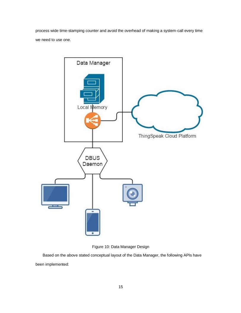
process wide time-stamping counter and avoid the overhead of making a system-call every time
we need to use one.
Figure 10: Data Manager Design
Based on the above stated conceptual layout of the Data Manager, the following APIs have
been implemented:
16
"new" : This command is used to create a new DevStorage compartment within the DataStore.
This is invoked as soon as the Device Manager initializes a new device.
"insert": This command is used to insert new streaming data into the DevStorage. This is invoked
by the Device Manager when it receives new data from any of its sensors/devices for a particular
command. When the data arrives at the DataManager, it is time-stamped and pushed to the In-
memory storage.
"find": This command is used to query the DevStorage for a particular Device with a particular
Command at a particular Timestamp. Currently, the "find" method is used only to fetch the latest
record from a storage slot by passing a 0 as the third input parameter. But this could easily be
extended to return multiple records by passing a non-zero value. Also, it could be extended to
return the MIN, MAX, AVG values. This is already supported by the ThingSpeak Cloud Platform.
2. The Device Manager
The Device Manager is responsible for managing access to the actual physical sensors and
devices. Every device - physical or virtual - is represented as a separate DBus object within this
framework. Therefore, accessing any of the functionality of the these devices means sending
across DBus messages to these objects. Also, any data generated from these devices are
communicated to the other components like the DataManager via DBus messages. A device
could be an actual physical device like a temperature sensor or a table lamp or it could be a
software component - For example the NotificationAgent that we will see later is actually
represented as a device under the Device Manager or it could another compound device
consisting of other smaller devices. For example, we can have another SmartGateway
represented as a device under the Device Manager of another SmartGateway thus allowing a
hierarchical structure of multiple SmartGateways to allow for a wider scope of application.
DBus requires each DBus object to expose an "Interface Definition" XML file. This
requirement very cleanly matches with the representation of a device. As such, every method
defined in the Interface Definition file maps to a specific functionality of the devices. Also, the
17
arguments of these methods correspond to the data required by the devices to implement their
functionality in their lower layer userspace driver architecture. To allow for better device discovery
and functionality resolution, each DBus object has a service name that corresponds to its Class
name in the SmartHome Ontology file. Similarly the Object Path and Interface Path correspond to
their respective components in the Ontology.
Similar to a WSDL file, this Definition file describes the signature of the method to be
remotely executed. The difference is that these methods are not directly exposed to the Internet
and hence do not require the full-blown SOAP support. The Interface Definition File serves this
purpose adequately while allowing for a light-weight implementation.
The use of the SmartHome Ontology in conjunction with the Interface Definition File, makes
querying for devices very flexible as we can now search for devices via SPARQL or DL-query.
This means now we do not need to remember the device instance names to access their
functionality. For example, to turn on a light in the living room, one can query the Ontology file
based on the functionality of "Light" and location as "LivingRoom". This query if successful would
return the exact device instance name that can now be used to access the functionality of turning
on or off the lights. As we will see later, this ability of querying the devices based on their
capabilities and the way they interact and affect the environment are the key features that make
this project unique and more intuitive than existing projects.
The Device Manager architecture heavily relies on the inheritance and virtual function
capabilities provided by C++. On the highest level of abstraction the Device Manager consists of
a DeviceAgent that maintains a map of all the devices that have been instantiated and deployed.
These instantiation requests arrive from the Context Manager as the Context Manager has
access to the Ontology file that contains the details of the layout the specific SmartHome.
18
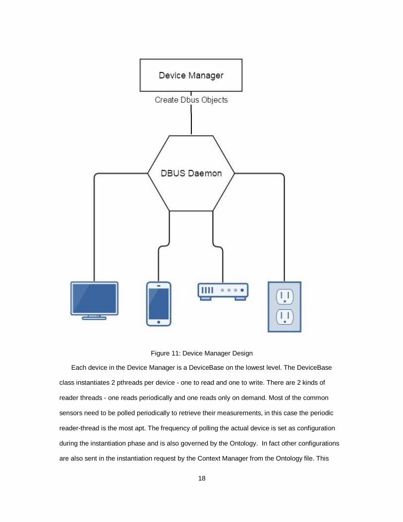
Figure 11: Device Manager Design
Each device in the Device Manager is a DeviceBase on the lowest level. The DeviceBase
class instantiates 2 pthreads per device - one to read and one to write. There are 2 kinds of
reader threads - one reads periodically and one reads only on demand. Most of the common
sensors need to be polled periodically to retrieve their measurements, in this case the periodic
reader-thread is the most apt. The frequency of polling the actual device is set as configuration
during the instantiation phase and is also governed by the Ontology. In fact other configurations
are also sent in the instantiation request by the Context Manager from the Ontology file. This
19
component exposes an API that needs to be overridden by any device driver using this
framework. For example, the API contains OnInit(), which must contain the device initialization of
its handlers or any other initializations, the Write() to populate the driver buffer with the data that
needs to be written and SendToDevice() to handle the actual communication with the device i.e.
sending the contents of the write buffer to the device. A similar strategy is used in case of
Reading from the device. This layer of abstraction also contains the concept of a custom
DeviceHandler. that allows the device driver to communicate using a custom handler. For
example, you can have a INT file descriptor for communication over sockets or file io or it could
be an OpenCV handle to handle communications with the WebCam or other imaging tools.
Once the low level device handling has been taken care, it needs to establish itself as a part
of the whole device network framework. This includes some form of inter-process communication
and signalling on the status changes of the devices or any detected errors. The next layer of
abstraction achieves this by creating a DBus object that is tied to the lower level device handler
for the device. Therefore, any communication with the outside world (i.e the DataManager or the
HTTPRest Server or RuleManager) is handled over DBus.
Every new interface requires its own Dbus Object File. For example, to create a lighting
device of an LED on-board, one would need to first create an Interface Definition File for a
Lighting Device, then inherit that interface using an appropriate name like "ledLightingDevice" and
implement its functions. This "ledLightingDevice" would act as a Driver for "Lighting service via
LEDs".
This implies that a single device could provide multiple services, for example, a Smartphone
would act as a Temperature Sensor or Location Sensor (GPS). In this case, we would need to
define 2 separate Interface Definition Files - one for Temperature Sensor and one for the
Location Sensor. Then we would create 2 separate Driver files - one probably called
SmartphoneTemperatureSensor and the other SmartphoneLocationSensor that inherit and
implement the Temperature and Location Interfaces respectively.
20
Similarly, two different devices could provide the same service. For example, distance
measurements could be provided by the SR-04 distance sensor as well as a WebCam using
OpenCV libraries. Therefore, the Driver files for both these services would inherit from the same
Interface File but their implementations would be different.
a. Adding a New Device to the SmartGateway Framework:
The following steps need to be followed to successfully deploy a new device driver under this
driver framework:
1. Create an Interface Definition XML file that describes the different methods and its arguments
that the device supports. Once such an Interface Definition File has been created, other devices
can reuse the same IDF while providing a different implementation to those interface methods.
2. Use the "dbus-binding-tool" to create the server bindings using the above XML file.
3. Now that the server bindings for the device are ready, you need to write code to make these
bindings accessible through the DeviceManager Framework. Since this code follows a similar
structure as any device, a Code Generator has been written to produce C++ code given the
Interface Definition XML file. To use the Code Generator, place the Interface definition files in the
folder called "input" inside the codegen directory. Now run "./codegen" binary. This will produce
the DBus C object files. Once these are created, you need to create the Interface code files by
referring to any existing code file.
4. Once the DBus objects and the Interfaces have been successfully represented in code, you
need to create the C++ files to override the DeviceBase APIs as described in a previous section.
This completes the representation of a new device in the framework.
5. Now use the API "DEVICE_FACTORY_REGISTER_DEVICE" exposed by the DeviceAgent to
register the newly created device into the framework so that it can be discovered and instantiated.
(The instantiation request comes from the Context Manager using the "new_device" DBus
method call to the DeviceAgent.)
21
The above procedure will register a new device driver into the SmartGateway framework. But
this only describes the way to access and manipulate the device. Now it's Semantic Background
context needs to be specified so that it can become discoverable and query-able by the
framework. This basically means representing the device context in the Ontology.
The following object property assertions need to be made for every device instance:
1. hasLocation: This specifies the location of the device instance in terms of another instantiated
location. For example, lighting1 is a device instance so its "hasLocation" should be something like
"bedroom1" which is an instance of class "Bedroom" subClass of "Room".
2. causes/detects/measures : This property outlines the form of interaction of the device with the
environment and the Physical Phenomena. For example, lighting1 causes light1,
temperatureSensor1 measures temperature1 and touchSensor1 detects touch1.
The following data property assertions need to be made for every device instance:
1. hasCapability: This assertion can be any of "causes" "detects" or "measures" based on the
above object property supported by the device.
2. hasCommMethod: CommMethod denotes the underlying communication method used to talk
to the actual device. Possible options here are: gpio, bluetooth, wifi, tcp, http, custom
3. hasCommParams: The particular comm method will have its own parameters. List them here...
For example,
gpio has the gpio-pin number,
bluetooth has an address,
tcp has an address and port,
http has a server-url,
22
custom is for devices that use some custom abstraction to communication to the actual device.
for example, webCam uses the OpenCV handle.
4. hasDataRetrievalFrequency: Specifies whether data is retrieved from the device "periodically"
or "on-demand". If periodic, we need to check the inputSamplingFrequency to see how frequently
we sample the data from the device. Also, sampling can be done in 2 ways - push or pull as
specified by the dataRetrievalMethod.
5. hasDataRetrievalMethod: Specifies the method used to access the data produced by the
sensor. It can either be "pull" or "push"
"pull": gateway has to query the sensor at "hasOutputGenFrequency" (max).
"push": sensor keeps producing its data at "hasOutputGenFrequency". Gateway keeps accepting.
6. hasDataStorageLocation: The streaming data collected from the devices can be stored either
locally or on the cloud.
Valid options here are "local" or "cloud"
When data is stored locally, a Boost Circular Buffer is used to store data.
When data is stored on the cloud, the Thingspeak platform is used.
7. hasDataUpdatePollMode: This parameter specifies whether the data that is received from the
device either "periodically" or "on-demand" as specified by the dataRetrievalFrequency
parameter, has changed from its previous state.
The valid options for this parameter are - time-driven and event-driven
Time-driven mode is useful for sensors that report some value - int or float, where there is no
particular event that causes the value to change. For example, tempSensor reports the env
temperature. Its value is volatile and changes with respect to time.
23
Event-driven mode is useful for sensors/devices that maintain some finite number of states.
These states change based on some event. For example, a lighting device turns on and off based
on actions executed on it.
Therefore, the event is the action that is executed. Until then the value will not change and
therefore need not be polled.
8. hasInputSamplingFrequency: How often does the sensor receive its input from the
environment. Calculated in milliseconds.
9. hasDriverName: Each Device type has its driver. Therefore, multiple instances of the same
Device Type will use the same driver. The On-board Galileo LED has a GPIO driver called
"ledLightingDevice" that inherits from "LightingDevice". Therefore this assertion would contain the
string "ledLightingDevice"and therefore implements the methods that a Lighting Device should.
(basically from the interface XML file)
b. The Notification Agent
The Notification Agent is a sub-component of the Device Manager that is implemented as a
virtual device within the DeviceManager framework. The main purpose of the Notification Agent is
to provide a Publisher-Subscriber framework where events can be published and interested
subscribers can be notified via their preferred form of communication. Currently, the framework
supports notifications via Email and Cloud.
The typical flow of events when registering a new event is as follows:
The client sends a request to Context Manager via HTTP Post which contains the event
description.
The Context Manager then resolves the device instances via the Ontology and prepares the
Prolog-processible event description.
It then sends the event name to the Notification Agent to create a new event.
24
It sends the Prolog-processible event description to the RuleManager.
When the Notification Agent receives the event description it prepares a subscriber map
especially for this event, so that subscribers can be added for this event later.
Next using the HTTP Restful format, new subscribers are added into the Notification Agent.
It exposes the following functionality via its Interface Definition File:
insert_event: This method is typically used to register a new event, the definition of which is
routed to the RuleManager.
delete_event: This method is used to delete and already existing event description.
add_subscriber: This method is used to add a new subscriber to an already existing event.
We need to pass the necessary description of the subscriber in this request such as the
subscriber name, form of notification (email or cloud) and the email-address or the cloud channel
to upload to.
remove_subscriber: This method is used to remove an already existing subscriber from an
already existing event.
publish_event: This method is used to initiate the notification process to all the subscribers of
the event under consideration.
3. The Context Manager
The Context Manager plays a central role in overall functionality of the SmartGateway
framework. It has 3 important functions:
a. Routing Dbus messages
It basically acts as a router of user request, wherein a request arriving from the HTTP Server
needs to be routed to the right components that can satify that request. This routing decision
varies based on the type of request. The user request typically originates from the HTTP Server.
25
The following are the different types of requests that are possible from the HTTP Server:
1. Device Command: A direct invocation of a functionality of a device specified directly using its
instance name OR an indirect invocation of the functionality of a device specified by its properties
as stated in the Ontology.
2. Request for Ontology Data: The structure of the Ontology can be queried via the HTTP
interface by the Context Manager. For example, a query could be to fetch a device instance name
of type "TempSensor" and that hasLocationLivingRoom. There is another type of data that can be
fetched from the Ontology and that is the Datatype Property that is associated with any of the
Named Individuals or Instances. This comes in handy when querying for data that has been
populated by the "ont" ontology update via the Rule Manager for high-level representations of
low-level sensor data.
3. Request for Device Data: The status/readings of a device/sensor can be queried from the Data
Manager via the Context Manager.
4. Rule Handling: The Context Manager firstly resolves all the device references from the rule
definition and then forwards the modified rule to the Rule Manager. It also supports a delete_rule
functionality that is again sent to the Rule Manager. There are 2 types of rules - Device
Command Executions and Ontology updates.
5. Event Handling: The Context Manager resolves the device references from the event
description and then forwards it to the Rule Manager as well as the Notification Agent. A delete
request is handled similarly. To add/remove subscribers, the Context Manager only needs to
inform the Notification Agent.
26
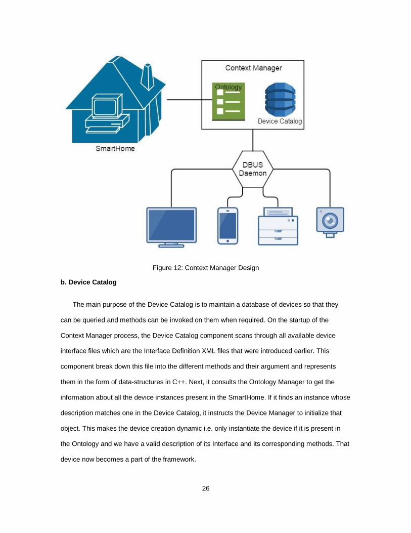
Figure 12: Context Manager Design
b. Device Catalog
The main purpose of the Device Catalog is to maintain a database of devices so that they
can be queried and methods can be invoked on them when required. On the startup of the
Context Manager process, the Device Catalog component scans through all available device
interface files which are the Interface Definition XML files that were introduced earlier. This
component break down this file into the different methods and their argument and represents
them in the form of data-structures in C++. Next, it consults the Ontology Manager to get the
information about all the device instances present in the SmartHome. If it finds an instance whose
description matches one in the Device Catalog, it instructs the Device Manager to initialize that
object. This makes the device creation dynamic i.e. only instantiate the device if it is present in
the Ontology and we have a valid description of its Interface and its corresponding methods. That
device now becomes a part of the framework.
27
c. Ontology Manager
The main purpose of the Ontology Manager is to make data and all its relations accessible to
the framework in a uniform yet flexible manner. On the startup of the Context Manager the
Ontology Manager first loads the SmartHome Ontology file into memory and passes it to the
Factpp reasoning kernel which is part of the OWLCPP library. It mainly exposes 3 important APIs:
1. Fetch Device Instances based on specified properties. For example, Device AND
hasLocationLivingRoom AND measures Temperature should result in something like
"tempSensor1" which is the actual instance that satisfies all the conditions.
2. Fetch data associated with instances. For example, fetch the polling type of a device - event-
driven or time-driven, fetch the read frequency of a sensor, fetch the update frequency of a device
into the Data Manager.
3. Update Ontology with high-level data. For example, set the temperature level of the room as
"cold" based on the reading of the temperature sensor in the room.
The overall purpose of the Context Manager is to maintain background information about the
SmartHome. This background information is represented in terms of an Ontology and Interface
Definition XML and is used effectively to resolve any references to Devices based on their
attributes like Location, Capabilities and how they affect the environment.
The Ontology Manager also exposes an API called "get_device_info" so that components
that require some background context related to the device, can do so. This background context
is usually the device input sampling rate, the poll update mode and the data storage location for
its streaming data.
28
4. Rule Manager
The Rule Manager is the brain of the SmartGateway framework. It instructs the Notification
Agent of an occurrence of an event or that a rule has been satisfied and that an action needs to
be performed as a result of that rule satisfaction. The ability to register rules and events based on
real-time sensor data are the key capabilities that the SmartGateway framework provides. Hence
the Rule Manager needs to access the data produced by the sensors so that it can check for rule
or event satisfactions. But continuously polling for data from devices/sensors may not be a good
idea. This is because of two apparent reasons:
1. The notification may need to be immediate, therefore, having a periodic polling mechanism
means that we will only be notified on the next poll. This introduces a delay in notification which
may not be acceptable for the particular application.
2. The performance of the system is going to be sub-par for polling devices such as switches
which just maintain 2 states - ON or OFF. If these states do change rapidly, it does not make
sense to capture the state every second as it would result in redundant processing. The
framework would benefit from having a event-driven handling of such devices/sensors.
29
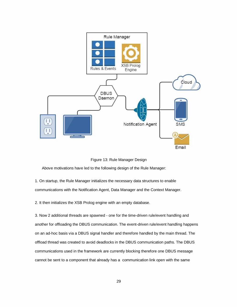
Figure 13: Rule Manager Design
Above motivations have led to the following design of the Rule Manager:
1. On startup, the Rule Manager initializes the necessary data structures to enable
communications with the Notification Agent, Data Manager and the Context Manager.
2. It then initializes the XSB Prolog engine with an empty database.
3. Now 2 additional threads are spawned - one for the time-driven rule/event handling and
another for offloading the DBUS communication. The event-driven rule/event handling happens
on an ad-hoc basis via a DBUS signal handler and therefore handled by the main thread. The
offload thread was created to avoid deadlocks in the DBUS communication paths. The DBUS
communications used in the framework are currently blocking therefore one DBUS message
cannot be sent to a component that already has a communication link open with the same
30
component. This offloading adds an additional advantage of allowing the main thread to return
faster to the user front-end.
4. Every time the Rule Manager receives a new rule, the rule is dissected into different conditions.
The different types of conditions are as follows - "DO", "GET", "EVENT", "ONT" and "GENERAL".
A "DO" condition always appears in the head of a rule. It denotes some action to be performed on
some device. Its format is
do (Dev, Command, Val, Ts)
A "GET" condition always appears in the tail of a rule. It denotes a data-dependency. i.e. It needs
to fetch data from a device/sensor to satisfy the head. Its format is
get (Dev, Command, Val, Ts)
An "EVENT" condition can appear in the head as well as the tail of a rule. When in the head of a
rule it denotes the new occurrence of an event. When in the tail, it expects that the event has
already taken place. Its format is as follows
event (EventName, X, Val, Ts)
Here X means unused. This is done just make the conditions have a similar format.
An "ONT" condition is similar to a "DO" in that they both follow the same Rule processing
path (as opposed to the event processing path). This means that once they are satisfied, the
remainder of the processing is taken care via the Context Manager. But unlike "DO" conditions,
an "ONT" condition can appear in the tail of a rule (like events). Therefore, once the "ONT"
condition is satisfied, it is put nack into the XSB Prolog Knowledgebase.
A "GENERAL" condition can appear only in the tail of a rule. It could be a comparison
condition like "greater than" or "equals to" along with arithmetic expressions as employed in the
standard Prolog syntax.
31
Let's consider an example rule that says "Turn on the lights if the tempSensor reading goes
beyond 100 degrees."
do (lighting1, set_status, 1, Ts) :- get (tempSensor1, get_status, Val, Ts),
get (lighting1, get_status, 0, Ts),
Val > 100.
lighting1 and tempSensor1 are exact instance references that exist in the SmartHome. These are
resolved by the Context Manager by consulting the Ontology.
5. A "GET" condition as we have seen, needs to be resolved by fetching some data from devices.
These are therefore termed as "Data Requestors". A device and one of its command constitute a
unique Data Requestor. The Rule Manager maintains a map of these Data Requestors so that
redundant data lookups can be avoided. For example, there might be multiple rules containing
the same "GET" request, hence the Rule Manager would have to redundantly lookup the same
data.
6. These "GET" conditions are of 2 types - event-driven and time-driven depending on how the
device must be polled for data. In the above example, tempSensor1 is time-driven as its value
changes with time and the lighting1 is event-driven as its state changes are infrequent. This
information is fetched from the Ontology Manager using the "get_device_info" API.
7. Every second the Data Requestor map is checked for any outstanding time-driven "GET"
conditions. If one exists then it is resolved by the DBUS message to the data manager and the
resultant data record is inserted in the XSB Prolog database.
8. After the check for data requestors, the XSB Prolog engine is queried to find any rule/event
satisfactions. These are the queries that are issued...
do (Dev, Command, Val, Ts, RuleId), lastSeenTs(Ts1), Ts> Ts1
ont (Subj, Pred, Val, Ts, RuleId), lastSeenTs(Ts1), Ts> Ts1
32
event (EventName, X, Val, Ts, EventId), lastSeenTs(Ts1), Ts> Ts1
The last argument for the ID is used for fast mapping into the rule map to know which rule
was satisfied.
9. For event-driven devices, once the signal handler is invoked, the data is requested from the
data manager and then inserted into the Prolog database. Now the Prolog query takes place as
mentioned above.
10. Once a rule is satisfied, it can either be re-armed of removed. This is controlled by a
configuration flag called "isOneShot" during rule registration.
11. In case of "rules", once satisfied it is sent to the Context Manager for execution but in case of
"ont" conditions and "events", once satisfied they are put back into the XSB Prolog
Knowledgebase for future rules, events and ontology updates.
12. Once the rule has been satisfied, its previous recorded data is cleaned out from the Prolog
Database so that stale data is not used to satisfy new rules/events. But in case of a recurring rule,
this data cannot be removed and hence a new construct is introduced called "lastSeenTs" that
records the last seen timestamp of the "GET" conditions. Therefore, the query now would only
look at rules and events that have not been seen previously.
5. HTTP Rest Server
The main purpose of the HTTP Server is to provide uniform and easy access to all the
functionality provided by the framework. As such we will first list down the different capabilities of
the framework and explain how they can be accessed via the HTTP Rest Server.
For the sake of explaining the various capabilities of the framework let us consider the
following as a running example for the remainder of the section:
Let's assume the SmartHome consists of one living room of type LivingRoom and one front-
door of type Door - frontDoor1. Now let us also assume that the living room consists of one
33
lighting device of type Lighting - lighting1 and one temperature sensor of type
TemperatureSensor - tempSensor1. Also, the door consists of a gyrosensor of type GyroSensor -
gyroSensor1 that can detect whether the door is opened or not.
On startup, the HTTP Server opens up a listen port on 8080 and then awaits HTTP requests
from the user. The framework can be used for the following functions:
1. Query the framework for structural information about the SmartHome.
The SmartHome Ontology contains the schema or the layout of all the devices and sensors
deployed in and around the home. Their locations and capabilites are descibed as Object
Properties and they are categorized by their Device Class within the Ontology. Hence, these
properties can be used to query for the particular device instance. So in the above example, we
can use the following HTTP GET request format to query the framework.
"http://192.168.0.33:8080/getOntData?Class=Lighting&hasLocation=LivingRoom&Action=instanc
e&causes=Light"
The above request can also be performed using the POST request as follows:
POST url = "http://192.168.0.33:8080/getOntData"
POST payload = "Class=Lighting&hasLocation=LivingRoom&Action=instance&causes=Light"
As we can see the properties except for the "Class" correspond to actual object properties in
the Ontology file and the values like Lighting, LivingRoom and Light are class labels in the
Ontology.
When the above HTTP request is issued on our example SmartHome, it the HTTP Server
forwards it to the Context Manager and the Context Manager resolves the request by replying
with "lighting1" which is the name of the actual device instance in the Ontology.
34
2. Query for high-level knowledge formed by low-level sensor data.
The SmartHome Ontology is updated by the RuleManager whenever its "ont" predicate is
satisfied. This high-level data can be retrieved from the Ontology using the following request
format:
POST url = "http://192.168.0.33:8080/getOntData"
POST payload = <Action=data&Class=bedroom1&Property=hasSoundLevel>
3. Query for data from a device/sensor.
Each Device/Sensor may be a source of one or more types of data. In case of a simple
sensor like the temperature sensor, we obtain floating point values. The sampling frequency in
our framework is a data property of that particular sensor in the Ontology. The device manager
fetches this information from the Context Manager before initializing this sensor within the
SmartGateway. Once it receives a new value from the sensor, periodically or in an event-driven
fashion, it publishes the same to the data manager. Therefore, a request for data from the sensor
can be obtained from the data manager directly once we know which device instance we are
interested in. This device reference is again resolved via the Ontology file in the Context Manager
component.
Hence, we can issue the following HTTP POST request to fetch the data from the
temperature Sensor:
POST url = "http://192.168.0.33:8080/getDevData"
POST payload =
<DevRef=X&Class=Temperature&hasLocation=LivingRoom&measures=Temperature\nDeviceNa
me=<X>&Command=get_status&Ts=0>
The payload consists of two lines seperated by a "\n". The first line describes a device
reference that needs to be resolved via the Ontology (by the Context Manager itself). Once "X"
35
has been resolved, "<X>" is replaced in the second line with that device instance. This modified
command string "DeviceName=tempSensor1&Command=get_status&Ts=0" is sent to the Data
Manager which returns the last "Ts" worth of data values from tempSensor1 and "get_status"
command. If the Ts is 0 then the latest single value is returned.
4. Execute a command on a device.
Along with the Ontology Manager, as seen earlier, the Context Manager also contains a
Device Catalog that maintains a database of all the existing devices and their interfaces including
information about the different methods and their corresponding agruments. The user issues an
HTTP POST request in the following format:
POST url = "http://192.168.0.33:8080/executeCommand"
POST payload =
<DevRef=X&DeviceClass=Device&hasLocation=Bedroom&causes=Light\nDeviceName=<X>&se
t_status=0>
Similar to querying for data from the data manager, here the device reference is first resolved
via the Context Manager and then the modified second command string is sent to the Device
directly as each Device is represented as a DBus Object.
5. Rule-based command execution.
One of the most important capability of the framework is to create custom rules based on the
data collected from the sensors and then perform some action on any devices whenever some
condition is satisfied. Let's consider a simple exampe:
"Turn on the light in the living room if the temperature goes beyond 100 degrees."
The above "application" can be created via one simple HTTP POST request to the
SmartGateway HTTP Rest Server. Here it is...
POST url = "http://192.168.0.33:8080/rule"
36
POST payload =
<DevRef=X&Class=Lighting&hasLocation=LivingRoom&causes=Light\nDevRef=Y&Class=Senso
r&hasLocation=LivingRoom&measures=Temperature\nAction=insert_rule&IsOneShot=true&Rule
=do(<X>, set_status, 0, Ts) :- get(<Y>, get_status, Val, Ts), Val > 100>
The above payload has 2 device references that need to be resolved before the final rule
string can be sent to the Rule Manager. This final rule string is in fact a well-formed Prolog
construct. When the Rule Manager receives a temperature reading greater than 100 degrees it
issues a command to the device via the Context Manager.
6. Ontology Update
Low-level sensor data may not be intuitive enough to the average user. So using the raw
sensor data, properties of Objects within the Ontology can be extrapolated and updated. This
makes interpretation of the sensor data much more accessible and intuitive. This can be achieved
by registering a rule of type "ont". This is done as follows:
POST url = "http://192.168.0.33:8080/rule"
POST payload =
<DevRef=X&Class=Device&hasLocation=Bedroom&measures=Sound\nAction=insert_rule&IsOn
eShot=true&Rule=ont(bedroom1, hasSoundLevel, high, Ts) :- get(<X>, get_status, Val, Ts), Val >
100>
The above request will update the ontology with a new property for the Bedroom called
"hasSoundLevel" and a value "high" whenever the Sound Sensor detects a loud sound in the
room.
This data can be queried from the Ontology as described in point number 2.
37
7. Event detection
Similar to rules, an event is also a well-formed Prolog construct but instead of performing an
action upon satisfaction, it mark the satisfaction as a named-string. This named-string is then
inserted back into the Prolog database so that it can be used to satisfied other Rules or Events.
Along with this, there is also the capability of Subscribing for such Events. For example, we can
create an event called "temperatureExceededThreshold" when the light turns on, in the above
example. The HTTP POST that achieves this is:
POST url = "http://192.168.0.33:8080/event"
POST payload =
<DevRef=X&Class=Lighting&hasLocation=LivingRoom\nAction=insert_event&IsOneShot=false&
EventName=temperatureThresholdExceeded&Event=event(temperatureThresholdExceeded,
event, 0, Ts) :- get(<X>, get_status, X1, Ts1), get(<X>, get_status, X2, Ts) , X1=:=0, X2 =:= 1,
(Ts =:= (Ts1+1))>
Once the device references have been resolved and the light in the living turns on when the
threshold is exceeded, a named-string "temperatureThresholdExceeded" is created and inserted
back into the Prolog database. But it would also be useful to receive some form of notification that
the event did occur. Therefore, the SmartGateway allows adding subscribers to existing Events.
Therefore, assuming the above event has already been inserted into the Rule Manager, we can
add a new subscriber using the following HTTP POST request:
POST url = "http://192.168.0.33:8080/event"
POST payload =
<Action=add_subscriber&EventName=temperatureThresholdExceeded&Name=Shankar&Type=
email&[email protected]>
OR you could upload it to the cloud (currently uses the ThingSpeak platform) using:
38
<Action=add_subscriber&EventName=temperatureThresholdExceeded&Name=Shankar&Type=c
loud&Params=>
Once the event has been satisfied, the Rule Manager instructs the Notification Agent to
publish the event to all its subscribers.
Hence, using the Rule-processing and Event-detection capabilities we were successfully able
to create a notification when the temperature in the Living Room exceeded 100 degrees. This
use-case may not be of any practical use but the same concepts can be effectively employed in a
wide variety of application domains including Electricity Management/Budgeting, Home garden
management right from water management to sunlight and temperature monitoring.
39
CHAPTER 5
USE CASES
We have already seen miniature examples of how the various functionalities of the framework
can be accessed. This section demonstrates a use-case that effectively involves most of these
functionalities which highlights that they are completely compatible with each other and can be
chained together to perform complex functions.
1. Touch-Buzzer-LED-Event-Ont
Let us consider the availability of the following sensors and actuators: light sensor, sound
sensor, touch sensor, buzzer device and an LED device. The scenario is as follows: When the
touch sensor is activated, the buzzer goes off. The sound sensor detects the sound and activates
the LED device. The light sensor detects the LED light and sends an event called "lightOn" to a
subscriber over email and to the ThingSpeak cloud channel. The Ontology is also updated with a
new predicate called "hasLightOn" set to true for the instance of the Bedroom.
The following are the steps one must follow to achieve the above stated application.
1. Populate the Ontology with the details of each of the actuators and sensors. These details are
listed in Chapter 3 Figure 5 and 6.
2. Now create the device driver and interface files as specified in Chapter 4 Subsection "Adding a
New Device to the SmartGateway Framework".
3. Once the binaries have been built, copy them onto the Galileo Board "/root" directory. Also copy
over the Ontology file along with the device interface XML interface definition files into a folder
called "device_interface_files" in the "/root" directory.
4. Follow this sequence to start-up the processes in separate terminals:
a. ./data_manager ==>> Now wait for this process to initialize its local memory and the
ThingSpeak Cloud Storage platform. This takes about 30 seconds.
b. ./device_manager
c. ./context_manager
d. ./rule_manager
40
e. ./http_rest_server 8080
5. Now using any HTTP request generator program like CURL send the following HTTP POST
requests:
a. Touch sensor activates buzzer device
URL: "http://10.218.100.213:8080/rule"
PAYLOAD:
DevRef=X&Class=SoundDevice&hasLocation=Bedroom&causes=Sound\nDevRef=Y&Class=Tou
chDevice&hasLocation=Bedroom&detects=Touch\nAction=insert_rule&IsOneShot=true&Rule=do
(<X>, set_status, 1, Ts) :- get(<Y>, get_status, Val, Ts), Val =:= 1
b. Sound Sensor activates LED device
URL:"http://10.218.100.213:8080/rule"
PAYLOAD:
DevRef=X&Class=SoundSensor&hasLocation=Bedroom&measures=Sound\nDevRef=Y&Class=
Lighting&hasLocation=Bedroom&causes=Touch\nAction=insert_rule&IsOneShot=true&Rule=do(
<X>, set_status, 1, Ts) :- get(<X>, get_status, Val, Ts), Val > 50
c. Light Sensor generates event
URL:"http://10.218.100.213:8080/event"
PAYLOAD:
DevRef=X&Class=LightSensor&hasLocation=Bedroom\nAction=insert_event&IsOneShot=true&E
ventName=lightOn&Event=event(lightOn, event, 1, Ts) :- get(<X>, get_status, Val, Ts1), Val > 30
d. Add Email Subscriber to event
URL:"http://10.218.100.213:8080/event"
PAYLOAD:Action=add_subscriber&EventName=lightOn&Name=Shankar&Type=email&Params=
e. Add Cloud Subscriber to event
URL:"http://10.218.100.213:8080/event"
PAYLOAD:Action=add_subscriber&EventName=lightOn&Name=Shankar&Type=cloud&Params=
f. Event generates Ontology Update for Bedroom with "hasLightOn" set to "yes"
41
URL:"http://10.218.100.213:8080/rule"
PAYLOAD:
Action=insert_rule&IsOneShot=true&Rule=ont(Bedroom, hasLightOn, yes, Ts) :- event(lightOn,
event, 1, Ts)
2. Thunderstorm Alert
This next use-case application allows automatic closing of the window in the bedroom
whenever there is a Thunderstorm alert from the Weather Department. There is also an email
notification sent out regarding the same.
In real life one would need a window and its associated actuator to control the window. To
simplify this requirement, it is assumed that the actuator is a simple switch. A value of 1 means
window is closed and a value of 0 means window is open.
Next create the appropriate device drivers for the actuator above following the guidelines
specified in the previous use-case. Following are the steps required to install the application
correctly:
a. Create device driver
b. Insert Event Definition
POST Url: http://129.219.95.162:8080/event
POST Payload: Action=insert_event_external&EventName=thunderStormAlert
c. Insert Rule Definition
POST Url: http://129.219.95.162:8080/rule
POST Payload:
DefRef=X&Class=Actuator&isAssociatedWith=Window&hasAssociatedLocation=MasterBedroom
&causes=Motion
Action=insert_rule&IsOneShot=false&Rule=do(<X>, set_status, 1, Ts) :-event(thunderStormAlert,
thunderStorm, 1, Ts)
d. Add Email Subscriber
POST Url: http://129.219.95.162:8080/event
42
POST Payload:
Action=add_subscriber&EventName=thunderStormAlert&Name=Shankar&Type=email&Params=
e. Once the ThingSpeak Cloud Platform receives a new value in the ThunderStorm event field, it
needs to trigger a HTTP Post to the SmartGateway Framework. Hence, a ThingHTTP Object is
created with the following parameters:
POST Url: http://129.219.95.162:8080/event
POST Payload: Action=publish_event&EventName=thunderStormAlert&Message=event&Val=1
f. To create the trigger itself use the following parameters in the React App of the Cloud platform:
Test Frequency: On Data Insertion
Condition: SmartHome Events
Field: 1
Action: ThingHTTP
Perform: TriggerThunderStormAlert
Options: Run each time condition is met
Now whenever the Weather Department publishes a Thunder storm alert to the SmartHome
Events field, the window in the Master Bedroom will be automatically closed and an Email
notification would be sent out regarding the same.
3. Air Conditioner Power Wastage Control
This next use-case turns off the air conditioner once it detects that the door in the living room
is open.
This use-case demonstrates the ability to represent high-level knowledge from the low-level
raw sensor data. To create this application we first list out the sensors and actuators that would
be required to successfully deploy this application. Firstly, there is a door in the living room that
has a gyro-sensor attached to it that measures the angular rotation of the door in degrees. Thus
using common-sense knowledge it can be said that the door is in closed position only when the
43
raw reading reads 0 degrees. Any other raw value would imply that the door is open. To model
this common-sense data use the following rule:
POST Url: http://129.219.95.162:8080/rule
POST Payload:
DefRef=X&Class=Sensor&isAssociatedWith=Door&hasAssociatedLocation=LivingRoom&measur
es=Rotation
GenRef=Y&Class=Door&hasLocation=LivingRoom
Action=insert_rule&IsOneShot=false&Rule=ont(<Y>, isOpen, 0, Ts) :-get(<X>, get_status, Val,
Ts), Val =:= 0
POST Url: http://129.219.95.162:8080/rule
POST Payload:
DefRef=X&Class=Sensor&isAssociatedWith=Door&hasAssociatedLocation=LivingRoom&measur
es=Rotation
GenRef=Y&Class=Door&hasLocation=LivingRoom
Action=insert_rule&IsOneShot=false&Rule=ont(<Y>, isOpen, 1, Ts) :-get(<X>, get_status, Val,
Ts), Val > 0
Now one can easily use the high-level knowledge to model any kind of application. To model
turning off the Air Conditioner if Door is open, input the following rule:
POST Url: http://129.219.95.162:8080/rule
DefRef=X&Class=Actuator&hasLocation=LivingRoom&causes=Temperature
GenRef=Y&Class=Door&hasLocation=LivingRoom
Action=insert_rule&IsOneShot=false&Rule=do(<X>, set_status, 1, Ts) :- ont(<Y>, isOpen, 1, Ts)
A point to note is that once such a high-level representation has been created, it can be used
effectively in other applications.
44
4. Garage Door Control
The garage door is usually manually operated during leaving and entering but using the
SmartGateway framework, one can easily automate these processes with minimal efforts. This
use-case consists of two parts: For "Leaving", whenever the car in the garage is turned on, the
garage door is opened and when the car has left the garage, the door is closed again. For
"Entering", whenever the car is detected in the driveway, the garage door is opened and when
the car is turned off inside the garage, the door is closed.
To realize this scenario, one needs to have an actuator associated with the garage door, two
car-presence detector (one for within the garage and one for the driveway) which could be a
RFID tag or Infrared detector, one sensor to trigger car-turned-on and car-turned-off events.
Insert Rules for "Leaving":
Whenever the car engine sensor triggers that the car is turned on and the car is detected in
the garage, open the garage door.
POST Url: http://129.219.95.162:8080/rule
POST Payload: DefRef=X&Class=Sensor&isAssociatedWith=Car
DefRef=Y&Class=Sensor&hasLocation=Garage&detects=Object
DevRef=Z&Class=Door&hasLocation=Garage
Action=insert_rule&IsOneShot=false&Rule=do(<Z>, set_status, 1, Ts) :-get(<X>, get_status, 1,
Ts), get(<Y>, get_status, 1, Ts)
Now insert a rule to close the door after the car has left. This rule modeled around the fact
that if the sensor in the garage and the driveway do not detect the car that implies that the car
has left. Close the door in this case.
POST Url: http://129.219.95.162:8080/rule
POST Payload: DefRef=X&Class=Sensor&hasLocation=Driveway&detects=Object
DefRef=Y&Class=Sensor&hasLocation=Garage&detects=Object
DevRef=Z&Class=Door&hasLocation=Garage
Action=insert_rule&IsOneShot=false&Rule=do(<Z>, set_status, 0, Ts) :- get(<Y>, get_status, 0,
Ts), get(<Z>, get_status, 1, Ts), get(<X>, get_status, 0, Ts).
45
Insert Rules for "Entering":
Whenever the car is detected in the driveway, open the garage door.
POST Url: http://129.219.95.162:8080/rule
POST Payload: DefRef=X&Class=Sensor&hasLocation=Driveway&detects=Object
DevRef=Y&Class=Door&hasLocation=Garage
Action=insert_rule&IsOneShot=false&Rule=do(<Y>, set_status, 1, Ts) :-get(<X>, get_status, 1,
Ts), get(<Y>, get_status, 0, Ts)
Whenever the car engine triggers the "turn-off" event and the car is detected in the garage,
close the garage door.
POST Url: http://129.219.95.162:8080/rule
POST Payload: DefRef=X&Class=Sensor&isAssociatedWith=Car
DefRef=Y&Class=Sensor&hasLocation=Garage&detects=Object
DevRef=Z&Class=Door&hasLocation=Garage
Action=insert_rule&IsOneShot=false&Rule=do(<Z>, set_status, 0, Ts) :-get(<X>, get_status, 0,
Ts), get(<Y>, get_status, 1, Ts)
5. Different SmartHomes, Same Application
This particular use-case high-lights the Application Deployment Portability feature of the
SmartGateway Framework. It means that an application (rule or event or ont) can be deployed in
any home with a SmartGateway without any changes.
Consider 2 smarthomes - A and B. The Application tries to lower the room temperature if it
goes beyond a particular threshold. The "particular threshold" could be a custom user preference.
For example, for A, the "hot" temperature is anything above 75 degrees but for the B the
threshold is 85 degrees.
Along with different user preferences, these homes differ in the type of devices that actually
reduce the room temperature. SmartHome A uses a Ceiling Fan whereas SmartHome B uses an
Air Conditioner. Technically, in the Ontology for A, the device fan with location as "LivingRoom",
46
causes as "Temperature" and its causalDirection as "decrease". For B, the Air Conditioner would
have the same except that the causalDirection would be "Increase" or "Decrease". Therefore,
when the rule is triggered, Smarthome A would turn on the Ceiling Fan in the Living Room
whereas B would turn the Air Conditioner on.
First, the program captures the user preference using the following "ont" request...
POST Url: http://129.219.95.162:8080/rule
POST Payload: DefRef=X&Class=Sensor&hasLocation=LivingRoom&measures=Temperature
GenRef=Y&Class=Value&hasTemperaturePreference
GenRef=Z&Class=LivingRoom
Action=insert_rule&IsOneShot=false&Rule=ont(<Z>, hasRoomTemperature, hot, Ts) :-get(<X>,
get_status, Val, Ts), Val ><Y>
Next, the actual rule is captured using...
POST Url: http://129.219.95.162:8080/rule
POST Payload:
DefRef=X&Class=Device&hasLocation=LivingRoom&causes=Temperature&causalDirection=Dec
rease
GenRef=Y&Class=LivingRoom
Action=insert_rule&IsOneShot=false&Rule=do(<X>, set_status, 1, Ts) :- ont(<Y>,
hasRoomTemperature, hot, Ts).
47
CHAPTER 6
SCALABILITY & PERFORMANCE
This paper presents the design and implementation of a prototype SmartGateway Framework
that is to be run on small embedded devices. In this case it is run on an Intel Galileo Gen 1
Development board.
The Intel Galileo Board houses a very slow 400MHz 32-bit ISA compliant processor. The real
advantage of using this processor is that its architecture is x86 based. Therefore, from a
programmability standpoint, it sports the same capability and ease of a general purpose x86
Desktop Computer. This includes a full blown Linux environment (Yocto-Linux in this case),
standard build environment with gcc, g++, ld and other GNU standard tools. A full blown Linux
environment also implies the availability of the rich libraries like the Glib-2.30 and BOOST and
many more.
The Board also contains 256MB of DRAM and 512KB of onboard-SRAM. Given the scale
requirement of the current IoT generation, these hardware specifications seem to be quite
inadequate. But since this framework is meant to be deployed for a single SmartHome, it should
be more than enough for the different devices and sensors found in a typical SmartHome.
The SmartGateway Framework Performance Analysis is taken care in 3 parts.
1. Scalability Analysis with respect to CPU and MEM usage.
The SmartGateway Framework uses DBUS as the base inter process communication
mechanism for all processes and sub-processes. Not only that but, each instantiated device and
sensor in the system is also represented as a separate DBUS device. DBUS is known for its rich
and flexible communication framework and its Interface Definition very cleanly captures a Device
Representation. This makes DBUS a very good fit in the framework. That being said, the current
implementation of the DBUS library known as dbus-glib, which is a set of GLib wrappers around
the low-level dbus-lib is known suffer from heavy resource usage, multi-threading issues and
design flaws. These are claimed to be fixed with the new version of the implementation called
"GDbus" which is a complete re-write of the library.
48
At the time when IPCs mechanisms were being compared for use within the framework, the
GBbus was in its infant stages and there was not enough documentation. Therefore this
framework still uses the dbus-glib version of the wrappers. As such the CPU and MEM usage
analysis has been limited to a small number of devices and rules/event to avoid multithreading
issues arising out of the use of the library.
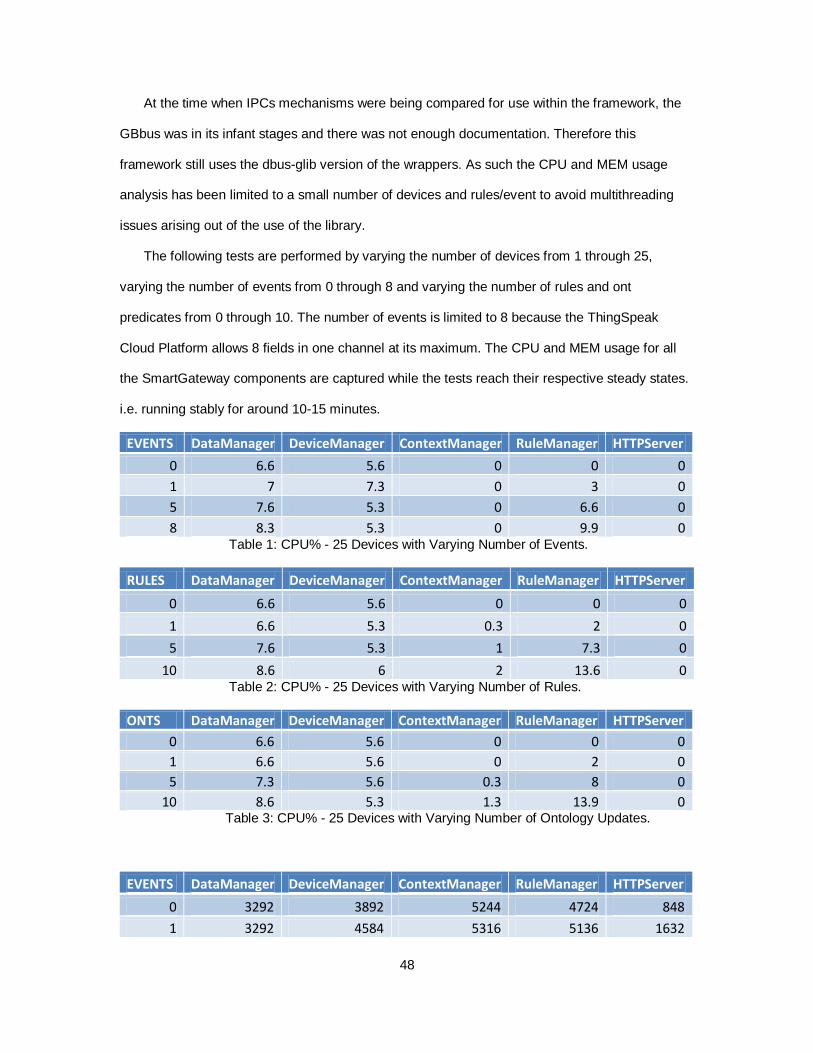
The following tests are performed by varying the number of devices from 1 through 25,
varying the number of events from 0 through 8 and varying the number of rules and ont
predicates from 0 through 10. The number of events is limited to 8 because the ThingSpeak
Cloud Platform allows 8 fields in one channel at its maximum. The CPU and MEM usage for all
the SmartGateway components are captured while the tests reach their respective steady states.
i.e. running stably for around 10-15 minutes.
EVENTS DataManager DeviceManager ContextManager RuleManager HTTPServer
0 6.6 5.6 0 0 0
1 7 7.3 0 3 0
5 7.6 5.3 0 6.6 0
8 8.3 5.3 0 9.9 0 Table 1: CPU% - 25 Devices with Varying Number of Events.
RULES DataManager DeviceManager ContextManager RuleManager HTTPServer
0 6.6 5.6 0 0 0
1 6.6 5.3 0.3 2 0
5 7.6 5.3 1 7.3 0
10 8.6 6 2 13.6 0 Table 2: CPU% - 25 Devices with Varying Number of Rules.
ONTS DataManager DeviceManager ContextManager RuleManager HTTPServer
0 6.6 5.6 0 0 0
1 6.6 5.6 0 2 0
5 7.3 5.6 0.3 8 0
10 8.6 5.3 1.3 13.9 0 Table 3: CPU% - 25 Devices with Varying Number of Ontology Updates.
EVENTS DataManager DeviceManager ContextManager RuleManager HTTPServer
0 3292 3892 5244 4724 848
1 3292 4584 5316 5136 1632
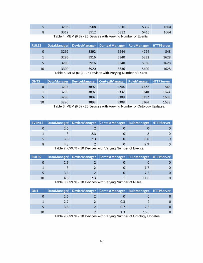
49
5 3296 3908 5316 5332 1664
8 3312 3912 5332 5416 1664 Table 4: MEM (KB) - 25 Devices with Varying Number of Events
RULES DataManager DeviceManager ContextManager RuleManager HTTPServer
0 3292 3892 5244 4724 848
1 3296 3916 5340 5332 1628
5 3296 3916 5340 5336 1628
10 3300 3920 5336 5400 1628 Table 5: MEM (KB) - 25 Devices with Varying Number of Rules.
ONTS DataManager DeviceManager ContextManager RuleManager HTTPServer
0 3292 3892 5244 4727 848
1 3296 3892 5332 5240 1624
5 3296 3892 5308 5312 1688
10 3296 3892 5308 5364 1688 Table 6: MEM (KB) - 25 Devices with Varying Number of Ontology Updates.
EVENTS DataManager DeviceManager ContextManager RuleManager HTTPServer
0 2.6 2 0 0 0
1 3 2.3 0 2 0
5 3.6 2.3 0 6.6 0
8 4.3 2 0 9.9 0 Table 7: CPU% - 10 Devices with Varying Number of Events.
RULES DataManager DeviceManager ContextManager RuleManager HTTPServer
0 2.6 2 0 0 0
1 3 2 0 1.7 0
5 3.6 2 0 7.2 0
10 4.6 2.3 1 11.6 0 Table 8: CPU% - 10 Devices with Varying Number of Rules.
ONT DataManager DeviceManager ContextManager RuleManager HTTPServer
0 2.6 2 0 0 0
1 2.7 2 0.3 2 0
5 3.6 2 0.7 7.6 0
10 5 2 1.3 15.5 0 Table 9: CPU% - 10 Devices with Varying Number of Ontology Updates.
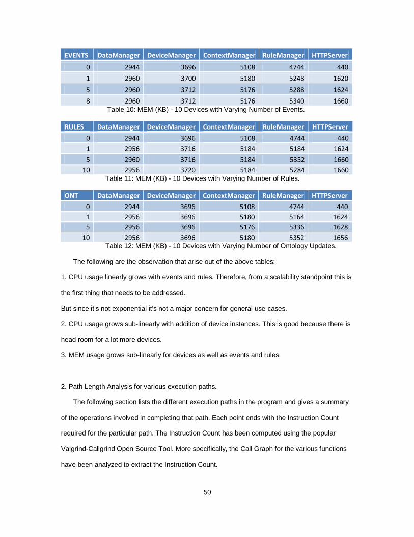
50
EVENTS DataManager DeviceManager ContextManager RuleManager HTTPServer
0 2944 3696 5108 4744 440
1 2960 3700 5180 5248 1620
5 2960 3712 5176 5288 1624
8 2960 3712 5176 5340 1660 Table 10: MEM (KB) - 10 Devices with Varying Number of Events.
RULES DataManager DeviceManager ContextManager RuleManager HTTPServer
0 2944 3696 5108 4744 440
1 2956 3716 5184 5184 1624
5 2960 3716 5184 5352 1660
10 2956 3720 5184 5284 1660 Table 11: MEM (KB) - 10 Devices with Varying Number of Rules.
ONT DataManager DeviceManager ContextManager RuleManager HTTPServer
0 2944 3696 5108 4744 440
1 2956 3696 5180 5164 1624
5 2956 3696 5176 5336 1628
10 2956 3696 5180 5352 1656 Table 12: MEM (KB) - 10 Devices with Varying Number of Ontology Updates.
The following are the observation that arise out of the above tables:
1. CPU usage linearly grows with events and rules. Therefore, from a scalability standpoint this is
the first thing that needs to be addressed.
But since it's not exponential it's not a major concern for general use-cases.
2. CPU usage grows sub-linearly with addition of device instances. This is good because there is
head room for a lot more devices.
3. MEM usage grows sub-linearly for devices as well as events and rules.
2. Path Length Analysis for various execution paths.
The following section lists the different execution paths in the program and gives a summary
of the operations involved in completing that path. Each point ends with the Instruction Count
required for the particular path. The Instruction Count has been computed using the popular
Valgrind-Callgrind Open Source Tool. More specifically, the Call Graph for the various functions
have been analyzed to extract the Instruction Count.
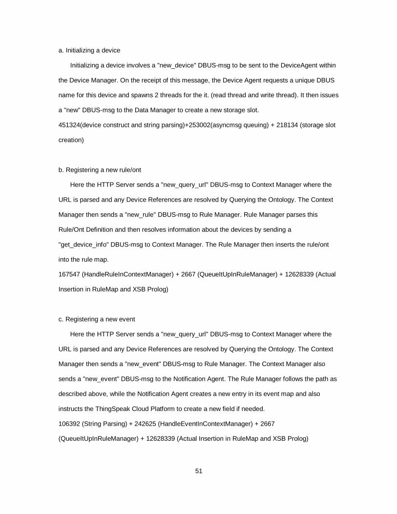
51
a. Initializing a device
Initializing a device involves a "new_device" DBUS-msg to be sent to the DeviceAgent within
the Device Manager. On the receipt of this message, the Device Agent requests a unique DBUS
name for this device and spawns 2 threads for the it. (read thread and write thread). It then issues
a "new" DBUS-msg to the Data Manager to create a new storage slot.
451324(device construct and string parsing)+253002(asyncmsg queuing) + 218134 (storage slot
creation)
b. Registering a new rule/ont
Here the HTTP Server sends a "new_query_url" DBUS-msg to Context Manager where the
URL is parsed and any Device References are resolved by Querying the Ontology. The Context
Manager then sends a "new_rule" DBUS-msg to Rule Manager. Rule Manager parses this
Rule/Ont Definition and then resolves information about the devices by sending a
"get_device_info" DBUS-msg to Context Manager. The Rule Manager then inserts the rule/ont
into the rule map.
167547 (HandleRuleInContextManager) + 2667 (QueueItUpInRuleManager) + 12628339 (Actual
Insertion in RuleMap and XSB Prolog)
c. Registering a new event
Here the HTTP Server sends a "new_query_url" DBUS-msg to Context Manager where the
URL is parsed and any Device References are resolved by Querying the Ontology. The Context
Manager then sends a "new_event" DBUS-msg to Rule Manager. The Context Manager also
sends a "new_event" DBUS-msg to the Notification Agent. The Rule Manager follows the path as
described above, while the Notification Agent creates a new entry in its event map and also
instructs the ThingSpeak Cloud Platform to create a new field if needed.
106392 (String Parsing) + 242625 (HandleEventInContextManager) + 2667
(QueueItUpInRuleManager) + 12628339 (Actual Insertion in RuleMap and XSB Prolog)
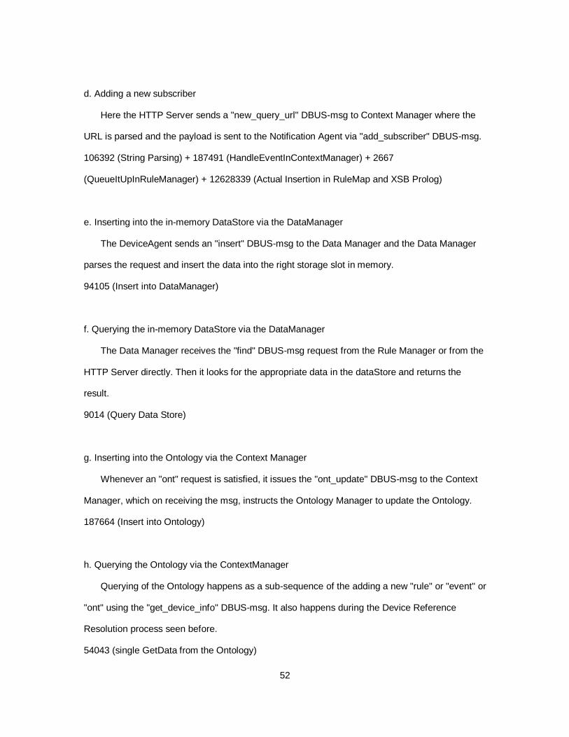
52
d. Adding a new subscriber
Here the HTTP Server sends a "new_query_url" DBUS-msg to Context Manager where the
URL is parsed and the payload is sent to the Notification Agent via "add_subscriber" DBUS-msg.
106392 (String Parsing) + 187491 (HandleEventInContextManager) + 2667
(QueueItUpInRuleManager) + 12628339 (Actual Insertion in RuleMap and XSB Prolog)
e. Inserting into the in-memory DataStore via the DataManager
The DeviceAgent sends an "insert" DBUS-msg to the Data Manager and the Data Manager
parses the request and insert the data into the right storage slot in memory.
94105 (Insert into DataManager)
f. Querying the in-memory DataStore via the DataManager
The Data Manager receives the "find" DBUS-msg request from the Rule Manager or from the
HTTP Server directly. Then it looks for the appropriate data in the dataStore and returns the
result.
9014 (Query Data Store)
g. Inserting into the Ontology via the Context Manager
Whenever an "ont" request is satisfied, it issues the "ont_update" DBUS-msg to the Context
Manager, which on receiving the msg, instructs the Ontology Manager to update the Ontology.
187664 (Insert into Ontology)
h. Querying the Ontology via the ContextManager
Querying of the Ontology happens as a sub-sequence of the adding a new "rule" or "event" or
"ont" using the "get_device_info" DBUS-msg. It also happens during the Device Reference
Resolution process seen before.
54043 (single GetData from the Ontology)
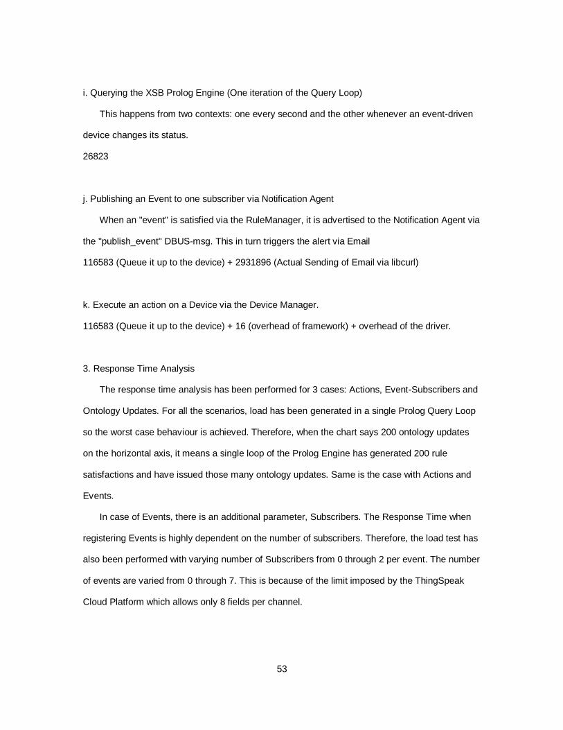
53
i. Querying the XSB Prolog Engine (One iteration of the Query Loop)
This happens from two contexts: one every second and the other whenever an event-driven
device changes its status.
26823
j. Publishing an Event to one subscriber via Notification Agent
When an "event" is satisfied via the RuleManager, it is advertised to the Notification Agent via
the "publish_event" DBUS-msg. This in turn triggers the alert via Email
116583 (Queue it up to the device) + 2931896 (Actual Sending of Email via libcurl)
k. Execute an action on a Device via the Device Manager.
116583 (Queue it up to the device) + 16 (overhead of framework) + overhead of the driver.
3. Response Time Analysis
The response time analysis has been performed for 3 cases: Actions, Event-Subscribers and
Ontology Updates. For all the scenarios, load has been generated in a single Prolog Query Loop
so the worst case behaviour is achieved. Therefore, when the chart says 200 ontology updates
on the horizontal axis, it means a single loop of the Prolog Engine has generated 200 rule
satisfactions and have issued those many ontology updates. Same is the case with Actions and
Events.
In case of Events, there is an additional parameter, Subscribers. The Response Time when
registering Events is highly dependent on the number of subscribers. Therefore, the load test has
also been performed with varying number of Subscribers from 0 through 2 per event. The number
of events are varied from 0 through 7. This is because of the limit imposed by the ThingSpeak
Cloud Platform which allows only 8 fields per channel.
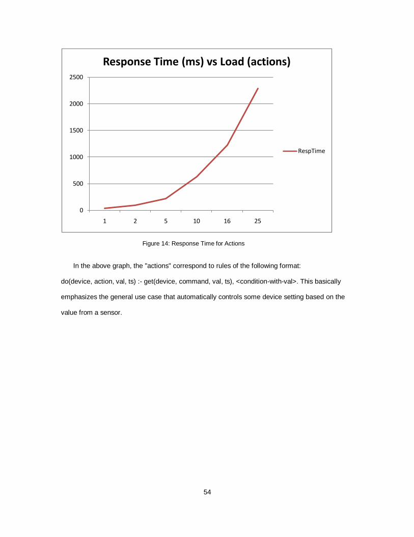
54
Figure 14: Response Time for Actions
In the above graph, the "actions" correspond to rules of the following format:
do(device, action, val, ts) :- get(device, command, val, ts), <condition-with-val>. This basically
emphasizes the general use case that automatically controls some device setting based on the
value from a sensor.
0
500
1000
1500
2000
2500
1 2 5 10 16 25
Response Time (ms) vs Load (actions)
RespTime
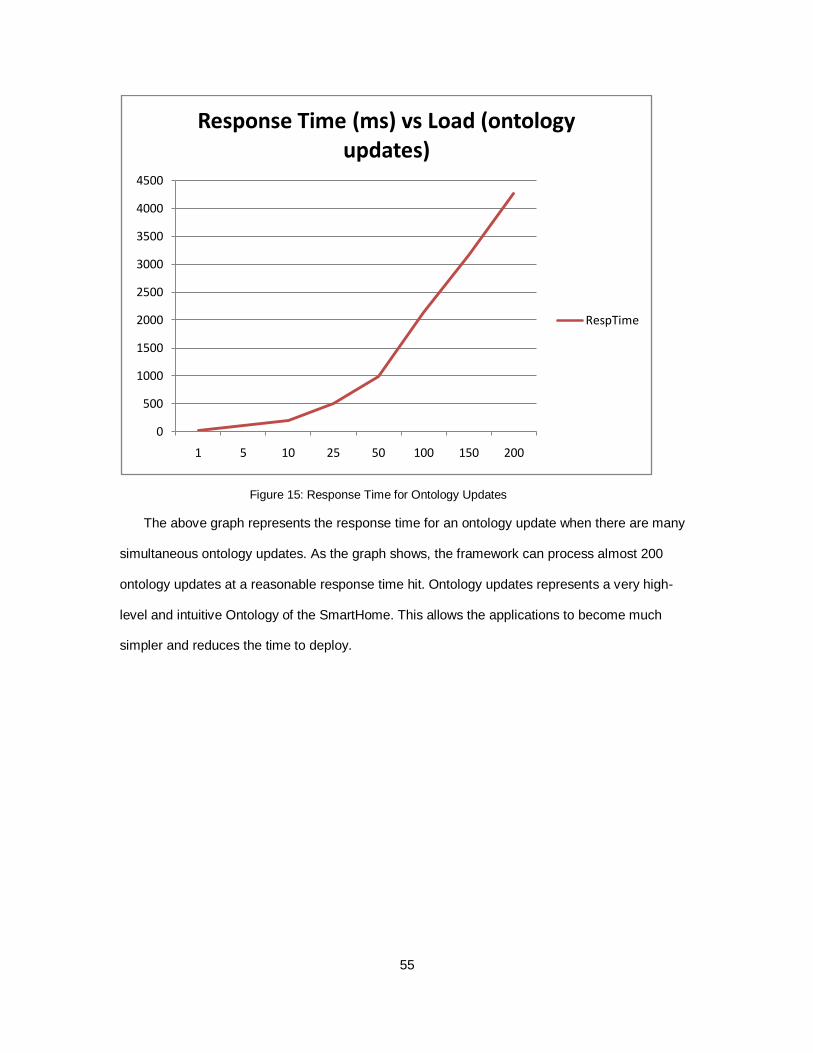
55
Figure 15: Response Time for Ontology Updates
The above graph represents the response time for an ontology update when there are many
simultaneous ontology updates. As the graph shows, the framework can process almost 200
ontology updates at a reasonable response time hit. Ontology updates represents a very high-
level and intuitive Ontology of the SmartHome. This allows the applications to become much
simpler and reduces the time to deploy.
0
500
1000
1500
2000
2500
3000
3500
4000
4500
1 5 10 25 50 100 150 200
Response Time (ms) vs Load (ontology updates)
RespTime
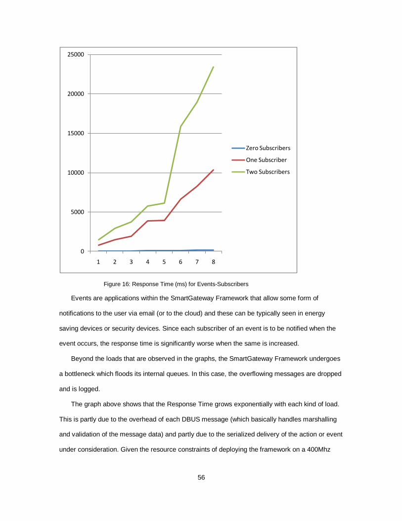
56
Figure 16: Response Time (ms) for Events-Subscribers
Events are applications within the SmartGateway Framework that allow some form of
notifications to the user via email (or to the cloud) and these can be typically seen in energy
saving devices or security devices. Since each subscriber of an event is to be notified when the
event occurs, the response time is significantly worse when the same is increased.
Beyond the loads that are observed in the graphs, the SmartGateway Framework undergoes
a bottleneck which floods its internal queues. In this case, the overflowing messages are dropped
and is logged.
The graph above shows that the Response Time grows exponentially with each kind of load.
This is partly due to the overhead of each DBUS message (which basically handles marshalling
and validation of the message data) and partly due to the serialized delivery of the action or event
under consideration. Given the resource constraints of deploying the framework on a 400Mhz
0
5000
10000
15000
20000
25000
1 2 3 4 5 6 7 8
Zero Subscribers
One Subscriber
Two Subscribers
57
processor and given the number of instructions (as seen in Section 6.1) it needs to execute, this
curve becomes even more pronounced.
That being said, the performance of the framework (and thus the Response Time
Characteristics) can be improved by switching to the GDBus implementation of the DBUS IPC
and optimizing the string parsing utilities used within it.
This concludes the performance benchmarking of the framework.
58
CHAPTER 7
CONCLUSION
This paper has successfully demonstrated a prototype implementation of a SmartGateway
framework that allows a user to quickly build an application involving sensor data and actuators
and with ease and flexibility provided by the HTTP Restful Server. This framework can also be
used to push data to the cloud and visualize it in the form of graphs. This may be useful in finding
trends and patterns within data. Since the Ontology contains an effective representation of a
Smarthome, the framework allows the user to update properties of the Instances within the
Ontology to reflect their current status using the low-level sensor data. The framework is light-
weight and is built to be run on small embedded development boards. Adding new devices to the
framework has been made easier by using the code-generator. This framework also provides an
intuitive and flexible way of querying for sensor data, structural Ontology information or Data
Properties from the Ontology that represent high-level and processed information.
59
REFERENCES
1. Michael Compton, PayamBarnaghi, Luis Bermudez, Raul Garc´ıa-Castro, Oscar Corcho, Simon Cox, John Graybeal, Manfred Hauswirth, Cory Henson, Arthur Herzog, et al. The ssn ontology of the w3c semantic sensor network incubator group. Web Semantics: Science, Services and Agents on the World Wide Web, 17:25–32, 2012
2. "KURA" Eclipse Kura (2015)The Eclipse Foundation. Retrieved from
http://www.eclipse.org/kura/ 3. "HomeKit" Apple HomeKit (2015) Apple Inc. Retrieved from
https://developer.apple.com/homekit/ 4. "nest" Google Nest (2015) Nest Labs. Retrieved from https://nest.com/ 5. Levin, Mikhail (2011) "owl_cpp" Open-source C++ library for parsing, querying and reasoning
with OWL 2 Ontologies. Retrieved from http://sourceforge.net/projects/owl-cpp/files/ 6. Patel-Schneider, Peter Motik, Boris (2012) OWL 2 Web Ontology Language Mapping to RDF
Graphs. W3C Recommendation. Retrieved from http://www.w3.org/TR/owl2-mapping-to-rdf/
Recommended