KAD Air Conditioning Est. P.O. Box 5389, Dubai, UAE. Tel: +971 4 806 7676 Fax: +971 4 806 7688 Email: [email protected] Web: www.kadairconditioning.com
klimaopremaHR-10430 Samobor,
Croatia, Gradna 78A.
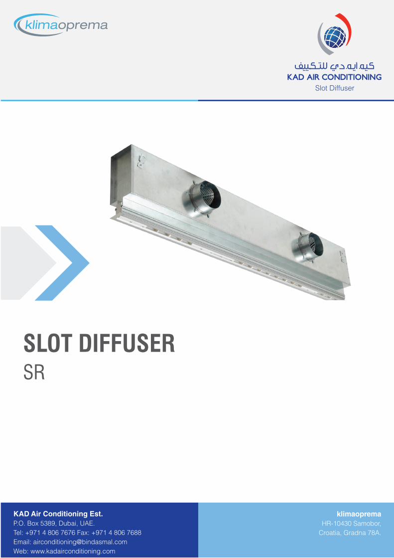
Slot Diffuser
SRSLOT DIFFUSER
Design changes reserved
SLOT DIFFUSER
TABLE OF CONTENTS
Slot diffuser, type SR...................................................................................................................................................... 01
Selection diagrams............................................................................................................................................................ 04
Ordering key....................................................................................................................................................................... 08
Corner section................................................................................................................................................................... 08
Definition of symbols:
Vp [m3/h] - Airflow rate
V [m3/hm] - Airflow rate per meter lengthV2 [m
3/hm2] - Airflow rate per room areaAef [m
2] - Effective outlet areavL [m/s] - Core velocityvh [m/s] - Air velocity between two diffusersL [m] - Diffuser lengthBmin [m] - Distance between two diffusersh [m] - Installation heightLWA [dB(A)] - Sound power level∆p [Pa] - Pressure drop
SLOT DIFFUSER
01Design changes reserved
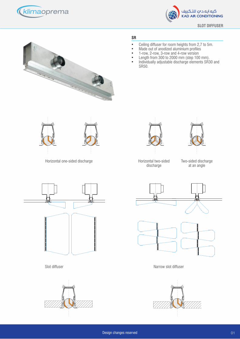
• Ceiling diffuser for room heights from 2,7 to 5m.• Made out of anodized aluminium profiles• 1-row, 2-row, 3-row and 4-row version• Length from 300 to 2000 mm (step 100 mm). • Individually adjustable discharge elements SR30 and
SR50.
SR
Horizontal one-sided discharge Horizontal two-sideddischarge
Two-sided discharge at an angle
Slot diffuser Narrow slot diffuser
Design changes reserved02
SLOT DIFFUSER
TypeNo. of
rows
A ef
[m2/m]
L
[mm]
V
[m3/h m]
h
[m]
B1
[mm]
B2
[mm]
B3
[mm]
A
[mm]
B
[mm]
C
[mm]
øD
[mm]
No. of
connections
E
[mm]
F
[mm]
G
[mm]
SR 3
0
1 0,00752
do 1000
40 -1302,7
-4,028 47,5 35 221 120 174
98 1 L / 2
47,5
471100-1500 98 2 300
1600-2000 123 2 400
2 0,01504
do 1000
70 -2402,7
-4,555 74,5 62 236 150 189
138 1 L / 2
471100-1500 123 2 300
1600-2000 138 2 400
3 0,02256
do 1000
120 -3203,0
-5,082 101,5 89 261 179 215
158 1 L / 2
471100-1500 138 2 300
1600-2000 158 2 400
4 0,03008
do 1000
160 -4003,5
-5,0109 128,5 119 301 210 255
198 1 L / 2
471100-1500 158 2 300
1600-2000 198 2 400
TypeNo. of
rows
A ef
[m2/m]
L
[mm]
V
[m3/h m]
h
[m]
B1
[mm]
B2
[mm]
B3
[mm]
A
[mm]
B
[mm]
C
[mm]
ø D
[mm]
No. of
connections
E
[mm]
F
[mm]
G
[mm]
SR 5
0
1 0,01504
do 1000
75 -2102,7
-4,043,5 71 51 252 130 195
123 1 L / 2
57,5
571100-1500 123 2 300
1600-2000 138 2 400
2 0,03008
do 1000
130 -3902,7
-4,593,5 121 101 272 180 215
158 1 L / 2
571100-1500 138 2 300
1600-2000 158 2 400
3 0,04512
do 1000
195 -5203,0
-5,0143,5 171 151 312 230 255
198 1 L / 2
571100-1500 158 2 300
1600-2000 198 2 400
4 0,06016
do 1000
260 -6503,5
-5,0193,5 221 201 337 280 280
223 1 L / 2
571100-1500 198 2 300
1600-2000 223 2 400
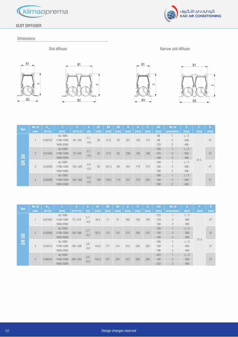
B1
B2
F
B1
B2F
B2F
B1 B1
B3
F
B1
B2
F
B3
F
B1
Slot diffuser Narrow slot diffuser
Dimensions
SLOT DIFFUSER
03Design changes reserved
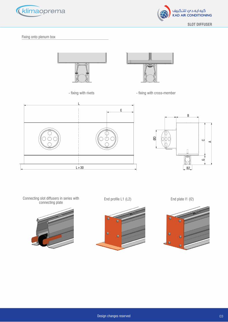
Connecting slot diffusers in series with connecting plate
Fixing onto plenum box
- fixing with rivets - fixing with cross-member
End profile L1 (L2) End plate I1 (I2)
B
ØD
G
AC
B2
E
L+30
L
Design changes reserved04
SLOT DIFFUSER
80
200
300
600
400
500
700
250
150
100
70
60
50
402,2 3,0 4,0 5,0
SR 30-1V max
SR 30-1V min
SR 30-2V max
SR 30-2V min
SR 30-3V min
SR 30-3V max
SR 30-4V max
SR 30-4V min
V [m
3 /hm
]
h [m]
260,15 0,25 0,35 0,40
283032343638404244464850525456
2,5
3,0
4,05,0
h [m
]
vL [m/s]
V 2 [m
3 /hm
2 ]
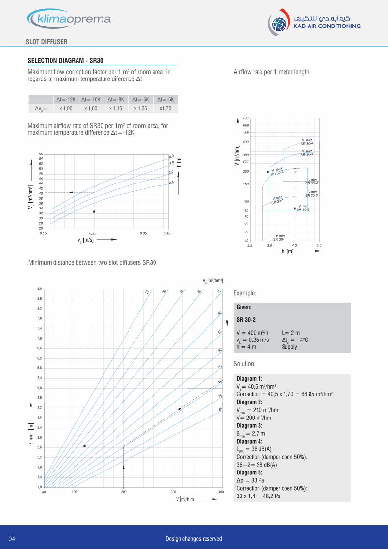
∆t=-12K ∆t=-10K ∆t=-8K ∆t=-6K ∆t=-6K
∆Vp= x 1,00 x 1,00 x 1,15 x 1,35 x1,70
B m
inm
1,040 100 200 300
1,4
1,8
2,2
2,6
3,0
3,4
3,8
4,2
V m3/h m
400
55
25
60
65
70
75
80
4,6
5,0
5,4
5,8
6,2
6,6
7,0
7,4
7,8
8,2
8,6
9,0
V2 [m3/hm2]
35 40
50
4530
SELECTION DIAGRAM - SR30
Minimum distance between two slot diffusers SR30
Maximum flow correction factor per 1 m2 of room area, in regards to maximum temperature diference ∆t
Airflow rate per 1 meter length
Maximum airflow rate of SR30 per 1m2 of room area, for maximum temperature difference ∆t=-12K
Example:
Given:
SR 30-2
V = 400 m3/h L= 2 mvL = 0,25 m/s ∆tZ = - 4°C h = 4 m Supply
Solution:
Diagram 1: V2= 40,5 m3/hm2
Correction = 40,5 x 1,70 = 68,85 m3/hm2
Diagram 2:Vmax = 210 m3/hmV= 200 m3/hmDiagram 3:Bmin = 2,7 mDiagram 4:LWA = 36 dB(A)Correction (damper open 50%): 36+2= 38 dB(A)Diagram 5:∆p = 33 PaCorrection (damper open 50%): 33 x 1,4 = 46,2 Pa
SLOT DIFFUSER
05Design changes reserved
5
9080
200
300
600
400
500
700
250
150
100
70
60
50
4010 15 20 30 5040 10060 70 80
SR 30-4
SR 30-3
SR 30-2
SR 30-1
Vm3 /h
m
p Pa
5
9080
200
300
600
400
500
700
250
150
100
70
60
50
4010 15 20 30 5040 10060 70 80
p Pa
SR 30-4
SR 30-3
SR 30-2
SR 30-1
Vm3 /h
m
9080
200
300
600
400
500
700
250
150
100
70
60
50
402 10 20 30
V [m
3 /hm
]
L WA dB (A)
40 50
SR 30-4
SR 30-3
SR 30-2
SR 30-1
L < 1200
L > 1200
Duljina raspora SR 30
9080
200
300
600
400
500
700
250
150
100
70
60
50
402 10 20 30
V [m
3 /hm
]
L WA dB (A)
40 50
SR 30-4
SR 30-3
SR 30-2
SR 30-1
L < 1200
L > 1200
Duljina raspora SR 30
Damper position
100% open
75% open
50% open
25% open
0% open
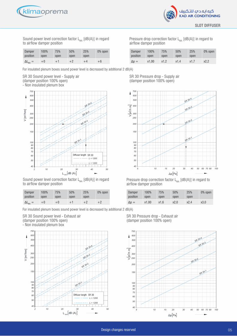
∆LWA = +0 +1 +2 +4 +6
Damper position
100% open
75% open
50% open
25% open
0% open
∆p = x1,00 x1,2 x1,4 x1,7 x2,2
Damper position
100% open
75% open
50% open
25% open
0% open
∆p = x1,00 x1,6 x2,0 x2,4 x3,0
Pressure drop correction factor LWA [dB(A)] in regard to airflow damper position
Damper position
100% open
75% open
50% open
25% open
0% open
∆LWA = +0 +0 +1 +2 +2
Sound power level correction factor LWA [dB(A)] in regard to airflow damper position
SR 30 Sound power level - Supply air(damper position 100% open)- Non insulated plenum box
SR 30 Pressure drop - Supply air(damper position 100% open)
SR 30 Sound power level - Exhaust air(damper position 100% open)- Non insulated plenum box
SR 30 Pressure drop - Exhaust air(damper position 100% open)
Sound power level correction factor LWA [dB(A)] in regard to airflow damper position
Pressure drop correction factor LWA [dB(A)] in regard to airflow damper position
For insulated plenum boxes sound power level is decreased by additional 2 dB(A)
For insulated plenum boxes sound power level is decreased by additional 2 dB(A)
Diffuser length
Diffuser length
Design changes reserved06
SLOT DIFFUSER
B m
inm
1,080 200 400 600
1,4
1,8
2,2
2,6
3,0
3,4
3,8
4,2
V m3/h m
800
55
25
60
65
70
75
80
4,6
5,0
5,4
5,8
6,2
6,6
7,0
7,4
7,8
8,2
8,6
9,0
Protok zraka po kvadratu površine prostorije Vp [m3/hm2]
35 40
50
4530
9080
200
300
600
400
500
700
250
150
100
70
602,2 3,0 4,0 5,0
SR 50-1V max
SR 50-1V min
SR 50-2
V max
SR 50-2V min
SR 50-3V min
SR 50-3V max
SR 50-4V max
SR 50-4V min
h [m]V
[m3 /h
m]
2628303234363840
45
50
70
80
2,5
3,0
4,0
5,0
h [m
]
0,15 0,25 0,35 0,40
vL [m/s]
V [m
3 /hm
2 ]
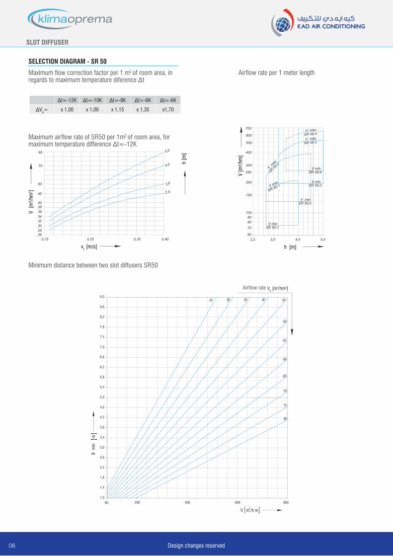
SELECTION DIAGRAM - SR 50
Minimum distance between two slot diffusers SR50
Maximum airflow rate of SR50 per 1m2 of room area, for maximum temperature difference ∆t=-12K
Airflow rate per 1 meter lengthMaximum flow correction factor per 1 m2 of room area, in regards to maximum temperature diference ∆t
∆t=-12K ∆t=-10K ∆t=-8K ∆t=-6K ∆t=-6K
∆Vp= x 1,00 x 1,00 x 1,15 x 1,35 x1,70
Airflow rate
SLOT DIFFUSER
07Design changes reserved155
9080
200
300
600
400
500
700
250
150
100
70
60
50
402 10 20 30
V [m
3 /hm
]
L WA [dB(A)]
40 50
SR 50-4
SR 50-2
SR 50-1
duljina raspora SR 50
L < 1200
L > 1200
SR 50-3
5
9080
200
300
600
400
500
700
250
150
100
70
60
50
4010 15 20 30 5040 10060 70 80
SR 50-4
( Vrijedi za otvorenu regulacijsku zaklopku na priklju čnoj kutiji )
SR 50-3
SR 50-2
SR 50-1
V [m
3 /hm
]
∆p [Pa]
9080
200
300
600
400
500
700
250
150
100
70
60
50
402 10 20 30 40 50
SR 50-4SR 50-3
SR 50-1
duljina raspora SR 50
L < 1200
L > 1200
( Vrijedi za otvorenu regulacijsku zaklopku na priklju čnoj kutiji - priključna kutija neizolirana)
SR 50-2
V [m
3 /hm
]
L WA [dB(A)]
5
9080
200
300
600
400
500
700
250
150
100
70
60
50
4010 15 20 30 5040 10060 70 80
SR 50-2
SR 50-1
( Vrijedi za otvorenu regulacijsku zaklopku na priklju čnoj kutiji )
SR 50-4
SR 50-3
∆p [Pa]
V [m
3 /hm
]
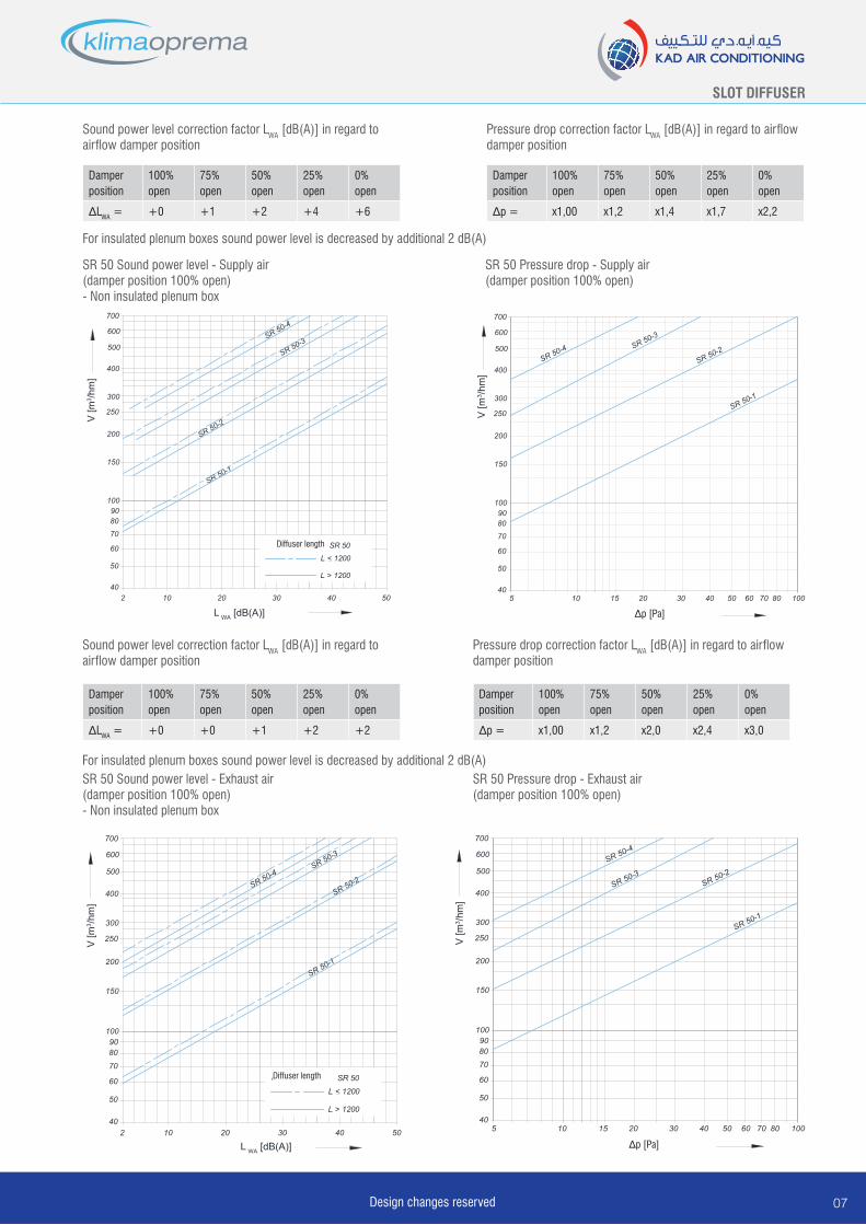
Sound power level correction factor LWA [dB(A)] in regard to airflow damper position
Damperposition
100% open
75% open
50% open
25% open
0% open
∆LWA = +0 +1 +2 +4 +6
Pressure drop correction factor LWA [dB(A)] in regard to airflow damper position
Damperposition
100% open
75% open
50% open
25% open
0% open
∆p = x1,00 x1,2 x1,4 x1,7 x2,2
For insulated plenum boxes sound power level is decreased by additional 2 dB(A)
SR 50 Sound power level - Supply air(damper position 100% open)- Non insulated plenum box
SR 50 Pressure drop - Supply air(damper position 100% open)
Sound power level correction factor LWA [dB(A)] in regard to airflow damper position
Damperposition
100% open
75% open
50% open
25% open
0% open
∆LWA = +0 +0 +1 +2 +2
Pressure drop correction factor LWA [dB(A)] in regard to airflow damper position
Damperposition
100% open
75% open
50% open
25% open
0% open
∆p = x1,00 x1,2 x2,0 x2,4 x3,0
For insulated plenum boxes sound power level is decreased by additional 2 dB(A)SR 50 Sound power level - Exhaust air(damper position 100% open)- Non insulated plenum box
SR 50 Pressure drop - Exhaust air(damper position 100% open)
Diffuser length
Diffuser length
Design changes reserved08
SLOT DIFFUSER
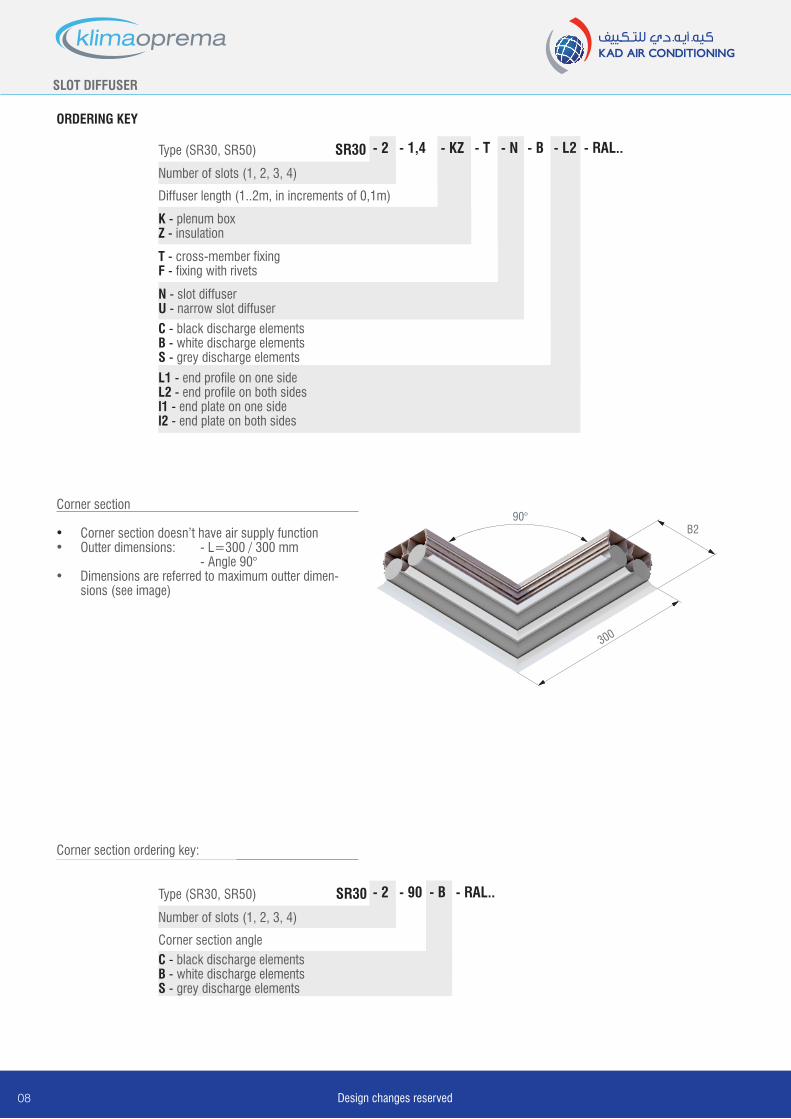
ORDERING KEY
Type (SR30, SR50) SR30 - KZ - T - N - 1,4 - B - L2
L1 - end profile on one sideL2 - end profile on both sidesl1 - end plate on one sidel2 - end plate on both sides
- 2
Corner section
• Corner section doesn’t have air supply function• Outter dimensions: - L=300 / 300 mm - Angle 90°• Dimensions are referred to maximum outter dimen-
sions (see image)
Type (SR30, SR50) SR30 - 90 - B
C - black discharge elementsB - white discharge elementsS - grey discharge elements
- 2
Corner section ordering key:
Number of slots (1, 2, 3, 4)
- RAL..
Number of slots (1, 2, 3, 4)
Corner section angle
- RAL..
N - slot diffuserU - narrow slot diffuser
T - cross-member fixingF - fixing with rivets
K - plenum boxZ - insulation
Diffuser length (1..2m, in increments of 0,1m)
C - black discharge elementsB - white discharge elementsS - grey discharge elements
B290°
300
SLOT DIFFUSER
Design changes reserved
NOTES:

CONTACT US
KAD Air Conditioning Est. P.O. Box 5389, Dubai, UAE. Tel: +971 4 806 7676 Fax: +971 4 806 7688 Email: [email protected] Web: www.kadairconditioning.com
klimaopremaHR-10430 Samobor,
Croatia, Gradna 78A.
Recommended


![Klimaoprema katalog PPZEN DIFFUSER SLOT DIFFUSER ... Selection diagrams ... - Air velocity between two diffusers L [m] - Diffuser length B min](https://img.pdfslide.us/doc/110x75/5a9ff9c87f8b9a71178d6c6b/pdfklimaoprema-katalog-diffuser-slot-diffuser-selection-diagrams-air.jpg)