MASTER DESIGN STUDIO

CONTENT
01 CASE STUDY
02 CEILING SYSTEM STUDY
03 SITE ANALYSIS03 SITE ANALYSIS
04 DESIGN IDEAS
05 SCHEME : MINIMAL SURFACE
06 SCHEME : STICKS ITERATION
07 SCHEME : FOLDING HEXAGON
08 FOLDING HEXAGON : FINAL PROPOSAL
09 FINAL CEILING INSTALLATION

01 CASE STUDY

01 CASE STUDY
INTRODUCTION
SWOOSH PAVILION 2008 Summer Pavilion, Architectural Association students, Bedford Square, London
The pavilion has been designed and constructed by students in Intermediate Unit 2 t th A hit t l A i ti S h l f A hit t (AA) It ti b t at the Architectural Association School of Architecture (AA). Its timber components
were fabricated, again by the students, at the AA’s workshop in Hooke Park, Dorset. The Project is an exploration of contemporary tools and techniques of architectural modeling and visualization. It incorporates new fabrication methods and digital crafting techniques such as computer-integrated manufacturing. The aim is to experiment with – and exploit to the full – the imaginative spatial and material effects that can be extracted from these new-found techniques.
Design Brief: create a pavilion for 100 people with some level of enclosureDesign Brief: create a pavilion for 100 people with some level of enclosure

DESIGN CONCEPT
01 CASE STUDY
Concept: Valeria Garcia; Scheme design with Katarina Scoufaridou and Joy Sriyuksiri; development with Zamri Arip, Naoki Kotaka and Eyal Shaviv.
Concept of the Swoosh Pavilion came of studying the deformation of an optical model in 2D. Optical qualities were extracted from the visual dynamic and interpreted in 3D –the flow and movement.p
“We wanted to create an interactive space where people could share different experiences, like holding informal meetings, sitting, having lunch — all under one roof,” says student Eyal Shaviv.

DESIGN DEVELOPMENT
01 CASE STUDY
As for the form, fluidity was the driving factor. “The main goal was to create a sense of flow,” says student Katrina Scoufaridou. “We have used many vertical pieces, but because they are connected to form a grid, the whole structure has a sense of cohesion.”
The plan is devised around two setting points, A and B, and two identical columns, A01 and B01, which run between the two. From the setting points, 30 more columns spiral outwards in each direction, creating a completely symmetrical form. Columns A01 and B01 form an archway, 3.3m in height. The remaining columns then get taller as they cantilever out to create a partly enclosed space.
DESIGN DEVELOPMENT
01 CASE STUDY
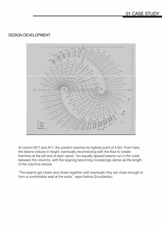
At column B17 and A17, the pavilion reaches its highest point of 4.5m. From here, the beams reduce in height eventually reconnecting with the floor to create the beams reduce in height, eventually reconnecting with the floor to create benches at the tail end of each spiral. Ten equally spaced beams run in the voids between the columns, with the spacing becoming increasingly dense as the length of the columns reduce.
“The beams get closer and closer together until eventually they are close enough to form a comfortable seat at the ends,” says Katrina Scoufaridou.

DESIGN PROCESS
01 CASE STUDY
Software programs Rhino and AutoCAD were used to design the original concept: AutoCAD mainly for measurements and labeling, and Rhino for quicker modeling and 3D visualization.
The pavilion’s complex geometry meant they had to switch from a computing scripting model to handcrafted 3D models, calculating many details by themselves.

TEAM WORK
01 CASE STUDY
Design Team Leader – in charge of the transition between design drawings into construction drawings.
Workshop Leader – in charge of the production process in the workshop workshop.
Architectural Association Tutor– Guidance and support.
Consultant – Structural Engineer from Arup – Lighting concept consultant from Illumination Works
Contractor– Assisting in on site construction and crane operation.
FABRICATION
01 CASE STUDY
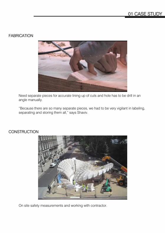
Need separate pieces for accurate lining up of cuts and hole has to be drill in an angle manually.
“Because there are so many separate pieces, we had to be very vigilant in labeling, separating and storing them all,” says Shaviv.
CONSTRUCTION
On site safety measurements and working with contractor.
MATERIAL
01 CASE STUDY
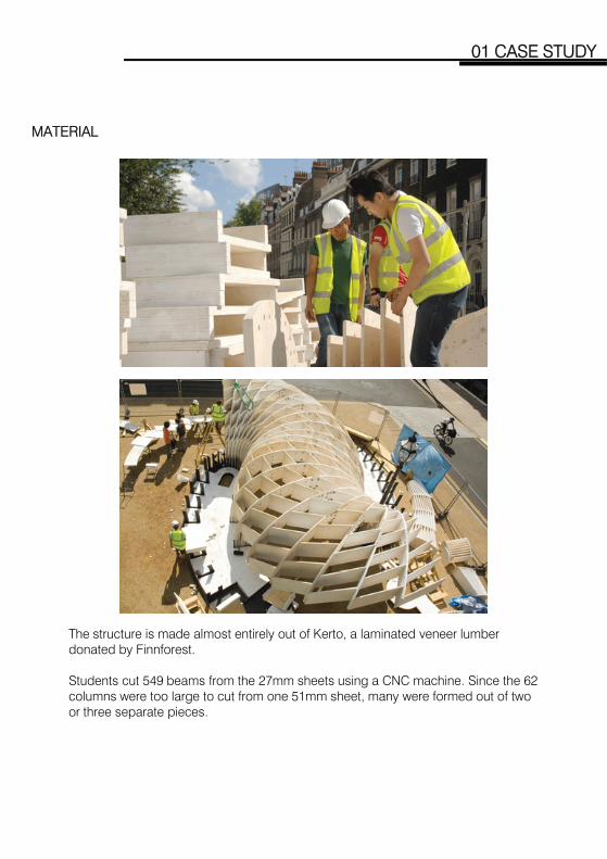
The structure is made almost entirely out of Kerto, a laminated veneer lumber donated by Finnforest.
Students cut 549 beams from the 27mm sheets using a CNC machine. Since the 62 columns were too large to cut from one 51mm sheet, many were formed out of two or three separate piecesor three separate pieces.
CONNECTION
01 CASE STUDY
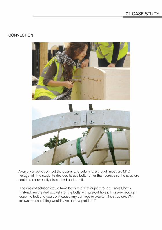
A variety of bolts connect the beams and columns, although most are M12 hexagonal. The students decided to use bolts rather than screws so the structure could be more easily dismantled and rebuilt.
“The easiest solution would have been to drill straight through,” says Shaviv. “I t d t d k t f th b lt ith t h l Thi “Instead, we created pockets for the bolts with pre-cut holes. This way, you can reuse the bolt and you don’t cause any damage or weaken the structure. With screws, reassembling would have been a problem.”
02 CEILING SYSTEM STUDY

02 CEILING SYSTEM STUDY
UNIVERSITY OF MELBOURNE
Architecture Building Reflected Ceiling Plan

DOCUMENTATION OF RAILS AND FIXINGS
02 CEILING SYSTEM STUDY
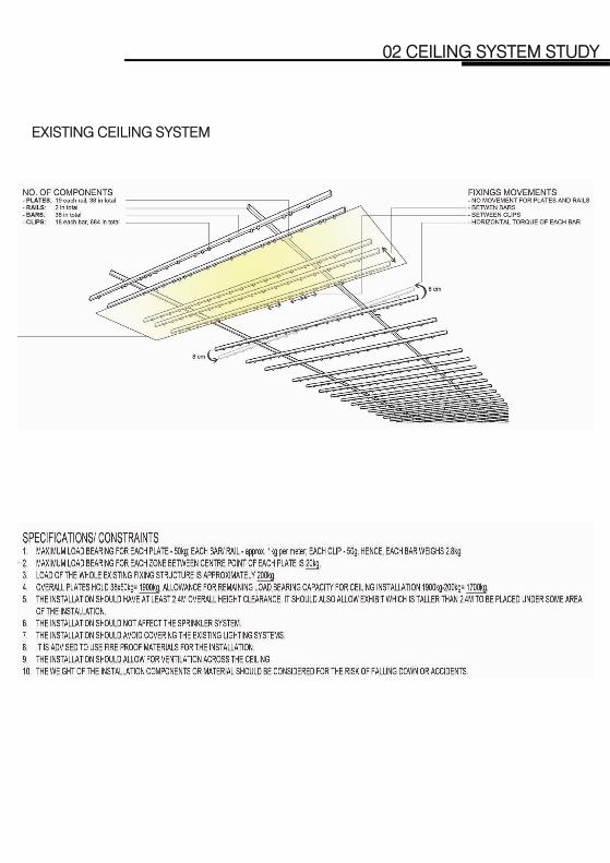
EXISTING CEILING SYSTEM
02 CEILING SYSTEM STUDY
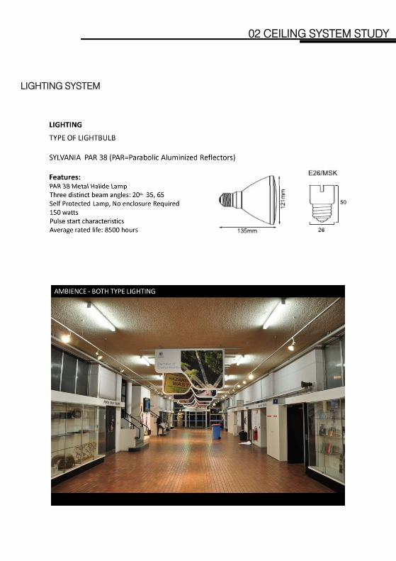
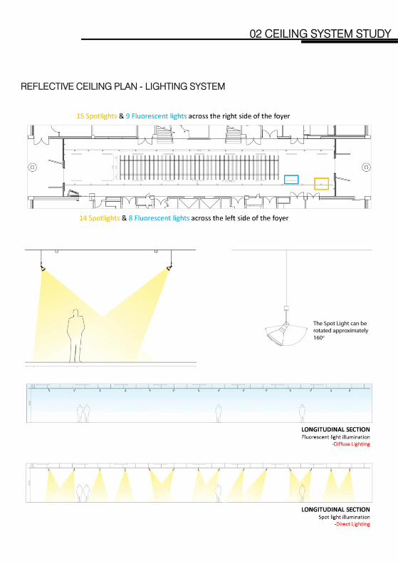
LIGHTING SYSTEM
02 CEILING SYSTEM STUDY

02 CEILING SYSTEM STUDY
02 CEILING SYSTEM STUDY
REFLECTIVE CEILING PLAN - LIGHTING SYSTEM

02 CEILING SYSTEM STUDY
LIFT ANALYSIS

03 SITE ANALYSIS
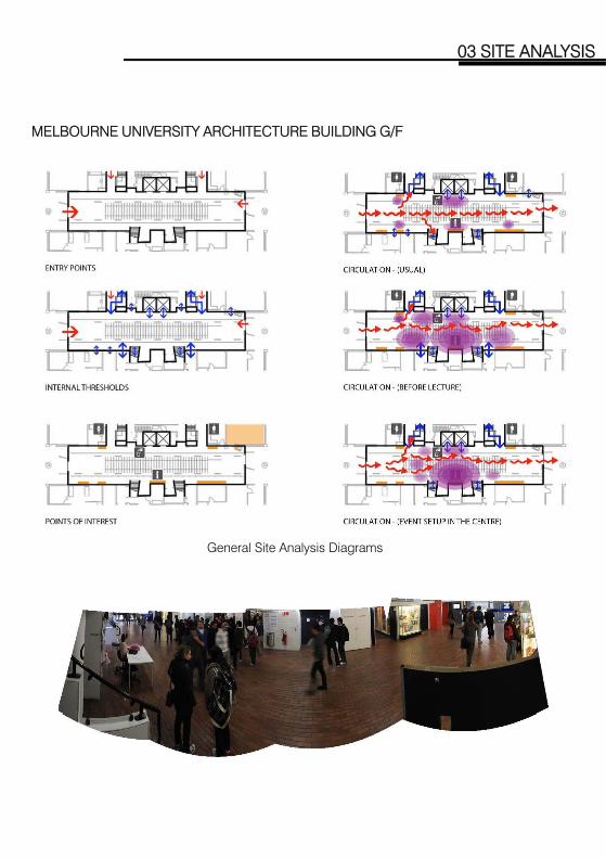
MELBOURNE UNIVERSITY ARCHITECTURE BUILDING G/F
03 SITE ANALYSIS
General Site Analysis Diagrams

TIME LASPE PHOTOGRAPHS ON SITE
03 SITE ANALYSIS
Shots taken every 5mins from 11:45 to 15:30 on a weekday at Architecture Building G/F as a test run to observe people activities on site. It was found that a shot every 5mins is not recording the people movements and the time interval is too short as well.

VIDEO RECORDING ON SITE
03 SITE ANALYSIS
Video was filmed from 6:00 to 24:00 on weekday at Architecture Building G/F to gather information such as people movement and pattern of people gathering at different period of times. Information is then translated into diagrams.
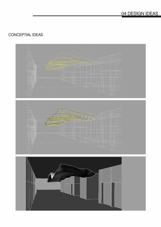
04 DESIGN IDEAS
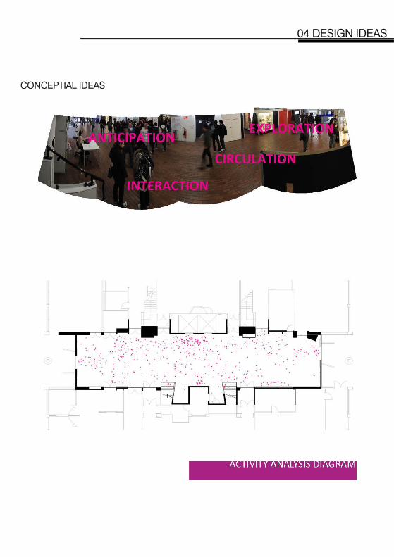
CONCEPTIAL IDEAS
04 DESIGN IDEAS

CONCEPTIAL IDEAS
04 DESIGN IDEAS

CONCEPTIAL IDEAS
04 DESIGN IDEAS

CONCEPTIAL IDEAS
04 DESIGN IDEAS
CONCEPTIAL IDEAS
04 DESIGN IDEAS

CONCEPTIAL IDEAS – A SURFACE THAT SHAPES SPACE
04 DESIGN IDEAS

OPTION 1 – CONICAL OCCULI
04 DESIGN IDEAS
OPTION 2 – FOLDING SURFACE

OPTION 3 – SKIN AND BONE
04 DESIGN IDEAS

MODELING THE SURFACE USING WAFFLE STRUCTURE
04 DESIGN IDEAS

MODELING THE SURFACE
04 DESIGN IDEAS

05 SCHEME : MINIMAL SURFACE

DESIGN CONCEPT
05 SCHEME: MINIMAL SURFACE
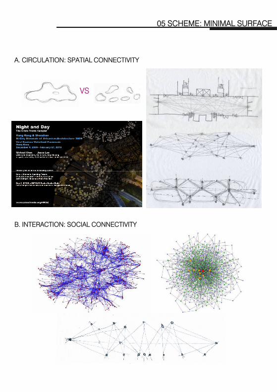
A. CIRCULATION: SPATIAL CONNECTIVITY
05 SCHEME: MINIMAL SURFACE
VS
B. INTERACTION: SOCIAL CONNECTIVITY
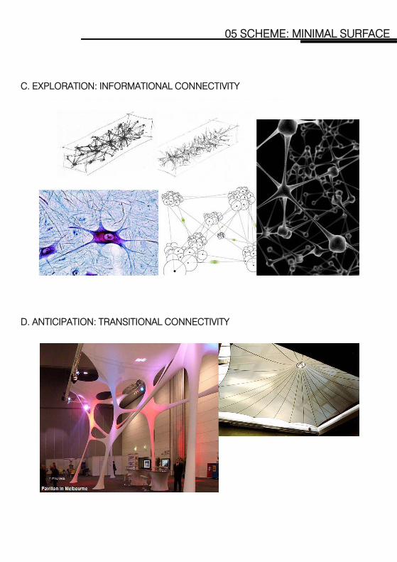
C. EXPLORATION: INFORMATIONAL CONNECTIVITY
05 SCHEME: MINIMAL SURFACE
D. ANTICIPATION: TRANSITIONAL CONNECTIVITY
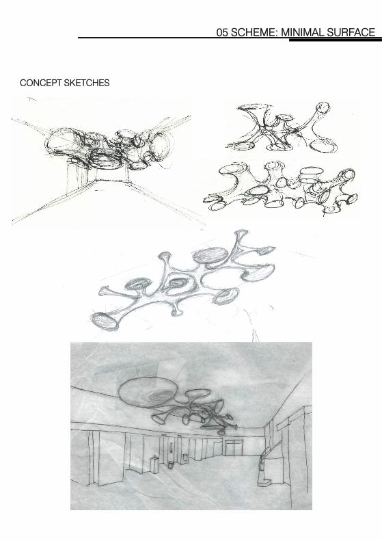
CONCEPT SKETCHES
05 SCHEME: MINIMAL SURFACE

05 SCHEME: MINIMAL SURFACE
MATERIAL RESEARCH
05 SCHEME: MINIMAL SURFACE
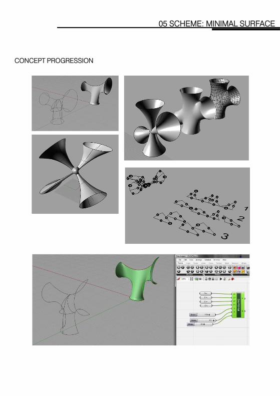
CONCEPT PROGRESSION

06 SCHEME : STICKS ITERATION
06 SCHEME: STICK ITERATION
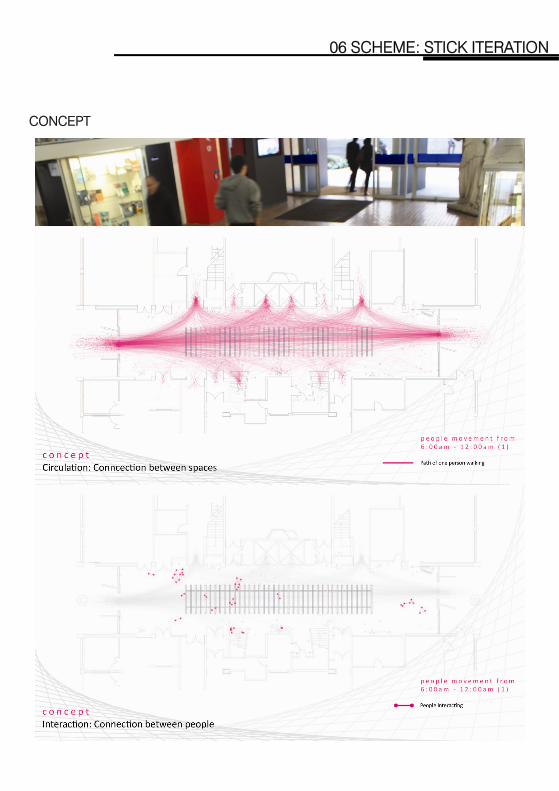
CONCEPT

06 SCHEME: STICK ITERATION
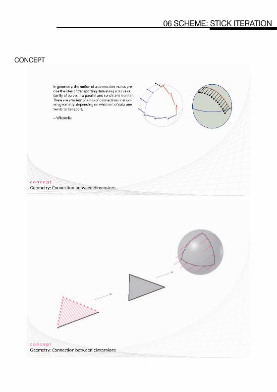
CONCEPT
06 SCHEME: STICK ITERATION
CONCEPT

06 SCHEME: STICK ITERATION
CONCEPT
06 SCHEME: STICK ITERATION
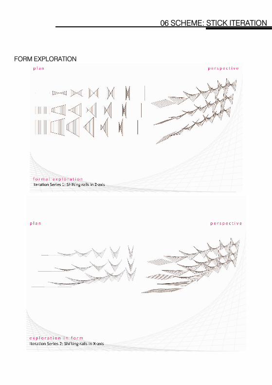
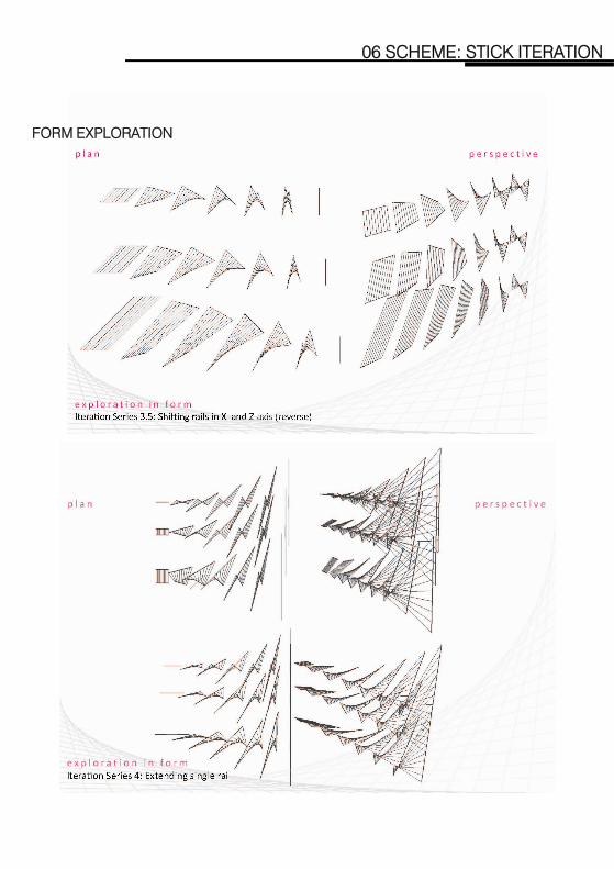
FORM EXPLORATION

06 SCHEME: STICK ITERATION
FORM EXPLORATION
06 SCHEME: STICK ITERATION
FORM EXPLORATION

06 SCHEME: STICK ITERATION
CONSTRUCTION DETAILS
STUDY MODEL

06 SCHEME: STICK ITERATION
PROPOSAL 1

06 SCHEME: STICK ITERATION
PROPOSAL 2

06 SCHEME: STICK ITERATION
PROPOSAL 3

06 SCHEME: STICK ITERATION
PHYSICAL MODEL (SCALE 1:25)
07 SCHEME : FOLDING HEXAGON

07 SCHEME: FOLDING HEXAGON
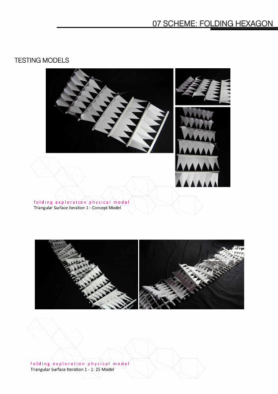
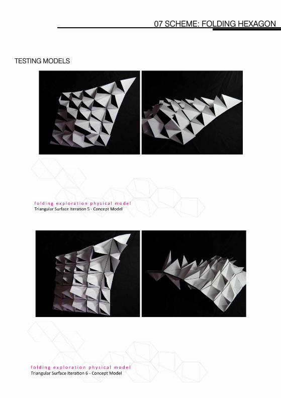
TESTING MODELS

07 SCHEME: FOLDING HEXAGON
TESTING MODELS
07 SCHEME: FOLDING HEXAGON
TESTING MODELS

07 SCHEME: FOLDING HEXAGON
TESTING MODELS

07 SCHEME: FOLDING HEXAGON
TESTING MODELS
07 SCHEME: FOLDING HEXAGON
TESTING MODELS

07 SCHEME: FOLDING HEXAGON
CONCEPT MODEL

07 SCHEME: FOLDING HEXAGON
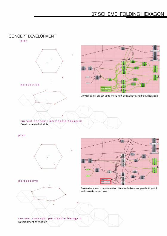
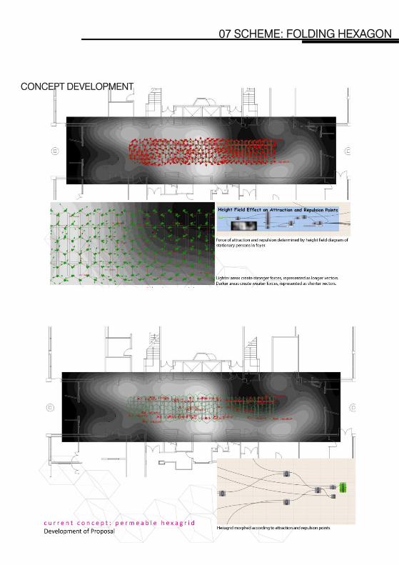
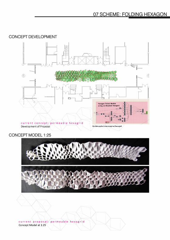
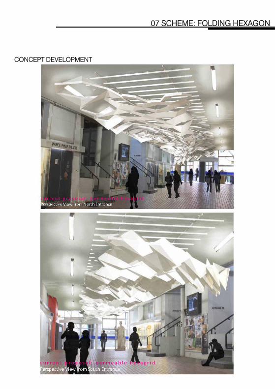
CONCEPT DEVELOPMENT
07 SCHEME: FOLDING HEXAGON
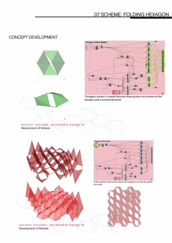
CONCEPT DEVELOPMENT

07 SCHEME: FOLDING HEXAGON
CONCEPT DEVELOPMENT
07 SCHEME: FOLDING HEXAGON
CONCEPT DEVELOPMENT

07 SCHEME: FOLDING HEXAGON
CONCEPT DEVELOPMENT

07 SCHEME: FOLDING HEXAGON
CONCEPT DEVELOPMENT
07 SCHEME: FOLDING HEXAGON
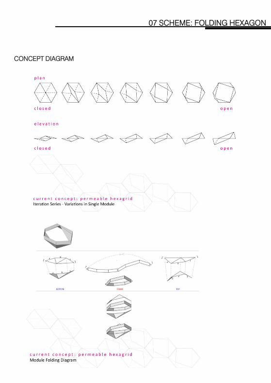
CONCEPT DIAGRAM

07 SCHEME: FOLDING HEXAGON
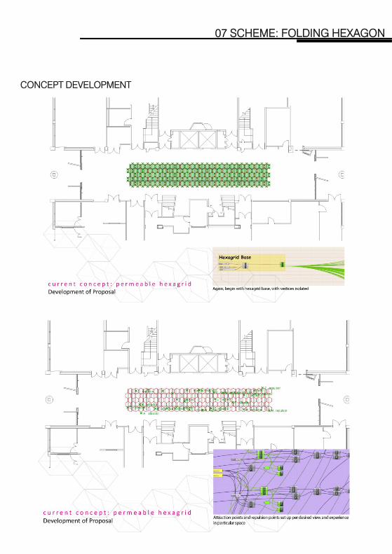
CONCEPT DEVELOPMENT

07 SCHEME: FOLDING HEXAGON
CONCEPT DEVELOPMENT

07 SCHEME: FOLDING HEXAGON
CONCEPT DEVELOPMENT
07 SCHEME: FOLDING HEXAGON
CONCEPT DEVELOPMENT
07 SCHEME: FOLDING HEXAGON
CONCEPT DEVELOPMENT
07 SCHEME: FOLDING HEXAGON
CONCEPT DEVELOPMENT
CONCEPT MODEL 1:25
07 SCHEME: FOLDING HEXAGON
CONCEPT DEVELOPMENT
07 SCHEME: FOLDING HEXAGON
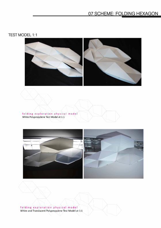
TEST MODEL 1:1

08 FOLDING HEXAGON : FINAL PROPOSAL
08 FOLDING HEXAGON: FINAL PROPOSAL
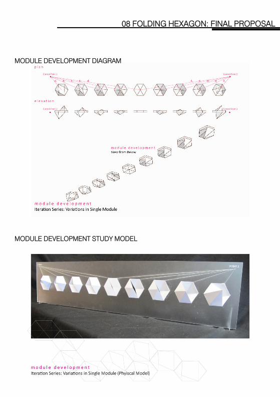
MODULE DEVELOPMENT DIAGRAM
MODULE DEVELOPMENT STUDY MODEL

MODULE DEVELOPMENT
08 FOLDING HEXAGON: FINAL PROPOSAL
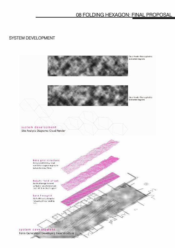
SYSTEM DEVELOPMENT

SYSTEM DEVELOPMENT
08 FOLDING HEXAGON: FINAL PROPOSAL
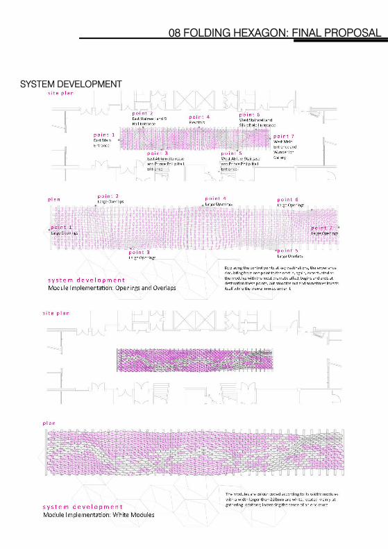
SYSTEM DEVELOPMENT
08 FOLDING HEXAGON: FINAL PROPOSAL

SYSTEM DEVELOPMENT
08 FOLDING HEXAGON: FINAL PROPOSAL

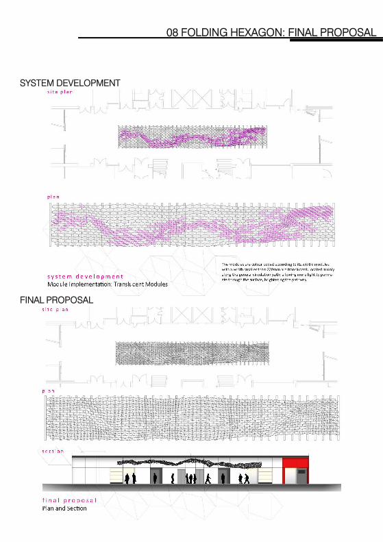
SYSTEM DEVELOPMENT
08 FOLDING HEXAGON: FINAL PROPOSAL
SYSTEM DEVELOPMENT
08 FOLDING HEXAGON: FINAL PROPOSAL
SYSTEM DEVELOPMENT
08 FOLDING HEXAGON: FINAL PROPOSAL
FINAL PROPOSAL

CONSTRUCTION DETAILS
08 FOLDING HEXAGON: FINAL PROPOSAL
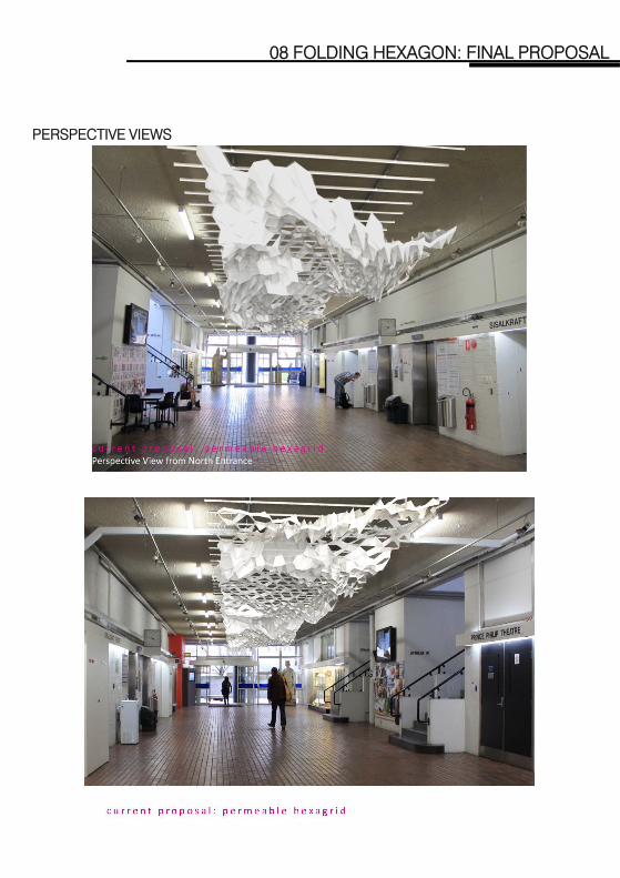
PERSPECTIVE VIEWS
08 FOLDING HEXAGON: FINAL PROPOSAL
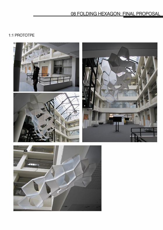
1:1 PROTOTPE
08 FOLDING HEXAGON: FINAL PROPOSAL
09 FINAL CEILING INSTALLATION

INTRODUCTION
09 FINAL CEILING INSTALLATION
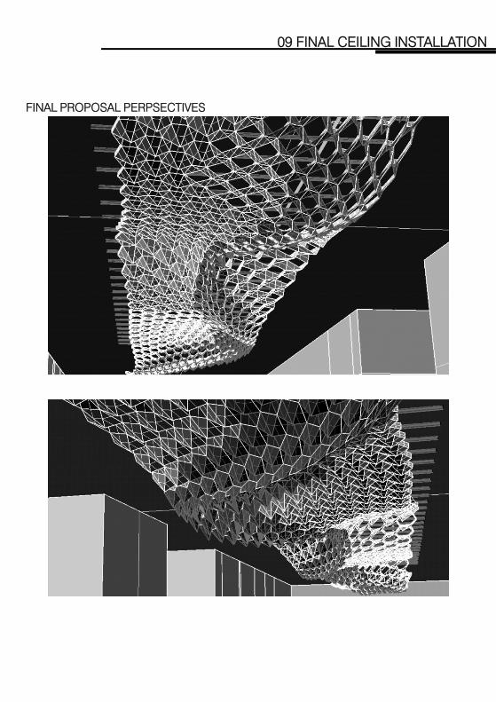
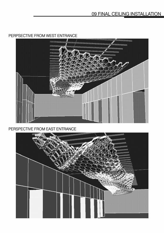
The proposed ceiling installation in the ground floor foyer of the ABP Faculty Building and secondly, the functions of the concourse as a circulation route as well as a gathering space. The overall form is derived from a study of stationary and moving bodies within the concourse: the common gathering spaced create peaks in the undulating surface, while a circulation path is carved in between these spaces as the troughs of the form. The modules create large permeable openings at
h i h d i ( h h i ll h gathering spaces that correspond to main entry ways (such as the stairwell, the elevator, etc), while large overlapping, enclosed gestures are created at independent gathering spaces (e.g. near exhibition shelves). The modules in between slowly shift from being more open, to more enclosed, and vice versa, creating a controlled rate of change in the permeability of the skin.

09 FINAL CEILING INSTALLATION
FINAL PROPOSAL PLAN
FINAL PROPOSAL DIAGRAMMATIC SECTION
09 FINAL CEILING INSTALLATION
FINAL PROPOSAL PERPSECTIVES
09 FINAL CEILING INSTALLATION
PERPSECTIVE FROM WEST ENTRANCE
PERSPECTIVE FROM EAST ENTRANCE
09 FINAL CEILING INSTALLATION
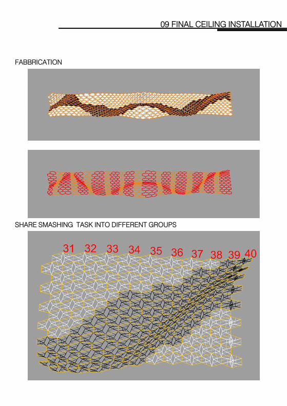
FABBRICATION
SHARE SMASHING TASK INTO DIFFERENT GROUPS

09 FINAL CEILING INSTALLATION
SMASHING MODULES
RELOCATE SURFACES FORMING FLAPS & RINGS

09 FINAL CEILING INSTALLATION
LAYOUT & NESTING
SUSPENSION CABLES & FISHING WIRE REINFORCEMENT
09 FINAL CEILING INSTALLATION
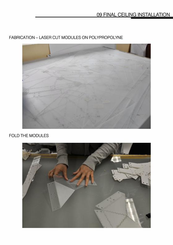
FABRICATION – LASER CUT MODULES ON POLYPROPOLYNE
FOLD THE MODULES

09 FINAL CEILING INSTALLATION
FOLD THE RINGS
BULL CLIPS TO HOLD THE MOLDULES INPLACE
09 FINAL CEILING INSTALLATION
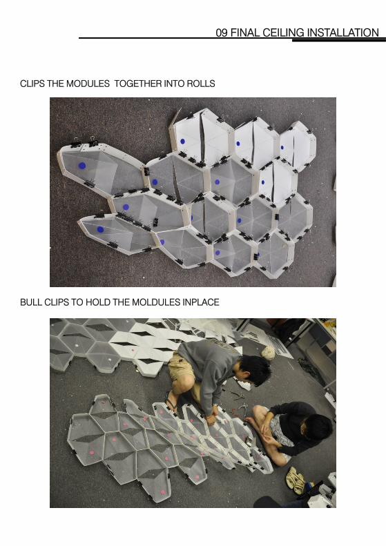
CLIPS THE MODULES TOGETHER INTO ROLLS
BULL CLIPS TO HOLD THE MOLDULES INPLACE
09 FINAL CEILING INSTALLATION
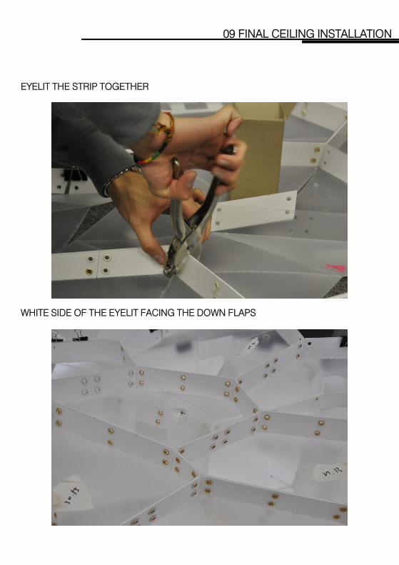
EYELIT THE STRIP TOGETHER
WHITE SIDE OF THE EYELIT FACING THE DOWN FLAPS

09 FINAL CEILING INSTALLATION
TIE REINFORCING FISHING WIRE
LENGTH ACCORDING TO RHINO FILE

09 FINAL CEILING INSTALLATION
PREFEBRICATION OF CABLES
ATTACH CABLES ON PREFABRICATED STRIPS

09 FINAL CEILING INSTALLATION
TEST HANGING OF PROTOTYPE
5/F PREFEBRICATION WORKSHOP AREA
09 FINAL CEILING INSTALLATION
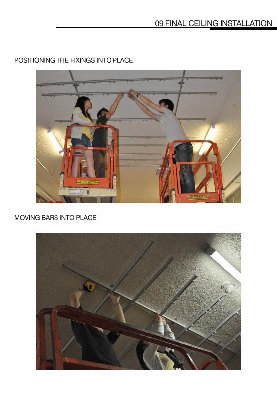
POSITIONING THE FIXINGS INTO PLACE
MOVING BARS INTO PLACE

09 FINAL CEILING INSTALLATION
MOVING STRIPS TO G./F & JOIN 2 STRIPS TOGETHER
MOVE THE PIECE ON SISSOR LIFT

09 FINAL CEILING INSTALLATION
HANGING THE FIRST PIECE
EYELIT THE NEXT PIECE ON SISSOR LIFT

09 FINAL CEILING INSTALLATION
PERSPECTIVE VIEWS
CLOSE UP

09 FINAL CEILING INSTALLATION
VIEW FROM SOUTH ENTRANCE

09 FINAL CEILING INSTALLATION
VIEW FROM SOUTH ENTRANCE

MASTER DESIGN STUDIO
Recommended