Latest Development in Ring Frame
The ring frame has under gone significant changes. One of the most innovative developments that have been incorporated on this machine is
compact spinning, which is discussed as a separate lecture in the next module. The other significant modern development will beare discussed
further.
Tackling spindle under windings Rieter SERVOgrip
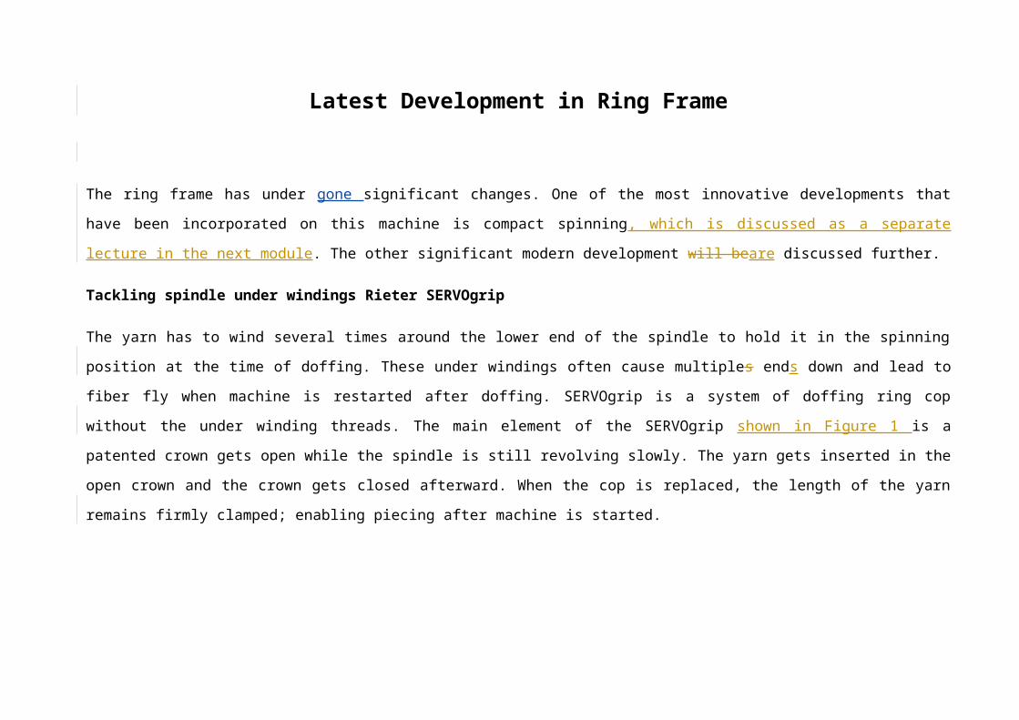
The yarn has to wind several times around the lower end of the spindle to hold it in the spinning position at the time of doffing. These under
windings often cause multiples ends down and lead to fiber fly when machine is restarted after doffing. SERVOgrip is a system of doffing ring cop
without the under winding threads. The main element of the SERVOgrip shown in Figure 1 is a patented crown gets open while the spindle is still
revolving slowly. The yarn gets inserted in the open crown and the crown gets closed afterward. When the cop is replaced, the length of the yarn
remains firmly clamped; enabling piecing after machine is started.
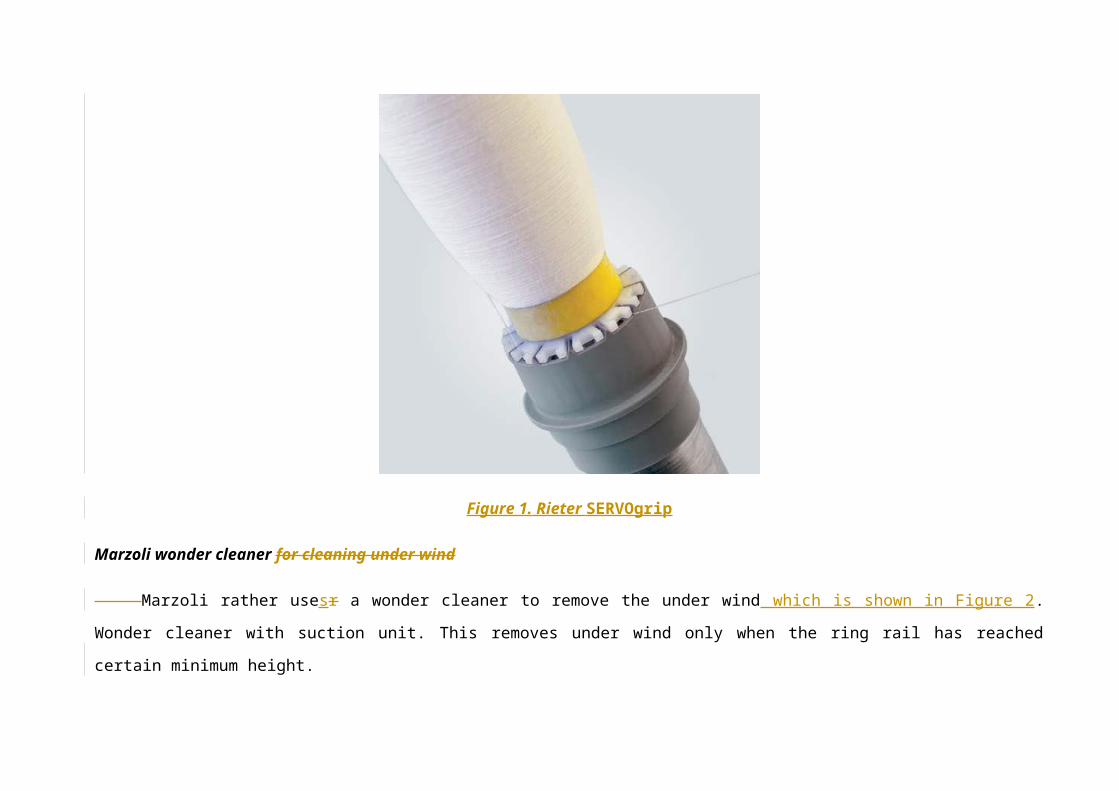
Figure 1. Rieter SERVOgrip
Marzoli wonder cleaner for cleaning under wind
Marzoli rather usesr a wonder cleaner to remove the under wind which is shown in Figure 2. Wonder cleaner with suction unit. This removes
under wind only when the ring rail has reached certain minimum height.
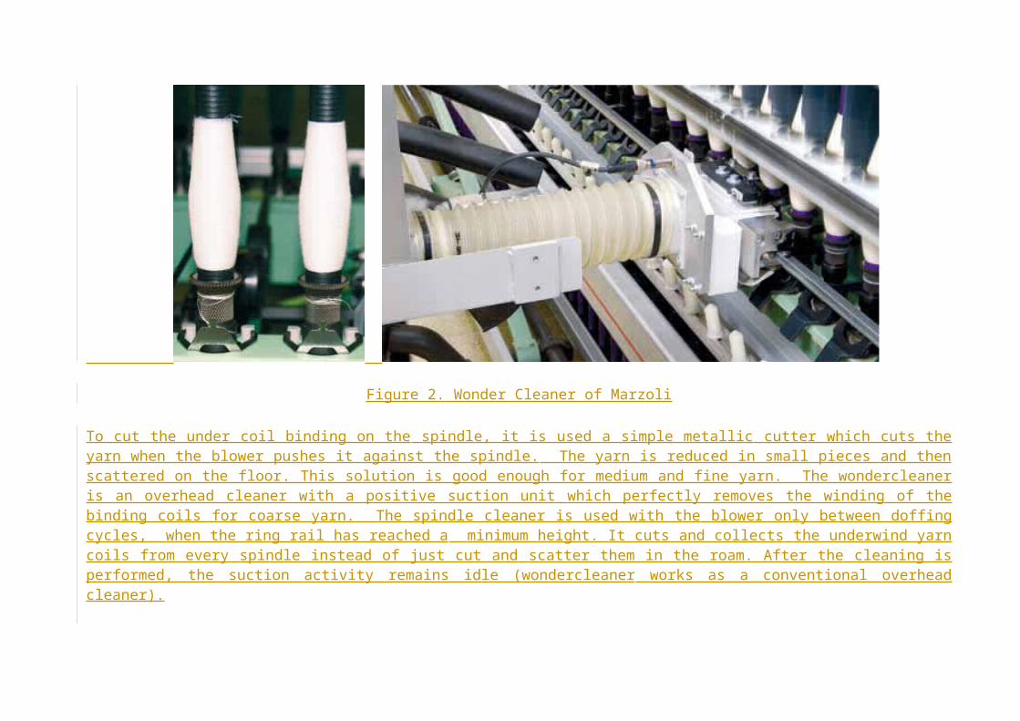
Figure 2. Wonder Cleaner of Marzoli
To cut the under coil binding on the spindle, it is used a simple metallic cutter which cuts the yarn when the blower pushes it against the spindle. The yarn is reduced in small pieces and then scattered on the floor. This solution is good enough for medium and fine yarn. The wondercleaner is an overhead cleaner with a positive suction unit which perfectly removes the winding of the binding coils for coarse yarn. The spindle cleaner is used with the blower only between doffing cycles, when the ring rail has reached a minimum height. It cuts and collects the underwind yarn coils from every spindle instead of just cut and scatter them in the roam. After the cleaning is performed, the suction activity remains idle (wondercleaner works as a conventional overhead cleaner).
Changes in Spinning geometry and drafting components Zinser optimized spinning geometry
Zinser has claimed that the yard has been made short, thus causes fewer disturbances to twist transmission as compared with a long thread
run. Then programme controlled motor gives to yarn guiding element consequently bobbin build can also be pre-programmed from the control
panel by setting winding length, traverse length, and ring rail upward displacement. The traversing yarn guide remains at standstill at the start of the
bobbin build operation for effective adaptation to spinning tension. That results in to constant yarn tension.
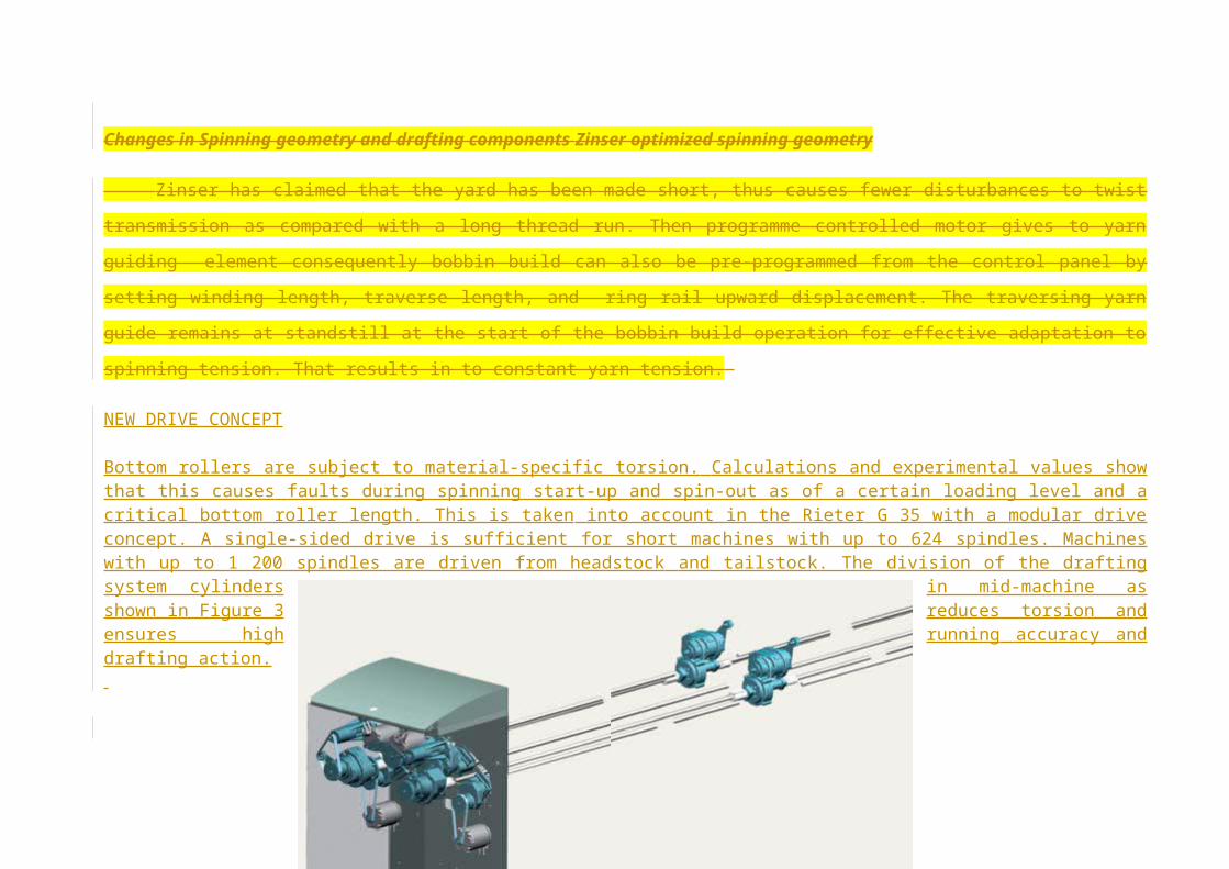
NEW DRIVE CONCEPT
Bottom rollers are subject to material-specific torsion. Calculations and experimental values show that this causes faults during spinning start-up and spin-out as of a certain loading level and a critical bottom roller length. This is taken into account in the Rieter G 35 with a modular drive concept. A single-sided drive is sufficient for short machines with up to 624 spindles. Machines with up to 1 200 spindles are driven from headstock and tailstock. The division of the drafting system cylinders in mid-machine as shown in Figure 3 reduces torsion and ensures high running accuracy and drafting action.
Figure 3 New Drive System of Rieter for Drafting Rollers
Toyota optimizes spinning geometry
The reduction in stretch length and higher spinning angle on Toyota RX240 New ring frame results into higher-speed due to better twist propagation
and stable ballooning with reduced yarn breakage. Similarly balloon control ring that moves together with the lappet at the start of winding and then
with the ring from about 40% cop winding leads to stable balloon form.
Marzoli different winding geometry for different tube length
Similarly, depending upon the tube length, the spinning angle on Marzoli MPN ring frame is optimized for better running condition. The distance
between the BC ring, delivery angle, lappet and ring rail has been also optimized.
Suessen ACP cradle and top roller loading via, spring plate
As a basic principle, each of the two pairs of rollers in a drafting zone produces a zone of fibre friction by pressure. The fibre condensation caused by this pressure does not only have a vertical effect, but spreads from both sides into the fibre strand (Figure 4). Both fields of friction are finally responsible for fibre guidance and the extent of regularity produced by the drafting process. The two fields of friction should not overlap, nor should their spheres of activity be too far apart.
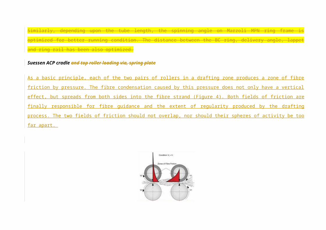
Figure 4. Pressure Fields in Roller Drafting
It is beneficial to the draft and degree of regularity achievable, if within a drafting zone the field of friction of the back roller pair reaches as far as possible into the drafting zone to guide the fibres as long as possible. The front field of friction should be short and strong so that only the clamped fibres are drawn out of the fibre strand. This ideal is however restricted by relatively close limits in design as a result of the geometrical conditions.
The high degree of parallelism of the fibres achieved by the preceding steps of drawing, doubling and imparting of twist on the roving frame has in turn the effect that the inter-fibre friction at the cradle clamping line is still high. The drafting force therefore rises considerably at first. It reaches its maximum when the first fibres start to move and static friction turns into kinetic friction.
This process takes place in the main draft zone between the two aprons. As soon as all fibres are moving, the drafting force is decreasing again considerably. This condition is reached in the front area of both aprons up to the clamping line of the front roller pair. Inter-fibre friction is very low in this area (Figure 5).
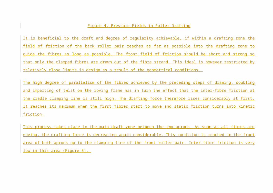
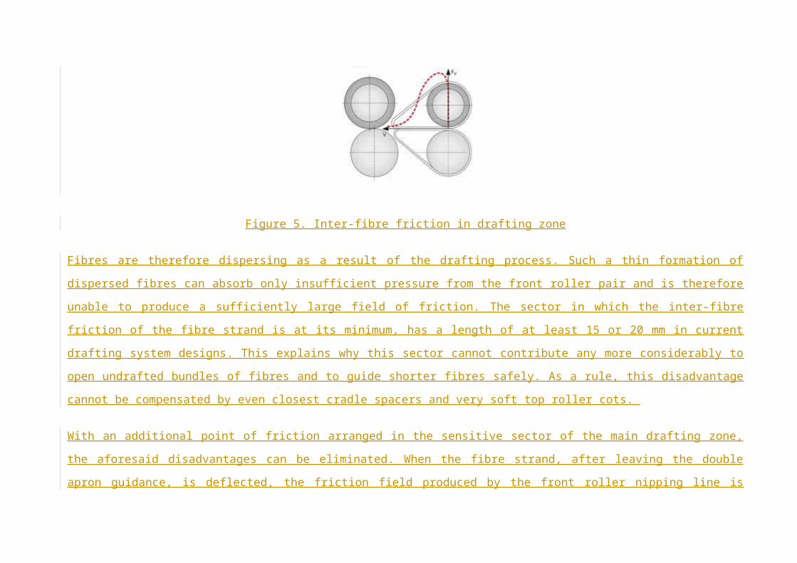
Figure 5. Inter-fibre friction in drafting zone
Fibres are therefore dispersing as a result of the drafting process. Such a thin formation of dispersed fibres can absorb only insufficient pressure from the front roller pair and is therefore unable to produce a sufficiently large field of friction. The sector in which the inter-fibre friction of the fibre strand is at its minimum, has a length of at least 15 or 20 mm in current drafting system designs. This explains why this sector cannot contribute any more considerably to open undrafted bundles of fibres and to guide shorter fibres safely. As a rule, this disadvantage cannot be compensated by even closest cradle spacers and very soft top roller cots.
With an additional point of friction arranged in the sensitive sector of the main drafting zone, the aforesaid disadvantages can be eliminated. When the fibre strand, after leaving the double apron guidance, is deflected, the friction field produced by the front roller nipping line is increased and shifted in direction of the cradle opening. Fibre orientation and extension are improved. Parallel fibres still adhering to each other (fibre packages) can now be shifted relatively to each other even in this sector. Consequently, drafting defects are reduced, and the overall regularity of
the drafting process is improved. At the same time, the tendency of the fibre strand to spread is suppressed. Inter-fibre contact is increased, and finally this results in a better utilisation of fibre substance and better yarn strength.
By shifting the front field of friction towards the cradle opening, the apron nip can be closer. For this reason, the correct cradle design is important for the interplay with the point of friction. Numerous trials have confirmed again and again that a cradle with flexible leading edge is of advantage in the combination with the bottom apron nose bars offered today, most of which have a steplike design. Such a cradle compensates the practically unavoidable length tolerance of aprons and permits closest apron nips without the dreaded stick-slip movements of the aprons.
A vast amount of trials was required to define the correct position of the friction point in relation to the flexible leading edge of the cradle and to translate this solution into technical design (diameter, coefficient of friction of the surface). It had to be ensured in particular that for all yarn counts both fields of friction can be shifted as closely as possible towards each other without direct contact.
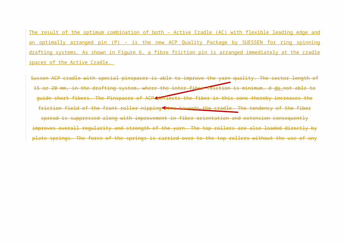
The result of the optimum combination of both – Active Cradle (AC) with flexible leading edge and an optimally arranged pin (P) – is the new ACP Quality Package by SUESSEN for ring spinning drafting systems. As shown in Figure 6, a fibre friction pin is arranged immediately at the cradle spacer of the Active Cradle.
Sussen ACP cradle with special pinspacer is able to improve the yarn quality. The sector length of 15 or 20 mm, in the drafting system, where the
inter-fiber friction is minimum, d do not able to guide short fibers. The Pinspacer of ACP deflects the fiber in this zone thereby increases the friction
field of the front roller nipping line towards the cradle. The tendency of the fiber spread is suppressed along with improvement in fiber orientation
and extension consequently improves overall regularity and strength of the yarn. The top rollers are also loaded directly by plate springs. The force
of the springs is carried over to the top rollers without the use of any moving part and therefore involves friction. The pre-tension of the spring can
be changed by a cam at the front weighting unit to adjust the load.
Figure 6. ACP Quality Package by SUESSEN
Monitoring system Rieter Individual Spindle Monitoring (ISM)
Individual Spindle Monitoring is a quality monitoring system. This system reports faults and anomalies by means of a 3-level light guidance system
thus enable personnel to locate the problem spindles without unnecessary searches. Signal lamps at the end of the machine indicate the side of the
machine on which ends down rate has been exceeded (level 1). An extra-bright LED on each section guides the operator to the location of the fault
(level 2). The indicator on the spindle itself signals ends down with a continuous light and slipping spindles with a flashing light (Level 3).
This system features an optical sensor on the ring frame at each spinning position, which monitors the motion of the traveler. It can therefore perform 3 operations:
recording ends down (incl. startup ends down following cop changes) and registering spindles rotating too slowly (so-called slipper spindles) convenient analysis and presentation of these data in the SPIDERweb system operator guidance in 3 steps:
o signal lamps at both ends of the machine indicate when an ends down limit has been exceeded o a LED for each 24 spindles indicates that an end is down in this section o a LED at each spinning position indicates an end down or a slipper spindle.
This individual spindle monitoring system has distinct advantages:
no moving parts no maintenance continuous monitoring of all spindles.
Zinser Guard System (Roving guard and FilaGuard)
The individual yarn monitor FilaGuard monitors the rotation of the steel ring traveller on each spindle and detects any yarn break immediately.
Optical signals indicate the specific yarn break, directing the operating personnel to the spindle of yarn break to rectify the problem. The automatic
roving stop RovingGuard, which responses within milliseconds, interrupts the roving feed in case of yarn break thereby prevents material loss and
minimise lapping tendancy.
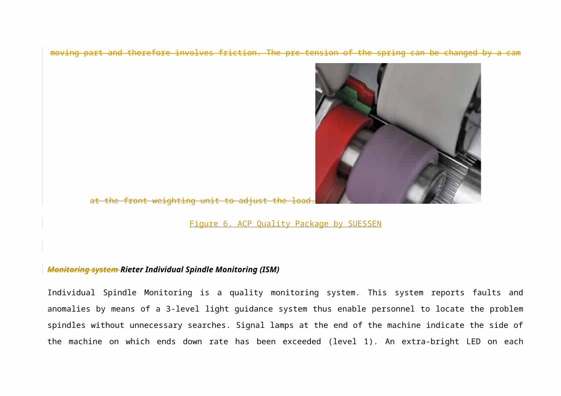
Figure 7. Filaguard monitors in Zinser Ring Frame
Multi-motor drive system
Rieter FLEXIdraft
FLEXIdraft flexible drive, eqipped on Rieter G33 ring spinning machine, features separate drives for the drafting system and the spindles. All three bottom rollers of the drafting system are frequencycontrolled and individually driven by synchronous motors. This system enables change in the yarn count, twist and twist direction (S/Z) via, the control panel of the machine. The drafting rollers are split in the centre of the machine to ensure smooth running of drafting operation. On the basis of FLEXIdraft, each drafting system drive can be started or stopped individually via, FLEXIstart system. Thus depending on the machine length, 1-sided or 2 sided drafting system drives are used. FLEXIdraft has a further advantage of noise level reduction due to elimination gear wheels.

Zinser SynchroDrive, SynchroDraft and ServoDraft
Zinse SynchroDrive is a multi-motor tangential belt drive
system. The system employed several motors arranged at
defined positions to drive spindles through tangential belt. The
consistency in spindles speed relative each other
minimizes the twist variation apart from reduction in
noise level and minimum power requirement. SynchroDraft
transmission is for long machines to drive the middle
bottom rollers from both ends, consequently minimizes twist
variation between gear end and off end of the
machine. Zinser ServoDraft system employs
individual motors for driving bottom rollers of the
drafting system. Hence yarn count and twist change can be
done by simply feeding required parameters at the control
paner of the machine that adjust the motors speed accordingly.
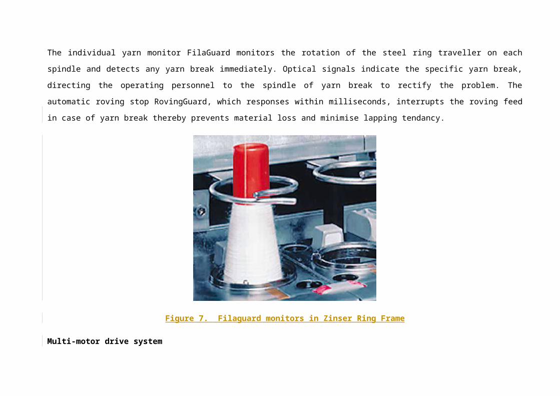
Figure 8. Zinser Modern Ring Frame Drive System
Zinser SynchroDrive is a multi-motor tangential belt drive system as shown in Figure 8. The system employed several motors arranged at defined
positions to drive spindles through tangential belt. The consistency in spindles speed relative each other minimizes the twist variation apart from
reduction in noise level and minimum power requirement. SynchroDraft transmission is for long machines to drive the middle bottom rollers from
both ends, consequently minimizes twist variation between gear end and off end of the machine. Zinser ServoDraft system employs individual
motors for driving bottom rollers of the drafting system. Hence yarn count and twist change can be done by simply feeding required parameters at
the control paner of the machine that adjust the motors speed accordingly.
Zinser OptiStep and OptiStart
OptiStep is a system of adjusting spindle speed in 10 different ranges through out the cop build on Zinser ring spinning machines. The start-up, tip
and main spinning speeds can be defined with a 10 point speed curve. Similarly OptiStart (optional) is a running-in programme for ring travellers to
perform the running-in phases of the ring travellers with precise accuracy up to production speed. Hence the traveller service life is substantially
extended.
Zinser OptiMove
Zinser uses separate electric roving guide drive OptiMove to traverse the roving guide. This is claimed that top rollers wear is reduced and service
life is increased significantly. The roving guide drive can be easily set using inductive proximity switches.
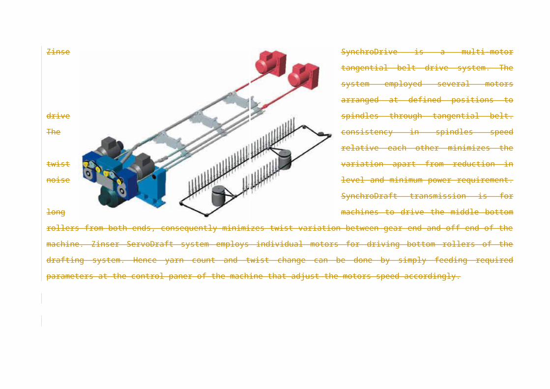
Figure 9. Zinser OptiMove for Roving Guide Traverse
Zinser uses separate electric roving guide drive OptiMove to traverse the roving guide. This is claimed that top rollers wear is reduced and service
life is increased significantly. The roving guide drive can be easily set using inductive proximity switches.
Toyota ElectroDraft System
The Toyota ElectroDraft system (optional) features independence servo motors drive for front and back rollers. The spindles are also driven by
separate tangential drive system where one motor drives 96 spindles. Thus the required draft and yarn twist can be set via, control panel.
Toyota Servo motor-driven positive lifting mechanism

Toyota’s proprietary crew shaft positive lifting mechanism is used to on RX240 New ring rail lifting motion. This eliminates disparity in the ring
rail motion during long periods of continuous operation. The different cop parameters like chase length, cop diameter, winding start position, bobbin
diameter (bottom and top), total lift, etc, can be fed via, key operation of the machine panel.
Zinser OptiStep and OptiStart
OptiStep is a system of adjusting spindle speed in 10 different ranges through out the cop build on Zinser ring spinning machines. The start-up, tip
and main spinning speeds can be defined with a 10 point speed curve. Similarly OptiStart (optional) is a running-in programme for ring travellers to
perform the running-in phases of the ring travellers with precise accuracy up to production speed. Hence the traveller service life is substantially
extended.
Zinser OptiMove
Zinser uses separate electric roving guide drive OptiMove to traverse the roving guide. This is claimed that top rollers wear is reduced and service
life is increased significantly. The roving guide drive can be easily set using inductive proximity switches.
Marzoli twin traverse method
A double traverse motion for the roving guide used by Marzoli covers the wider area over the cots and the apron life.
Recommended