Setting up the Polycom® HDX™ Ceiling Microphone Array Series
1725-27017-002/A
©2007, Polycom, Inc. All rights reserved. Polycom® and the Polycom logo are registered trademarks and HDX™, SoundStructure™, and TPX™ are trademarks of Polycom, Inc.
November 2007
Before you begin, make sure that your ceiling can support up to 2 lbs (.9 kg).
If you are setting up a Polycom HDX Ceiling Microphone Array with a Polycom HDXSystem or a Polycom SoundStructure™ C-Series System, begin on page 2.
If you are setting up a Polycom HDX Ceiling Microphone Array Extension Kit with a Polycom HDX System or a Polycom SoundStructure C-Series System, begin on page 12.
If you are setting up a Polycom TPX™ HD 306M System, install the first Ceiling Microphone Array by beginning on page 2, and install the second Ceiling Microphone Array by beginning on page 12.

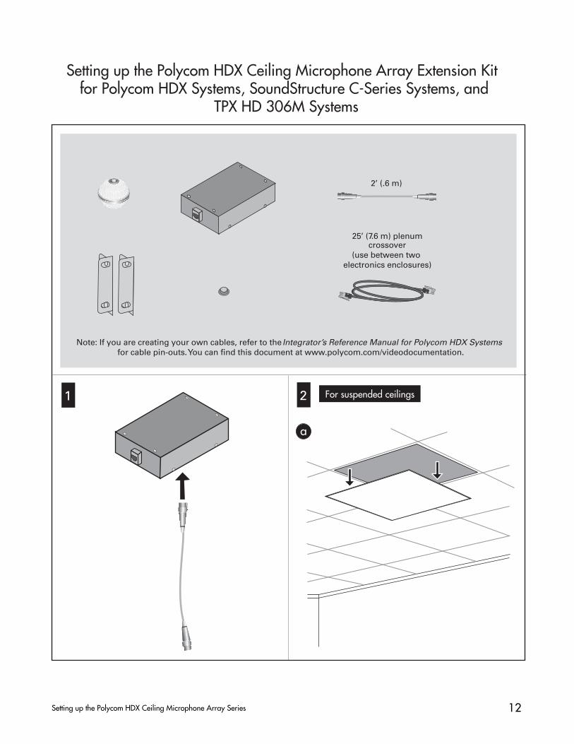
For suspended ceilings
2Setting up the Polycom HDX Ceiling Microphone Array Series
1 2
a
10’ (3.1 m) non-plenumstraight-through
(use between wall plate and codec only; do not use for any
other application)
50’ (15.2 m) plenumcrossover
(use between electronics enclosure and codec, between electronics enclosure and wall
plate, or between two electronics enclosures)
Note: If you are creating your own cables, refer to the Integrator’s Reference Manual for Polycom HDX Systems for cable pin-outs. You can find this document at www.polycom.com/videodocumentation.
Setting up the Polycom HDX Ceiling Microphone Array for Polycom HDX Systems, SoundStructure C-Series Systems, and TPX HD 306M Systems
2’ (.6 m) 18” (.5 m) RJ-45 toWalta connector adapter

3Setting up the Polycom HDX Ceiling Microphone Array Series
For suspended ceilings
b c
d eOptional Optional
.75” (1.9 cm)
For added safety when removing the ceiling tile at a later time, securely attach the electronics enclosure to the ceiling supports using suitable wire or other hardware appropriate for your ceiling type and in accordance with local regulations. Be sure that the length of wire you use to secure the electronics enclosure is short enough to prevent the enclosure from striking the person removing the ceiling tile.
2 (cont.)

4Setting up the Polycom HDX Ceiling Microphone Array Series
3 For ceilings that are not suspended
4
b
a
a
1.625”(4.13 cm)
.25”(.64 cm) 1.614”(4.10 cm)
1.614”(4.10 cm) .25”(.64 cm)
For suspended ceilings
For suspended ceilings
f
2 (cont.)
To attach the electronics en-closure, use suitable hard-ware for your ceiling type. Align the enclosure so that, when the Microphone Array is attached, the dot on the Microphone Array points towards the main display as shown in step 7.

5Setting up the Polycom HDX Ceiling Microphone Array Series
For suspended ceilings4 (cont.)
c
50’ (15.2 m)
For Polycom HDX Systemsb
~ 10’(3.1 m)
SoundStructure C16TM
50’ (15.2 m)
~ 10’(3.1 m)
c For Polycom SoundStructure C-Series Systems(cont.)

6Setting up the Polycom HDX Ceiling Microphone Array Series
For suspended ceilings4 (cont.)
d
c
50’ (15.2 m)
~ 10’(3.1 m)
For Polycom TPX HD 306M Systems(cont.)
For Polycom TPX HD 306M Systems, you must position the two Ceiling Microphone Arrays relative to the multipurpose table. Therefore, before installing the first Ceiling Microphone Array, you must use the measurements at the right to determine the placement of the creden-za and the multipurpose table in your room.
When determining the placement of the Ceiling Microphone Arrays, you must ensure that:
The left Ceiling Microphone Array will be 2 ft (61 cm) to 3 ft (91 cm) to the left of the vertical centerline of the multipurpose table, and will be no more than 6 in (15 cm) from the horizontal centerline of the multipurpose table.The right Ceiling Microphone Array will be 2 ft (61 cm) to 3 ft (91 cm) to the right of the vertical centerline of the multipurpose table, and will be no more than 6 inches (15 cm) from the horizontal centerline of the multi-purpose table.
190.2”
483.1cm
274.3cm
108.0”
10.2cm
4.0”
121.8”
309.4cm
72.4cm
28.5”
Minimum
room size
396.2cm
156.0”
216.0”
548.6cm
Each X in the illustration above shows approximatelywhere the Ceiling Microphone Arrays should be placed.
c For Polycom TPX HD 306M Systems(cont.)
CL
CL X X

7Setting up the Polycom HDX Ceiling Microphone Array Series
e (cont.)
44V
CR
/DV
D
3
VC
R/D
VD
3
AU
X
4 (cont.)
SoundStructureC-Series Systems
10’ (3.1 m)
PIN 2: TXD
PIN 3: RXD
PIN 5: GROUND
PIN 7: CTS
PIN 8: RTS
LAN C-LINK2 OBAM IR
RS-232
REMOTE CONTROL 2IN OUT
1 2 3 4 5 6 7 8 9 10 11 12 13 14 15 16
1 2 3 4 5 6 7 8 9 10 11 12 13 14 15 16
OU
TP
UT
SIN
PU
TS
SoundStructure C16TM
12V
REMOTE CONTROL 1
C-LINK2
SoundStructure C16TM
10’ (3.1 m)
For Polycom HDX 4000 Systems For Polycom SoundStructure C-Series Systems
10’ (3.1 m)
e
10’ (3.1 m)
HDX 9000 Systems
For Polycom HDX 9000 Systems For Polycom HDX 8000 Systems
100-240VAC
50/60Hz 2.3A
For suspended ceilings
RJ-45
adapter
to Walta connector
RJ-45
adapter
to Walta connector
HDX 8000Systems
HDX 4000Systems

8Setting up the Polycom HDX Ceiling Microphone Array Series
10’ (3.1 m)
4 (cont.) For suspended ceilings
Primary (center)codec in credenza
For more information, refer to the Polycom TPX HD 306M Installation Guide.
or patch panel on sideof credenza
Refer to step4c on page 6for information about Ceiling Microphone Array placement.
5 For ceilings that are not suspended
50’ (15.2 m)
a
SoundStructure C16TM
50’ (15.2 m)
For Polycom HDX Systems
~ 10’(3.1 m)
~ 10’(3.1 m)
For Polycom TPX HD 306M Systemse (cont.)
a (cont.) For Polycom SoundStructure C-SeriesSystems
For Polycom TPX HD 306M Systems
50’ (15.2 m)
~ 10’(3.1 m)

9Setting up the Polycom HDX Ceiling Microphone Array Series
RJ-45
adapter
to Walta connector
For Polycom HDX 8000 Systems44
VC
R/D
VD
3
VC
R/D
VD
3
AU
X
HDX 8000Systems
SoundStructure C16TM
SoundStructureC-Series Systems
PIN 2: TXD
PIN 3: RXD
PIN 5: GROUND
PIN 7: CTS
PIN 8: RTS
LAN C-LINK2 OBAM IR
RS-232
REMOTE CONTROL 2IN OUT
1 2 3 4 5 6 7 8 9 10 11 12 13 14 15 16
1 2 3 4 5 6 7 8 9 10 11 12 13 14 15 16
OU
TP
UT
SIN
PU
TS
SoundStructure C16TM
12V
REMOTE CONTROL 1
For Polycom SoundStructure C-Series Systems
C-LINK2
For Polycom HDX 4000 Systems
b
5 (cont.) For ceilings that are not suspended
RJ-45
adapter
to Walta connector
100-240VAC
50/60Hz 2.3A
HDX 4000Systems
b (cont.)
HDX 9000 Systems
For Polycom HDX 9000 Systems

10Setting up the Polycom HDX Ceiling Microphone Array Series
6
For Polycom TPX HD 306M Systemsb (cont.)
5 (cont.) For ceilings that are not suspended
8
For Polycom HDX Systems and for SoundStructure C-SeriesSystems that are being used with a video conferencing system: You must point the dot (located on the band around the middle of the microphone ball) towards the main display.
For Polycom SoundStructure C-Series Systems that are notbeing used with a video conferencing system and for TPX HD306M Systems: You must point the dot (located on the band around the middle of the microphone ball) towards the front of the room.
7
These systems...Support up to this
many Ceiling
Polycom HDX 9000 Series
Polycom HDX 8000 Series
Polycom HDX 4000 Series
Polycom SoundStructure C12 and C16
Four
Three
Three
Four
Polycom SoundStructure C8
Two
Primary (center)codec in credenza
or patch panel on sideof credenza
Microphone Arrays...
For more information, refer to the Polycom TPX HD 306M Installation Guide.
11Setting up the Polycom HDX Ceiling Microphone Array Series
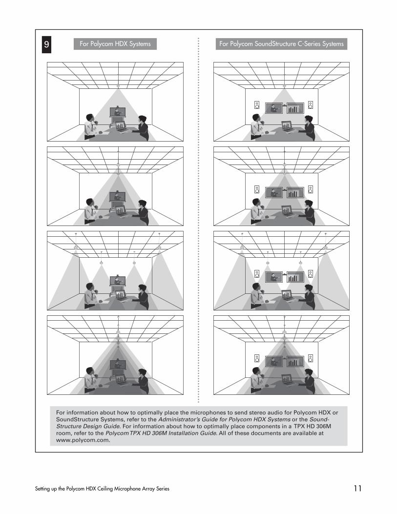
9 For Polycom HDX Systems For Polycom SoundStructure C-Series Systems
For information about how to optimally place the microphones to send stereo audio for Polycom HDX or SoundStructure Systems, refer to the Administrator’s Guide for Polycom HDX Systems or the Sound-Structure Design Guide. For information about how to optimally place components in a TPX HD 306Mroom, refer to the Polycom TPX HD 306M Installation Guide. All of these documents are available at www.polycom.com.
For suspended ceilings
12Setting up the Polycom HDX Ceiling Microphone Array Series
1 2
a
2’ (.6 m)
Setting up the Polycom HDX Ceiling Microphone Array Extension Kit for Polycom HDX Systems, SoundStructure C-Series Systems, and
TPX HD 306M Systems
25’ (7.6 m) plenumcrossover
(use between two electronics enclosures)
Note: If you are creating your own cables, refer to the Integrator’s Reference Manual for Polycom HDX Systems for cable pin-outs. You can find this document at www.polycom.com/videodocumentation.

13Setting up the Polycom HDX Ceiling Microphone Array Series
For suspended ceilings
b c
d eOptional Optional
.75” (1.9 cm)
For added safety when removing the ceiling tile at a later time, securely attach the electronics enclosure to the ceiling supports using suitable wire or other hardware appropriate for your ceiling type and in accordance with local regulations. Be sure that the length of wire you use to secure the electronics enclosure is short enough to prevent the enclosure from striking the person removing the ceiling tile.
2 (cont.)

14Setting up the Polycom HDX Ceiling Microphone Array Series
3 For ceilings that are not suspended
ba
For suspended ceilings
f
2 (cont.)
To attach the electronics en-closure, use suitable hard-ware for your ceiling type. Align the enclosure so that, when the Microphone Array is attached, the dot on the Microphone Array points towards the main display as shown in step 6.

15Setting up the Polycom HDX Ceiling Microphone Array Series
4
25’ (7.6 m)
5
(Do not use the non-plenum straight-through 10 ‘ (3.1 m) cable)
For Polycom HDX Systems and for SoundStructure C-SeriesSystems that are being used with a video conferencing system: You must point the dot (located on the band around the middle of the microphone ball) towards the main display.
For Polycom SoundStructure C-Series Systems that are notbeing used with a video conferencing system and for TPX HD306M Systems: You must point the dot (located on the band around the middle of the microphone ball) towards the front of the room.
6
For Polycom TPX HD 306M Systems
IMPORTANT: For TPX HD 306M installations, the Ceiling Microphone Arrays must be cabled as follows:Use the 25 ft (7.6 m) cable to connect the Ceiling Microphone Array on the left (when facing the credenza) to the Ceiling Microphone Array on the right. Use the 50 ft (15.2 m) cable to connect the Ceiling Microphone Array on the right to the codec.
25’ (7.6 m)
(Do not use the non-plenum straight-through 10 ‘ (3.1 m) cable)
For Polycom HDX Systems and SoundStructure C-Series Systems

16Setting up the Polycom HDX Ceiling Microphone Array Series
7 For Polycom HDX Systems For Polycom SoundStructure C-Series Systems
For information about how to optimally place the microphones to send stereo audio for Polycom HDX or SoundStructure Systems, refer to the Administrator’s Guide for Polycom HDX Systems or the Sound-Structure Design Guide. For information about how to optimally place components in a TPX HD 306M room, refer to the Polycom TPX HD 306M Installation Guide. All of these documents are available at www.polycom.com.
Recommended