CONTINUUM ® PUMPSHelical rotor pumps for high pressure and low noise application
Pompe a rotori elicoidali per applicazioni ad alta pressione e basso rumore
Patents GarantedBrevetti approvati
Continuum® Product LineContinuum® Product Line
CONTINUUM® PROJECT PROGETTO CONTINUUM®
2
Sustainable PowerIn a ever increasing demand for power, designers and manufacturers ofhydraulic devices have explored all opportunities to contain noise andreduce ripple. When System Life Cycle, Environmental Conditions, EnergyConsumption, and Performance are paramount the ultimate solution is tocut the problem at its root.
Noise is ExpensiveFrom small steering systems to large municipal equipment, from alubrication system to a forklift, noise is notonly generated by the pumps, but in mostcases the system generates noise byamplifying the ripple. Consequent pressuredrops are a noticeable energy consumer andreduce overall efficiency. Even in the mostdemanding conditions Continuum enablesthe system designer to focus on functionsand features, reducing customer frustrationby eliminating expensive enclosures, hosesand attenuators. Noise is relieved at theroot.
Power of SilenceOur product looks like the most popular ofhydraulic pumps, the Gear pump, but theirthe similarity ends. Continuum is set totransform the way end users perceivehydraulic devices. The ultimate solution forpreserving the experience of silence.Settima FM, introducing its new ContinuumProduct Line, is paving the way for Sustainable Fluid Power.
The Human FactorAs well as investing in the most advanced design and manufacturingcapability, Settima Flow Mechanisms base the quality of their value chainon the human factor. Encouraging innovation and personal responsibility,Settima has reached a high standard of quality and an extremely flexiblemanufacturing system.
The Continuum® PrincipleInvesting in innovation is about empowering impressive andrevolutionary ideas. Such as the one embraced by Continuum, a newpumps with continuous intermeshing, no-leaking rotors.
Technological innovation for HIGH pressure, LOW noise and LOWpulsationsThe Continuum® concept is based on three patented breakthroughs:O the rotors profileO the screw stepO the inner force balancing
Potenza sostenibilePer far fronte alla crescente domanda di potenza, progettisti e costruttoridi dispositivi idraulici hanno esplorato tutte le opportunità per contenereil rumore e ridurre le pulsazioni del circuito. Quando la durata della vitadel sistema, le condizioni ambientali, i consumi e le funzionalità sonofondamentali l’ultima soluzione è quella di tagliare il problema allaradice.
Il rumore é costosoDal piccolo sistema di sterzo all'ingombrante apparto della nettezza
urbana, dal sistema di lubrificazione alcarrello elevatore. Il rumore non solo ègenerato dalle pompe idrauliche, ma nellamaggior parte dei casi il sistema generarumore amplificando la pulsazione dipressione. Le perdite di carico conseguentisono un considerevole consumo di energiae sorgente di una inefficienza complessiva.Persino nelle condizioni più esigentiContinuum® abilita il progettista di sistemaad implementare nuove funzioni eproprietà non solo a ridurre la frustrazionedel cliente mediante costosi attenuatori,tubi flessibili e contenitori. Il Rumore e'rimosso alla radice.
Il potere del silenzioDotata delle dimensioni e flangiature deidispositivi idraulici più diffuse come lepompe ad ingranaggi, Continuum® èpronta a trasformare il modo in cui l'utentefinale percepisce il dispositivo idraulico. Lasoluzione definitive per preservarel'esperienza del silenzio. Settima FM,
introducendo la sua nuova linea di prodotti Continuum®, prepare la tradaper una Potenza Fluida Sostenibile.
Il fattore umanoAl di la' degli investimenti in capacita' di progettazione e produttiveSettima Flow Mechanisms e l'intera filiera produttiva basano la loroqualita' sul fattore umano. Incoraggiando l'innovazione e laresponsabilità personale, Settima FM ha raggiunto un alto standard diqualità e una produzione estremamente flessibile.
Il principio Continuum®
Investire in innovazione significa dare valore a idee rivoluzionarie. Cosìcome quella adottata da Continuum, una nuova pompa con rotori acontatto continuo e senza perdite.
Innovazione tecnologica per ALTA pressione, BASSO rumore e BASSEpulsazioni Il Concetto Continuum® e’ basato su tre innovazioni brevettate:O il profilo dei rotoriO il passo della viteO il bilanciamento delle forze interne

Continuum® Product Line
3
Pressure Ripple and Noise AnalysisThe current designs of high pressure gear pumps permit a quantity offluid to be trapped and compressed between the gear teeth with thefollowing consequences:O sharp changes in pressure growthO noise (increasing rapidly above 1500 rpm)
The continuum design concept achieves one main design objective:O total absence of trapped and compressed oil between the gears;O no trade-offs in material selection or treatment.
This results in: O smooth changes in pressure growthO HIGH EfficiencyO LOW noise (up to 5.000 rpm)
The pressure ripple laboratory test shows the impressive improvement ofthe pulsation in a Continuum® designed pump (pressure sampling at 100KHz) while maintaining excellent efficiency.The noise laboratory test shows the impressive improvement of the noisecurve in a Continuum® designed pump.
Analisi della pulsazione di pressione e del rumoreL’attuale struttura di pompe ad ingranaggi per alta pressione tipicamenteimplica camere di compressione del fluido tra denti delle ruote dentate. Conseguentemente si osservano:O rapide variazioni nella pressione O rumore (a partire da 1.500 rpm)
Il concetto di progettazione Continuum® consente un principale obiettivodi progettazione:O totale assenza di camere di alta pressione di olio compresso nell’ingranaggio;O nessun compromesso su selezione materiale e sui trattamenti degli stessi.
Questo implica: O smorzate variazioni di crescita di pressione O ALTE efficienze O BASSO rumore (fino a 5.000 rpm)
I test di Pulsazione della Pressione mostrano un miglioramentoimpressionante sulla pulsazione nelle pompe Continuum® (con pressionecampionata a 100KHz) pur mantenendo efficienze eccellenti. I test di laboratorio di rumore mostrano un significativo miglioramentodelle curve di rumore.
Models available / Modelli Disponibili GR28 - GR33 - GR38 - GR47 - GR55 - GR72
Flanges / Flange Group 1 - Group 2 (European, German, BKT, SAE-A) - Group 3 (European, SAE-B) Gruppo 1 - Gruppo 2 (Europeo, Tedesco, BKT, SAE-A) - Gruppo 3 (Europeo, SAE-B) ISO 3019/2 – IEC standard (per accoppiamento diretto)
Connections / Connessioni GAS - SAE 3/4’ 3000 PSI - FL 4 HOLES M6 SU Ø40 DN20 (***) / GAS – SAE 3⁄4’ 3000 PSI FL 4 HOLES M6 SU Ø40 DN20 (***)
Installation position / Posizione di installazione External, underoil / Esterna e immersa
Shaft rotation / Rotazione albero Clockwise / Destra (standard)
Shaft speed / Velocità di rotazione From 700 to 3.600 rpm (for GR72 to 2200RPM) / Da 700 a 3.600 rpm (per GR72 a 2200 RPM)
Displacements - Flows / Dislocamento – Flusso From 4 up to 200 cm3 - From 6L/min up to 300L/min (at 1.500 rpm) / Da 4 a 200 cm3 - Da 6L/min a 300L/min (a 1.500 rpm)
Operating pressure (*) / Pressione operativa (*) Continuous: 240 bar Cycle ON/OFF: 250 bar Peak: 280 bar
Inlet pressure / Porta di ingresso 0,8 - 2 bar (****) / 0,8 – 2 bar (****)
Fluids / Fluidi Mineral oil HLP e HLVP - Ecologic fluids HETG-HEPG-HEE - Synthetic fluid or emulsion: (**)HFA oil-water emulsion - (**)HFB water-oil emulsion - (**)HFDR phosphate ester
Viscosity / Viscosità Permissible (**): from 20 up to 800 mm2/s [cSt]Recommended: from 24 up to 150 mm2/s [cSt]Starting conditions (**): up to 3.000 mm2/s [cSt]
Environment temperature / Temperatura ambiente From -15° up to +60°C / Da -15° a +60°C
Hydraulic temperature / Temperatura idraulica From -15° up to +80°C / Da -15° a +80°C
Contamination Level / Livello di contaminazione From 10 NAS (21/9/15 ISO4406) to 8 NAS (18/17/14 ISO4406) for heavy duty operations (*****)Da 10 NAS (21/9/15 ISO4406) a 8 NAS (18/17/14 ISO4406) per operazioni pesanti (*****)
Filtration / Filtrazione Inlet Port: from 50 to 30 µm for heavy duty operations (*****) Outlet Port: from 25 to 10 µm for heavy duty operations (*****) / Porta d'ingresso: da 50 a 30 µm per operazioni pesanti (*****) Porta d'uscita: da 25 a 10 µm per operazioni pesanti (*****)
Seals / Guarnizioni NBR, FKM, FPM, EPDM - Special on request / NBR, FKM, FPM, EPDM – Speciali su richiesta
Noise / Rumore from 52 up to 63 dB(A) at 2.950 rpm - Value based on ISO 4412 test procedure / da 52 a 63 dB(A) a 2.950 rpm - Valore rilevato con procedura ISO 4412
Flanges / Flange Cast Iron / Ghisa
Pump body (standard) / Corpo pompa (standard) Extruded aluminium alloy / Alluminio estruso
Screw / Viti Case hardened grinded steel / Acciaio temperato
Maintenance / Manutenzione No / Nessuna
Detailed technical information / Informazioni tecniche dettagliate
Olii minerali HLP e HLVP - Fluidi ecologici HETG - HEPG - HEEFluidi sintetici o emulsioni: (**) HFA emulsione acqua-olio – (**)HFB emulsione acqua-olio – (**)HFDR estere fosfato
Continuo: 240 bar Ciclo ON/OFF: 250 bar Picco: 280 bar
Consentita (**): da 20 a 800 mm2/s [cSt] Raccomandata: da 24 a 150 mm2/s [cSt] Condizioni di avviamento (**): fino a 3.000 mm2/s [cSt]
(*) Test executed with Oil ISO VG46 (40°C) – 10µm filtration - (**) Please contact the company to have further details - (***) Available on certain models upon customer request(****) Up to 10 bar Shaft Seal available on certain models upon request - (*****) Heavy Duty operation are defined as above 150bar , more than 4h/day, more than 100 cycle/day, oil ISO 46
(*) Test eseguito con Olio ISO VG46 (40°C) - filtrazione a 10µm - (**) Per maggiori dettagli contatta i nostri uffici - (***) Disponibile su alcuni modelli su richiesta(****) Anello di tenuta dell'alberofino a 10 bar disponibili su alcuni modelli - (*****) Operazioni Pesanti sono definite come sopra 150bar , piu’ di 4h/day, oltre 100 cicli/giorno con olio ISO 46.

4
Continuum® Product Line
(*) Intermittent: cycle 20 sec. ON & 3 sec. OFF - Peak: cycle 1 sec. ON & 3 sec. OFFIntermittente: ciclo 20 sec. ON & 3 sec. OFF - Picco: ciclo 1 sec. ON & 3 sec. OFF
Dimensional drawing - GR28 Shaft types & dimensions
Disegni dimensionali - GR28Tipo albero e dimensioni
4 4,2 6 95,6 44,55 275 280 300 55
6 6,4 9,2 101,1 47,3 275 280 300 55
8 8,3 12,0 106,1 49,8 246 260 280 55
10 10,2 14,7 111,1 52,3 222 250 270 55
13 12,9 18,6 118 55,75 176 230 250 55
Type / Tipo 1-C3Type Cont Interm Peak Press Noise Level
Tipo CC L/min Dim A Dim B Press Press (*) Press. Picco (*) Livello Rumore
4 4,2 6 95,6 44,55 275 280 300 55
6 6,4 9,2 101,1 47,3 275 280 300 55
8 8,3 12,0 106,1 49,8 246 260 280 55
10 10,2 14,7 111,1 52,3 222 250 270 55
13 12,9 18,6 118 55,75 176 230 250 55
Type / Tipo 1P-C2Type Cont Interm Peak Press Noise Level
Tipo CC L/min Dim A Dim B Press Press (*) Press. Picco (*) Livello Rumore
4 4,2 6 95,6 275 280 300 55
6 6,4 9,2 101,1 275 280 300 55
8 8,3 12,0 106,1 246 260 300 55
10 10,2 14,7 111,1 222 250 300 55
13 12,9 18,6 118 176 230 280 55
Type / Tipo 1L-GL54Type Cont Interm Peak Press Noise Level
Tipo CC L/min Dim A Press Press (*) Press. Picco (*) Livello Rumore
4 4,2 6 95,6 44,55 234 238 255 55
6 6,4 9,2 101,1 47,3 234 238 255 55
8 8,3 12,0 106,1 49,8 209 221 238 55
10 10,2 14,7 111,1 52,3 189 213 230 55
13 12,9 18,6 118 55,75 150 196 213 55
Type / Tipo SAEA - ACType Cont Interm Peak Press Noise Level
Tipo CC L/min Dim A Dim B Press Press (*) Press. Picco (*) Livello Rumore
4 4,2 6 95,6 44,55 275 280 300 55
6 6,4 9,2 101,1 47,3 275 230 250 55
8 8,3 12,0 106,1 49,8 246 195 215 55
10 10,2 14,7 111,1 52,3 222 170 190 55
13 12,9 18,6 118 55,75 176 140 160 55
Type / Tipo 1K-G54Type Cont Interm Peak Press Noise Level
Tipo CC L/min Dim A Dim B Press Press (*) Press. Picco (*) Livello Rumore
Continuum® Product Line
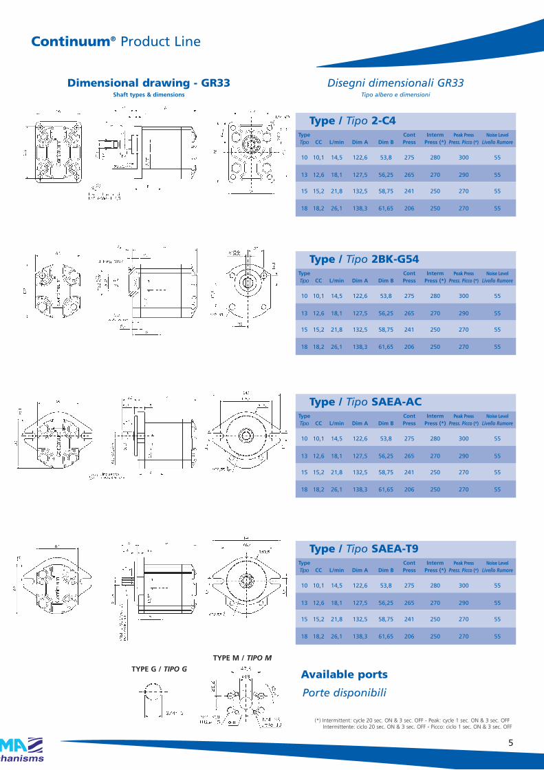
5
(*) Intermittent: cycle 20 sec. ON & 3 sec. OFF - Peak: cycle 1 sec. ON & 3 sec. OFFIntermittente: ciclo 20 sec. ON & 3 sec. OFF - Picco: ciclo 1 sec. ON & 3 sec. OFF
Dimensional drawing - GR33Shaft types & dimensions
Disegni dimensionali GR33Tipo albero e dimensioni
Type / Tipo 2-C4Type Cont Interm Peak Press Noise Level
Tipo CC L/min Dim A Dim B Press Press (*) Press. Picco (*) Livello Rumore
TYPE G / TIPO G
TYPE M / TIPO M
Available ports
Porte disponibili
10 10,1 14,5 122,6 53,8 275 280 300 55
13 12,6 18,1 127,5 56,25 265 270 290 55
15 15,2 21,8 132,5 58,75 241 250 270 55
18 18,2 26,1 138,3 61,65 206 250 270 55
Type / Tipo 2BK-G54Type Cont Interm Peak Press Noise Level
Tipo CC L/min Dim A Dim B Press Press (*) Press. Picco (*) Livello Rumore
10 10,1 14,5 122,6 53,8 275 280 300 55
13 12,6 18,1 127,5 56,25 265 270 290 55
15 15,2 21,8 132,5 58,75 241 250 270 55
18 18,2 26,1 138,3 61,65 206 250 270 55
Type / Tipo SAEA-ACType Cont Interm Peak Press Noise Level
Tipo CC L/min Dim A Dim B Press Press (*) Press. Picco (*) Livello Rumore
10 10,1 14,5 122,6 53,8 275 280 300 55
13 12,6 18,1 127,5 56,25 265 270 290 55
15 15,2 21,8 132,5 58,75 241 250 270 55
18 18,2 26,1 138,3 61,65 206 250 270 55
Type / Tipo SAEA-T9Type Cont Interm Peak Press Noise Level
Tipo CC L/min Dim A Dim B Press Press (*) Press. Picco (*) Livello Rumore
10 10,1 14,5 122,6 53,8 275 280 300 55
13 12,6 18,1 127,5 56,25 265 270 290 55
15 15,2 21,8 132,5 58,75 241 250 270 55
18 18,2 26,1 138,3 61,65 206 250 270 55
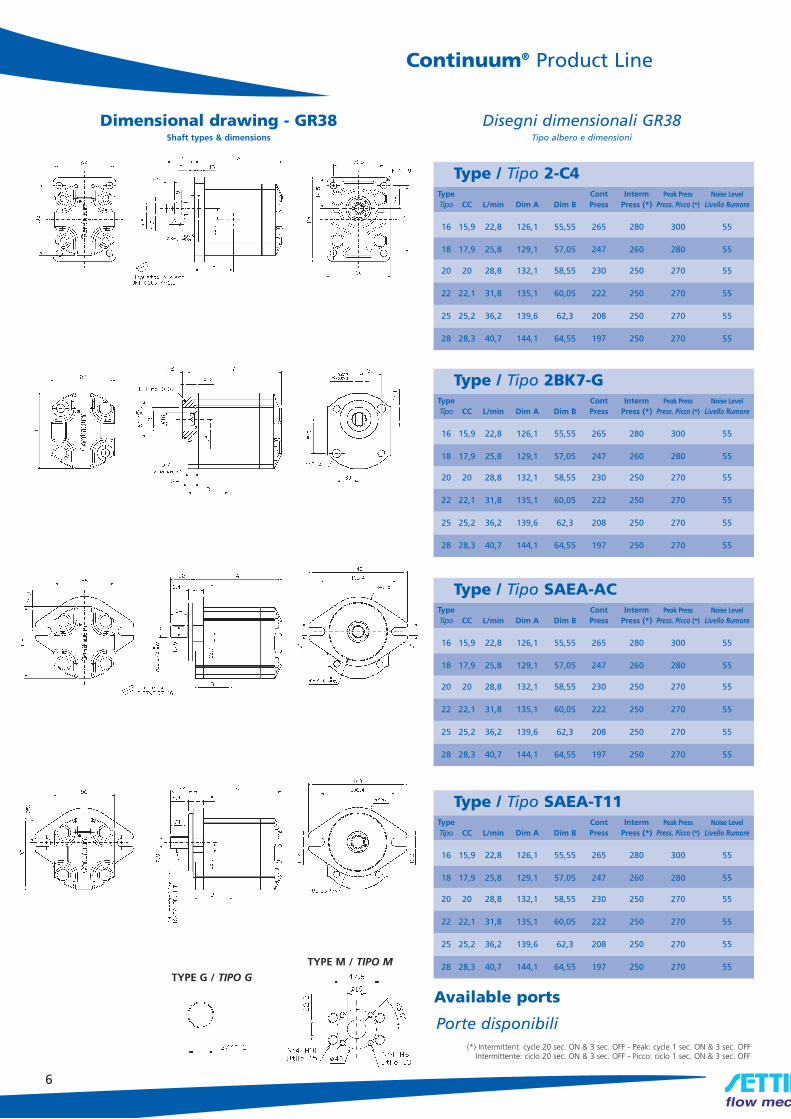
6
Continuum® Product Line
(*) Intermittent: cycle 20 sec. ON & 3 sec. OFF - Peak: cycle 1 sec. ON & 3 sec. OFFIntermittente: ciclo 20 sec. ON & 3 sec. OFF - Picco: ciclo 1 sec. ON & 3 sec. OFF
Dimensional drawing - GR38Shaft types & dimensions
Disegni dimensionali GR38Tipo albero e dimensioni
TYPE G / TIPO G
TYPE M / TIPO M
Available ports
Porte disponibili
16 15,9 22,8 126,1 55,55 265 280 300 55
18 17,9 25,8 129,1 57,05 247 260 280 55
20 20 28,8 132,1 58,55 230 250 270 55
22 22,1 31,8 135,1 60,05 222 250 270 55
25 25,2 36,2 139,6 62,3 208 250 270 55
28 28,3 40,7 144,1 64,55 197 250 270 55
Type / Tipo 2-C4Type Cont Interm Peak Press Noise Level
Tipo CC L/min Dim A Dim B Press Press (*) Press. Picco (*) Livello Rumore
16 15,9 22,8 126,1 55,55 265 280 300 55
18 17,9 25,8 129,1 57,05 247 260 280 55
20 20 28,8 132,1 58,55 230 250 270 55
22 22,1 31,8 135,1 60,05 222 250 270 55
25 25,2 36,2 139,6 62,3 208 250 270 55
28 28,3 40,7 144,1 64,55 197 250 270 55
Type / Tipo 2BK7-GType Cont Interm Peak Press Noise Level
Tipo CC L/min Dim A Dim B Press Press (*) Press. Picco (*) Livello Rumore
16 15,9 22,8 126,1 55,55 265 280 300 55
18 17,9 25,8 129,1 57,05 247 260 280 55
20 20 28,8 132,1 58,55 230 250 270 55
22 22,1 31,8 135,1 60,05 222 250 270 55
25 25,2 36,2 139,6 62,3 208 250 270 55
28 28,3 40,7 144,1 64,55 197 250 270 55
Type / Tipo SAEA-ACType Cont Interm Peak Press Noise Level
Tipo CC L/min Dim A Dim B Press Press (*) Press. Picco (*) Livello Rumore
16 15,9 22,8 126,1 55,55 265 280 300 55
18 17,9 25,8 129,1 57,05 247 260 280 55
20 20 28,8 132,1 58,55 230 250 270 55
22 22,1 31,8 135,1 60,05 222 250 270 55
25 25,2 36,2 139,6 62,3 208 250 270 55
28 28,3 40,7 144,1 64,55 197 250 270 55
Type / Tipo SAEA-T11Type Cont Interm Peak Press Noise Level
Tipo CC L/min Dim A Dim B Press Press (*) Press. Picco (*) Livello Rumore

Continuum® Product Line
15 25
16 28
18
PUMP PERFORMANCE CURVESFor Group 2 GROUP 2 Displacement CC/Rev
10 20
13 22
CURVE PRESTAZIONI POMPEper Gruppo 2
7
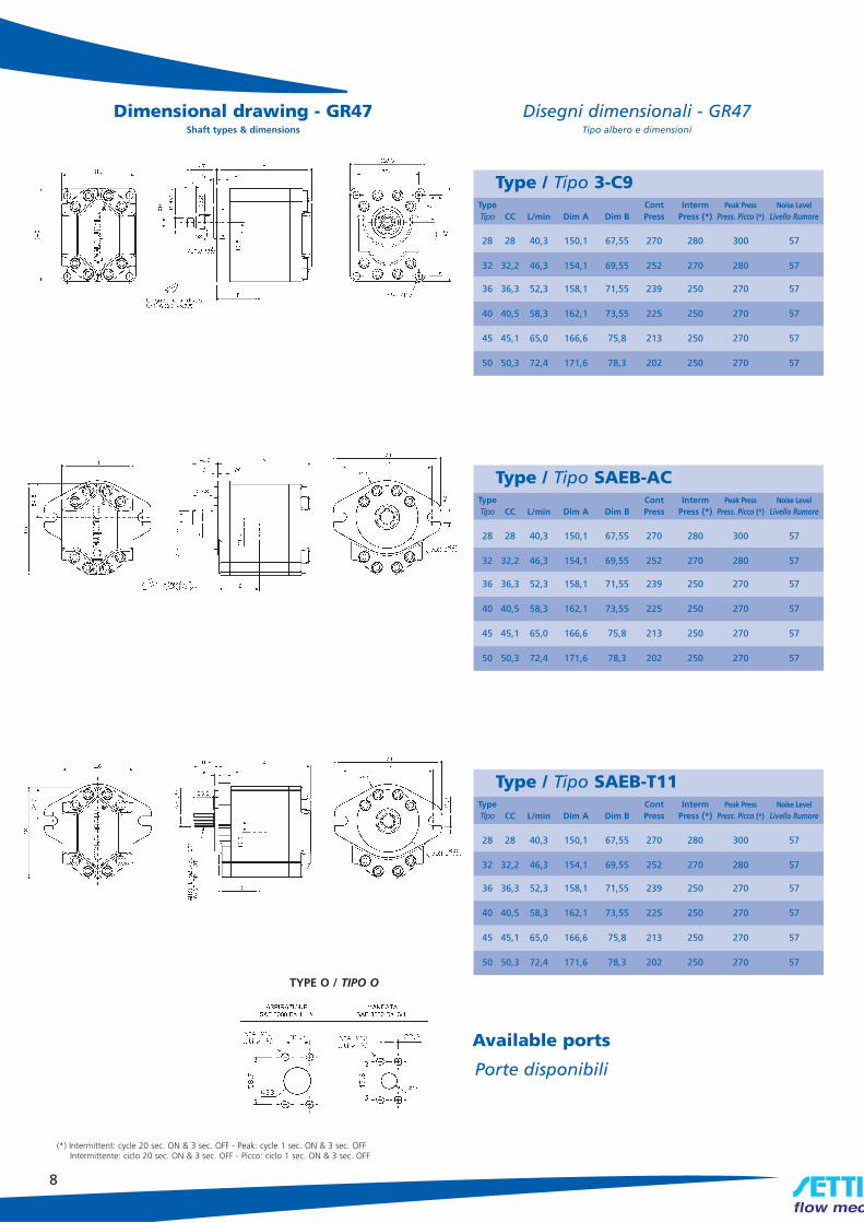
8
Dimensional drawing - GR47Shaft types & dimensions
Disegni dimensionali - GR47Tipo albero e dimensioni
(*) Intermittent: cycle 20 sec. ON & 3 sec. OFF - Peak: cycle 1 sec. ON & 3 sec. OFFIntermittente: ciclo 20 sec. ON & 3 sec. OFF - Picco: ciclo 1 sec. ON & 3 sec. OFF
TYPE O / TIPO O
Available ports
Porte disponibili
28 28 40,3 150,1 67,55 270 280 300 57
32 32,2 46,3 154,1 69,55 252 270 280 57
36 36,3 52,3 158,1 71,55 239 250 270 57
40 40,5 58,3 162,1 73,55 225 250 270 57
45 45,1 65,0 166,6 75,8 213 250 270 57
50 50,3 72,4 171,6 78,3 202 250 270 57
Type / Tipo 3-C9Type Cont Interm Peak Press Noise Level
Tipo CC L/min Dim A Dim B Press Press (*) Press. Picco (*) Livello Rumore
28 28 40,3 150,1 67,55 270 280 300 57
32 32,2 46,3 154,1 69,55 252 270 280 57
36 36,3 52,3 158,1 71,55 239 250 270 57
40 40,5 58,3 162,1 73,55 225 250 270 57
45 45,1 65,0 166,6 75,8 213 250 270 57
50 50,3 72,4 171,6 78,3 202 250 270 57
Type / Tipo SAEB-ACType Cont Interm Peak Press Noise Level
Tipo CC L/min Dim A Dim B Press Press (*) Press. Picco (*) Livello Rumore
28 28 40,3 150,1 67,55 270 280 300 57
32 32,2 46,3 154,1 69,55 252 270 280 57
36 36,3 52,3 158,1 71,55 239 250 270 57
40 40,5 58,3 162,1 73,55 225 250 270 57
45 45,1 65,0 166,6 75,8 213 250 270 57
50 50,3 72,4 171,6 78,3 202 250 270 57
Type / Tipo SAEB-T11Type Cont Interm Peak Press Noise Level
Tipo CC L/min Dim A Dim B Press Press (*) Press. Picco (*) Livello Rumore

Dimensional drawing - GR72Shaft types & dimensions
Disegni dimensionali - GR72Tipo albero e dimensioni
TYPE M / TIPO M
9
Dimensional drawing - GR55Shaft types & dimensions
Disegni dimensionali - GR55Tipo albero e dimensioni
(*) Intermittent: cycle 20 sec. ON & 3 sec. OFF - Peak: cycle 1 sec. ON & 3 sec. OFFIntermittente: ciclo 20 sec. ON & 3 sec. OFF - Picco: ciclo 1 sec. ON & 3 sec. OFF
Available ports
Porte disponibili
Available ports
Porte disponibili
TYPE O / TIPO O
94 94,1 136 245,2 125,6 270 280 300 57
101 101,45 147 248,2 127,1 252 270 300 57
125 125,5 181 258,2 132,1 239 250 300 57
150 150,9 218 268,7 137,35 225 250 275 57
175 175 253 278,7 142,35 213 250 275 57
200 200,4 290 289,2 147,6 202 250 275 57
Type / Tipo SAED-AACType Cont Interm Peak Press Noise Level
Tipo CC L/min Dim A Dim B Press Press (*) Press. Picco (*) Livello Rumore
94 94,1 136 245,2 125,6 270 280 300 57
101 101,45 147 248,2 127,1 252 270 300 57
125 125,5 181 258,2 132,1 239 250 300 57
150 150,9 218 268,7 137,35 225 250 275 57
175 175 253 278,7 142,35 213 250 275 57
200 200,4 290 289,2 147,6 202 250 275 57
Type / Tipo FSAED/A23TType Cont Interm Peak Press Noise Level
Tipo CC L/min Dim A Dim B Press Press (*) Press. Picco (*) Livello Rumore
Type / Tipo SAEB-ACType Cont Interm Peak Press Noise Level
Tipo CC L/min Dim A Dim B Press Press (*) Press. Picco (*) Livello Rumore
50 50,5 72,7 178,1 81,55 275 280 300 57
63 63,5 91,4 187,1 86,05 249 260 280 57
75 75 108,1 195,1 90,05 229 250 270 57
90 90,9 130,9 206,1 95,55 178 240 260 57
Type / Tipo SAEB-T15Type Cont Interm Peak Press Noise Level
Tipo CC L/min Dim A Dim B Press Press (*) Press. Picco (*) Livello Rumore
50 50,5 72,7 178,1 81,55 275 280 300 57
63 63,5 91,4 187,1 86,05 249 260 280 57
75 75 108,1 195,1 90,05 229 250 270 57
90 90,9 130,9 206,1 95,55 178 240 260 57

Dimensional drawing Tandem Group 1 + 1For unit dimensions please refer to GR28 dimensional drawings
Disegni dimensionali Tandem Gruppo 1+Gruppo 1Per dimensionali delle singole pompe vedere sezioni precedenti
4,2 90 275 280 300 55
6,4 95,5 275 280 300 55
8,3 100,5 246 260 280 55
10,2 105,5 222 250 270 55
12,9 112,4 176 230 250 55
4,2 95,6 275 280 300 55
6,4 101,1 275 280 300 55
8,3 106,1 230 240 270 55
10,2 111,1 190 210 240 55
12,9 118 150 170 200 55
GR28
GR28
10
Dimensional drawing Tandem Group 2 + 2For unit dimensions please refer to GR33 and GR38 dimensional drawings
Disegni dimensionali Tandem Gruppo 2+Gruppo 2Per dimensionali delle singole pompe vedere sezioni precedenti
010 113,6 275 280 300 55
013 118,5 265 270 300 55
015 123,5 241 250 300 55
018 129,3 206 250 300 55
016 120,1 265 280 300 55
018 123,1 247 260 300 55
020 126,1 230 250 300 55
022 129,1 222 250 300 55
025 133,6 208 250 300 55
028 138,1 197 250 300 55
GR33
GR38
Dimensional drawing Tandem Group 2 + 1For unit dimensions please refer to GR33 and GR38 dimensional drawings
Disegni dimensionali Tandem Gruppo 2+Gruppo 1Per dimensionali delle singole pompe vedere sezioni precedenti
010 115,6 275 280 300 55
013 120,5 265 270 300 55
015 125,5 241 250 300 55
018 131,3 206 250 300 55
016 122,1 265 280 300 55
018 125,1 247 260 300 55
020 128,1 230 250 300 55
022 131,1 222 250 300 55
025 135,6 208 250 300 55
028 140,1 197 250 300 55
GR33
GR38
For dimension “A” make reference to pages 4-9Per la misura “A” fare riferimento alle pagine da 4 a 9
Front Pump Cont Interm Peak Press Noise Level
1° stadio CC Dim D Press Press (*) Press. Picco (*) Livello Rumore
Front Pump Cont Interm Peak Press Noise Level
1° stadio CC Dim D Press Press (*) Press. Picco (*) Livello Rumore
Front Pump Cont Interm Peak Press Noise Level
1° stadio CC Dim D Press Press (*) Press. Picco (*) Livello Rumore
mm bar bar bar dB (A)
mm bar bar bar dB (A)
mm bar bar bar dB (A)

28 201,1 270 280 300 57
32 205,1 252 270 300 57
36 209,1 239 250 300 57
40 213,1 225 250 300 57
45 217,6 213 250 300 57
50 222,6 202 250 300 57
GR47
Disegni dimensionali Tandem Gruppo 3 + Gruppo 2Per dimensionali delle singole pompe vedere sezioni precedenti
Dimensional drawing Tandem Group 3 + 2For unit dimensions please refer to GR33 and GR38 dimensional drawings
Disegni dimensionali Tandem Gruppo 3 + Gruppo 3Per dimensionali delle singole pompe vedere sezioni precedenti
28 201,1 270 280 300 57
32 205,1 252 270 300 57
36 209,1 239 250 300 57
40 213,1 225 250 300 57
45 217,6 213 250 300 57
50 222,6 202 250 300 57
GR47
Dimensional drawing Tandem Group 3 + 3For unit dimensions please refer to GR33 and GR38 dimensional drawings
11
For dimension “A” make reference to pages 4-9Per la misura “A” fare riferimento alle pagine da 4 a 9
4
5
11 2 7
10
3
1
6 3
1 Flange/Flangia2 O-ring seal/O-ring3 Centring key /Spine di centraggio4 Body/Corpo
5 Bushings/Bronzine6 O-ring seal/O-ring7 Motor flange/Flangia motore8 Bushings/Bronzine
9 Continuum® rotor/Rotore Continuum®
10 Seal/Anello di tenuta11 Shaft key/Chiavetta12 Seeger / Seeger
83
9
3
12
Component description Descrizioni dei componenti
Front Pump Cont Interm Peak Press Noise Level
1° stadio CC Dim D Press Press (*) Press. Picco (*) Livello Rumore
mm bar bar bar dB (A)
mm bar bar bar dB (A)
Front Pump Cont Interm Peak Press Noise Level
1° stadio CC Dim D Press Press (*) Press. Picco (*) Livello Rumore

Main Office: Settima Flow Mechanisms s.r.l.29020 Loc. Conca di Settima - Gossolengo (PC) - ItalyTel: +39 0523 557623Fax: +39 0523 557256www.settimafm.com - [email protected]
Area Agency/Reseller
Ordering code / Codice d’ordinazione
Pump Type Class Displacement 1st stage Flange & Shaft Ports Displacement 2nd stage Ports Shaft Seal RotationTipo Classe Cilindrata primo stadio Flangia & Albero Porte Cilindrata secondo stadio Porte Guarnizione Rotazione
Albero
DG** 2V ***CC F****A*** * GR** ***CC * * **1 2 3 4 5 6 7 8 9 10
Pump Type Class Displacement Flange & Shaft Ports Shaft Seal RotationTipo Classe Cilindrata Flangia & Albero Porte Guarnizione Rotazione
Albero
GR** 2V ***CC F****A*** * * **1 2 3 4 5 6 7
Ordering code multiple pumps / Codice d’ordinazione pompe multiple
GR284,2 6,4 8,3 10,2 12,9
6 10 18 28 50 90 200
Dis
pla
cem
ent
(cc/
rev)
Cili
nd
rata
GR3310,1 12,6 15,2 18,2
GR3815,9 17,9 20,0 22,1 25,2 28,3
GR4728,0 32,2 36,3 40,5 45,1 50,3
GR5550,5 63,5 75,0 90,9
GR7294,1 101,4 125,5 150,9 175,0 200,4
1
2
3
4
Product Range / Gamma ProdottiGroup /Gruppo
33
28
38
47
55
010-013-015-018
016-018-020-022-025-028
028-032-036-040-045-050
050-063-075-090
F2AC4
004-006-008-010-013
F2AC4
F1AC3
First stage - primo stadio Second stage - secondo stadio
F2AC4
F3AC9
FSAEBAT15
G-M
G28
33
38
28
33
38
33
38
47
33
38
4755
G
G-M
G
G-M
G-M
O
G-M
O
004-006-008-010-013
010-013-015-018
016-018-020-022-025-028
004-006-008-010-013
010-013-015-018
016-018-020-022-025-028
010-013-015-018
016-018-020-022-025-028
028-032-036-040-045-050
28
33
38
47
55
72
G
G-M
O
M
004-006-008-010-013
010-013-015-018
016-018-020-022-025-028
028-032-036-040-045-050
050-063-075-090
094-101-125-150-175-200
F1AC3-F1PAC2-F1KAG54-F1LAGL54-FSAEAAC
F2AC4-F2BK7AG-FSAEAAC-FSAEAAT9
F2AC4-F2BK7AG-FSAEAAC-FSAEAAT11
F3AC9-FSAEBAC-FSAEBAT13
FSAEBAC-FSAEBAT15
FSAEDAC-FSAEDAT23
010-013-015-018
016-018-020-022-025-028
028-032-036-040-045-050050-063-075-090
O
O
(none)V
DX(default)
SX
(none)V
DX(default)
SX
Versione Cont_ITA-UK_1.2
ww
w.k
kic.
it
Recommended