Revision B
0XA6609-890000
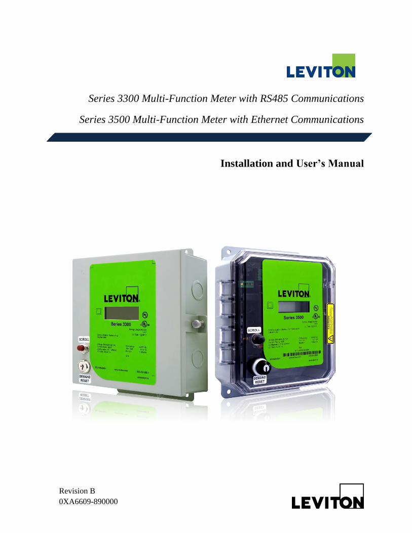
Series 3300 Multi-Function Meter with RS485 Communications
Series 3500 Multi-Function Meter with Ethernet Communications
Installation and User’s Manual
Revision 0.9 Series 3300/3500 Installation and User‘s Manual
Leviton Manufacturing Co., Inc. 1 Table of Contents
Table of Contents
1. Product Description .................................................................................................................... 3
1.1 General Description............................................................................................................... 3
1.2 Meter Features ....................................................................................................................... 3
2. Technical Specifications ............................................................................................................. 3
2.1 Part Number Keys ................................................................................................................. 3
2.2 Serial Number Description .................................................................................................... 4
2.3 Electrical Specifications ........................................................................................................ 5
2.4 I/O Connections and User Display ........................................................................................ 6
3. Installation Instructions ............................................................................................................... 8
3.1. Explanation of Warning Symbols ........................................................................................ 8
3.2 Safety Precautions ................................................................................................................. 9
3.3 Preparation ............................................................................................................................ 9
3.4 List of Materials .................................................................................................................. 10
3.5 Mounting the Enclosure ...................................................................................................... 10
3.5.1 Mounting Location ....................................................................................................... 10
3.5.2 Making Conduit Holes.................................................................................................. 10
3.5.3 Mounting Procedure and Conduit Installation.............................................................. 11
3.6 Installation of Voltage Lines ............................................................................................... 13
3.7 Variations and Installation of Current Transformers .......................................................... 14
3.8 Securing the Enclosure ........................................................................................................ 17
3.9 Turning Power On and Checking for Correct Functionality ............................................... 17
4. General Metering Features and Functionality ........................................................................... 18
4.1 Display ................................................................................................................................ 18
4.2 Display Sequence and Screen Numbers .............................................................................. 19
4.3 Power-on Sequence ............................................................................................................. 20
4.4 Descriptions of Displayed Information ............................................................................... 21
4.5 Manually Setting the Real Time Clock ............................................................................... 23
5. Real Time Clock (RTC) Battery Replacement ......................................................................... 24
6. Communications – Series 3300 RS485 Communication Models ............................................. 25
6.1 Modbus RTU Quick Start Guide ......................................................................................... 25

Revision 0.9 Series 3300/3500 Installation and User‘s Manual
Leviton Manufacturing Co., Inc. 2 Table of Contents
6.2 BACnet MS/TP Quick Start Guide ..................................................................................... 27
7. Communications – Series 3500 Ethernet Models ..................................................................... 29
8. Communications – History Data Extraction ............................................................................. 30
8.1 Connecting for History Data Extraction.............................................................................. 30
8.2 Data Extraction Procedure .................................................................................................. 31
9. Series 3300/3500 Pulse Outputs ............................................................................................ 35
9.1 Connecting to the Pulse Output Terminals ......................................................................... 35
9.2 Connecting Pulse Outputs to Data Acquisition Equipment. .............................................. 36
10. Diagnostic Tools and Frequently Asked Questions ................................................................ 37
10.1 Diagnostic Tools ............................................................................................................... 37
10.2 Frequently Asked Questions ............................................................................................ 37
11. Returned Material Policy and Warranty Information………………………………………..39
12. Contact Information ................................................................................................................ 40
Appendix A ................................................................................................................................... 41
Appendix B ................................................................................................................................... 45
Definitions
5-point rolling average: The valuations method used for most ‗instantaneous‘ readings,
including volts, amps, VA, and demand. It consists of the average of the 5 most recent sample
data, with samples occurring approximately every second.
Accuracy: The extent to which a given measurement agrees with the defined value.
Demand: The average power or related quantity over a specified period of time.
Demand-Maximum: The highest demand measured over a selected period of time.
Percentage Error: The difference between percentage registration and 100%.
Percentage Registration: The ratio of the actual registration to the true value, expressed as a
percent.
Power-Active: The time average of the instantaneous power over one period of a wave,
measured in Watts (W).
Power-Apparent: The product of rms current and voltage, measured in Volt-Amperes (VA).

Revision 0.9 Series 3300/3500 Installation and User‘s Manual
Leviton Manufacturing Co., Inc. 3
Registration: The amount of electric energy, or other quantity, recorded by the meter.
1. Product Description
1.1 General Description
Series 3300/3500 Meters are revenue grade kWh electrical meters featuring Time of Use
(TOU) meter readings, per-phase meter data, compatibility with either 3-phase Delta or Wye
configurations, and a user friendly LCD display.
1.2 Meter Features
Revenue-grade accuracy energy data with solid-core CTs or easy to install split-core
CTs
Wide operating temperature range
Built in LCD display
Battery backed-up real time clock (RTC) for TOU meter readings
Low voltage detection
CT reverse (energy direction) indicator arrow
Voltage, current, and power consumption per phase
Power Factor
Communication Options:
o RS485 Options (Series 3300)
Modbus RTU
BACnet MS/TP
o Ethernet Options (Series 3500)
Modbus TCP/IP
BACnet
o Isolated Pulse Outputs (10Wh and 1kWh), all models
10-year warranty
2. Technical Specifications
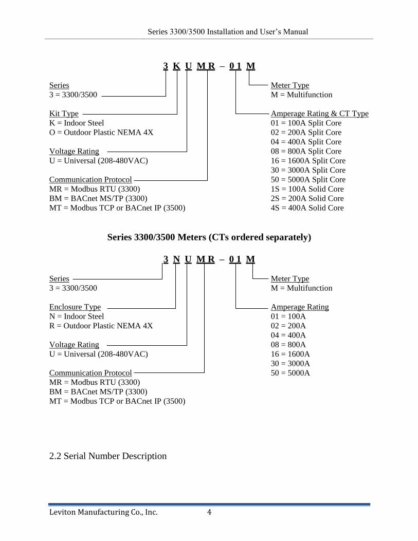
2.1 Part Number Keys
Series 3300/3500 Kits (CTs Included)
Revision 0.9 Series 3300/3500 Installation and User‘s Manual
Leviton Manufacturing Co., Inc. 4
3 K U M R – 0 1 M
Series Meter Type
3 = 3300/3500 M = Multifunction
Kit Type Amperage Rating & CT Type
K = Indoor Steel 01 = 100A Split Core
O = Outdoor Plastic NEMA 4X 02 = 200A Split Core
04 = 400A Split Core
Voltage Rating 08 = 800A Split Core
U = Universal (208-480VAC) 16 = 1600A Split Core
30 = 3000A Split Core
Communication Protocol 50 = 5000A Split Core
MR = Modbus RTU (3300) 1S = 100A Solid Core
BM = BACnet MS/TP (3300) 2S = 200A Solid Core
MT = Modbus TCP or BACnet IP (3500) 4S = 400A Solid Core
Series 3300/3500 Meters (CTs ordered separately)
3 N U M R – 0 1 M
Series Meter Type
3 = 3300/3500 M = Multifunction
Enclosure Type Amperage Rating
N = Indoor Steel 01 = 100A
R = Outdoor Plastic NEMA 4X 02 = 200A
04 = 400A
Voltage Rating 08 = 800A
U = Universal (208-480VAC) 16 = 1600A
30 = 3000A
Communication Protocol 50 = 5000A
MR = Modbus RTU (3300)
BM = BACnet MS/TP (3300)
MT = Modbus TCP or BACnet IP (3500)
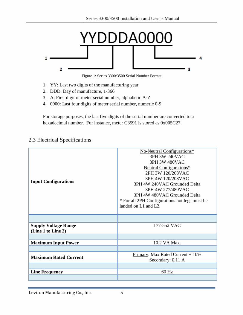
2.2 Serial Number Description
Revision 0.9 Series 3300/3500 Installation and User‘s Manual
Leviton Manufacturing Co., Inc. 5
Figure 1: Series 3300/3500 Serial Number Format
1. YY: Last two digits of the manufacturing year
2. DDD: Day of manufacture, 1-366
3. A: First digit of meter serial number, alphabetic A-Z
4. 0000: Last four digits of meter serial number, numeric 0-9
For storage purposes, the last five digits of the serial number are converted to a
hexadecimal number. For instance, meter C3591 is stored as 0x005C27.
2.3 Electrical Specifications
Input Configurations
No-Neutral Configurations*
3PH 3W 240VAC
3PH 3W 480VAC
Neutral Configurations*
2PH 3W 120/208VAC
3PH 4W 120/208VAC
3PH 4W 240VAC Grounded Delta
3PH 4W 277/480VAC
3PH 4W 480VAC Grounded Delta
* For all 2PH Configurations hot legs must be
landed on L1 and L2.
Supply Voltage Range
(Line 1 to Line 2)
177-552 VAC
Maximum Input Power 10.2 VA Max.
Maximum Rated Current Primary: Max Rated Current + 10%
Secondary: 0.11 A
Line Frequency 60 Hz
Revision 0.9 Series 3300/3500 Installation and User‘s Manual
Leviton Manufacturing Co., Inc. 6
Power Factor Range 0.5 to 1.0
leading or lagging
Accuracy1 kWh: Compliant with ANSI C12.1
Meter Operating Temperature -30 to +60 degrees C
Display Operating Temperature -20 to +50 degrees C
Terminal Blocks
Voltage Inputs 14 AWG, 12 in-lb of torque maximum
Current Transformers Inputs, Pulse and
RS485 outputs
14-18 AWG, 4.4 in-lb of torque maximum
Table 1: Series 3300/3500 electrical specifications
1Accuracy based on Leviton solid-core current transformers with 100 mA max output. Meter input burden
resistance at 1.62 Ohms. 2Pollution Degree 2: Normally only non-conductive pollution occurs. Occasionally, however, a temporary
conductivity caused by condensation must be expected.
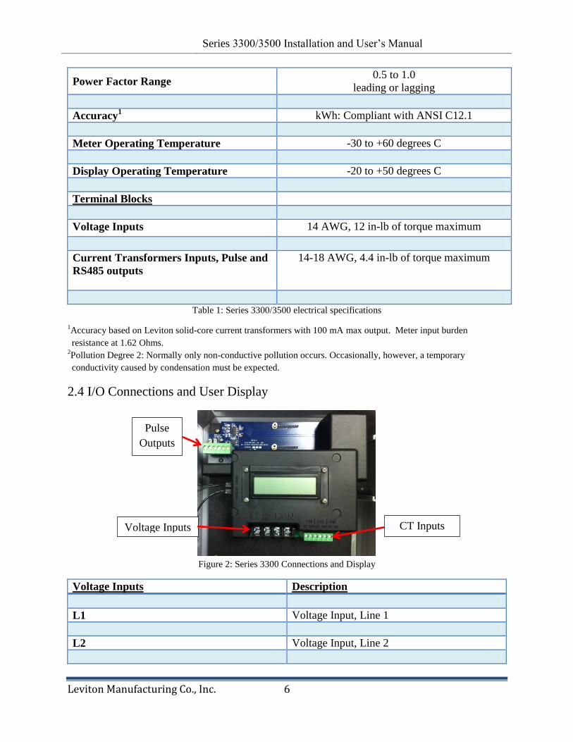
2.4 I/O Connections and User Display
Figure 2: Series 3300 Connections and Display
Voltage Inputs Description
L1 Voltage Input, Line 1
L2 Voltage Input, Line 2
Voltage Inputs CT Inputs
Pulse
Outputs
Revision 0.9 Series 3300/3500 Installation and User‘s Manual
Leviton Manufacturing Co., Inc. 7
L3 Voltage Input, Line 3 (if provided)
N Neutral input (if provided)
CT Inputs
CT1 : X1 Current Transformer input, CT1. Colored
wire of CT1
CT1 : X2 Current Transformer input, CT1. White wire
of CT1
CT2 : X1 Current Transformer input, CT2. Colored
wire of CT2
CT2 : X2 Current Transformer input, CT2. White wire
of CT2
CT3 : X1 Current Transformer input, CT3. Colored
wire of CT3
CT3 : X2 Current Transformer input, CT3. White wire
of CT3
Isolated Pulse Outputs
10 (+) Terminal 1 Real Energy (kWh) consumption (energy
delivered) pulse output, collector connection
of an NPN opto-isolated transistor. 10
Watthour (Wh) pulse rate (5 watthours on, 5
watthours off). VCE = 70VDC; ICE 50mA max
COM (-) Terminal 2 Common connection (emitters) for 10 Wh and
1 kWh Isolated Pulse Outputs.
1k (+) Terminal 3 Real Energy (kWh) consumption (energy
delivered) pulse output, plus (+) connection
(collector of an NPN opto-isolated transistor).
10 Watthour (Wh) pulse rate (500 watthours
on, 500 watthours off). VBCE = ?; ICE Max = ?
RS485 Connections For Modbus RTU and BACnet MS/TP. See
Revision 0.9 Series 3300/3500 Installation and User‘s Manual
Leviton Manufacturing Co., Inc. 8
Section 6 of this manual.
RJ-45 For Modbus TCP and BACnet IP. See
Section 7 of this manual.
Table 2: Series 3300 I/O connections
3. Installation Instructions
The following section contains installation and wiring instructions for Series 3300 and
Series 3500 meters in an outdoor or outdoor enclosure. If technical assistance is required
at any point during the installation, contact information can be found at the end of this
manual. Leviton is not responsible for damage to the meter caused by incorrect wiring.
3.1. Explanation of Warning Symbols
Indicates the need to consult the operation manual due to the
presence of a potential risk.
Indicates the presence of electric shock hazards. Prior to
proceeding, de-energize the circuit and consult the operation
manual.
Indicates that the equipment is protected throughout by
double insulation.
Table 3: Warning symbols

Revision 0.9 Series 3300/3500 Installation and User‘s Manual
Leviton Manufacturing Co., Inc. 9
3.2 Safety Precautions
WARNING
Installation of electric meters requires working with possibly hazardous voltages.
These instructions are meant to be a supplement to aid trained, qualified
professionals.
Turn off all power supplying the equipment before performing any wiring
operations. Use a properly rated voltage sensing device to confirm power is off.
Bonding is not automatic for metal conduit connections; separate bonding is to be
provided (see note 1).
Installations should be done in accordance with local codes and current National
Electric Code requirements.
Equipment used in a manner not specified by this document impairs the protection
provided by the equipment.
Failure to follow these warnings could result in serious injury or death.
1 Bonding kit must be UL recognized. Leviton recommends Rockwell Automation 855BM-ABK
3.3 Preparation
1. Verify the model number and electrical specifications of the device being installed to
confirm they are appropriate for the intended electrical service (see Section 2).
2. Consult local codes for any possible permits or inspections required before beginning
electrical work.
3. Outdoor applications: Ensure the conduit for the installation is flexible and non-
metallic. Conduit and conduit fittings must be rated UL Type 4X. Failure to use the
appropriate conduit impairs the degree of equipment protection.
4. Make sure all tools to be used during installation have proper insulation ratings.
5. Look inside the meter enclosure and electrical panel for possible exposed wire, broken
wire, damaged components or loose connections.
Revision 0.9 Series 3300/3500 Installation and User‘s Manual
Leviton Manufacturing Co., Inc. 10
3.4 List of Materials
Series 3300/3500 Meter and associated mounting materials.
Line 1, Line 2, Line 3 and Neutral hook-up wires as needed for the electrical service.
14 AWG wires recommended and 600VAC minimum rating required. Check local
electrical code for compliance with regulations.
List torque setting information.
Current Transformers (CTs): This product is designed for use with Leviton CTs; see
Section 3.7 for details.
Conduit and fittings (see note 5 in Section 3.3).
3.5 Mounting the Enclosure
3.5.1 Mounting Location
Series 3300/3500 meters require a switch or circuit breaker as part of the
building installation.
The switch or circuit breaker must be marked as the disconnecting device for
the meter.
It is recommended that the enclosure be mounted near the disconnecting
device in an area with adequate ventilation.
The enclosure should not be positioned in a manner that makes it difficult to
operate the disconnecting device.
Ensure that the lengths of the CT and voltage leads and conduit are capable of
reaching the enclosure from the breaker panel. See Section 10.2 for more
information.
If a suitable mounting location near the panel cannot be found, additional in-
line fuses or circuit breaker may be required in accordance with NEC
regulations.
3.5.2 Making Conduit Holes
Steel (Indoor) Enclosure
The Series 3300/3500 steel enclosure comes with several 1 1/16‖ knockouts
(3/4‖conduit). Remove as needed to connect conduit fittings. Reference voltage and CT
connections should enter in lower half of enclosure.
Outdoor Plastic Enclosure
The bottom, top, and non-hinge side of the plastic enclosure can be used as the conduit
location in outdoor single meter enclosures. Reference voltage and CT wires should enter

Revision 0.9 Series 3300/3500 Installation and User‘s Manual
Leviton Manufacturing Co., Inc. 11
in lower half of enclosure. If used, communication wires should enter in top-left of
enclosure. Conduit openings should be as far away from inner components as possible
for the installation. Opening sizes must be appropriate to fittings, and large enough to fit
all voltage and CT wiring. Keep drill bit away from components inside the enclosure.
Remove shavings from enclosure after drilling conduit holes.
3.5.3 Mounting Procedure and Conduit Installation
1. Fasten the enclosure to the selected surface using the mounting holes and appropriate
screws. There are mounting holes on both top and bottom of each enclosure. See
Figures 3 and 4 for mounting dimensions.
2. Upon mounting verify that the enclosure is not loose and that all connections are
secure.
3. Attach the conduit between enclosure and distribution panel, routing wires as
necessary for later use. For outdoor enclosures UL Type 4X conduit and fittings
must be used in order to maintain the outdoor rating of the enclosure.
4. Ensure conduit fittings are aligned properly and tightened securely to prevent
moisture from entering the enclosure (outdoor applications).

Revision 0.9 Series 3300/3500 Installation and User‘s Manual
Leviton Manufacturing Co., Inc. 12
Figure 3: Series 3300/3500 Indoor Steel Enclosure Dimensions, in Inches

Revision 0.9 Series 3300/3500 Installation and User‘s Manual
Leviton Manufacturing Co., Inc. 13
Figure 4: Series 3300/3500 Outdoor (plastic) Enclosure Dimensions, in Inches
3.6 Installation of Voltage Lines
Check to ensure service is disconnected before any connections are
made. Verify if additional in line fuses are required based on National
and Local electrical codes.
1. The Series 3300/3500 meter is compatible with both 3-phase 3-wire (no-neutral) and 3-
phase 4-wire systems. The meter derives power from the Line 1 and Line 2 voltage
connections, which must be between 177 and 552V for the meter to work properly. Field
wired voltage connections are made to the Series 3300/3500 voltage terminal block. The
rated torque for these terminal blocks is 12 in-lb., and can be used with 14 AWG solid or
stranded copper wires.
2. Connect 600 V min. insulated wiring for Line voltages and Neutral to the appropriate
locations in the breaker panel, in accordance with all national and local electrical codes;
see Hookup Diagrams in Figures 8 – 11 below for correct wiring information.
3. Route wires through the conduit if not already done.
4. Trim the wire to the appropriate length to avoid coils of excess wiring.
5. Connect additional in line fuses if required.
6. For connections to the Series 3300/3500 pulse outputs: Route wiring through the top of
the enclosure. Strip wiring to approximately .300 inches and connect to the appropriate
Revision 0.9 Series 3300/3500 Installation and User‘s Manual
Leviton Manufacturing Co., Inc. 14
terminals. Wires should be tightened so that they are held snuggly in place, but do not to
over-tighten, as this may compress and weaken the conductor.
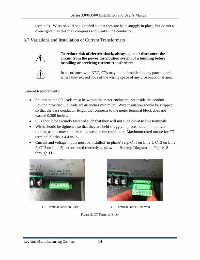
3.7 Variations and Installation of Current Transformers
To reduce risk of electric shock, always open or disconnect the
circuit from the power distribution system of a building before
installing or servicing current transformers.
In accordance with NEC, CTs may not be installed in any panel board
where they exceed 75% of the wiring space of any cross-sectional area.
General Requirements:
Splices on the CT leads must be within the meter enclosure, not inside the conduit.
Leviton provided CT leads are 48 inches minimum. Wire insulation should be stripped
so that the bare conductor length that connects to the meter terminal block does not
exceed 0.300 inches.
CTs should be securely fastened such that they will not slide down to live terminals.
Wires should be tightened so that they are held snuggly in place, but do not to over-
tighten, as this may compress and weaken the conductor. Maximum rated torque for CT
terminal blocks is 4.4 in-lb.
Current and voltage inputs must be installed ‗in phase‘ (e.g. CT1 on Line 1, CT2 on Line
2, CT3 on Line 3) and oriented correctly as shown in Hookup Diagrams in Figures 8
through 11.
CT Terminal Block in Place CT Terminal Block Removed
Figure 5: CT Terminal Block
Revision 0.9 Series 3300/3500 Installation and User‘s Manual
Leviton Manufacturing Co., Inc. 15
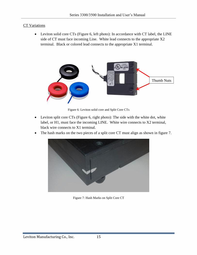
CT Variations
Leviton solid core CTs (Figure 6, left photo): In accordance with CT label, the LINE
side of CT must face incoming Line. White lead connects to the appropriate X2
terminal. Black or colored lead connects to the appropriate X1 terminal.
Figure 6: Leviton solid core and Split Core CTs
Leviton split core CTs (Figure 6, right photo): The side with the white dot, white
label, or H1, must face the incoming LINE. White wire connects to X2 terminal,
black wire connects to X1 terminal.
The hash marks on the two pieces of a split core CT must align as shown in figure 7.
Figure 7: Hash Marks on Split Core CT
Thumb Nuts
Revision 0.9 Series 3300/3500 Installation and User‘s Manual
Leviton Manufacturing Co., Inc. 16
CT Installation Procedures
1. Route CT secondary wires through conduit if not already done.
2. Trim the wire to the appropriate length to avoid coils of excess wiring.
3. Strip wiring to approximately .300 inches.
4. Connect the CT leads to the appropriate terminals; see Hookup Diagrams in
figures 8 through 11 below for correct CT orientations and connections. The
CT terminal block is removable to make wire connections easier; see Figure 5.
After securing CT wires to the appropriate terminals slide terminal block up
into header until fully seated.
6. For Split Core CTs: Remove two thumb nuts (Figure 6) and remove section
from CT. With power to the conductors turned off, place the 3-sided section
of the CT around the appropriate conductor while ensuring that white label,
white dot or H1 faces Line (source). Reassemble the CT while ensuring that
the white hash marks align (figure 5) and reinstall thumb nuts. Repeat for
remaining conductors for two or three phase applications, as shown in Figures
8 through 11.
7. For Solid Core CTs: With power turned off, disconnect each monitored
conductor one at a time and slide on appropriate CT, ensuring the CT is
correctly oriented as shown in Figures 8 through 11. Reconnect the
conductors.
Hookup Diagrams, Figures 8 through 11
Figure 8: 3-phase 4-wire Wye hookup diagram
LINE LOAD
IMPORTANT!
H1, white side, white dot,
or labeled side of CTs
must face source (LINE)
Series 3300/3500 Meter
3PH 4W Hookup
Revision 0.9 Series 3300/3500 Installation and User‘s Manual
Leviton Manufacturing Co., Inc. 17
Figure 9: 3-phase, 3-wire (no-Neutral) hookup diagram
3.8 Securing the Enclosure
The outdoor enclosure ships with a padlock and key for securing the door after
installation is complete. The indoor enclosure has a captive screw for securing the
enclosure door.
3.9 Turning Power On and Checking for Correct Functionality
1. After installation is completed and enclosure has been secured the meter may be
energized at the disconnect switch, upon which the meter will go through a power up
sequence as described in Section 4.3. It is strongly advised that users of this product
read Section 4 below for a complete description of meter functionality and displayed
values.
2. Several diagnostic tools built into the Series 3300/3500 meter that should be utilized to
ensure the meter and CTs are installed correctly and functioning properly:
a. Energy Flow arrow – Indicates direction of ‗energy flow‘ on amperage and kW
screens.
b. For mono-directional metering applications the Energy Flow arrow should always
point to the right. If an Amperage or kW screen shows the arrow pointing to the
left a current transformer may be installed backwards or on the wrong phase, or
CT connections at the meter may be reversed or connected to the wrong CT input
terminals, or voltage wires at the meter could be cross-phased. Section 4 further
describes how the Amperage screens operate to indicate a reverse energy
LINE LOAD
IMPORTANT!
H1, white side, white dot,
or labeled side of CTs
must face source (LINE)
Series 3300/3500 Meter
3PH 3W Hookup
Revision 0.9 Series 3300/3500 Installation and User‘s Manual
Leviton Manufacturing Co., Inc. 18
condition. Refer to Hookup Diagrams in Figures 8 through 11 for correct wiring
and CT orientations.
c. Power Factor Screens – Except in rare circumstances where predominantly
inductive loads are metered, Power Factor values should have an absolute value
greater than 0.6. A lower value indicates CTs installed on the wrong phase,
backwards, or incorrectly connected at the meter, or voltage connections at the
meter could be cross-phased. If PF is lower than 0.6 recheck CT placements and
orientations and CT and voltage connections at the meter against the appropriate
Hookup Diagram shown in Figures 8 through 11.
3. Bi-directional metering is typically used in grid-tied applications in which solar PV or
energy from a source other than the utility grid is fed into the metered service. CTs are
located between the grid and the electrical service so that if the locally generated energy
exceeds the service loads, the grid will receive energy instead of delivering it. The Series
3300/3500 meter indicates energy direction with the Energy Flow arrow and blinking
Amperage and phase indicator icons on the Amperage and kW screens.
4. General Metering Features and Functionality
4.1 Display
Figure 12: Custom LCD sections
Main Numerical Display and Scroll Button
The main numerical display section indicates the numerical value of the current item. After
startup sequence (see section 4.3) the display will revert to Real Energy (kWh) delivered
(consumed). The Scroll button on the enclosure door permits the user to scroll through nineteen
screens of information (00-18) as shown in Table 4. Depress and hold scroll button for a few
seconds to enter auto-scroll mode in which each screen appears for 4 seconds in the order shown
in Table 4. To return to manual mode press and release the scroll button briefly (less than one
second).
Phase Indicators and Parameter Indicators
Screen Number Main 7-Digit Numerical Display
Energy Flow Phase Indicators Parameter Indicators
PF

Revision 0.9 Series 3300/3500 Installation and User‘s Manual
Leviton Manufacturing Co., Inc. 19
The Phase and Parameter Indicator sections have two purposes. The Phase Indicators show the
phase currently being displayed on per-phase values. Parameter Indicators are associated with
values on the main numerical display.
Low Voltage
Low voltage (below minimum rated voltage with respect to neutral) on a phase is shown
by a blinking of the ‗V‘ Parameter Indicator in conjunction with corresponding Phase
Indicator. For example, if low voltage is detected on phase A the ‗V‘ Parameter Indicator
and the ‗A‘ phase indicator will blink simultaneously.
Energy Flow Indicator
On all Amps and kW screens the Energy Flow arrow will illuminate indicating energy
direction. Arrow pointing to the right indicates energy delivered (from grid for grid-tied
meters in renewable energy applications); arrow pointing to the left indicates energy
received (to the grid). In addition to the arrow, the Amps parameter indicator (―A‖) and
the corresponding phase indicator (A, B, or C) flash when Energy Flow arrow points left.
When meter is installed in a mono-directional metering application, the Amps and
kW arrows should always point to the right when load current is present.
4.2 Display Sequence and Screen Numbers
See Appendix B for examples of each display.

Revision 0.9 Series 3300/3500 Installation and User‘s Manual
Leviton Manufacturing Co., Inc. 20
Table 4: Screen Numbers and Sequence Order
4.3 Power-on Sequence
When the Series 3300/3500 meter is initially powered on it displays the following
sequence of information:
1. Hello screen.
2. Meter Serial Number
The Meter Serial Number screen displays first. The lower left number is the
alphabetical digit from the meter serial number (from 01=A to 26=Z), and the main
display shows the numerical portion of the Serial Number. For example, a display
showing ―03‖ on the left and ―6149‖ on the right below represents meter serial
number XXXXXC6149, with the X‘s indicating the manufacturing day and year. See
section 2.2 for more information on meter serial numbers.
3. Hardware Version -- The Hardware Version screen displays the word ‗Hard‘ and the
meter‘s hardware version.
Screen Numbers & Sequence Description
of Displayed Value
00 Real Time Clock
01 Real Energy Delivered (kWh)
02 Maximum Demand (MAX KW)
03 Max Demand Time (MAX)
04 Max Demand Date (MAX)
05 Voltage(V) Phase A
06 Voltage (V) Phase B
07 Voltage (V) Phase C
08 Voltage (V) Line A to B
09 Voltage (V) Line B to C
10 Voltage (V) Line A to C
11 Phase A Amps (A)
12 Phase B Amps (A)
13 Phase C Amps (A)
14 Real Power (kW) Phase A
15 Real Power (kW) Phase B
16 Real Power (kW) Phase C
17 Real Power (SUM kW) A+B+C
18 Power Factor (PF) Phase A
19 Power Factor (PF) Phase B
20 Power Factor (PF) Phase C
21 Frequency (HZ)

Revision 0.9 Series 3300/3500 Installation and User‘s Manual
Leviton Manufacturing Co., Inc. 21
4. Software Version -- The Software Version screen displays the word ―Soft‘ and the
meter‘s software version.
5. CT Ratio -- The CT Ratio screen displays the meter‘s programmed CT ratio. For
instance, ―400:0.1‖ indicates the meter has been calibrated for CTs with a 400:0.1A ratio.
6. Compute Engine Test Runs -- The compute engine performs 10 test runs before the meter
starts normal operation. The test runs are indicated by the TEST icon and the words
‗Pass X‘, where X is the test run number.
Once the startup sequence has completed the display defaults to Screen 01, Real Energy (kWh)
delivered (consumed).
4.4 Descriptions of Displayed Information
Push and release the scroll button to cycle through the display screens. Each button press
moves to the next screen in the sequence shown in table 4. After 5 minutes of inactivity
on the scroll button the display will return to Screen 01, Real Energy Delivered (kWh)
and remain there until the scroll button is depressed again.
Refer to section 4.1 for a description of how to set the meter into auto-scroll mode. In
this mode the display is updated every four seconds to cycle through the screens
automatically.
All displayed values update approximately once a second.
Screen 00 – Real Time Clock. Real Time Clock (RTC) is factory set to Pacific
Time (GMT-8). A factory-installed battery backup maintains the RTC before the
meter is installed and in power loss situations.
For information on replacing the battery, please see section 5. The RTC can be set
using the communications port as described in sections 6 and 7 or by using the
procedure outlined in Section 4.5.
Screen 01 – kWh – Real Energy Delivered (consumed), non-resettable. After
initial startup the display reverts to and stays on this screen unless scroll or auto-scroll
functions are initiated. The displayed value correlates to ―kWh from grid‖ stored in
Modbus or BACnet Address 0004 (see Sections 6 and 7). In the event of a power loss
Real Energy Delivered data will be saved in EEPROM and retained even if backup
battery is depleted. The direction arrow always points to the right to indicate energy
consumed (delivered).
Screen 02 – kW Max – Maximum Demand – can be calculated in 15 or 30 minute
blocks. The default value from factory is 15 minutes. The interval can be changed
using the RS485 communication port (see sections 6 and 7).

Revision 0.9 Series 3300/3500 Installation and User‘s Manual
Leviton Manufacturing Co., Inc. 22
o Sub-intervals – Each Max Demand data block has 3 sub-intervals in which
demand is calculated. Sub-intervals are 5 minutes for a 15 minute Max
Demand block and 10 minutes for a 30 minute block. For each sub-interval
the total kWh consumption is divided by the number of accumulations to give
average demand for the sub-interval. Accumulations occur approximately
every second.
o Max Demand calculation – After each sub-interval is finished, a new block
demand is calculated. The block demand is comprised of the average of the 3
most recent sub-intervals. The largest block demand since a demand reset is
stored as the maximum demand. When an update of the maximum demand
occurs, the new value and current date and time are saved to EEPROM,
Modbus Address 0060. Max Demand is displayed in kW.
o Max Demand Reset. All series 3300/3500 meters have the capability to reset
maximum demand. When maximum demand is reset, the maximum block
demand and all current sub-interval demands are set to zero. An internal
register is also incremented upon demand reset to keep a total of the times this
action was taken. The register is a single byte, and rolls over at 255. The
register content is accessible and Max Demand can be reset via the
communications port; see sections 6 and 7. Max Demand also can be reset
with the keyed switch on the meter enclosure door. Turn the key lock into the
‗on‘ position for at least 5 seconds. When Max Demand is reset manual or via
the coms port the LCD will give a visual confirmation that the demand was
reset.
Screens 03 and 04 – Max Demand time and date – displayed immediately following
the Max Demand screen.
Screens 05-13 – Voltage (V) and Amperage (A)
o Volts and Amps are saved and displayed as root mean square (RMS) values.
Appropriate Phase Indicators and Display Indictors will illuminate as shown
in Figure 12. On all Amps and kW screens the Energy Flow arrow will
illuminate indicating energy direction. Arrow pointing to the right indicates
energy delivered (from grid); arrow pointing to the left indicates energy
received (to the grid, for grid-tied meters in renewable energy applications).
In addition to the arrow, the Amps indicator (―A‖) and the corresponding
phase indicator (A, B, or C) flash when Energy Flow arrow points left. If
meter is installed in a mono-directional application, the Amps and kW arrows
should always point to the right when load current is present.
Screens 14-17 – Real Power Delivered (consumed) kW A, kW B, kW C, kW
SUM - Also known as Instantaneous Demand – is a 5-point rolling average of
individual and all phases (kW SUM). Displayed values correspond to ―Phase A Real
Revision 0.9 Series 3300/3500 Installation and User‘s Manual
Leviton Manufacturing Co., Inc. 23
Power,‖ ―Phase B Real Power,‖ ―Phase C Real Power,‖ and ―Total Power (A+B+C)‖
in Modbus Register Map (see Appendix A).
Screens 18-20 – Power Factor (PF) – Per-phase Power Factor is displayed. A
lagging power factor is indicated by the Energy Flow arrow pointing to the left; for
leading power factor arrow points to the right.
Screen 21 – Frequency (HZ) – Displayed in Hertz.
4.5 Manually Setting the Real Time Clock
Figure 13: SCROLL and Max Demand/Clock Reset Switch on Outdoor Series 3300/3500 Meter
1. Press and hold the SCROLL pushbutton; see Figure 13.
2. While holding SCROLL, rotate the Max Demand Reset/RTC KEYSWITCH to the right
into the RESET/ON position within 3 seconds and then release it. Date will be displayed
and Year will flash.
3. Press SCROLL to advance the Year (you may also hold it down to advance
automatically). The Year will cycle from 12 through 99 then back to 12 (for 2012
through 2099).
4. When the Year is set, rotate the KEYSWITCH to ON again and release. The Month will
now flash.
5. Set the Month (1 to 12).
6. Repeat for Day of the Month (range varies by month and leap-year).
7. The next KEYSWITCH ON/release cycle will show the Time and flash the Hour.
8. Repeat the setting sequence for Hour (0-23), Minutes (0-59) and Seconds (0-59).
9. You may again perform KEYSWITCH ON/Release to cycle back to the Date settings, if
desired.
10. The Date/Time setting mode will end automatically after no user activity for 10
seconds. The Date/Time settings will be stored and the meter will return to its normal
display operation.
SCROLL
Pushbutton
Max Demand
Reset/RTC
KEYSWITCH shown
in OFF/Normal
position
Outdoor Models Indoor Models
Revision 0.9 Series 3300/3500 Installation and User‘s Manual
Leviton Manufacturing Co., Inc. 24
Note:
The Day of the Week (Sunday through Saturday) is calculated and stored
automatically by the meter.
Metering functions and communications are not affected during this Date/Time
setting process.
5. Real Time Clock (RTC) Battery Replacement
If the battery depletes and no power is connected to the meter the RTC resets to 01/01/00 00:00:00
when power returns. The battery backup is a standard CR2025 lithium coin cell, rated at 3V and
165 mAh. The lifetime of the battery depends on the operating temperature of the meter, as shown
in Table 5.
Operating
Temperature (◦C)
Estimated Battery Life
(No external power) (Years)
Estimated Battery Life
(90% power uptime) (Years)
Temp < 25 3 19
25 < Temp < 60 2 12
Temp > 60 1 9 Table 5: Battery Life Estimates
Since minimal current is drawn from the battery when the meter in powered on, most batteries do
not need replaced over the lifetime of the meter. If a situation occurs in which the meter will be
powered off for a prolonged period, battery life will be significantly reduced. In the event that the
battery needs replaced while the meter is still in operation, follow the instructions below.
To reduce risk of electric shock, always open or disconnect the
circuit from the power distribution system of a building before
servicing an electric meter. Use a properly rated voltage sensing
device to confirm power is off.
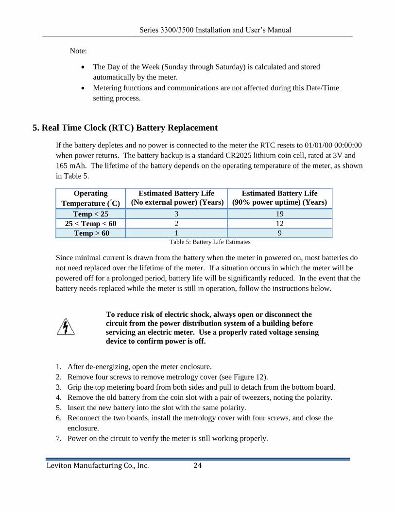
1. After de-energizing, open the meter enclosure.
2. Remove four screws to remove metrology cover (see Figure 12).
3. Grip the top metering board from both sides and pull to detach from the bottom board.
4. Remove the old battery from the coin slot with a pair of tweezers, noting the polarity.
5. Insert the new battery into the slot with the same polarity.
6. Reconnect the two boards, install the metrology cover with four screws, and close the
enclosure.
7. Power on the circuit to verify the meter is still working properly.
Revision 0.9 Series 3300/3500 Installation and User‘s Manual
Leviton Manufacturing Co., Inc. 25
8. Resynchronize the RTC using the communications port as described in Sections 6 and 7 or set
manually using procedure described in Section 4.5.
Figure 12: Metrology Cover Screws
6. Communications – Series 3300 RS485 Communication Models
6.1 Modbus RTU Quick Start Guide
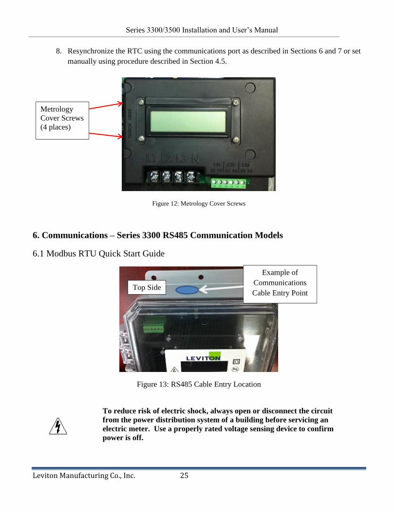
Figure 13: RS485 Cable Entry Location
To reduce risk of electric shock, always open or disconnect the circuit
from the power distribution system of a building before servicing an
electric meter. Use a properly rated voltage sensing device to confirm
power is off.
Top Side
Example of
Communications
Cable Entry Point
Metrology
Cover Screws
(4 places)

Revision 0.9 Series 3300/3500 Installation and User‘s Manual
Leviton Manufacturing Co., Inc. 26
1. Install meter as outlined in Section 3.
2. Modbus cable shall enter at the TOP side of the enclosure as shown in Figure 13. Use shielded
twisted-pair cable to prevent interference. Replace plastic cap 33with webbed bushing (provided).
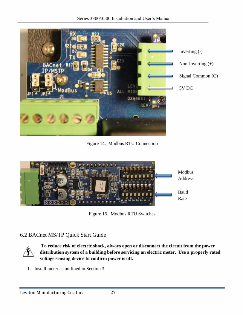
3. Connect Inverting (-), Non-Inverting (+), and Signal Common (C) wires using the 4-pin removable
terminal block shown in Figure 14. Do not over-tighten the terminal screws. Modbus output is
electrically isolated from input power.
4. Select Modbus address using the upper bank of DIP switches labeled ―ADDRESS‖ as shown in
Figure 15. Switch 1 corresponds to the low-order bit of the address and setting a switch ON
selects a bit value of 1. For example, set switches 1 and 3 on to select address 5.
5. Select Modbus baud rate using the switches 1 and 2 in the lower bank of DIP switches, labeled
―BAUD‖ as shown in Figure 15. Switches 3 – 8 are reserved for future use and must be set to the
OFF position. Baud rate options are shown in Table 6.
6. Before energizing the meter close and secure the enclosure door.
Switch Baud Rate
1 2
Off Off 9600
On Off 19200
Off On 38400
On On 76800
Table 6. Modbus RTU Baud Rate Switch Settings
Revision 0.9 Series 3300/3500 Installation and User‘s Manual
Leviton Manufacturing Co., Inc. 27
Figure 14. Modbus RTU Connection
Figure 15. Modbus RTU Switches
6.2 BACnet MS/TP Quick Start Guide
To reduce risk of electric shock, always open or disconnect the circuit from the power
distribution system of a building before servicing an electric meter. Use a properly rated
voltage sensing device to confirm power is off.
1. Install meter as outlined in Section 3.
Inverting (-)
Non-Inverting (+)
Signal Common (C)
5V DC
Modbus
Address
Baud
Rate
Revision 0.9 Series 3300/3500 Installation and User‘s Manual
Leviton Manufacturing Co., Inc. 28
2. BACnet cable shall enter at the TOP side of the enclosure as shown in Figure 13. Use shielded
twisted-pair cable to prevent interference. Replace plastic cap with webbed bushing (provided).
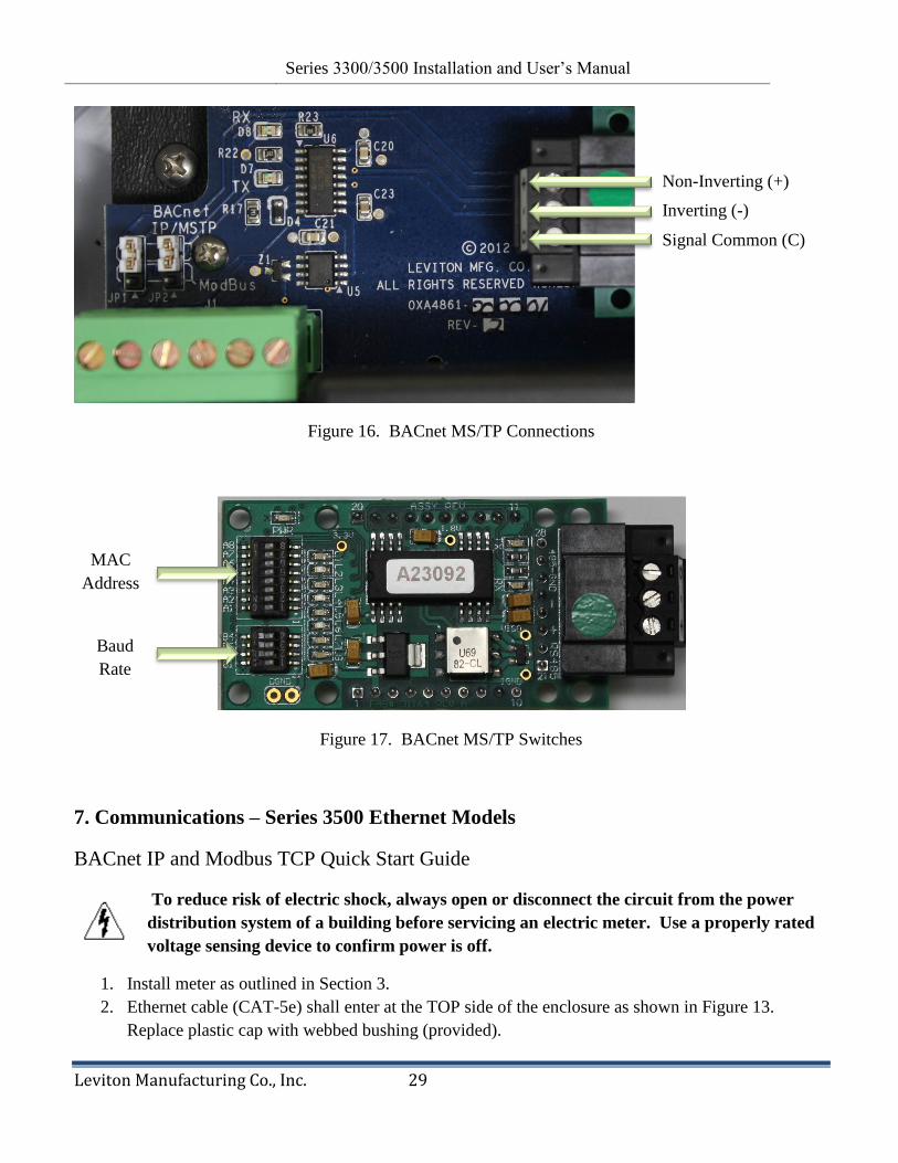
3. Connect Inverting (-), Non-Inverting (+), and Signal Common (C) wires using the 3-pin removable
terminal block shown in Figure 16. Do not over-tighten the terminal screws. BACnet output is
electrically isolated from input power.
4. Select the 8-bit MS/TP MAC address using DIP switches A1 – A8 (Figure 17. Switch A1
corresponds to the low-order bit of the address and setting a switch ON selects a bit value of 1.
For example, set switches 1 and 2 on to select MAC address 3 (binary value 00000011).
5. Select the baud rate using DIP switches B1 – B4 as shown in Figure 17. Baud rate options are
shown in Table 7.
6. Before energizing the meter close and secure the enclosure door.
Note: For detail information refer to FieldServer Website: www.fieldserver.com
Switch Baud Rate
B1 B2 B3 B4
Off Off Off Off Auto
On Off Off Off 110
Off On Off Off 300
On On Off Off 600
Off Off On Off 1200
On Off On Off 2400
Off On On Off 4800
On On On Off 9600
Off Off Off On 19200
On Off Off On 20833
Off On Off On 28800
On On Off On 38400
Off Off On On 57600
On Off On On 76800
Off On On On 115200
Table 7. BACnet MS/TP Baud Rate Switch Settings
Revision 0.9 Series 3300/3500 Installation and User‘s Manual
Leviton Manufacturing Co., Inc. 29
Figure 16. BACnet MS/TP Connections
Figure 17. BACnet MS/TP Switches
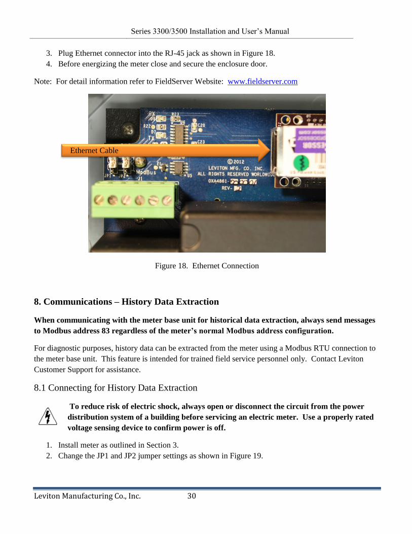
7. Communications – Series 3500 Ethernet Models
BACnet IP and Modbus TCP Quick Start Guide
To reduce risk of electric shock, always open or disconnect the circuit from the power
distribution system of a building before servicing an electric meter. Use a properly rated
voltage sensing device to confirm power is off.
1. Install meter as outlined in Section 3.
2. Ethernet cable (CAT-5e) shall enter at the TOP side of the enclosure as shown in Figure 13.
Replace plastic cap with webbed bushing (provided).
Non-Inverting (+)
Inverting (-)
Signal Common (C)
MAC
Address
Baud
Rate
Revision 0.9 Series 3300/3500 Installation and User‘s Manual
Leviton Manufacturing Co., Inc. 30
3. Plug Ethernet connector into the RJ-45 jack as shown in Figure 18.
4. Before energizing the meter close and secure the enclosure door.
Note: For detail information refer to FieldServer Website: www.fieldserver.com
Figure 18. Ethernet Connection
8. Communications – History Data Extraction
When communicating with the meter base unit for historical data extraction, always send messages
to Modbus address 83 regardless of the meter’s normal Modbus address configuration.
For diagnostic purposes, history data can be extracted from the meter using a Modbus RTU connection to
the meter base unit. This feature is intended for trained field service personnel only. Contact Leviton
Customer Support for assistance.
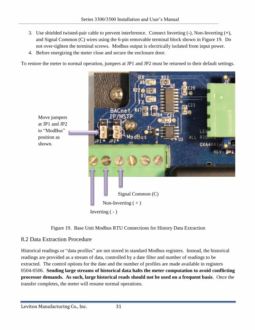
8.1 Connecting for History Data Extraction
To reduce risk of electric shock, always open or disconnect the circuit from the power
distribution system of a building before servicing an electric meter. Use a properly rated
voltage sensing device to confirm power is off.
1. Install meter as outlined in Section 3.
2. Change the JP1 and JP2 jumper settings as shown in Figure 19.
Ethernet Cable
Revision 0.9 Series 3300/3500 Installation and User‘s Manual
Leviton Manufacturing Co., Inc. 31
3. Use shielded twisted-pair cable to prevent interference. Connect Inverting (-), Non-Inverting (+),
and Signal Common (C) wires using the 6-pin removable terminal block shown in Figure 19. Do
not over-tighten the terminal screws. Modbus output is electrically isolated from input power.
4. Before energizing the meter close and secure the enclosure door.
To restore the meter to normal operation, jumpers at JP1 and JP2 must be returned to their default settings.
Figure 19. Base Unit Modbus RTU Connections for History Data Extraction
8.2 Data Extraction Procedure
Historical readings or ―data profiles‖ are not stored in standard Modbus registers. Instead, the historical
readings are provided as a stream of data, controlled by a date filter and number of readings to be
extracted. The control options for the date and the number of profiles are made available in registers
0504-0506. Sending large streams of historical data halts the meter computation to avoid conflicting
processor demands. As such, large historical reads should not be used on a frequent basis. Once the
transfer completes, the meter will resume normal operations.
Inverting ( - )
Non-Inverting ( + )
Signal Common (C)
Move jumpers
at JP1 and JP2
to ―ModBus‖
position as
shown.

Revision 0.9 Series 3300/3500 Installation and User‘s Manual
Leviton Manufacturing Co., Inc. 32
Setting the Date
The historical data access date provides filtering criteria for data retrieval. By default, all historical data
access dates are ―don‘t care‖ (0xFF). When a date value is ―don‘t care‖, it has no effect on the filtering of
historical data. Any other value acts as a filter for the data retrieved from memory. The date value
specifies the oldest data to be retrieved. For instance, setting the historical data year to 0x08 will filter out
any meter readings prior to 2008. Each part of the historical date is treated as an independent filter. Some
examples are provided below in Table 8 to further illustrate.
Year Month Date Hour Meter Readings Sent
0xFF 0xFF 0xFF 0xFF Any
0x08 0xFF 0xFF 0xFF Any reading in 2008 or later
0xFF 0x06 0xFF 0xFF Any reading from June-Dec in any year
0x09 0x06 0xFF 0xFF Any reading in June, 2009 or later
0xFF 0xFF 0xFF 0x11 Any reading after 5:00 PM on any day of any year
0x09 0x03 0x01 0xFF Any reading on March 01, 2009 or later
0xFF 0xFF 0x1C 0x17 Any reading after 11:00 PM on the 28th
to the end of the
month
Table 8. Setting the Historical Data Access Date
The historical data access date information is stored in registers 0504 and 0505 (0x01F8 and 0x01F9).
The year and month are stored in register 0504, and the date and hour are stored in register 0505.
Initiating Data Retrieval and Controlling the Number of Profiles Sent
To initiate historical data retrieval, a read holding register command is issued to address 0506. The
―number of registers‖ variable in the read command controls the number of historical profiles to be
extracted. Once the desired number of readings has been found and transferred the transmission ends.
Historical Data Profile Structure
The historical data is transmitted in frames consisting of 48 bytes each. The frame structure is shown in
Table 9.
Data profile information, except RTC, kWh and VAh, is saved in 16-bit floating point format using
truncation of the least significant decimal information. To increase resolution from truncating data for
storage, each part of the profile has an associated multiplier. When data is extracted, first make the 16-bit
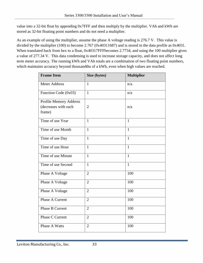
Revision 0.9 Series 3300/3500 Installation and User‘s Manual
Leviton Manufacturing Co., Inc. 33
value into a 32-bit float by appending 0x7FFF and then multiply by the multiplier. VAh and kWh are
stored as 32-bit floating point numbers and do not need a multiplier.
As an example of using the multiplier, assume the phase A voltage reading is 276.7 V. This value is
divided by the multiplier (100) to become 2.767 (0x40311687) and is stored in the data profile as 0x4031.
When translated back from hex to a float, 0x40317FFFbecomes 2.7734, and using the 100 multiplier gives
a value of 277.34 V. This data condensing is used to increase storage capacity, and does not affect long
term meter accuracy. The running kWh and VAh totals are a combination of two floating point numbers,
which maintains accuracy beyond thousandths of a kWh, even when high values are reached.
Frame Item Size (bytes) Multiplier
Meter Address 1 n/a
Function Code (0x03) 1 n/a
Profile Memory Address
(decreases with each
frame)
2 n/a
Time of use Year 1 1
Time of use Month 1 1
Time of use Day 1 1
Time of use Hour 1 1
Time of use Minute 1 1
Time of use Second 1 1
Phase A Voltage 2 100
Phase A Voltage 2 100
Phase A Voltage 2 100
Phase A Current 2 100
Phase B Current 2 100
Phase C Current 2 100
Phase A Watts 2 100
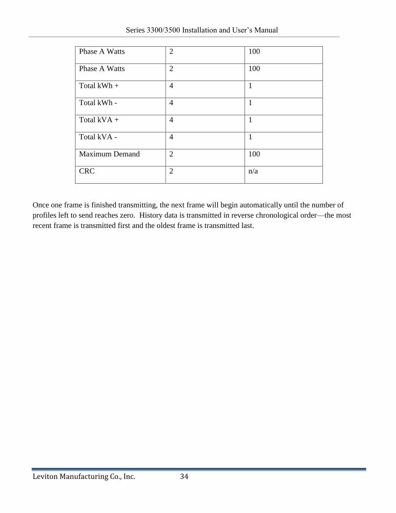
Revision 0.9 Series 3300/3500 Installation and User‘s Manual
Leviton Manufacturing Co., Inc. 34
Phase A Watts 2 100
Phase A Watts 2 100
Total kWh + 4 1
Total kWh - 4 1
Total kVA + 4 1
Total kVA - 4 1
Maximum Demand 2 100
CRC 2 n/a
Once one frame is finished transmitting, the next frame will begin automatically until the number of
profiles left to send reaches zero. History data is transmitted in reverse chronological order—the most
recent frame is transmitted first and the oldest frame is transmitted last.

Revision 0.9 Series 3300/3500 Installation and User‘s Manual
Leviton Manufacturing Co., Inc. 35
9. Series 3300/3500 Pulse Outputs
9.1 Connecting to the Pulse Output Terminals
To reduce risk of electric shock, always open or disconnect the circuit
from the power distribution system of a building before servicing an
electric meter. Use a properly rated voltage sensing device to confirm
power is off.
1. Install meter as outlined in Section 3.
2. Communications cable shall enter at the TOP side of the enclosure as shown in Figure 13.
Replace plastic cap with webbed bushing (provided).
3. Use shielded twisted-pair cable to prevent interference and connect to the 6-pin removable
terminal block as shown in Figure 18. Two pins provide 10 watt-hour and 1 kWh pulse
rates. Pulses at these terminals and positive (+) with respect to the shared common
(―COM‖) terminal (-), and represent energy delivered (from grid). Do not over-tighten the
terminal screws. Both pulse outputs are electrically isolated from input power and can be
used independent of one another or simultaneously.
4. Before energizing the meter close and secure the enclosure door.
Revision 0.9 Series 3300/3500 Installation and User‘s Manual
Leviton Manufacturing Co., Inc. 36
Figure 18. Pulse Output Connections
9.2 Connecting Pulse Outputs to Data Acquisition Equipment.
A variety of data acquisition equipment may be connected to the Series 3300/3500 pulse output terminals,
included wireless pulse transceivers and data logging equipment. For information on Leviton‘s complete
line of data acquisition products go to Leviton.com >Products>Submetering>Communication Systems.
For information on Leviton‘s software solutions go to Leviton.com>Products>Submetering>Energy
Manager Software.
10 Wh/P COM 1 kWh/P

Revision 0.9 Series 3300/3500 Installation and User‘s Manual
Leviton Manufacturing Co., Inc. 37
10. Diagnostic Tools and Frequently Asked Questions
10.1 Diagnostic Tools
Several diagnostic tools built into the Series 3300/3500 meter should be utilized to ensure the
meter and CTs are installed correctly and functioning properly.
1) Energy Flow arrow (see Section 4.1, Figure 12) – Indicates direction of ‗energy flow‘ on
amperage and kW screens.
a. For mono-directional metering applications the Energy Flow arrow should
always point to the right. If an Amperage or kW screen shows the arrow
pointing to the left a current transformer may be installed backwards or on the
wrong phase, or CT connections at the meter may be reversed or on the wrong
phase. See Hookup Diagrams in Figures 8 through 11 for correct wiring and CT
orientations.
b. Blinking ―A‖ on the Amperage screens – Indicates reverse energy flow. The
c. Bi-directional metering is typically used in grid-tied applications where solar PV
or energy from a source other than the utility grid may be interconnected to the
metered service. CTs are located between the grid and the electrical service, and
if the locally generated energy exceeds the service loads the grid will receive
energy instead of delivering it. In such circumstances the Energy Flow arrow will
point to left when energy is being received (at the grid) and point to the right
when energy is being delivered from the grid.
2) Power Factor Screens – Except in rare circumstances where predominantly inductive
loads are metered, Power Factor values should be between -0.5 and +0.5. An absolute
value less than 0.5 indicates CTs installed on the wrong phase or backwards. Recheck
wiring and CT orientations against the appropriate Hookup Diagram shown in Figures 8
through 11.
10.2 Frequently Asked Questions
Q: Can I use a single phase (split phase 3-wire) Series 3300/3500 meter on a three phase
feed?
A: The Series 3300/3500 can monitor two phases of a three phase system (2 Phase 3 or 4 Wire)
but cannot monitor Single Phase (Split Phase) 120/240V 3-Wire, nor 120V 2-Wire circuits. The
line-to-line voltage display will not show 240V for the Split Phase.
Q: Can I route voltage input wires and current sensing leads through the same conduit?
A: Yes. CTs must have 18 AWG or heavier wires with proper VAC insulation rating (check
local electrical code).

Revision 0.9 Series 3300/3500 Installation and User‘s Manual
Leviton Manufacturing Co., Inc. 38
Q: Can I extend the CT leads?
A: Yes. You should try to avoid extending the native CT leads by locating the meter next to the
circuit breaker. If you must extend the leads, take into consideration the following inaccuracy
contributors. Here are some of the factors that will affect accuracy when using long CT leads:
1. Wire Length
o Native CT length is best
o Longer run decreases accuracy
2. CT wire gauge (18 AWG preferred)
o Thinner wire > more resistance > affects accuracy
o Thicker wire > more capacitance > affects accuracy
3. Conduit material
o Metal conduit will effect accuracy
o Non-metal conduit has minimal effect
4. High voltage wires run in parallel with CT wires inside the same conduit
o Approximately 0.7%/100ft. deviation at 277V
o Approximately 0.5%/100ft. deviation at 120V
o Accuracy deviation increases as current increases on the voltage wires.
5. Wire type
o When extending CT leads, twisted pair wire type gives better accuracy.
Q: How do I retrieve Data from the meter?
A: Data Acquisition equipment, also known as Automatic Meter Reading (AMR) and
Middleware (between the consists of radio transmitters, repeaters, and a collector that monitors,
records, and transmits data to energy management or billing software solutions. Various
software solutions manage and display data in user-friendly formats. See Sections 6 and 7 or go
to Leviton.com for more information.
Q: Why are solid core current transformers color coded (Black & white, red & white, and
blue & white)?
A: Industry convention for color coding in 3 Phase 208V electrical systems assigns the color
black to phase A, red to phase B, Blue to phase C, and white to Neutral. Leviton‘s 100A and
200A solid core CTs are coded with the same colors (on the body of the CTs and on the wires) to
help installers get each CT placed on the correct hot leg. Further, the white half of the CT
always faces incoming Line or source. Phase A CT (black) connects to CT1 at the meter, phase
B CT (Red) connects to CT2, and phase C CT (blue) connects to CT3. See hookup diagrams in
figures 8 through 11.
Q: Can digital output wires be routed through the same conduit as voltage input and
current sensing wires?
A: No. In accordance with NEC and UL requirements, Class 2 wiring (digital inputs/outputs)
must be separated from Class 1 wiring. Digital output wires must enter the meter housing
through the top of the enclosure, and voltage and CT wires must enter at bottom of enclosure.
See Installation Instructions in Section 3.
Q: I still can’t get my meter to work, what now?
A: Contact technical support at via phone or email; see Contact Information on following page.
Revision 0.9 Series 3300/3500 Installation and User‘s Manual
Leviton Manufacturing Co., Inc. 39
11. Returned Material Policy and Warranty Information
After acceptance, all sales of meters are final. Leviton, in its sole discretion, authorizes
product returns in appropriate circumstances, subject to such conditions as Leviton may
specify. Any such return is subject to the express prior authorization and approval of
Leviton. Buyer must notify Leviton at 800-736-6682 (telephone) or 503-404-5594 (fax)
and request a Returned Material Authorization Number (RMA Number) and state the
specific reason for return. Unauthorized returns will not be accepted.
When requesting an RMA Number please supply the following information:
1. Distributors name and address
2. Model number of meter
3. Original purchase order number
4. Reason for return
All paperwork and boxes must be marked with an RMA number issued by Leviton. All
authorized returned materials must be shipped freight prepaid to Leviton to the address
specified below. Leviton is not responsible for uninsured packages or packages lost by
your carrier.
Leviton 20497 SW Teton Avenue Tualatin, Oregon 97062
All returns are subject to a handling/restocking charge, except for product shipped in error or
products under warranty. All charges (modification, repair, restock etc) related to returned
products will be determined by Leviton upon evaluation. All shipping costs are the responsibility
of the buyer.
METERS RETURNED FOR CREDIT*
Replacement meter ordered RMA Number requested by stocking distributor for credit must be
accompanied by a purchase order for material of equal or greater value.
NO replacement meter ordered
METERS RETURNED FOR REPAIR (STILL UNDER WARRANTY)*
No defects found $75.00 evaluation charge
Defects not covered under warranty Charges upon evaluation
Defects found covered under warranty No Charge
METERS RETURNED FOR EVALUATION (NO LONGER UNDER WARRANTY)*
Evaluation charge of $75.00 applies
0% Restock Charge
25% Restock Charge

Revision 0.9 Series 3300/3500 Installation and User‘s Manual
Leviton Manufacturing Co., Inc. 40
Other charges will apply depending on evaluation by Leviton
12. Contact Information
Leviton Manufacturing Co., Inc. Global Headquarters 201 N. Service Rd. Melville, NY 11747-3138 • Tech Line: 1-800-824-3005 • FAX: 1-800-832-9538 Leviton Manufacturing Co., Inc. Lighting & Energy Solutions 20497 SW Teton Avenue, Tualatin, OR 97062 • Telephone: 1-800-736-6682 • FAX: 503-404-5594 Tech Line: (6:00AM-4:00PM P.S.T. Monday-Friday): 1-800-959-6004 Leviton Manufacturing of Canada, Ltd. 165 Hymus Boulevard, Pointe Claire, Quebec H9R 1E9 • Telephone: 1-800-469-7890 • FAX: 1-800-563-1853 Leviton S. de R.L. de C.V. Lago Tana 43, Mexico DF, Mexico CP 11290 • Tel. (+52) 55-5082-1040 • www.leviton.com.mx Visit our Website at www.leviton.com/les © 2012 Leviton Manufacturing Co., Inc. All rights reserved. Subject to change without notice.
*Prices as of May 01, 2009 and subject to change
Revision 0.9 Series 3300/3500 Installation and User‘s Manual
Leviton Manufacturing Co., Inc. 41
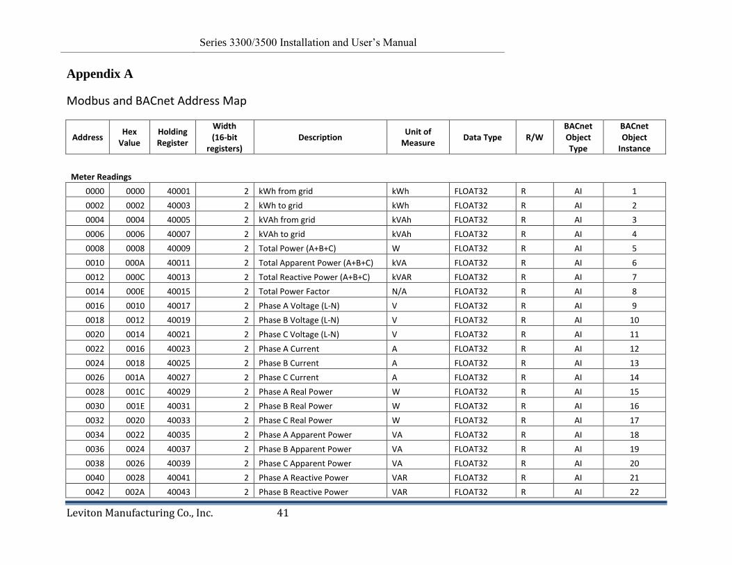
Appendix A
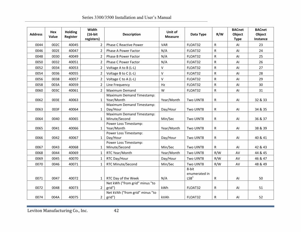
Modbus and BACnet Address Map
Address Hex
Value Holding Register
Width (16-bit
registers) Description
Unit of Measure
Data Type R/W BACnet Object Type
BACnet Object
Instance
Meter Readings 0000 0000 40001 2 kWh from grid kWh FLOAT32 R AI 1
0002 0002 40003 2 kWh to grid kWh FLOAT32 R AI 2 0004 0004 40005 2 kVAh from grid kVAh FLOAT32 R AI 3 0006 0006 40007 2 kVAh to grid kVAh FLOAT32 R AI 4 0008 0008 40009 2 Total Power (A+B+C) W FLOAT32 R AI 5 0010 000A 40011 2 Total Apparent Power (A+B+C) kVA FLOAT32 R AI 6 0012 000C 40013 2 Total Reactive Power (A+B+C) kVAR FLOAT32 R AI 7 0014 000E 40015 2 Total Power Factor N/A FLOAT32 R AI 8 0016 0010 40017 2 Phase A Voltage (L-N) V FLOAT32 R AI 9 0018 0012 40019 2 Phase B Voltage (L-N) V FLOAT32 R AI 10 0020 0014 40021 2 Phase C Voltage (L-N) V FLOAT32 R AI 11 0022 0016 40023 2 Phase A Current A FLOAT32 R AI 12 0024 0018 40025 2 Phase B Current A FLOAT32 R AI 13 0026 001A 40027 2 Phase C Current A FLOAT32 R AI 14 0028 001C 40029 2 Phase A Real Power W FLOAT32 R AI 15 0030 001E 40031 2 Phase B Real Power W FLOAT32 R AI 16 0032 0020 40033 2 Phase C Real Power W FLOAT32 R AI 17 0034 0022 40035 2 Phase A Apparent Power VA FLOAT32 R AI 18 0036 0024 40037 2 Phase B Apparent Power VA FLOAT32 R AI 19 0038 0026 40039 2 Phase C Apparent Power VA FLOAT32 R AI 20 0040 0028 40041 2 Phase A Reactive Power VAR FLOAT32 R AI 21 0042 002A 40043 2 Phase B Reactive Power VAR FLOAT32 R AI 22
Revision 0.9 Series 3300/3500 Installation and User‘s Manual
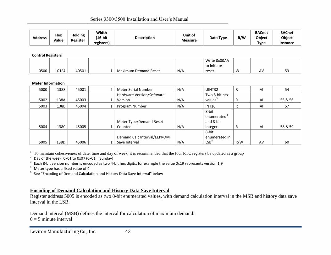
Leviton Manufacturing Co., Inc. 42
Address Hex
Value Holding Register
Width (16-bit
registers) Description
Unit of Measure
Data Type R/W BACnet Object Type
BACnet Object
Instance
0044 002C 40045 2 Phase C Reactive Power VAR FLOAT32 R AI 23 0046 002E 40047 2 Phase A Power Factor N/A FLOAT32 R AI 24 0048 0030 40049 2 Phase B Power Factor N/A FLOAT32 R AI 25 0050 0032 40051 2 Phase C Power Factor N/A FLOAT32 R AI 26 0052 0034 40053 2 Voltage A to B (L-L) V FLOAT32 R AI 27 0054 0036 40055 2 Voltage B to C (L-L) V FLOAT32 R AI 28 0056 0038 40057 2 Voltage C to A (L-L) V FLOAT32 R AI 29 0058 003A 40059 2 Line Frequency Hz FLOAT32 R AI 30 0060 003C 40061 2 Maximum Demand W FLOAT32 R AI 31
0062 003E 40063 1 Maximum Demand Timestamp: Year/Month Year/Month Two UINT8 R AI 32 & 33
0063 003F 40064 1 Maximum Demand Timestamp: Day/Hour Day/Hour Two UINT8 R AI 34 & 35
0064 0040 40065 1 Maximum Demand Timestamp: Minute/Second Min/Sec Two UINT8 R AI 36 & 37
0065 0041 40066 1 Power Loss Timestamp: Year/Month Year/Month Two UINT8 R AI 38 & 39
0066 0042 40067 1 Power Loss Timestamp: Day/Hour Day/Hour Two UINT8 R AI 40 & 41
0067 0043 40068 1 Power Loss Timestamp: Minute/Second Min/Sec Two UINT8 R AI 42 & 43
0068 0044 40069 1 RTC Year/Month Year/Month Two UINT8 R/W AV 44 & 45 0069 0045 40070 1 RTC Day/Hour Day/Hour Two UINT8 R/W AV 46 & 47 0070 0046 40071 1 RTC Minute/Second Min/Sec Two UINT8 R/W AV 48 & 49
0071 0047 40072 1 RTC Day of the Week N/A
8-bit enumerated in LSB
1 R AI 50
0072 0048 40073 2 Net kWh ("from grid" minus "to grid") kWh FLOAT32 R AI 51
0074 004A 40075 2 Net kVAh ("from grid" minus "to grid") kVAh FLOAT32 R AI 52
Revision 0.9 Series 3300/3500 Installation and User‘s Manual
Leviton Manufacturing Co., Inc. 43
Address Hex
Value Holding Register
Width (16-bit
registers) Description
Unit of Measure
Data Type R/W BACnet Object Type
BACnet Object
Instance
Control Registers
0500 01F4 40501 1 Maximum Demand Reset N/A
Write 0x00AA to initiate reset W AV 53
Meter Information 5000 1388 45001 2 Meter Serial Number N/A UINT32 R AI 54
5002 138A 45003 1 Hardware Version/Software Version N/A
Two 8-bit hex values
3 R AI 55 & 56
5003 138B 45004 1 Program Number N/A INT16 R AI 57
5004 138C 45005 1 Meter Type/Demand Reset Counter N/A
8-bit enumerated
4
and 8-bit integer R AI 58 & 59
5005 138D 45006 1 Demand Calc Interval/EEPROM Save Interval N/A
8-bit enumerated in LSB
5 R/W AV 60
1 To maintain cohesiveness of date, time and day of week, it is recommended that the four RTC registers be updated as a group
2 Day of the week: 0x01 to 0x07 (0x01 = Sunday)
3 Each 8-bit version number is encoded as two 4-bit hex digits, for example the value 0x19 represents version 1.9
4 Meter type has a fixed value of 4
5 See “Encoding of Demand Calculation and History Data Save Interval” below
Encoding of Demand Calculation and History Data Save Interval
Register address 5005 is encoded as two 8-bit enumerated values, with demand calculation interval in the MSB and history data save
interval in the LSB.
Demand interval (MSB) defines the interval for calculation of maximum demand:
0 = 5 minute interval
Revision 0.9 Series 3300/3500 Installation and User‘s Manual
Leviton Manufacturing Co., Inc. 44
1 = 10 min interval
Other values return an error
History interval (LSB) defines the interval for saving history data in EEPROM:
1 = 5 minute interval
3 = 15 minute interval
6 = 30 minute interval
12 = 60 minute interval
Other values return an error
When this register is read, the demand calculation interval appears in the MSB and history data save interval is in the LSB.
The method of writing to the register depends on the communication protocol. For Modbus RTU, the demand calculation interval
value is written to the LSB and the history data save interval is fixed at 5 minutes and cannot be changed. For all other protocols, the
demand calculation interval value is written to the MSB and the history data save interval value is written to the LSB.
Revision 0.9 Series 3300/3500 Installation and User‘s Manual
Leviton Manufacturing Co., Inc. 45
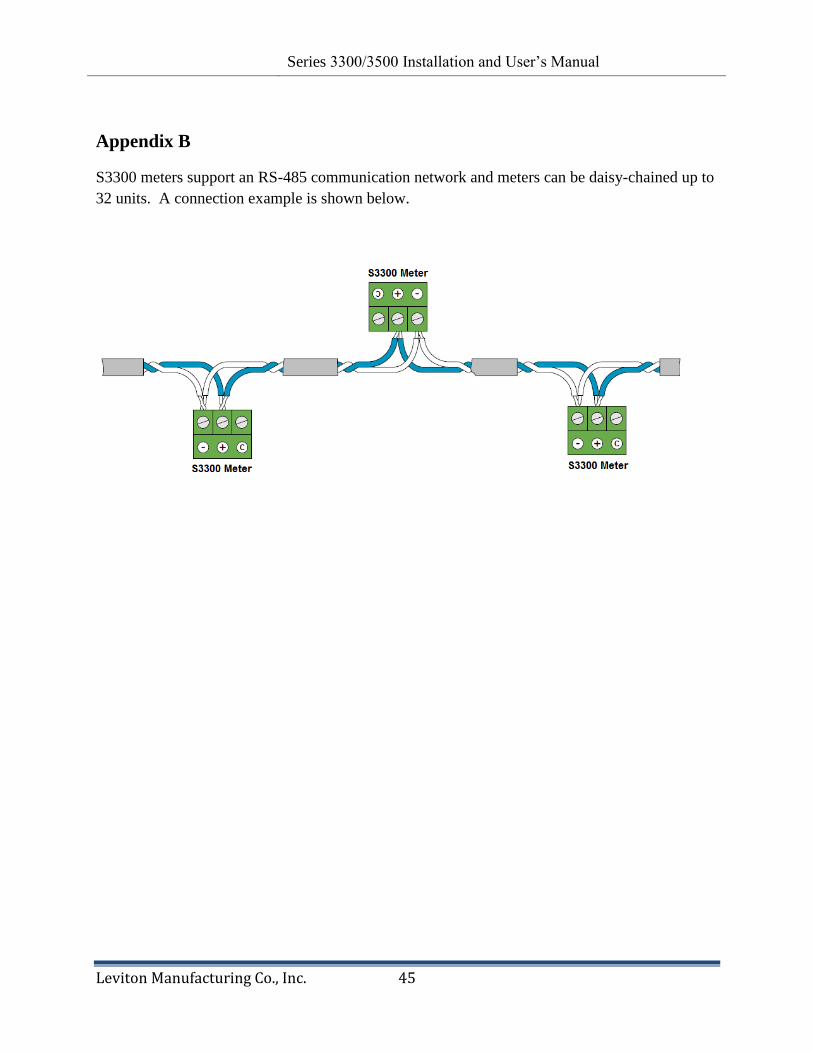
Appendix B
S3300 meters support an RS-485 communication network and meters can be daisy-chained up to
32 units. A connection example is shown below.
Recommended