Rohrbündelwärmetauscher
Serie - SKM/EKM

� Ölseite:optimierte Leistung durchFin-Technik
� Wasserseite:optimierte Standzeit durchWasserrohre
� Kleine Wasserrohre� Tankaufbaukühler� Wärmeabfuhr bis 1000 kW� Durchflussmengen
bis 1200 l/min� Cu-/CuNi-/SS-Rohre
� Oil-side:optimized performancedue to fin-technic
� Waterside:optimized standing timedue to water tubes
� Small water tubes� On tank mounted cooler� Heat dissipation up to
1000 kW� Flow rates up to 1200 l/min� Cu-/CuNi-/SS-tubes
� Côté de l'huile:Performance optimiséepar Fin-Technologie
� Côté de l'eau:Durée de vie optimiséepar tuyeaux d'eau
� Petites tuyeaux d'eau� Refroidisseur monté
sur tank� Dissipation de chaleur
jusqu’à 1000 kW� Débit jusqu’à 1200 l/mn.� Cu-/CuNi-/SS-tuyaux
Öl/Wasser-WärmetauscherOil/water heat exchangersEchangeur thermique huile/eau
Serie
EKM/SKMFür den industriellen Einsatz
For industrial use
A usage industriel
Die Schnittperspektive zeigt Mantel mitStahlwänden und Hoch leis tungs-Kühlungs -kam mer mit Kupfernickel rohr und Alumini-umrippen.
The cut-away perspective shows the shellwith steel walls and high-performance coo-ling chamber incorporating copper tubesand aluminium cooling fins.
La perspective de coupe montre un man-teau aux parois d’acier, et une chambre àrefroidissement haute performance avectuyau de cuivre et nervures aluminium.
1
www.hainzl.at

Produktbeschreibung / Product description / Discription du produit
Standard Option Seewasser / Sea water / eau de merStandard
Mantel / Shell / Manteau,
Befestigung / Mounting / Fixation,
Umlenksegmente / Baffels / Chicanes: Stahl / Steel / Acier SS
Rohrboden / Tube sheet / Base des tuyeaux: Stahl / Steel / Acier SS Messing/Naval brass/Laiton
Kühlrippen / Cooling fins / Fins de refroidissment, Aluminium Cu
Typenschild / Label / Plaque signalétique:
Rohre / Tubes / Tuyeaux: Cu Cu/Ni SS Cu/Ni
Endkappen / End caps / Caches: Grauguß / Cast iron / SS Grauguß* / Cast iron* / Fonte grise*
Fonte grise oder/or/ou Rotguß / Gun metal
Zusätzlich einbauen / Additional installation / Zink-Anode** / zinc anode** / Anode de zink**
installer additional
* Mit einem speziellen chem. Nickel-Beschichtungsverfahren / Nickel coating treatment / Traité avec un procédure de nickel
** Nur bei Rotguß Deckel / only with gun metal end cap
Produktbeschreibung
Die EKM/SKM-Serie ist eine konsequenteWei ter entwicklung eines Rohrbündel-Wärme tauschers für weite An wendungs -gebiete in der Industrie. Durch die zusätzli-che Kühlfläche ist diese Baureihe äußersteffektiv, mit einer Wärme leistung bis zu1000 kW. Dies wird durch Alu minium -lamellen, die über das Rohrbündel gescho-ben werden und me tal lisch verbun den sind,realisiert. Die EKM/SKM-Wärme tauscherhaben eine Kühl fläche von 0,43 m2 bis 56 m2. Die Serie EKM/SKM setzt sich aus 43 Grund einheiten zu sammen.
Produktmerkmale
� Aluminiumrippen sorgen fürvergrößerten Wärmeaustausch
� Wärmeabfuhr bis 1000 kW� Öl-Durchflußmengen bis zu 1200 l/min� Abnehmbare Endkappen für einfache
Reinigung der Rohre� Flansche ermöglichen Drehung des
Wärmetauschers um 90°� Wahlweise mit internem Umgehungs-
rückschlagventil (Patentiert)� Max. Druck: Öl 35 bar / Wasser 16 bar
Option� Seewasserfähige Ausführung� Zertifikate im Bereich Marine� Druckluftanwendung� Wasser-Wasser Anwendung� Edelstahlausführung oder
chemische Vernickelung
Product description
The EKM/SKM series is a logical furtherdevelopment of a tube-bank heat exchangerfor a wide range of industrial applications.This range is particularly effective due tothe additional cooling area, and offers aheat exchange performance of 1000 kW.This is produced by aluminium fins, whichare pushed over the bank of tubes withmetal-to-metal contact. The EKM range ofheat exchangers has a cooling surface offrom 0.43 m2 to 56 m2.The EKM/SKM series is constructed of 43 basic units.
Product features
� Aluminium fins ensure larger levels ofheat exchange
� Heat dissipation up to 1000 kW� Oil flow rates of up to 1200 l/min� Removable end caps for easy cleaning
of the tubes� Flanges allow the heat exchanger to be
turned through 90°� Optionally available with internal
bypass check valve (patented)� Max. pressure: oil 35 bar /water 16 bar
Option� Sea water version� Certifications for marine applications� Compressed-air application� Water-Water application� Stainless steel version or
chemically nickel plated
Description du produit
La série EKM/SKM est la poursuite logiquedu développement d’un échangeur thermi-que à faisceau tubulaire pour des domai-nes d’application multiples dans l’industrie.Grâce à une surface de refroidissementsupplémentaire, cette série est extrême-ment efficace, avec une puissance calorifi-que de jusqu’à 1000 kW. Ceci peut êtreréalisé par l’intermédiaire de lamellesd’aluminium glissées sur le faisceau tubu-laire et reliées de manière métallique. Leséchangeurs thermiques EKM ont une sur-face de refroidissement de 0,43 m2 à 56 m2. La série EKM/SKM se compose de 43 unités de base.
Caractéristiques du produit
� Les nervures aluminium assurent unéchange thermique plus grands
� Dissipation de chaleur jusqu’à 1000 kW� Débit d’huile jusqu’à 1200 l/mn.� Caches d’extrémité amovibles, pour un
nettoyage aisé des tuyaux� Des brides permettent une rotation à
90° de l’échangeur thermique� Au choix avec clapet antiretour de
dérivation (breveté)� Pression max: huile 35 bar / eau16 bar
Option� Version de l’eau de mer
Standard et speciale� Cértifications dans le secteur marines� Usage avec de l’air compressé� Usage avec de l’eau-eau� Version acier inox ou nickelé
chimique
Materialien / Materials / Matériaux
2
www.hainzl.at

Kennlinien EKM / Performance Data EKM / Courbes caractéristiques EKM
Durchfluß l/min / Flow rate l/min / Débit l/min
Kü
hlle
istu
ng
kW
/ C
oo
ling
per
form
ance
kW
/ P
uis
san
ce d
e re
fro
idis
sem
ent
en k
W
3025201510987654 40 50 60 70 80 90 100 150 200 250 300
15
10
9
8
7
6
5
4
3
2,5
2
1,5
1
20
25
30
40
50
60
70
80
90
100
150
200
1
2
3
4
5
6
7
8
14
13
12
11
10
9
18
19
20
17
16
15
Modellbezeichnungen / Model designations / Désignation modèlesEKM-505-TEKM-508-TEKM-510-TEKM-512-T4
3
2
1 EKM-514-TEKM-518-TEKM-524-TEKM-536-T
5
6
7
8
EKM-708-TEKM-712-TEKM-714-T
10
9
11
EKM-718-TEKM-724-TEKM-736-T14
13
12 EKM-1012-TEKM-1014-TEKM-1018-T
15
17
16
EKM-1024-TEKM-1036-TEKM-1048-T20
19
18
Die Kennlinien in diesem Diagramm sind vom Durchfluß begrenzt und können in Abstimmung mit dem Hersteller überschritten werden. Die dargestelltenLeistungskurven basieren auf einer Wasser eintritts temperatur von 25°C und einer Ölaustrittstemperatur von 50°C, sowie einer Ölviskosität von 20,6 cSt.The performance Data shown in the diagram are limited by the flow rate, and may be exceeded after consultation with the manufacturer. The performan-ce data shown is based on a water inlet temperature of 25°C and an oil outlet temperature of 50°C, together with an oil viscosity of 20.6 cSt.Les courbes caractéristiques de ce diagramme sont limitées par le débit et peuvent être dépassées après accord avec le fabricant. Les courbes de per-formance représen tées sont basées sur une température d’entrée de l’eau de 25°C et sur une température de sortie de l’huile de 50°C, ainsi que surune viscosité de l’huile de 20,6 cSt.
2 Wege / 2 pass / 2 voies
3
www.hainzl.at

Geräteabmessungen EKM / Unit Dimensions EKM / Dimensions des appareils EKM
in mm / BSPP
EKM-505
EKM-508
EKM-510
EKM-512
EKM-514
EKM-518
EKM-524
EKM-536
EKM-708
EKM-712
EKM-714
EKM-718
EKM-724
EKM-736
EKM-1012
EKM-1014
EKM-1018
EKM-1024
EKM-1036
EKM-1048
A
189
265
316
367
418
519
672
976
283
385
436
537
690
976
397
448
549
702
1006
1307
B
55
97
148
199
250
351
504
808
76
178
229
330
483
787
157
208
309
462
766
1067
E
53
57
57
57
57
57
57
57
73
73
73
73
73
73
92
92
92
92
92
92
Q
∅ 9 x 16
∅ 9 x 16
∅ 9 x 16
∅ 9 x 16
∅ 9 x 16
∅ 9 x 16
∅ 9 x 16
∅ 9 x 16
∅ 11 x 19
∅ 11 x 19
∅ 11 x 19
∅ 11 x 19
∅ 11 x 19
∅ 11 x 19
∅ 11 x 25
∅ 11 x 25
∅ 11 x 25
∅ 11 x 25
∅ 11 x 25
∅ 11 x 25
F
G 3/4“
G 3/4“
G 3/4“
G 3/4“
G 3/4“
G 3/4“
G 3/4“
G 3/4“
G 11/2“
G 11/2“
G 11/2“
G 11/2“
G 11/2“
G 11/2“
G 11/2“
G 11/2“
G 11/2“
G 11/2“
G 11/2“
G 11/2“
T
41
41
41
41
41
41
41
41
66
66
66
66
66
66
102
102
102
102
102
102
m2
0,43
0,73
0,94
1,13
1,43
1,74
2,35
3,57
1,38
2,18
2,53
3,29
4,44
6,73
4,38
5,17
6,73
9,06
13,74
18,41
Gewicht (kg)
3,15
3,60
3,45
4,05
4,50
5,10
6,00
7,80
7,30
8,40
8,80
10,20
11,60
15,50
15,40
16,90
19,80
21,80
30,50
39,80
Flansch / Flange / EKM 700 = 11/2“
Flansch / Flange / EKM 1000 = 2“
X
-
-
-
-
-
-
-
-
35,7
35,7
35,7
35,7
35,7
35,7
42,9
42,9
42,9
42,9
42,9
42,9
Y
-
-
-
-
-
-
-
-
69,9
69,9
69,9
69,9
69,9
69,9
77,8
77,8
77,8
77,8
77,8
77,8
U V W X Z
SAE 1“ 70 52,4 55 26,2 M10
SAE 1 1/4“ 79 58,7 68 30,2 M10
SAE 1 1/2“ 93 69,9 78 35,7 M12
SAE 2“ 102 77,8 90 42,9 M12
SAE 2 1/2“ 114 88,9 105 50,8 M12
SAE 3“ 135 106,4 130,6 62 M16
X
Y
W
U
øZ
4
www.hainzl.at

EKM-700&1000
L
EKM-500R
O
B
A
D
T
E
F
Q
G
AB
C D
LO
Abmessungen EKM / Dimensions EKM / Dimensions EKM
LO A
DGB
F
Q
RI
AB
C
D
T
X
Y
W
UøZ
E
2 Wege Typ: „T“ / 2 pass type „T“ / 2 voies type „T“
1 Weg Typ: „O“ / 1 pass type „O“ / 1 voie type „O“
mm /BSPP
EKM-505-O
EKM-508-O
EKM-510-O
EKM-512-O
EKM-514-O
EKM-518-O
EKM-524-O
EKM-536-O
EKM-708-O
EKM-712-O
D
66
82
82
82
82
82
82
82
103
103
R
G 3/4“
G 3/4“
G 3/4“
G 3/4“
G 3/4“
G 3/4“
G 3/4“
G 3/4“
G 1 1/4“
G 1 1/4“
G
66
83
83
83
83
83
83
83
103
103
L
63,5
63,5
63,5
63,5
63,5
63,5
63,5
63,5
76
76
O
89
89
89
89
89
89
89
89
127
127
mm /BSPP
EKM-714-O
EKM-718-O
EKM-724-O
EKM-736-O
EKM-1012-O
EKM-1014-O
EKM-1018-O
EKM-1024-O
EKM-1036-O
EKM-1048-O
D
103
103
103
103
116
116
116
116
116
116
R
G 1 1/4“
G 1 1/4“
G 1 1/4“
G 1 1/4“
G 1 1/2“
G 1 1/2“
G 1 1/2“
G 1 1/2“
G 1 1/2“
G 1 1/2“
mm /BSPP
EKM-505-T
EKM-508-T
EKM-510-T
EKM-512-T
EKM-514-T
EKM-518-T
EKM-524-T
EKM-536-T
EKM-708-T
EKM-712-T
D
83
83
83
83
83
83
83
83
91
91
R
G 3/8“
G 3/8“
G 3/8“
G 3/8“
G 3/8“
G 3/8“
G 3/8“
G 3/8“
G 1“
G 1“
mm /BSPP
EKM-714-T
EKM-718-T
EKM-724-T
EKM-736-T
EKM-1012-T
EKM-1014-T
EKM-1018-T
EKM-1024-T
EKM-1036-T
EKM-1048-T
D
91
91
91
91
113
113
113
113
113
113
R
G 1“
G 1“
G 1“
G 1“
G 1 1/4“
G 1 1/4“
G 1 1/4“
G 1 1/4“
G 1 1/4“
G 1 1/4“
G
103
103
103
103
116
116
116
116
116
116
L
76
76
76
76
102
102
102
102
102
102
O
127
127
127
127
165
165
165
165
165
165
G
67
85
85
85
85
85
85
85
95
95
L
63,5
63,5
63,5
63,5
63,5
63,5
63,5
63,5
76
76
O
89
89
89
89
89
89
89
89
127
127
G
95
95
95
95
110
110
110
110
110
110
L
76
76
76
76
102
102
102
102
102
102
O
127
127
127
127
165
165
165
165
165
165
I
28
28
28
28
28
28
28
28
41
41
I
41
41
41
41
60
60
60
60
60
60
- Zu kühlendes Medium- Medium to be cooled- Médium à refroidir
- Gekühltes Medium- Cooled Medium- Médium refroidi
- Kühlwasser „Ein“- Cooling water inlet- Eau de refroidissement On
- Kühlwasser „Aus“- Cooling water outlet- Eau de refroidissement Off
A
B
C
D
- Zu kühlendes Medium- Medium to be cooled- Médium à refroidir
- Gekühltes Medium- Cooled Medium- Médium refroidi
- Kühlwasser „Ein“- Cooling water inlet- Eau de refroidissement On
- Kühlwasser „Aus“- Cooling water outlet- Eau de refroidissement Off
A
B
C
D
5
www.hainzl.at
Kennlinien SKM / Performance Data SKM / Courbes caractéristiques SKM
30 40 50 60 70 80 90 100 150 200 250 300 400 500 600 700 800 900 1000
15
10
20
25
30
40
50
60
70
80
90
100
150
200
250
300
400
500
600
700
27
21
22
23
24
25
26
29
30
31
28
Durchfluß l/min / Flow rate l/min / Débit l/min
Kü
hlle
istu
ng
kW
/ C
oo
ling
per
form
ance
kW
/ P
uis
san
ce d
e re
fro
idis
sem
ent
en k
W
Modellbezeichnungen / Model designations / Désignation modèlesSKM-1218-TSKM-1224-T22
21 SKM-1230-TSKM-1236-T24
23 SKM-1242-TSKM-1248-T
25
26
SKM-1254-TSKM-1260-T28
27 SKM-1266-TSKM-1272-T30
29 SKM-1278-TSKM-1284-T32
31
Die Kennlinien in diesem Diagramm sind vom Durchfluß begrenzt und können in Abstimmung mit dem Hersteller überschritten werden. Die dargestelltenLeistungskurven basieren auf einer Wasser eintritts temperatur von 25°C und einer Ölaustrittstemperatur von 50°C, sowie einer Ölviskosität von 20,6 cSt.The performance Data shown in the diagram are limited by the flow rate, and may be exceeded after consultation with the manufacturer. The performan-ce data shown is based on a water inlet temperature of 25°C and an oil outlet temperature of 50°C, together with an oil viscosity of 20.6 cSt.Les courbes caractéristiques de ce diagramme sont limitées par le débit et peuvent être dépassées après accord avec le fabricant. Les courbes de per-formance représen tées sont basées sur une température d’entrée de l’eau de 25°C et sur une température de sortie de l’huile de 50°C, ainsi que surune viscosité de l’huile de 20,6 cSt.
2 Wege / 2 pass / 2 voies
6
www.hainzl.at

Geräteabmessungen SKM / Unit Dimensions SKM / Dimensions des appareils SKM
in mm / BSPP
SKM-1218
SKM-1224
SKM-1230
SKM-1236
SKM-1242
SKM-1248
SKM-1254
SKM-1260
SKM-1266
SKM-1272
SKM-1278
SKM-1284
B
290
442
595
747
900
1052
1204
1357
1509
1661
1814
1966
D
132
132
132
132
132
132
132
132
132
132
132
132
A
524
676
829
981
1134
1286
1438
1591
1743
1895
2048
2200
E
145
145
145
145
145
145
145
145
145
145
145
145
G
117
117
117
117
117
117
117
117
117
117
117
117
Q
∅ 13 x 28
∅ 13 x 28
∅ 13 x 28
∅ 13 x 28
∅ 13 x 28
∅ 13 x 28
∅ 13 x 28
∅ 13 x 28
∅ 13 x 28
∅ 13 x 28
∅ 13 x 28
∅ 13 x 28
F
SAE 2 1/2”
SAE 2 1/2”
SAE 2 1/2”
SAE 2 1/2”
SAE 2 1/2”
SAE 2 1/2”
SAE 2 1/2”
SAE 2 1/2”
SAE 2 1/2”
SAE 2 1/2”
SAE 2 1/2”
SAE 2 1/2”
T
120
120
120
120
120
120
120
120
120
120
120
120
R
G 2”
G 2”
G 2”
G 2”
G 2”
G 2”
G 2”
G 2”
G 2”
G 2”
G 2”
G 2”
M
G 1”
G 1”
G 1”
G 1”
G 1”
G 1”
G 1”
G 1”
G 1”
G 1”
G 1”
G 1”
K
G 2”
G 2”
G 2”
G 2”
G 2”
G 2”
G 2”
G 2”
G 2”
G 2”
G 2”
G 2”
N1
25
25
25
25
25
25
25
25
25
25
25
25
N
70
70
70
70
70
70
70
70
70
70
70
70
I
87+80
87+80
87+80
87+80
87+80
87+80
87+80
87+80
87+80
87+80
87+80
87+80
R K M
X
Y
W
U
øZ
1 Wege1 way1 voie
2 Wege2 way2 voies
4 Wege4 way4 voies
IN
N1
F
BD
A B
CD
CD
CD
A
G
E
T
L O
Q
- Zu kühlendes Medium- Medium to be cooled- Médium à refroidir
- Gekühltes Medium- Cooled Medium- Médium refroidi
- Kühlwasser „Ein“- Cooling water inlet- Eau de refroidissement On
- Kühlwasser „Aus“- Cooling water outlet- Eau de refroidissement Off
A
B
C
D
O
190
190
190
190
190
190
190
190
190
190
190
190
L
142
142
142
142
142
142
142
142
142
142
142
142
U V W X Z
SAE 1“ 70 52,4 55 26,2 M10
SAE 1 1/4“ 79 58,7 68 30,2 M10
SAE 1 1/2“ 93 69,9 78 35,7 M12
SAE 2“ 102 77,8 90 42,9 M12
SAE 2 1/2“ 114 88,9 105 50,8 M12
SAE 3“ 135 106,4 130,6 62 M16
m2
6,00
8,06
10,19
12,25
14,38
16,35
18,48
20,52
22,63
24,74
26,88
28,99
7
www.hainzl.at

Kennlinien EKM / Performance Data EKM / Courbes caractéristiques EKM
200 300 400 500 600 700 800
0
100
200
300
400
500
600
700
800
900
1000
Durchfluß l/min / Flow rate l/min / Débit l/min
Kü
hlle
istu
ng
kW
/ C
oo
ling
per
form
ance
kW
/ P
uis
san
ce d
e re
fro
idis
sem
ent
en k
W
5
1
2
3
4
6
10
7
8
9
11
Modellbezeichnungen / Model designations / Désignation modèlesEKM-1424-TEKM-1430-T2
1 EKM-1436-TEKM-1442-T
3
4
EKM-1448-TEKM-1454-T6
5 EKM-1460-TEKM-1466-T8
7 EKM-1472-TEKM-1478-T
9
10
EKM-1484-T11
Die Kennlinien in diesem Diagramm sind vom Durchfluß begrenzt und können in Abstimmung mit dem Hersteller überschritten werden. Die dargestelltenLeistungskurven basieren auf einer Wasser eintritts temperatur von 25°C und einer Ölaustrittstemperatur von 50°C, sowie einer Ölviskosität von 20,6 cSt.The performance Data shown in the diagram are limited by the flow rate, and may be exceeded after consultation with the manufacturer. The performan-ce data shown is based on a water inlet temperature of 25°C and an oil outlet temperature of 50°C, together with an oil viscosity of 20.6 cSt.Les courbes caractéristiques de ce diagramme sont limitées par le débit et peuvent être dépassées après accord avec le fabricant. Les courbes de per-formance représen tées sont basées sur une température d’entrée de l’eau de 25°C et sur une température de sortie de l’huile de 50°C, ainsi que surune viscosité de l’huile de 20,6 cSt.
2 Wege / 2 pass / 2 voies
8
www.hainzl.at
B
410
565
720
875
1030
1185
1340
1495
1650
1805
1960
D
157
157
157
157
157
157
157
157
157
157
157
A
701
856
1011
1166
1321
1476
1631
1786
1941
2096
2251
E
159
159
159
159
159
159
159
159
159
159
159
G
146
146
146
146
146
146
146
146
146
146
146
Q
∅ 11 x 41
∅ 11 x 41
∅ 11 x 41
∅ 11 x 41
∅ 11 x 41
∅ 11 x 41
∅ 11 x 41
∅ 11 x 41
∅ 11 x 41
∅ 11 x 41
∅ 11 x 41
F
2 1/2”
2 1/2”
2 1/2”
2 1/2”
2 1/2”
2 1/2”
2 1/2”
2 1/2”
2 1/2”
2 1/2”
2 1/2”
T
130
130
130
130
130
130
130
130
130
130
130
R
2”
2”
2”
2”
2”
2”
2”
2”
2”
2”
2”
M
1 1/2''
1 1/2''
1 1/2''
1 1/2''
1 1 /2''
1 1/2''
1 1/2''
1 1/2''
1 1/2''
1 1/2''
1 1/2''
K
2”
2”
2”
2”
2”
2”
2”
2”
2”
2”
2”
N1
36
36
36
36
36
36
36
36
36
36
36
N
80
80
80
80
80
80
80
80
80
80
80
I
94
94
94
94
94
94
94
94
94
94
94
O
210
210
210
210
210
210
210
210
210
210
210
L
140
140
140
140
140
140
140
140
140
140
140
m2
15,8
19,9
23,8
28,1
31,9
36,1
40,1
44,2
48,1
52,3
56,4
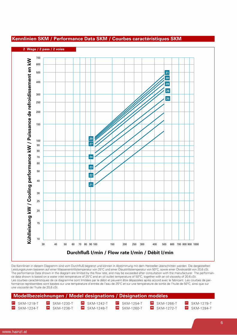
Geräteabmessungen SKM / Unit Dimensions SKM / Dimensions des appareils SKM
in mm / BSPP
EKM-1424
EKM-1430
EKM-1436
EKM-1442
EKM-1448
EKM-1454
EKM-1460
EKM-1466
EKM-1472
EKM-1478
EKM-1484
LO
N
N1
Q
M
A
GD
B
TE
F
"F"
I
K
1-Wege1-way1-voie
2-Wege2-way2-voie
4-Wege4-way4-voie
R
CD
CD
CD
A B
- Zu kühlendes Medium- Medium to be cooled- Médium à refroidir
- Gekühltes Medium- Cooled Medium- Médium refroidi
- Kühlwasser „Ein“- Cooling water inlet- Eau de refroidissement On
- Kühlwasser „Aus“- Cooling water outlet- Eau de refroidissement Off
A
B
C
D
U V W X Z
SAE 1“ 70 52,4 55 26,2 M10
SAE 1 1/4“ 79 58,7 68 30,2 M10
SAE 1 1/2“ 93 69,9 78 35,7 M12
SAE 2“ 102 77,8 90 42,9 M12
SAE 2 1/2“ 114 88,9 105 50,8 M12
SAE 3“ 135 106,4 130,6 62 M16
W
UV
Ø ZX
9
www.hainzl.at

Kennlinien EKM / Performance Data EKM / Courbes caractéristiques EKM
200 300 400 500 600 700 800 900 1000 1100 1200 1300 1400
50
0
100
150
200
250
300
350
400
450
500
550
600
650
700
750
800
850
900
950
Durchfluß l/min / Flow rate l/min / Débit l/min
Kü
hlle
istu
ng
kW
/ C
oo
ling
per
form
ance
kW
/ P
uis
san
ce d
e re
fro
idis
sem
ent
en k
W
5
1
2
3
4
6
10
7
8
9
11
Modellbezeichnungen / Model designations / Désignation modèlesEKM-1718-T-CNEKM-1724-T-CN2
1 EKM-1730-T-CNEKM-1736-T-CN
3
4
EKM-1742-T-CNEKM-1748-T-CN6
5 EKM-1754-T-CNEKM-1760-T-CN8
7 EKM-1766-T-CNEKM-1778-T-CN
9
10
EKM-1784-T-CN11
Die Kennlinien in diesem Diagramm sind vom Durchfluß begrenzt und können in Abstimmung mit dem Hersteller überschritten werden. Die dargestelltenLeistungskurven basieren auf einer Wasser eintritts temperatur von 25°C und einer Ölaustrittstemperatur von 50°C, sowie einer Ölviskosität von 20,6 cSt.The performance Data shown in the diagram are limited by the flow rate, and may be exceeded after consultation with the manufacturer. The performan-ce data shown is based on a water inlet temperature of 25°C and an oil outlet temperature of 50°C, together with an oil viscosity of 20.6 cSt.Les courbes caractéristiques de ce diagramme sont limitées par le débit et peuvent être dépassées après accord avec le fabricant. Les courbes de per-formance représen tées sont basées sur une température d’entrée de l’eau de 25°C et sur une température de sortie de l’huile de 50°C, ainsi que surune viscosité de l’huile de 20,6 cSt.
2 Wege / 2 pass / 2 voies
10
www.hainzl.at

Geräteabmessungen EKM / Unit Dimensions EKM / Dimensions des appareils EKM
in mm / BSPP
EKM-1724
EKM-1730
EKM-1736
EKM-1742
EKM-1748
EKM-1754
EKM-1760
EKM-1766
EKM-1772
EKM-1778
EKM-1784
B
368
521
673
826
978
1130
1283
1435
1587
1740
1892
D
214
214
214
214
214
214
214
214
214
214
214
A
706
859
1011
1164
1316
1468
1621
1773
1925
2078
2230
E
188
188
188
188
188
188
188
188
188
188
188
G
169
169
169
169
169
169
169
169
169
169
169
Q
∅ 16 x 38
∅ 16 x 38
∅ 16 x 38
∅ 16 x 38
∅ 16 x 38
∅ 16 x 38
∅ 16 x 38
∅ 16 x 38
∅ 16 x 38
∅ 16 x 38
∅ 16 x 38
F
SAE 3”
SAE 3”
SAE 3”
SAE 3”
SAE 3”
SAE 3”
SAE 3”
SAE 3”
SAE 3”
SAE 3”
SAE 3”
T
146
146
146
146
146
146
146
146
146
146
146
R
G 3”
G 3”
G 3”
G 3”
G 3”
G 3”
G 3”
G 3”
G 3”
G 3”
G 3”
M
G 2”
G 2”
G 2”
G 2”
G 2”
G 2”
G 2”
G 2”
G 2”
G 2”
G 2”
K
G 2 1/2”
G 2 1/2”
G 2 1/2”
G 2 1/2”
G 2 1/2”
G 2 1/2”
G 2 1/2”
G 2 1/2”
G 2 1/2”
G 2 1/2”
G 2 1/2”
N1
36
36
36
36
36
36
36
36
36
36
36
N
108
108
108
108
108
108
108
108
108
108
108
I
100
100
100
100
100
100
100
100
100
100
100
LO
N
N1
Q
M
A
GD
B
TE
F
"F"
I
K
1-Wege1-way1-voie
2-Wege2-way2-voie
4-Wege4-way4-voie
R
CD
CD
CD
A B
- Zu kühlendes Medium- Medium to be cooled- Médium à refroidir
- Gekühltes Medium- Cooled Medium- Médium refroidi
- Kühlwasser „Ein“- Cooling water inlet- Eau de refroidissement On
- Kühlwasser „Aus“- Cooling water outlet- Eau de refroidissement Off
A
B
C
D
O
210
210
210
210
210
210
210
210
210
210
210
L
178
178
178
178
178
178
178
178
178
178
178
U V W X Z
SAE 1“ 70 52,4 55 26,2 M10
SAE 1 1/4“ 79 58,7 68 30,2 M10
SAE 1 1/2“ 93 69,9 78 35,7 M12
SAE 2“ 102 77,8 90 42,9 M12
SAE 2 1/2“ 114 88,9 105 50,8 M12
SAE 3“ 135 106,4 130,6 62 M16
m2
14,77
18,85
22,65
26,70
30,52
34,55
38,40
42,25
46,28
50,12
54,15
W
UV
Ø ZX
11
www.hainzl.at

Bestellschlüssel / Ordering code / Code de commande
SS - EKM - 1036 - 6 - O - CN - R - W - SW - G 1 1/2“
Anschlußtyp / Connection typeType de raccordement
NPT = -SAE mit O-Ring,
wasserseite NPT/SAE with O-Ring, water side NPT/
SAE avec O-Ring, côté de l'eau NPT/ = S
BSPF = MSAE Flansch/SAE flange = FM
Baugröße / Unit size / Taille
R = Bypass-Ventil (teil öffnend) / Bypass valve (partly opened) / Soupape by-pass (partiellement ouverte)
RS = Bypass-Ventil (voll öffnend) / Bypass valve (fully opened) / Soupape by-pass (totalement ouverte)
Wasserrohre / Water tubes / Tuyeaux d’eauCN = Kupfer/Nickel / Copper/nickel / Cuivre/nickel CU = Kupfer / Copper / CuivreSS = Edelstahl / Stainless steel / Acier inox
Technische Daten / Technical data / Données techniques
Maximaler Betriebsdruck / Maximum operating Pressure / Pression maximale de service:Mantel / Shell / Manteau = 35 barRohre / Tubes / Tuyeaux = 16 bar
Betriebstemperatur / operating temperature / Températurede service: = 5 - 95 °C
Maximaler Durchfluß / Maximum flow rate / Débit maximal:
l/min Öl / Oil / huile Wasser / Water / eauMantel / Shell / Manteau Rohre / Tubes / Tuyeaux
Typ / Version / Version O T F
EKM - 500 75 60 30 -
EKM - 700 225 120 60 30
EKM - 1000 330 280 140 70
SKM - 1200 650 560 280 140
EKM - 1400 850 520 260 130
EKM - 1700 1200 980 490 245
Achtung: Unsachgemäßer Einbau kann zurBeschädigung des Kühlers führen.
Attention: Un montage erroné peut en traînerun endommagement du refroidisseur.
Caution: Incorrect installation can lead todamage to the cooler.
Vertrieb / Sales / Distribution
SW = Seewasser / Seawater / Eau de merSWBZ = Seewasser / Seawater / Eau de mer
Rotgußdeckel + ZinkanodeEnd cap gunmetal + zinc anode Caches gunmetal + anode de zink
SS = Deckel Edelstahl / End cap stainless steel / Caches acier inox
Rohrboden / Tube sheet / Plaques finalesW = Messing / naval brass / LaitonSS = Edelstahl / Stainless steel / Acier inox
G 1 1/2“= ölseitige Anschlüsse = Oil connections= raccordements d’huile
Kühlwasserführung / Cooling water connection systemRaccordement eau de refroidissementO = 1-Weg / 1-pass / 1-voieT = 2-Weg / 2-pass / 2-voies F = 4-Weg / 4-pass / 4-voies, Umlenksegmentabstand /Guide segment
setting / Ecart des segmentsdéflecteurs
Die technischen Angaben in diesem Datenblatt beziehen sich auf die beschrie-benen Betriebsbedingungen und Einsatzfälle. Bei abweichenden Betriebsbedin-gungen und Einsatzfällen wenden Sie sich bitte an uns.
Technische Änderungen vorbehalten. Bitte beachten Sie auch unsere Wartungs-und Bedienungsanleitung.
The technical data of this sheet is depending on the described operationalconditions and individual cases. At different operational conditions and differingindividual cases contact us.
Technical modifications reserved. Please also pay attention to our operationmanuals and maintenance documentations.
Typ500, 700, 1000, 1400, 1700 = E
1200 = S
KomplettkühlerComplete cooler
Refroidisseur complètEdelstahl / stainless steel
Acier inox (+ Alu-fins)
12
www.hainzl.at

- 5 –
HAINZL INDUSTRIESYSTEME GMBH
Industriezeile 56, A-4021 Linz
Austria
Tel: +43 (0) 732-7892-334
Fax: +43 (0) 732-7892-191
E-Mail: [email protected]
www.hainzl.at
Recommended