- 1 - Advanced Robotics (RSJ)
Self-rappelling Robot System for Inspection And Reconnaissance in Search and Rescue Applications
HAGEN SCHEMPFAutomatika, Inc.137 Delta Drive
Pittsburgh, PA 15238, [email protected]
Abstract
A new type of self-rappelling search-and-rescue robot with chassis articulation, dubbedSPIDAR, has been developed and tested for use by first-responders. SPIDAR is built arounda set of articulating body-sections, running a modular running-gear configuration (wheels,legs, tracks, etc.) to allow for maximum terrainability in chaotic collapsed urban structures.The on-board tether-system allows for continuous powering and real-time data/video feed-back. The tether serves as a tensile member that allows for rappelling and winching therobot into and out of precipices and crevasses, with a range of up to 30 meters. The systemis deployable and operable by a single person off a remote console. This paper describesthe overall system design and prototype efforts to date, including testing on critical ele-ments of the system and field-testing in a collapsed structure environment. Future testing isenvisioned with first responders to further evaluate the prototype design and collect data forfuture improvements. The vehicle design was shown to be effective for terrainability andaccess into small/vertical spaces, but future improvements in key areas (tethering, displays,etc.) are recommended to improve system performance. The project is being funded byDARPA (Defense Advanced Projects Agency) with the intent to transfer technologies fromthe military domain to the civilian first-responder application markets.
Keywords - robot, search, rescue, tether, rappel, locomotion
1. INTRODUCTIONThe urban environment represents the most challenging application-arena for reconnaissance and
recovery robots, irrespective of whether the structures are in pristine, or even worse, collapsed and
crumbled configurations. The ability to access constrained and often layered environments (due to floor-
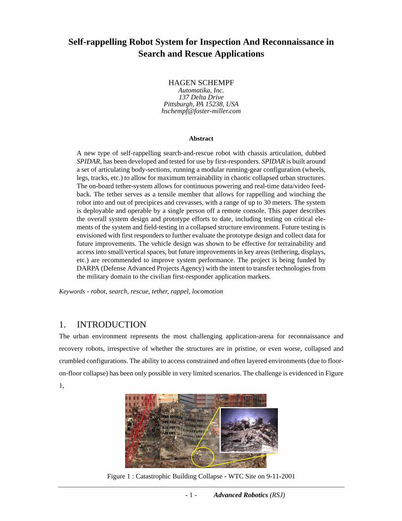
on-floor collapse) has been only possible in very limited scenarios. The challenge is evidenced in Figure
1,
Figure 1 : Catastrophic Building Collapse - WTC Site on 9-11-2001
- 2 - Advanced Robotics (RSJ)
SPIDAR: Self-rappelling Robot System for Inspection And Reconnaissance in Search and Rescue Applications
which clearly shows the access and locomotion challenges that ‘mechanized’ rescue devices would face.
Whether collapses are due to man-made or natural causes, the key questions that need to be answered,
especially in the first 24 to 72 hours, are still the same: Are there any survivors and where are they? What
is the structural integrity of the structure? Are there any hazardous conditions within the structure not
clearly visible to first-responders?
Only since the 9/11 attack on the Pentagon and World Trade Center (WTC), have robots been used in
such applications (CRASAR, DARPA, etc.) [1][2][4]. Even then, their application was fairly limited [8].
However, the use of robots is projected to grow once the technology becomes more mature, accepted,
and more capable. Currently, the use of larger, wirelessly-controlled and battery-powered platforms
limits the use of robots in cluttered, confined and long-duration applications. Tethered platforms (such
as the Innuktun line of crawlers) have proved to be extremely valuable and usable, but since their spool-
point is at the base, rather than at the robot, the range of deployment is limited, or restricted to fairly
accessible (lower frictional drag) and more obstacle-free (no chance of snagging) situations.
2. REQUIREMENTS AND SPECIFICATIONSIn order to develop a more capable disaster-response robotic system for use in confined collapsed-
structure access for survivor search, site-investigation and site-assessment, the following key attributes
are deemed essential (in no particular order of importance):
• Provide for a small and light footprint • Allow for long-term deployment of at least 12 hours • Be capable of carrying crucial sensor-modalities (visual, chemical, etc.) • Be capable of accessing and climbing up/down convoluted and confined spaces • Be capable of real-time control of ‘buried’ ranges no less than 30m • Be simple to use off a limited-function controller with a user-friendly GUI (Graphical User
Interface) • Be designed for rugged use and be affordable for civil-defense entities
We conducted a technology search that looked at numerous robotics platforms (commercial and R&D
platforms available through IRobot, Foster-Miller, Remotec, Innuktun, etc.)[3][5], and determined that
none of these systems were designed explicitly with the collapsed-building internal-use scenario in
mind. Most systems had constraints in terms of size, weight, endurance, locomotion capability, etc.
[6][9].
These shortcomings needed to be overcome before a more usable and capable platform could be offered
to first responders - one they would be willing to rely upon and use. We believe that SPIDAR, a new
- 3 - Advanced Robotics (RSJ)
SPIDAR: Self-rappelling Robot System for Inspection And Reconnaissance in Search and Rescue Applications
representative for self-tethering platforms [10][11], with articulated frame/suspension and
reconfigurable running-gear (wheels, legs, treads) [7], has the potential to overcome the main drawbacks
of current systems. In addition to its off-the-vehicle tether-spooling (laying/spooling down/up the
tether), with data/power integral for long-duration missions, the vehicle will need to be a capable of
deploying visual (visible and IR) and other chemical sensors (CO2 emissions, NH3-detection, SpO2
blood-oxygen content, etc.) into real-world disaster scenarios.
Based on interactions with experts in the field of search-and-rescue, it became clear that many design
decisions hinged on the trade-offs related to (i) system size to access the smallest possible openings, (ii)
the need to overcome large obstacles (rubble) which is directly related to size, and (iii) the need to be
able to adapt to the unpredictable terrain type and the need to probe to varying depths into collapsed
structures and other locations (sewers, caves, ducts, etc.). The design trade-offs determined early on
what size (tiny, small, medium or large) platform was utilized (trading off access-capability against
obstacle-climbing capability)1, and what operator-selectable features were to be included in the design,
to optimize terrain-handling abilities (locomotor-dependent)2 and probing-depth (related to tether-
length primarily if access is guaranteed)3. The net outcome was the high-level performance
requirements shown in Table 1, which were then tuned into system specifications for the prototype (see
Table 2).
Table 1 : SPIDAR Performance Requirements
1. A small/tiny platform capable of accessing a small opening is not as capable if it can not overcome large (w.r.t. the vehicle size) obstacles (internal and not visible externally) in its way, rendering its size-attribute unusable.
2. There is no single locomotor capable of handling all terrain types - these terrain types are varied and not known beforehand and thus providing the operator with the ability to adapt on-site is an advantage over hard-designed (non-modular) systems.
3. The ability to decide on-site (by the operator) what vehicle configuration is best used to minimize size and weight yet be able to probe deep into the ‘buried’ structure, is another modularity attribute that provides substantial advantages over other more fixed-design non-modular systems available today or under consideration/design.
CRITERIA VALUE DESCRIPTION OR INTERPRETATIONSize Small As non-bulky as possible;
Small enough to fit through tight man-inaccessible spacesWeight Light Single-person one-hand hanging-portable
Terrain Ability Extreme
Use of retractable tensile member for climbing/rappelling; Forward/reverse in extreme terrain;Use in complex interconnected (collapsed) man-made spaces; Able to climb over/onto varying/large size obstacles, into/though rubble, sewers, tunnels, ducts
Tether System
Multiple Strength-member, power-supply & communications linkRugged Sharp-bend (under load) survival w/o loss & fatigue-enduranceSensing Tether-tension and pay-out distance
Endurance Maximize Use of long-duration power source; on- or off-boardRange 30m+ At least 30m if not more
Integration Various On-board sensing, communications & processingLocomotor Various Wheels or Legs

- 4 - Advanced Robotics (RSJ)
SPIDAR: Self-rappelling Robot System for Inspection And Reconnaissance in Search and Rescue Applications
Table 2 : SPIDAR System Specifications
Command &Control
(C&C)
As needed
Handling all sensory feedback and control data
CPU Processing all data and real-time control of all actuationControl Unit - Operator video display
Interface Power and Communications Interface to the tetherSensor
PayloadVideo Cameras (3 - front/left/right) & lights for 360o ‘surround’-visionSound Microphones (3 - front/left/right)
Application Areas Collapsed Buildings, Caves, Sewers, Ducts, Contaminated
Size 71 L x 41 W x 10 H [cm3] Weight < 12.5 kgs
Speed < 0.3 m/sec [1.13 km/hr.] Power 120 VAC, 4.4A
Range 30 - 60 or morea meters
a. achieved through the in-line coupling of tether-module range-extender units, which consist of a separately-housed replicaof a TMS (as many as needed to achieve a specific range)
Operations Invertibleb
b. can run right-side up or inverted
Tether Power, Data & Tensilec
c. teflon-jacketed multi-conductor STP copper cabling with filler & Kevlar tensile fiber-mesh
Communications 100 Mb Ethernetd
d. digital & bi-directional; implementing reduced-set TCP protocol as per 802.3 standard
Video Color, 15 fpse
e. digital MPEG-4 compressed
Lights White LEDs
Ruggedness 10g impactsf
f. achieved through isolation and encapsulation - proprietary method applied & proven in Dragon Runner
Immersion IP65 rated
TensionControl
Tension-relief capstan-drive with slip-clutches and thresholded directional motor current & torque controller with tension-saturation relief
Electronics Arch. Off-board WIN-based embedded PC with an on-board 32-bit LINUX-based SBC with on-board 8-bit distributed CPUs with real-time software kernel
Running Gear Wheels, Tracks, Legs (ellipto, spoke) & any hybrid combination
Sensors Microphones (2), Speakers (2), Low-lux CMOS Cameras (3+) with 120o FOV Lens - full 360o sphericalg & pointingh
g. achieved thru multi-camera views with digital multi-view cycle-thru updateh. through the use of pitcheable posture-, head- and camera-modules
Locomotion Any surface, vertical climbing/descent; tether assisted
Articulation Postureable chassis for extreme climbing, ledge handling & inspectioni
i. both chassis, sensor-head and camera-module are independently postureable to allow up/down climbing and downwardcrack- and edge-inspection
OCS Controller Mini-briefcase OCSj with optional handcontroller
j. highly portable and includes a tether-termination anchoring setup to relief tether-tension to the OCS
CRITERIA VALUE DESCRIPTION OR INTERPRETATION

- 5 - Advanced Robotics (RSJ)
SPIDAR: Self-rappelling Robot System for Inspection And Reconnaissance in Search and Rescue Applications
3. SYSTEM DESIGNThis section describes the current design for the SPIDAR system. It addresses the main specific
subsystems and overall system descriptors that were deemed essential and were identified as main
design drivers.
Overview
An overall perspective of the vehicle platform, is shown in Figure 2, depicting the multi-segmented, all-
wheel drive (AWD) multi running-gear configuration (shown here with wheels) system design:
Figure 2 : Overall external CAD view of the SPIDAR vehicle platform
Notice that the overall design of the system allows the platform to be fully invertible and operate in either
orientation - video imagery and driving-commands are automatically flipped (based on accelerometer
feedback), and the sensor-head on the platform can rotate so as to allow the same field-of-views
irrespective of the (rightside-up/upside-down) orientation of the platform itself. In other words it does
not matter how the platform lands or winds up oriented when being deployed. The size of the platform
is depicted in Figure 3 and exhibits a net volume of 0.018 m3 and a total weight of 11.2 kg.
Figure 3 : Overall SPIDAR baseline vehicle platform dimensions

- 6 - Advanced Robotics (RSJ)
SPIDAR: Self-rappelling Robot System for Inspection And Reconnaissance in Search and Rescue Applications
The vehicle chassis is split to allow for posturing of the frontal section for improved climbing and
sensory inspection activities. The running gear is exchangeable with different configurations such as
wheels, tracks and legs.
The main elements of the SPIDAR system are all depicted in a top-shell-off exploded view in Figure 4,
which are detailed in the following subsections.
Figure 4 : Internal view of the main vehicle platform subsystems
Mono-coque Chassis and Articulation (Chassis & Sensors)
The housing/shell (also termed chassis) is the structural element of the vehicle. It was designed to be
mirror-image identical (top/bottom) so that it can be injection-molded in a fiber-reinforced thermoplastic
to endure abuse and be light and low cost to reproduce or replace. The shell is split into a fixed-axle rear
compartment and an actively postureable front-end - this is to allow for larger-sized obstacle climbing
ability (ledges, beams, boulders, etc.) and controlled transitions from vertical to horizontal during
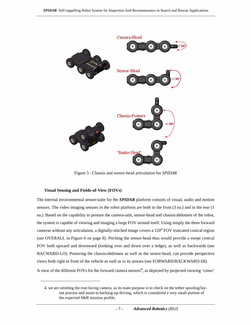
climbing and rappelling motions. Articulation of the sensor-head allows for the operator to view the
entire surroundings of the vehicle under real-time conditions. A visualization for the articulation of the
chassis-abdomen and the sensor-head, are shown in Figure 5.
Sensor-Head
(TMS)
Chassis
Wheels
3x3 AWD
Posturable Chassis/Abdomen
Tether Management System
Drivetrain
- 7 - Advanced Robotics (RSJ)
SPIDAR: Self-rappelling Robot System for Inspection And Reconnaissance in Search and Rescue Applications
Figure 5 : Chassis and sensor-head articulation for SPIDAR
Visual Sensing and Fields-of-View (FOVs)
The internal environmental sensor-suite for the SPIDAR platform consists of visual, audio and motion
sensors. The video imaging sensors in the robot platform are both in the front (3 ea.) and in the rear (1
ea.). Based on the capability to posture the camera-unit, sensor-head and chassis/abdomen of the robot,
the system is capable of viewing and imaging a large FOV around itself. Using simply the three forward
cameras without any articulation, a digitally-stitched image covers a 120o FOV truncated conical region
(see OVERALL in Figure 6 on page 8). Pitching the sensor-head thus would provide a swept conical
FOV both upward and downward (looking over and down over a ledge), as well as backwards (see
BACWARD-LO). Posturing the chassis/abdomen as well as the sensor-head, can provide perspective
views both right in front of the vehicle as well as to its arrears (see FORWARD/BACKWARD-HI).
A view of the different FOVs for the forward camera sensors4, as depicted by projected viewing ‘cones’
4. we are omitting the rear-facing camera, as its main purpose is to check on the tether spooling/lay-out process and assist in backing-up driving, which is considered a very small portion of the expected S&R mission profile.

- 8 - Advanced Robotics (RSJ)
SPIDAR: Self-rappelling Robot System for Inspection And Reconnaissance in Search and Rescue Applications
under different camera, sensor-head and chassis articulation configurations as discussed above, are
shown in Figure 6.
Figure 6 : SPIDAR robot platform FOV configurations for forward camera(s)
Vehicle Chassis - Integration & Posture Articulation
The main chassis element of the SPIDAR platform houses the main drive-motors and reduction
gearboxes, as well as all the transfer drives and the chassis-posture drivetrain. The electronics to drive
the motor power-stages (ESCs) and the local low-level 8-bit control microprocessors are mounted in a
heatsink stack, which is sandwiched between the two thermoplastic housing shell-halves. An assembled,
internal and close-up view of the different elements within the (abdomen) chassis section of the SPIDAR
vehicle, are shown in Figure 7.
Figure 7 : SPIDAR vehicle (abdomen) chassis packaging and posture drive details
- 9 - Advanced Robotics (RSJ)
SPIDAR: Self-rappelling Robot System for Inspection And Reconnaissance in Search and Rescue Applications
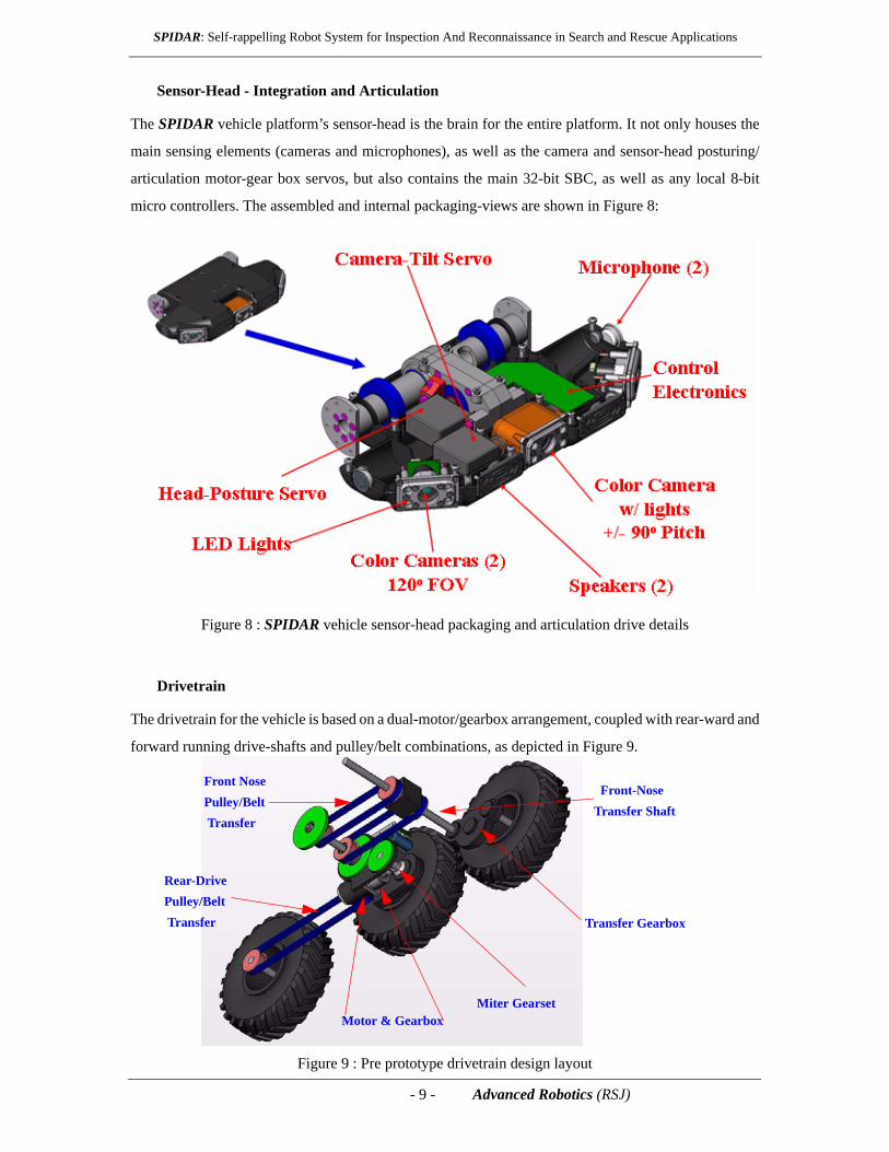
Sensor-Head - Integration and Articulation
The SPIDAR vehicle platform’s sensor-head is the brain for the entire platform. It not only houses the
main sensing elements (cameras and microphones), as well as the camera and sensor-head posturing/
articulation motor-gear box servos, but also contains the main 32-bit SBC, as well as any local 8-bit
micro controllers. The assembled and internal packaging-views are shown in Figure 8:
Figure 8 : SPIDAR vehicle sensor-head packaging and articulation drive details
Drivetrain
The drivetrain for the vehicle is based on a dual-motor/gearbox arrangement, coupled with rear-ward and
forward running drive-shafts and pulley/belt combinations, as depicted in Figure 9.
Figure 9 : Pre prototype drivetrain design layout
Motor & Gearbox
Transfer Gearbox
Front NosePulley/Belt Transfer
Rear-DrivePulley/Belt Transfer
Front-NoseTransfer Shaft
Miter Gearset
- 10 - Advanced Robotics (RSJ)
SPIDAR: Self-rappelling Robot System for Inspection And Reconnaissance in Search and Rescue Applications
This design allows for the minimal-weight implementation of skid-steer drive in a multi-wheeled
articulated-frame vehicle. An additional motor/gearbox/miter-gear drivetrain is used to articulate the
front housing of the vehicle, achieving a postureable chassis/abdomen (see Figure 5). Miniaturized
servo-actuators are used to provide articulation for the sensor-head, as well as the centrally-located
forward-looking pitch-camera (driving and up-close inspection), to increase the FOV in as compact a
platform-design as possible.
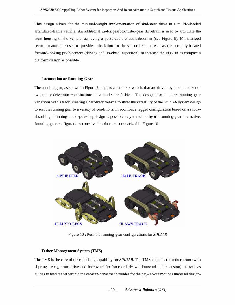
Locomotion or Running-Gear
The running gear, as shown in Figure 2, depicts a set of six wheels that are driven by a common set of
two motor-drivetrain combinations in a skid-steer fashion. The design also supports running gear
variations with a track, creating a half-track vehicle to show the versatility of the SPIDAR system design
to suit the running gear to a variety of conditions. In addition, a legged configuration based on a shock-
absorbing, climbing-hook spoke-leg design is possible as yet another hybrid running-gear alternative.
Running-gear configurations conceived to-date are summarized in Figure 10.
Figure 10 : Possible running-gear configurations for SPIDAR
Tether Management System (TMS)
The TMS is the core of the rappelling capability for SPIDAR. The TMS contains the tether-drum (with
sliprings, etc.), drum-drive and levelwind (to force orderly wind/unwind under tension), as well as
guides to feed the tether into the capstan-drive that provides for the pay-in/-out motions under all design-
- 11 - Advanced Robotics (RSJ)
SPIDAR: Self-rappelling Robot System for Inspection And Reconnaissance in Search and Rescue Applications
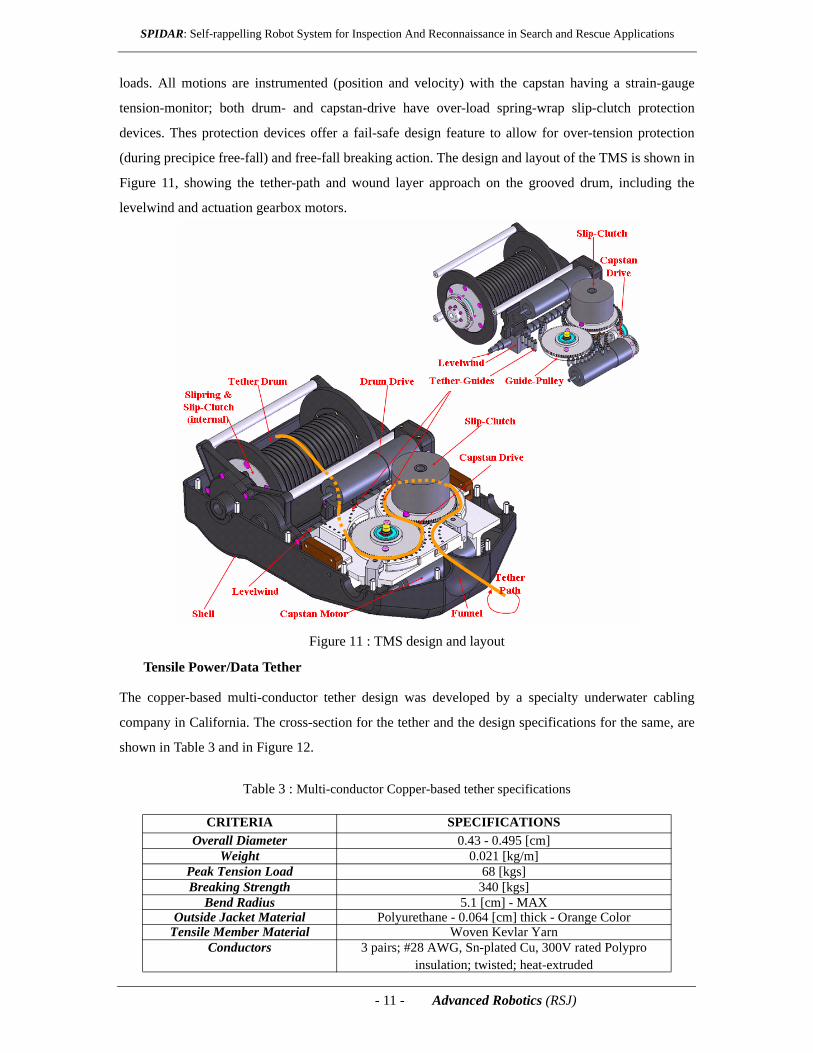
loads. All motions are instrumented (position and velocity) with the capstan having a strain-gauge
tension-monitor; both drum- and capstan-drive have over-load spring-wrap slip-clutch protection
devices. Thes protection devices offer a fail-safe design feature to allow for over-tension protection
(during precipice free-fall) and free-fall breaking action. The design and layout of the TMS is shown in
Figure 11, showing the tether-path and wound layer approach on the grooved drum, including the
levelwind and actuation gearbox motors.
Figure 11 : TMS design and layout
Tensile Power/Data Tether
The copper-based multi-conductor tether design was developed by a specialty underwater cabling
company in California. The cross-section for the tether and the design specifications for the same, are
shown in Table 3 and in Figure 12.
Table 3 : Multi-conductor Copper-based tether specifications
CRITERIA SPECIFICATIONSOverall Diameter 0.43 - 0.495 [cm]
Weight 0.021 [kg/m]Peak Tension Load 68 [kgs]Breaking Strength 340 [kgs]
Bend Radius 5.1 [cm] - MAXOutside Jacket Material Polyurethane - 0.064 [cm] thick - Orange Color
Tensile Member Material Woven Kevlar YarnConductors 3 pairs; #28 AWG, Sn-plated Cu, 300V rated Polypro
insulation; twisted; heat-extruded
- 12 - Advanced Robotics (RSJ)
SPIDAR: Self-rappelling Robot System for Inspection And Reconnaissance in Search and Rescue Applications
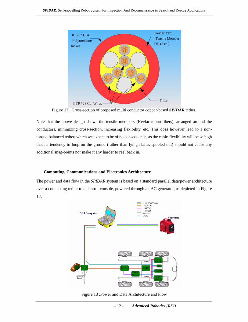
Figure 12 : Cross-section of proposed multi conductor copper-based SPIDAR tether.
Note that the above design shows the tensile members (Kevlar mono-fibers), arranged around the
conductors, minimizing cross-section, increasing flexibility, etc. This does however lead to a non-
torque-balanced tether, which we expect to be of no consequence, as the cable-flexibility will be so high
that its tendency to loop on the ground (rather than lying flat as spooled out) should not cause any
additional snag-points nor make it any harder to reel back in.
Computing, Communications and Electronics Architecture
The power and data flow in the SPIDAR system is based on a standard parallel data/power architecture
over a connecting tether to a control console, powered through an AC generator, as depicted in Figure
13:
Figure 13 :Power and Data Architecture and Flow
3 TP #28 Cu. Wires
0.170” DIA Kevlar YarnTensile Member
Fill (3 ea.)Polyurethane
Jacket
Filler
- 13 - Advanced Robotics (RSJ)
SPIDAR: Self-rappelling Robot System for Inspection And Reconnaissance in Search and Rescue Applications
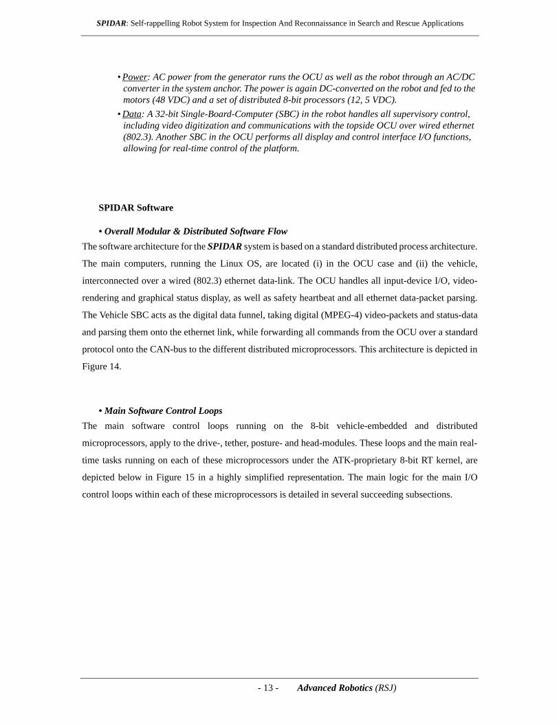
• Power: AC power from the generator runs the OCU as well as the robot through an AC/DC converter in the system anchor. The power is again DC-converted on the robot and fed to the motors (48 VDC) and a set of distributed 8-bit processors (12, 5 VDC).
• Data: A 32-bit Single-Board-Computer (SBC) in the robot handles all supervisory control, including video digitization and communications with the topside OCU over wired ethernet (802.3). Another SBC in the OCU performs all display and control interface I/O functions, allowing for real-time control of the platform.
SPIDAR Software
• Overall Modular & Distributed Software FlowThe software architecture for the SPIDAR system is based on a standard distributed process architecture.
The main computers, running the Linux OS, are located (i) in the OCU case and (ii) the vehicle,
interconnected over a wired (802.3) ethernet data-link. The OCU handles all input-device I/O, video-
rendering and graphical status display, as well as safety heartbeat and all ethernet data-packet parsing.
The Vehicle SBC acts as the digital data funnel, taking digital (MPEG-4) video-packets and status-data
and parsing them onto the ethernet link, while forwarding all commands from the OCU over a standard
protocol onto the CAN-bus to the different distributed microprocessors. This architecture is depicted in
Figure 14.
• Main Software Control LoopsThe main software control loops running on the 8-bit vehicle-embedded and distributed
microprocessors, apply to the drive-, tether, posture- and head-modules. These loops and the main real-
time tasks running on each of these microprocessors under the ATK-proprietary 8-bit RT kernel, are
depicted below in Figure 15 in a highly simplified representation. The main logic for the main I/O
control loops within each of these microprocessors is detailed in several succeeding subsections.

- 14 - Advanced Robotics (RSJ)
SPIDAR: Self-rappelling Robot System for Inspection And Reconnaissance in Search and Rescue Applications
Figure 14 : Overall high-level software architecture and task-flow diagram for the SPIDAR system
Figure 15 : Four main control loops running aboard the SPIDAR platform
OCU
Linux CommsParsing
OCU I/O OCU
Display &Overlay
SafetyHeartbeat
DataHandling & Storage
SBC
QNX
MPEG-4 Video Digitizer
ENetTCP/IP
TCP/IP CommsParsing
CAN BusProtocol
VideoCompr.
HealthMonitoring
SafetyHeartbeat
Message Traffic
8-bit μP
RTK
DRIVE MODULE
CommsParsing
PWMControl
Motor Fdbk
Bus A
rbitr
ator
8-bit μP
RTK
TMS MODULE
CommsParsing
Tension &
Bus A
rbitr
ator
8-bit μP
RTK
SENSOR MODULE
CommsParsing
PWMArticulation
Video Switch
Bus A
rbitr
ator
Audio & Motion Fdbk
Capstan PWM
Payout Fdbk
Drive PWM
Video Source
8-bit μP
RTK
POSTURE MODULE
CommsParsing Posture
PWM
Bus A
rbitr
ator
PWMControl
Motor Fdbk
Kernel/taskswitcherCAN Interface
Variable Reportand Storage
Left MotorControl Loop
Power Control
Right MotorControl Loop
Motor VelocitySensor Interfaces
Kernel/taskswitcher
Tether MotorControl Loop
AccelerometerInterface
Serial Interface
Load CellInterface
Variable Reportand Storage
Tension MotorControl Loop
Power Control
Hitch MotorControl Loop
Motor VelocitySensor Interfaces
Kernel/taskswitcher
Nose MotorControl Loop
CAN Interface
Variable Reportand Storage
Abdomen MotorControl Loop
Power Control
Head MotorControl Loop
Motor VelocitySensor Interfaces
Kernel/taskswitcherCAN Interface
Variable Reportand Storage
Light Control
SBC Interface
DRIVE
TETHER
POSTURE
HEAD
Kernel/taskswitcherCAN Interface
Variable Reportand Storage
Left MotorControl Loop
Power Control
Right MotorControl Loop
Motor VelocitySensor Interfaces
Kernel/taskswitcher
Tether MotorControl Loop
AccelerometerInterface
Serial Interface
Load CellInterface
Variable Reportand Storage
Tension MotorControl Loop
Power Control
Hitch MotorControl Loop
Motor VelocitySensor Interfaces
Kernel/taskswitcher
Nose MotorControl Loop
CAN Interface
Variable Reportand Storage
Abdomen MotorControl Loop
Power Control
Head MotorControl Loop
Motor VelocitySensor Interfaces
Kernel/taskswitcherCAN Interface
Variable Reportand Storage
Light Control
SBC Interface
DRIVE
TETHER
POSTURE
HEAD
- 15 - Advanced Robotics (RSJ)
SPIDAR: Self-rappelling Robot System for Inspection And Reconnaissance in Search and Rescue Applications
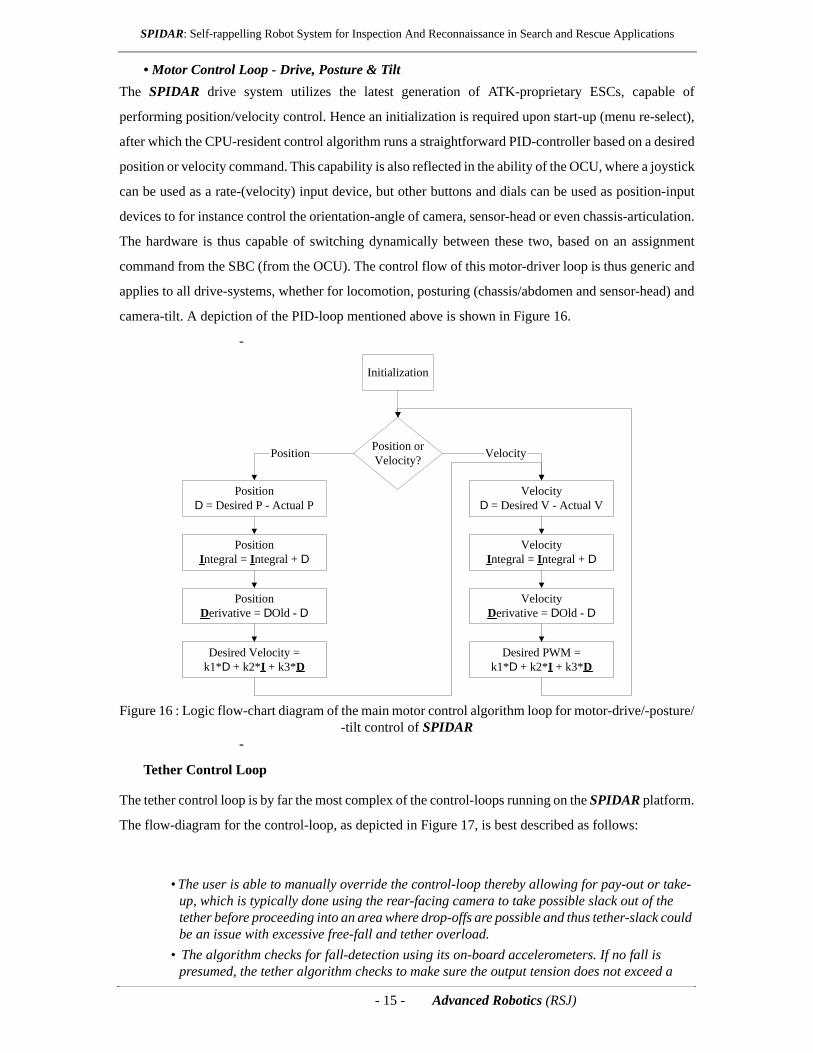
• Motor Control Loop - Drive, Posture & TiltThe SPIDAR drive system utilizes the latest generation of ATK-proprietary ESCs, capable of
performing position/velocity control. Hence an initialization is required upon start-up (menu re-select),
after which the CPU-resident control algorithm runs a straightforward PID-controller based on a desired
position or velocity command. This capability is also reflected in the ability of the OCU, where a joystick
can be used as a rate-(velocity) input device, but other buttons and dials can be used as position-input
devices to for instance control the orientation-angle of camera, sensor-head or even chassis-articulation.
The hardware is thus capable of switching dynamically between these two, based on an assignment
command from the SBC (from the OCU). The control flow of this motor-driver loop is thus generic and
applies to all drive-systems, whether for locomotion, posturing (chassis/abdomen and sensor-head) and
camera-tilt. A depiction of the PID-loop mentioned above is shown in Figure 16.
-
Figure 16 : Logic flow-chart diagram of the main motor control algorithm loop for motor-drive/-posture/-tilt control of SPIDAR
-
Tether Control Loop
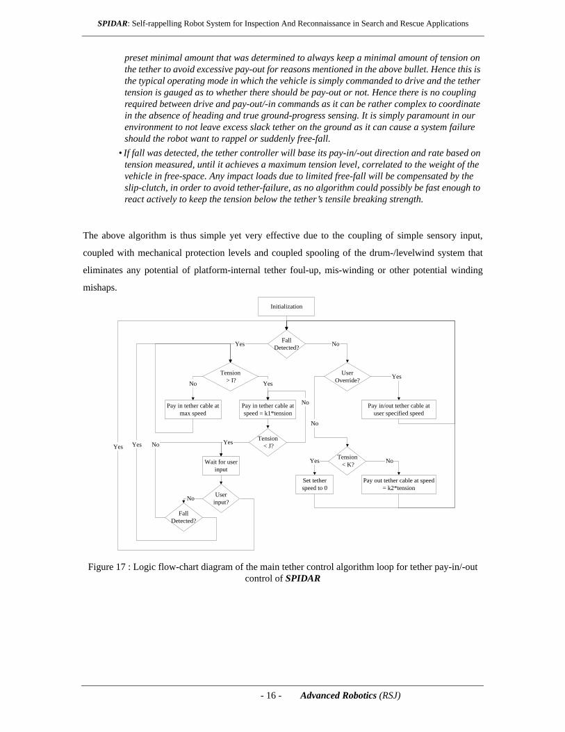
The tether control loop is by far the most complex of the control-loops running on the SPIDAR platform.
The flow-diagram for the control-loop, as depicted in Figure 17, is best described as follows:
• The user is able to manually override the control-loop thereby allowing for pay-out or take-up, which is typically done using the rear-facing camera to take possible slack out of the tether before proceeding into an area where drop-offs are possible and thus tether-slack could be an issue with excessive free-fall and tether overload.
• The algorithm checks for fall-detection using its on-board accelerometers. If no fall is presumed, the tether algorithm checks to make sure the output tension does not exceed a
Initialization
Position orVelocity?Position Velocity
PositionD = Desired P - Actual P
Desired Velocity =k1*D + k2*I + k3*D
PositionIntegral = Integral + D
PositionDerivative = DOld - D
VelocityD = Desired V - Actual V
Desired PWM =k1*D + k2*I + k3*D
VelocityIntegral = Integral + D
VelocityDerivative = DOld - D
- 16 - Advanced Robotics (RSJ)
SPIDAR: Self-rappelling Robot System for Inspection And Reconnaissance in Search and Rescue Applications
preset minimal amount that was determined to always keep a minimal amount of tension on the tether to avoid excessive pay-out for reasons mentioned in the above bullet. Hence this is the typical operating mode in which the vehicle is simply commanded to drive and the tether tension is gauged as to whether there should be pay-out or not. Hence there is no coupling required between drive and pay-out/-in commands as it can be rather complex to coordinate in the absence of heading and true ground-progress sensing. It is simply paramount in our environment to not leave excess slack tether on the ground as it can cause a system failure should the robot want to rappel or suddenly free-fall.
• If fall was detected, the tether controller will base its pay-in/-out direction and rate based on tension measured, until it achieves a maximum tension level, correlated to the weight of the vehicle in free-space. Any impact loads due to limited free-fall will be compensated by the slip-clutch, in order to avoid tether-failure, as no algorithm could possibly be fast enough to react actively to keep the tension below the tether’s tensile breaking strength.
The above algorithm is thus simple yet very effective due to the coupling of simple sensory input,
coupled with mechanical protection levels and coupled spooling of the drum-/levelwind system that
eliminates any potential of platform-internal tether foul-up, mis-winding or other potential winding
mishaps.
Figure 17 : Logic flow-chart diagram of the main tether control algorithm loop for tether pay-in/-out control of SPIDAR
Initialization
Tension < K?Yes No
Set tetherspeed to 0
FallDetected?Yes No
Pay in tether cable atmax speed
Tension > I? YesNo
UserOverride? Yes
No
Pay in tether cable atspeed = k1*tension
Tension < J?
No
Yes
Wait for userinput
Userinput?No
Yes
Pay out tether cable at speed= k2*tension
Pay in/out tether cable atuser specified speed
FallDetected?
NoYes
- 17 - Advanced Robotics (RSJ)
SPIDAR: Self-rappelling Robot System for Inspection And Reconnaissance in Search and Rescue Applications
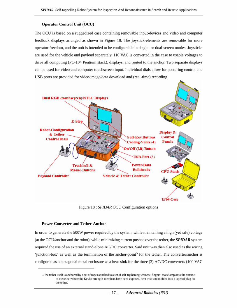
Operator Control Unit (OCU)
The OCU is based on a ruggedized case containing removable input-devices and video and computer
feedback displays arranged as shown in Figure 18. The joystick-elements are removable for more
operator freedom, and the unit is intended to be configurable in single- or dual-screen modes. Joysticks
are used for the vehicle and payload separately. 110 VAC is converted in the case to usable voltages to
drive all computing (PC-104 Pentium stack), displays, and routed to the anchor. Two separate displays
can be used for video and computer touchscreen input. Individual dials allow for posturing control and
USB ports are provided for video/image/data download and (real-time) recording.
Figure 18 : SPIDAR OCU Configuration options
Power Converter and Tether-Anchor
In order to generate the 500W power required by the system, while maintaining a high (yet safe) voltage
(at the OCU/anchor and the robot), while minimizing current pushed over the tether, the SPIDAR system
required the use of an external stand-alone AC/DC converter. Said unit was then also used as the wiring
‘junction-box’ as well as the termination of the anchor-point5 for the tether. The converter/anchor is
configured as a hexagonal metal enclosure as a heat-sink for the three (3) AC/DC converters (100 VAC
5. the tether itself is anchored by a set of ropes attached to a set of self-tigthening ‘chinese-fingers’ that clamp onto the outside of the tether where the Kevlar strength-members have been exposed, bent over and molded into a tapered plug on the tether.

- 18 - Advanced Robotics (RSJ)
SPIDAR: Self-rappelling Robot System for Inspection And Reconnaissance in Search and Rescue Applications
from the generator to 300 VDC) to feed the OCU and the robot with power. A set of end-caps with a fan
provide for forced convective cooling across an intake/exhaust to allow operation in 120oF ambient air
and direct sunlight. An image of the assembled and exploded-view power-converter/anchor is depicted
in Figure 19.
Figure 19 : Assembled and exploded view of the SPIDAR AC/DC Converter unit and anchor-interface
Deployment and Operations
The SPIDAR system, including the vehicle platform, the AC generator and converter/anchor, as well as
the small light-weight OCU, are designed to be deployed (carried on-site) by a single operator, as
depicted in Figure 206.
Figure 20 : Deployment of SPIDAR by a single person into multiple civil-defense/military missions
6. Note that the notion is that SPIDAR can be deployed into military as well as civil-defense missions, capable of accessing and inspecting a variety of arenas requiring a rappelling robot system (see Figure 20).
AC GenSet
OCS
SPIDAR
First Responder
AC GenSet
OCS
SPIDAR
First Responder
Disaster ResponseMilitary Recon
- 19 - Advanced Robotics (RSJ)
SPIDAR: Self-rappelling Robot System for Inspection And Reconnaissance in Search and Rescue Applications
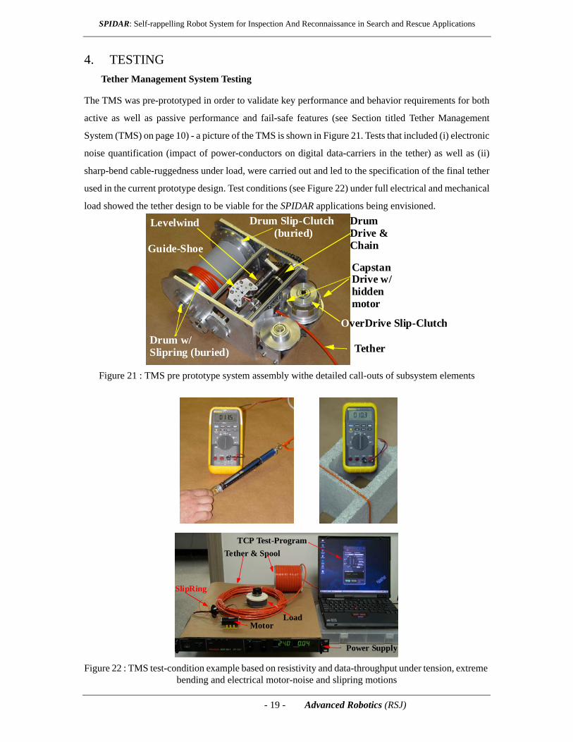
4. TESTINGTether Management System Testing
The TMS was pre-prototyped in order to validate key performance and behavior requirements for both
active as well as passive performance and fail-safe features (see Section titled Tether Management
System (TMS) on page 10) - a picture of the TMS is shown in Figure 21. Tests that included (i) electronic
noise quantification (impact of power-conductors on digital data-carriers in the tether) as well as (ii)
sharp-bend cable-ruggedness under load, were carried out and led to the specification of the final tether
used in the current prototype design. Test conditions (see Figure 22) under full electrical and mechanical
load showed the tether design to be viable for the SPIDAR applications being envisioned.
Figure 21 : TMS pre prototype system assembly withe detailed call-outs of subsystem elements
Figure 22 : TMS test-condition example based on resistivity and data-throughput under tension, extreme bending and electrical motor-noise and slipring motions
Tether
Capstan
DrumDrive &Chain
Drive w/
OverDrive Slip-Clutch
Levelwind
Guide-Shoe
Drum w/Slipring (buried)
hiddenmotor
Drum Slip-Clutch (buried)
SlipRing
Tether & SpoolTCP Test-Program
MotorLoad
Power Supply
SlipRing
Tether & SpoolTCP Test-Program
MotorLoad
Power Supply

- 20 - Advanced Robotics (RSJ)
SPIDAR: Self-rappelling Robot System for Inspection And Reconnaissance in Search and Rescue Applications
Integrated System Functional Testing
The complete system prototype, consisting of the vehicle, anchor, OCU and power-generator was used
for the functional system checkout - see Figure 23. The ability to configure the chassis and sensor-head
and the ability to control the locomotion and tethering jointly, was proven out in the laboratory.
Figure 23 : Prototype SPIDAR system including vehicle, anchor, OCU and generator
Figure 24 : Vehicle Posturing and articulation capability evaluation
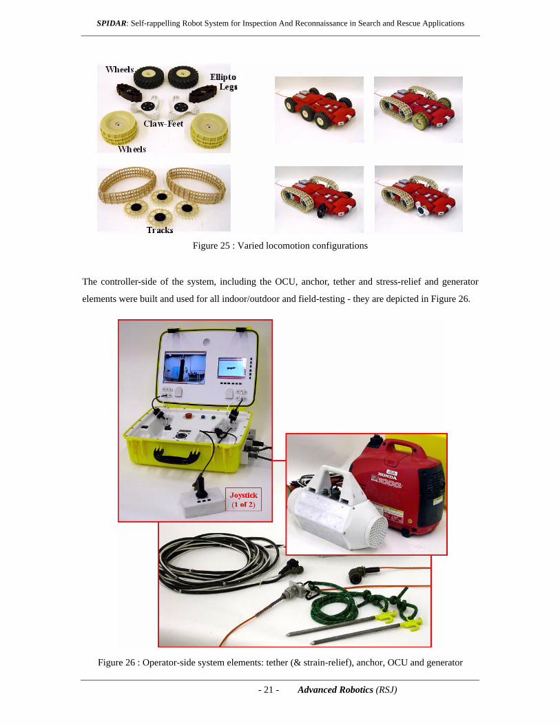
The design capability to adapt different locomotors to the drive-shafts of the vehicle was also
implemented and tested. the different configurations for wheeled, half-track (rear-track with front
wheels) as well as elliptical and club-feet frontal climbing ‘legs’ was evaluated. Functionally the system
was well suited to the concept of locomotor modularity, with interesting test results and counterintuitive
conclusions drawn from field-test evaluations of these configurations - details are provided in the next
section. Figure 25 depicts the different locomotion elements and their differing configurations for the
vehicle platform.
- 21 - Advanced Robotics (RSJ)
SPIDAR: Self-rappelling Robot System for Inspection And Reconnaissance in Search and Rescue Applications
Figure 25 : Varied locomotion configurations
The controller-side of the system, including the OCU, anchor, tether and stress-relief and generator
elements were built and used for all indoor/outdoor and field-testing - they are depicted in Figure 26.
Figure 26 : Operator-side system elements: tether (& strain-relief), anchor, OCU and generator

- 22 - Advanced Robotics (RSJ)
SPIDAR: Self-rappelling Robot System for Inspection And Reconnaissance in Search and Rescue Applications
5. FIELD EXPERIMENTATIONThe testing and evaluation of the system was carried out in the laboratory (functional) as well as at a
disaster-team training facility’s training rubble-pile. Both of these test-activities are reported on below
in a combined fashion, in a more mostly qualitative fashion.
Deployment Site & Configuration
Testing was carried out at the Allegheny Fire and Disaster Response training Facility near Pittsburgh
(see Figure 27). The testing was carried out using a single ‘S&R operator’ carrying the complete load
from a staging site to a presumed disaster site, in order to simulate the complete operational scenario (see
Figure 27).
Figure 27 : Field-trial deployment site and single-operator load-out configuration
Field-Testing
During field-testing the system proved its capabilities (see Figure 28) and showed the value of chassis-
articulation, rappelling, multi-sensor telepresence and simplicity of OCU use and unlimited endurance.
Figure 28 : System experimentation scenarios
- 23 - Advanced Robotics (RSJ)
SPIDAR: Self-rappelling Robot System for Inspection And Reconnaissance in Search and Rescue Applications
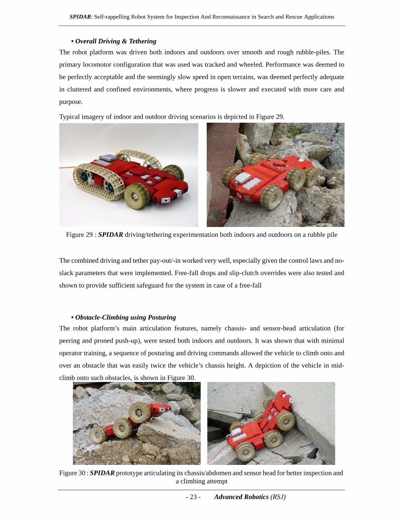
• Overall Driving & TetheringThe robot platform was driven both indoors and outdoors over smooth and rough rubble-piles. The
primary locomotor configuration that was used was tracked and wheeled. Performance was deemed to
be perfectly acceptable and the seemingly slow speed in open terrains, was deemed perfectly adequate
in cluttered and confined environments, where progress is slower and executed with more care and
purpose.
Typical imagery of indoor and outdoor driving scenarios is depicted in Figure 29.
Figure 29 : SPIDAR driving/tethering experimentation both indoors and outdoors on a rubble pile
The combined driving and tether pay-out/-in worked very well, especially given the control laws and no-
slack parameters that were implemented. Free-fall drops and slip-clutch overrides were also tested and
shown to provide sufficient safeguard for the system in case of a free-fall
• Obstacle-Climbing using PosturingThe robot platform’s main articulation features, namely chassis- and sensor-head articulation (for
peering and proned push-up), were tested both indoors and outdoors. It was shown that with minimal
operator training, a sequence of posturing and driving commands allowed the vehicle to climb onto and
over an obstacle that was easily twice the vehicle’s chassis height. A depiction of the vehicle in mid-
climb onto such obstacles, is shown in Figure 30.
Figure 30 : SPIDAR prototype articulating its chassis/abdomen and sensor head for better inspection and a climbing attempt

- 24 - Advanced Robotics (RSJ)
SPIDAR: Self-rappelling Robot System for Inspection And Reconnaissance in Search and Rescue Applications
• Locomotor PerformanceAnother one of the features that was tested, was the ability of the platform to accept different locomotor
options, as depicted earlier in Figure 25. Based on early experimentation, it was determined that neither
the claw-feet nor ellipto-legs offered any substantial improvement over a coarse-treaded tire in the front.
This is most likely due to the equivalent diameter of these to the wheel and the fact that the rubble pile
used for testing was not excessively jagged with relatively even-sized rubble-sections. Furthermore,
especially during multi-turn motions on rubble with jagged edges, the tread was found to many times
jam and tend to de-tread, leading us to abandon the hybrid tracked configurations from further
evaluation. We limited further testing simply to the all-wheel platform (see Figure 31) for consistent data
results and evaluation.
Figure 31 : Multiple locomotor configurations tested; wheeled locomotor deemed most reliable
• Articulation for InspectionThe articulation of the chassis also allows the tilt-camera and sensor-head to reach spaces, whether
above the vehicle or below it (see Figure 32), to perform a more close-up inspection. This is especially
valuable for areas that the vehicle will not be able to reach, which will inevitably happen.
Figure 32 : SPIDAR prototype articulating its chassis/abdomen, sensor head and tilt-camera for (i) better up-above inspection views, and (ii) to perform a crevasse inspection
- 25 - Advanced Robotics (RSJ)
SPIDAR: Self-rappelling Robot System for Inspection And Reconnaissance in Search and Rescue Applications
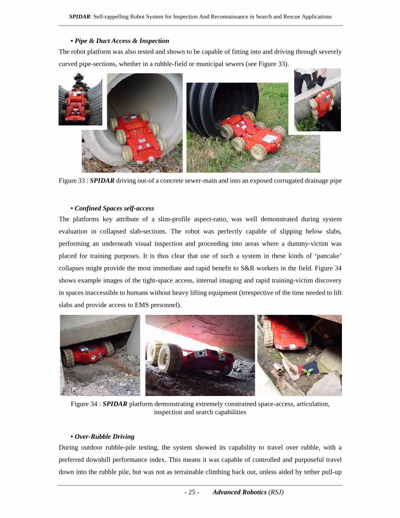
• Pipe & Duct Access & InspectionThe robot platform was also tested and shown to be capable of fitting into and driving through severely
curved pipe-sections, whether in a rubble-field or municipal sewers (see Figure 33).
Figure 33 : SPIDAR driving out-of a concrete sewer-main and into an exposed corrugated drainage pipe
• Confined Spaces self-accessThe platforms key attribute of a slim-profile aspect-ratio, was well demonstrated during system
evaluation in collapsed slab-sections. The robot was perfectly capable of slipping below slabs,
performing an underneath visual inspection and proceeding into areas where a dummy-victim was
placed for training purposes. It is thus clear that use of such a system in these kinds of ‘pancake’
collapses might provide the most immediate and rapid benefit to S&R workers in the field. Figure 34
shows example images of the tight-space access, internal imaging and rapid training-victim discovery
in spaces inaccessible to humans without heavy lifting equipment (irrespective of the time needed to lift
slabs and provide access to EMS personnel).
Figure 34 : SPIDAR platform demonstrating extremely constrained space-access, articulation, inspection and search capabilities
• Over-Rubble DrivingDuring outdoor rubble-pile testing, the system showed its capability to travel over rubble, with a
preferred downhill performance index. This means it was capable of controlled and purposeful travel
down into the rubble pile, but was not as terrainable climbing back out, unless aided by tether pull-up
- 26 - Advanced Robotics (RSJ)
SPIDAR: Self-rappelling Robot System for Inspection And Reconnaissance in Search and Rescue Applications
(in reverse) - a not-so-surprising finding. We believe this to also be insensitive to the kinds of locomotors
(types and sizes) that were prototyped for evaluation purposes. Chassis/Body articulation was shown to
ease and overcome hang-ups and high-centering. Scenarios that were tested are depicted in Figure 30.
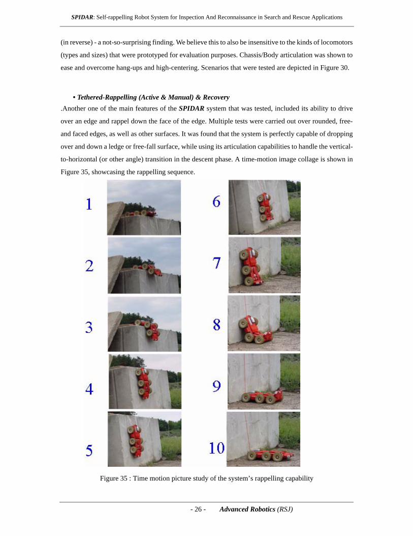
• Tethered-Rappelling (Active & Manual) & Recovery.Another one of the main features of the SPIDAR system that was tested, included its ability to drive
over an edge and rappel down the face of the edge. Multiple tests were carried out over rounded, free-
and faced edges, as well as other surfaces. It was found that the system is perfectly capable of dropping
over and down a ledge or free-fall surface, while using its articulation capabilities to handle the vertical-
to-horizontal (or other angle) transition in the descent phase. A time-motion image collage is shown in
Figure 35, showcasing the rappelling sequence.
Figure 35 : Time motion picture study of the system’s rappelling capability

- 27 - Advanced Robotics (RSJ)
SPIDAR: Self-rappelling Robot System for Inspection And Reconnaissance in Search and Rescue Applications
The system was also capable of pulling itself up a sharp-ledged edge, allowing for the full weight of the
robot to be carried by the tether and the TMS. We did however only succeed in overcoming the edge of
the precipice (in reverse), if the edge was not sharp, but rather curved. The reason for this was the fact
that the rear wheels tended to become excessively compressed and not provide a ledge-climb bite on the
edge when reversing. A possible solution would be to actually place the leg/claw-feet locomotors on the
rear axle for those types of motions, but with an increased leg-length (effective diameter), so they stick
out beyond the rear edge of the chassis. This test clearly showed the value and capability of the system
in being able to rappel, yet also illustrated the need for additional testing and locomotor design
improvement to successfully carry out a rappelling motion in reverse.
6. SUMMARY & CONCLUSIONSThe testing and evaluation of the system was carried out in the laboratory (functional) as well as at a
disaster-team training facility’s training rubble-pile. The system proved its capabilities and showed the
value of chassis-articulation, rappelling, multi-sensor telepresence and simplicity of OCU use and
unlimited endurance. Wheeled locomotors were found to be the all-around optimal configuration while
sharp-edge backwards rappelling was a substantial challenge. Overall the system performed very well,
accessing tight areas and capable of finding (simulated) trapped victims purely by teleoperation and
without prior knowledge of the environment. The experimental effort and the conclusions drawn from
those results, can best be summarized in bulleted form below:
• Overall Concept & System Design- Tethered rappelling capability designed into the robot adds great capability for
S&R applications, due to the severe terrain such as collapsed urban structures after a natural or man-made disaster. On-board tether-spooling was shown to work very well, and allows for more freedom and dramatic maneuvers regardless of terrain type and distance.
- The controller developed for SPIDAR’s TMS clearly proved itself to provide the right and proper operational behaviors during spooling on/off, whether under tension or not and even its safety-features for free-fall protection.
- The articulating chassis proved to be key to terrainability and inspection-access, due to its ability to perch, inch-along (like a seal) and actively change the geometry and thus the CG-location and effects.
- Flexible locomotor running-gear configurations are still believed to be valuable once improved locomotors are developed and tested.
• System Performance- Downward/Upward rappelling was shown to work and be robust over and down
a sharp ledge and making the transition back on to flat floors, while also being able to rappel back up the same ledge. What the system was not able to do, is rappel backwards over a sharp (especially overhanging) edge (see Recommendations section), while smoother ledges were not a problem.
- Multi-camera viewing key was deemed key for telepresent operations in unstructured environments. Individual camera-switching or multi-camera
- 28 - Advanced Robotics (RSJ)
SPIDAR: Self-rappelling Robot System for Inspection And Reconnaissance in Search and Rescue Applications
single-view digitally-stitched imagery, was deemed to be key to generate a sense of the environment with the operator. Single-camera or front/rear camera solutions are not necessarily sufficient in very cluttered and unstructured environments.
- Sensor articulation was extremely useful to provide for easier over-precipice and into-crevasse inspections without requiring much vehicle motions and articulation. This was deemed beneficial when approaching rough terrain and inspecting for potential dangers, human presence or other elements of interest.
- The flexible OCU setup (joysticks, etc.) was very useful in the field, by allowing the operator to remove and use the joystick in an operator-selected ergonomic posture, rather than requiring them to hunch over the suitcase OCU, to reach the joysticks and shield the screen for better viewing.
- The 6x6 AWD wheels-only platform proved itself to be the most versatile and robust in rubble-pile inspections. Tracks were simply too prone to detracking, while the club-feet and ellipto-legs were not size-appropriate and will need another design-iteration and re-testing.
• Value as a S&R and Inspection Platform- The tethered rappelling robot adds great capability to the S&R operator’s toolkit.
These kinds of platforms offer new capabilities over other existing platforms, whether tethered or untethered, for use in extreme rubble-pile terrains when access, speed of response and survivor-searches are the paramount mission parameter and goal.
- Single operator portability is key to user acceptance based on preliminary feedback from first responders. The ability for a single operator to not only operate SPIDAR, but to also deal with all the logistics of transportation and setup of the system, was a key design driver to enhance its utility and acceptance by existing S&R technicians.
- Unlimited endurance due to power-tethering is clearly essential to successful S&R deployments. The goal of tethering a robot to achieve guaranteed communications link and unlimited endurance was also proven out through the design and the experimentation under field-conditions (time, environment, weather, temperature, etc.).
Overall ATK believes that SPIDAR represents a novel and extremely capable and indispensable tool for
S&R teams carrying out their activities in urban settings (post natural/man-made disasters). as well as a
tool for special-purpose missions, whether they be civil-defense or military-mission related.
7. RECOMMENDATIONSBased on the results of the experimental evaluation program, the SPIDAR program has collected a
number of incremental and drastic improvement recommendations for consideration in future
developments of rappelling robots. The items provided below are limited to drastic improvements for
future developments for items that did not perform as well as expected (highlighting the negatives rather
than the positives for the sake of drastic improvements.
Rappelling back over sharp (~65o+) edges will require a more careful consideration of body articulation,
- 29 - Advanced Robotics (RSJ)
SPIDAR: Self-rappelling Robot System for Inspection And Reconnaissance in Search and Rescue Applications
traction and tethering articulation. Challenges to be met are highlighted by the type of wall-crawlers
developed recently [12], where traction and articulation are key to overcoming a sharp edge during an
ascent. Locomotor types require additional research to ensure full advantage is taken to utilize tracks in
rough terrain (without detracking) and claw-feet are better utilized for additional traction and edge-
climbing. Lastly, the advantages of a separately articulating sensor-mast, rather than a sensor-studded
chassis-element would provide additional separation between the locomotion platform and the
telepresence sensing, simplifying the operator’s already complex task load.
Earlier designs and preliminary testing data, as well as a performance video were presented late in 2008
[13], with a detailed set of conclusions and recommendation from this program available as soon as the
submitted final report [14] is publicly released.
8. PROJECT STATUSThe project has completed its Phase II prototype development and testing effort under funding from
DARPA to Automatika, Inc. (ATK), including testing in simulated and training environments in the
summer of 2008. The final prototype is expected to be demonstrated to the sponsors and first responders
in early winter 2008, and undergo additional end-user testing in the USA by the winter of the same year.
ATK expects to improve on the system and offer a commercial SPIDAR version sometime in the second
half of 2009.
9. ACKNOWLEDGMENTSThe authors wish to acknowledge funding support for this effort by the Defense Advanced Research
Projects Agency (DARPA) under SBIR Phase I and II grant No. W31P4Q-06-C-0019 through the US
Department of the Army.
10. REFERENCES[1] Gage, A., Murphy, R., and Minten, B., “Shadowbowl 2003: Lessons Learned from a Reachback
Exercise with Rescue Robots,” IEEE Robotics and Automation Magazine[2] Murphy, R.R., “Rescue Robots at the World Trade Center from Sept. 11-21, 2001“, IEEE Robotics
and Automation Magazine.[3] R. Hogg, NASA Jet Propulsion Laboratory, Micro-Robot Explorer.[4] Murphy, R., “Rescue Robotics for Homeland Security,” Communications of the ACM, special issue
on Homeland Security, vol. 27, no. 3, March 2004, pp. 66-69.[5] Schempf, H. et al, “Less is More: AURORA - an example of minimalistic design for tracked loco-
motion”, ISSR 2001, Lorne, Australia, November 2001[6] Murphy, R.R., “NSF Summer Field Institute for Rescue Robots for Research and Response (R4),”
AI Magazine, Vol. 25, No. 1, Spring 2004.

- 30 - Advanced Robotics (RSJ)
SPIDAR: Self-rappelling Robot System for Inspection And Reconnaissance in Search and Rescue Applications
[7] P. Pirjanian, C. Leger, E. Mumm, B. Kennedy, M. Garrett, H. Aghazarian, S. Farritor, and P. Schen-ker, “Distributed Control for a Modular, Reconfigurable Cliff Robot,” Proceedings of the 2002IEEE, International Conference on Robotics & Automation (ICRA), Washington, DC, May 2002
[8] Micire, M., “Analysis of the Robotic-Assisted Search and Rescue Response to the World Trade Cen-ter Disaster,” Masters Thesis, University of South Florida, July 2002.
[9] Schempf, H. et al, “Evolution of Urban Robotic Systems Developments”, IEEE/ASME Int. Confer-ence on Advanced Intelligent Mechatronics, September 19-22, Atlanta, GA, 1999
[10] D. Apostolopoulos and J. Bares, “Locomotion configuration of a robust rappelling robot,” Pro-ceedings of the 1995 IEEE/RSJ International Conference on Intelligent Robots and Systems,Human Robot Interaction and Cooperative Robots (IROS '95), Vol. 3, August, 1995, pp. 280 - 284
[11] Franz Hover, Mark Grosenbaugh and Michael Triantafyllou, “Calculation of Dynamic Tensionsand Motions of Towed Underwater Vehicles”, IEEE, Journal of Oceanic Engineering, 1994.
[12] http://www.bostondynamics.com/content/sec.php?section=RiSE[13] Schempf, H. et al, “SPIDAR: SPinneret for Inspection and Reconnaissance in Search and Rescue
Applications”, 2008 IEEE Int. Workshop on Safety, Security and Rescue Robotics, Sendai, Japan,October 21-24, 2008
[14] Schempf, H. et al, “SPIDAR: A SPinneret tethered rappelling search-and-rescue robot for extremeenvironments”, SBIR II Final Report to DARPA
[15] Jacoff, A., Weiss, B., Messina, E., Evolution of a Performance Metric for Urban Search and RescueRobots (2003), Proceedings of the 2003 Performance Metrics for Intelligent Systems (PerMIS)Workshop, Gaithersburg, MD, September 16 - 18, 2003
Recommended