SECTION 5 - ELECTRICAL
Description Rev. # Pg. #
Pivot Panel - 2-76 to 3-79 .................................................................................................. 4-91 5-1Inner Panel Components .................................................................................................. 2-03 5-211-Wire Control Panel ....................................................................................................... 3-03 5-3 Pivot Panel Main Disconnect Switch Kit ......................................................................... 3-03 5-3.1 Standard Pivot Box 11 Wire Pivot Panel CSA ................................................................. 2-03 5-3.2 Standard Pivot Box 11 Wire Pivot Panel CSA Parts List ................................................ 8-05 5-3.3 Standard Pivot Box 11 Wire Pivot Panel CSA ................................................................. 2-03 5-3.4Standard Pivot Box 11 Wire Pivot Panel CSA Parts List ................................................ 3-03 5-3.5 Standard Pivot Box 6000 ................................................................................................... 2-03 5-3.6 Standard Pivot Box 6000 Parts List ................................................................................. 3-03 5-3.7 Standard Pivot Box 6000 CSA .......................................................................................... 2-03 5-3.8 Standard Pivot Box 6000 CSA Parts List ......................................................................... 3-03 5-3.9 Standard Pivot Panel 6000 C:A:M:S ................................................................................. 3-03 5-3.10Standard Pivot Panel 6000 C:A:M:S 45 Amp ................................................................... 3-03 5-3.11Repair Parts C:A:M:S ...................................................................................................... 10-01 5-3.12 Inner Panel w/1-Piece PCB ............................................................................................... 4-91 5-4 Inner Panel w/Modular PCB’s ........................................................................................... 2-03 5-5 One-Piece PCB .................................................................................................................. 2-03 5-6 Modular 3-Piece PCB ........................................................................................................ 9-05 5-7 Low Pressure Switch ........................................................................................................ 2-03 5-8 9 Conductor Collector Ring .............................................................................................. 8-00 5-9 11, 12 & 14 Conductor Collector Ring - Aero-Motive ..................................................... 8-00 5-10 11 Conductor Collector Ring - Ind. Reel .......................................................................... 8-00 5-11 11 Conductor Collector Ring - Ind. Reel .......................................................................... 8-00 5-12 End Gun Control Switch Box ............................................................................................ 8-04 5-13 Maxi Gun Control Box ....................................................................................................... 8-04 5-14 End-of-Field Stop/Auto Reverse Assy. ............................................................................ 7-93 5-15 Long E-Z Tow E.G.S.O. Auto Rev. & S.I.S. Controls ........................................................ 1-88 5-15.1 End-of-Field Stop/Auto Reverse ....................................................................................... 5-89 5-15.2 End-of-Field Stop/Auto Reverse ....................................................................................... 6-96 5-15.3 End-of-Field Stop/Auto Reverse ....................................................................................... 5-89 5-15.4 End-of-Field Stop/Auto Reverse ....................................................................................... 5-89 5-15.5 Auto Rev./Auto Stop Box Parts List ................................................................................. 4-91 5-15.6 End of Field Stop Box ....................................................................................................... 2-03 5-15.7 End-of-Field Stop Tower Box ............................................................................................ 2-03 5-16 First Tower Box .................................................................................................................. 4-91 5-17 Intermediate Tower Box ..................................................................................................... 1-05 5-18 Intermediate Bolt-On Box ................................................................................................. 1-05 5-19 Time Delay Watering Box .................................................................................................. 3-10 5-20 Switch & Arm Assy. ........................................................................................................... 1-10 5-21 Double Run Tower Box ...................................................................................................... 1-05 5-22 Long Center Pivot Alignment Hdwr.................................................................................. 1-88 5-23 Long Center Pivot Alignment Adjustment ...................................................................... 8-99 5-24 Long Center Pivot Alignment Cable & Hdwr. .................................................................. 6-96 5-25 Long Center Pivot Alignment Pkgs. ................................................................................. 6-96 5-26 Model 6000 Modified Alignment ..................................................................................... 12-98 5-26.1 Model 6000 Modified Alignment - Parts List ................................................................... 8-99 5-26.2 Last Tower Box ................................................................................................................... 4-91 5-27 Last Tower Box - Bolt-On .................................................................................................. 1-05 5-28 Sensor Bearing Support Bracket ..................................................................................... 4-91 5-29 Last Tower Box w/Motorized End Gun ............................................................................. 1-88 5-30
6P50008803-10
Last Tower Box w/Booster Pump ..................................................................................... 6-96 5-31 Booster Pump Box Mod. for Corner................................................................................. 4-92 5-32 Booster Pump Box - Standard System ............................................................................ 3-09 5-33 Intermediate Corner Watering Last Tower Box ............................................................... 3-03 5-33.1Starters ............................................................................................................................... 7-93 5-34 Motor Starters .................................................................................................................... 3-03 5-34.1 2 HP Jacuzzi & Berkeley Booster Pump .......................................................................... 4-92 5-35 2 HP Berkeley Booster Pump ........................................................................................... 7-93 5-36 5 HP Booster Pump ........................................................................................................... 8-05 5-36.1 71/2 HP Berkeley Booster Pump ...................................................................................... 6-96 5-37 Running Light .................................................................................................................... 8-01 5-38Running Light .................................................................................................................... 1-88 5-38.1Running Light .................................................................................................................... 1-88 5-38.2 Booster Transformer - 45 Amp ......................................................................................... 7-01 5-39 Transformer Control Tower Box ....................................................................................... 1-05 5-40 Motorized Ball Valve .......................................................................................................... 1-88 5-41 Motorized Ball Valve .......................................................................................................... 1-88 5-42 Fuses - Pivot Panel ............................................................................................................ 5-89 5-43 Motorized Ball Valve Plumbing ......................................................................................... 1-88 5-44 Electrical Cable Listing ..................................................................................................... 4-92 5-45Grounding Jumper Wire Installation ................................................................................ 7-01 5-45.1Cord Connectors ............................................................................................................... 4-92 5-46 Cable Clamps ..................................................................................................................... 5-06 5-47 Ground Rod ........................................................................................................................ 4-00 5-48 Lima-Winco Generators .................................................................................................... 6-96 5-49 Generator Shield ................................................................................................................ 6-96 5-50 Corner System Pivot Panel w/Mod. PCB ......................................................................... 2-03 5-51 Corner System Pivot Panel w/Mod. PCB ......................................................................... 3-03 5-52 Corner System Pivot Panel 6000 ...................................................................................... 2-03 5-52.1 Corner System Pivot Panel 6000 Parts List .................................................................... 3-03 5-52.2 Corner System Pivot Panel w/1-Piece PCB ..................................................................... 1-88 5-53 Corner System Pivot Panel w/1-Piece PCB ..................................................................... 8-05 5-54 Corner System 9-Wire Pivot Panel ................................................................................... 2-03 5-55 Corner System 9-Wire Pivot Panel ................................................................................... 3-03 5-56 Run Cycle Box ................................................................................................................. 10-96 5-57Run Cycle Box Parts List .................................................................................................. 3-03 5-57.1 Solenoid Valve Box - Prior to 8/84 .................................................................................. 10-06 5-58 Solenoid Valve Box - Eff. 8/84 ......................................................................................... 10-06 5-59 Solenoid Box ...................................................................................................................... 1-88 5-60 Solenoid Box ...................................................................................................................... 4-92 5-61 Internal Chain Sequencing Box ....................................................................................... 4-92 5-61.1 Parts List ............................................................................................................................ 4-92 5-61.2 Solenoid Valve Box ............................................................................................................ 8-98 5-62 Guidance Controls ............................................................................................................ 8-98 5-63 Swing Tower Box w/Single Recvr. .................................................................................... 6-03 5-64 Swing Tower Box w/Single Recvr. (Effective Aug. ’91) ................................................... 6-03 5-64.1Swing Tower Box Reversing Contactors ......................................................................... 6-03 5-64.2Swing Tower Box w/Back-up Recvr. ................................................................................. 5-89 5-65 Swing Tower Box w/Back-up Recvr. ................................................................................. 4-91 5-66 Swing Tower Box Prior to 3-79 ......................................................................................... 4-92 5-67 Swing Tower Box Prior to 3-79 ......................................................................................... 4-92 5-68 Booster Pump Box - Corner - Prior to 3-82 ..................................................................... 4-91 5-69 Booster Pump Box - Corner - After 3-82 ......................................................................... 7-01 5-70Corner - Buried Wire .......................................................................................................... 1-03 5-71 Spinner Tower Box ............................................................................................................. 7-93 5-72 Spinner E-Z Tow Controls ................................................................................................. 1-88 5-73 Spinner Percentage Timer ................................................................................................ 1-88 5-74 Spinner Percentage Timer ................................................................................................ 5-89 5-75

Spinner Overwatering Device ........................................................................................... 1-88 5-76 Percentage Timer & Overwatering Device Mounting Hdwr. ........................................... 1-88 5-77 Multi Tower Slurry First Twr. Box ...................................................................................... 4-92 5-78 Multi Tower Slurry Intermediate Tower Box ..................................................................... 1-88 5-79 Multi Tower Slurry Last Twr. Box ...................................................................................... 4-91 5-80

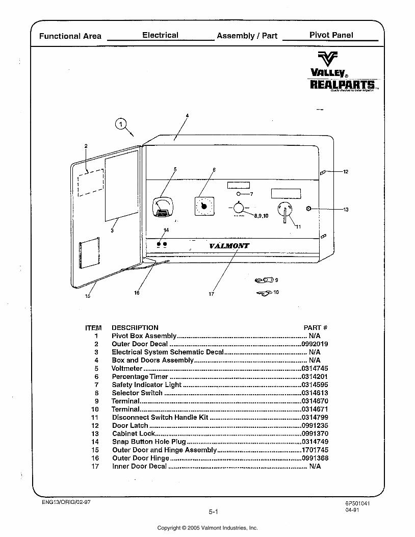
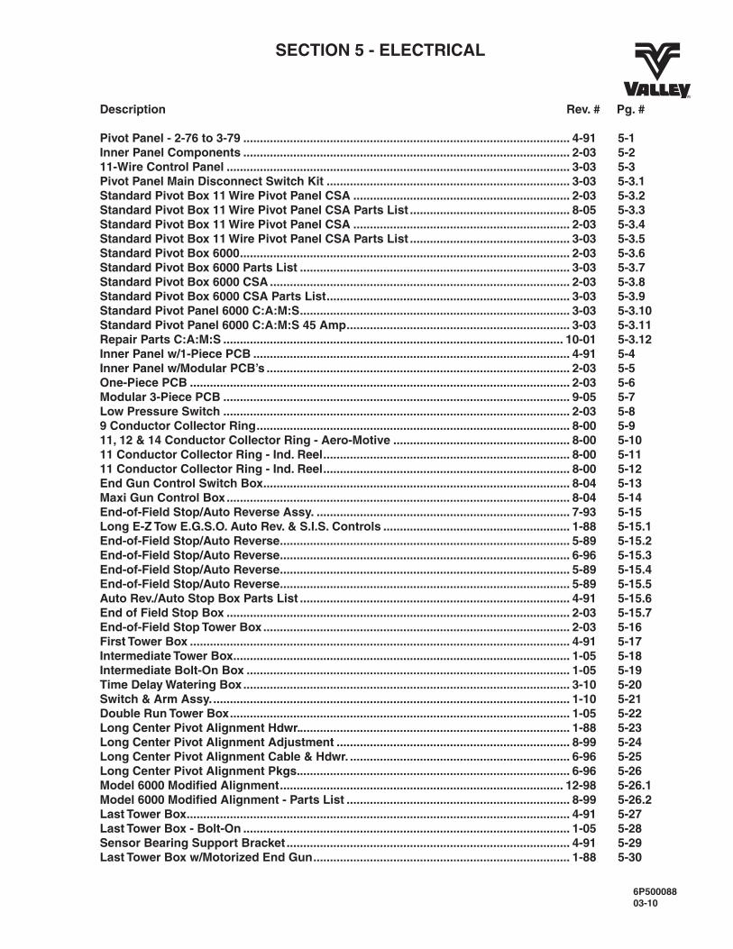
Functional Area Electrical Assembly / Part Pivot Panel
ITEM 1 2 3 4 5 6 7 8 9 10 11 12 13 14 15 16 17
DESCRIPTION PART # Pivot Box Assembly ................................................................ NIA Outer Door Decal ...................................................................... 099201 9 Electrical System Schematic Decal ......................................... NIA Box and Doors Assembly ......................................................... NIA
.................................................................................... Voltmeter 0314745 Percentage Timer .................................................................. 0314201 Safety Indicator Light ............................................................... 0314595 Selector Switch ......................................................................... 031 461 3 Terminal .................................................................................... 0314670 Terminal ...................................................................................... 0314671 Disconnect Switch Handle Kit ............................................... 0314799 Door Latch ............................................................................ 0991 235 Cabinet Lock ............................................................................ 0991 370 Snap Button Hole Plug ............................................................. 0314749 Outer Door and Hinge Assembly ............................................. 1701745 Outer Door Hinge ..................................................................... 0991 368 Inner Door Decal .......................................................................... NIA
Copyright © 2005 Valmont Industries, Inc.
r
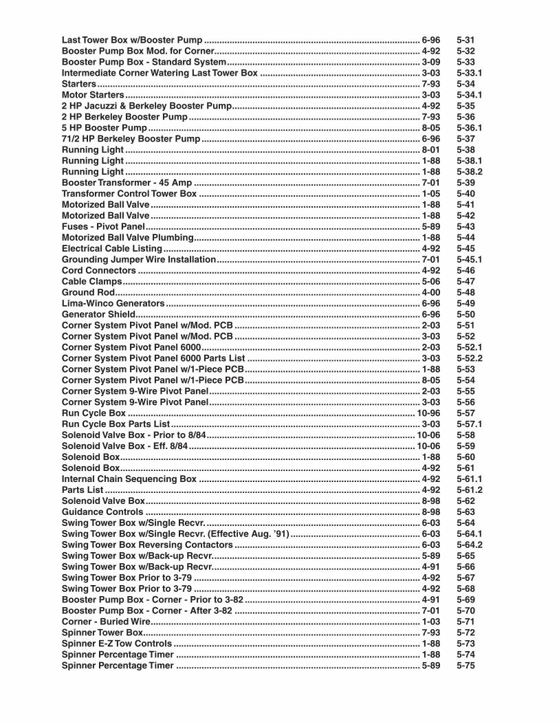
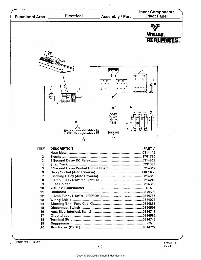
Inner Components ' Functional Area Electrical Assembly / Part Pivot Panel
ITEM 1 2 3 4 5 6 7 8 9
10 11 12 13 14 15 16 17 18 19 20
DESCRIPTION PART # Hour Meter .......................................................................... 0314442
....................................................................................... Bracket 1701785 ......................................................... 3 Second Delay DC Relay 0314813
Snap Track ................................................................................. 0991587 .................................... 3 Second Delay Printed Circuit Board 0314812
Relay Socket (Auto Reverse) .................................................. 03E1650 Latching Relay (Auto Reverse) ................................................ 0314815 5 Amp Fuse (1-112" x 13/32" Dia.) ............................................ 0314243 Fuse Holder ........................................................................... 0314612 480 - 120 Transformer .................................................................. N/A Contactor ................................................................................... 031 4598
............................................ 3 Amp Fuse (1 -112" x 13/32" Dia.) 031 4755 ............................................................................. Wiring Shield 0314978 - .................................................. Shorting Bar Fuse Clip Kit 0314885
.................................................................... Disconnect Switch 0314597 ....................................................... Aux. Elec. Interlock Switch 0314747
Ground Lug .............................................................................. 0314682 Terminal Strip ......................................................................... 031 4746 Suppressor .................................................................................. N/A Run Relay (DPDT) .................................................................... 0314727
Copyright © 2005 Valmont Industries, Inc.
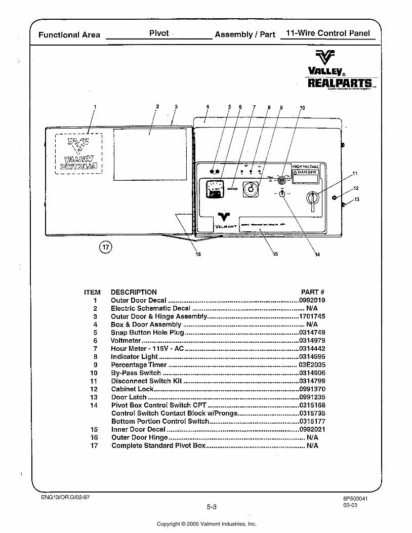
Functional Area Pivot Assembly / part 1 1 -Wire Control Panel
ITEM 1 2 3 4 5 6 7 8 9 10 11 12 13 14
DESCRIPTION PART # ...................................................................... Outer Door Decal 099201 9
Electric Schematic Decal .......................................................... NIA ................................................. Outer Door & Hinge Assembly 1701 745
Box & Door Assembly ............................................................... NIA ............................................................. Snap Button Hole Plug 0314749
.................................................................................... Voltmeter 031 4979 Hour Meter . 11 5V . AC ............................................................. 0314442
........................................................................... Indicator Light 031 4595 Percentage Timer ................................................................... 03E2035 By-Pass Switch .................................................................. 031 4906
.............................................................. Disconnect Switch Kit 0314799 Cabinet Lock .............................................................................. 0991 370 Door Latch ................................................................................. 0991 235 Pivot Box Control Switch CPT ............................................... 031 51 68
................................. Control Switch Contact Block wlProngs 0315735 Bottom Portion Control Switch ................................................ 031 51 77 Inner Door Decal ....................................................................... 0992021 Outer Door Hinge .................................................................... NIA Complete Standard Pivot Box .................................................... NIA
Copyright © 2005 Valmont Industries, Inc.
C
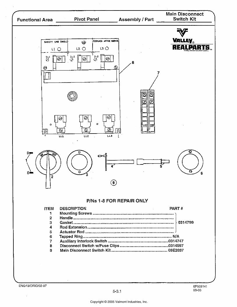
Main Disconnect Functional Area Pivot Panel Assembly / Part Switch Kit
ITEM 1 2 3 4 5 6 7 8 9
PINS 1-8 FOR REPAIR ONLY
DESCRIPTION PART # ........................................................................... Mounting Screws
............................................................................................. Handle Gasket ......................................................................................... 031 4799
................................................................................ Rod Extension Actuator Rod .................................................................................. 1 Tapped Ring ............................................................................ NIA
........................................................ Auxiliary Interlock Switch 0314747 Disconnect Switch wlfuse Clips ............................................. 0314597 Main Disconnect Switch Kit .................................................. 03E2037
Copyright © 2005 Valmont Industries, Inc.
Functional Area ElectricalICSA
Copyright © 2005 Valmont Industries, Inc.
6P50336608-055-3.3
Quality checked for better irrigation
Assembly / PartElectrical/CSAFunctional Area
ENG13/ORIG/02-97
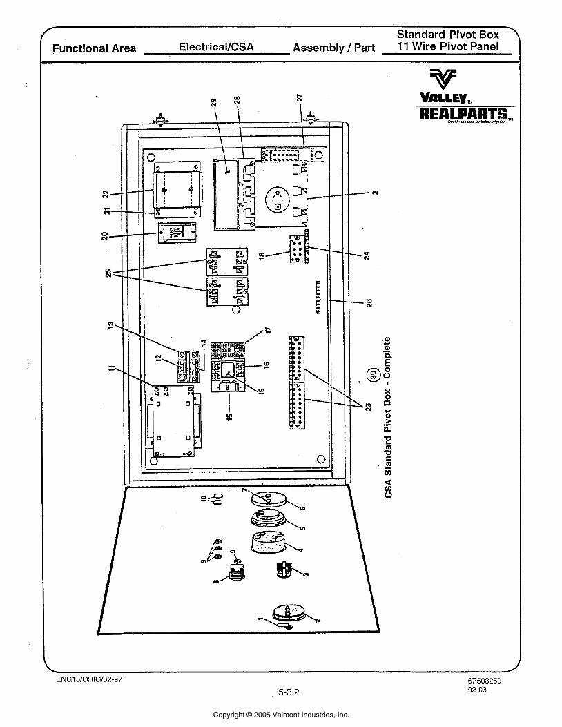
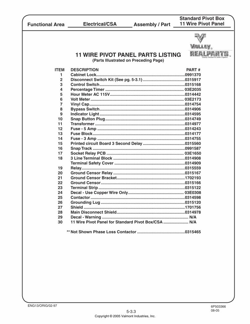
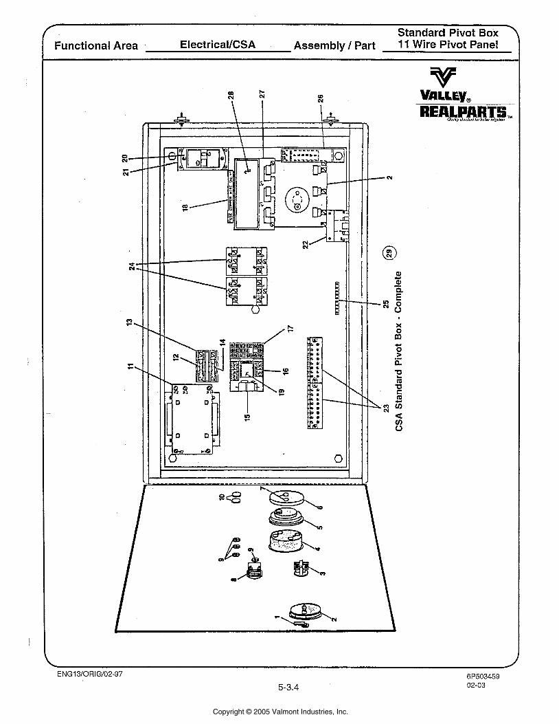
ITEM DESCRIPTION PART # 1 Cabinet Lock ..............................................................................0991370 2 Disconnect Switch Kit (See pg. 5-3.1) .....................................0315917 3 Control Switch ...........................................................................0315168 4 Percentage Timer ..................................................................... 03E2035 5 Hour Meter AC 115V ..................................................................0314442 6 Volt Meter .................................................................................. 03E2173 7 Vinyl Cap ....................................................................................0314754 8 Bypass Switch ...........................................................................0314906 9 Indicator Light ...........................................................................0314595 10 Snap Button Plug ......................................................................0314749 11 Transformer ...............................................................................0314977 12 Fuse - 5 Amp .............................................................................0314243 13 Fuse Block .................................................................................0314177 14 Fuse - 3 Amp .............................................................................0314755 15 Printed circuit Board 3 Second Delay .....................................0315560 16 Snap Track .................................................................................0991587 17 Socket Relay PCB .................................................................... 03E1650 18 3 Line Terminal Block ...............................................................0314908 Terminal Safety Cover ..............................................................0314909 19 Relay ...........................................................................................0315559 20 Ground Censor Relay ...............................................................0315167 21 Ground Censor Bracket ............................................................1702193 22 Ground Censor ..........................................................................0315166 23 Terminal Strip ............................................................................0315122 24 Decal - Use Copper Wire Only ................................................. 03E0308 25 Contactor ...................................................................................0314598 26 Grounding Lug ..........................................................................0315120 27 Shield .........................................................................................1701756 28 Main Disconnect Shield ............................................................0314978 29 Decal - Warning ............................................................................ N/A 30 11 Wire Pivot Panel for Standard Pivot Box/CSA ...................... N/A
** Not Shown Phase Loss Contactor ..........................................0315465
Standard Pivot Box11 Wire Pivot Panel
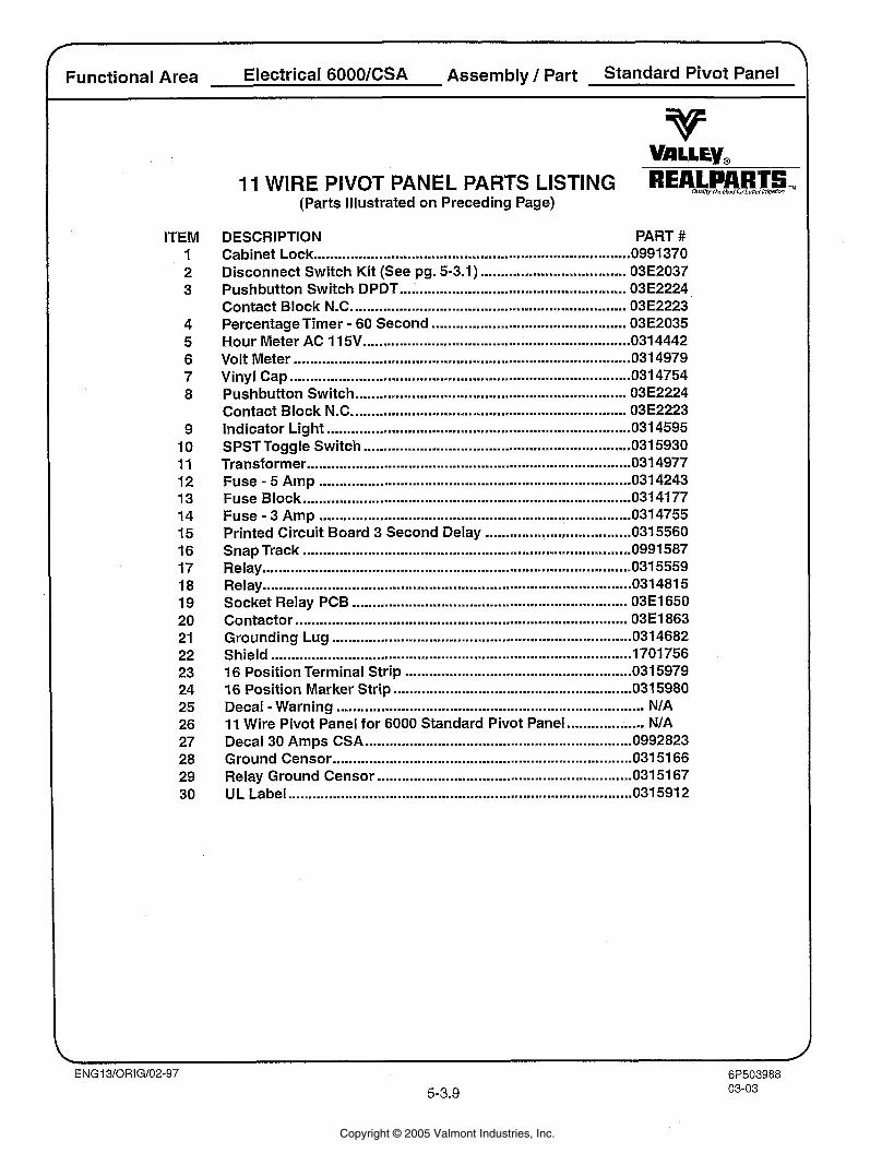
11 WIRE PIVOT PANEL PARTS LISTING(Parts Illustrated on Preceding Page)
Copyright © 2005 Valmont Industries, Inc.
f l
Standard Pivot Box Functional Area Electrical/CSA Assembly / Part 11 Wire Pivot Panel
Copyright © 2005 Valmont Industries, Inc.
Standard Pivot Box >
Functional Area ElectricalICSA Assembly / Part 1 1 Wire Pivot Panel
ITEM 1 2 3 4 5 6 7 8 9 10 11 12 13 14 15 16 17 18 19 20 21 22 23 24 25 26 27 28 29
IIWIREPIVOTPANELPARTSL~STING REALPARTS. QuaW c h s s w forben~rinig~~lion
(Parts Illustrated on Preceding Page)
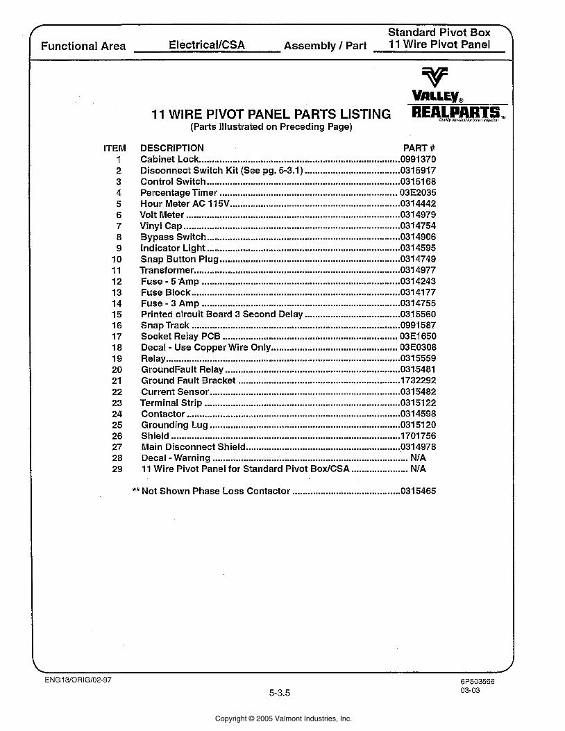
DESCRIPTION PART # Cabinet Lock ........................................................................... 0991 370
..................................... Disconnect Switch Kit (See pg . 5.3.1) 0315917 Control Switch ........................................................................ 031 51 68 Percentage Timer ..................................................................... 03E2035 Hour Meter AC 1 15V ................................................................ 031 4442 Volt Meter ................................................................................... 031 4979 Vinyl Cap .................................................................................... 031 4754 Bypass Switch ......................................................................... 034906
........................................................................... Indicator Light 031 4595 ...................................................................... Snap Button Plug 0314749
................................................................................ Transformer 031 4977 Fuse . 5 Amp ............................................................................. 031 4243 Fuse Block ................................................................................. 031 4177
............................................................................. . Fuse 3 Amp 031 4755 ..................................... Printed circuit Board 3 Second Delay 031 5560
Snap Track ................................................................................ 0991 587 Socket Relay PCB ................................................................... 03E1650 Decal . Use Copper Wire Only ............................................... 03E0308 Relay ...................................................................................... 0 3 1 5559 GroundFault Relay .................................................................... 031 5481 Ground Fault Bracket ............................................................. 1732292 Current Sensor ......................................................................... 031 5482 Terminal Strip ............................................................................ 031 51 22 Contactor ............................................................................. 031 4598 Grounding Lug ..................................................................... 031 5120 Shield ......................................................................................... 1701756 Main Disconnect Shield ........................................................... 031 4978 Decal -Warning ............................................................................ NIA
...................... 11 Wire Pivot Panel for Standard Pivot BoxlCSA NIA
..................... ** Not Shown Phase Loss Contactor .................... 0315465
Copyright © 2005 Valmont Industries, Inc.
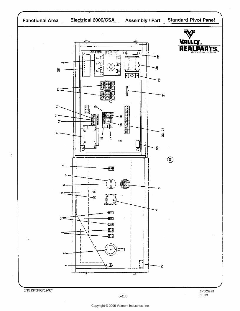
Functional Area Electrical 6000 Assembly / Part Standard Pivot Panel
Copyright © 2005 Valmont Industries, Inc.
Functional Area ElectricaVCSA Assembly / Part Standard Pivot Panel
ITEM 1 2 3
***4
4 5 6 7 8 9
10 11 12 13 14 15 16 17 18 19 20 21 22 23 24 25
. 26 27 28 29
11 WIRE PIVOT PANEL PARTS LISTING REALPART auaeg. chs&~forbanBIirI~aUon TM
(Parts Illustrated on Preceding Page)
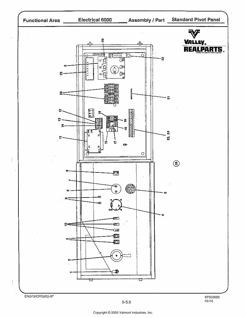
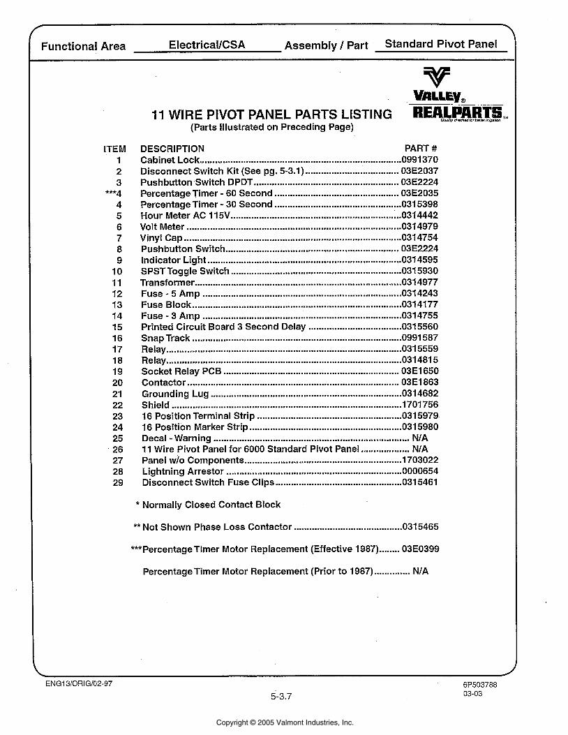
DESCRIPTION PART # Cabinet Lock ........................................................................ 0991 370 Disconnect Switch Kit (See pg . 5.3.1) .................................... 03E2037 Pushbutton Switch DPDT ....................................................... 03E2224 Percentage Timer . 60 Second ............................................. 03E2035 Percentage Timer . 30 Second ................................................ 031 5398 Hour Meter AC 1 15V .............................................................. 031 4442
................................................................................... Volt Meter 031 4979 .................................................................................... Vinyl Cap 031 4754
Pushbutton Switch .............................................................. 03E2224 ........................................................................... Indicator Light 031 4595
SPST Toggle Switch ........................................................... 031 5930 ................................................................................ Transformer 031 4977
Fuse . 5 Amp ............................................................................. 031 4243 Fuse Block ................................................................................ 0314177
............................................................................. . Fuse 3 Amp 031 4755 Printed Circuit Board 3 Second Delay .................................... 0315560 Snap Track ................................................................................. 0991 587 Relay ........................................................................................... 031 5559 Relay .......................................................................................... 031 481 5 Socket Relay PCB .................................................................... 03E1650 Contactor .................................................................................. 03E1863 Grounding Lug ......................................................................... 0314682 Shield ......................................................................................... 1701756
........................................................ 16 Position Terminal Strip 031 5979 16 Position Marker Strip ........................................................... 031 5980 Decal -Warning ............................................................................ NIA 11 Wire Pivot Panel for 6000 Standard Pivot Panel ................... NIA Panel wlo Components ............................................................. 1703022 Lightning Arrestor .................................................................... 0000654 Disconnect Switch Fuse Clips ................................................. 0315461
* Normally Closed Contact Block
** Not Shown Phase Loss Contactor .......................................... 031 5465
***Percentage Timer Motor Replacement (Effective 1987) ........ 03E0399
Percentage Timer Motor Replacement (Prior to 1987) .............. NIA
Copyright © 2005 Valmont Industries, Inc.
Functional Area Electrical 6000lCSA Assembly / Part Standard Pivot Panel
Copyright © 2005 Valmont Industries, Inc.
Functional Area Electrical 6000lCSA Assembly / Part Standard Pivot Panel
ITEM 1 2 3
4 5 6 7 8
9 10 11 12 13 14 15 16 17 18 19 20 21 22 23 24 25 26 27 28 29 30
I I WIRE PIVOT PANEL PARTS LISTING REALPART ouelity chsckadlorbs#nrImgabon
(Parts Illustrated on Preceding Page)
DESCRIPTION PART # Cabinet Lock ............................................................................ 0991370 Disconnect Switch Kit (See pg . 5.3.1) .................................... 03E2037 Pushbutton Switch DPDT ..................................................... 03E2224 Contact Block N.C ................................................................... 03E2223 Percentage Timer . 60 Second ................................................ 03E2035 Hour Meter AC 1 15V ............................................................... 031 4442
................................................................................... Volt Meter 031 4979 .................................................................................... Vinyl Cap 031 4754
Pushbutton Switch ................................................................ 03E2224 ................................................................... Contact Block N.C. 03E2223
........................................................................... Indicator Light 0314595 SPST Toggle Switch ................................................................ 031 5930
................................................................................ Transformer 031 4977 Fuse . 5 Amp ........................................................................ 0314243 Fuse Block ................................................................................. 031 4177 Fuse . 3 Amp ............................................................................. 031 4755 Printed Circuit Board 3 Second Delay .................................... 0315560 Snap Track ............................................................................ 0991587 Relay ........................................................................................ 031 5559 Relay ......................................................................................... 031 481 5 Socket Relay PCB .................................................................. 03E1650 Contactor ............................................................................ 03E1863 Grounding Lug .......................................................................... 0314682
......................................................................................... Shield 1701756 16 Position Terminal Strip ..................................................... 0315979 16 Position Marker Strip .......................................................... 031 5980 Decal -Warning ..................................................................... N/A
................... 11 Wire Pivot Panel for 6000 Standard Pivot Panel N/A Decal 30 Amps CSA .................................................................. 0992823 Ground Censor ...................................................................... 031 51 66 Relay Ground Censor ............................................................... 031 51 67 UL Label .................................................................................... 031 5912
Copyright © 2005 Valmont Industries, Inc.
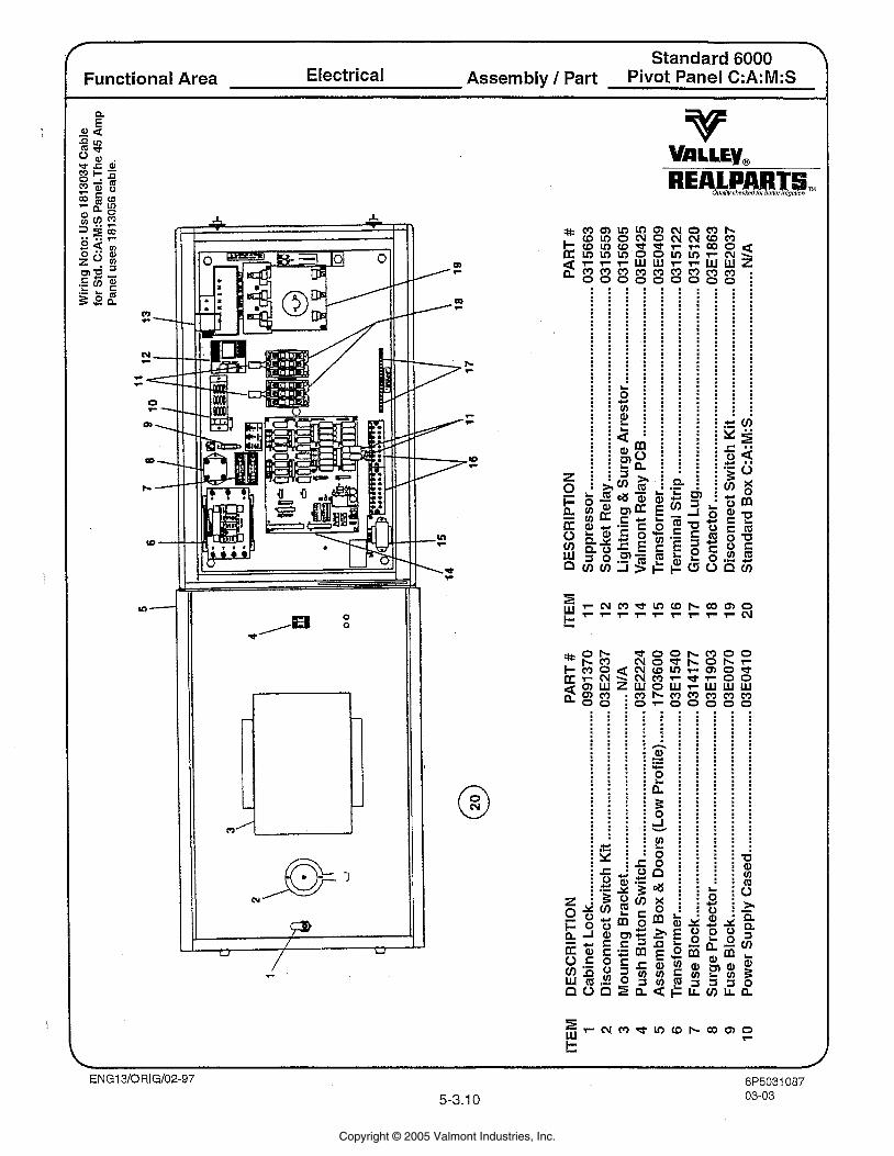
. Standard 6000
Functional Area Electrical Assembly 1 Part Pivot Panel C:A:M:S
lo-
w-
Copyright © 2005 Valmont Industries, Inc.
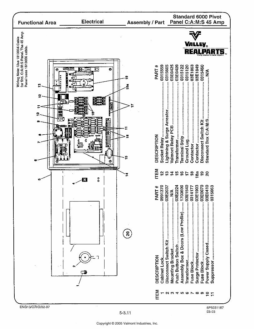
Standard 6000 Pivot '
Functional Area Electrical Assembly 1 Part Panel C:A:M:S 45 Amp
Copyright © 2005 Valmont Industries, Inc.
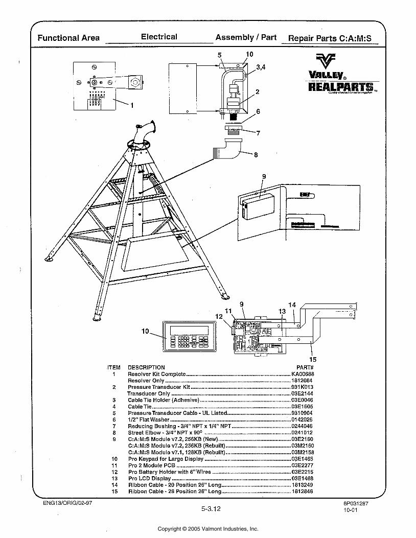
Functional Area Electrical Assembly 1 Part Repair Parts C:A:M:S
15 DESCRIPTION PART# Resolver Kit Complete ..................................................................... KA00688 Resolver Only .................................................................................. 181 2084 Pressure Transducer Kit .................................................................. 931 KO1 3 Transducer Only ........................................................... ................... 03E2144 Cable Tie Holder (Adhesive) ............................................................ 03E0046 Cable Tie ............................................................................................ 03E1605
. .......................................... Pressure Transducer Cable UL Listed 931 0904 112" Flat Washer ................................................................................ 01 42026 Reducing Bushing . 314" NPT x 114" NPT ....................................... 0244046 Street Elbow . 314" NPT x 90° ........................................................ 0241 012 C:A:M:S Module v7.2. 256KB (New) ................................................ 03E2160
........................................... C:A:M:S Module v7.2. 256KB (Rebuilt) 03M2160 C:A:M:S Module v7.1. 128KB (Rebuilt) ........................................... 03M2158 Pro Keypad for Large Display ......................................................... 03E1465 Pro 2 Module PCB ............................................................................ 03E2277
.................................................... Pro Battery Holder with 6"Wires 03E2215 Pro LCD Display ............................................................................... 03E1468 Ribbon Cable . 20 Position 26" Long ............................................. 1813249 Ribbon Cable . 26 Position 26" Long .............................................. 1812846
ITEM 1
2
3 4 5 6 7 8 9
10 11 12 13 14 15
Copyright © 2005 Valmont Industries, Inc.
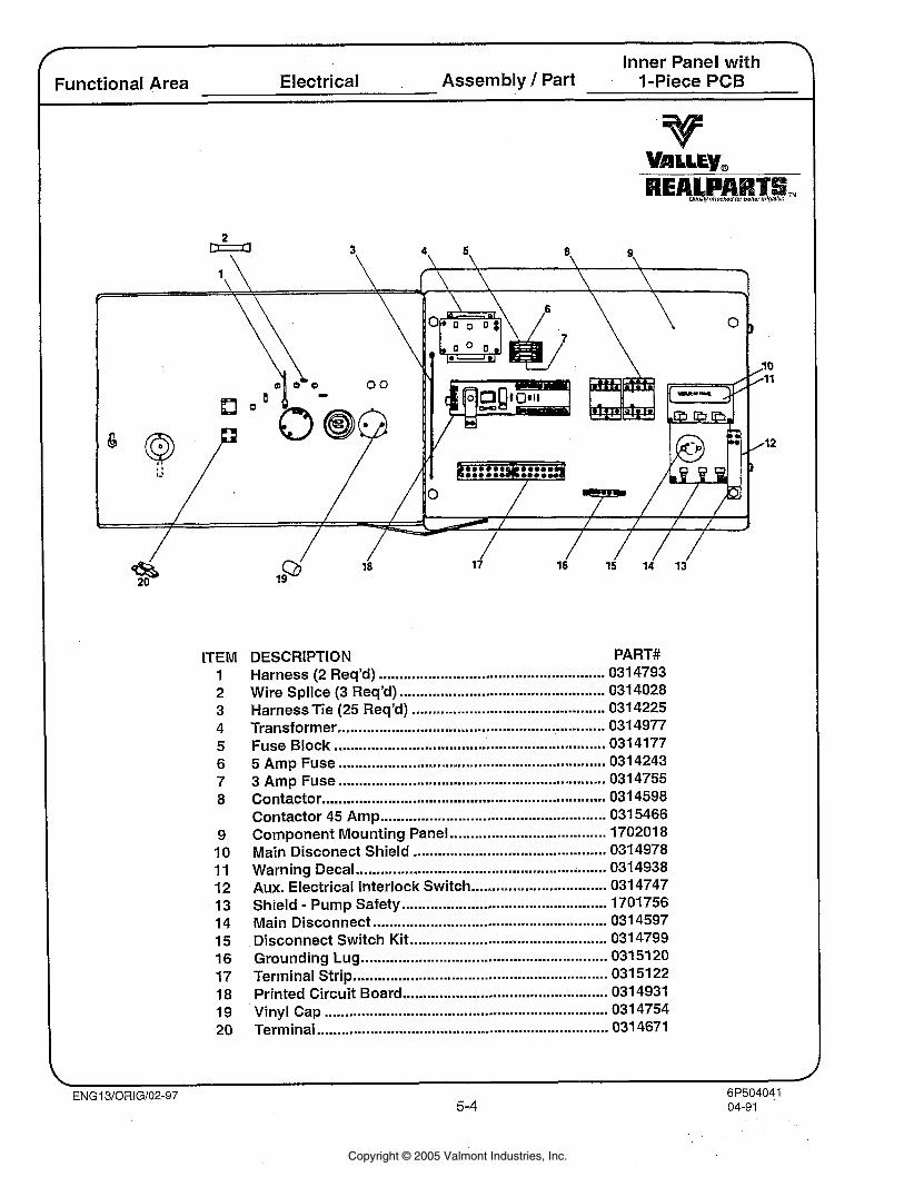
Inner ranel wrtn Functional Area Electrical Assembly 1 Part I-Piece PCB
ITEM 1 2 3 4 5 6 7 8
9 10 11 12 13 14 15 16 17 18 19 20
DESCRIPTION PART# Harness (2 Req'd) ....................................................... 031 4793
.................................................. Wire Splice (3 Req'd) 0314028 Harness Tie (25 Req'd) ............................................... 031 4225 Transformer ............................................................... 031 4977 Fuse Block ............................................................ 0314177
................................................................. 5 Amp Fuse 0314243 3 Amp Fuse .............................................................. 0314755 Contactor ..................................................................... 0314598 Contactor 45 Amp .................................................... 031 5466
...................................... Component Mounting Panel 170201 8 Main Disconect Shield .............................................. 0314978 Warning Decal .......................................................... 0314938 Aux . Electrical Interlock Switch ................................. 0314747 Shield . Pump Safety ............................................. 1701756
......................................................... Main Disconnect 0314597 ................................................ Disconnect Switch Kit 0314799
Grounding Lug .......................................................... 031 51 20 .............. Terminal Strip ... ................................... 031 5122
.................................................. Printed Circuit Board 0314931 ..................................................................... Vinyl Cap 0314754
....................................................................... Terminal 031 4671
Copyright © 2005 Valmont Industries, Inc.
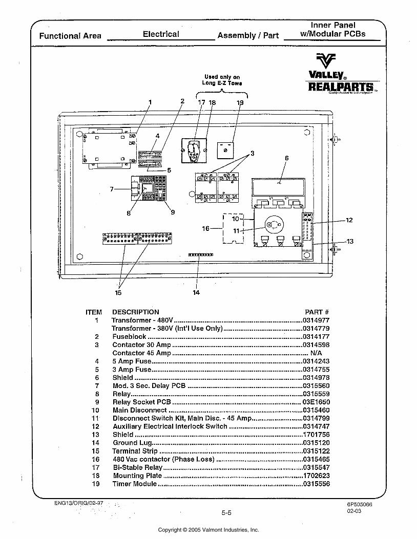
f Inner Panel . Functional Area Electrical Assembly / Part w ~ n k x k h r PCBs
Used only on Long E-Z Tows
ITEM 1
2 3
4 5 6 7 8 9
10 11 12 13 14 15 16 17 18 19
DESCRIPTION PART # Transformer . 480V .................................................................... 031 4977
.......................................... . Transformer 380V (Int'l Use Only) 0314779 Fuseblock .............................................................................. 031 4177 Contactor 30 Amp ..................................................................... 0314598 Contactor 45 Amp ................................................................... NIA 5 Amp Fuse ........................................................................... 0314243 3 Amp Fuse ............................................................................. 0314755 Shield ....................................................................................... 0314978 Mod . 3 Sec . Delay PCB ............................................................. 0315560 Relay ....................................................................................... 031 5559 Relay Socket PCB ................................................................... 03E1650 Main Disconnect ..................................................................... 031 5460 Disconnect Switch Kit. Main Disc .. 45 Amp ........................... 0314799 Auxiliary Electrical Interlock Switch ....................................... 034747 Shield ......................................................................................... 1701 756 Ground Lug ................................................................................ 0315120 Terminal Strip ........................ ..................................................... 0315122 480 Vac contactor (Phase Loss) .............................................. 0315465 Bi-Stable Relay .......................................................................... 0315547 Mounting Plate ......................................................................... 1702623 Timer Module ............................................................................ 0315556
Copyright © 2005 Valmont Industries, Inc.
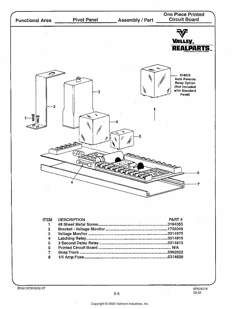
Functional Area Pivot Panel Assembly / Part Circuit Board One Piece Printed 7
- 314815 Auto Reverse Relay Option (Not Included with Standard
Panel)
ITEM 1 2 3 4 5 6 7 8
DESCRIPTION PART # ................................................................ #8 Sheet Metal Screw 064055
- ......................................................... Bracket Voltage Monitor 1702049 ......................................................................... Voltage Monitor 034975
........................................................................... Latching Relay 031 481 5 ............................................................... 3 Second Delay Relay 031 481 3 ................................................................... Printed Circuit Board NIA
Snap Track ................................................................................. 0992022 ............................................................................. 114 Amp Fuse 0314929
Copyright © 2005 Valmont Industries, Inc.
6P50704109-055-7
Quality checked for better irrigation
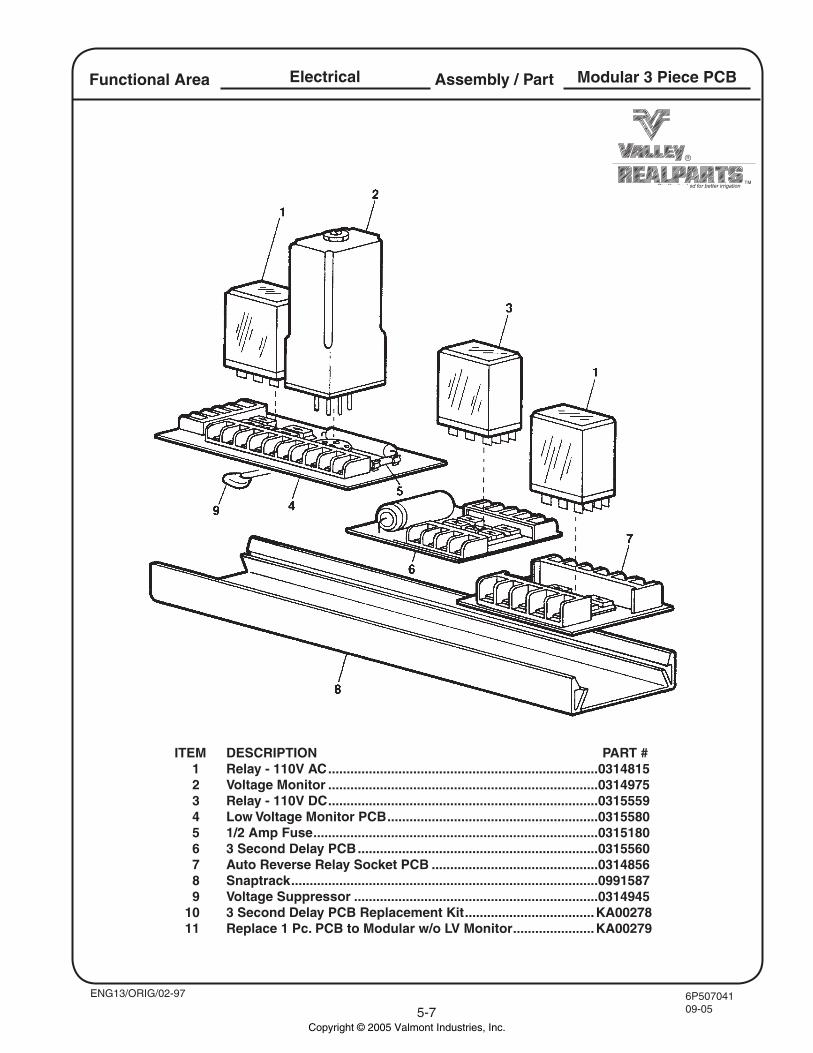
Assembly / PartElectricalFunctional Area Modular 3 Piece PCB
ENG13/ORIG/02-97
ITEM DESCRIPTION PART # 1 Relay - 110V AC .........................................................................0314815 2 Voltage Monitor .........................................................................0314975 3 Relay - 110V DC .........................................................................0315559 4 Low Voltage Monitor PCB .........................................................0315580 5 1/2 Amp Fuse .............................................................................0315180 6 3 Second Delay PCB .................................................................0315560 7 Auto Reverse Relay Socket PCB .............................................0314856 8 Snaptrack ...................................................................................0991587 9 Voltage Suppressor ..................................................................0314945 10 3 Second Delay PCB Replacement Kit ...................................KA00278 11 Replace 1 Pc. PCB to Modular w/o LV Monitor ......................KA00279
Copyright © 2005 Valmont Industries, Inc.
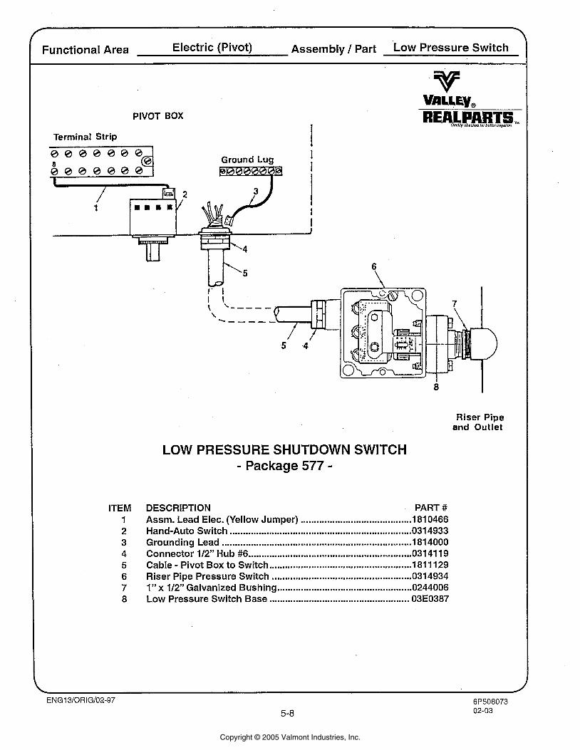
Functional Area Electric (Pivot) Assembly / Part Low Pressure Switch
PIVOT BOX
Terminal Strip
Ground Lug -
ITEM 1 2 3 4 5 6 7 8
Riser Pipe and Outlet
LOW PRESSURE SHUTDOWN SWITCH - Package 577 -
DESCRIPTION PART # Assm. Lead Elec. (Yellow Jumper) ........................................ 181 0466 Hand-Auto Switch ................................................................... 0 3 4933 Grounding Lead ................................................................... 181 4000 Connector 112" Hub #6 .............................................................. 031 41 19 Cable - Pivot Box to Switch ...................................................... 181 1 129
..................................................... Riser Pipe Pressure Switch 034934 I" x 112" Galvanized Bushing ................................................... 0244006 Low Pressure Switch Base ..................................................... 03E0387
Copyright © 2005 Valmont Industries, Inc.
\
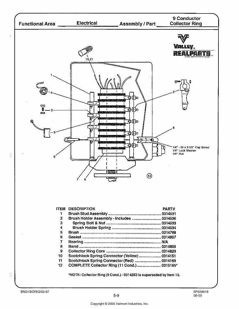
9 Conductor Functional Area Electrical Assembly / Part Collector Ring
Om
2d 8
114" - 20 x 2-112" Cap 114" Lock Washer 114" Nut
ITEM 1 2 3 4 5 6 7 8 9 10 11 12
DESCRIPTION PART# Brush Stud Assembly ................................................ 0314531 Brush Holder Assembly - Includes ........................... 0314536
Spring Bolt & Nut .................................................. 0314533 Brush Holder Spring ............................................. 0314534
Brush ...................................................................... 0314788 Gasket ...................................................................... 031 4807 Bearing ...................................................................... N/A Band ....................................................................... 0314806 Collector Ring Core .................................................. 0314829 Scotchlock Spring Connector (Yellow) .................... 0314151 Scotchlock Spring Connector (Red) ........................ 0314169 COMPLETE Collector Ring (1 1 Cond.) ...................... 0315165*
Screw
*NOTE: Collector Ring (9 Cond.) - 0314253 is superseded by Item 12.
Copyright © 2005 Valmont Industries, Inc.
L
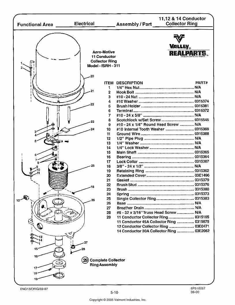
11 .I 2 & 14 Conductor Functional Area Electrical Assembly / Part Collector Ring
Aero-Motive
-- / ' 11 Conductor Collector Ring
Model - ISRH - 311
ITEM 1 2 3 4 5 6 7 8 9
10 11 12 13 14 15 16 17 18 19 20 21 22 23 24 25 26 27 28 29
DESCRIPTION PART# .................................................. 114'' Hex Nut NIA
...................................................... Hook Bolt NIA - ................................................... #I 0 24 Nut NIA
................................................... #I 0 Washer 031 5374 Brush Holder ................................................. 0315381 Terminal ........................................................ 0315372
- .............................................. #lo 24 x 518" NIA Scotchlock w1Set Screw .............................. 0315545
............. . #I0 24 x 114" Round Head Screw NIA #10 Internal Tooth Washer .......................... 0315369 Ground Wire ................................................. 0315388
.............................................. 112" Pipe Plug NIA .................................................. 114" Washer NIA
......................................... 114" Lock Washer NIA Main Shaft .................................................... 0315365 Bearing ......................................................... 0315364 Lock Collar ..................... .. ........................ 0315387
- ............................................. 318" 24 x 112" NIA Retaining Ring ............................................. 0315362
............................................ Extended Cover 03E1496 ........................................................... Gasket 031 5379
Brush Stud .................................................... 0315376 Brush ............................................................ 031 5380 Spring .......................................................... 0315373 Single Collector Ring ................................... 0315383
.............................................................. Base NIA .............................................. Breather Drain NIA
................ . #6 32 x 311 6"Truss Head Screw NIA 11 Conductor Collector Ring ........................ 03151 65 11 Conductor 45A Collector Ring ................ 0315675 12 Conductor Collector Ring ....................... 03E0471
................ 14 Conductor 30A Collector Ring 03E2062
Complete Collector Ring Assembly
Copyright © 2005 Valmont Industries, Inc.
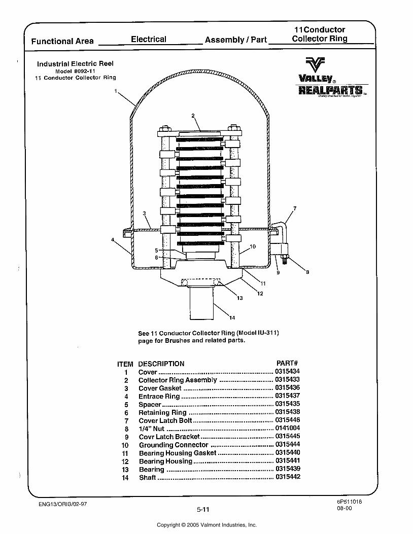
I 11 Conductor
Functional Area Electrical Assembly / Part Collector Ring
Industrial Electric Reel Model 8092-1 1
11 Conductor Collector Ring
4
See 11 Conductor Collector Ring (Model IU-311) page for Brushes and related parts.
ITEM 1 2 3 4 5 6 7 8 9 10 11 12 13 14
DESCRIPTION PART# ............................................................. Cover 031 5434
Collector Ring Assembly ............................. 0315433 Cover Gasket ............................................... 0315436 Entrace Ring ................................................ 0315437 Spacer .......................................................... 031 5435 Retaining Ring ............................................ 0315438 Cover Latch Bolt ........................................... 0315446 114" Nut ........................................................ 01 41 004 Covr Latch Bracket ....................................... 0315445 Grounding Connector ......................... .... 0315444 Bearing Housing Gasket .............................. 0315440 Bearing Housing ........................................... 0315441 Bearing ....................................................... 0315439 Shaft .............................................................. 031 5442
Copyright © 2005 Valmont Industries, Inc.
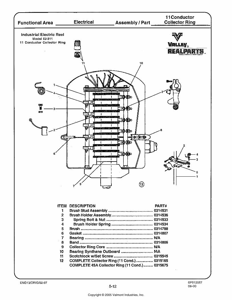
11 Conductor I Functional Area Electrical Assembly 1 Part Collector Ring
I Industrial Electric Reel Model IU-311
11 Conductor Collector Ring
ITEM 1 2 3 4 5 6 7 8 9
10 11 12
DESCRIPTION PART# Brush Stud Assembly .......................................... 0314531 Brush Holder Assembly ....................................... 0314536
Spring Bolt & Nut ........................................... 0314533 Brush Holder Spring ....................................... 0314534
Brush ................................................................... 0314788 Gasket .................................................................. 031 4807 Bearing ............................................................... N/A Band ................................................................. 0314806 Collector Ring Core ............................................ N/A Bearing Synthane Outboard .............................. N\A Scotchlock w/Set Screw ..................................... 0315545 COMPLETE Collector Ring (1 1 Cond.) ................ 0315165 COMPLETE 45A Collector Ring (1 1 Cond.) ......... 0315675
Copyright © 2005 Valmont Industries, Inc.
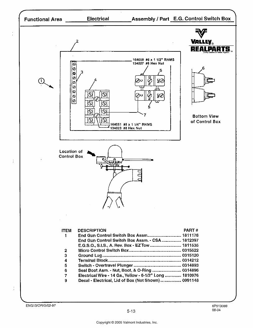
Functional Area Electrical Assembly 1 Part E.G. Control Switch Box
-134023 18 Hex Nut
164058 16 x 1 112" RHMS /q 134027 16 Hex Nut
Location of control BOX %
Bottom View of Control Box
DESCRIPTION PART # ............................. End Gun Control Switch Box Assm 181 1176 - ................. End Gun Control Switch Box Assm. CSA 1812397
- ........................... E.G.S.O., S.I.S., A. Rev. Box EZTow 1811535 ............................................. Micro Control Switch Box 0315522
.................................................................... Ground Lug 0315120 ............................................................... Terminal Block 031 421 2
......................................... . Switch Overtravel Plunger 0314893 ......................... Seal Boot Asm. - Nut, Boot, & 0-Ring 0314896
- .............. Electrical Wire - 14 Ga.,Yellow 6-1/2" Long 181 0976 .................. . Decal Electrical, Lid of Box (Not Shown) 0991 148
Copyright © 2005 Valmont Industries, Inc.
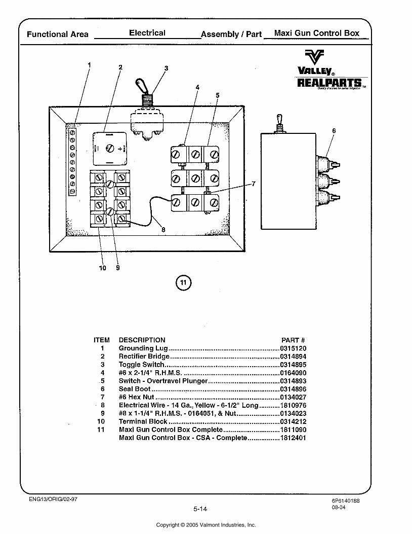
Functional Area Electrical Assembly / Part Maxi Gun Control Box
ITEM 1 2 3 4 5 6 7 8 9 10 11
DESCRIPTION PART # Grounding Lug .......................................................... 031 51 20 Rectifier Bridge ....................................................... 031 4894 Toggle Switch ............................................................ 031 4895 #6 x 2-114" R.H.M.S. .................................................. 0164090 Switch . Overtravel Plunger ...................................... 0314893 Seal Boot .................................................................... 0 4896 #6 Hex Nut ................................................................. 0134027 Electrical Wire . 14 Ga..Yellow . 6-112" Long ........... 1810976 #8 x 1-114" R.H.M.S. . 0164051. & Nut ....................... 0134023 Terminal Block ........................................................ 031421 2 Maxi Gun Control Box Complete .............................. 181 1090 Maxi Gun Control Box . CSA . Complete ................. 1812401
Copyright © 2005 Valmont Industries, Inc.
C End-of-Field Stop,
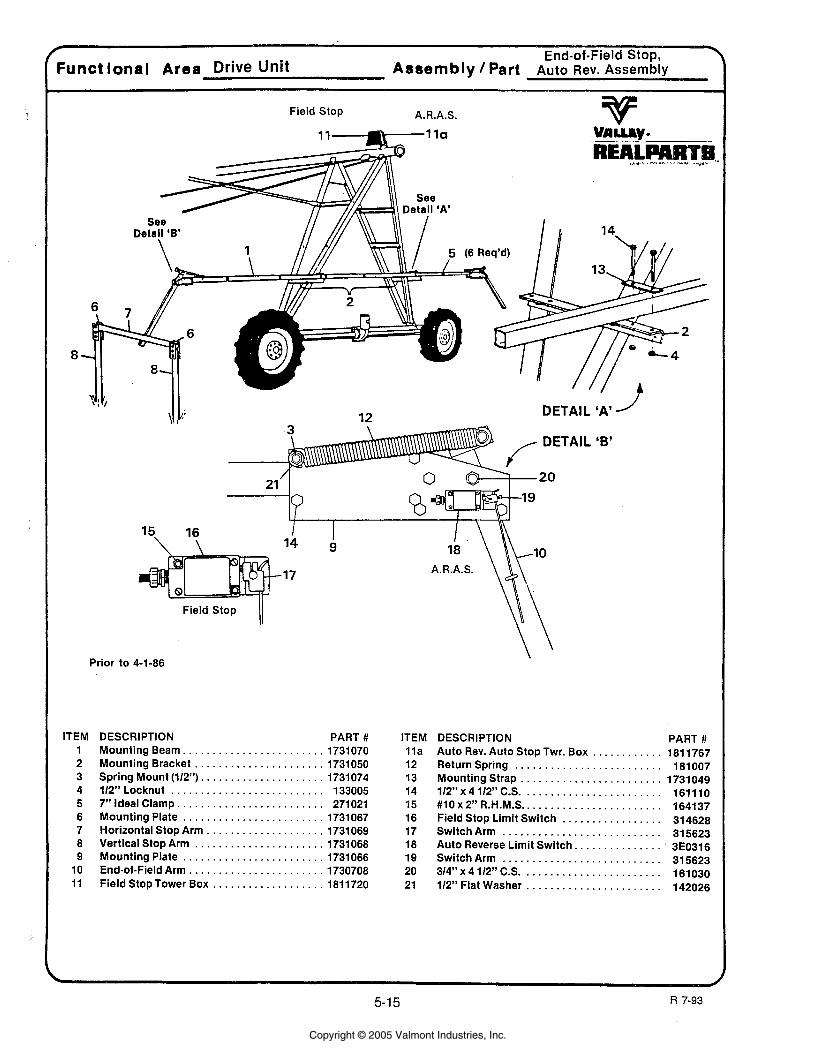
Funct lonal Area Drive Unit Assembly/Part Auto Rev.Assembly
Field Stop A.R.A.S.
Field Stop 11 Prior to 4-1-86
ITEM DESCRIPTION 1 Mounting Beam.. . . . . . . . . . . . . . . . .
9
PART # 1731 070 . . . . -
Mounting Bracket . . . . . . . . . . . . . . . . . . . . . . 1731050 Spring Mount (112"). . . . . . . . . . . . . . . . . . . . . 1731074 112" Locknut . . . . . . . . . . . . . . . . . . . . . . . . . . 133005 7" Ideal Clamp . . . . . . . . . . . . . . . . . . . . . . . . . 271021 Mounting Plate . . . . . . . . . . . . . . . . . . . . . . . . 1731067 Horizontal Stop Arm . . . . . . . . . . . . . . . . . . . . 1731069 Vertical Stop Arm . . . . . . . . . . . . . . . . . . . . . . 1731068 Mounting Plate . . . . . . . . . . . . . . . . . . . . . . . . 1731066 End-of-Field Arm . . . . . . . . . . . . . . . . . . . . . . . 1730708 Field Stop Tower Box . . . . . . . . . . . . . . . . . . . 1811720
ITEM l l a 12 13 14 45 16 17 18 19 20 21
DESCRIPTION PART # Auto Rev. Auto Stop Twr. Box . . . . . . . . . . . . 181 1767 Return Spring . . . . . . . . . . . . . . . . . . . . . . . . . 181007 Mounting Strap . . . . . . . . . . . . . . . . . . . . . . . . 1731049 112"x4 112" C.S. . . . . . . . . . . . . . . . . . . . . . . . 161110
. . . . . . . . . . . . . . . . . . . . . . . . #lOx2"R.H.M.S 164137 Field Stop Limit Switch . . . . . . . . . . . . . . . . . 314628 SwitchArm . . . . . . . . . . . . . . . . . . . . . . . . . . . 315623 Auto Reverse Limit Switch.. . . . . . . . . . . . . . . 3E0316 SwitchArm . . . . . . . . . . . . . . . . . . . . . . . . . . . 315623 3/4"~41/2"c.s. . . . . . . . . . . . . . . . . . . . . . . . 161030 112" Flat Washer . . . . . . . . . . . . . . . . . . . . . . . 142026
Copyright © 2005 Valmont Industries, Inc.
C
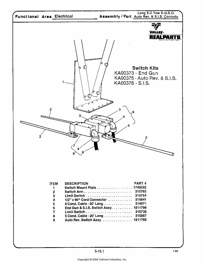
Long E-z TOW E.G.S.O. Funct ional Area Electrical Assembly Part A U ~ O Rev . & S.I.S. Controls
ITEM 1 2 3 4 5 6 7 8 9
DESCRIPTION PART # . . . . . . . . . . . . . . . . . . . Switch Mount Plate 1745032
. . . . . . . . . . . . . . . . . . . . . . . . . . Switch Arm 31 5765 . . . . . . . . . . . . . . . . . . . . . . . . . Limit Switch 315754
. . . . . . . . . . . . . 112" x 90° Cord Connector 31 5641 . . . . . . . . . . . . . . . . 4 Cond . Cable 20' Long 314571
. . . . . . . . . . . End Gun & S.I.S. Switch Assy 1811796 . . . . . . . . . . . . . . . . . . . . . . . . . Limit Switch 315738 . . . . . . . . . . . . . . . . 5 Cond . Cable 20' Long 31 5967
. . . . . . . . . . . . . . . . . . Auto Rev Switch Assy 1811769
Copyright © 2005 Valmont Industries, Inc.
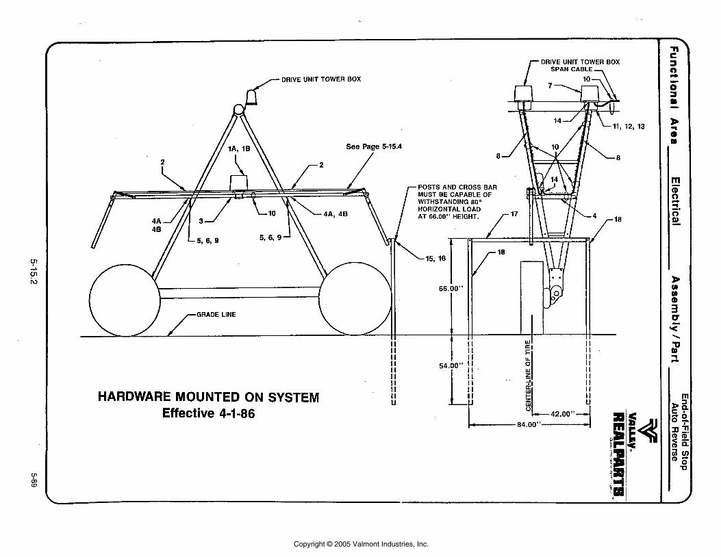
DRIVE UNlT TOWER BOX f SPAN CABLE,
DRIVE UNIT TOWER BOX
See Page 5-15.4
POSTS AND CROSS BAR MUST BECAPABLEOF WITHSTANDING 80° HORIZONTAL LOAD AT 66.00" HEIGHT.
HARDWARE MOUNTED ON SYSTEM Effective 4-1-86
Copyright © 2005 Valmont Industries, Inc.

Parts List End-of-Field StoplAuto Reverse
I
For Page 5-1 5.2
End-of-Field Stop 'Funct lonal Area
\
Electrical Assembly Part Auto Reverse
v vnLLIy* REAL ad... . Th..h...rm..r. . ..*. ...
ITEM 1A 1B
2 3
4A 4 B
5 6 7 8 9
10 11 12 13 14 15 16 17 18 19
DESCRIPTION PART # . . . . . . . . . . . . Auto Rev./Auto Stop Box 1812340
. . . . . . . . . . . . . . . End-of-Field Stop Box 181 2341 . . . . . . . . . . . . . . . . . . . . . Actuator Tube 1731 376 . . . . . . . . . . . . . . . . . . . . Mounting Beam 1731383
Mount . . . . . . . . . . . . . . . . . . . . . . . . . . . . 1731387 . . . . . . . . . . . . . . . . . . Mount Low Profile 1780768
112" Locknut . . . . . . . . . . . . . . . . . . . . . . 133005 . . . . . . . . . . . . . . . . . . . 112" Flat Washer 142026
. . . . . . . . . . . . . . . . . . . . . . Junction Box +Wl76+ 19 14Y I 0 . . . . . . . . . . 15' 11 Wire Electrical Cable 1812012
. . . . . . . . . . . . 112" x 1-112" Cap Screw 161026 . . . . . . . . . . . . . . . . . . . . . . . . . . . . Clamp 271021
. . . . . . . . . . . . . . 114" x 314" Cap Screw 161057 114" Locknut . . . . . . . . . . . . . . . . . . . . . . 133008
. . . . . . . . . . . . . . Control Box Mtg . Plate 1700494 . . . . . . . . . . . . . . . . . . . . Cord Connector 31 4466
112" Locknut . . . . . . . . . . . . . . . . . . . . . . 133005 . . . . . . . . . . . . 112" x 5-112" Cap Screw 161018
. . . . . . . . . . . . . . . . Horizontal Stop Arm 1731 368 . . . . . . . . . . . . . . . . . . Vertical Stop Arm 1731 384
. . . . . . . . . . . . . . . Aras Pivot Hardware KA00811
Add End of Field Stop 0000A74 . . . . . Add End of Field Auto Reverse 0000A75 .. . . . .
* * Add End of Field Post for A74 or A75
* * * * Add End of Field Barriers A99
Copyright © 2005 Valmont Industries, Inc.
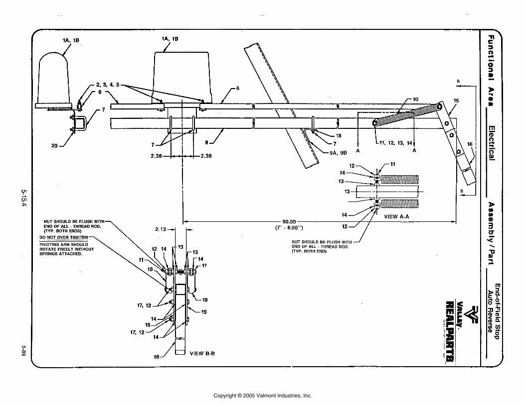
NUT SHOULD BE FLUSH WITH END OF ALL - THREAD ROD. (TYP. BOTH ENDS)
DO NOT OVER TIGHTEN
PIVOTING ARM SHOULD ROTATE FREELY WITHOUT SPRINGS ATTACHED.
END OF ALL - THREAD ROD. (TYP. BOTH END)
Copyright © 2005 Valmont Industries, Inc.
........... . .
Funct ional Area Electrical Assembly 1 Part ~ u t o Reverse
v vniuy- REAL Own .. . , ... p..... rw.. .. .,a ,.. .. *-
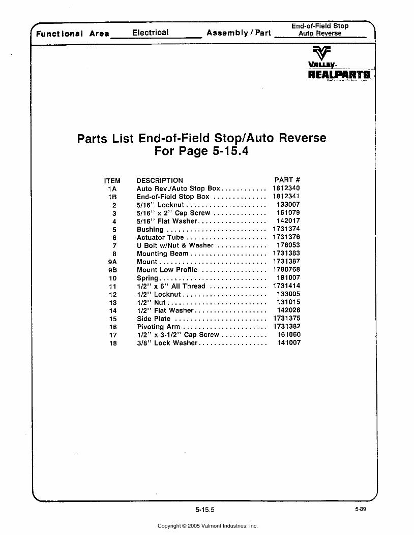
Parts List End-of-Field StoplAuto Reverse For Page 5-15.4
ITEM 1A 1B
2 3 4 5 6 7 8
9A 9 B 10 11 12 13 14 15 16 17 18
DESCRIPTION . . . . . . . . . . . . Auto RevJAuto Stop Box
End-of-Field Stop Box . . . . . . . . . . . . . . . . . . . . . . . . . . . . . . . . . . . Sl l 6" Locknut
. . . . . . . . . . . . . . 5/16" x 2" Cap Screw 5/16" Flat Washer . . . . . . . . . . . . . . . . . . Bushing . . . . . . . . . . . . . . . . . . . . . . . . . . Actuator Tube . . . . . . . . . . . . . . . . . . . . .
. . . . . . . . . . . . . U Bolt w/Nut & Washer . . . . . . . . . . . . . . . . . . . . Mounting Beam
Mount . . . . . . . . . . . . . . . . . . . . . . . . . . . . . . . . . . . . . . . . . . . . . Mount Low Profile
Spring . . . . . . . . . . . . . . . . . . . . . . . . . . . . 112" x 6" All Thread . . . . . . . . . . . . . . . 112" Locknut . . . . . . . . . . . . . . . . . . . . . .
. . . . . . . . . . . . . . . . . . . . . . . . . . 112" Nut 112" Flat Washer . . . . . . . . . . . . . . . . . . . Side Plate . . . . . . . . . . . . . . . . . . . . . . . .
. . . . . . . . . . . . . . . . . . . . . . Pivoting Arm 112" x 3-112" Cap Screw . . . . . . . . . . . . 318" Lock Washer . . . . . . . . . . . . . . . . . .
PART # 181 2340 181 2341
133007 161 079 14201 7
1731 374 1731 376 176053
1731 383 1731 387 1780768
181 007 1731414 133005 131015 142026
1731 375 1731 382 161 060 141 007
Copyright © 2005 Valmont Industries, Inc.
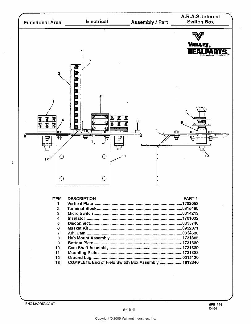
A.R.A.S. Internal - Functional Area Electrical Assembly 1 Part Switch Box
ITEM 1 2 3 4 5 6 7 8 9 10 11 12 13
DESCRIPTION PART # Vertical Plate .............................................................................. 1702053 Terminal Block ........................................................................... 031 5485 Micro Switch ........................................................................... 031 421 3 Insulator .................................................................................. 1701632 Disconnect ................................................................................ 031 5746 Gasket Kit .................................................................................. 0992071 Adj. Cam ..................................................................................... 031 4630 Hub Mount Assembly ............................................................... 1731385 Bottom Plate ......................................................................... 1731380 Cam Shaft Assembly ................................................................ 1731389 Mounting Plate .................................................................... 1731 388 Ground Lug ........................................................................... 031 51 20 COMPLETE End of Field Switch Box Assembly .................... 1812340
Copyright © 2005 Valmont Industries, Inc.
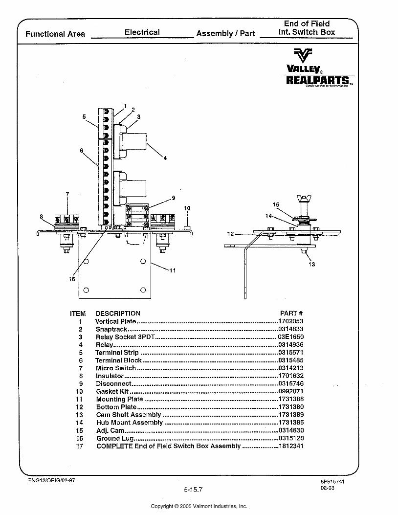
r End of Field Y
Functional Area Electrical Assembly 1 Part Int. Switch Box
ITEM 1 2 3 4 5 6 7 8 9
10 11 12 13 14 15 16 17
DESCRIPTION PART # Vertical Plate ............................................................................. 1702053 Snaptrack ............................................................................ 031 4833 Relay Socket 3PDT ................................................................... 03E1650
........................................................................................... Relay 031 4936 Terminal Strip ............................................................................ 0315571 Terminal Block ......................................................................... 031 5485 Micro Switch .......................................................................... 031 421 3 Insulator ..................................................................................... 1701 632 Disconnect ................................................................................. 031 5746 Gasket Kit .................................................................................. 0992071 Mounting Plate .......................................................................... 1731388 Bottom Plate ........................................................................... 1731380 Cam Shaft Assembly ................................................................ 1731 389 Hub Mount Assembly ............................................................... 1731385 Adj. Cam .................................................................................. 031 4630 Ground Lug ............................................................................. 031 51 20
.................... COMPLETE End of Field Switch Box Assembly 181 2341
Copyright © 2005 Valmont Industries, Inc.
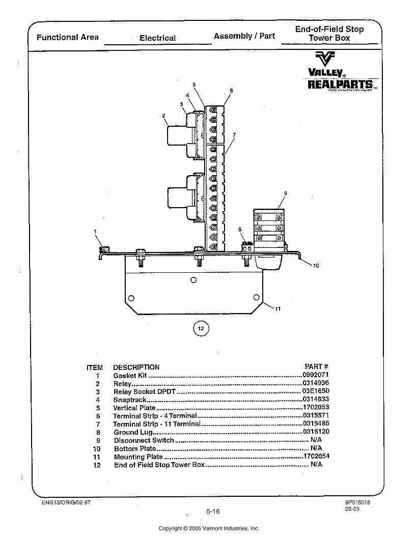
\ End-of-Field Stop
Functional Area Electrical Assembly 1 Part Tower Box
ITEM 1 2 3 4 5 6 7 8 9 10 11 12
DESCRIPTION PART # Gasket Kit .................................................................................. 0992071 Relay ........................................................................................... 031 4936 Relay Socket DPDT ................................................................ 03El650 Snaptrack ............................................................................. 031 4833 Vertical Plate .............................................................................. 702053
- ........................................................ Terminal Strip 4 Terminal 031 5571 . Terminal Strip 11 Terminal ................................................. 0315485
Ground Lug .............................................................................. 031 51 20 Disconnect Switch .................................................................... NIA Bottom Plate .............................................................................. NIA Mounting Plate .......................................................................... 1702054 End of Field Stop Tower Box ..................................................... NIA
Copyright © 2005 Valmont Industries, Inc.
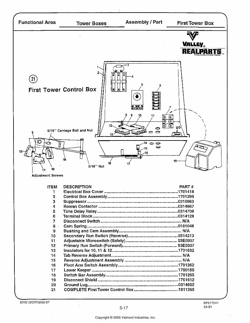
Functional Area Tower Boxes Assembly / Part First Tower Box
First Tower Control Box
12
Adjustment Screws
ITEM 1 2 3 4 5 6 7 8 9
10 11 12 13 14 15 16 17 18 19 20 21
DESCRIPTION PART # Electrical Box Cover ................................................................. 1701 41 8 Control Box Assembly ........................................................... 1701299 Suppressor ................................................................................ 031 5663 Rowan Contactor .................................................................... 031 4667 Time Delay Relay .................................................................... 031 4708 Terminal Block ....................................................................... 031 41 29 Disconnect Switch .................................................................. NIA Cam Spring ................................................................................ 0 81 046 Bushing and Cam Assembly ................................................... NIA
............................................ Secondary Run Switch (Reverse) 031 421 3 Adjustable Microswitch (Safety) ........................................... 03E0307 Primary Run Switch (Forward) .............................................. 03E0307 Insulators for 10, 11 & 12 .......................................................... 1701632 Tab Reverse Adjustment ............................................................ NIA
.................................................. Reverse Adjustment Assembly NIA Pivot Arm Switch Assembly .................................................... 1701 262 Lower Keeper ............................................................................ 1700156 Switch Bar Assembly .............................................................. 1701 295 Disconect Shield ..................................................................... 1701 61 2 Ground Lug .......................................................................... 0314682
....................................... COMPLETE First Tower Control Box 181 1265
Copyright © 2005 Valmont Industries, Inc.
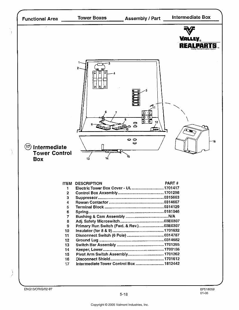
Functional Area Tower Boxes Assembly I Part Intermediate Box
@ lntermediate Tower Control Box
ITEM 1 2 3 4 5 6 7 8 9
10 11 12 13 14 15 16 17
DESCRIPTION PART # Electric Tower Box Cover . UL ............................. 1701 41 7 Control Box Axxembly ......................................... 1701 298
............................................................ Suppressor 031 5663 Rowan Contactor ................................................. 031 4667 Terminal Block ...................................................... 031 41 29 Spring ..................................................................... 01 81 046 Bushing & Cam Assembly ....................................... NIA Adj . Safety Microswitch ........................................ 03E0307 Primary Run Switch (Fwd . & Rev.) ....................... 03E0307 Insulator (for 8 & 9) ............................................. 1701 632 Disconnect Switch (6 Pole) .................................. 0314787 Ground Lug ........................................................... 0314682 Switch Bar Assembly ........................................... 1701295 Keeper. Lower ...................................................... 17001 56 Pivot Arm Switch Assembly ................................. 1701 262
................................................. Disconnect Shield 1701 61 2 Intermediate Tower Control Box .......................... 181 2442
Copyright © 2005 Valmont Industries, Inc.
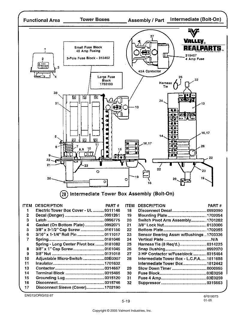
Small Fuse Block 45 Amp Fusing
3-Pole Fuse Block - 315462
Functional Area Tower Boxes Assembly 1 Part Intermediate (Bolt-On)
ITEM 1 2 3 4 5 6 7
8 9
10 11 13 14 15 16 17
- 315457 4 Amp Fuse
45A Contactor 'Y Tie Harness 6' CY"
@ Intermediate Tower Box Assembly (Bolt-On)
DESCRIPTION PART # ITEM DESCRIPTION PART # Electric Tower Box Cover - UL .......... 931 11 46 18 Disconnect Decal ............................... 0992090 Decal (Danger) ................................... 099126 19 Mounting Plate ................................... 1702054 Latch ................................................... 0996775 20 Switch Pivot Arm Assembly .............. 1701262 Gasket (On Bottom Plate) ................. 0992071 21 318" Lock Nut ...................................... 01 33006 318" x 3-112" Cap Screw ..................... 01 61 150 22 Bottom Plate ....................................... 1702055 3/16" x 1-114" Roll Pin ........................ 01 11017 23 Sensor Bearing Assm w1Bushings ..I703336 Spring .................................................. 0181 046 24 Vertical Plate .......................................... NIA Spring - Long Center Pivot box ........ 01 81 082 25 Harness Tie (8 Req'd.) ........................ 031 4225 318" x I" Cap Screw ............................ 0161045 26 Snap Bushing ..................................... 0992070 318'' Nut ............................................... 013101 8 27 3 HP Contactor w1Fuseblock ............ 031 5464 Adjustable Micro-Switch ................... O3E0307 28 Intermediate Tower Box - L.C.P.A ...... 181 1698 Insulator .............................................. 1701632 Intermediate Tower Box ..................... 181 2442 Contactor ........................................... 031 4667 29 Slow Down Timer ............................... 0000955 Terminal Block ................................... 031 5485 30 Fuse Block .......................................... 03E0258
. Grounding Lug ................................... 0315120 31 Fuse 4 Amp ......................................... 03E0259 Disconnect ......................................... 0315746 32 Suppressor ......................................... 031 5663 Disconnect Sleeve (Cover) ................ 17021 90 I
Copyright © 2005 Valmont Industries, Inc.
6EL5203803-105-20
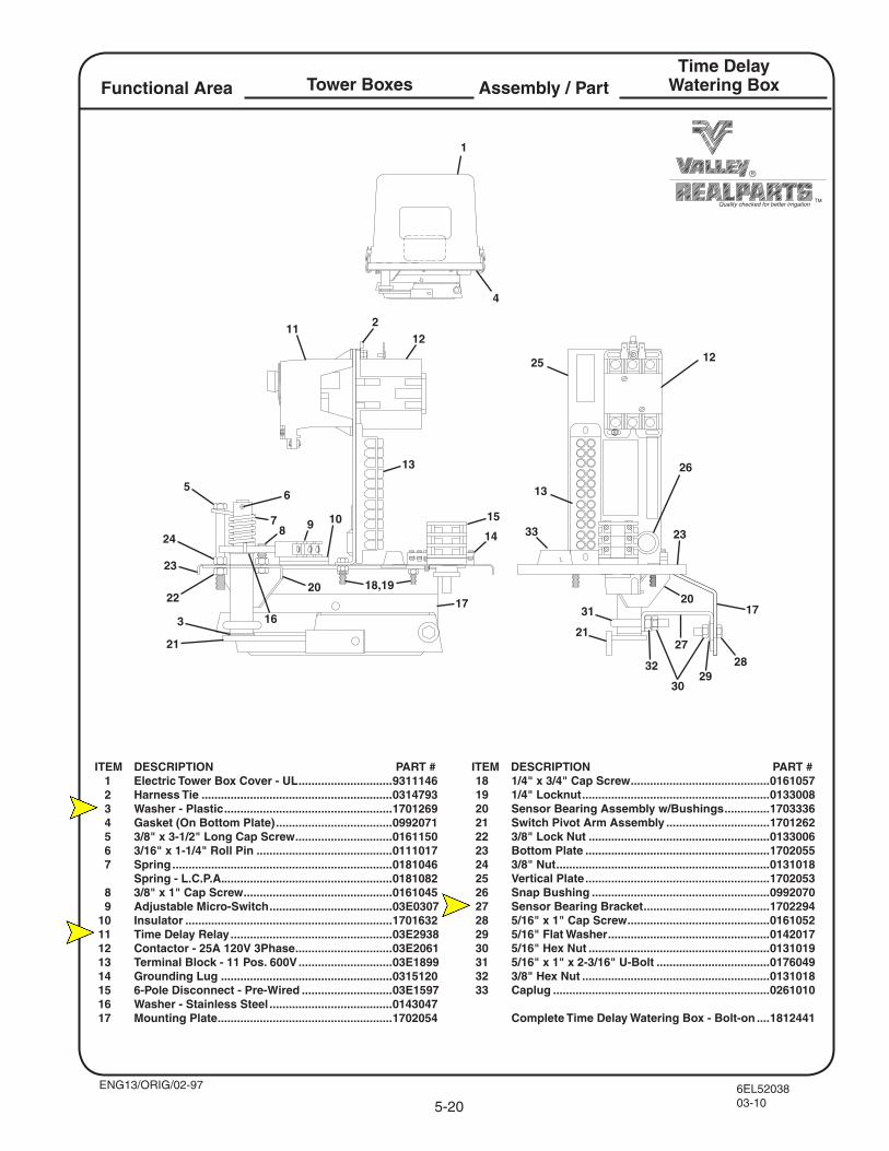
Assembly / PartFunctional AreaTime Delay
Watering Box
ITEM DESCRIPTION PART #
Quality checked for better irrigation
1
4
56
78 9 10
12
12
13
13
14
15
18,1922
24
25
26
23
23
17
2121
2020
17
11
18 1/4" x 3/4" Cap Screw ...........................................0161057 19 1/4" Locknut ..........................................................0133008 20 Sensor Bearing Assembly w/Bushings ..............1703336 21 Switch Pivot Arm Assembly ................................1701262 22 3/8" Lock Nut ........................................................0133006 23 Bottom Plate .........................................................1702055 24 3/8" Nut ..................................................................0131018 25 Vertical Plate .........................................................1702053 26 Snap Bushing .......................................................0992070 27 Sensor Bearing Bracket .......................................1702294 28 5/16" x 1" Cap Screw ............................................0161052 29 5/16" Flat Washer ..................................................0142017 30 5/16" Hex Nut ........................................................0131019 31 5/16" x 1" x 2-3/16" U-Bolt ...................................0176049 32 3/8" Hex Nut ..........................................................0131018 33 Caplug ...................................................................0261010
Complete Time Delay Watering Box - Bolt-on ....1812441
ITEM DESCRIPTION PART # 1 Electric Tower Box Cover - UL .............................9311146 2 Harness Tie ...........................................................0314793 3 Washer - Plastic ....................................................1701269 4 Gasket (On Bottom Plate) ....................................0992071 5 3/8" x 3-1/2" Long Cap Screw ..............................0161150 6 3/16" x 1-1/4" Roll Pin ..........................................0111017 7 Spring ....................................................................0181046 Spring - L.C.P.A. ....................................................0181082 8 3/8" x 1" Cap Screw ..............................................0161045 9 Adjustable Micro-Switch ......................................03E0307 10 Insulator ................................................................1701632 11 Time Delay Relay ..................................................03E2938 12 Contactor - 25A 120V 3Phase ..............................03E2061 13 Terminal Block - 11 Pos. 600V .............................03E1899 14 Grounding Lug .....................................................0315120 15 6-Pole Disconnect - Pre-Wired ............................03E1597 16 Washer - Stainless Steel ......................................0143047 17 Mounting Plate ......................................................1702054
ENG13/ORIG/02-97
Tower Boxes
2
3 16
2728
2930
31
32
33
6EL5213801-105-21
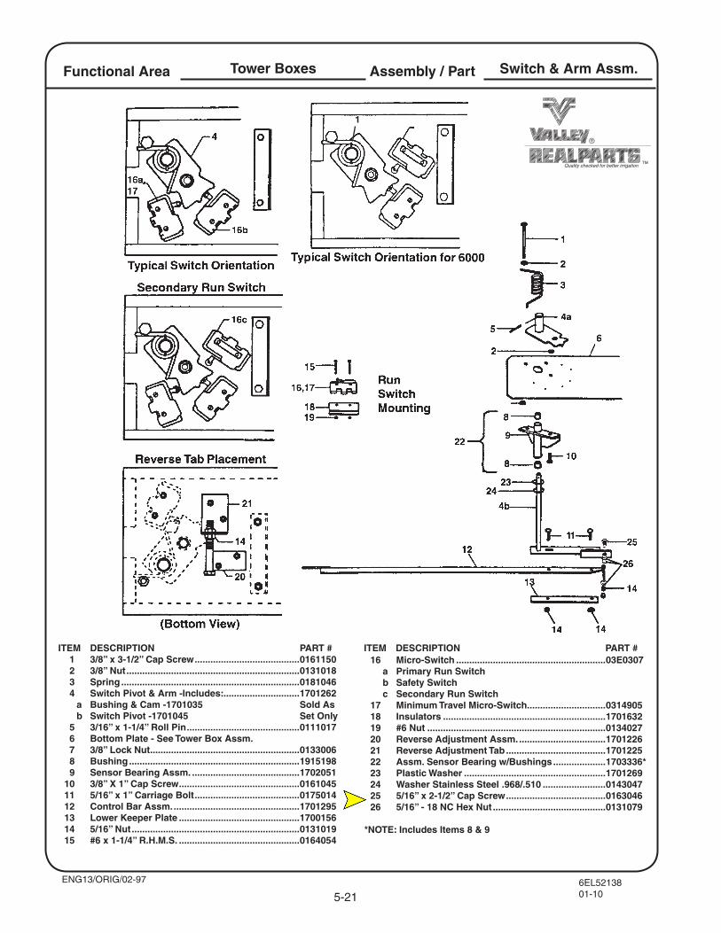
Assembly / PartFunctional Area Switch & Arm Assm.
ITEM DESCRIPTION PART #
Quality checked for better irrigation
1
16 Micro-Switch .........................................................03E0307 a Primary Run Switch b Safety Switch c Secondary Run Switch 17 Minimum Travel Micro-Switch..............................0314905 18 Insulators ..............................................................1701632 19 #6 Nut ....................................................................0134027 20 Reverse Adjustment Assm. .................................1701226 21 Reverse Adjustment Tab ......................................1701225 22 Assm. Sensor Bearing w/Bushings ....................1703336* 23 Plastic Washer ......................................................1701269 24 Washer Stainless Steel .968/.510 ........................0143047 25 5/16” x 2-1/2” Cap Screw ......................................0163046 26 5/16” - 18 NC Hex Nut ...........................................0131079
*NOTE: Includes Items 8 & 9
ITEM DESCRIPTION PART # 1 3/8” x 3-1/2” Cap Screw ........................................0161150 2 3/8” Nut ..................................................................0131018 3 Spring ....................................................................0181046 4 Switch Pivot & Arm -lncludes: .............................1701262 a Bushing & Cam -1701035 Sold As b Switch Pivot -1701045 Set Only 5 3/16” x 1-1/4” Roll Pin ...........................................0111017 6 Bottom Plate - See Tower Box Assm. 7 3/8” Lock Nut .........................................................0133006 8 Bushing .................................................................1915198 9 Sensor Bearing Assm. .........................................1702051 10 3/8” X 1” Cap Screw ..............................................0161045 11 5/16” x 1” Carriage Bolt ........................................0175014 12 Control Bar Assm. ................................................1701295 13 Lower Keeper Plate ..............................................1700156 14 5/16” Nut ................................................................0131019 15 #6 x 1-1/4” R.H.M.S. ..............................................0164054
ENG13/ORIG/02-97
Tower Boxes
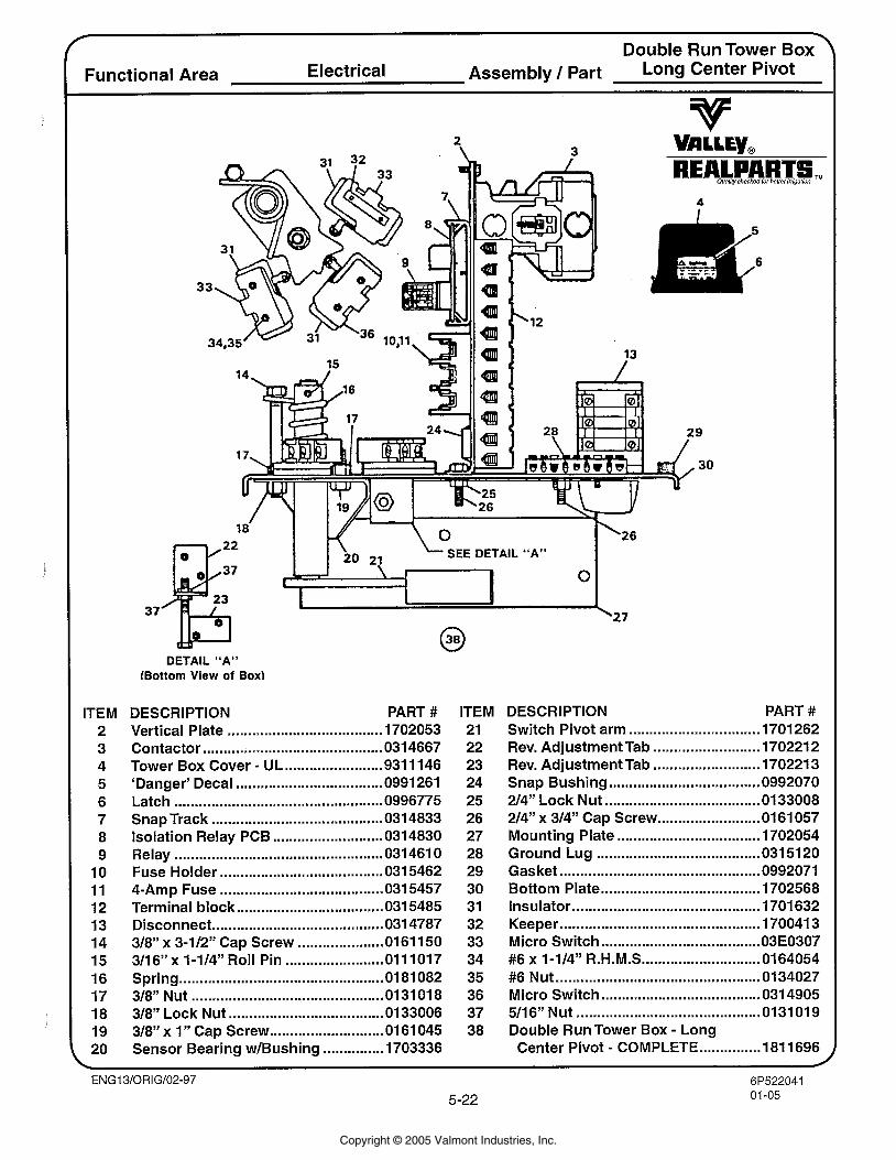
Double Run Tower Box Functional Area Electrical Assembly l Part Long Center Pivot
DETAIL "A" (Bottom View of Box)
ITEM 2 3 4 5 6 7 8 9
10 11 12 13 14 15 16 17 18 19 20
DESCRIPTION PART # Vertical Plate ...................................... 1702053 Contactor ............................................ 031 4667
........................ Tower Box Cover . U L 931 11 46 'Danger' Decal .................................... 0991 261 Latch .................................................. 0996775 Snap Track .......................................... 031 4833 Isolation Relay PCB ........................... 0314830 Relay .................................................. 031 461 0 Fuse Holder ........................................ 031 5462 4-Amp Fuse ........................................ 031 5457 Terminal block .................................... 031 5485 Disconnect ......................................... 031 4787
..................... 318" x 3-112'' Cap Screw 01 61 150 3/16" x 1-114" Roll Pin ........................ 01 11017 Spring ................................................. 0 81 082 318" Nut ............................................... 01 31 01 8 318" Lock Nut ...................................... 01 33006 318" x 1 . Cap Screw ............................ 01 61 045 Sensor Bearing w1Bushing ............... 1703336
ITEM 21 22 23 24 25 26 27 28 29 30 31 32 33 34 35 36 37 38
DESCRIPTION PART # ................................ Switch Pivot arm 1701 262
.......................... . Rev Adjustment Tab 1702212
.......................... . Rev Adjustment Tab 1702213 Snap Bushing ..................................... 0992070 2/4" Lock Nut ...................................... 0133008 2/4" x 314" Cap Screw ......................... 01 61 057
................................... Mounting Plate 1702054 ........................................ Ground Lug 031 51 20
................................................. Gasket 0992071 ....................................... Bottom Plate 1702568
.............................................. Insulator 1701 632 ................................................. Keeper 170041 3
....................................... Micro Switch O3E0307 ............................. #6 x 1-114" R.H.M.S 0164054
.................................................. #6 Nut 01 34027 ....................................... Micro Switch 031 4905
............................................. 5/16" Nut 0131019 Double Run Tower Box . Long
. ............... Center Pivot COMPLETE 181 1696
Copyright © 2005 Valmont Industries, Inc.
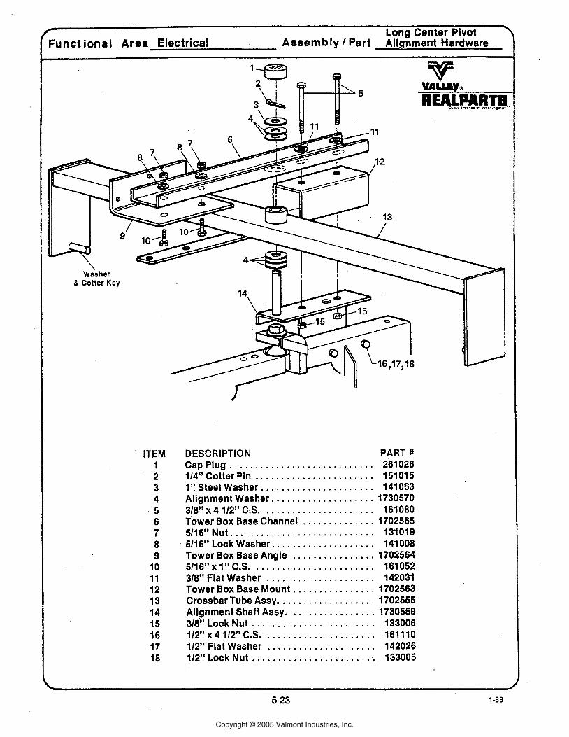
Long Center Pivot Funct lonal Area Electrical Assembly Part Alignment Hardware
ITEM 1 2 3 4 5 6 7 8 9
10 11 12 13 14 15 16 17 18
DESCRIPTION PART # . . . . . . . . . . . . . . . . . . . . . . . . . . . . Cap Plug 261 026
. . . . . . . . . . . . . . . . . . . . . . . 114" Cotter Pin 151015 . . . . . . . . . . . . . . . . . . . . . . 1'' Steel Washer 141063
Alignment Washer . . . . . . . . . . . . . . . . . . . . 1730570 . . . . . . . . . . . . . . . . . . . . . 318" x 4 112" C..S. 161080
Tower Box Base Channel . . . . . . . . . . . . . . 1702565 . . . . . . . . . . . . . . . . . . . . . . . . . . . . 5116" Nut 131019
. . . . . . . . . . . . . . . . . . . . 5116" Lock Washer 141008 Tower Box Base Angle . . . . . . . . . . . . . . . . 1702564
. . . . . . . . . . . . . . . . . . . . . . . 5116"xl"C.S. 161052 . . . . . . . . . . . . . . . . . . . . . 318" Flat Washer 142031
Tower Box Base Mount . . . . . . . . . . . . . . . . 1702563 CrossbarTube Assy . . . . . . . . . . . . . . . . . . . 1702555 Alignment Shaft Assy . . . . . . . . . . . . . . . . . 1730559 318" Lock Nut . . . . . . . . . . . . . . . . . . . . . . . . 133006 112" x 4 112" C.S. . . . . . . . . . . . . . . . . . . . . . 161110 112" Flat Washer . . . . . . . . . . . . . . . . . . . . . 142026
. . . . . . . . . . . . . . . . . . . . . . . . . 112"LockNut 133005
Copyright © 2005 Valmont Industries, Inc.
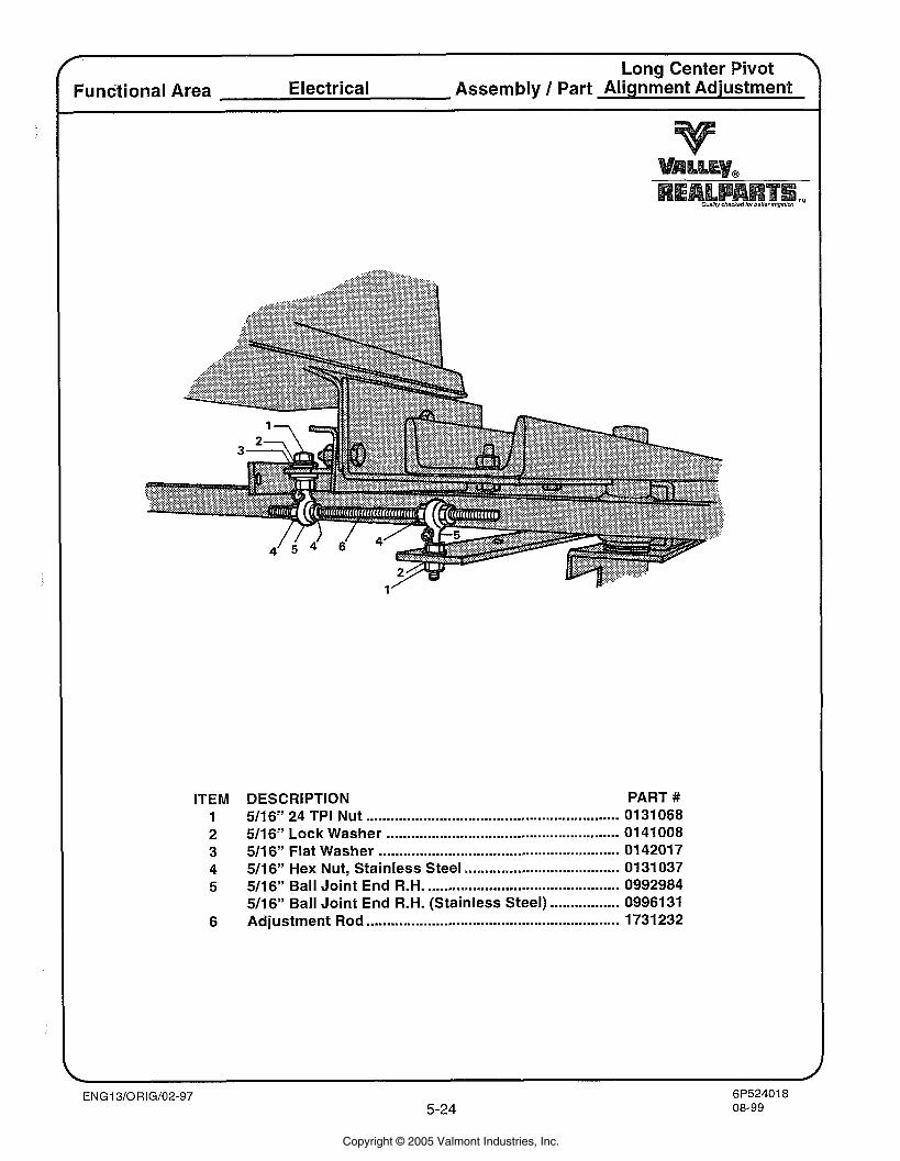
7 Long Center Pivot Functional Area Electrical Assembly 1 Part Alignment Adjustment -
1
ITEM DESCRIPTION PART # 1 5/16" 24 TPI Nut ............................................................. 0131068 2 511 6" Lock Washer ......................................................... 0141 008 3 5/16" Flat Washer .......................................................... 0142017
...................................... 4 511 6" Hex Nut, Stainless Steel 0131037 5 511 6" Ball Joint End R.H. .............................................. 0992984
................. 511 6" Ball Joint End R.H. (Stainless Steel) 0996131 6 Adjustment Rod .............................................................. 1731232
Copyright © 2005 Valmont Industries, Inc.
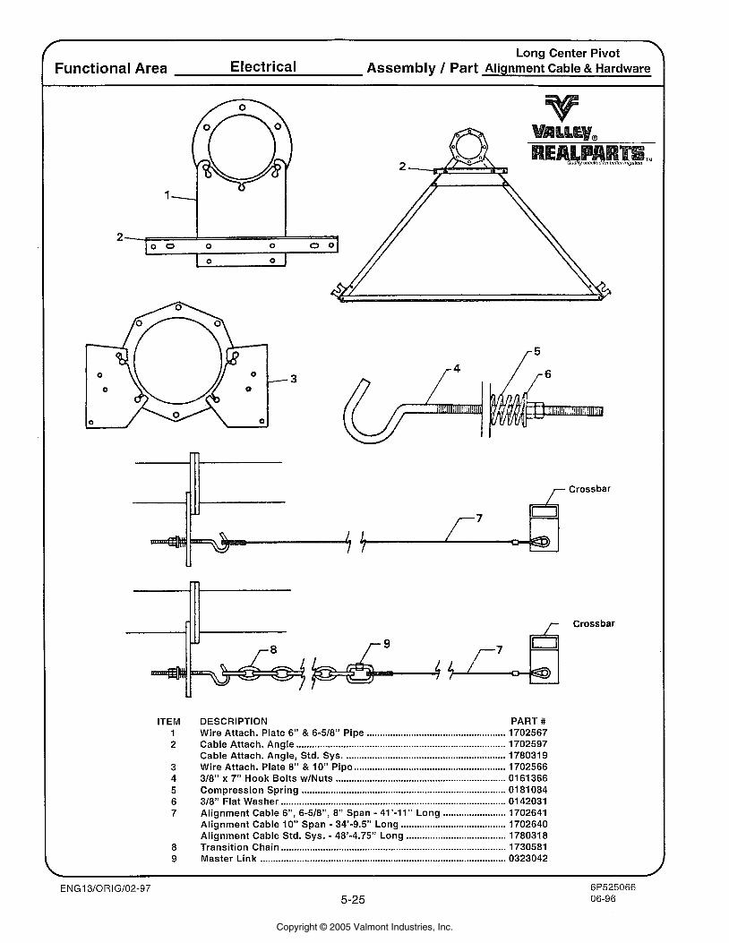
Long Center Pivot Functional Area Electrical Assembly 1 Part Alignment Cable & Hardware
7 Crossbar
ITEM 1 2
DESCRIPTION PART # ..................................................... Wire Attach . Plate 6" & 6-518" Pipe 1702567
Cable Attach . Angle ................................................................................ 1702597 Cable Attach . Angle. Std . Sys .............................................................. 178031 9
.......................................................... Wire Attach . Plate 8" & 10" Pipe 1702566 318" x 7" Hook Bolts w1Nuts ................................................................. 0161366 Compression Spring .............................................................................. 01 81 084 318" Flat Washer ...................................................................................... 0142031
. ........................ Alignment Cable 6". 6.518". 8" Span 41'-11" Long 1702641 ........................................ Alignment Cable 10" Span . 34'.9.5" Long 1702640 ...................................... Alignment Cable Std . Sys .. 48'.4.75" Long 1780318
Transition Chain ...................................................................................... 1730581 Master Link .............................................................................................. 0323042
Crossbar
Copyright © 2005 Valmont Industries, Inc.
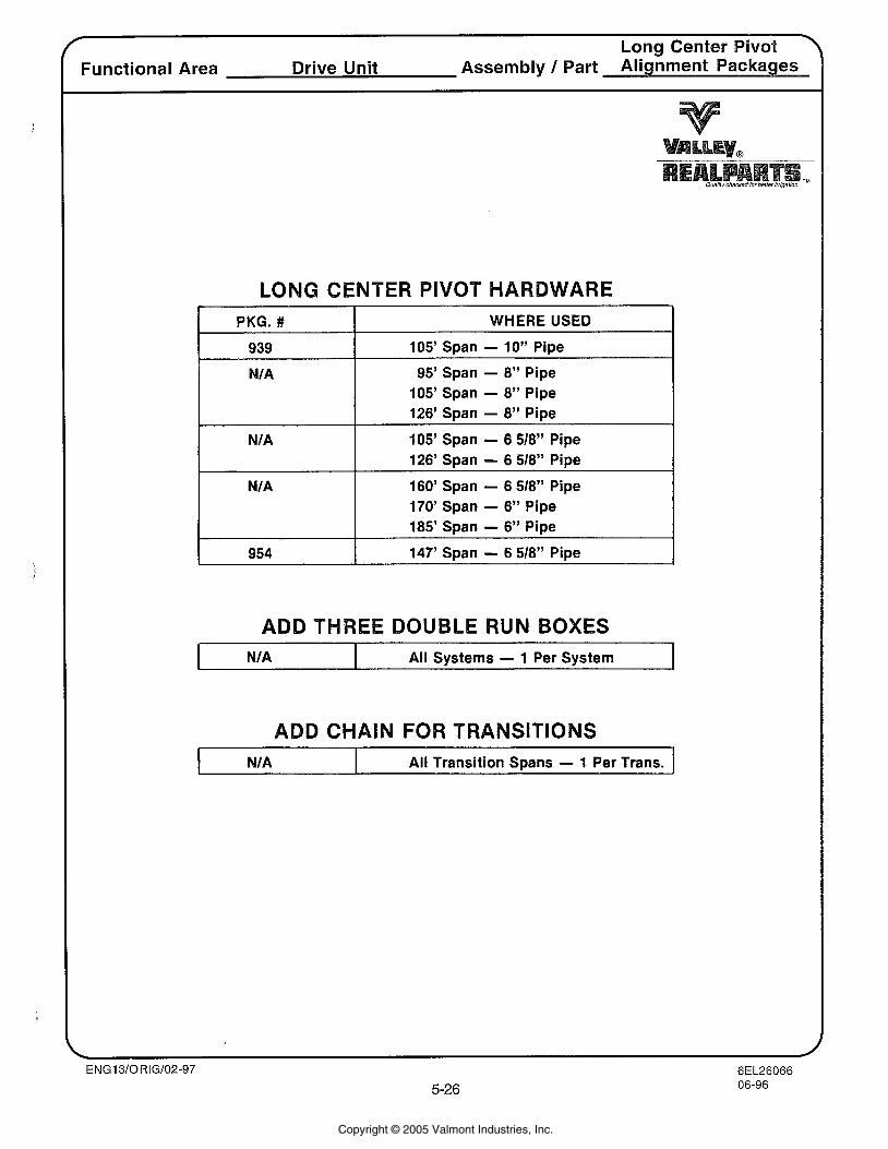
Functional Area Drive Unit Assembly I Part Alignment Packages
NTER PIVOT HARDWARE I PKG. # WHERE USED
105' Span - 10" Pipe
95' Span - 8" Pipe 105' Span - 8" Pipe 126' Span - 8" Pipe
105' Span - 6 5/8" Pipe 126' Span - 6 518" Pipe
160' Span - 6 518" Pipe 170' Span - 6" Pipe 185' Span - 6" Pipe
147' Span - 6 518" Pipe
ADD THREE DOUBL UN BOXES
I N/A All Systems - 1 Per System I
ADD CHAIN FOR TRANSITIONS
I N/A I All Transition Spans - 1 Per Trans.
Copyright © 2005 Valmont Industries, Inc.
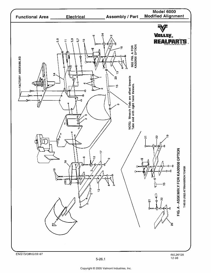
Model 6000 Functional Area Electrical Assembly / Part Modified Alignment
Copyright © 2005 Valmont Industries, Inc.
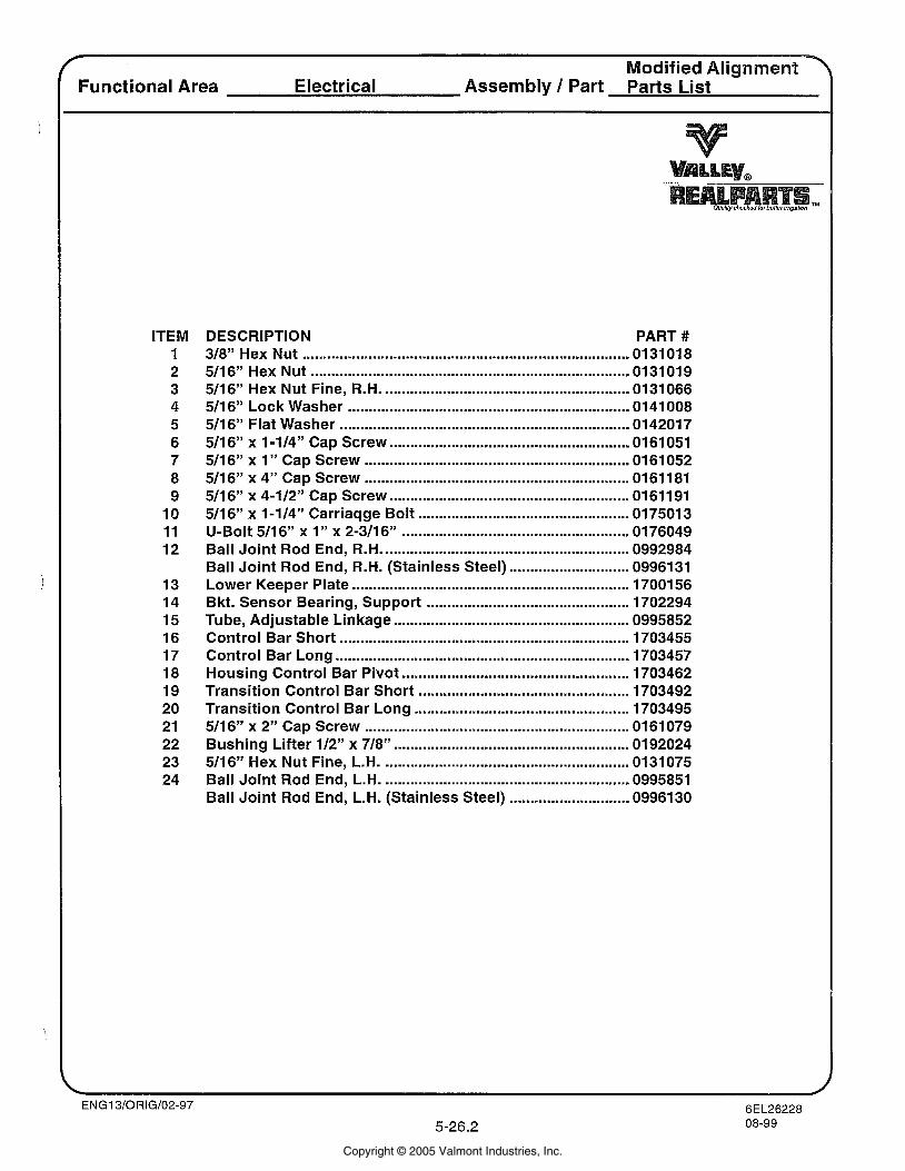
ITEM 1 2 3 4 5 6 7 8 9
10 11 12
DESCRIPTION PART # 318" Hex Nut ........................................................................ 0131 01 8 5/16" Hex Nut ........................................................................... 0131019 5/16'' Hex Nut Fine. R.H. .......................................................... 0131066 511 6" Lock Washer ................................................................ 0141 008 511 6" Flat Washer ..................................................................... 01 4201 7 5/16" x 1-114" Cap Screw ......................................................... 0161051 511 6" x 1 " Cap Screw ................................................................ 01 61 052 511 6" x 4" Cap Screw ................................................................ 01 61 181 5/16" x 4-112" Cap Screw .......................................................... 0161191 511 6" x 1-114" Carriaqge Bolt ................................................... 017501 3 U-Bolt 511 6" x 1 " x 2-311 6" ...................................................... 01 76049 Ball Joint Rod End. R.H. .......................................................... 0992984 Ball Joint Rod End. R.H. (Stainless Steel) ............................. 0996131 Lower Keeper Plate ................................................................... 17001 56 Bkt . Sensor Bearing. Support ................................................. 1702294 Tube. Adjustable Linkage ....................................................... 0995852 Control Bar Short ................................................................. 1703455 Control Bar Long ..................................................................... 1703457 Housing Control Bar Pivot ...................................................... 1703462 Transition Control Bar Short ................................................... 1703492 Transition Control Bar Long .................................................... 1703495 511 6" x 2" Cap Screw .............................................................. 0161 079 Bushing Lifter 112" x 718" ......................................................... 0192024 5/16" Hex Nut Fine. L.H. ....................................................... 0131075 Ball Joint Rod End. L.H. ........................................................... 0995851 Ball Joint Rod End. L.H. (Stainless Steel) ............................. 0996130
Functional Area Electrical Assembly / Part Parts List
ENG13/ORIG/02-97 6EL26228
5.26.2 08-99
Copyright © 2005 Valmont Industries, Inc.
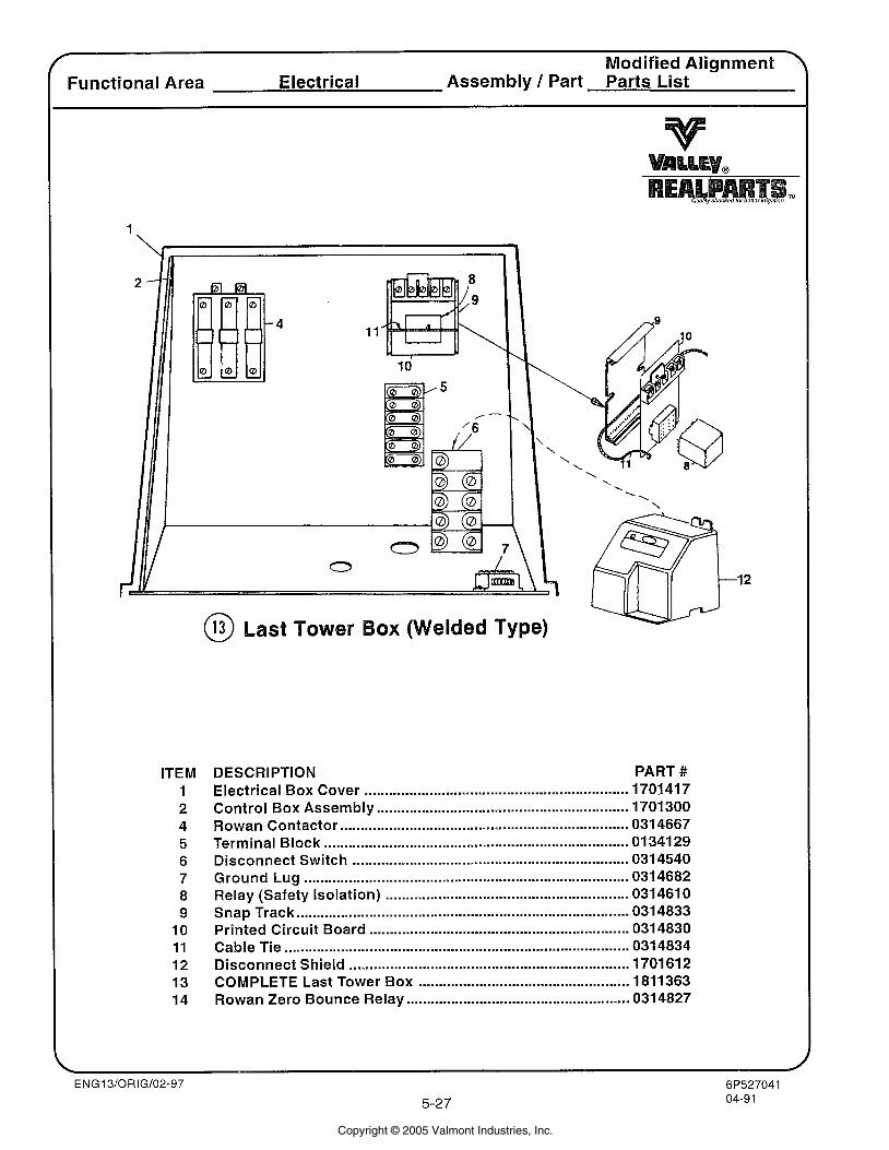
r
Modified Alignment - Functional Area Electrical Assembly / Part Parts List
ITEM 1 2 4 5 6 7 8 9
10 11 12 13 14
@ Last Tower elded Type)
DESCRIPTION PART # Electrical Box Cover ................................................................. 1701417 Control Box Assembly .............................................................. 1701300 Rowan Contactor ...................................................................... 0314667 Terminal Block .......................................................................... 0134129 Disconnect Switch .................................................................. 0314540 Ground Lug .............................................................................. 0314682 Relay (Safety Isolation) ........................................................... 031 461 0
.................................................................................. Snap Track 031 4833 Printed Circuit Board ............................................................... 0314830 Cable Tie ................................................................................... 0314834 Disconnect Shield .................................................................... 1701612 COMPLETE Last Tower Box ................................................... 1811363 Rowan Zero Bounce Relay ....................................................... 0314827
Copyright © 2005 Valmont Industries, Inc.
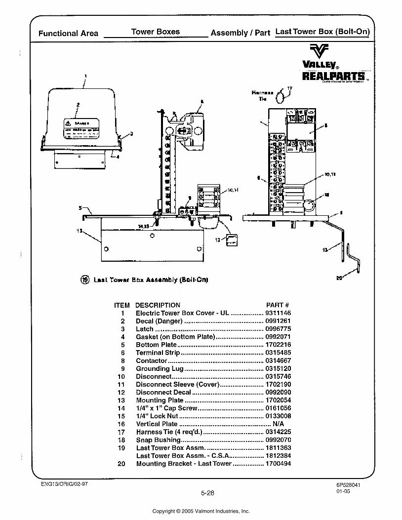
Functional Area Tower Boxes Assembly 1 Part Last Tower Box (Bolt-On)
ITEM 1 2 3 4 5 6 8 9 10 11 12 13 14 15 16 17 18 19
20
DESCRIPTION PART # - .................. Electric Tower Box Cover UL 931 1 146
........................................... Decal (Danger) 0991261 ........................................................... Latch 0996775
.......................... Gasket (on Bottom Plate) 0992071 Bottom Plate ............................................. 170221 6
............................................. Terminal Strip 0315485 .................................................... Contactor 031 4667
............................................ Grounding Lug 031 51 20 .................................................. Disconnect 0315746
........................ Disconnect Sleeve (Cover) 17021 90 Disconnect Decal ....................................... 0992090 Mounting Plate ........................................... 1702054
" ................................... 114" x 1 Cap Screw 01 61 056 .............................................. 114" Lock Nut 0133008 .................................................. Vertical Plate NIA
Harness Tie (4 req'd.) ................................. 0314225 Snap Bushing ............................................. 0992070
............................... Last Tower Box Assm. 181 1363 - ................... Last Tower Box Assm. C.S.A 1812384
- ................. Mounting Bracket Last Tower 1700494
Copyright © 2005 Valmont Industries, Inc.
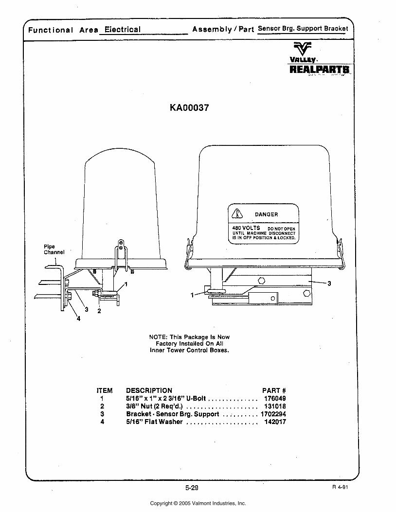
1 Zunct ional Area Electrical Assembly / Part Sensor Brg. Support Bracket
UNTIL MACHINE DISCONNECT IS IN OFF POSITION & LOCKED.
NOTE: This Package Is Now Factory Installed On All
Inner Tower Control Boxes.
ITEM DESCRIPTION PART # 1 511 6" x 1 " x 2 311 6" U-Bolt . . . . . . . . . . . . . . 176049 2 318" Nut (2 Req'd.) . . . . . . . . . . . . . . . . . . . . 13101 8 3 Bracket . Sensor Brg. Support . . ; . . . . . . . 1702294 4 5116" Flat Washer . . . . . . . . . . . . . . . . . . . . 142017
Copyright © 2005 Valmont Industries, Inc.
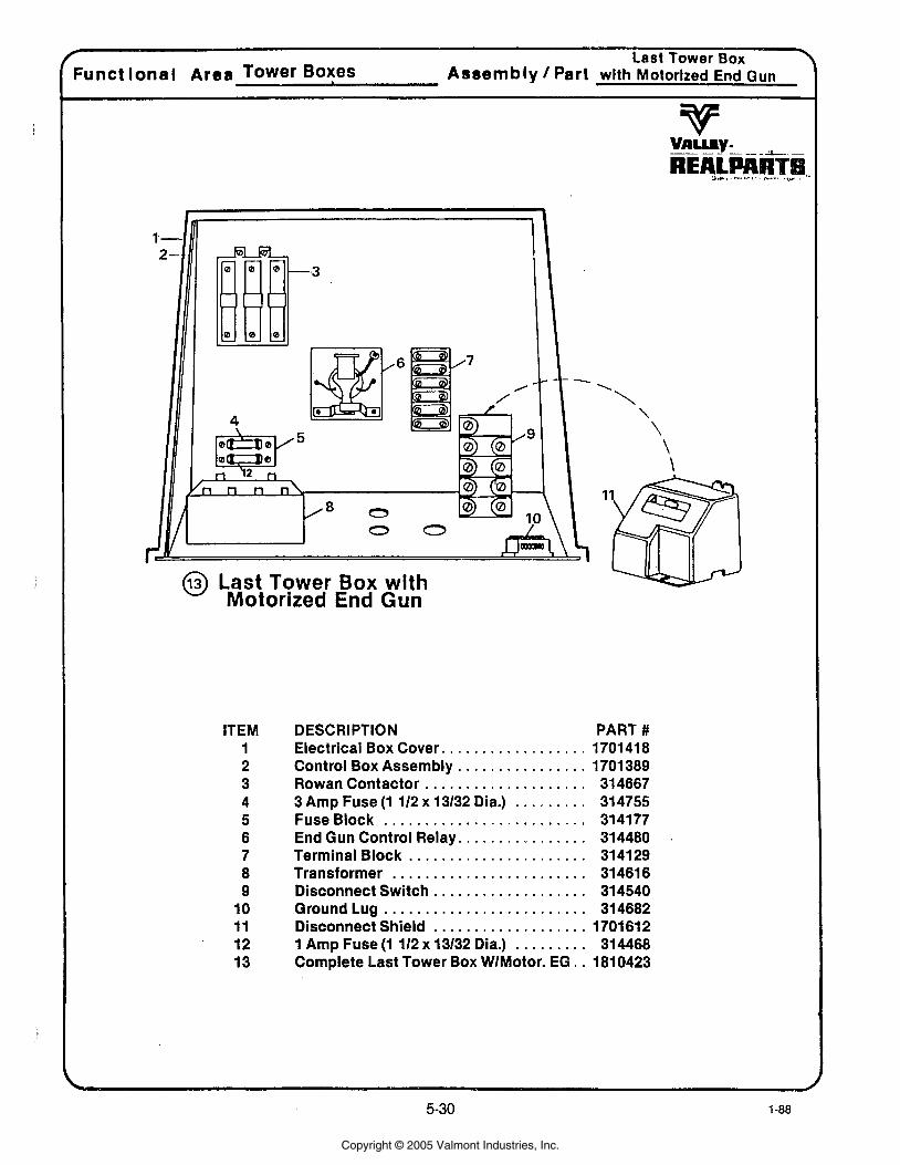
@ Last Tower Box with Motorized End Gun
ITEM 1 2 3 4 5 6 7 8 9
10 11 12 13
DESCRIPTION PART # Electrical Box Cover. . . . . . . . . . . . . . . . . . 1701 41 8 Control Box Assembly . . . . . . . . . . . . . . . . 1701 389 Rowan Contactor . . . . . . . . . . . . . . . . . . . . 314667 3 Amp Fuse (1 112 x 13132 Dia.) . . . . . . . . . 314755
. . . . . . . . . . . . . . . . . . . . . . . . . FuseBlock 314177 End Gun Control Relay. . . . . . . . . . . . . . . . 314480 . Terminal Block . . . . . . . . . . . . . . . . . . . . . . 314129 Transformer . . . . . . . . . . . . . . . . . . . . . . . . 31461 6 Disconnect Switch . . . . . . . . . . . . . . . . . . . 314540 GroundLug . . . . . . . . . . . . . . . . . . . . . . . . . 314682 Disconnect Shield . . . . . . . . . . . . . . . . . . . 1701 61 2 1 Amp Fuse (1 112 x 1 3132 Dia.) . . . . . . . . . 31 4468 Complete bast Tower Box WIMotor. EG . . 1810423
Copyright © 2005 Valmont Industries, Inc.
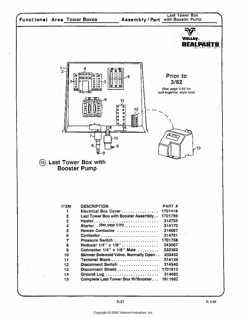
Last Tower Box \ Functional Area Tower Boxes Assembly / Part with Booster Pump
@ Last Tower Box with Booster Pump
Prior to 3/82
(See page 5-33 for bolt-together style box)
ITEM 1 2 3 4 5 6 7 8 9 10 11 12 13 14 15
DESCRIPTION . . . . . . . . . . . . . . . Electrical Box Cover.
Last Tower Box with Booster Assembly. . Heater. . . . . . . . . . . . . . . . . . . . . . . . . . . . Starter . {SFe. Pa.P.5:?41. . . . . . . . . . . . . . .
. . . . . . . . . . . . . . . . . . Rowan Contactor . . . . . . . . . . . . . . . . . . . . . . . . . Contactor
. . . . . . . . . . . . . . . . . . . Pressure Switch . . . . . . . . . . . . . . . . Reducer 114" x 118''
. . . . . . . . . Connector 114" x 118" Male Skinner Solenoid Valve, Normally Open. .
................... Terminal Block.. . . . . . . . . . . . . . . . . . Disconnect Switch . . . . . . . . . . . . . . . . . Disconnect Shield.
. . . . . . . . . . . . . . . . . . . . . . . Ground Lug . . . Complete Last Tower Box WIBooster
PART # 1701 41 8 1701 759 31 4753 314170 31 4667 31 4751
1 701 758 243007 232362 232452 31 41 29 31 4540 1701 61 2 31 4682 I81 1602
Copyright © 2005 Valmont Industries, Inc.
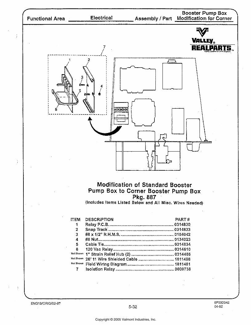
Booster Pump Box 7 Functional Area Electrical Assembly 1 Part Modification for Corner
Modification of Standard Booster Pump Box to Corner Boaster Pump Box
Pkg. 887 (Includes Items Listed Below and All Misc; Wires Needed)
ITEM DESCRlPTlON PART # ....................................................... I Relay P.C.B 0314830. ...................................................... 2 Snap Track 0314833
.............................................. 3 #8 x 112" R.H.M.S. 0164042 .................................................................. 4 #8 Nut 0134023
............................................................. 5 Cable Tie 0314834 ................................................... 6 120 Vac Relay 0314610
................................. Notshown I" Strain Relief Hub (2) 0314466 .............................. NotShwn 26' I 1 wire Shielded Cable 1811498
......................................... Field Wiring Diagram 1811481 ................................................... 7 Isolation Relay 0000738
Copyright © 2005 Valmont Industries, Inc.
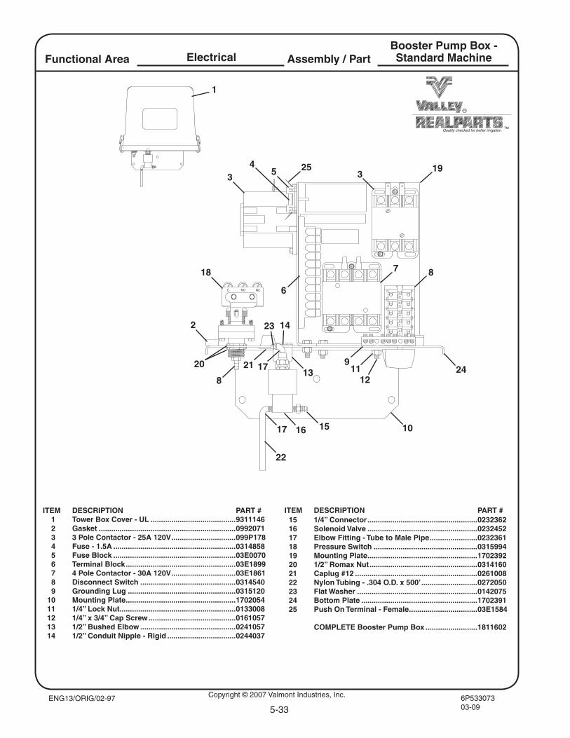
Copyright © 2007 Valmont Industries, Inc. 6P53307303-09
Assembly / PartFunctional Area Electrical
5-33
Quality checked for better irrigation
ITEM DESCRIPTION PART # 1 Tower Box Cover - UL .........................................9311146 2 Gasket ..................................................................0992071 3 3 Pole Contactor - 25A 120V ...............................099P178 4 Fuse - 1.5A ...........................................................0314858 5 Fuse Block ...........................................................03E0070 6 Terminal Block .....................................................03E1899 7 4 Pole Contactor - 30A 120V ...............................03E1861 8 Disconnect Switch ..............................................0314540 9 Grounding Lug ....................................................0315120 10 Mounting Plate .....................................................1702054 11 1/4” Lock Nut ........................................................0133008 12 1/4” x 3/4” Cap Screw ..........................................0161057 13 1/2” Bushed Elbow ..............................................0241057 14 1/2” Conduit Nipple - Rigid .................................0244037
Booster Pump Box -Standard Machine
ENG13/ORIG/02-97
3
6
19
7
54
18
8
15
20 21
14
17
17
22
16
13
23
10
1211
15 1/4” Connector .....................................................0232362 16 Solenoid Valve .....................................................0232452 17 Elbow Fitting - Tube to Male Pipe .......................0232361 18 Pressure Switch ..................................................0315994 19 Mounting Plate .....................................................1702392 20 1/2” Romax Nut ....................................................0314160 21 Caplug #12 ...........................................................0261008 22 Nylon Tubing - .304 O.D. x 500’ ...........................0272050 23 Flat Washer ..........................................................0142075 24 Bottom Plate ........................................................1702391 25 Push On Terminal - Female .................................03E1584
COMPLETE Booster Pump Box .........................1811602
249
8
2
3
1
ITEM DESCRIPTION PART #
25
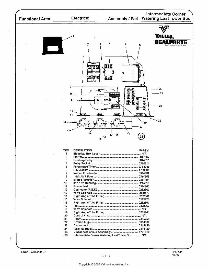
lntermediate Corner Functional Area Electrical Assembly / Part Watering Last Tower Box
ITEM 1 2 3 4 5 6 7 8 9 10 11 12 13 14 15 16 17 18 19 20 21 22 23 24 25 26
DESCRIPTION PART # Electrical Box Cover ....................................................... NIA Starter ......................................................................... 031 4667 Latching Relay ........................................................... 0314815 Relay Socket ............................................................... 0314814 PercentageTimer ........................................................ 03E2035 P.T. Bracket ................................................................. 1750504 In-Line Fuseholder ........................... .. ...................... 0314882 1-112 AMP Fuse ........................................................... 0314858 Bridge Rectifier .......................................................... 0314894 318" 112" Bushing ...................................................... 0244010 Roman Nut .................................................................. 0314160 Connector (R.E.F.) ...................................................... 0232367 Valve Solenoid ............................................................ 0232170 Right AngleTube Fitting ............................................ 0232361 Valve Solenoid ............................................................ 0232170 Right AngleTube Fitting ........................................ 0232361 Tee ................................................................................ 0232367 Valve Solenoid ................................................................ N/A Right AngleTube Fitting ........................................... 0232361 Control Plate .................................................................... NIA Relay ............................................................................ 031 5559 Ground Lug ................................................................. 0314682 Disconnect ................................................................ 0314540 Terminal Block ............................................................ 0314129 Disconnect Shield Assembly .................................... 1701612 Intermediate Corner Watering LastTower Box ............ NIA
Copyright © 2005 Valmont Industries, Inc.
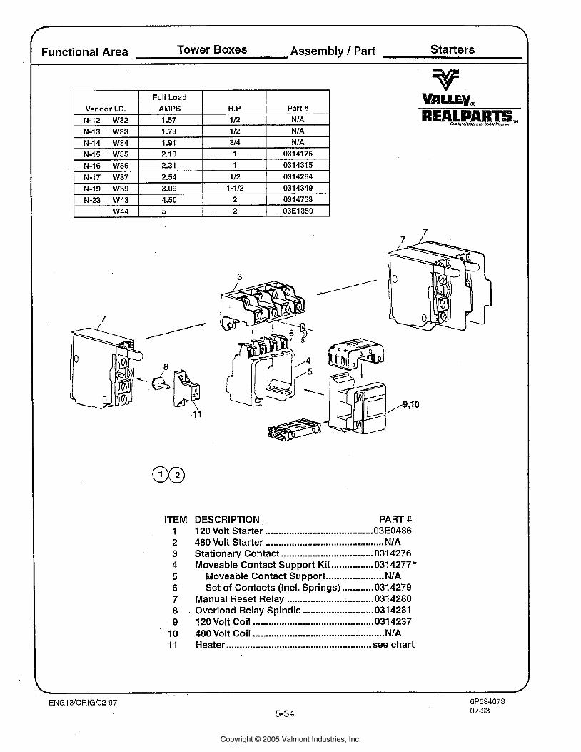
Functional Area Tower Boxes Assembly / Part Starters
Full Load I Vendor I.D. AMPS H.P. Part #
N-12 W32 1.57 1 I2 NIA
N-13 W33 1.73 1 I2 NIA
ITEM 1 2 3 4 5 6 7 8 9
10 11
DESCRIPTION. PART # 120 Volt Starter ......................................... 03E0486 480 Volt Starter ............................................. NIA Stationary Contact ................................... 031 4276 Moveable Contact Support Kit ................ 031 4277 *
Moveable Contact Support ...................... NIA Set of Contacts (Incl. Springs) ............ 031 4279
Manual Reset Relay ................................. 031 4280 Overload Relay Spindle ........................... 031 4281 120 Volt Coil .............................................. 031 4237 480 Volt Coil .................................................. NIA Heater .................................................... see chart
Copyright © 2005 Valmont Industries, Inc.
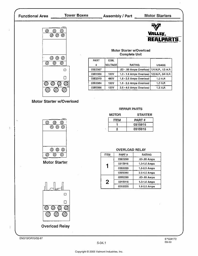
Functional Area Tower Boxes Assembly I Part Motor Starters
Motor Starter wIOverload Complete Unit
1 03E2319 1 480V I 1.6 - 2.5 Amps Overload I 1.0 H.P. I
PART
#
03E0367
03E0366
Motor Starter wIOverload
COIL
VOLTAGE
120V
03E0384
03E0386
REPAIR PARTS
Motor Starter
RATING
.63 - .99 Amps Overload
1.0 - 1.6 Amps Overload
120V
120V
Overload Relay
USAGE
114 H.P., 113 H.P.
112 H.P., 314 H.P.
MOTOR STARTER
I ITEM I PART #
1.6 - 2.5 Amps Overload
2.5 - 4.0 Amps Overload
OVERLOAD RELAY
-- -
1.0 H.P.
1.5 H.P.
ITEM
1 03E0329 1 1.6-2.5 Amps 2
PART #
03E0299
0315916
03.0329
03E0385
03E0299 I
0315916 1 1 .O-1.6 Amps
RATING
53-.99 Amps
1 .O-1.6 Amps
1.6-2.5 Amps
2.5-4.0 Amps
.63-.99 Amps
Copyright © 2005 Valmont Industries, Inc.
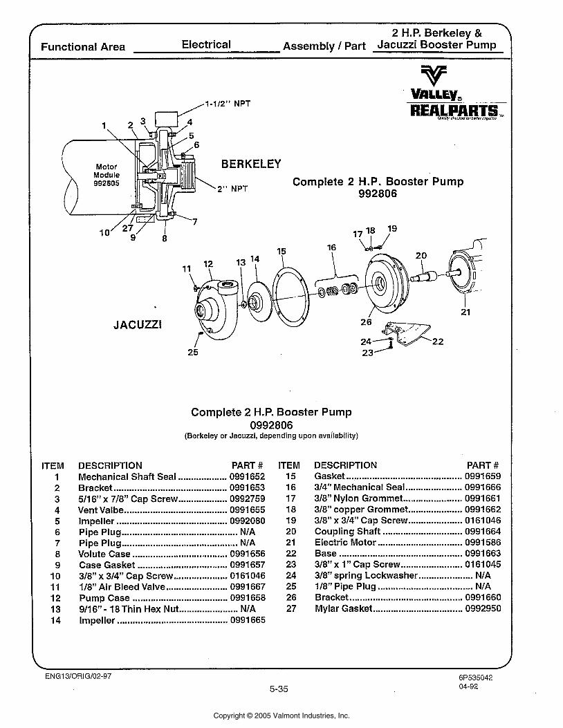
2 H.P. Berkeley & Functional Area Electrical Assembly / Part Jacuzzi Booster Pump
d l - 1 1 2 " NPT
ITEM 1 2 3 4 5 6 7 8 9
10 11 12 13 14
BERKELEY
,2" NPT Complete 2 H.P. Booster Pump
992806
1
21
JACUZZI
Complete 2 H.P. Booster Pump 0992806
(Berkeley or Jacuzzi, depending upon availability)
DESCRIPTION PART # Mechanical Shaft Seal ................... 0991 652 Bracket ............................................ 0991 653 511 6" x 718" Cap Screw ................... 0992759 Vent Valbe ........................................ 0991 655 Impeller ........................................... 0992080
............................................. Pipe Plug NIA Pipe Plug ............................................. NIA Volute Case ..................................... 0991 656 Case Gasket ................................... 0991 657 318" x 314" Cap Screw ..................... 01 61 046 118" Air Bleed Valve ........................ 0991 667 Pump Case ..................................... 0991 658
....................... 9116" - 18 Thin Hex Nut NIA Impeller ........................................... 0991 665
ITEM 15 16 17 18 19 20 21 22 23 24 25 26 27
DESCRIPTION PART # Gasket .............................................. 0991 659 314" Mechanical Seal ...................... 0991 666 318" Nylon Grommet ....................... 0991661 318" copper Grommet ..................... 0991 662 318" x 314" Cap Screw ..................... 01 61 046 Coupling Shaft ............................... 0991664 Electric Motor ................................. 0991 586 Base ................................................ 0991 663 318" x 1 " Cap Screw ........................ 01 61 045 318" spring Lockwasher ..................... NIA 118" Pipe Plug ..................................... NIA Bracket ........................................... 0991 660 Mylar Gasket ................................... 0992950
Copyright © 2005 Valmont Industries, Inc.
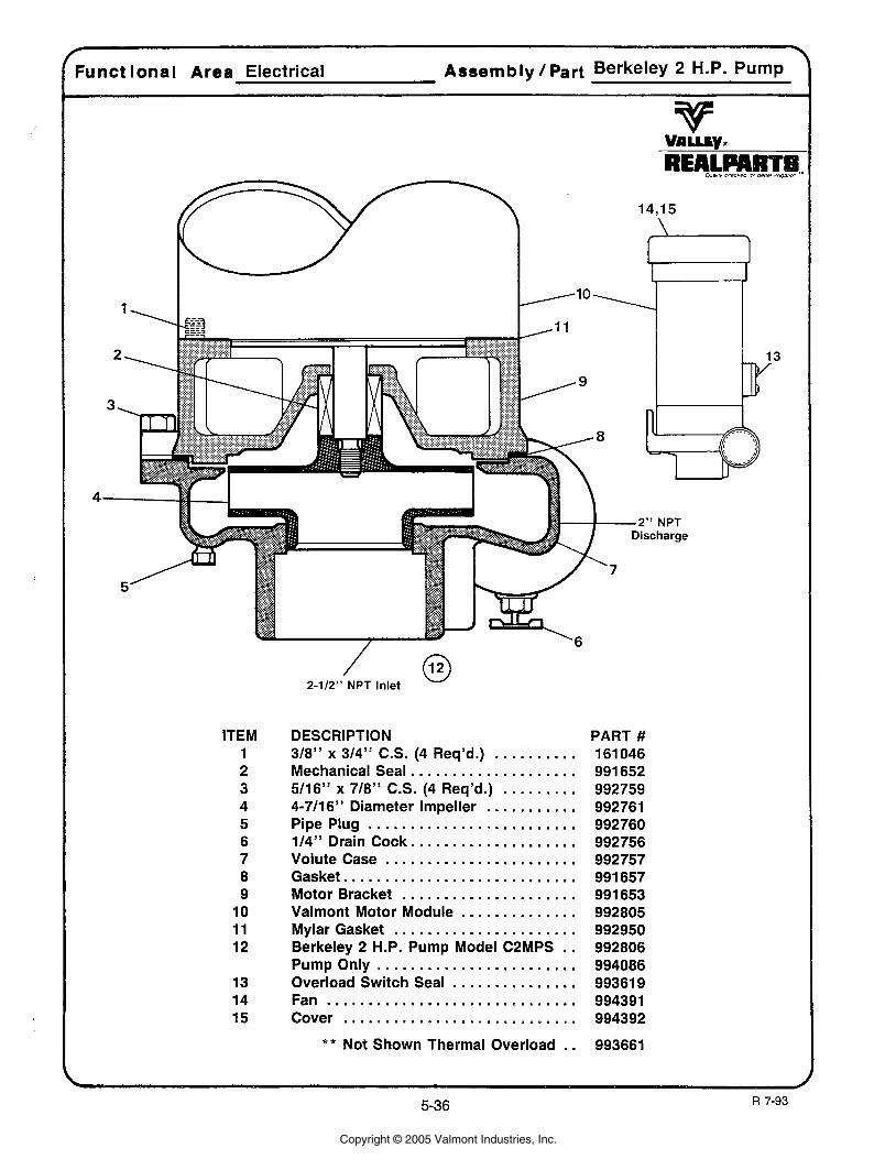
2-112" NPT Inlet
ITEM 1 2 3 4 5 6 7 8 9
10 11 12
13 14 15
DESCRIPTION PART # . . . . . . . . . . 318" x 314" C.S. (4 Req'd.) 161046
. . . . . . . . . . . . . . . . . . . . Mechanical Seal 991 652 ......... 511 6" x 718" C.S. (4 Req'd.) 992759
. . . . . . . . . . . 4-711 6" Diameter Impeller 992761 ......................... Pipe Plug 992760
.................... 114" Drain Cock 992756 ....................... Volute Case 992757
Gasket ............................ 991657 Motor Bracket . . . . . . . . . . . . . . . . . . . . . 991 653
.............. Valmont Motor Module 992805 ...................... Mylar Gasket 992950
Berkeley 2 H.P. Pump Model C2MPS . . 992806 Pump Only ........................ 994086
............... Overload Switch Seal 99361 9 Fan .............................. 994391 Cover ........................... 994392
* * Not Shown Thermal Overload . . 993661
Copyright © 2005 Valmont Industries, Inc.
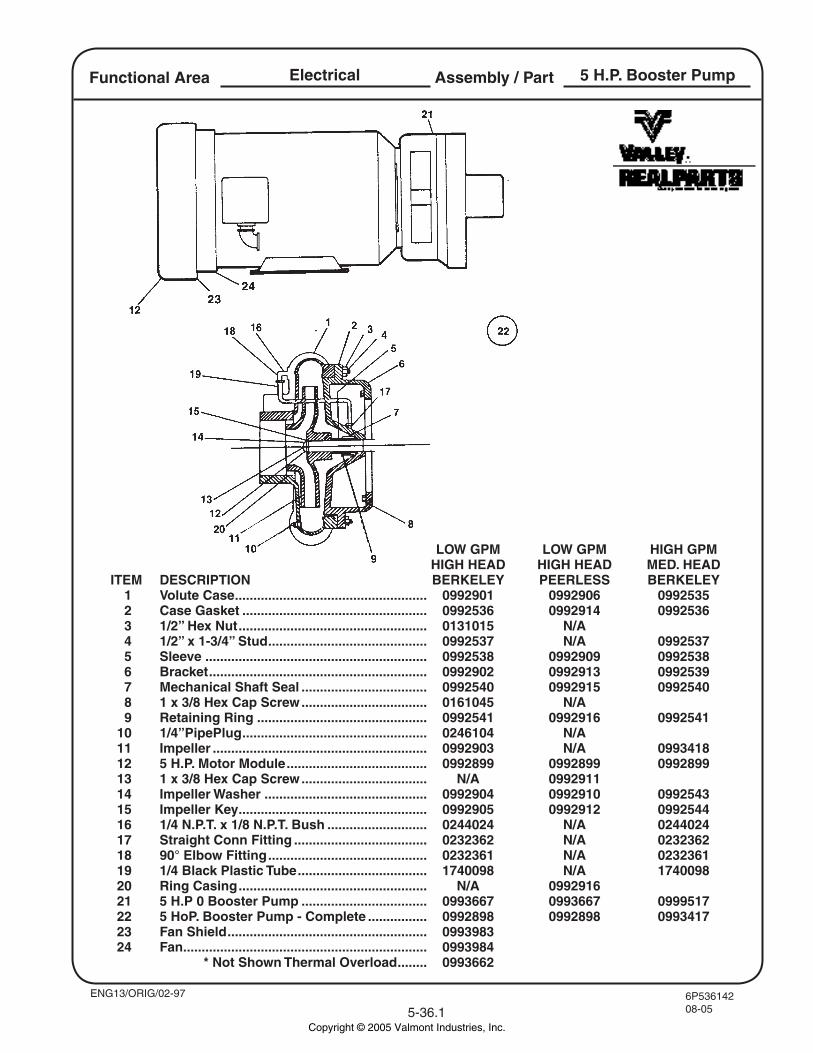
6P53614208-055-36.1
Assembly / PartElectricalFunctional Area 5 H.P. Booster Pump
ENG13/ORIG/02-97
LOW GPM LOW GPM HIGH GPM HIGH HEAD HIGH HEAD MED. HEAD ITEM DESCRIPTION BERKELEY PEERLESS BERKELEY 1 Volute Case .................................................... 0992901 0992906 0992535 2 Case Gasket .................................................. 0992536 0992914 0992536 3 1/2” Hex Nut ................................................... 0131015 N/A 4 1/2” x 1-3/4” Stud ........................................... 0992537 N/A 0992537 5 Sleeve ............................................................ 0992538 0992909 0992538 6 Bracket ........................................................... 0992902 0992913 0992539 7 Mechanical Shaft Seal .................................. 0992540 0992915 0992540 8 1 x 3/8 Hex Cap Screw .................................. 0161045 N/A 9 Retaining Ring .............................................. 0992541 0992916 0992541 10 1/4”PipePlug .................................................. 0246104 N/A 11 Impeller .......................................................... 0992903 N/A 0993418 12 5 H.P. Motor Module ...................................... 0992899 0992899 0992899 13 1 x 3/8 Hex Cap Screw .................................. N/A 0992911 14 Impeller Washer ............................................ 0992904 0992910 0992543 15 Impeller Key ................................................... 0992905 0992912 0992544 16 1/4 N.P.T. x 1/8 N.P.T. Bush ........................... 0244024 N/A 0244024 17 Straight Conn Fitting .................................... 0232362 N/A 0232362 18 90° Elbow Fitting ........................................... 0232361 N/A 0232361 19 1/4 Black Plastic Tube ................................... 1740098 N/A 1740098 20 Ring Casing ................................................... N/A 0992916 21 5 H.P 0 Booster Pump .................................. 0993667 0993667 0999517 22 5 HoP. Booster Pump - Complete ................ 0992898 0992898 0993417 23 Fan Shield ...................................................... 0993983 24 Fan .................................................................. 0993984
* Not Shown Thermal Overload ........ 0993662
Copyright © 2005 Valmont Industries, Inc.
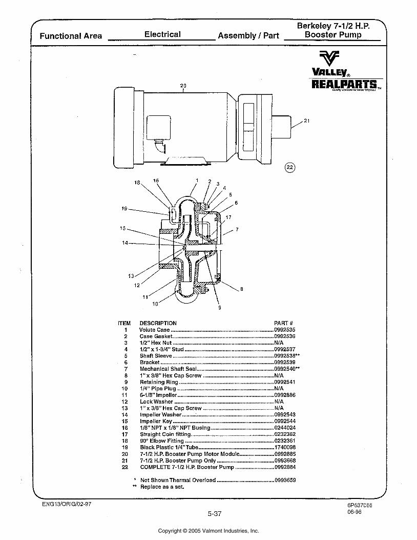
Berkeley 7-112 H.P. 7
Functional Area Electrical Assembly I Part ~oosfer Pump
ITEM DESCRIPTION PART # Volute Case .................................................................... 0992535 Case Gasket ................................................................... 0992536
................................................................... 112" Hex Nut NIA ........................................................... 112" x 1-314" Stud 0992537
Shaft Sleeve ................................................................... 0992538** Bracket ........................................................................... 0992539 Mechanical Shaft Seal ................................................... 0992540** 1" x 318" Hex Cap Screw ............................................... NIA Retaining Ring ............................................................... 0992541 114" Pipe Plug ................................................................ NIA 6-118" Impeller ................................................................ 0992886 Lock Washer .................................................................. NIA 1" x 318" Hex Cap Screw ............................................... NIA
............................................................. Impeller Washer 0992543 ................................................................... Impeller Key 0992544
.......................................... 118" NPT x 118" NPT Busing 0244024 Straight Coin fitting ....................................................... 0232362 90" Elbow Fitting ........................................................... 0232361 Black Plastic 114"Tube ................................................. 1740098 7-112 H.P. Booster Pump Motor Module ....................... 0992885 7-112 H.P. Booster Pump Only ..................... ; ................ 0993668 COMPLETE 7-112 H.P. Booster Pump .......................... 0992884
* Not Shown Thermal Overload ...................................... 0993659 ** Replace as a set.
Copyright © 2005 Valmont Industries, Inc.
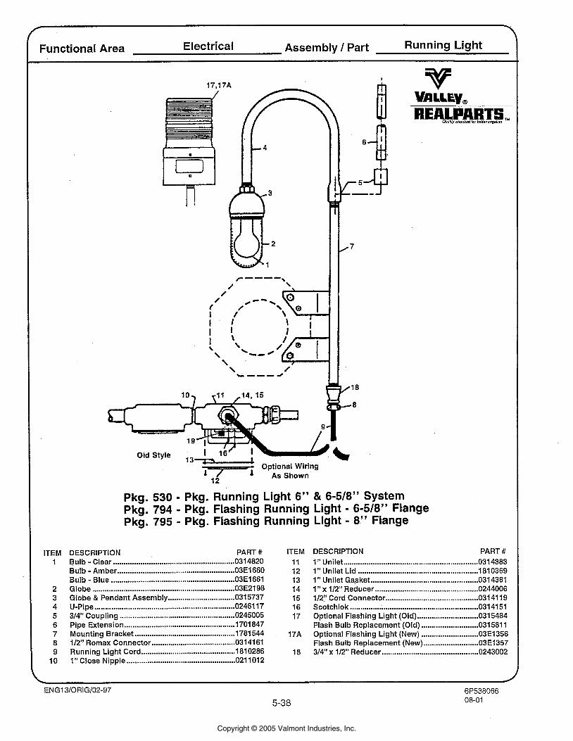
Functional Area Electrical Assembly 1 Part Running Light
ITEM 1
13- Optional Wiring '
Pkg. 530 - Pkg. Running Light 6" & 6-518" System Pkg. 794 - Pkg. Flashing Running Light - 6-518" Flange Pkg. 795 - Pkg. Flashing Running Light - 8" Flange
DESCRIPTION PART # Bulb - Clear .......................................................... 0 3 4820 Bulb - Amber ....................................................... 0 3 6 6 0 Bulb - Blue .......................................................... 0 1 6 6 1 Globe .................................................................... 0 3 2 9 8 Globe & Pendant Assembly ................................ 035737 U-Pipe .................................................................. 0246117 314" Coupling ....................................................... 0245005 Pipe Extension ..................................................... 1701847 Mounting Bracket ................................................ 1781544 112" Romax Connector ........................................ 0314161 Running Light Cord ............................................. 1810286 I" Close Nipple .................................................... 021 1012
ITEM 11 12 13 14 15 16 17
DESCRIPTION PART # ................................................................ 1" Unilet 0314383
.......................... ........................... 1" Unilet Lid .. 810369 ................................................... 1 " Unilet Gasket 0314381 ................................................. I" x 112" Reducer 0244006
............................................ 1/21' Cord Connector 031 41 19 Scotchlok ............................................................. 031 41 51
............................. Optional Flashing Light (Old) 0315484 ........................... Flash Bulb Replacement (Old) 031581 1 ........................... Optional Flashing Light (New) 03E1356 .......................... Flash Bulb Replacement (New) 03E1357
.............................................. 314" x 112" Reducer 0243002
Copyright © 2005 Valmont Industries, Inc.
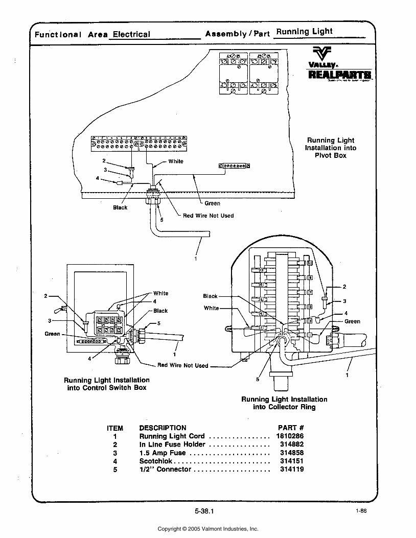
(Funct lonal Area Electrical Assembly /Part Running Light I
\ Red Wire Not Used I l 5
Running Light Installation into
Pivot Box
Running Light Installation into Control Switch Box
Running Light Installation into Collector Ring
ITEM DESCRIPTION PART # ................ 1 Running Light Cord 1810286 ................ 2 In Line Fuse Holder 314882
..................... 3 1.5 Amp Fuse 314858 ......................... 4 Scotchlok 314151
.................... 5 112" Connector 3141 19
Copyright © 2005 Valmont Industries, Inc.
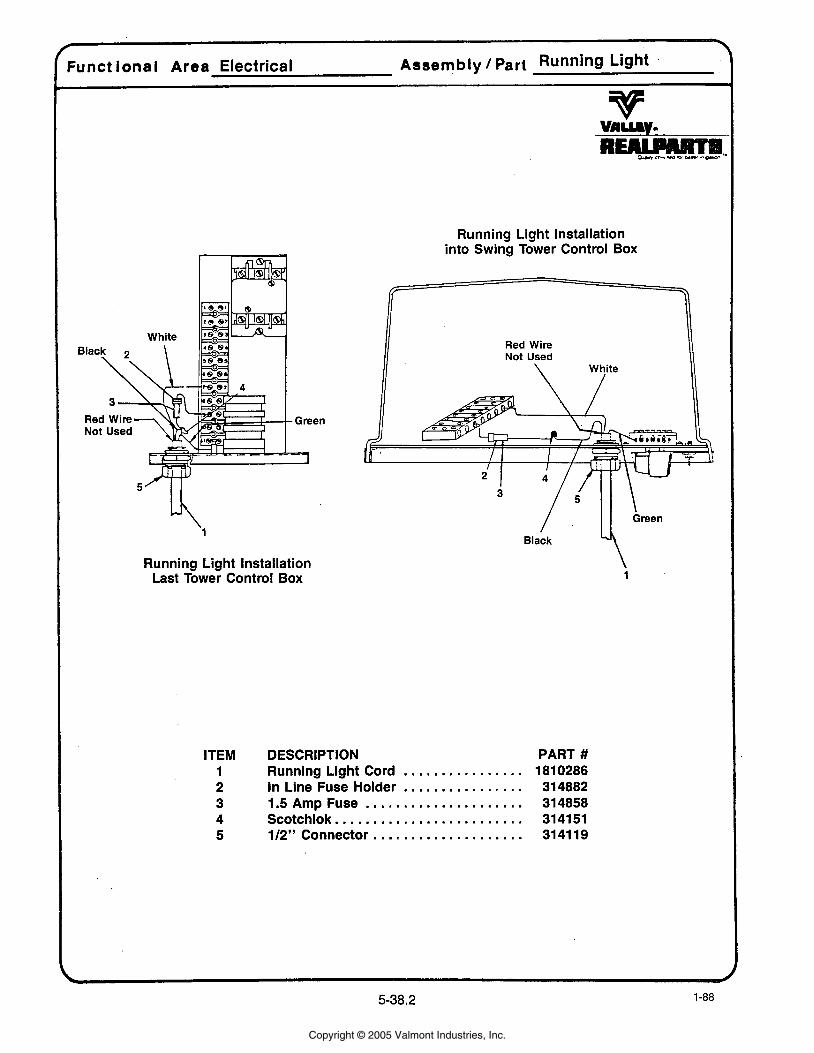
Funct ional Area Electrical Assembly /Part Running Light
Running Light Installation Last Tower Control Box
Running Light Installation into Swing Tower Control Box
Red Wire
ITEM DESCRIPTION PART # ................ 1 Running Light Cord 1810286 ................ 2 In Line Fuse Holder 314882
..................... 3 1.5 Amp Fuse 314858 ......................... 4 Scotchlok 314151
5 112" Connector .................... 31 41 19
Copyright © 2005 Valmont Industries, Inc.
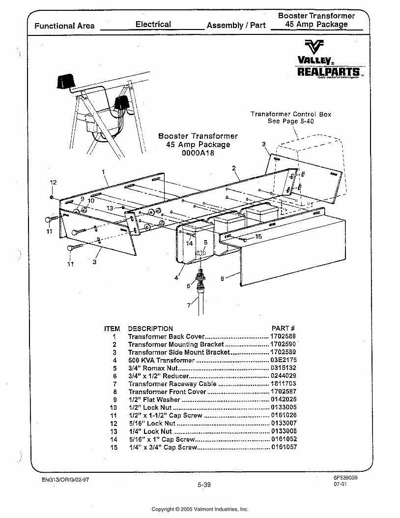
4
Booster Transformer Functional Area Electrical Assembly 1 Part 45 Amp Package
ITEM I 2 3 4 5 6 7 8 9
10 I I 12 13 14 15
DESCRIPTION PART # Transformer Back Cover .................................. 1702588 Transformer Mounting Bracket ........................ 1702590
..................... Transformer Side Mount Bracket 1702589 500 KVA Transformer ...................................... 03E2175 314" Romax Nut ................ .. ....... '...;....... ............ 0315132 314" x 112" Reducer ........................................... 0244029 Transformer Racewzy. Cable ............................ 'I 811703 Transformer Front Cover .................................. 1702587 112" Flat Washer .................... .. ..................... 0;142025 112" ~ o c k Nut ..................................................... 0133005 112" x 1-112" Cap Screw .................................... 0161026 5116" Lock Nut .................................................. 0133007 114" Lock Nut ..................................................... 0133008 5116" x 1" Cap Screw ...................................... 0161052
...................................... 114" x 314" Cap Screw 0161057
Copyright © 2005 Valmont Industries, Inc.
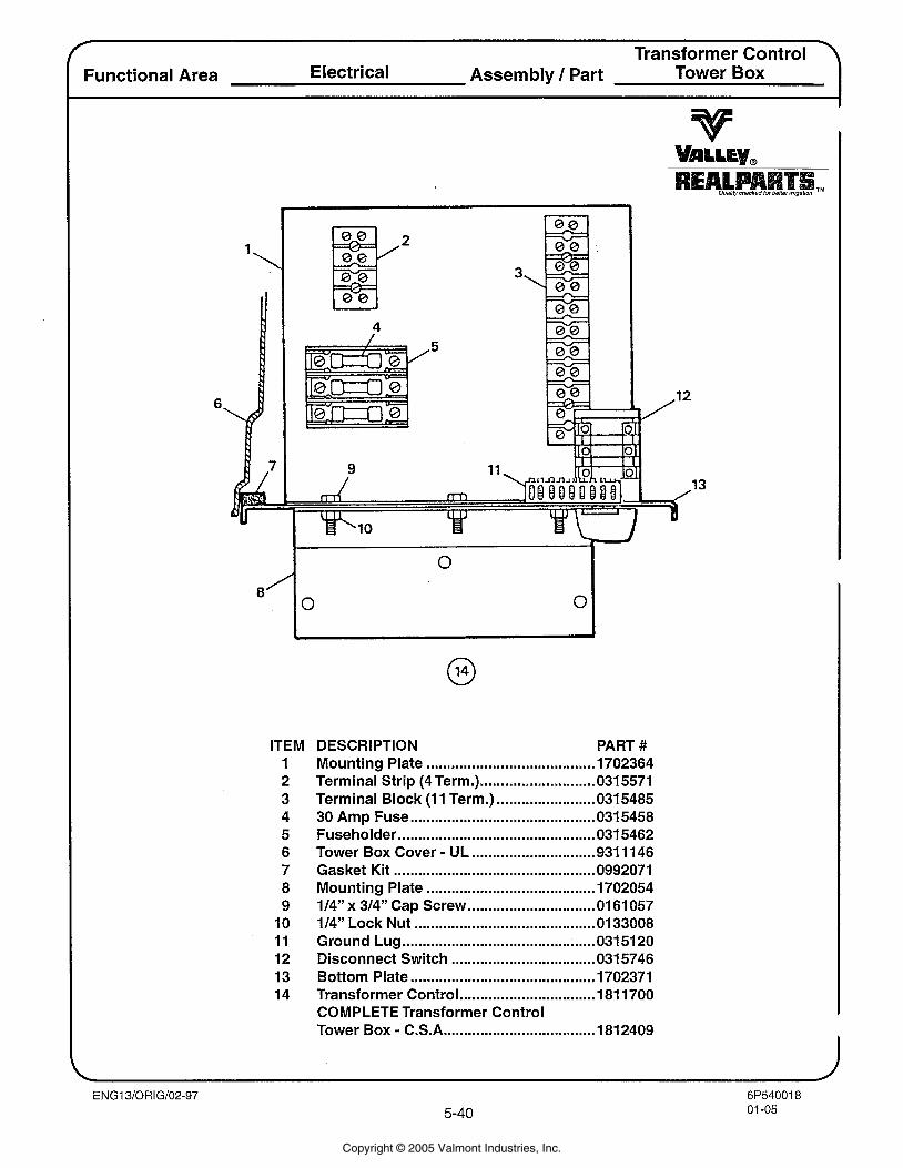
I Transformer Control \
Functional Area Electrical Assembly / Part Tower Box I
ITEM DESCRIPTION PART # 1 Mounting Plate ......................................... 1702364 2 Terminal Strip (4 Term.) ............................ 0315571 3 Terminal Block (1 1 Term.) ........................ 0315485 4 30 Amp Fuse ............................................. 031 5458 5 Fuseholder ............................................... 031 5462 6 Tower Box Cover - UL .............................. 931 11 46 7 Gasket Kit ................................................ 0992071 8 Mounting Plate ......................................... 1702054 9 114" x 314" Cap Screw ............................... 01 61 057
10 114" Lock Nut ............................................ 0133008 1 1 Ground Lug ........................................ 031 51 20 12 Disconnect Switch ................................... 031 5746 13 Bottom Plate ............................................ 1702371 14 Transformer Control ................................. 181 1700
COMPLETE Transformer Control Tower Box - C.S.A .................................... 181 2409
Copyright © 2005 Valmont Industries, Inc.
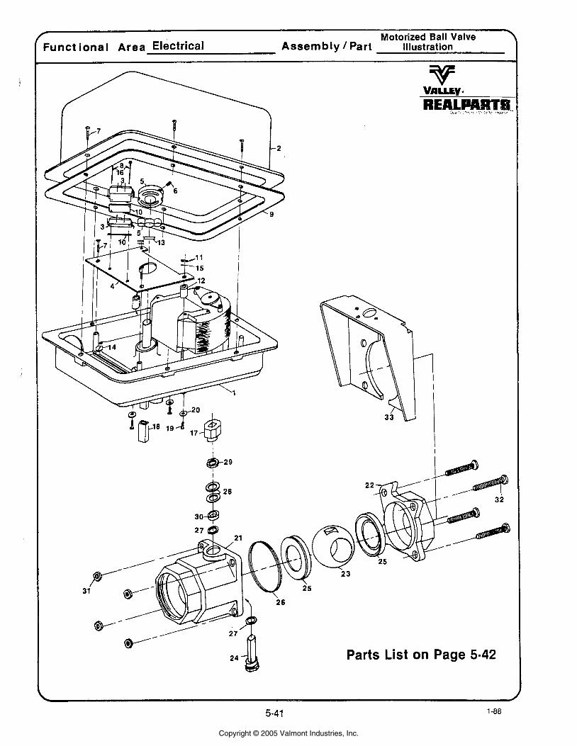
fl
Motorized Ball Valve 7 Funct ional Area Electrical Assembly Part Mustration
Parts List on Page 5-42
Copyright © 2005 Valmont Industries, Inc.
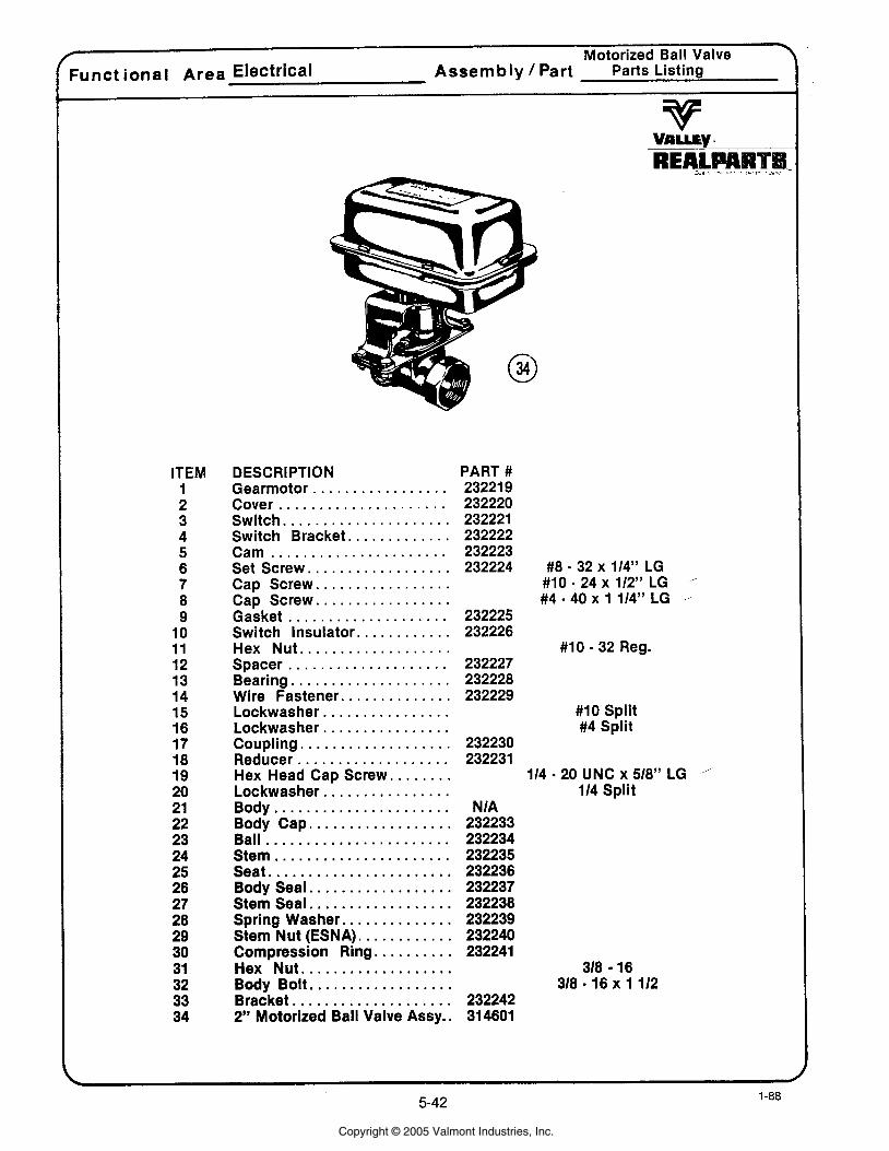
r Motorized Ball Valve F u n c t i o n a l Area Electrical A s s e m b l y / Part Parts Listing
REAL Ad . . -* I >a
ITEM 1 2 3 4 5 6 7 8 9
10 11 12 13 14 15 16 17 18 19 20 21 22 23 24 25 26 27 28 29 30 31 32 33 34
DESCRIPTION . . . . . . . . . . . . . . . . . Gearmotor
Cover . . . . . . . . . . . . . . . . . . . . . . . . . . . . . . . . . . . . . . . . . . Switch
. . . . . . . . . . . . . Switch Bracket Cam . . . . . . . . . . . . . . . . . . . . . .
. . . . . . . . . . . . . . . . . . Set Screw . . . . . . . . . . . . . . . . . Cap Screw . . . . . . . . . . . . . . . . . Cap Screw
Gasket . . . . . . . . . . . . . . . . . . . . . . . . . . . . . . . . Switch Insulator
. . . . . . . . . . . . . . . . . . . Hex Nut . . . . . . . . . . . . . . . . . . . . Spacer
Bearing . . . . . . . . . . . . . . . . . . . . . . . . . . . . . . . . . . Wire Fastener
. . . . . . . . . . . . . . . . Lockwasher
. . . . . . . . . . . . . . . . Lockwasher . . . . . . . . . . . . . . . . . . . Coupling . . . . . . . . . . . . . . . . . . . Reducer
PART # 23221 9 232220 232221 232222 232223 232224
232225 232226
232227 232228 232229
232230 232231
#10 . 32 Reg .
#10 Split #4 Split
Hex Head Cap Screw . . . . . . . . . . . . . . . . . . . . . . . . Lockwasher
Body . . . . . . . . . . . . . . . . . . . . . . Body Cap . . . . . . . . . . . . . . . . . . Ball . . . . . . . . . . . . . . . . . . . . . . . Stem . . . . . . . . . . . . . . . . . . . . . . Seat . . . . . . . . . . . . . . . . . . . . . . .
. . . . . . . . . . . . . . . . . . Body Seal
. . . . . . . . . . . . . . . . . . Stem Seal . . . . . . . . . . . . . . Spring Washer
. . . . . . . . . . . . Stem Nut (ESNA) . . . . . . . . . . Compression Ring
Hex Nut . . . . . . . . . . . . . . . . . . . . . . . . . . . . . . . . . . . . . Body Bolt
. . . . . . . . . . . . . . . . . . . . Bracket 2" Motorized Ball Valve Assy ..
114 - 2 0 UNC x 518" LG . 114 Split
N IA 232233 232234 232235 232236 232237 232238 232239 232240 232241
318 16 318 . 16 x 1112
232242 31 4601
Copyright © 2005 Valmont Industries, Inc.
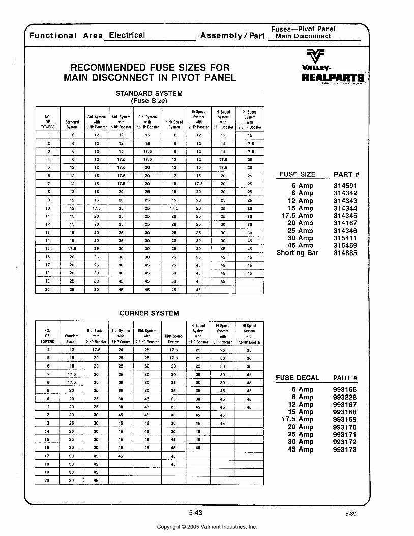
7
Fuses-Pivot Panel 7
Functional A r e a Electrical ,Assembly / Part Main Disconnect
RECOMMENDED FUSE SIZES FOR MAIN DISCONNECT IN PIVOT PANEL
STANDARD SYSTEM (Fuse Size)
Hi Speed Hi Speed Hi Speed NO. Std. System Std. System Std. System System System System OF Standard with with with High Speed with with with
TOWERS System 2 HP Booster 5 HP Booster 7.5 HP Booster System 2 HP Booster 5 HP Booster 7.5 HP Booster
1 6 12 12 15 6 12 12 15
CORNER SYSTEM
FUSE SIZE
6 Amp 8 Amp
12 Amp 15 Amp
17.5 Amp 20 Amp 25 Amp 30 Amp 45 Amp
Shorting Bar
NO. OF
TOWERS
4
5
PART #
314591 31 4342 31 4343 31 4344 31 4345 31 41 67 31 4346 31 541 1 31 5459 31 4885
FUSE DECAL PART #
Standard System
12
15
6 Amp 8 Amp
12 Amp 15 Amp
17.5 Amp 20 Amp 25 Amp 30 Amp 45 Amp
Std. System with
2 HP Booster
17.5
20
Std. System with
5 HP Comer
20
25
Std. System with
7.5 HP Booster
25
25
High Speed System
17.5
17.5
Hi Speed System
with 2 HP Booster
25
25
Hi Speed System
with 5 HP Comer
25
30
Hi Speed System
with 7.5 HP Booster
30
30
Copyright © 2005 Valmont Industries, Inc.
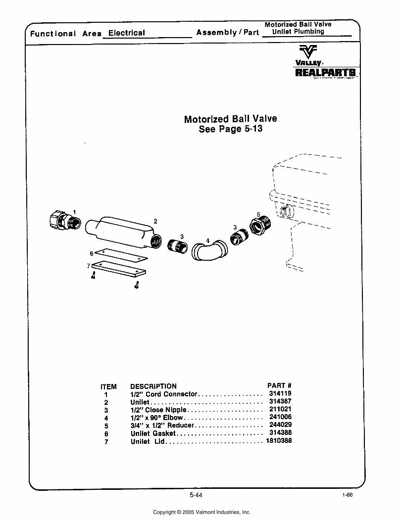
Motorized Ball Valve I
h n c t ional Area Electrical Assembly / Part Unllet Plumbing
Motorized Ball Valve See Page 5-13
ITEM 1 2 3 4 5 6 7
DESCRIPTION PART # . . . . . . . . . . . . . . . . . 112" Cord Connector. 3141 19
. . . . . . . . . . . . . . . . . . . . . . . . . . . . . . . Unilet 314387 . . . . . . . . . . . . . . . . . . . . 112" Close Nipple. 211021
. . . . . . . . . . . . . . . . . . . . . 112" x 90° Elbow. 241006 . . . . . . . . . . . . . . . . . . 314" x 112" Reducer. 244029
. . . . . . . . . . . . . . . . . . . . . . Unilet Gasket.. 314388 . . . . . . . . . . . . . . . . . . . . . . . . . . Unilet Lid. 1810388
Copyright © 2005 Valmont Industries, Inc.
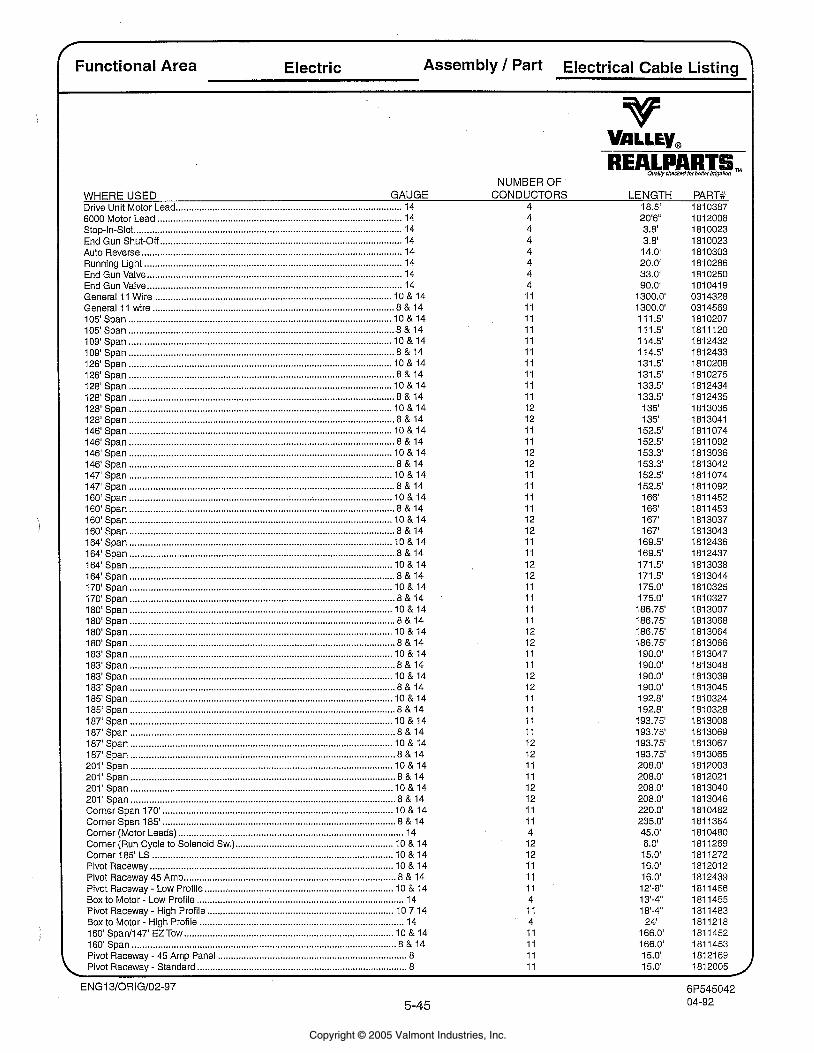
Functional Area Electric Assembly 1 Part Electrical Cable Listing
Ouallh.checkadlorbenar!rng~P~n '-
NUMBER OF WHERE USED GAUGE CONDUCTORS LENGTH PART# Drive Unit Motor Lead ....................................................................................... 14 4 18.5' 1810387
.............................................................................................. 6000 Motor Lead 14 Stop-In-Slot ....................................................................................................... 14 End Gun Shut-Off ............................................................................................. 14
.................................................................................................... Auto Reverse 14 Running Light ................................................................................................... 14 End Gun Valve .................................................................................................. 14
.................................................................................................. End Gun Valve 14 ........................................................................................... General 11 Wire 10 & 14 ............................................................................................. General I 1 wire 8 & 14
..................................................................................................... 105'Span 10 & 14
...................................................................................................... 105' Span 8 & 14
..................................................................................................... 109' Span 10 & 14
...................................................................................................... 109' Span 8 & 14
..................................................................................................... 126'Span 10 & 14
...................................................................................................... 126'Span 8 & 14 128'Span ..................................................................................................... 10 & 14 128' Span ...................................................................................................... 8 & 14
..................................................................................................... 128'Span 10 & 14 128' Span ...................................................................................................... 8 & 14
..................................................................................................... 146'Span 10 & 14 146'Span ...................................................................................................... 8 & 14 146'Span ..................................................................................................... 10 & 14 146' Span ...................................................................................................... 8 & 14 147'Span ..................................................................................................... 10 & 14 147' Span ...................................................................................................... 8 & 14 160' Span ..................................................................................................... 10 & 14 160' Span ...................................................................................................... 8 & 14 160'Span ..................................................................................................... 10 & 14 160' Span ...................................................................................................... 8 & 14 164' Span ..................................................................................................... 10 & 14 164' Span ...................................................................................................... 8 & 14 164' Span ..................................................................................................... 10 & 14 164' Span .................................................................................................... 8 & 14 170'Span ..................................................................................................... 10 & 14 170' Span ...................................................................................................... 8 & 14 180' Span .................................................................................................... 10 & 14 180' Span ...................................................................................................... 8 & 14 180' Span ..................................................................................................... 10 & 14 180' Span ...................................................................................................... 8 & 14 183'Span ..................................................................................................... 10 & 14 183' Span ...................................................................................................... 8 & 14 183'Span ..................................................................................................... 10 & 14 183' Span ...................................................................................................... 8 & 14 185'Span ..................................................................................................... 10 & 14 185' Span ...................................................................................................... 8 & 14 187'Span ..................................................................................................... 10 & 14 187'Span ...................................................................................................... 8 & 14 187'Span ..................................................................................................... 10 & 14 187' Span ...................................................................................................... 8 & 14 201'Span ..................................................................................................... 10 & 14 201' Span ...................................................................................................... 8 & 14 201' Span ..................................................................................................... 10 & 14 201 ' Span ...................................................................................................... 8 & 14 Corner Span 170' ......................................................................................... 10 & 14 Corner Span 185' ........................................................................................ 8 & 14
....................................................................................... Corner (Motor Leads) 14 ............................................................. Corner (Run Cycle to Solenoid Sw.) 10 & 14
Corner 185' LS ............................................................................................. 10 & 14 Pivot Raceway .............................................................................................. 10 & 14
.................................................................................. Pivot Raceway 45 Amp 8 & 14 ......................................................................... Pivot Raceway - Low Profile 10 & 14
................................................................................ Box to Motor - Low Profile 14 ........................................................................ Pivot Raceway - High Profile 10 7 14
Box to Motor - High Profile ............................................................................... 14 ................................................................................. 160' Span11 47' EZ Tow 10 & 14
160' Span ...................................................................................................... 8 & 14 ......................................................................... Pivot Racewav - 45 Amo Panel 8
, Pivot Raceway . Standard ................................................................................. 8 11 15.0'
Copyright © 2005 Valmont Industries, Inc.
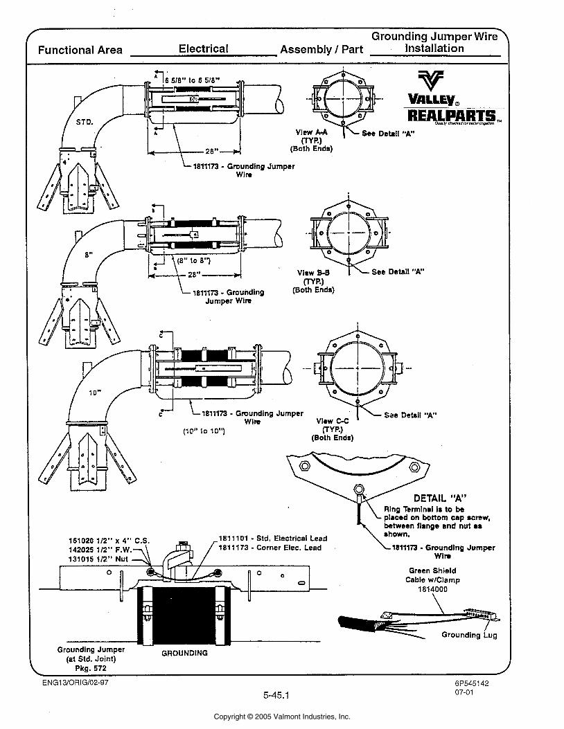
f Grounding Jumper ~ i r a
Functional Area Electrical Assembly / Part installation
REALPARTS, ous) checkadbrbansr ,n,gauon
1811173 - Grounding Jumper
See Detal "A"
1811173 - Grounding Jumper Sac Detail "A"
(10" lo 10") ( T W (Both Ends)
Rlng Termlnal I8 to be
1811 101 - Std. Electrical Lead 1811 173 - Corner Elec. Lead 1811173 - Groundlng Jumper
Wim
Green Shield Cable wlClamp
1814000
Grounding Jumper GROUNDING (at Std. Joint)
\ Pkg. 572 /
Copyright © 2005 Valmont Industries, Inc.
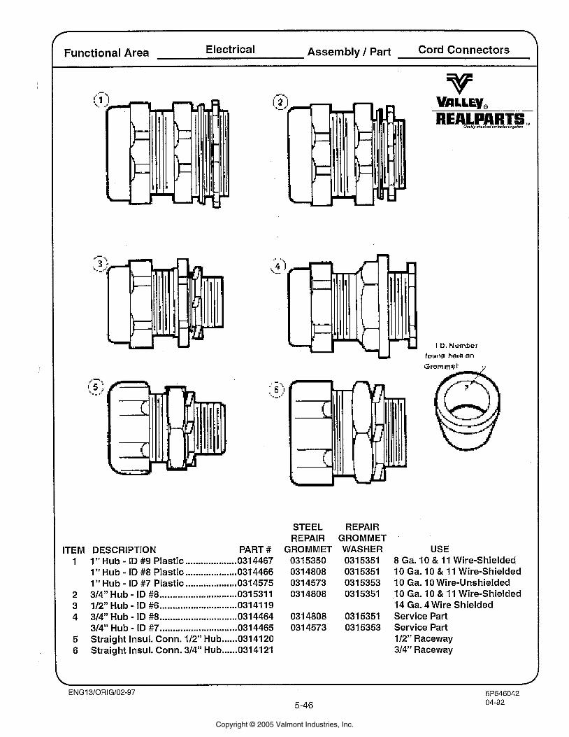
Functional Area Electrical Assembly 1 Part Cord Chm~ctors
ITEM DESCRIPTION .................... 1 1 " Hub - ID #9 Plastic 0314467 0315350
1" Hub - ID #8 Plastic .................... 0314466 0314808 1 " Hub - ID #7 Plastic .................... 031 4575 031 4573
2 314" Hub - ID #8 .............................. 031531 1 0314808 - .............................. 3 112" Hub ID #6 0314119
4 314" Hub - ID #8 .............................. 0314464 0314808 314" Hub - ID #7 .............................. 0314465 0314573
...... 5 Straight Insul. Conn. 112" Hub 0314120
...... 6 Straight Insul. Conn. 314" Hub 0314121
STEEL REPAIR REPAIR GROMMET
PART # GROMMET WASHER USE 0315351 8 Ga. 10 & 11 Wire-Shielded 0315351 10 Ga. 10 & 11 Wire-Shielded 0315353 10 Ga. 10 Wire-Unshielded 0315351 10 Ga. 10 & 11 Wire-Shielded
14 Ga. 4 Wire Shielded 0315351 Service Part 0315353 Service Part
112" Raceway 314" Raceway
Copyright © 2005 Valmont Industries, Inc.
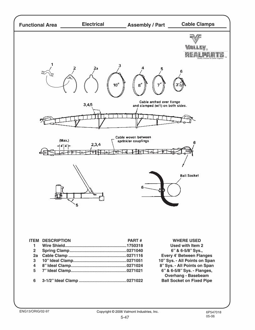
6P54701805-065-47
Quality checked for better irrigation
Assembly / PartElectricalFunctional Area Cable Clamps
ENG13/ORIG/02-97
ITEM DESCRIPTION PART # WHERE USED 1 Wire Shield .....................................................1750318 Used with Item 2 2 Spring Clamp .................................................0271040 6” & 6-5/8” Sys., 2a Cable Clamp ..................................................0271116 Every 4’ Between Flanges 3 10” Ideal Clamp..............................................0271051 10” Sys. - All Points on Span 4 8” Ideal Clamp................................................0271024 8” Sys. - All Points on Span 5 7” Ideal Clamp................................................0271021 6” & 6-5/8” Sys. - Flanges, Overhang - Basebeam 6 3-1/2” Ideal Clamp .........................................0271022 Ball Socket on Fixed Pipe
Copyright © 2006 Valmont Industries, Inc.
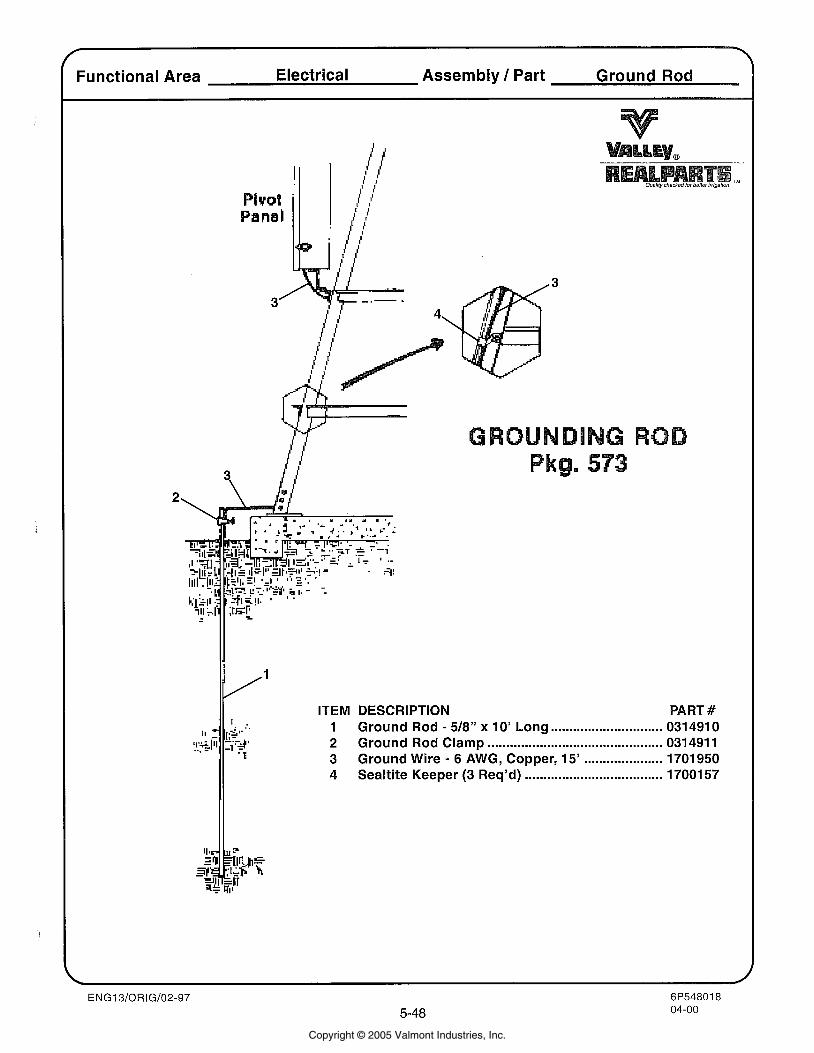
Functional Area Electrical Assembly 1 Part Ground Rod
ITEM DESCRIPTION PART # 1 Ground Rod - 518'' x 10' Long .............................. 0314910 2 Ground Rod Clamp ............................................. 031491 1 3 Ground Wire - 6 AWG, Copper, 15' ..................... 1701950 4 Sealtite Keeper (3 Req'd) ..................................... 1700157
Copyright © 2005 Valmont Industries, Inc.
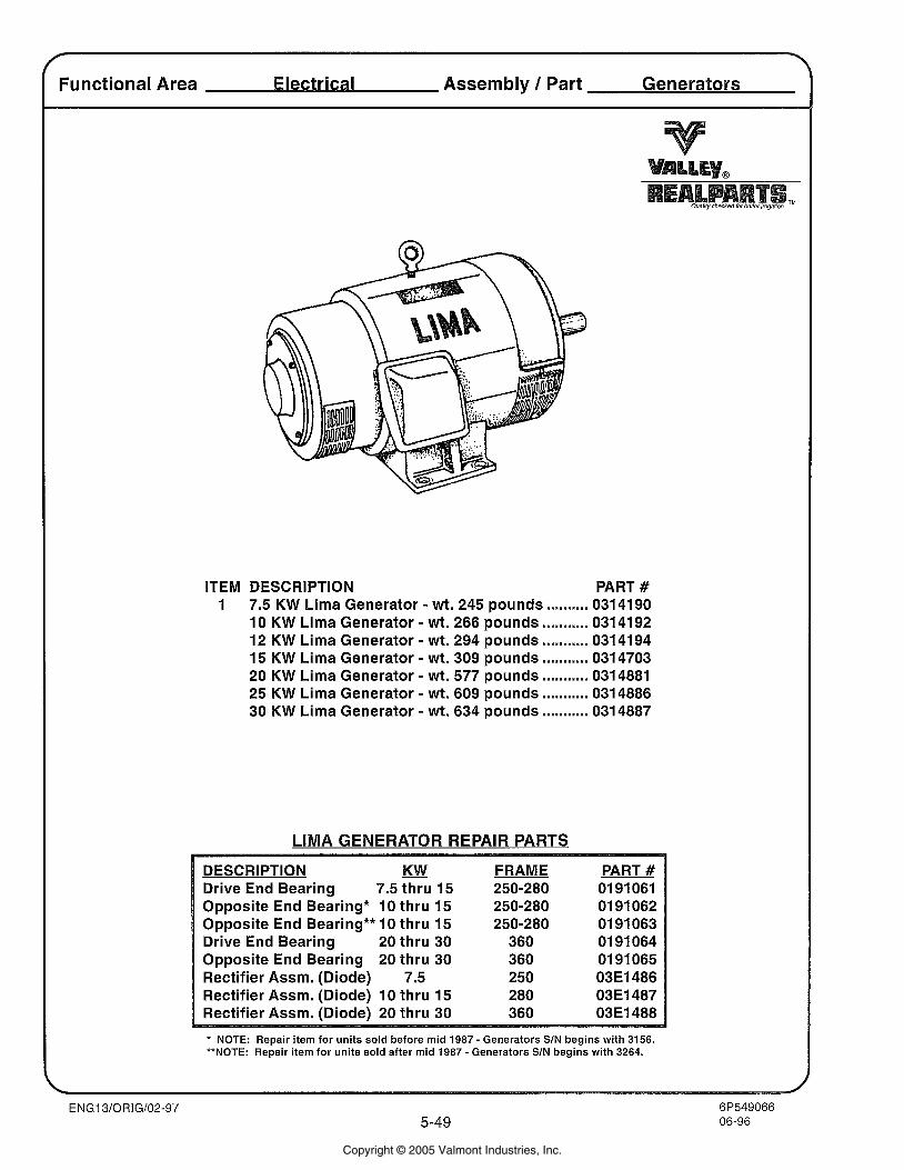
r
Functional Area Assembly / Part Generators
ITEM DESCRIPTION PART # 1 7.5 KW Lima Generator - wt. 245 pounds .......... 0314190
10 KW Lima Generator - wt. 266 pounds ........... 0314192 12 KW Lima Generator - wt. 294 pounds ........... 0314194 15 KW Lima Generator - wt. 309 pounds ........... 0314703 20 KW Lima Generator - wt. 577 pounds ........... 0314881 25 KW Lima Generator - wt. 609 pounds ........... 0314886 30 KW Lima Generator - wt. 634 pounds ........... 0314887
LIMA GENERATOR REPAIR PARTS
DESCRIPTION KW Drive End Bearing 7.5 thru 15 Opposite End Bearing* 10 thru 15 Opposite End Bearing** 10 thru 15 Drive End Bearing 20 thru 30 Opposite End Bearing 20 thru 30 Rectifier Assm. (Diode) 7.5 Rectifier Assm. (Diode) 10 thru 15 Rectifier Assm. (Diode) 20 thru 30
FRAME 250-280 250-280 250-280
360 360 250 280 360
PART # 01 91 061 01 91 062 01 91 063 01 91 064 01 91 065 O3El486 03E1487 03E1488
* NOTE: Repair item for units sold before mid 1987 - Generators SIN begins with 3156. **NOTE: Repair item for units sold after mid 1987 - Generators SIN begins with 3264.
Copyright © 2005 Valmont Industries, Inc.
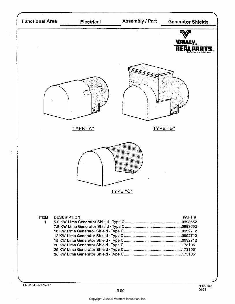
I Functional Area Electrical Assembly / Part Generator Shields
TYPE "A" TYPE "B"
ITEM DESCRIPTION PART # 1 5.0 KW Lima Generator Shield -Type C ..................................................... 0993652
7.5 KW Lima Generator Shield -Type C ..................................................... 0993652 10 KW Lima Generator Shield -Type C ...................................................... 099271 2 12 KW Lima Generator Shield -Type C ...................................................... 099271 2 15 KW Lima Generator Shield -Type C .................................................... 099271 2 20 KW Lima Generator Shield -Type C ...................................................... 1731051 25 KW Lima Generator Shield -Type C ................................................... 1731 051 30 KW Lima Generator Shield -Type C .................................................... 1731 051
Copyright © 2005 Valmont Industries, Inc.
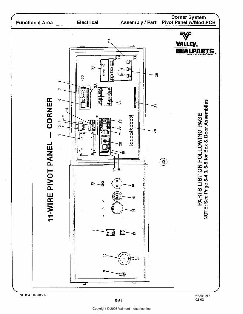
Corner System Y
Functional Area Electrical Assembly 1 Part Pivot Panel w/Mod PCB
REALPART& aus/;v chachsd lor banar/rr;g~Iiin
Copyright © 2005 Valmont Industries, Inc.
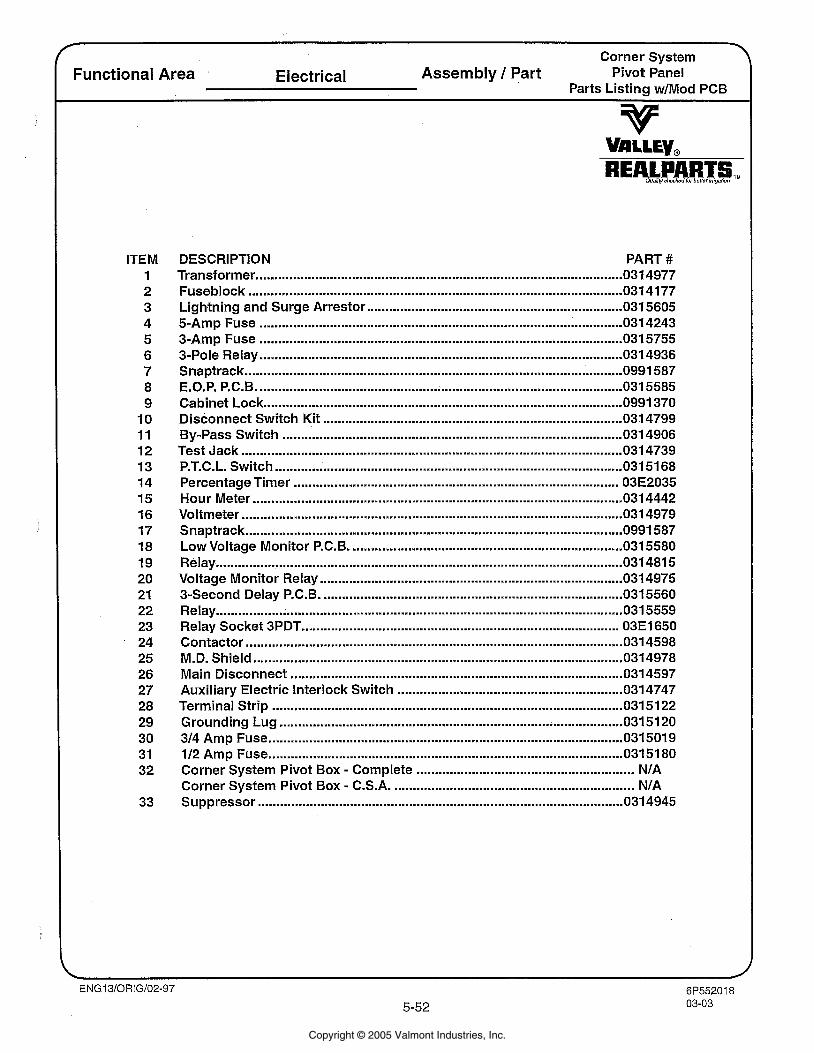
ITEM 1 2 3 4 5 6 7 8 9
10 11 12 13 14 15 16 17 18 19 20 21 22 23 24 25 26 27 28 29 30 3 1 32
T Corner System
Functional Area Electrical Assembly / Part Pivot Panel Parts Listing w1Mod PCB
v V!rrry, REALPART Ouel tchac*adlorba l l~ ) r~mgaf~~n TM
/
DESCRIPTION PART # ................................................................................................... Transformer 031 4977
Fuseblock .................................................................................................. 031 41 77 Lightning and Surge Arrestor ..................................................................... 0315605 5-Amp Fuse ................................................................................................. 031 4243 3-Amp Fuse .................................................................................................. 0315755 3-Pole Relay .................................................................................................. 0314936 Snaptrack ..................................................................................................... 0991 587 E.O.P. P.C.B. ............................................................................................... 035585 Cabinet Lock ............................................................................................ 0991 370
................................................................................. Disconnect Switch Kit 0 3 4799 By-Pass Switch .......................................................................................... 031 4906 Test Jack ....................................................................................................... 031 4739 P.T.C.L. Switch ............................................................................................. 03151 68 Percentage Timer ................................................................................. 03E2035 Hour Meter .................................................................................................... 031 4442 Voltmeter ....................................................................................................... 031 4979 Snaptrack ...................................................................................................... 0991 587 Low Voltage Monitor P.C.B. ......................................................................... 0315580 Relay .............................................................................................................. 031481 5
.................................................................................. Voltage Monitor Relay 0314975 3-Second Delay P.C.B. ................................................................................ 031 5560 Relay .............................................................................................................. 031 5559 Relay Socket 3PDT ................................................................................... 03E1650 Contactor .................................................................................................. 0314598 M.D. Shield .................................................................................................... 0314978
.......................................................................................... Main Disconnect 0314597 ............................................................. Auxiliary Electric Interlock Switch 0314747
Terminal Strip ............................................................................................... 03151 22 Grounding Lug ........................................................................................ 031 51 20
................................................................................................ 314 Amp Fuse 031 501 9 112 Amp Fuse ................................................................................................ 03151 80 Corner System Pivot Box . Complete .......................................................... NIA Corner System Pivot Box . C.S.A. ................................................................ NIA Suppressor ................................................................................................ 031 4945
Copyright © 2005 Valmont Industries, Inc.
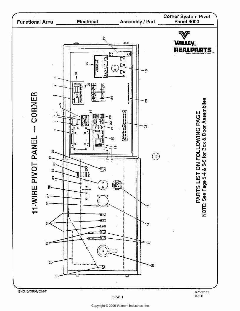
\ Corner System Pivot
Functional Area Electrical Assembly / Part Panel 6000
Copyright © 2005 Valmont Industries, Inc.
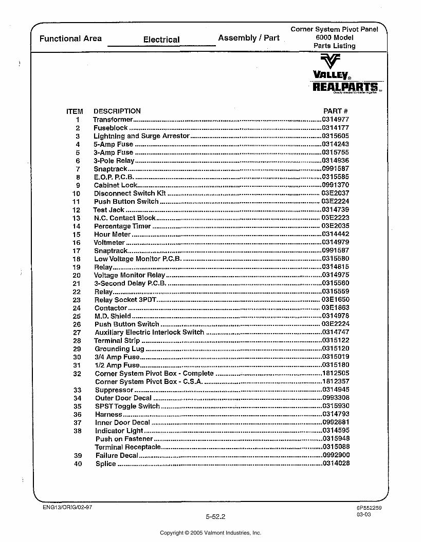
T
Corner System Pivot Panel Functional Area Electrical Assembly 1 Part 6000 Model
Parts Listing
ITEM 1 2 3 4 5 6 7 8 9
10 11 12 13 14 15 16 17 18 19 20 21 22 23 24 25 26 27 28 29 30 31 32
33 34 35 36 37 3 8
39 40
DESCRIPTION PART # Transformer ............................................................................................... 031 4977 Fuseblock ..................................................................................................... 031 4177 Lightning and Surge Arrestor ..................................................................... 0315605 5-Amp Fuse .............................................................................................. 031 4243 3-Amp Fuse .............................................................................................. 031 5755 3-Pole Relay ................................. .. .......................................................... 0314936 Snaptrack ..................................................................................................... 0991 587 E.O.P. P.C.6 ................................................................................................... 0315585 Cabinet Lock ............................................................................................... 0991 370 Disconnect Switch Kit ............................................................................... 03E2037 Push Button Switch ............................................................................. 03E2224 Test Jack ....................................................................................................... 031 4739 N.C. Contact Block ................................................................................... 03E2223 Percentage Timer ....................................................................................... 03E2035 Hour Meter ................................................................................................ 031 4442 Voltmeter ................................................................................................. 031 4979 Snaptrack ..................................................................................................... 0991 587 Low Voltage Monitor P.C.6 .......................................................................... 031 5580 Relay ........................................................................................................ 031 481 5
.................................................................................. Voltage Monitor Relay 031 4975 3-Second Delay P.C.B. ................................................................................. 031 5560 Relay ........................................................................................................... 0 3 5559 Relay Socket 3PDT ..................................................................................... 03E1650 Contactor ..................................................................................................... 03E1863 M.D. Shield .................................................................................................... 0314978 Push Button Switch ............................................................................. 03E2224
............................................................. Auxiliary Electric Interlock Switch 0314747 Terminal Strip ............................................................................................... 031 51 22
............................................................................................. Grounding Lug 031 51 20 314 Amp Fuse ............................................................................................ 0315019 112 Amp Fuse ............................................................................................... 031 51 80
. ..................................................... Corner System Pivot Box Complete 181 2505
. .............................................................. Corner System Pivot Box C.S.A. 181 2357 ................................................................................................... Suppressor 031 4945
Outer Door Decal ......................................................................................... 0993308 ..................................................................................... SPST Toggle Switch 031 5930
Harness ......................................................................................................... 031 4793 Inner Door Decal .......................................................................................... 0992881
.............................................................................................. Indicator Light 031 4595 Push on Fastener .................................................................................... 031 5948 Terminal Receptacle ................................................................................ 031 5088
................................................................................................. Failure Decal 0992900 Splice ............................................................................................................ 031 4028
Copyright © 2005 Valmont Industries, Inc.
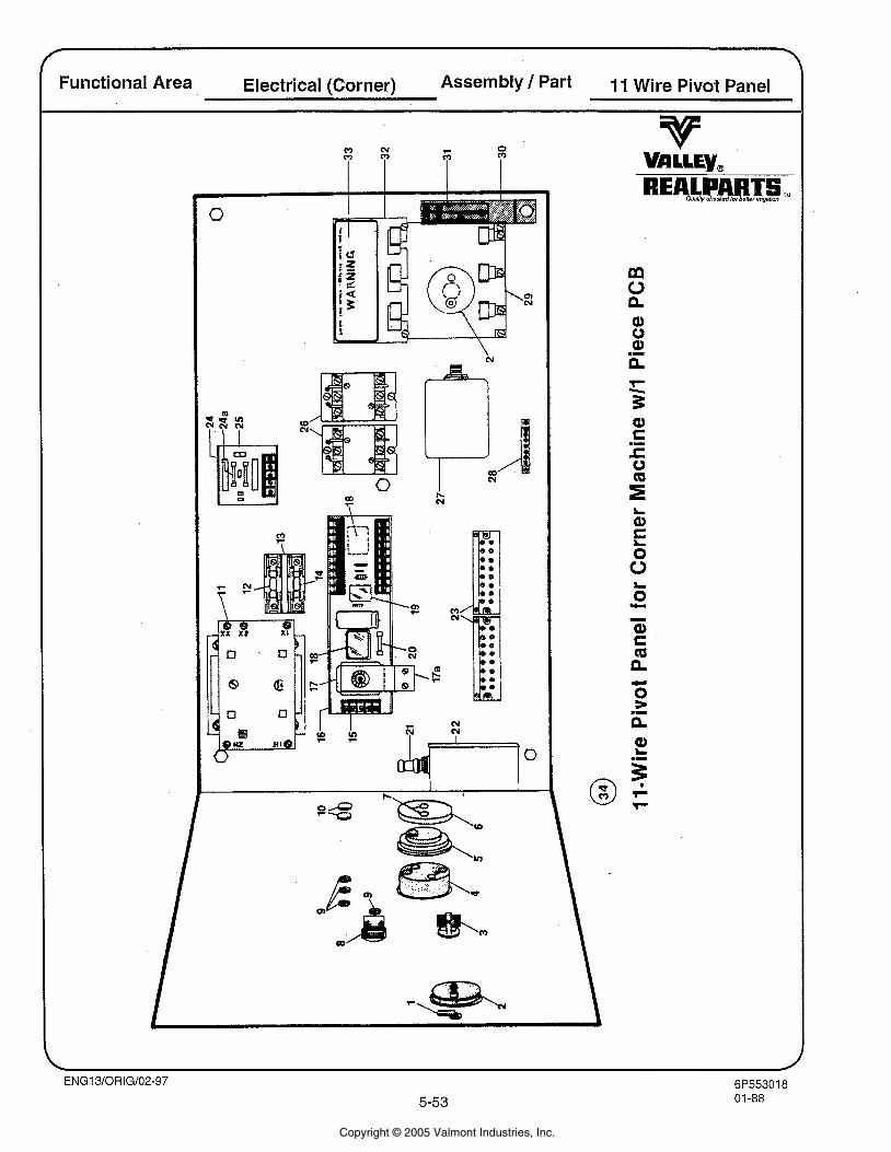
Functional Area Electrical (Corner) Assembly 1 Part 11 Wire Pivot Panel
Copyright © 2005 Valmont Industries, Inc.
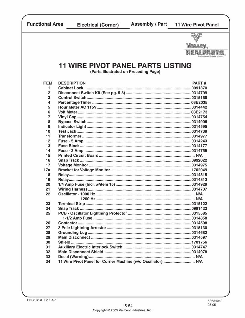
6P55404208-055-54
Quality checked for better irrigation
Assembly / PartElectrical (Corner)Functional Area
ENG13/ORIG/02-97
ITEM DESCRIPTION PART # 1 Cabinet Lock .................................................................................................0991370 2 Disconnect Switch Kit (See pg. 5-3) ...........................................................0314799 3 Control Switch ..............................................................................................0315168 4 Percentage Timer ........................................................................................ 03E2035 5 Hour Meter AC 115V .....................................................................................0314442 6 Volt Meter ..................................................................................................... 03E2173 7 Vinyl Cap .......................................................................................................0314754 8 Bypass Switch ..............................................................................................0314906 9 Indicator Light ..............................................................................................0314595 10 Test Jack .......................................................................................................0314739 11 Transformer ..................................................................................................0314977 12 Fuse - 5 Amp ................................................................................................0314243 13 Fuse Block ....................................................................................................0314177 14 Fuse - 3 Amp ................................................................................................0314755 15 Printed Circuit Board ...................................................................................... N/A 16 Snap Track ....................................................................................................0992022 17 Voltage Monitor ............................................................................................0314975 17a Bracket for Voltage Monitor .........................................................................1702049 18 Relay ..............................................................................................................0314815 19 Relay ..............................................................................................................0314813 20 1/4 Amp Fuse (Incl. w/item 15) ....................................................................0314929 21 Wiring Harness .............................................................................................0314737 22 Oscillator - 1000 Hz ......................................................................................... N/A 1200 Hz ......................................................................................... N/A 23 Terminal Strip ...............................................................................................0315122 24 Snap Track ....................................................................................................0991422 25 PCB - Oscillator Lightning Protector .........................................................0315585 1-1/2 Amp Fuse ........................................................................................0314858 26 Contactor ......................................................................................................0314598 27 3 Pole Lightning Arrestor ............................................................................0315130 28 Grounding Lug .............................................................................................0314682 29 Main Disconnect ..........................................................................................0314597 30 Shield ............................................................................................................1701756 31 Auxiliary Electric Interlock Switch .............................................................0314747 32 Main Disconnect Shield ...............................................................................0314978 33 Decal (Warning) ............................................................................................... N/A 34 11 Wire Pivot Panel for Corner Machine (w/o Oscillator) ............................ N/A
11 Wire Pivot Panel
11 WIRE PIVOT PANEL PARTS LISTING(Parts Illustrated on Preceding Page)
Copyright © 2005 Valmont Industries, Inc.
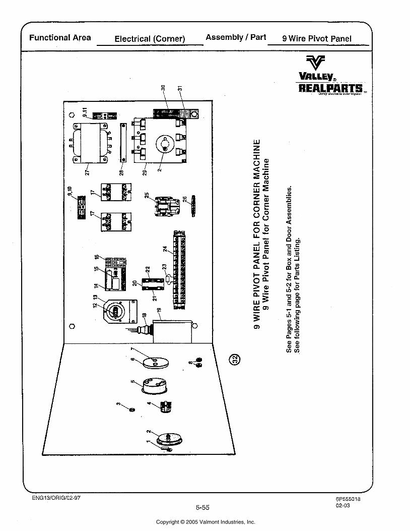
Functional Area Electrical (Corner) Assembly Part 9 Wire Pivot Panel
Copyright © 2005 Valmont Industries, Inc.
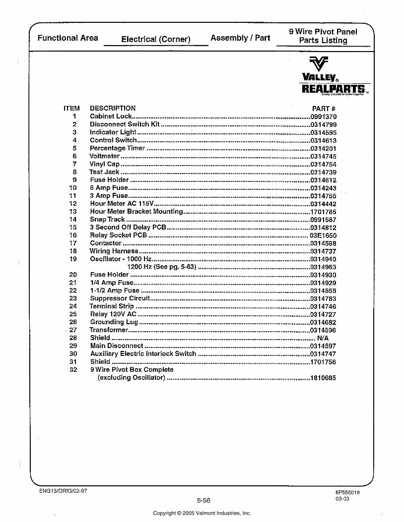
9 Wire Pivot Panel Functional Area Electrical (Corner) Assembly 1 Part Parts Listing
ITEM 1 2 3 4 5 6 7 8 9
10 11 12 13 14 15 16 17 18 19
20 21 22 23 24 25 26 27 28 29 30 31 32
DESCRIPTION PART # ................................................................................................. Cabinet Lock 0991370
................................................................................. Disconnect Switch Kit 031 4799 .............................................................................................. Indicator Light 031 4595 .............................................................................................. Control Switch 031 461 3
Percentage Timer ....................................................................................... 031 4201 ....................................................................................................... Voltmeter 031 4745
Vinyl Cap ....................................................................................................... 031 4754 Test Jack ....................................................................................................... 031 4739 Fuse Holder .................................................................................................. 031 461 2 5 Amp Fuse ................................................................................................... 0314243
................................................................................................... 3 Amp Fuse 0314755 Hour Meter AC 11 5V ..................................................................................... 031 4442 Hour Meter Bracket Mounting .................................................................. 1701785 Snap Track ............................................................................................... 0991 587 3 Second Off Delay PCB ........................................................................... 031481 2 Relay Socket PCB .................................................................................. 03E1650 Contactor ................................................................................................... 031 4598
............................................................................................. Wiring Harness 031 4737 Oscillator . 1000 Hz ..................................................................................... 031 4940
1200 Hz (See pg . 5-63) ............................................................. 031 4963 Fuse Holder .................................................................................................. 031 4930 114 Amp Fuse .............................................................................................. 0314929 1-112 Amp Fuse ............................................................................................ 0314858 Suppressor Circuit ....................................................................................... 0314783 Terminal Strip ............................................................................................. 031 4746 Relay 120V AC ....................................................................................... 031 4727 Grounding Lug ....................................................................................... 031 4682
................................................................................................... Transformer 0314596 Shield ......................................................................................................... NIA Main Disconnect ......................................................................................... 0314597 Auxiliary Electric Interlock Switch ............................................................. 0314747 Shield ............................................................................................................ 1701 756 9 Wire Pivot Box Complete
(excluding Oscillator) .............................................................................. 181 0685
Copyright © 2005 Valmont Industries, Inc.
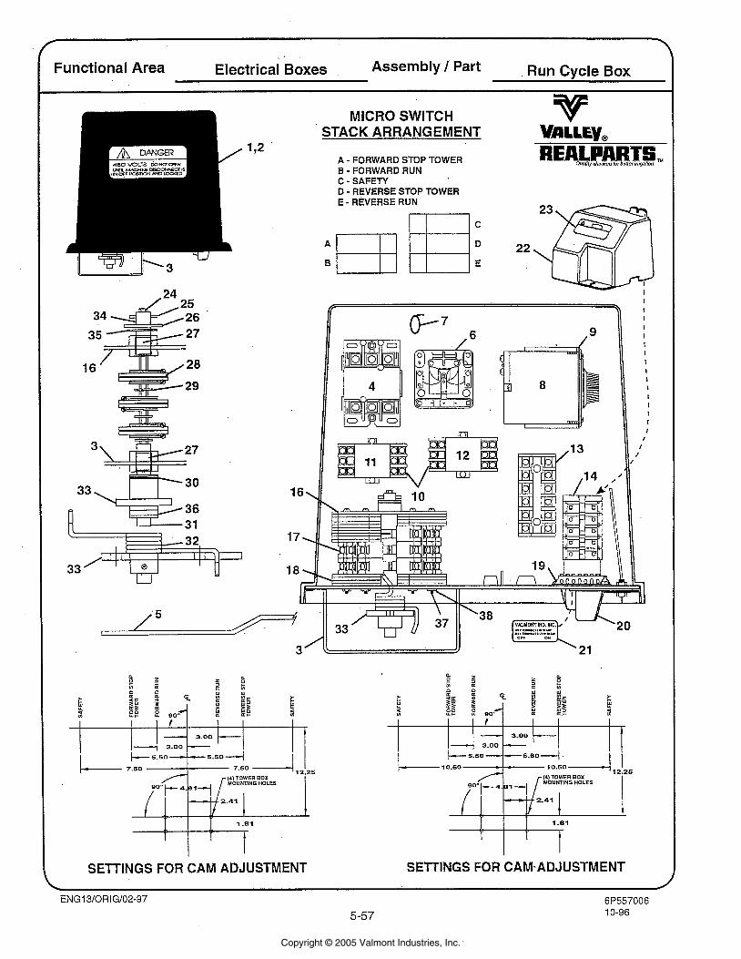
Functional Area Electrical Boxes Assembly 1 Part Run Cycle Box
r, SETTINGS FOR CAM ADJUSTMENT
MICRO SWITCH STACK ARRANGEMENT VALLE~~
A - FORWARD STOP TOWER B - FORWARD RUN C - SAFETY D - REVERSE STOP TOWER E - REVERSE RUN
SElTlNGS FOR CAM-ADJUSTMENT
Copyright © 2005 Valmont Industries, Inc.
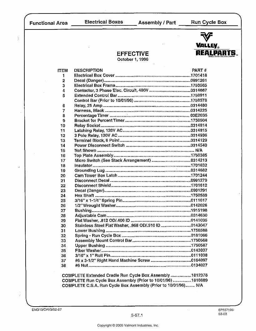
Functional Area Electrical Boxes Assembly 1 Part Run Cycle Box
ITEM 1 2 3 4 5
6 7 8 9
10 11 12 13 14 15 16 17 18 19 20 21 22 23 24 25 26 27 28 29 30 3 1 32 33 34 35 36 37 38
EFFECTIVE October 1. 1996
DESCRIPTION PART # Electrical Box Cover ............................................................. 170141 8 Decal (Danger) ...................................................................... 0991 261 Electrical Box Frame ................................................................. 1750565
.................................... Contactor. 3 Phase Elec . Circuit. 480V 0314667 Extended Control Bar ............................................................... 175091 1 Control Bar (Prior to 1 0/01/96) ................................................. 1750578 Relay. 25 Amp .......................................................................... 0 4480 Harness. Black ....................................................................... 0 3 4225 Percentage Timer ..................................................................... 03E2035 Bracket for Percent Timer ......................................................... 1750504 Relay Socket ............................................................................. 0 481 4 Latching Relay. 120V AC ........................................................... 0314815 3 Pole Relay. 120V AC ........................................................... 0 3 4936 Terminal Block. 6 Point .......................................................... 0314129 Power Disconnect Switch ..................................................... 0314540 Not Shown ............................................................................... NIA Top Plate Assembly .............................................................. 1750385
.................................. Micro Switch (See Stack Arrangement) 0314213 Insulator .................................................................................... 1701 632
............ Grounding Lug ....................................................... 031 4682 Cam Tower Box Latch ............................................................... 1701 244 Disconnect Decal ................................................................... 0991 279 Disconnect Shield ..................................................................... 1701 61 2 Decal (Danger) ....................................................................... 0991 291 Hex Shaft ................................................................................. 1750589 3/16" x 1-114'' Spring Pin ........................................................... 0 11017 112" Wrought Washer .............................................................. 01 42026 Bushing ..................................................................................... 191 5198 Adjustable Cam ........................................................................ 0314630 Flat Washer. . 812 ODl.406 ID .................................................. 0141035
.......................... Stainless Steel Flat Washer. . 968 ODl.510 ID 0143047 Lower Bushing .......................................................................... 1750588 Spring . Run Cycle Box ........................................................ 0181 066 Assembly Mount Control Bar ................................................... 1750568 Upper Bushing .......................................................................... 1750587 Fiber Washer .......................................................................... 01 43037 311 6" x 1" Roll Pin .................................................................... 0 11 038
................................... #6 x 3-112'' Right Hand Machine Screw 0164097 #6 Nut ..................................................................................... 0134027
COMPLETE Extended Cradle Run Cycle Box Assembly .................. 1812378 COMPLETE Run Cycle Box Assembly (Prior to 1 0/01/96) ................ 181 0889
........ COMPLETE C.S.A. Run Cycle Box Assembly (Prior to 10/01/96) N/A
Copyright © 2005 Valmont Industries, Inc.
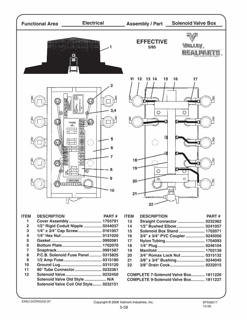
6P55801710-065-58
Quality checked for better irrigation
Assembly / PartElectricalFunctional Area
ENG13/ORIG/02-97
ITEM DESCRIPTION PART # 1 Cover Assembly ............................. 1703791 2 1/2” Rigid Coduit Nipple ................ 0244037 3 1/4” x 3/4” Cap Screw ..................... 0161057 4 1/4” Hex Nut .................................... 0131020 5 Gasket ............................................. 0992081 6 Bottom Plate ................................... 1702070 7 Snaptrack ........................................ 0991587 8 P.C.B. Solenoid Fuse Panel ........... 0315825 9 1/2 Amp Fuse .................................. 0315180 10 Ground Lug ..................................... 0315120 11 90° Tube Connector ........................ 0232361 12 Solenoid Valve ................................ 0232450 Solenoid Valve Old Style ................... N/A Solenoid Valve Coil Old Style ........ 0232151
Solenoid Valve Box
EFFECTIVE5/85
13 Straight Connector ........................ 0232362 14 1/2” Bushed Elbow ......................... 0241057 15 Solenoid Box Stand ....................... 1702071 16 3/4” x 3/4” PVC Coupler ................. 0245050 17 Nylon Tubing ................................... 1704093 18 1/4” Plug .......................................... 0246104 19 Manifold .......................................... 1703139 20 3/4” Romax Lock Nut ..................... 0315132 21 3/8” x 3/4” Bushing ......................... 0244045 22 3/8” Drain Cock ............................... 0232015
COMPLETE 7-Solenoid Valve Box ............ 1811226 COMPLETE 9-Solenoid Valve Box ............ 1811227
ITEM DESCRIPTION PART #
Copyright © 2006 Valmont Industries, Inc.
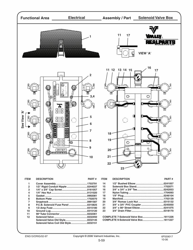
6P55901710-06
Assembly / PartFunctional Area Electrical Solenoid Valve Box
14 1/2" Bushed Elbow ........................................024105715 Solenoid Box Stand.......................................170207116 3/4" x 3/4" x 3/4" Tee ......................................024205317 Nylon Tubing ..................................................170409318 1/4" Plug .........................................................024610419 Manifold ..........................................................170313920 3/4" Romax Lock Nut ....................................031513221 3/4" x 3/4" PVC Coupler ................................024505022 3/4" x 90o Street Elbow ..................................024107523 3/4" Drain Filter ..............................................0318170 COMPLETE 7-Solenoid Valve Box ..............................1811226COMPLETE 9-Solenoid Valve Box ..............................1811227
ITEM DESCRIPTION PART # ITEM DESCRIPTION PART #
1 Cover Assembly ............................................1703791 2 1/2" Rigid Conduit Nipple .............................0244037 3 1/4" x 3/4" Cap Screw ....................................0161057 4 1/4" Hex Nut ...................................................0131020 5 Gasket ............................................................0992081 6 Bottom Plate ..................................................1702070 7 Snaptrack .......................................................0991587 8 P.C.B. Solenoid Fuse Panel ..........................0315825 9 1/2 Amp Fuse .................................................0315180 10 Ground Lug ....................................................0315120 11 90o Tube Connector .......................................0232361 12 Solenoid Valve ...............................................0232450 Solenoid Valve Old Style ...............................0232145 Solenoid Valve Coil Old Style .......................0232151
1
5
6
7
8
9
10
2
12 13 14 17
18
20
19
5-59
21
11 17
VIEW 'A'
1615
23
See
Vie
w 'A
'
22
11
3,4
ENG13/ORIG/02-97 Copyright © 2006 Valmont Industries, Inc.
Functional Area Electrical Assembly 1 Part Blank Page
This page intentionally left blank.
Copyright © 2005 Valmont Industries, Inc.
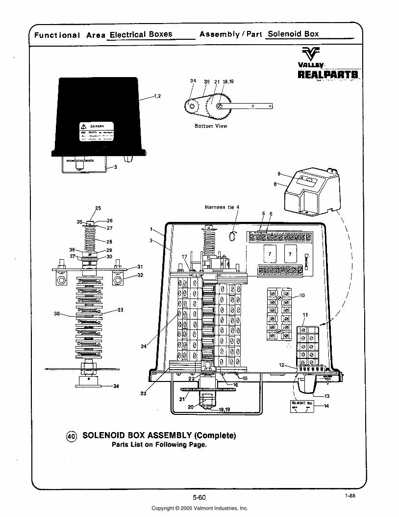
Funct ional Area Electrical Boxes Assembly / Part Solenoid Box
Bottom View
@ SOLENOID BOX ASSEMBLY (Complete) Parts List on Following Page.
Copyright © 2005 Valmont Industries, Inc.
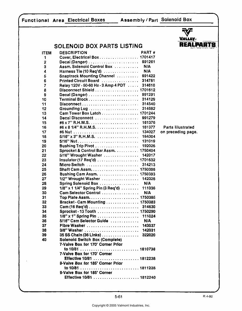
Functional Area Electrical Boxes Assembly / Part Solenoid Box
ITEM 1 2 3 4 5 6 7 8 9
10 11 12 13 14 15 16 17 18 19 20 21 22 23 24 25 26 27 28 29 30 31 32 33 34 35 36 37 38 39 40
SOLENOID BOX PARTS LISTING DESCRIPTION PART #
. . . . . . . . . . . . . . . . . . Cover. Electrical Box 170141 7 . . . . . . . . . . . . . . . . . . . . . . . Decal(Danger) 991261
. . . . . . . . . . . . Assm Solenoid Control Box NIA . . . . . . . . . . . . . . . . Harness Tie (10 Req'd) NIA
. . . . . . . . . . Snaptrack Mounting Channel 991422 . . . . . . . . . . . . . . . . . Printed Circuit Board 314781
. . . . . . . Relay 120V 50-60 Hz 3 Amp 4 PDT 314610 . . . . . . . . . . . . . . . . . . . . Disconnect Shield 1701 612
. . . . . . . . . . . . . . . . . . . . . . . Decal (Danger) 991291 Terminal Block . . . . . . . . . . . . . . . . . . . . . . . 314129 Disconnect . . . . . . . . . . . . . . . . . . . . . . . . . . 314540 Grounding Lug . . . . . . . . . . . . . . . . . . . . . . . 314682
. . . . . . . . . . . . . . . . . Cam Tower Box Latch 1701 244 . . . . . . . . . . . . . . . . . . . . Decal Disconnect 991279
#6x7"R.H.M.S . . . . . . . . . . . . . . . . . . . . . . . 161376 #6 x 8 114" R.H.M.S. . . . . . . . . . . . . . . . . . . . 161377 Parts Illustrated
. #6 Nut . . . . . . . . . . . . . . . . . . . . . . . . . . . . . . 134027 on preceding page . . . . . . . . . . . . . . . . . . . 5116" x 3" R . H .M. S. 164004
5/16" Nut . . . . . . . . . . . . . . . . . . . . . . . . . . . . 131019 Bushing Trip Pivot . . . . . . . . . . . . . . . . . . . . 192026 Sprocket & Control Bar Assm . . . . . . . . . . . 1750404 5116" Wrought Washer . . . . . . . . . . . . . . . . 142017 Insulator (1 7 Req'd) . . . . . . . . . . . . . . . . . . . 1701 632 Micro Switch . . . . . . . . . . . . . . . . . . . . . . . . 314213 Shaft Cam Assm . . . . . . . . . . . . . . . . . . . . . . 1750396 Bushing Cam Assm . . . . . . . . . . . . . . . . . . . 1750393 112" Wrought Washer . . . . . . . . . . . . . . . . . 142026 Spring Solenoid Box . . . . . . . . . . . . . . . . . . NIA 118" x 1 114" Spring Pin (3 Req'd) . . . . . . . . 11 1036 Cam Selector Control . . . . . . . . . . . . . . . . . NIA Top Plate Assm . . . . . . . . . . . . . . . . . . . . . . . 1750385 Bracket . Cam Mounting . . . . . . . . . . . . . . . 1750383 Cam (1 6 Req'd) . . . . . . . . . . . . . . . . . . . . . . . 31 4630 Sprocket . 13 Tooth . . . . . . . . . . . . . . . . . . . 1750290 118" x 1" Spring Pin . . . . . . . . . . . . . . . . . . . 111024 5/16" Cam Selector Guide . . . . . . . . . . . . . NIA Fibrewasher . . . . . . . . . . . . . . . . . . . . . . . . 143037 318"Washer . . . . . . . . . . . . . . . . . . . . . . . . . 142031 35SSChain(36Links) . . . . . . . . . . . . . . . . . 322020 Solenoid Switch Box (Complete) 7.Valve Box for 170' Corner Prior
to10181 . . . . . . . . . . . . . . . . . . . . . . . . . . . 1810738 7-Valve Box for 170' Corner
Effective 10181 . . . . . . . . . . . . . . . . . . . . . 1812238 94alve Box for 185' Corner Prior
to 10181 . . . . . . . . . . . . . . . . . . . . . . . . . . . 181 1228 9-Valve Box for 185' Corner
Effective 10181 . . . . . . . . . . . . . . . . . . . . . 1812240
Copyright © 2005 Valmont Industries, Inc.
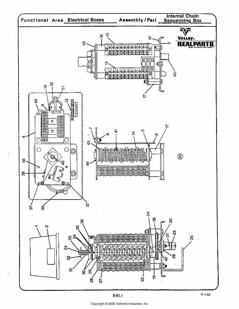
Internal Chain Y Funct lonal Area Electrical Boxes Asrsmbly Part Sequencing Box -
Copyright © 2005 Valmont Industries, Inc.
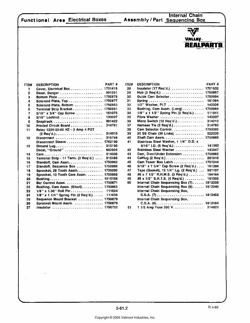
/ Internal Chain \ ............
Funct ional Area Electrical Boxes Assembly I Part - Sequencing BOX
ITEM 1 2 3 4 5 6 7 8 9
10 11
12
13
14 15 16 17 18 19 20 21 22 23 24 25 26 27
DESCRIPTION PART # ................. Cover. Electrical Box 1701 41 8
....................... Decal. Danger 991261 ........................ Bottom Plate 1750878
.................. Solenoid Plate. Top 1750877 ............... Solenoid Plate. Bottom 1750883
................ Terminal Strip Bracket 1750881 .............. 5/16" x 314" Cap Screw 161076
5/16" Locknut ...................... 133007 Snaptrack .......................... 991422
................. Printed Circuit Board 314781 Relay 120V-50-60 HZ . 3 Amp 4 PDT
........................ (2 Req'd.). 314610 Disconnect ......................... 315746 Disconnect Sleeve ................... 1702190
......................... Ground Lug 315190 .................... Decal. "Ground" 992925
Cam ............................... 314630 Terminal Strip . 11 Term . (2 Req'd.) .... 315485 Standoff. Cam Assm .................. 1750862 Standoff. Sequence Box .............. 1750866
.............. Sprocket. 28 Tooth Assm 1750290 Sprocket. 13 Tooth Cam Assm ......... 1750868 Bushing ............................ 1915198 Bar Control Assm .................... 1750871 Bushing. Cam Assm . (Short) ........... 1750865 118" x 1.00" Roll Pin ................. 111024 118" x 1 114" Spring Pin (2 Req'd.) ..... 111036 Sequence Mount Bracket ............. 1750879 Sprocket Mount Assm ................ 1750876 Insulator ........................... 1750722
ITEM 28 29 30 31 32 33 34 35 36 37 38 39 40 41
42 43 44 45 46 47 48 49 50
5 1
DESCRIPTION PART # Insulator (17 Req'd.) ................. 1701632 Hub (2 Req'd.) ...................... 1750867 Guide Cam Selector . ................. 1750884 Spring ............................. 181064 112" Washer. PLT ................... 142026 Bushing. Cam Assm . (Long) ........... 1750864 118" x 1 112" Spring Pin (2 Req'd.) . . . . . 111041 Fibre Washer . ...................... 143037 Micro Switch (18 Req'd.) .............. 314213 Harness Tie (2 Req'd.). ............... 314793 Cam Selector Control . ................ 1750392 35 SS Chain (36 Links) ............... 322020 Shaft Cam Assm ..................... 1750869 Stainless Steel Washer. 1 114" O.D. x
................ 9/16'' I.D. (8 Req'd.) 141062 Stainless Steel Washer ............... 143047 Cam. OverlUnder Extension ........... 1750863 CaPlug (2 Req'd.) .................... 261010 Cam Tower Box Latch ................ 1701244 5/16" x 7 314" Cap Screw (2 Req'd.) .... 161388 Tape (Gasket). 12 114" Lg . (2 Req'd.) ... 991197 #6 x 7 112" R.H.M.S. (3 Req'd.) ........ 164164 #8 x 112" S.H.T.S. (4 Req'd.) .......... 161355 Internal Chain Sequencing Box (7) ...... 1812238 Internal Chain Sequencing Box (9) ...... 1812240 lnternal Chain Sequencing Box.
C.S.A.( 7) ......................... 1812402 lnternal Chain Sequencing Box.
. . . . . . . . . . . . . . . . . . . . . . . . . C.S.A. (9) 1812404 ................ 1 112 Amp Fuse 250 V 31 4823
Copyright © 2005 Valmont Industries, Inc.
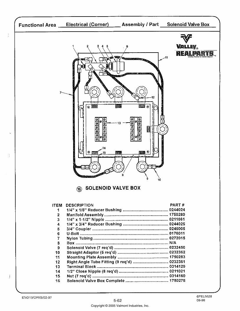
Functional Area Electrical (Corner) Assembly / Part Solenoid Valve Box
ITEM I 2 3 4 5 6 7 8 9
10 11 12 13 14 15 16
@ SOLENOID VALVE BOX
DESCRIPTION PART # 114" x 118'' Reducer Bushing ......................................... 0244024
.......................................................... Manifold Assembly 1750280 ......................................................... 114" x 1-112" Nipple 0211081
114" x 314" Reducer Bushing ......................................... 0244025 ..................................................................... 314" Coupler 0245005
U-Bolt ................................................................................ 0176011 Nylon Tubing ................................................................. 027201 5 Box .................................................................................... NIA
................................................. Solenoid Valve (7 req'd) 0232450 .............................................. Straight Adaptor (5 reqJd) 0232362
Mounting Plate Assembly .............................................. 1750283 Right Angle Tube Fitting (9 req'd) ................................ 0232361 Terminal Block ............................................................... 0314129 112" Close Nipple (8 req'd) ............................................ 0211021 Nut (7 req'd) ..................................................................... 0314160 Solenoid Valve Box Complete ....................................... 1750278
Copyright © 2005 Valmont Industries, Inc.
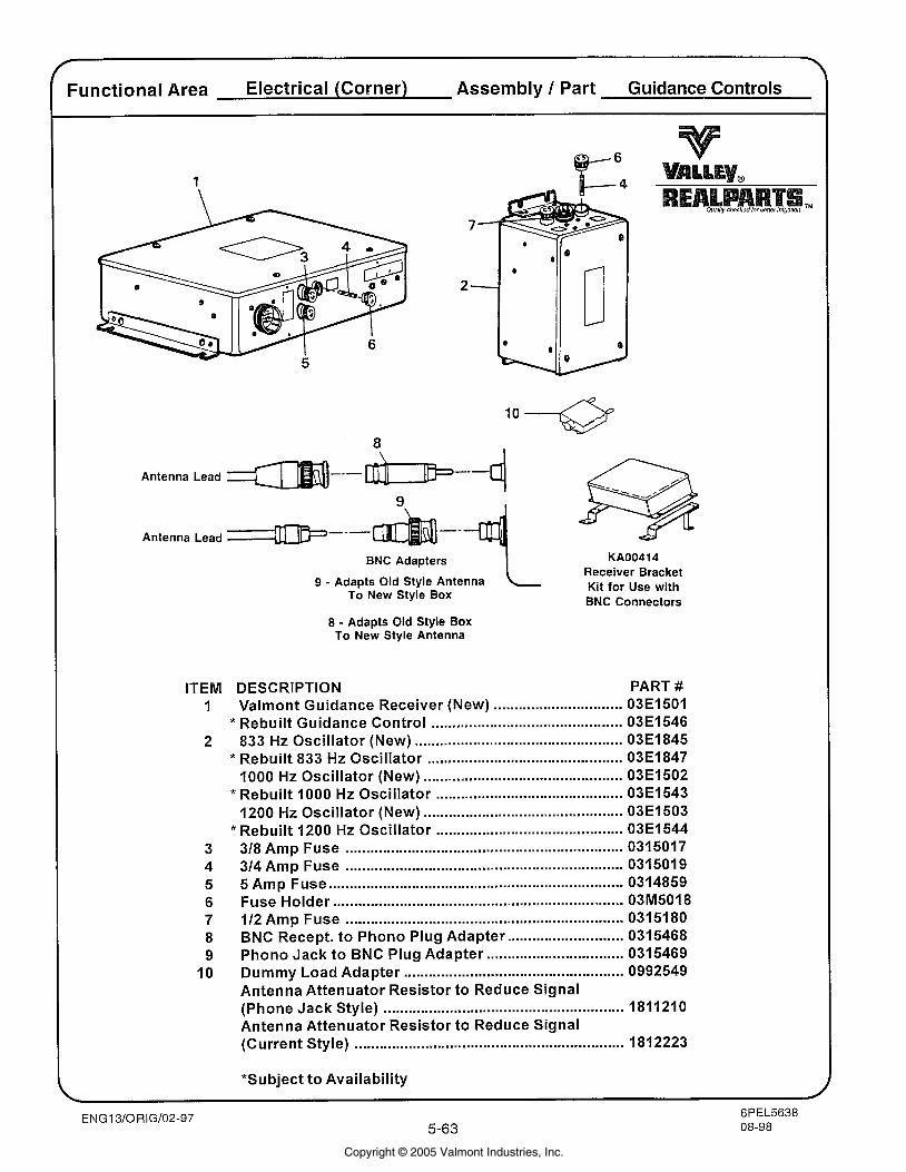
Functional Area Electrical (Corner) Assembly 1 Part Guidance Controls
Antenna Lead
Antenna Lead ~ I L P - - - ---d BNC Adaoters I KA00414 r - -
Receiver Bracket 9 - Adapts Old Style Antenna Kit for Use with
To New Style Box BNC Connectors
8 - Adapts Old Style Box To New Style Antenna
ITEM DESCRIPTION PART # 1 Valmont Guidance Receiver (New) ............................... 03E1501
* Rebuilt Guidance Control .............................................. 03E1546 2 833 Hz Oscillator (New) .................................................. 03E1845
* Rebuilt 833 Hz Oscillator ............................................... 03E1847 1000 Hz Oscillator (New) ................................................ 03E1502
* Rebuilt 1000 Hz Oscillator ............................................. 03E1543 1200 Hz Oscillator (New) ................................................ 03E1503
* Rebuilt 1200 Hz Oscillator ............................................. 03E1544 3 318 Amp Fuse ................................................ ................ 0315017 4 314 Amp Fuse ................................................................... 0315019 5 5 Amp Fuse ...................................................................... 0314859 6 Fuse Holder .................................................................. 03M5018 7 112 Amp Fuse ................................................................... 0315180 8 BNC Recept. t o Phono Plug Adapter ............................ 0315468 9 Phono Jack t o BNC Plug Adapter ................................. 0315469
10 Dummy Load Adapter ..................................................... 0992549 Antenna Attenuator Resistor t o Reduce Signal (Phone Jack Style) .......................................................... 1811210 Antenna Attenuator Resistor to Reduce Signal (Current Style) ................................................................. 1812223
*Subject t o Availability
Copyright © 2005 Valmont Industries, Inc.
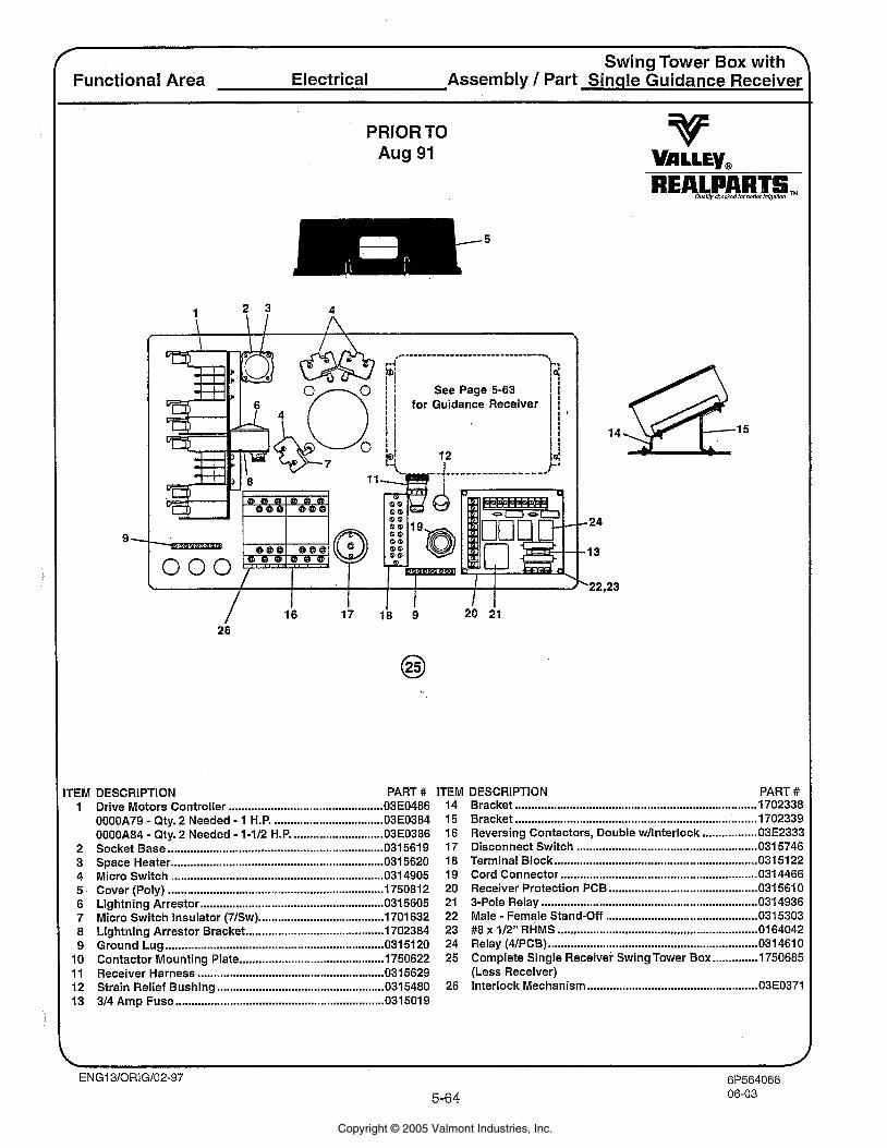
Swing Tower Box with ' Functional Area Electrical Assembly 1 Part Sinqle Guidance Receiver
PRIOR TO Aug 91
See Page 5-63 for Guidance Receiver ,
TEM DESCRIPTION PART # ITEM DESCRIPTION PART # ........................................................................... ................................................ 1 Drive Motors Controller 03E0486 14 Bracket 1702338 ...................................................................... .................................. 0000A79 - Qty. 2 Needed - 1 H.P. 03E0384 15 Bracket 1702339
................. 0000A84 - Qty. 2 Needed - 1-112 H.P ............................. 03E0386 16 Reversing Contactors, Double wllnterlock 03E2333 ........................................................ 2 Socket Base .................................................................. 0315619 17 Disconnect Switch 0315746
............................................................... 3 Space Heater .................................................................. 0315620 18 Terminal Block 0315122 ............................................................. 4 Micro Switch ................................................................. 031 4905 19 Cord Connector 0 3 4466
.............................................. 5 Cover (Poly) ................................................................... 750812 20 Receiver Protection PCB 031 561 0 ..............................................*.......... ................................................................... 6 Lightning Arrestor 0315605 21 3-Pole Relay 0 3 4936
............................................... 7 Micro Switch Insulator (71Sw) ....................................... 1701 632 22 Male - Female Stand-Off 031 5303 8 Lightning Arrestor Bracket ........................................... 1702384 23 #8 x 112'' RHMS ............................................................. 0164042 9 Ground Lug .................................................................... 031 5120 24 Relay (4lPCB) ................................................................. 031 461 0
.............. 10 Contactor Mounting Plate ............................................. 1750622 25 Complete Single Receiver Swing Tower Box 1750685 11 Receiver Harness .......................................................... 0315629 (Less Receiver) 12 Strain Relief Bushing .................................................. 035480 26 Interlock Mechanism ..................................................... 03E0371
................................................................. 13 314 Amp Fuse 0315019
Copyright © 2005 Valmont Industries, Inc.
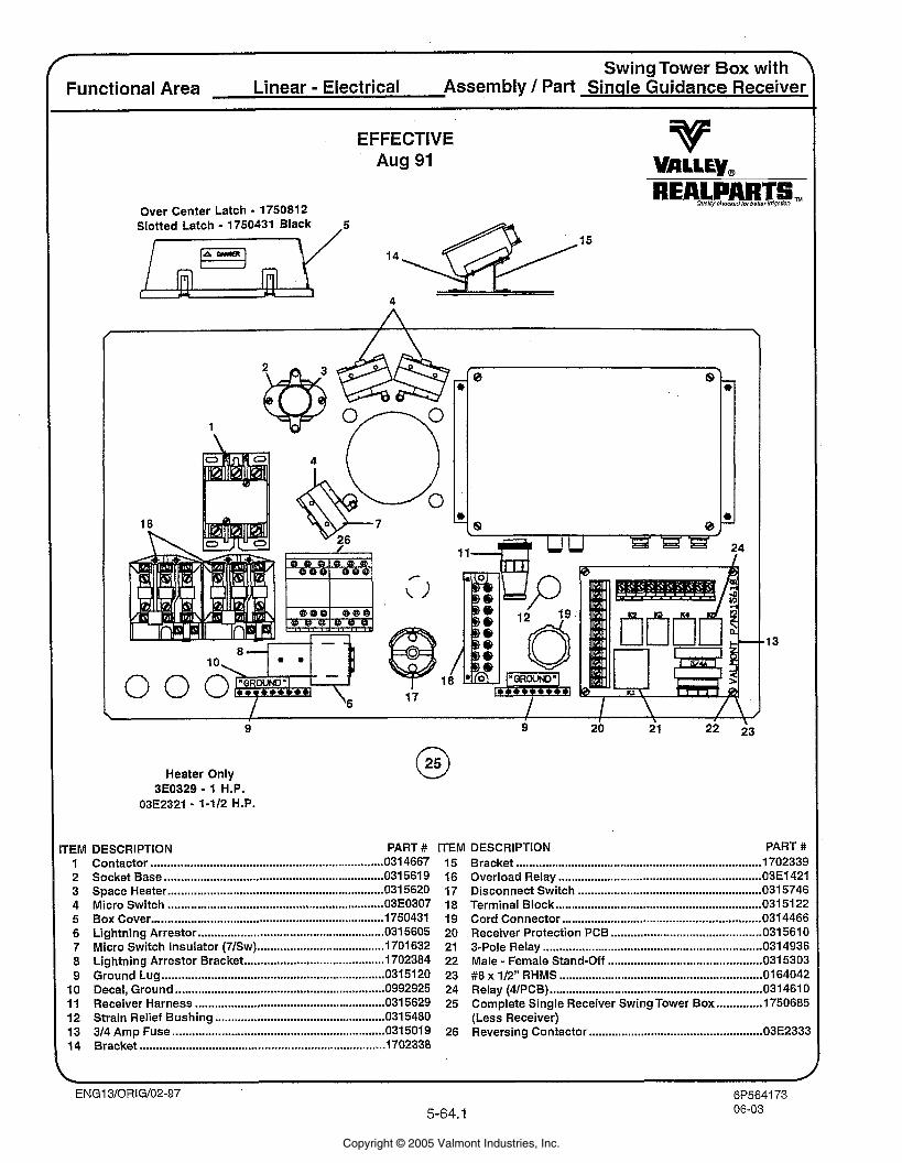
Swing Tower Box with ' Functional Area Linear - Electrical Assembly I Part Sinqle Guidance Receiver
EFFECTIVE Aug 91
Over Center Latch - 1750812 Slotted Latch - 1750431 Black
4
Heater Only 3E0329 - 1 H.P.
03E2321 - 1-112 H.P.
rEM DESCRIPTION PART # ITEM DESCRIPTION PART # 1 Contactor ....................................................................... 0 4667 15 Bracket .......................................................................... 1702339 2 Socket Base ................................................................... 0 5 6 1 9 16 Overload Relay .............................................................. 03E1421 3 Space Heater ............................................................... 0 % 2 0 17 Disconnect Switch .................................................... 0 3 1 5 7 4 E 4 Micro Switch .................................................................. 0 18 Terminal Block ............................................................... 0315122
............................................................. 5 Box Cover .............................................................................. 19 Cord Connector 4 4 6 E 6 Lightning Arrestor .................................................. .......05605 20 Receiver Protection PCB ........................................ 0 561 C 7 Micro Switch Insulator (71Sw) .................................. 7 0 1 632 21 &Pole Relay ................................................................. 0 493E 8 Lightning Arrestor Bracket ........................................... 702384 22 Male . Female Stand-Off .......................... .. ............... 031530: 9 Ground Lug ................................................................... 5 1 2 0 23 #8 x 112" RHMS ............................................................. 0164042
10 Decal, Ground ................................................................ 24 Relay (4lPCB) ............................................................... 031 461 C 11 Receiver Harness .......................................................... 0 5629 25 Complete Single Receiver Swing Tower Box .............. l75068E
.................................................... 12 Strain Relief Bushing 035480 (Less Receiver) ..................................................... 13 314 Amp Fuse ................................................................. 5 0 1 9 26 Reversing Contactor 03E233:
........................................................................... 14 Bracket 17CQ338
Copyright © 2005 Valmont Industries, Inc.
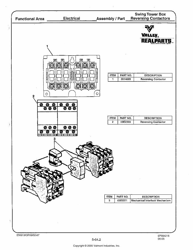
> Swing Tower Box
Functional Area Electrical Assembly 1 Part Reversing Contactors
ITEM I PART NO. I DESCRIPTION 1 1 0314683 1 Reversing Contactor
I ITEM 1 PART NO. I DESCRIPTION I 1 2 1 03E2333 1 Reversing Contactor I
Copyright © 2005 Valmont Industries, Inc.

Copyright © 2005 Valmont Industries, Inc.
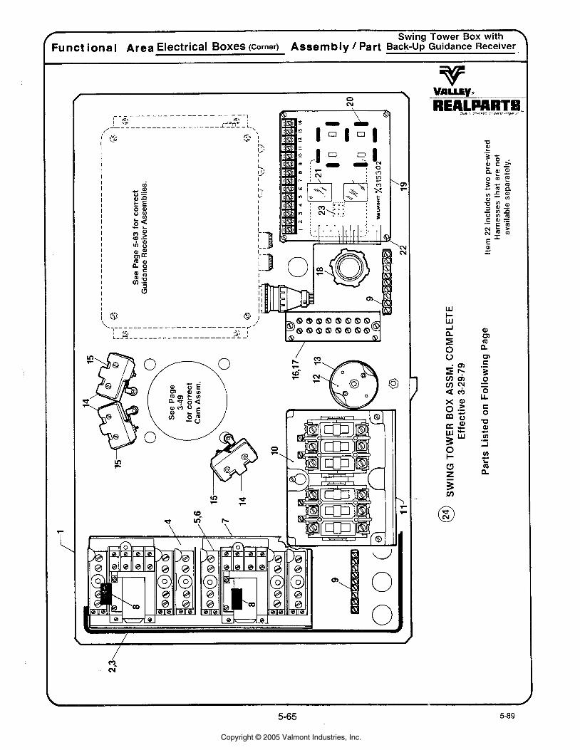
* Swing Tower Box with
Funct ional Area Electrical Boxes (Corner) Assembly / Part Back-up Guidance Receiver
Copyright © 2005 Valmont Industries, Inc.
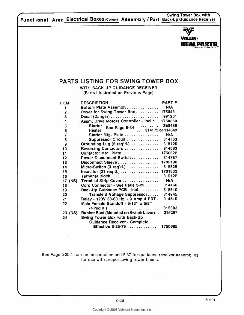
4 Swing Tower Box with Funct ional Area Electrical Boxes (corner) Assembly 1 Part Back-Up Guidance Receiver
PARTS LISTING FOR SWING TOWER BOX WITH BACK UP GUIDANCE RECEIVER
(Parts Illustrated on Previous Page)
ITEM 1 2 3 4 5 6 7 8 9
10 11 12 13 14 15 16 17 (NS) 18 19 20 2 1 22
23 (NS) 24
DESCRIPTION PART # Bottom Plate Assembly. . . . . . . . . . . . . . N/A
. . . . . . . . . . Cover for Swing Tower Box 1750431 . . . . . . . . . . . . . . . . . . . . . Decal (Danger) 991261
Assm. Drive Motors Controller - Incl.: . . 1750350 Starter . . . . . . . . 3E0486 Heater
See Page 5-34 . . 31 41 75 or 31 4349
. . . . . . . . . . . . . . . Starter Mtg. Plate . . . . . . . . . . . . . . Suppressor Circuit
. . . . . . . . . . . . Grounding Lug (2 req'd.) . . . . . . . . . . . . . . . Reversing Contactors
. . . . . . . . . . . . . . . . Contactor Mtg. Plate . . . . . . . . . . Power Disconnect Switch..
. . . . . . . . . . . . . . . . . . Disconnect Sleeve . . . . . . . . . . . . . . Micro-Switch (3 req'd.)
. . . . . . . . . . . . . . . . Insulator (21 req'd.). . . . . . . . . . . . . . . . . . . . Terminal Block..
. . . . . . . . . . . . . . Terminal Strip Cover.. . . . . . . Cord Connector - See Page 5-22
. . . . . . . Back-Up Guidance PCB - Incl.: Transient Voltage Suppressor. . . . .
Relay - 120V 50-60 Hz. - 3 Amp 4 PDT. Male-Female Standoff - 5/16" x 518''
(4 req'd.) . . . . . . . . . . . . . . . . . . . . . . Rubber Boot (Mounted on Switch Lever). . Swing Tower Box with Back-Up
Guidance Receiver - Complete . ............. Effective 3-29-79
See Page 5-35.1 for cam assemblies and 5-37 for guidance receiver assemblies for use with proper swing tower boxes.
Copyright © 2005 Valmont Industries, Inc.
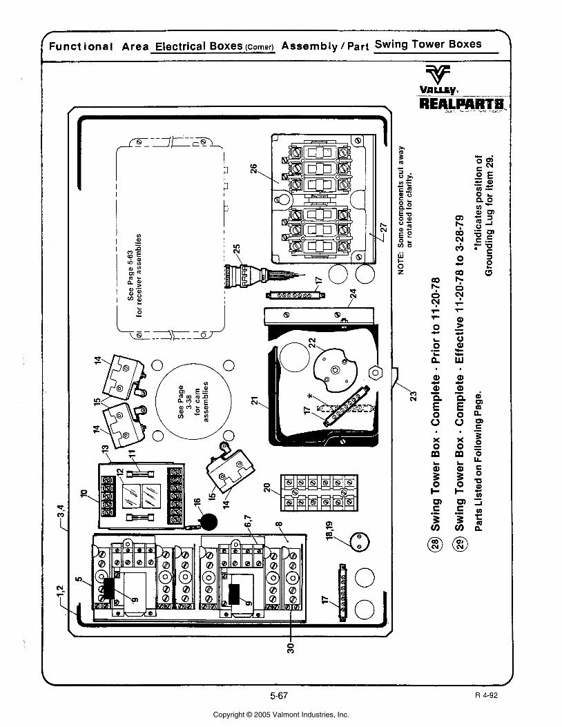
Funct i ona l Area Electrical Boxes (corner) Assembly / Part Swing Tower Boxes
REALM .. .-. .., . .. -r ..
Copyright © 2005 Valmont Industries, Inc.
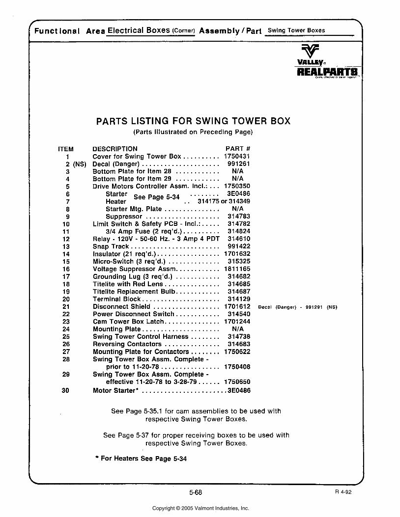
Funct ional Area Electrical Boxes (Corner) Assembly / Part Swing Tower Boxes
ITEM 1 2 (NS) 3 4 5 6 7 8 9
10 11 12 13 14 15 16 17 18 19 20 21 22 23 24 25 26 27 28
29
30
PARTS LISTING FOR SWING TOWER BOX (Parts Illustrated on Preceding Page)
DESCRIPTION PART # . . . . . . . . Cover for Swing Tower Box. . 1750431
Decal (Danger) . . . . . . . . . . . . . . . . . . . . . 991 261 . . . . . . . . . . . . Bottom Plate for Item 28 NIA . . . . . . . . . . . . Bottom Plate for Item 29 NIA
Drive Motors Controller Assm. Incl.: . . . 1750350 . . . . . . . . Starter 3E0486
Heater See Page 5-34 . . 314175 or 314349 . . . . . . . . . . . . . . . Starter Mtg. Plate
. . . . . . . . . . . . . . . . . . . . Suppressor . . . . . Limit Switch & Safety PCB - Incl.:
. . . . . . . . . 314 Amp Fuse (2 req'd.). Relay - 120V - 50-60 Hz. - 3 Amp 4 PDT
. . . . . . . . . . . . . . . . . . . . . . . . SnapTrack . . . . . . . . . . . . . . . . Insulator (21 req'd.).
. . . . . . . . . . . . . . Micro-Switch (3 req'd.) . . . . . . . . . . . Voltage Suppressor Assm.
. . . . . . . . . . . . Grounding Lug (3 req'd.) . . . . . . . . . . . . . . . Titelite with Red Lens
. . . . . . . . . . . Titelite Replacement Bulb. . . . . . . . . . . . . . . . . . . . Terminal Block.. . . . . . . . . . . . . . . . . . . Disconnect Shield
. . . . . . . . . . Power Disconnect Switch.. . . . . . . . . . . . . . Cam Tower Box Latch..
Mounting Plate. . . . . . . . . . . . . . . . . . . . . Swing Tower Control Harness . . . . . . . . Reversing Contactors . . . . . . . . . . . . . . . Mounting Plate for Contactors . . . . . . . . Swing Tower Box Assm. Complete -
prior to 1 1-20-78 . . . . . . . . . . . . . . . . Swing Tower Box Assm. Complete -
effective 11-20-78 to 3-28-79 . . . . . . Motor Starter* ......................
NIA 31 4783 31 4782 31 4824 31 461 0 991 422
1701 632 31 5325
1811165 31 4682 31 4685 31 4687 31 41 29
1701612 Decal (Danger) - 991291 (NS)
31 4540 1701 244
NIA 31 4738 31 4683
1750622
See Page 5-35.1 for cam assemblies to be used with respective Swing Tower Boxes.
See Page 5-37 for proper receiving boxes to be used with respective Swing Tower Boxes.
For Heaters See Page 5-34
Copyright © 2005 Valmont Industries, Inc.
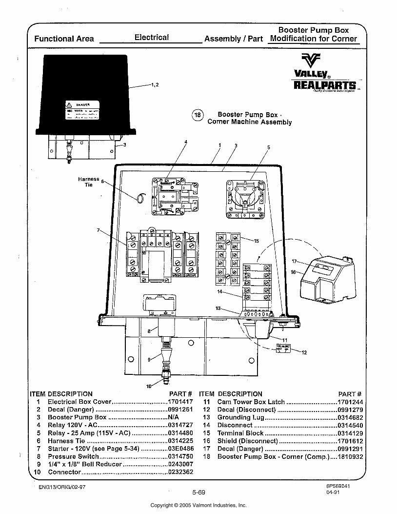
Booster Pump Box Functional Area Electrical Assembly / Part Modification for Corner
v VALLEY, REALPART Ous~chsckadbrbsnerrrdgalion
Booster Pump Box - @ Corner Machine Assembly
Harness Tie 6'
---I. 'I- /'
TEM DESCRIPTION PART # ITEM DESCRIPTION PART # Electrical Box Cover ............................... 170141 7 Decal (Danger) ........................................ 0991261 Booster Pump Box ................................. NIA Relay 120V - AC ....................................... I 4 7 2 7 Relay - 25 Amp (1 15V - AC) .................... 031 4480 Harness Tie ............................................. 0314225 Starter - 120V (see Page 5-34) ............... 03E0486 Pressure Switch ...................................... 0314750 114" x 1/8" Bell Reducer ......................... 0243007 Connector ................................................ 0232362
............................ Cam Tower Box Latch 1701 244 Decal (Disconnect) ................................. 0991 279 Grounding Lug ........................................ 0314682 Disconnect .............................................. 031 4540
........................................ Terminal Block 0314129 Shield (Disconnect) ................................ 1701 612 Decal (Danger) ....................................... 0991 291 Booster Pump Box - Corner (Comp.) .... 181 0932
Copyright © 2005 Valmont Industries, Inc.
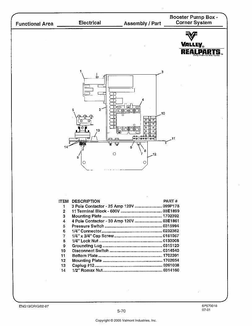
ITEM 1 2 3 4 5 6 7 8 9 10 11 12 13 14
DESCRIPTION PART # 3 Pole Contactor . 25 Amp 120V ........................ 099P178 11 Terminal Block . 600V .................................... 03E1899 Mounting Plate .................................................... 1702392 4 Pole Contactor . 30 Amp 120V ........................ 03E1861 Pressure Switch ................................................ 0315994 114" Connector ................................................... 0232362 114" x 314" Cap Screw .......................................... 01 61 057 114" Lock Nut .................................................... 0133008 Grounding Lug .................................................... 03151 20
.............................................. Disconnect Switch 0314540 Bottom Plate ........................................................ 1702391 Mounting Plate .................................................... 1702054 Caplug #I 2 ........................................................ 0261 008 112" Romax Nut .................................................. 031 41 60
Copyright © 2005 Valmont Industries, Inc.
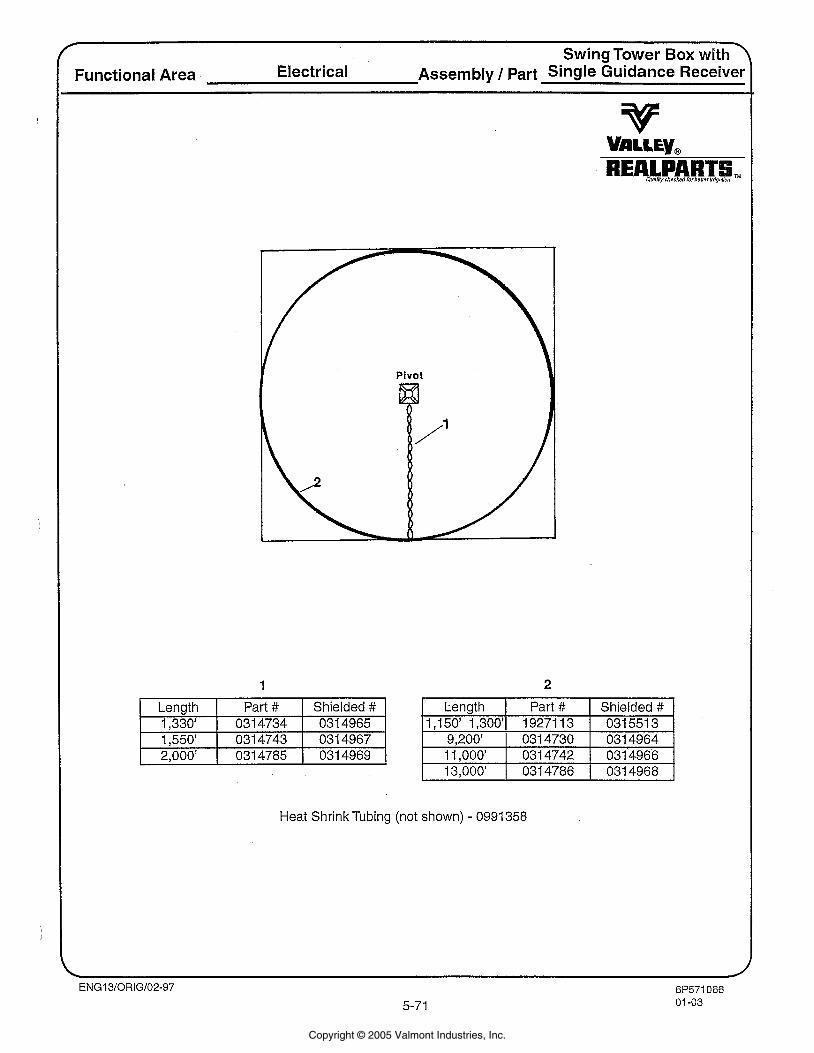
+ Swing Tower Box withy
Functional Area Electrical Assembly / Part Single Guidance Receiver
v V A L ~ E ~ , REALPAR oue~rty chacked /or beflWIr1!11811~
Length Part # Shielded # 1,330' 031 4734 031 4965 1,550' 031 4743 031 4967 9,200' 2,000' 031 4785 031 4969
Heat Shrink Tubing (not shown) - 0991 358
Copyright © 2005 Valmont Industries, Inc.
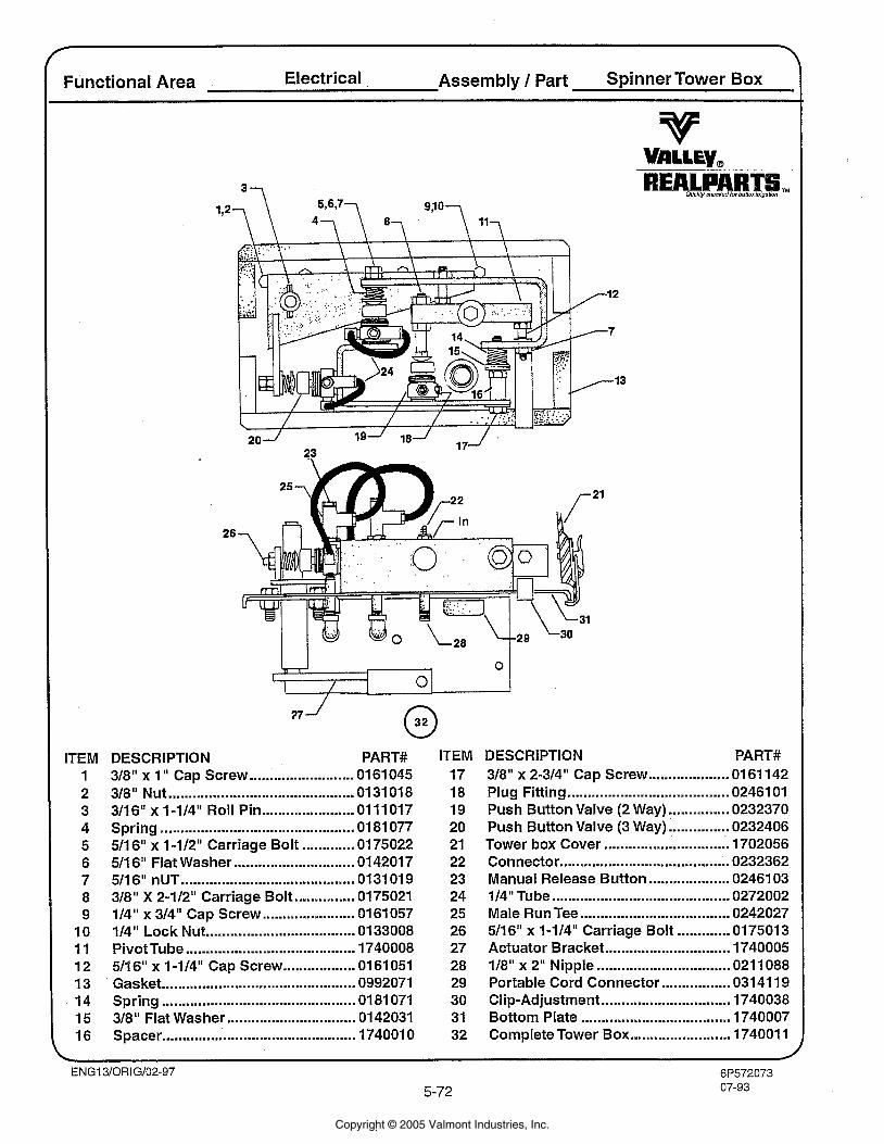
Functional Area Electrical Assembly I Part Spinner Tower Box
ITEM 1 2 3 4 5 6 7 8 9 10 1 1 12 13 14 15 16
DESCRIPTION PART# 318" x 1 " Cap Screw .......................... 01 61 045 318" Nut ............................................. 0131 018 311 6" x 1-114" Roll Pin ....................... 01 11 017 Spring ................................................ 01 81 077 511 6" x 1-112" Carriage Bolt ............. 0175022
.............................. 511 6" Flat Washer 0142017 511 6" nUT .......................................... 0131019 318" X 2-112" Carriage Bolt ............... 0175021 114" x 314" Cap Screw ....................... 01 61 057 114" Lock Nut ..................................... 0133008 Pivot Tube .......................................... 1740008 511 6" x 1-114" Cap Screw .................. 01 61 051 Gasket ............................................. 0992071 Spring ............................................... 01 81 071 318" Flat Washer ................................ 01 42031 Spacer ............................................. 174001 0
ITEM 17 18 19 20 21 22 23 24 25 26 27 28 29 30 3 1 32
DESCRIPTION .................... 318" x 2-314" Cap Screw 01 61 142
........................................ Plug Fitting 02461 01 ............... Push Button Valve (2 Way) 0232370 ............... Push Button Valve (3 Way) 0232406
............................... Tower box Cover 1702056 .......................................... Connector 0232362
.................... Manual Release Button 0246103 ............................................ 114" Tube 0272002
..................................... Male Run Tee 0242027 5/16" x 1-114" Carriage Bolt ............. 0175013
............................... Actuator Bracket 1740005 118" x 2" Nipple ................................. 021 1088
................. Portable Cord Connector 031 41 19 ................................ Clip-Adjustment 1740038
..................................... Bottom Plate 1740007 ......................... Complete Tower Box 174001 1
Copyright © 2005 Valmont Industries, Inc.
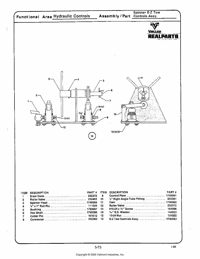
:unct ional Area Hydraulic Controls Assembly Part cbntrols Assy.
v
ITEM DESCRIPTION PART # . . . . . . . . . . . . . . . . . . . . . . . . . . 1 Drain Cock. . 232378
. . . . . . . . . . . . . . . . . . . . . . . . . . . 2 Roller Valve 232405 . . . . . . . . . . . . . . . . . . . . . . . . . 3 Spinner Head. 1740088 . . . . . . . . . . . . . . . . . . . . . . . . 4 %"x1" Roll Pin 11 1024
. . . . . . . . . . . . . . . . . . . . . . . . . . . . . . 5 Bushing 1750587 . . . . . . . . . . . . . . . . . . . . . . . . . . . . . 6 Hexshaft 1740086
. . . . . . . . . . . . . . . . . . . . . . . . . . . 7 Cotter Pin. . 151012 . . . . . . . . . . . . . . . . . . . . . . . . . . . . 8 Connector 232362
ITEM 9
40 11 12 13 14 15 16'
DESCRIPTION PART # . . . . . . . . . . . . . . . . . . . . . . . . . . Control Plate 1740091
. . . . . . . . . . . . . %" Right Angle Tube Fitting 232361 . . . . . . . . . . . . . . . . . . . . . . . . . . . . . . . . . Cam 1740080
. . . . . . . . . . . . . . . . . . . . . . . . . . . Roller Valve 232372 #lo-24 x W" Screw . . . . . . . . . . . . . . . . . . . . . 164096 %a" S.S. Washer. . . . . . . . . . . . . . . . . . . . . . . . 142023 10-24Nut . . . . . . . . . . . . . . . . . . . . . . . . . . . . . 131055 E-Z Tow Controls Assy. . . . . . . . . . . . . . . . . . 1740092
Copyright © 2005 Valmont Industries, Inc.
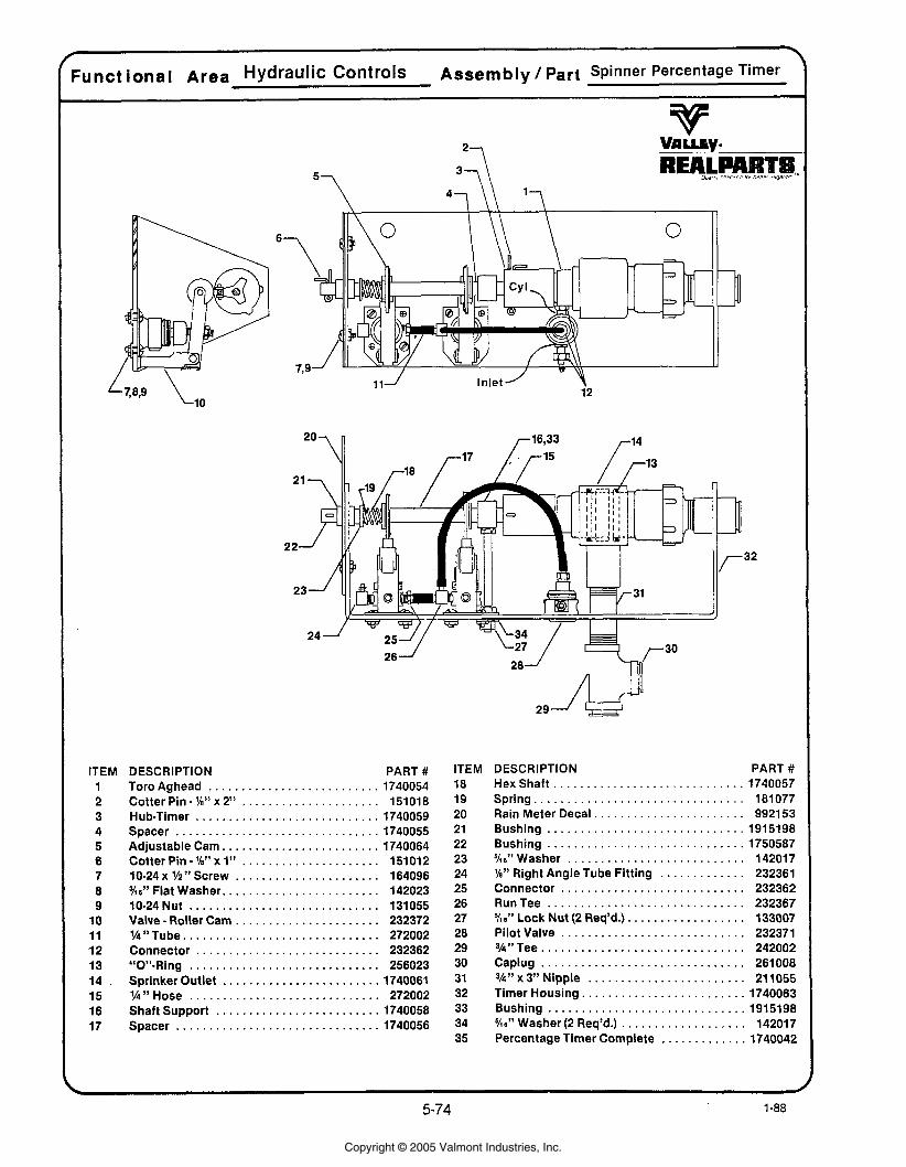
ITEM DESCRIPTION PART # 1 Toro Aghead . . . . . . . . . . . . . . . . . . . . . . . . . . 1740054 2 Cotter Pin . 'la" x 2" . . . . . . . . . . . . . . . . . . . . . 151018 3 Hub-Timer . . . . . . . . . . . . . . . . . . . . . . . . . . . . 1740059 4 Spacer . . . . . . . . . . . . . . . . . . . . . . . . . . . . . . . 1740055 5 Adjustable Cam . . . . . . . . . . . . . . . . . . . . . . . . 1740064 6 Cotter Pin-lh"xl" . . . . . . . . . . . . . . . . . . . . . 151012 7 10-24 x 1/2 " Screw . . . . . . . . . . . . . . . . . . . . . . 164096 8 KO" Flat Washer . . . . . . . . . . . . . . . . . . . . . . . . 142023 9 10-24Nut . . . . . . . . . . . . . . . . . . . . . . . . . . . . . 131055
10 Valve . Roller Cam . . . . . . . . . . . . . . . . . . . . . . 232372 , 11 %"Tube . . . . . . . . . . . . . . . . . . . . . . . . . . . . . . 272002 1 12 Connector . . . . . . . . . . . . . . . . . . . . . . . . . . . . 232362
13 "0"-Ring . . . . . . . . . . . . . . . . . . . . . . . . . . . . . 256023 . . . . . . . . . . . . . . . . . . . . . . . . . i . . . . . . . . . . . . . . . . . . . . . . . . . . . . .
14 Sprinker Outlet 1740061 15 lh " Hose 272002
. . . . . . . . . . . . . . . . . . . . . . . . . 16 Shaft Support 1740058 . . . . . . . . . . . . . . . . . . . . . . . . . . . . . . . I 17 Spacer 1740056
ITEM DESCRIPTION PART # 18 HexShaft . . . . . . . . . . . . . . . . . . . . . . . . . . . . . 1740057 19 Spring . . . . . . . . . . . . . . . . . . . . . . . . . . . . . . . . 181077
. . . . . . . . . . . . . . . . . . . . . . . 20 Rain Meter Decal 992153 21 Bushing . . . . . . . . . . . . . . . . . . . . . . . . . . . . . . 1915198 22 Bushing . . . . . . . . . . . . . . . . . . . . . . . . . . . . . . 1750587 23 %a" Washer . . . . . . . . . . . . . . . . . . . . . . . . . . . 142017 24 %" Right Angle Tube Fitting . . . . . . . . . . . . . 232361 25 Connector . . . . . . . . . . . . . . . . . . . . . . . . . . . . 232362 26 RunTee . . . . . . . . . . . . . . . . . . . . . . . . . . . . . . 232367 27 %a" Lock Nut (2 Req'd.) . . . . . . . . . . . . . . . . . . 133007 28 Pilot Valve . . . . . . . . . . . . . . . . . . . . . . . . . . . . 232371 29 3h"Tee . . . . . . . . . . . . . . . . . . . . . . . . . . . . . . . 242002 30 Caplug . . . . . . . . . . . . . . . . . . . . . . . . . . . . . . . 261008 31 3h" x 3" Nipple . . . . . . . . . . . . . . . . . . . . . . . . 21 1055 32 Timer Housing . . . . . . . . . . . . . . . . . . . . . . . . . 1740063 33 Bushing . . . . . . . . . . . . . . . . . . . . . . . . . . . . . . 1915198 34 %a" Washer (2 Req'd.) . . . . . . . . . . . . . . . . . . . 142017 35 Percentage Timer Complete . . . . . . . . . . . . . 1740042
Copyright © 2005 Valmont Industries, Inc.
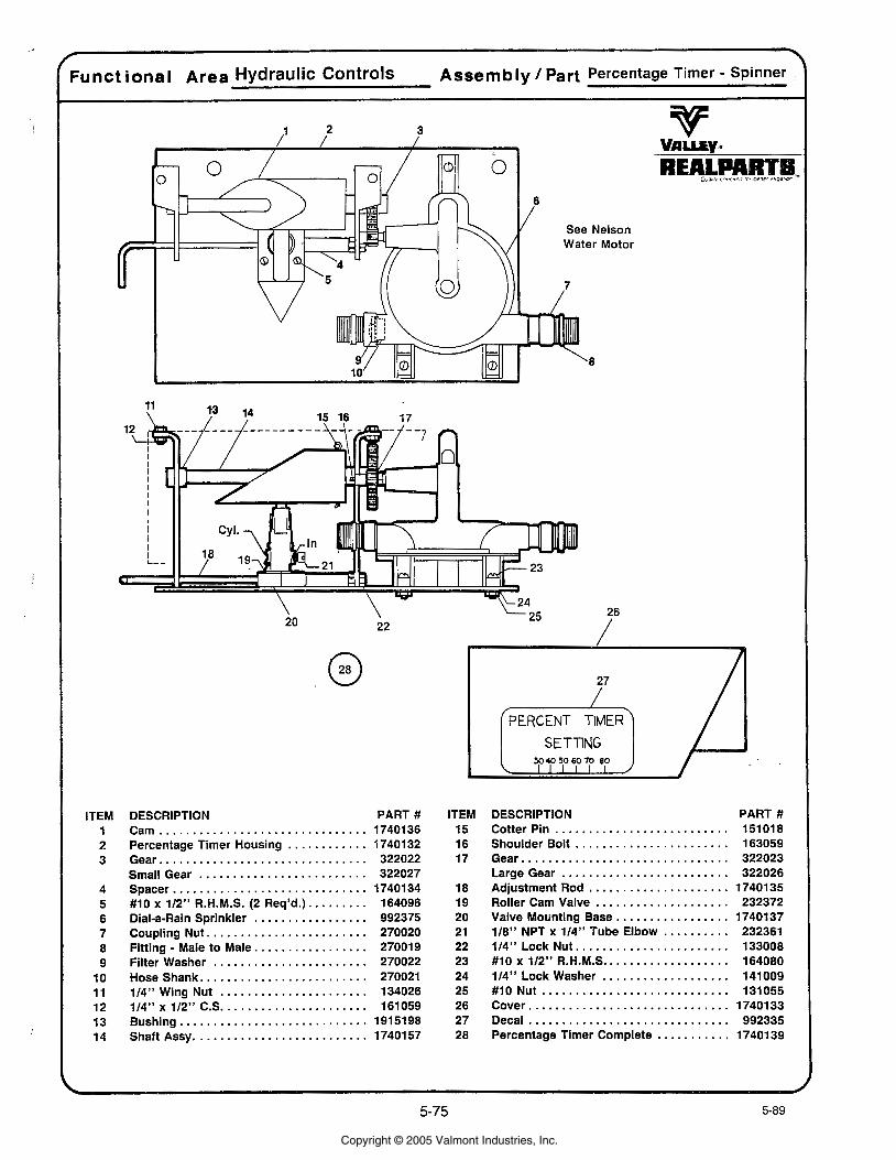
ITEM 1 2 3
4 5 6 7 8 9
10 11 12 13 14
DESCRIPTION PART # ............................... Cam 1740136
............ Percentage Timer Housing 17401 32 ............................... Gear 322022
......................... Small Gear 322027 ............................. Spacer 1740134
......... # I0 x 112" R.H.M.S. (2 Req'd.) 164096 ................. Dial-a-Rain Sprinkler 992375
........................ Coupling Nut 270020 ................. Fitting . Male to Male 270019
....................... Filter Washer 270022 ......................... Hoseshank 270021
...................... 114" Wing Nut 134026
. . . . . . . . . . . . . . . . . . . . . . 114" x 112" C.S 161059 Bushing ............................ 1915198
.......................... Shaft Assy 1740157
ITEM 15 16 17
18 19 20 21 22 23 24 25 26 27 28
DESCRIPTION PART # .......................... Cotter Pin 151 01 8
....................... Shoulder Bolt 163059 ............................... Gear 322023
......................... LargeGear 322026 ..................... Adjustment Rod 1740135 .................... Roller Cam Valve 232372
................. Valve Mounting Base 1740137 .......... 118" NPT x 114" Tube Elbow 232361
....................... 114" Lock Nut 133008 #10x112"R.H.M.S ................... 164080
................... 114" Lock Washer 141009 ............................ #10 Nut 131055
Cover .............................. 1740133 Decal .............................. 992335
........... Percentage Timer Complete 1740139
Copyright © 2005 Valmont Industries, Inc.
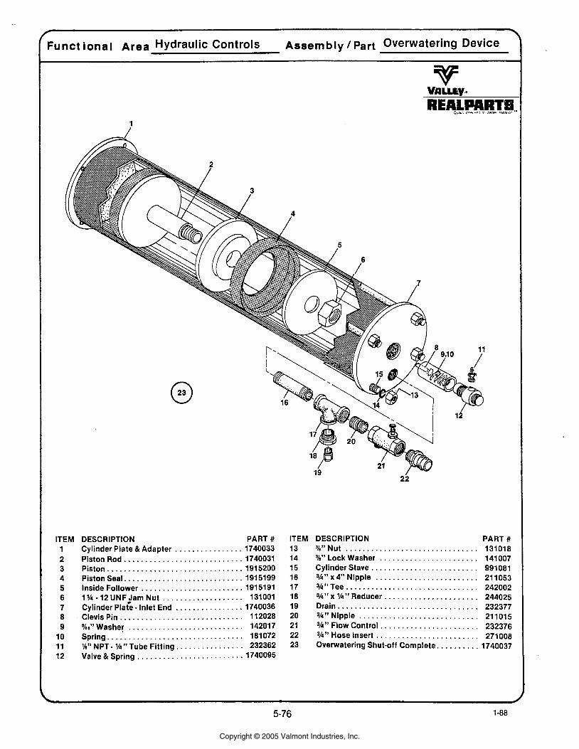
ITEM DESCRIPTION PART # 1 Cylinder Plate &Adapter . . . . . . . . . . . . . . . . 1740033
. . . . . . . . . . . . . . . . . . . . . . . . . . . . 2 Piston Rod 1740031 . . . . . . . . . . . . . . . . . . . . . . . . . . . . . . . . 3 Piston 1915200
. . . . . . . . . . . . . . . . . . . . . . . . . . . . 4 Piston Seal 1915199 . . . . . . . . . . . . . . . . . . . . . . . . 5 Inside Follower 1915191
. . . . . . . . . . . . . . . . . . . . 6 1% 12 UNFjarn Nut 131001 . . . . . . . . . . . . . . . . 7 Cylinder Plate . Inlet End 1740036
. . . . . . . . . . . . . . . . . . . . . . . . . . . . . 8 Clevis Pin 112028 . . . . . . . . . . . . . . . . . . . . . . . . . . . 9 KO" Washer 142017
. . . . . . . . . . . . . . . . . . . . . . . . . . . . . . . . 10 Spring 181072 . . . . . . . . . . . . . . . . 11 'h" NPT . lh" Tube Fitting 232362
. . . . . . . . . . . . . . . . . . . . . . . . . 12 Valve & Spring 1740095
ITEM 13 14 15 16 17 18 19 20 21 22 23
DESCRIPTION PART # . . . . . . . . . . . . . . . . . . . . . . . . . . . . . . . %"Nut 131018
. . . . . . . . . . . . . . . . . . . . . . . SbWLockWasher 141007 Cylinder Stave . . . . . . . . . . . . . . . . . . . . . . . . . 991081 %I" x 4" Nipple . . . . . . . . . . . . . . . . . . . . . . . . 21 1053 %"Tee . . . . . . . . . . . . . . . . . . . . . . . . . . . . . . . 242002 3h" x lh" Reducer . . . . . . . . . . . . . . . . . . . . . . 244025 Drain . . . . . . . . . . . . . . . . . . . . . . . . . . . . . . . . . 232377 3h" Nipple . . . . . . . . . . . . . . . . . . . . . . . . . . . . 211015 3h" Flow Control . . . . . . . . . . . . . . . . . . . . . . . 232376
Hose Insert . . . . . . . . . . . . . . . . . . . . . . . . 271008 Overwatering Shut-off Complete . . . . . . . . . . 1740037
Copyright © 2005 Valmont Industries, Inc.
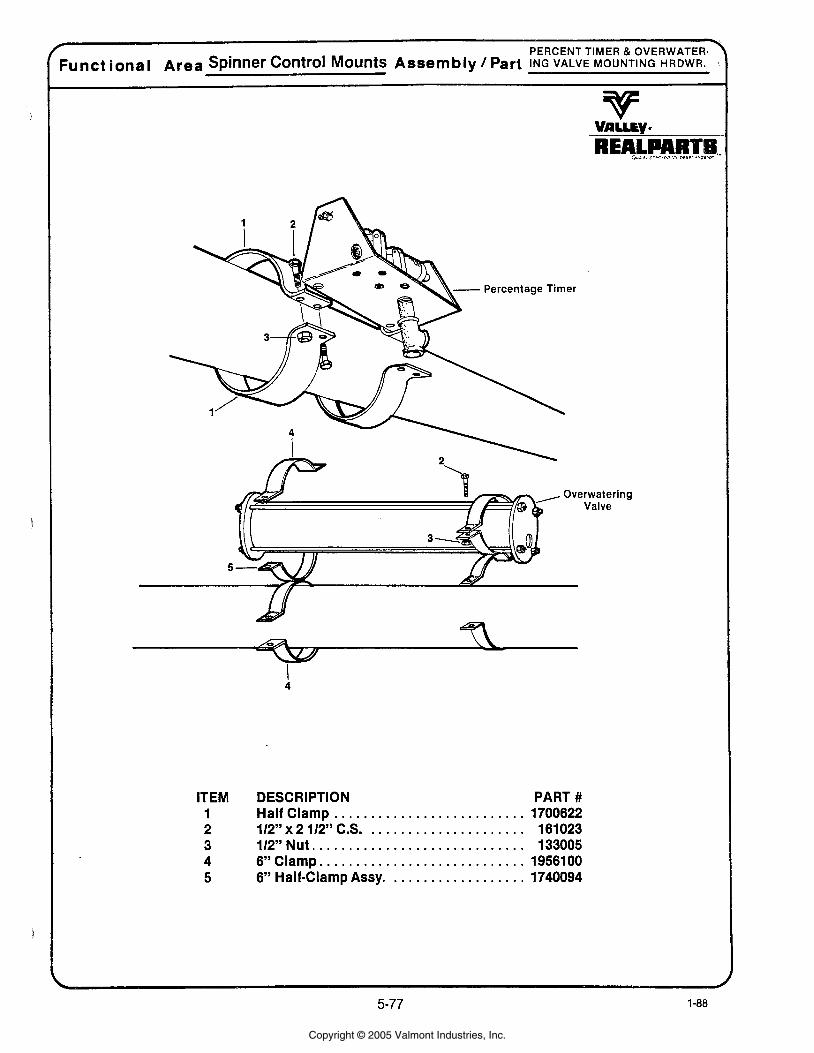
* PERCENT TIMER OVERWATER-\
Funct ional Area Spinner Control Mounts Assembly / Part ING VALVE MOUNTING HRDWR.
Percentage Timer
ITEM DESCRIPTION PART # 1 Half Clamp.. . . . . . . . . . . . . . . . . . . . . . . . . 1700622 2 112" x 2 112" C.S. . . . . . . . . . . . . . . . . . . . . . 161023 3 112"Nut . . . . . . . . . . . . . . . . . . . . . . . . . . . . . 133005 4 6"Clamp . . . . . . . . . . . . . . . . . . . . . . . . . . . . 1956100 5 6" Half-Clamp Assy. . . . . . . . . . . . . . . . . . . 1740094
Copyright © 2005 Valmont Industries, Inc.
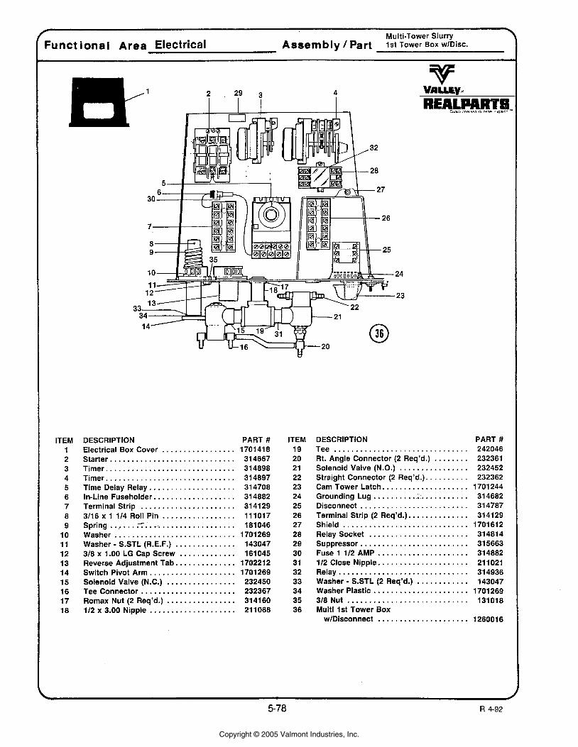
-- r Multi-Tower Slurry 7
Funct ional Area Electrical Assembly / Part 1st Tower BOX wlDisc.
ITEM 1 2 3 4 5 6 7 8 9
10 11 12 13 14 15 16 17 18
DESCRIPTION PART # Electrical Box Cover . . . . . . . . . . . . . . . . . 1701 418 Starter ............................. 314667 Timer .............................. 314898 Timer .............................. 314897 Time Delay Relay. . . . . . . . . . . . . . . . . . . . 314708 In-Line Fuseholder.. . . . . . . . . . . . . . . . . . 314882 Terminal Strip ...................... 314129 3/16 x 1 114 Roll Pin ................. 111017
- ' Spring . . , ........................... 181046 Washer ............................ 1701269 Washer - S.STL (R.E.F.) . ............. 143047 318 x 1 .OO LG Cap Screw ............. 161045 Reverse Adjustment Tab.. ............ 1702212 Switch Pivot Arm.. .................. 1701269 Solenoid Valve (N.C.) ................ 232450 Tee Connector ...................... 232367 Rornax Nut (2 Req'd.) ................ 314160 112 x 3.00 Nipple .................... 21 1068
ITEM DESCRIPTION PART # Tee . . . . . . . . . . . . . . . . . . . . . . . . . . . . . . .
. . . . . . . . Rt. Angle Connector (2 Req'd.) . . . . . . . . . . . . . . . . Solenoid Valve (N.O.)
Straight Connector (2 Req'd.). . . . . . . . . . . . . . . . . . . . . . . . . . . . Cam Tower Latch..
........ . . . . . . . . . . Grounding Lug. . :':. Disconnect . . . . . . . . . . . . . . . . . . . . . . . . .
............. Terminal Strip (2 Req'd.). Shield ............................. Relay Socket .......................
......................... Suppressor Fuse 1 112 AMP ..................... 112 Close Nipple.. . .................. Relay .............................. Washer - S.STL (2 Req'd.) ............
...................... Washer Plastic 318 Nut ............................ Multi 1st Tower Box
wlDisconnect .....................
Copyright © 2005 Valmont Industries, Inc.
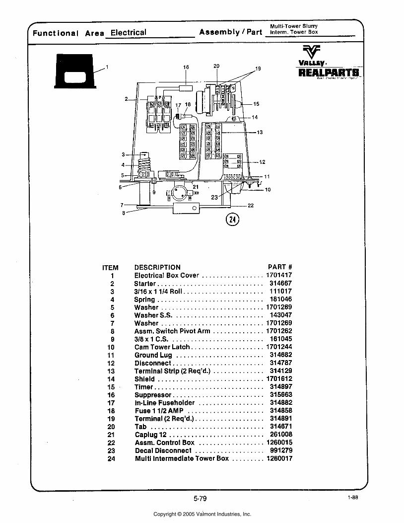
ITEM 1 2 3 4 5 6 7 8 9
10 11 12 13 14 15 16 17 18 19 20 21 22 23 24
DESCRIPTION PART # . . . . . . . . . . . . . . . . . Electrical Box Cover 1701417
Starter . . . . . . . . . . . . . . . . . . . . . . . . . . . . . 314667 . . . . . . . . . . . . . . . . . . . . . . 3116x1 114 Roll 111017
Spring . . . . . . . . . . . . . . . . . . . . . . . . . . . . . 181046 Washer . . . . . . . . . . . . . . . . . . . . . . . . . . . . 1701269 Washer S.S. . . . . . . . . . . . . . . . . . . . . . . . . 143047 Washer . . . . . . . . . . . . . . . . . . . . . . . . . . . . 1701269 Assm . Switch Pivot Arm . . . . . . . . . . . . . . 1701262 318 x 1 C.S. . . . . . . . . . . . . . . . . . . . . . . . . . 161045 Cam Tower Latch . . . . . . . . . . . . . . . . . . . . 1701 244 GroundLug . . . . . . . . . . . . . . . . . . . . . . . . 314682 Disconnect . . . . . . . . . . . . . . . . . . . . . . . . . 314787 Terminal Strip (2 Req'd.) . . . . . . . . . . . . . . 314129 Shield . . . . . . . . . . . . . . . . . . . . . . . . . . . . . 1701612 Timer . . . . . . . . . . . . . . . . . . . . . . . . . . . . . . 314897 Suppressor . . . . . . . . . . . . . . . . . . . . . . . . . 315663 In-Line Fuseholder . . . . . . . . . . . . . . . . . . 314882 Fuse 1 112 AMP . . . . . . . . . . . . . . . . . . . . . 314858 Terminal (2 Req'd.) . . . . . . . . . . . . . . . . . . . 314891 Tab . . . . . . . . . . . . . . . . . . . . . . . . . . . . . . . 314671 Caplug12 . . . . . . . . . . . . . . . . . . . . . . . . . . 261008 Assm . Control Box . . . . . . . . . . . . . . . . . . 126001 5 Decal Disconnect . . . . . . . . . . . . . . . . . . . 991279 Multi Intermediate Tower Box . . . . . . . . . 1260017
Copyright © 2005 Valmont Industries, Inc.

Multi-Tower Slurry Funct ional Area Electrical Assembly 1 Part Last Tower Box
ITEM 1 2 3 4 5 6 7 8 9
10 11 12 13 14 15
DESCRIPTION PART # Electrical Box Cover . . . . . . . . . . . . . . . . . 170141 8
. . . . . . . . . . . . . . . . . . . . . . . . . . . . . Starter 314667 ......................... Suppressor 315663
Timer . . . . . . . . . . . . . . . . . . . . . . . . . . . . . . 314897 ...................... Terminal Strip 314129
Fuse Box ........................... 314177 ........................ Transformer 314890
Assm . Control Box ................... 123001 4 .......................... Connector 232362
...................... Solenoid Valve 232170 ................ Romax Nut (2 Req'd.) 314160
............. Tee Connector (2 Req'd.) 232367 .................... 112x3.00Nipple 211068
.......................... Caplug12 261008 ............................... Tee 242046
ITEM 16 17 18 19 20 21 22 23 24 25 26 27 28 29 30
DESCRIPTION PART # 112 Close Nipple (2 Req'd.) . . . . . . . . . . . . 21 1021
. . . . . . . . . . . . . . 114 x 4.00 Nylon Tubing 272015 ................ . RT Angle Connector 232361
. . . . . . . . . . . . . . . . . . . . . . Solenoid Valve 232450 . . . . . . . . . . . . . . . . . . . . Cam Tower Latch 1701244
Ground Lug ........................ 314682 Disconnect ......................... 314540 Shield ............................. 1701612 112 Fuse AMP ....................... 314858 In-Line Fuseholder ................... 314882 P.B. Relay . . . . . . . . . . . . . . . . . . . . . . . . . . 314610 Snaptrack .......................... 314833 Fuse(5AMP) ....................... 314243
....................... Fuse (3 AMP) 314755 Multi . Last Tower Box ................ 1260018
Copyright © 2005 Valmont Industries, Inc.
Recommended