13-006-676-110000 4-1
Section 4
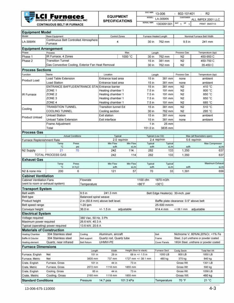
SPECIFICATIONS
4.1 Equipment Specifications ........................................................................................................... 4-3
4.2 Furnace Equipment & Supplied Options ..................................................................................... 4-5
4.3 Computer Equipment ................................................................................................................. 4-7
4.4 Computer Certificate .................................................................................................................. 4-8
4.5 Optiplex 990 ................................................................................................................................ 4-9
4.6 Initial Flowmeter Settings-Low O2 ............................................................................................ 4-11
4.7 Initial Flowmeter Settings–Very Low O2 .................................................................................. 4-12
4.8 Pressure & Flow Characteristics ............................................................................................... 4-13

Section 4
4-2 LA-309 Owner’s Manual
Specifications
13-006-675-110000 4-3
4.1 Equipment Specifications
Section 4
4-4 LA-309 Owner’s Manual

Specifications
13-006-675-110000 4-5
4.2 Furnace Equipment & Supplied Options

Section 4
4-6 LA-309 Owner’s Manual

Specifications
13-006-675-110000 4-7
4.3 Computer Equipment

Section 4
4-8 LA-309 Owner’s Manual
4.4 Computer Certificate

Specifications
13-006-675-110000 4-9
4.5 Optiplex 990

Section 4
4-10 LA-309 Owner’s Manual

Flowmeters (10ppmv) ©LOCHABER CORNWALL, INC.
DOC NBR: 802-101460-01 R0MODEL: DWN: SLB 08/25/11
SERIAL NBR: APVL: JMC 01/25/13Customer: PRINT: PM: JMC 09/26/13
PROCESS GASGAS1 N2 NitrogenGAS2 none none
Replenish Rate is the number of times/minute that the furnace (or a section of the furnace) evacutes its gas
Replenish Rate Furnace or Section Replenishes/Hour Time to Refresh Furnace or Section1 times/minute 60 times/hour 60 seconds2 times/minute 120 times/hour 30 seconds3 times/minute 180 times/hour 20 seconds4 times/minute 240 times/hour 15 seconds
Different sections of the furnace can be replenished at different rates, if requiredFlowmeters graduated in: sL/m (lg=RMC flowmeters, sm=small RMA flowmeters) 2
BALANCE148 scfh difference => Positive pressure in furnace to purge O270 sL/m grad 62.5% incr (decr) of inflows over outflows Flowmeter
Metered SizeNo. Location Label Gas L/m sL/m grad scfh grad sL/m grad1 BESE Entrance barrier ENTRANCE BAFFLE N2 95 7 2 21 102 Z1 Heating chamber 1 ZONE 1 N2 95 55 4 155 733 Z2-4 Heating chamber 1 ZONES 2 - 4 N2 95 58 4 164 774 TTSE Transition tunnel Ed TRANSITION TUNNEL N2 95 8 2 22 105 CACT Cooling section COOLING TUNNEL N2 95 15 2 43 206 HC Heat chamber sides LAMP SEALS N2 95 30 2 84 40
EXHAUST distr % scfh grad sL/m grad7 EEBE Entrance stack ENTRANCE STACK N2 10 50% 3.5 1.78 EETT Transition tunnel TRANSITION TUNNEL STACK N2 10 50% 1.5 0.7
100%
Furnace Balance scfh sL/mGas Inflow to furnace 501.6 236.7
Gas to Eductors 5.1 2.4Total Gas Required 506.7 239.1
- Stack Exhaust Flow 81.7 38.6Net inflow 425 200.6
cu ft LFurnace internal volume 3.8 108.4
Temp PressPROCESS GAS SUPPLY REQUIREMENTS °C psi Gas scfh sL/m
1 Gas 1 All 21 70 N2 506.7 239.12 Gas 2 21 70 none 0.0 0.0
STP = 21C, 1 atm Total 506.7 239.1
SETTINGS FOR LOW O2 (<10 ppmv) THICK FILM PROFILE: SINGLE GAS
1 per Minute
Replenish Rate Flow
Setting
Desired Replenish Rate per Minute
ALL IMPEX 2001 LLC 03Oct13
Initial Flowmeter
Setting
Initial Flowmeter
Setting
FLOWMETER SETTINGS
13-006 -LA-309
1303091301
0
200
400
600
800
1000
0.0 50.0 100.0 150.0 200.0 250.0
Deg
C
LA-306 Temp Model LA-309

Flowmeters (100ppmv) ©LOCHABER CORNWALL, INC.
DOC NBR: 802-101460-02 R0MODEL: DWN: SLB 08/25/11
SERIAL NBR: APVL: JMC 01/25/13Customer: PRINT: PM: JMC 09/26/13
PROCESS GASGAS1 N2 NitrogenGAS2 none none
Replenish Rate is the number of times/minute that the furnace (or a section of the furnace) evacutes its gas
Replenish Rate Furnace or Section Replenishes/Hour Time to Refresh Furnace or Section1 times/minute 60 times/hour 60 seconds2 times/minute 120 times/hour 30 seconds3 times/minute 180 times/hour 20 seconds4 times/minute 240 times/hour 15 seconds
Different sections of the furnace can be replenished at different rates, if requiredFlowmeters graduated in: sL/m (lg=RMC flowmeters, sm=small RMA flowmeters) 2
BALANCE425 scfh difference => Positive pressure in furnace to purge O2201 sL/m grad 179.5% incr (decr) of inflows over outflows Flowmeter
Metered SizeNo. Location Label Gas L/m sL/m grad scfh grad sL/m grad1 BESE Entrance barrier ENTRANCE BAFFLE N2 95 7 1.5 21 102 Z1 Heating chamber 1 ZONE 1 N2 95 55 24 155 733 Z2-4 Heating chamber 1 ZONES 2 - 4 N2 95 58 8 164 774 TTSE Transition tunnel Ed TRANSITION TUNNEL N2 95 8 1.8 22 105 CACT Cooling section COOLING TUNNEL N2 95 15 1.6 43 206 HC Heat chamber sides LAMP SEALS N2 95 30 3.3 84 40
EXHAUST distr % scfh grad sL/m grad7 EEBE Entrance stack ENTRANCE STACK N2 10 70% 3.5 1.78 EETT Transition tunnel TRANSITION TUNNEL STACK N2 10 30% 1.5 0.7
100%
Furnace Balance scfh sL/mGas Inflow to furnace 501.6 236.7
Gas to Eductors 5.1 2.4Total Gas Required 506.7 239.1
- Stack Exhaust Flow 81.7 38.6Net inflow 425 200.6
cu ft LFurnace internal volume 3.8 108.4
Temp PressPROCESS GAS SUPPLY REQUIREMENTS °C psi Gas scfh sL/m
1 Gas 1 All 21 70 N2 506.7 239.12 Gas 2 21 70 none 0.0 0.0
STP = 21C, 1 atm Total 506.7 239.1
SETTINGS FOR VERY LOW O2 (<100 ppmv): SINGLE GAS MODEL
1 per Minute
Replenish Rate Flow
Setting
Desired Replenish Rate per Minute
ALL IMPEX 2001 LLC 03Oct13
Initial Flowmeter
Setting
Initial Flowmeter
Setting
FLOWMETER SETTINGS
13-006 -LA-309
1303091301
0
200
400
600
800
1000
0.0 50.0 100.0 150.0 200.0 250.0
Deg
C
LA-306 Temp Model LA-309

NOTES:PROCESS GAS TO PLENUMS, EDUCTORS, CHAMBERS, BAFFLES & CAWCFor each gas element tested, the flow was varied and the pressure drop determined by temporary installation of a test pressure gage. Pressures were recorded at each flow.
CAWC COOLING WATERFor the water cooling section, all 6 water flowmeters were opened full and the pressure varied from 2-20 psig. Flows were recorded for each flow meter at each pressure setting and then summed for total water flow through the CAWC as a function of inlet pressure.Tests on the CAWC were run as follows:
1) Furnace operating with last zone at approx. 450-460C. CAWC COOLING AIR turned off. Cooling water set to 8 psig. CAWC cooling water varied from 0 to 60 gph (1 gpm). Temperature profiles of the furnace were run at each of 5 Total Water Flow settings. Inlet & outlet water temp recorded
2) Furnace operating with last zone at approx. 450-460C. Cooling water set to 8 psig, Total Water Flow set to 48 gph (8 gph in each of 6 CAWC chambers). CAWC COOLING AIR increased from 0 to 400 scfh. Temperature profiles of the furnace were run at each of 6 water flow settings.
Data suggests the furnace cooling system be operated with 40 to 60 gph Total Water Flow through the CAWC and improve cooling performance by running the CAWC cooling gas at 200-300 SCFH.
APPROVALS DATE TITLE
DWN JMC 6/11/11CHK'D SBARBER 6/15/11 JOB DOCUMENT NUMBER REV
ENGR JMC 6/22/11 STD 802-101470 0REV DESCRIPTION BY DATE PM JMC 7/28/11 SIZE: B PRNT: 11/28/12 SN: ALL SHEET 1 OF 1
IR FURNACEPRESSURE AND FLOW CHARACTERISTICS
675 N ECKHOFF STREET STE DORANGE, CALIFORNIA 92868 USA
(714) 935-0302 www.furnacepros.com
25, 4
0.0
0.1
0.2
0.3
0.4
0.5
0
2
4
6
8
10
12
14
0 25 50 75 100
Pres
sure
, psi
Pres
sure
, Inc
hes H
2O
Flow, SCFH
9" W Furnace Zone Pressure
9"x 30"L 1-Zone
9"x 30"L 2-Zone
31, 1.6
0
50
100
150
200
250
300
350
0.0
2.0
4.0
6.0
8.0
10.0
12.0
14.0
0 10 20 30 40 50 60 70 80 90 100
Pres
sure
, Inc
hes H
2O
Pres
sure
, psi
Flow, SCFH
Eductor Pressure
48, 5.8
0.0
0.5
1.0
1.5
2.0
0
10
20
30
40
50
60
0 50 100 150 200
Pres
sure
, psi
Pres
sure
, inc
hes H
2O
Flow, SCFH
15"L Baffle Pressure
0
5
10
15
20
25
0 100 200 300 400 500 600 7000
100
200
300
400
500
600
700
Gas
Pre
ssur
e, p
si
Gas Flow, SCFH
Gas
Pre
ssur
e, in
H2O
Cooling System Gas Pressure
3-30" Modules
1-30" Module
0.0
0.2
0.4
0.6
0.8
1.0
1.2
1.4
1.6
1.8
0
5
10
15
20
25
30
35
40
45
50
0 100 200 300 400
Pres
sure
, psi
Pres
sure
, inc
hes H
2O
Flow, SCFH
Plenum Pressure
1-Chamber (est)
2-Chamber (est)
4-Chamber
0
50
100
150
200
250
0 2 4 6 8 10 12 14 16 18 20
Tota
l Wat
er F
low
, gph
Water Supply Pressure, psi
CAWC Water Flow with Varied Supply Pressure
3-30" Module1-30" Module
Section 4
4-14 LA-309 Owner’s Manual
Recommended