Caltrain Standard Specifications
20710-1 September 30, 2011 FLASH BUTT RAIL WELDING
SECTION 20710
FLASH BUTT RAIL WELDING
PART 1 – GENERAL
1.01 DESCRIPTION
A. Section includes specification for welding rails together to Continuous Welded Rail
(CWR) strings by the electric flash butt weld process. Rail within turnouts or
elsewhere as approved by the Engineer may be thermite field welds in accordance
with Section 20720, Thermite Rail Welding.
B. Refer to Sections 20400, Track Construction; 20150, Rail, and 20720, Thermite Rail
Welding, for additional requirements.
1.02 REFERENCE STANDARDS
A. American Railway Engineering and Maintenance of Way Association (AREMA):
1. Manual for Railway Engineering, Volume 1, Chapter 4, Rail
B. American Society for Testing and Materials (ASTM International):
1. E10 Test Method for Brinell Hardness of Metallic Materials
2. E94 Guide for Radiographic Examination
3. E164 Practice for Ultrasonic Contact Examination of Weldments
4. E709 Guide for Magnetic Particle Examination
C. Federal Railroad Administration (FRA):
1. CFR 49 Part 213 Track Safety Standards
2. CFR 49 Part 214, Subpart D Regulations, Roadway Maintenance
Machine Safety
1.03 SUBMITTALS
A. Submit the following welding equipment and procedures to the Engineer for
approval:
1. Work program and schedules for electric flash butt rail welding.
2. Working and laying out drawings, manufacturer's catalog, performance data
and detailed specifications of the equipment to be used for rail welding and
handling. Include lists and details of equipment or welding plant for the
electric flash butt welds.
3. Welding procedure qualification.
Caltrain Standard Specifications
20710-2 September 30, 2011 FLASH BUTT RAIL WELDING
4. Written description of welding ability, including facilities, personnel
qualifications and a list of completed projects similar in scope.
5. Procedures for pulling and aligning the rail, allowances for destressing, and
procedures for bolt holes.
6. Details of proposed equipment and procedure proposed for straightening
welds, if required, including reference data of successful use on previous
projects.
7. Proposed facility for storing CWR.
B. Submit detailed description of testing program and procedures to be performed by
Inspection and Testing Agency (ITA). Submit a copy of the agreement between the
Contractor and ITA at least 30 days before initiating welding operations. Refer to
Section 01400, Quality Control and Assurance, for submittal of proposed ITA.
C. Submit the following reports:
1. Brush recorder charts for each electric-flash butt weld.
3. Daily summary reports of production rail welding inspection and testing.
3. Summary CWR strings.
4. Record on each CWR string installed.
1.04 QUALITY ASSURANCE
A. The agreement between Contractor and ITA shall specify the following:
1. ITA shall submit all original test results directly to the Engineer.
2. ITA shall promptly provide copies of all correspondence between ITA and
the Contractor to the Engineer.
3. The agreement shall run for the duration of the Contract, except as
otherwise agreed to by the Engineer.
4. Test reports to the Engineer to allow for 7 days review and appropriate
action by the Engineer prior to being eligible for payment.
B. Regulatory Requirements: Perform work in accordance with CFR 49 Part 213.
PART 2 – PRODUCTS
2.01 MATERIALS
A. Weld Owner-furnished or Contractor-furnished rail strings into CWR in accordance
with this Section.
B. Provide all incidental materials required to complete the work of this Section.
Caltrain Standard Specifications
20710-3 September 30, 2011 FLASH BUTT RAIL WELDING
PART 3 – EXECUTION
3.01 RAIL STORAGE AND HANDLING
A. Equipment and methods to handle and store CWR strings shall conform to the
requirements of AREMA Manual, Chapter 5, Section 5.2.3, “Handling and
Transporting Continuous Welded Rail (CWR).”
B. Do not use any methods that are likely to cause scratching, notching, rubbing,
scoring, or striking of the rails.
C. Support CWR strings off the ground and space them such that the load on the
supporting ground will not exceed 1,500 pounds per square foot.
D. Store CWR at locations shown on the Contract Drawings or where designated by the
Engineer.
3.02 RAIL WELDING
A. Weld rail by the electric-flash butt welding process. Welding shall conform to AREMA
Manual, Chapter 4, Section 3.11, Specifications for Fabrication of Continuous Welded
Rail, as applicable, except as modified or appended in this Section. All production
welding shall use procedures specified in this Section.
B. Each welding machine shall be equipped with a brush recorder to produce charts
showing traces of electrical impulses and movable platen travel. Submit chart to the
Engineer for each weld. If the chart indicates performance which is not in
conformance with the approved standards, the weld will be rejected.
C. Refer to Section 01590, Temporary Facilities. Furnish all mobile electric power and
utilities required.
D. CWR Strings:
1. String lengths of CWR shall be in lengths as required to install a single piece
of rail meeting the length of the stage of construction or other lengths
approved by the Engineer.
2. Paint string number and length with an aluminum paint on both sides of the
web of the rail at each end of each string.
3. Weld rails so that Heat Number appears on the same side in each string.
4. Do not weld within 8 inches from a bolt hole.
E. Rail Straightening and Cutting Back:
1. Field align or cut back rail ends not meeting the requirements of AREMA:
Chapter 4, Section 3.11, Specifications for Fabrication of CWR.
2. When rail ends cannot be straightened or cut back to achieve the required
rail end tolerance, rail will be rejected.
Caltrain Standard Specifications
20710-4 September 30, 2011 FLASH BUTT RAIL WELDING
3. Mark rejected rail and stockpile in an on-site area designated by the
Engineer.
F. Cutting and Cropping of Rail:
1. Cut clean and square all rails cut prior to welding by means of rail saws or
abrasive cutting disks in accordance with AREMA Manual, Chapter 4, Section
2.1, Specifications for Steel Rails. Do not torch cut rail.
2. Crop or cut rails with bolt holes or thermite welds within 2 feet of a weld at
least 8 inches behind the bolt hole or thermite weld. If the rail is bent, cut
back the rail an additional amount to remove the bend.
3. The small, scrap sections of cropped rail shall become the property of the
Contractor and shall be disposed of off-site.
4. After cutting back the rail, slide back the next rail to make ready for the next
weld or joint.
5. Close gaps generated during sliding back the next rail by installing a plug of
owner-furnished rail.
6. Plugs used to fill the gaps shall be at least 15 feet in length on tangent and
30 feet in length on curved track. Similarly, no rail left in track shall deviate
from this requirement.
7. Prior to placing track back into service at the end of each shift, fully spike,
bolt, and anchor the rail according to the requirements in FRA Class 4 track.
G. Rail End Preparation:
1. Clean the rails free of grease, oil, dirt, scale and moisture to a minimum of 6
inches back from the rail ends, including the rail end surfaces.
2. Grind rail areas in contact with electrodes to remove mill scale and raised
lettering.
3. Align the faces of the rail ends. Divide any difference in the width of the rail
heads equally on both sides of the head.
4. Align vertically for a flat running surface. Any difference of height of the rail
shall be made in the base.
5. Align horizontally so that any variance in width of the 2 rail heads is split
equally between gauge and field side, providing the misalignment along the
gauge line does not exceed 0.040 inch. Additional variance shall be
apportioned to the field side of the weld.
6. Rail ends shall be square and smooth, and shall show no steel defects, dents
or porosity before welding.
Caltrain Standard Specifications
20710-5 September 30, 2011 FLASH BUTT RAIL WELDING
H. If more than 300 LF of rail is welded into CWR, destress the length so fabricated
and 300 feet of rail in both directions beyond.
I. Conform to the requirements of Section 20400, Track Construction for adjusting
and destressing rail in track when rail is pulled.
3.03 WELD QUALITY
A. Each weld shall have full penetration and complete fusion and shall be free of cracks.
B. Small porosity and slag inclusion which show on radiographic film will be accepted if
the total area of internal defects does not exceed 0.09 square inch and the largest
single defect does not exceed 0.180 inch in diameter.
3.04 WELDING PROCEDURE QUALIFICATIONS
A. Prior to beginning of production welding, make three (3) test welds on each welding
machine using the same welding procedure that will be used in production welding.
Each test weld shall join two (2) pieces of rail 18 inches in length.
B. Inspection of welding procedures and testing of welds shall be performed by the ITA
employed by the Contractor.
C. Test each test weld radiographically with a minimum of 4 exposures: One through
the head, one through the web, and one through each of the 2 flanges. Perform
radiography in accordance with ASTM E142. Radiographic film shall be Type 1 or
Type 2. Exposed film density shall be within the range of 1.5 to 3.8.
D. Magnetic particle test each test weld by the coil method (longitudinal magnetization)
using the dry powder method in accordance with ASTM E709.
E. Ultrasonically test each test weld in accordance with ASTM E164. Use equipment
capable of detecting a 3/64-inch discontinuity, 6-1/2 inches below top of rail.
F. Test each test weld for hardness in accordance with ASTM E10. Perform this test on
the head of the rail in the center of the weld. The hardness of the weld shall be
equal to the average Brinell hardness of the two (2) parent rails joined with a
permissible variance of 20 Brinell points.
G. Acceptance will be based on the weld quality requirements stated above.
3.05 WELD NUMBERING
A. Mark a sequential weld number on the rail immediately adjacent to the weld using a
quality aluminum paint marker at the time the weld is made.
B. Number welds sequentially in the order in which they are made.
C. Obtain the initial weld number from the Engineer.
D. When defective welds are replaced, assign a new sequential number to the new weld
by adding a letter to the defective weld number. (e.g. defective weld 109 will be
replaced by 109A)
Caltrain Standard Specifications
20710-6 September 30, 2011 FLASH BUTT RAIL WELDING
3.06 FINISHING THE WELDS
A. Finish weld with a rail mounted profile grinder specifically designed for the work.
Finishing shall conform to the following tolerances:
1. Top of rail head: Plus 0.010 inch to minus 0 inch of the parent rail section.
2. Sides of rail head: Plus or minus 0.010 inch of parent rail section.
B. Finish the balance of the rail section with a hand-held grinder as required to remove
notches, protrusions, gouges, visible cracks and other defects. All grinding shall
blend to the parent rail section and shall not overheat the steel. Complete heavy
grinding while the steel is still hot from welding.
3.07 INSPECTION AND TESTING OF PLANT WELDING
A. The ITA shall perform and report all inspection and testing of production welding as
specified herein within 24 hours of making the welds. Keep the Engineer informed
regarding testing of production welds so that the Engineer may observe inspection
and testing.
B. Visually and dimensionally inspect each weld to determine conformance with the
alignment and finishing tolerances in AREMA Manual, Chapter 4, Section 3.11,
Specifications for Fabrication of Continuous Welded Rail. Cut out and re-weld out-of-
tolerance welds in accordance with this Section.
C. ITA shall magnetic particle test each weld by the coil method (longitudinal
magnetization) using the dry powder method in accordance with ASTM E709. Cut
out and re-weld welds giving fault indications in accordance with this Section.
D. Ultrasonically test each weld for defects in accordance with ASTM E164. Use testing
equipment capable of detecting a 3/64-inch discontinuity, 6-1/2 inches below top of
rail. Perform ultrasonic testing after rail has been destressed.
E. Inspect each weld using a 3-foot straightedge along the centerline of the rail and
0.625 inch below top of rail on the gauge side of the rail head. Center the
straightedge over the weld; the gap between the straightedge and the rail shall
comply with the requirements of AREMA Manual, Chapter 4.
F. Submit to the Engineer a daily summary of results of all testing for each weld on a
form containing the following information:
1. Date and shift
2. Inspector's and welding foreman's name
3. Weld number
4. Result of magnetic particle test
5. Result of ultrasonic test
Caltrain Standard Specifications
20710-7 September 30, 2011 FLASH BUTT RAIL WELDING
6. Note of any dimensional tolerance or other rejections
7. Certification of acceptance or rejection of weld
G. Submit a summary of CWR strings produced, including the following information:
1. String number
2. Lead Rail heat, ingot and letter
3. End Rail heat, ingot and letter
4. String length
5. String temperature at the time of measurement of length
H. For every rail string installed, record on a form provided in this Section the unique
string number assigned to the string, the rail manufacturer of each individual
segment of rail that makes up the string, the month and year date that each
individual segment of rail was rolled, the length of each individual segment of rail
that makes up the string, and the location of each numbered weld that connects each
individual segment of rail in the entire string (i.e. Begin String 145, CF&I 04/96 33’,
Weld 1, PST 10/91 30’, Weld 2 etc….End String 145). The form shall also indicate
the stationing where the “Begin String” portion of the string is installed and the
stationing of where the “End String” portion of the string is installed, the track
number, east/west rail it was intalled on (i.e. Being String 145 Sta 1000+10, End
String 1010+00, MT-1, east rail).
3.08 REPAIR OF DEFECTIVE WELDS
A. Cut out and re-weld all welds rejected during inspection or testing.
B. Crop rails 6 inches from the center of the defective weld prior to rewelding.
3.09 FIELD QUALITY CONTROL
A. The Engineer may randomly select any welds and request to be retested at any time
within the period of the Contract. Replace any defective welds.
B. Prior to completion of welding operation, visually inspect all welds to verify the base
riser break off area has been smoothed. Smooth areas which have not been
smoothed.
3.10 CLEAN UP
A. Inspect areas where welding operation performed. Collect and dispose any
remaining scrap sections of cropped rail daily after completion of welding operation.
ATTACHMENT FOLLOWS
Caltrain Standard Specifications
20710-8 September 30, 2011 FLASH BUTT WELDING
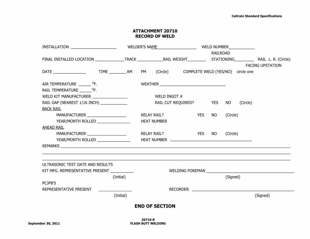
ATTACHMENT 20710
RECORD OF WELD
INSTALLATION WELDER’S NAME WELD NUMBER
RAILROAD
FINAL INSTALLED LOCATION TRACK RAIL WEIGHT STATIONING RAIL L. R. (Circle)
FACING UPSTATION
DATE TIME AM PM (Circle) COMPLETE WELD (YES/NO) circle one
AIR TEMPERATURE OF. WEATHER
RAIL TEMPERATURE OF.
WELD KIT MANUFACTURER WELD INGOT #
RAIL GAP (NEAREST 1/16 INCH) RAIL CUT REQUIRED? YES NO (Circle)
BACK RAIL
MANUFACTURER RELAY RAIL? YES NO (Circle)
YEAR/MONTH ROLLED HEAT NUMBER
AHEAD RAIL
MANUFACTURER RELAY RAIL? YES NO (Circle)
YEAR/MONTH ROLLED HEAT NUMBER
REMARKS
ULTRASONIC TEST DATE AND RESULTS
KIT MFG. REPRESENTATIVE PRESENT WELDING FOREMAN
(Initial) (Signed)
PCJPB’S
REPRESENTATIVE PRESENT RECORDER
(Initial) (Signed)
END OF SECTION
Recommended