Pixus Technologies CatalogPixus Technologies Catalog
www.pixustechnologies.com | [email protected] | US: 916.524.8242 | CAN: 519.885.5775
Kaparel, Ripac, & Vario Brand Products
The Power of Embedded Ingenuity

CompactPCI PCB Front Panels & Injector/Extractor Handles
Product Diversity Knowledge Transfer MPS Expertise Globalization Integrative Thinking
Package Your Electronics With RipacWhen it comes to electronics, no one handles today’sdemanding applications better than Kaparel/Rittal Ripachandles, front panels and accessories. Take our handles for instance. Kaparel/Rittal offers a wide range of types, including the CompactPCI specifiedself-locking injector/extractor handle for high pin countapplications and the Type VII flush profile Telecom handlefor limited I/O. What’s more is we can provide advancedfeatures, such as front panel and ESD protection, amicroswitch for full hot swap applications, keying with4096 combinations and drive chassis. Add to that a wholeline of 3U/6U EMC and Non-EMC front panels and yourpackage is complete – more solutions from The OriginalCompactPCI Company.
96
Section 2_52-103 4/6/04 4:38 PM Page 45
98
Perfect Handling Solutions With
CompactPCI Handles n
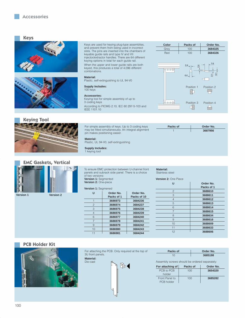
Injector/extractor handle for insertion and removalof connectors with a large number of pins. Thishandle was specifically designed for use in telecom applications.Only for use in conjunction with front horizontalrails with a 10 mm extension (see page 174).
Optionally with 1/2 HP offset PCB attachment,e.g. for component mounting on both sides
Minimum space requirements, thanks to fold-up handle
Option of installing keys (when using keyableguide rails)
Optional integral microswitch for “live insertion”applications
ESD pin to dissipate static charges prior tomaking contact with the connectors and precisepositioning of the board type plug-in unit
Large labeling area on the front
Optimum leverage for connectors with a largenumber of pins
Type VII Injector/Extractor Handle, Plastic (Typically Used For cPCI PSUs)Handles Without Offset
Installation Packs of Order No.Top 1 3688784
Bottom 1 3688785
Material:Plastic
Supply Includes:injector/extractor handle, assembly parts
Accessories:Keys, see page 100Keyable guide rails, see page 57Keyable guide rails with 1/2HP offset, see page 57Microswitch, see page 99
Handles With 1/2HP OffsetInstallation Packs of Order No.
Top 1 3688780Bottom 1 3688781
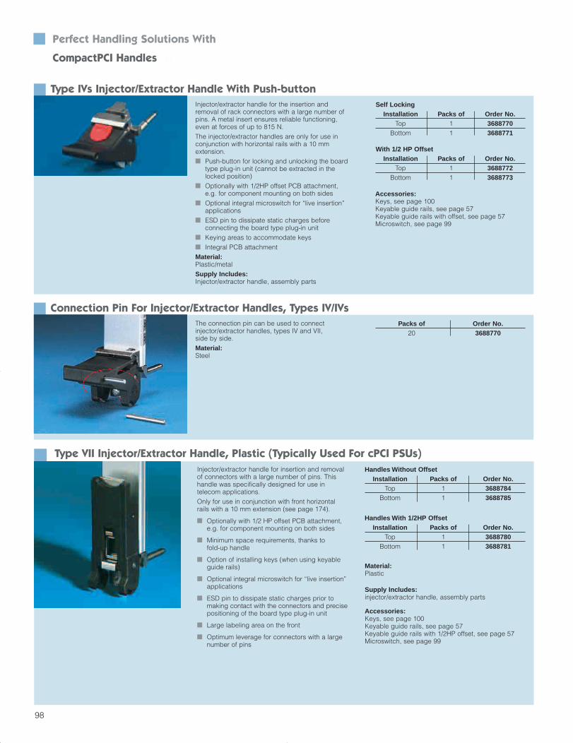
Type IVs Injector/Extractor Handle With Push-buttonInjector/extractor handle for the insertion andremoval of rack connectors with a large number ofpins. A metal insert ensures reliable functioning,even at forces of up to 815 N.The injector/extractor handles are only for use inconjunction with horizontal rails with a 10 mm extension. Push-button for locking and unlocking the board
type plug-in unit (cannot be extracted in thelocked position)
Optionally with 1/2HP offset PCB attachment,e.g. for component mounting on both sides
Optional integral microswitch for “live insertion”applications
ESD pin to dissipate static charges before connecting the board type plug-in unit
Keying areas to accommodate keys Integral PCB attachmentMaterial:Plastic/metalSupply Includes:Injector/extractor handle, assembly parts
Self Locking Installation Packs of Order No.
Top 1 3688770Bottom 1 3688771
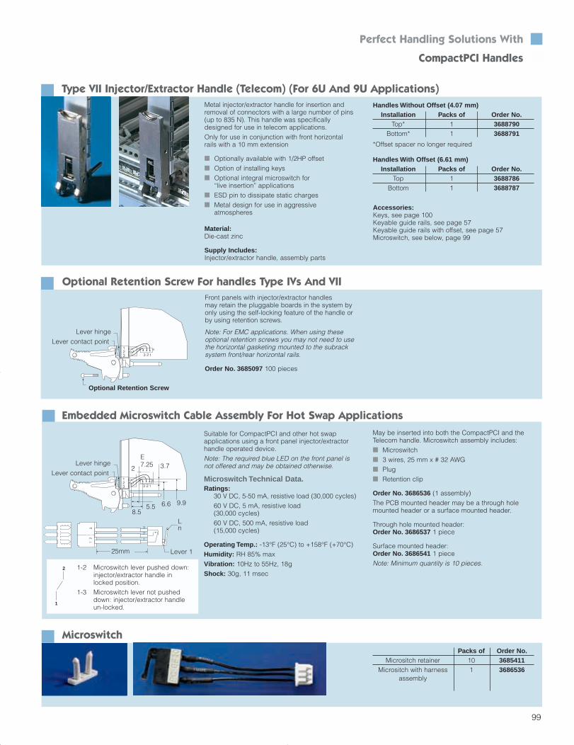
Connection Pin For Injector/Extractor Handles, Types IV/IVsThe connection pin can be used to connect injector/extractor handles, types IV and VII, side by side.Material:Steel
Packs of Order No.20 3688770
With 1/2 HP OffsetInstallation Packs of Order No.
Top 1 3688772Bottom 1 3688773
Accessories:Keys, see page 100Keyable guide rails, see page 57Keyable guide rails with offset, see page 57Microswitch, see page 99
Section 2_52-103 4/6/04 4:38 PM Page 47
99
13
123 2
Levernot pushed d
Lever Hinge
12
3
~25mm
3
2
1
Front panels with injector/extractor handles may retain the pluggable boards in the system byonly using the self-locking feature of the handle orby using retention screws.
Note: For EMC applications. When using these optional retention screws you may not need to usethe horizontal gasketing mounted to the subracksystem front/rear horizontal rails.
Order No. 3685097 100 pieces
Lever 125mm
Suitable for CompactPCI and other hot swap applications using a front panel injector/extractorhandle operated device.Note: The required blue LED on the front panel isnot offered and may be obtained otherwise.
Microswitch Technical Data.Ratings:
30 V DC, 5-50 mA, resistive load (30,000 cycles)60 V DC, 5 mA, resistive load (30,000 cycles)60 V DC, 500 mA, resistive load (15,000 cycles)
Operating Temp.: -13°F (25°C) to +158°F (+70°C)Humidity: RH 85% maxVibration: 10Hz to 55Hz, 18gShock: 30g, 11 msec
May be inserted into both the CompactPCI and theTelecom handle. Microswitch assembly includes: Microswitch 3 wires, 25 mm x # 32 AWG Plug Retention clip
Order No. 3686536 (1 assembly)The PCB mounted header may be a through holemounted header or a surface mounted header.
Through hole mounted header: Order No. 3686537 1 piece
Surface mounted header: Order No. 3686541 1 pieceNote: Minimum quantity is 10 pieces.
1-2 Microswitch lever pushed down:injector/extractor handle in locked position.
1-3 Microswitch lever not pusheddown: injector/extractor handle un-locked.
2
1
Lever hinge
123
123
Lever hinge
8.55.5 6.6 9.9
2
E7.25 3.7
Ln
Embedded Microswitch Cable Assembly For Hot Swap Applications
Optional Retention Screw For handles Type IVs And VII
Lever contact point
Lever contact point
Optional Retention Screw
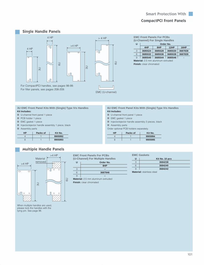
Metal injector/extractor handle for insertion andremoval of connectors with a large number of pins(up to 835 N). This handle was specificallydesigned for use in telecom applications.Only for use in conjunction with front horizontalrails with a 10 mm extension
Optionally available with 1/2HP offset Option of installing keys Optional integral microswitch for
“live insertion” applications ESD pin to dissipate static charges Metal design for use in aggressive
atmospheres
Material:Die-cast zinc
Supply Includes:Injector/extractor handle, assembly parts
Type VII Injector/Extractor Handle (Telecom) (For 6U And 9U Applications)Handles Without Offset (4.07 mm)
Installation Packs of Order No.Top* 1 3688790
Bottom* 1 3688791
*Offset spacer no longer required
Accessories:Keys, see page 100Keyable guide rails, see page 57Keyable guide rails with offset, see page 57Microswitch, see below, page 99
Handles With Offset (6.61 mm)Installation Packs of Order No.
Top 1 3688786Bottom 1 3688787
MicroswitchPacks of Order No.
Micrositch retainer 10 3685411Micrositch with harness 1 3686536
assembly
Perfect Handling Solutions With CompactPCI Handles
Section 2_52-103 4/6/04 4:38 PM Page 48
100
Keys are used for keying plug-type assemblies,and prevent them from being used in incorrectslots. The pins are inserted into the chambers ofkeyable guide rails and type IV and VIIinjector/extractor handles. There are 64 differentkeying options in total for each guide rail. When the upper and lower guide rails are bothkeyed, this produces a total of 4,096 different combinations.
Material:Plastic, self-extinguishing to UL 94-V0
Supply Includes:100 keys
Accessories:Keying tool for simple assembly of up to 3 coding keysAccording to PICMG 2.10, IEC 60 297-5-103 and IEEE 1101.10
KeysColor Packs of Order No.Grey 100 3684325Red 100 3684326
Position 1 Position 2
Position 3 Position 4
For simple assembly of keys. Up to 3 coding keysmay be fitted simultaneously. An integral alignmentpin makes positioning easier.
Material:Plastic, UL 94-V0, self-extinguishing
Supply Includes:1 keying tool
Keying ToolPacks of Order No.
1 3687956
To ensure EMC protection between U-channel frontpanels and subrack side panel. There is a choiceof two versions:Version 1: SegmentedVersion 2: One-piece
EMC Gaskets, Vertical
Version 1: Segmened
U Order No. Order No.Packs of 1 Packs of 10
1 3686973 36842362 3686974 36842373 3686975 36842384 3686976 36842396 3686977 36842407 3686978 36842419 3686979 368424210 3686980 368424311 3686981 3684244
Material:Stainless steel
Version 2: One Piece
U Order No.Packs of 1
2 36886103 36886114 36886125 36886136 36886147 36886158 36886349 368861610 368860911 368863312 3688606
Version 1 Version 2
For attaching the PCB. Only required at the top of3U front panels.Material:Die-cast
PCB Holder KitPacks of Order No.
10 3685198
Assembly screws should be ordered separately:
For attaching of Packs of Order No.PCB to PCB 100 3654320
holderFront Panel to 100 3685282PCB holder
Accessories
Section 2_52-103 4/6/04 4:38 PM Page 49
Multiple Handle Panels
101
6U EMC Front Panel Kits With (Single) Type IVs HandlesKit Includes: U-channel front panel 1 piece EMC gasket 1 piece Injector/ejector handle assembly 2 pieces, black Assembly partsOrder optional PCB holders separately.
3U EMC Front Panel Kits With (Single) Type IVs HandlesKit Includes: U-channel front panel 1 piece PCB holder 1 piece EMC gasket 1 piece Injector/ejector handle assembly 1 piece, black Assembly parts
HP Packs of Kit No.4 1 99059948 1 9905995
HP Packs of Kit No.4 1 99059928 1 9905993
When multiple handles are used,please lock the handles with thetying pin. See page 98.
EMC Front Panels For PCBs (U-Channel) For Multiple Handles
U Order No.8HP
3 –6 36878469 –
Material: 2.5 mm aluminum extrudedFinish: clear chromated
3U
6U
>4 HP
>4 HP
Materialremoved
Smart Protection With CompactPCI Front Panels
EMC GasketsU Kit No. 10 pcs3 36842386 36842409 3684242
Material: stainless steel
Single Handle Panels
4 HP
4 HP
6U
3U 3U
6U
> 4 HP
>4 HP
EMC (U-channel)
For CompactPCI handles, see pages 98-99.For filler panels, see pages 208-209.
EMC Front Panels For PCBs (U-Channel) For Single Handles
U Order No.4HP 8HP 12HP 16HP
3 3685524 3685528 3685530 36878386 3685532 3685536 3685538 36878399 3685540 3685544 3685546 -
Material: 2.5 mm aluminum extrudedFinish: clear chromated
Section 2_52-103 4/6/04 4:38 PM Page 50
135
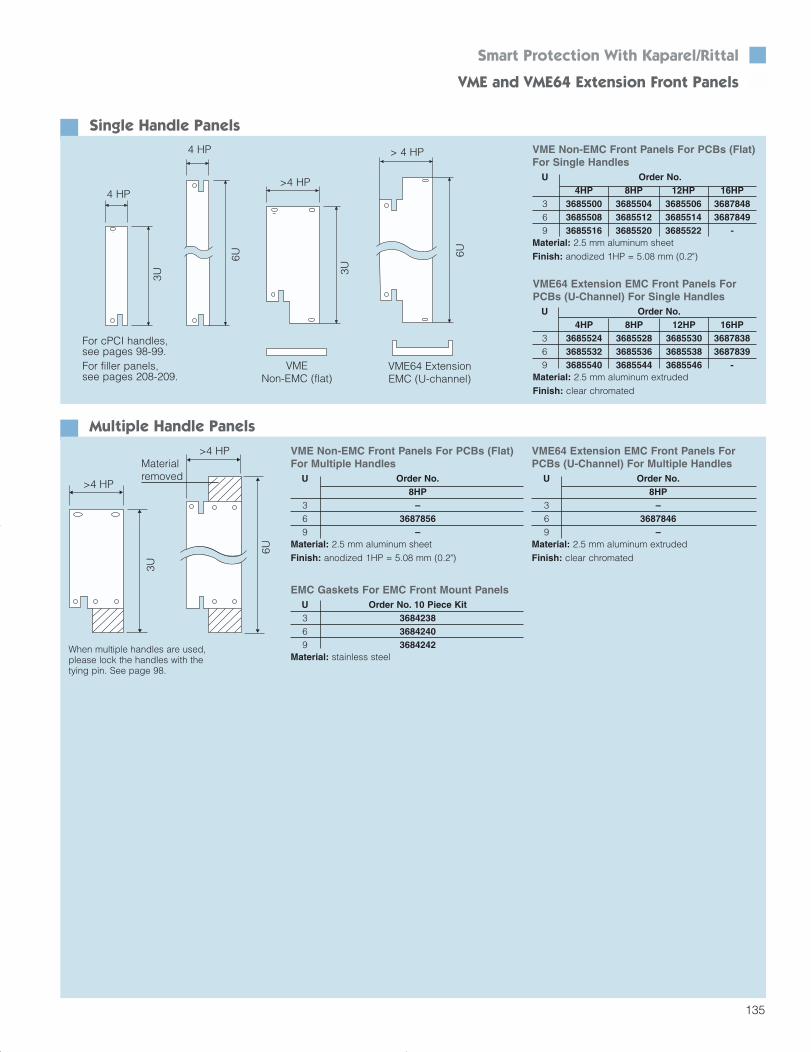
Smart Protection With Kaparel/Rittal VME and VME64 Extension Front Panels
Multiple Handle Panels
When multiple handles are used,please lock the handles with thetying pin. See page 98.
VME64 Extension EMC Front Panels ForPCBs (U-Channel) For Multiple Handles
U Order No.8HP
3 –6 36878469 –
Material: 2.5 mm aluminum extrudedFinish: clear chromated
VME Non-EMC Front Panels For PCBs (Flat)For Multiple Handles
U Order No.8HP
3 –6 36878569 –
Material: 2.5 mm aluminum sheetFinish: anodized 1HP = 5.08 mm (0.2")
3U
6U
>4 HP
>4 HP
Materialremoved
EMC Gaskets For EMC Front Mount PanelsU Order No. 10 Piece Kit3 36842386 36842409 3684242
Material: stainless steel
Single Handle PanelsVME Non-EMC Front Panels For PCBs (Flat)For Single Handles
U Order No.4HP 8HP 12HP 16HP
3 3685500 3685504 3685506 36878486 3685508 3685512 3685514 36878499 3685516 3685520 3685522 -
Material: 2.5 mm aluminum sheetFinish: anodized 1HP = 5.08 mm (0.2")
4 HP
4 HP
6U
3U 3U
6U
> 4 HP
>4 HP
VME64 ExtensionEMC (U-channel)
VME Non-EMC (flat)
For cPCI handles, see pages 98-99.For filler panels, see pages 208-209.
VME64 Extension EMC Front Panels ForPCBs (U-Channel) For Single Handles
U Order No.4HP 8HP 12HP 16HP
3 3685524 3685528 3685530 36878386 3685532 3685536 3685538 36878399 3685540 3685544 3685546 -
Material: 2.5 mm aluminum extrudedFinish: clear chromated
Section 3_104-155 4/7/04 8:47 AM Page 32
136
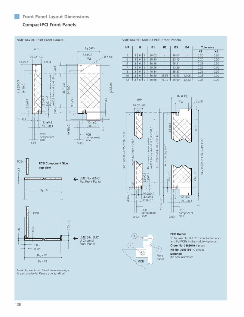
HP U B1 B2 B3 B4 ToleranceX1 X2
4 3 6 9 20.02 - 18.05 - 0.20 0.205 3 6 9 25.10 - 23.13 - 0.20 0.206 3 6 9 30.18 - 28.21 - 0.25 0.207 3 6 9 35.26 - 33.29 - 0.25 0.208 3 6 9 40.34 - 38.37 - 0.25 0.2010 3 6 9 50.50 35.56 48.53 43.06 0.25 0.2012 3 6 9 60.66 45.72 58.69 53.22 0.25 0.20
PCB HolderTo be used for 3U PCBs on the top endand 6U PCBs in the middle (optional).Order No. 3685619 1 pieceKit No. 3685198 10 piecesMaterial:die cast aluminum
2
3
1
PCB
Frontpanel
VME 64x 6U And 9U PCB Front PanelsVME 64x 3U PCB Front Panels
3.5±
0.1
6U =
255
.85±
0.1
/ 9U
= 3
89.2
±0.
1
2.5
2.5
PCB
1.0-0.1
2.54 6.
2 0.1
5
3.1
20.02 - 0.2
4.3
PCB Component Side
Top View
B3 + X1
B1 - X1
VME 64x EMC U-Channel Front Panel
VME Non-EMCFlat Front Panel
B1 - X2
7.5±0.1
94.5
±0.
13.
5±0.
1
8.2+
0.2
Max
imum
com
pon
ent s
pac
eon
PC
B fr
ont e
nd 3
U=
8130
94.5
±0.
13.
5±0.
1
2.6+
0.1
2.7 csk
B1 (HP)
B27.5±0.1
122.
5±0.
1
2.6
10.1±0.120.2±0.1
3.4±0.213.8±0.1
19.3
5±0.
1
3.92
PCB componentside
3.92
PCB componentside
10±0.1
B1 (HP)
B4
20.5
6U =
223
.35 -
/ 356
.7
6U =
262
.05-
0.3
/ 9U
= 3
95.4
-0.3
6U =
230
.35-
0.3
/ 9U
= 3
63.7
0-03
6U =
223
.35±
0.1/
356
.7
20.02 - 02
B1
3.5±
0.1 10.0±0.1
2.6+
0.1
8.2+
0.2
3.4±0.213.8±0.1
3.92
19.3
5±0.
1
PCB componentside
2.6+
0.1
3.5±
0.1
3.1
PCB componentside3.92
PCB
112.
85-0
.3
128.
7-0.
3
20.2±0.1
10.1±0.1
Max
imum
com
pon
ent s
pac
eon
PC
B fr
ont e
nd 6
U=
214.
5, 9
U=
347.
5
3.92
23.6
7.85
4HP
4HP
2.3 Ø
2.3 Ø
Note: An electronic file of these drawings is also available. Please contact Rittal.
Front Panel Layout Dimensions
CompactPCI Front Panels
Section 3_104-155 4/7/04 8:47 AM Page 33
102
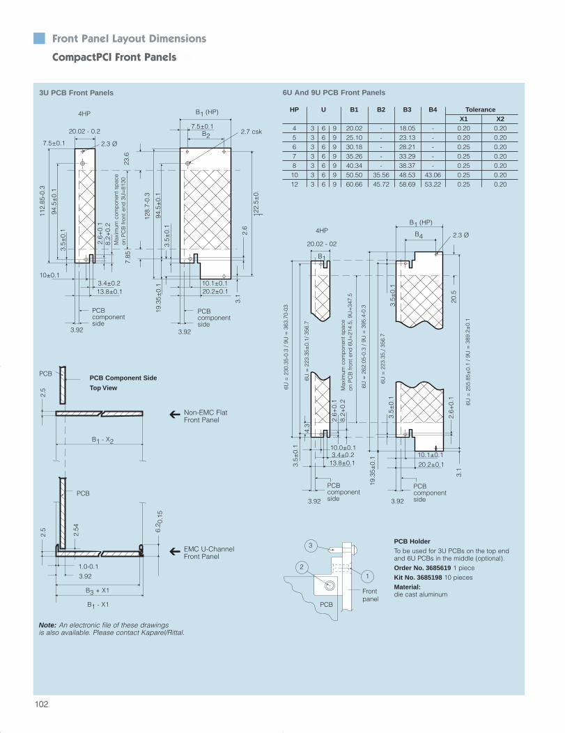
HP U B1 B2 B3 B4 ToleranceX1 X2
4 3 6 9 20.02 - 18.05 - 0.20 0.205 3 6 9 25.10 - 23.13 - 0.20 0.206 3 6 9 30.18 - 28.21 - 0.25 0.207 3 6 9 35.26 - 33.29 - 0.25 0.208 3 6 9 40.34 - 38.37 - 0.25 0.2010 3 6 9 50.50 35.56 48.53 43.06 0.25 0.2012 3 6 9 60.66 45.72 58.69 53.22 0.25 0.20
PCB HolderTo be used for 3U PCBs on the top endand 6U PCBs in the middle (optional).Order No. 3685619 1 pieceKit No. 3685198 10 piecesMaterial:die cast aluminum
2
3
1
PCB
Frontpanel
6U And 9U PCB Front Panels3U PCB Front Panels
3.5±
0.1
6U =
255
.85±
0.1
/ 9U
= 3
89.2
±0.
1
2.5
2.5
PCB
1.0-0.1
2.54 6.
2 0.1
5
3.1
20.02 - 0.2
4.3
PCB Component Side
Top View
B3 + X1
B1 - X1
EMC U-ChannelFront Panel
Non-EMC FlatFront Panel
B1 - X2
7.5±0.1
94.5
±0.
13.
5±0.
1
8.2+
0.2
Max
imum
com
pon
ent s
pac
eon
PC
B fr
ont e
nd 3
U=
8130
94.5
±0.
13.
5±0.
1
2.6+
0.1
2.7 csk
B1 (HP)
B27.5±0.1
122.
5±0.
1
2.6
10.1±0.120.2±0.1
3.4±0.213.8±0.1
19.3
5±0.
1
3.92
PCB componentside
3.92
PCB componentside
10±0.1
B1 (HP)
B4
20.5
6U =
223
.35 -
/ 356
.7
6U =
262
.05-
0.3
/ 9U
= 3
95.4
-0.3
6U =
230
.35-
0.3
/ 9U
= 3
63.7
0-03
6U =
223
.35±
0.1/
356
.7
20.02 - 02
B1
3.5±
0.1 10.0±0.1
2.6+
0.1
8.2+
0.2
3.4±0.213.8±0.1
3.92
19.3
5±0.
1
PCB componentside
2.6+
0.1
3.5±
0.1
3.1
PCB componentside3.92
PCB
112.
85-0
.3
128.
7-0.
3
20.2±0.1
10.1±0.1
Max
imum
com
pon
ent s
pac
eon
PC
B fr
ont e
nd 6
U=
214.
5, 9
U=
347.
5
3.92
23.6
7.85
4HP
4HP
2.3 Ø
2.3 Ø
Note: An electronic file of these drawings is also available. Please contact Kaparel/Rittal.
Front Panel Layout Dimensions
CompactPCI Front Panels n
Section 2_52-103 4/6/04 4:38 PM Page 51
202
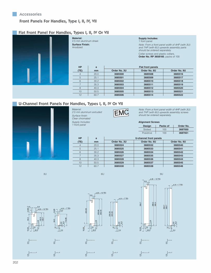
Accessories
Front Panels For Handles, Type I, II, IV, VII
Flat Front Panel For Handles, Types I, II, IV Or VIIMaterial:2.5 mm aluminum sheetSurface Finish:Anodized
HP a Flat front panels(TE) mm Order No. 3U Order No. 6U Order No. 9U
4 20.0 3685500 3685508 36855165 25.1 3685501 3685509 36855176 30.2 3685502 3685510 36855187 35.3 3685503 3685511 36855198 40.3 3685504 3685512 368552010 50.5 3685505 3685513 368552112 60.7 3685506 3685514 3685522
Supply Includes:1 front panelNote: From a front panel width of 4HP (with 3U)and 7HP (with 6U) upwards assembly partsshould be ordered separately.Collar screws and plastic collars, Order No. RP 3658160, packs of 100
U-Channel Front Panels For Handles, Types I, II, IV Or VIIMaterial:2.5 mm aluminum extrudedSurface finish:Clear chromatedSupply Includes:1 front panel
HP a U-channel front panels(TE) mm Order No. 3U Order No. 6U Order No. 9U
4 20.0 3685524 3685532 36855405 25.1 3685525 3685533 36855416 30.2 3685526 3685534 36855427 35.3 3685527 3685535 36855438 40.3 3685528 3685536 368554410 50.5 3685529 3685537 368554512 60.7 3685530 3685538 3685546
Note: From a front panel width of 4HP (with 3U)and 7HP (with 6U) upwards assembly screwsshould be ordered separately.
Alignment Screws
Design Packs of Order No.Slotted 100 3687050
Posidrive 100 3687051
7.47
14.8
5 a (4 — 7 TE)
112.
85
94.5
2.6
8.2
10
3.4
2.5
2.5
a (8 — 12 TE)
7.47
14.8
5
128.
7
3.3
5.9
122.
5
19.3
5 10
20.2
3.1
94.5
2.6
2.5
2.5
a (4 — 7 TE)
230.
35
223.
35
3.4
10
8.2
2.6
2.5
2.5
19.3
5
a (8 — 12 TE)
262.
05
5.9
3.3
255.
85
2.6
3.1
20.2
10
223.
352.
52.
5
a (4 — 7 TE)
3.4
10
8.2
2.6
356.
7
363.
7
2.5
2.5
389.
2
395.
4
a (8 — 12 TE)5.9
3.3
10
20.219.3
5
2.6
3.1
356.
72.
52.
5
3U 6U 9U
Section 5_200-257 4/7/04 8:58 AM Page 3
206
Accessories
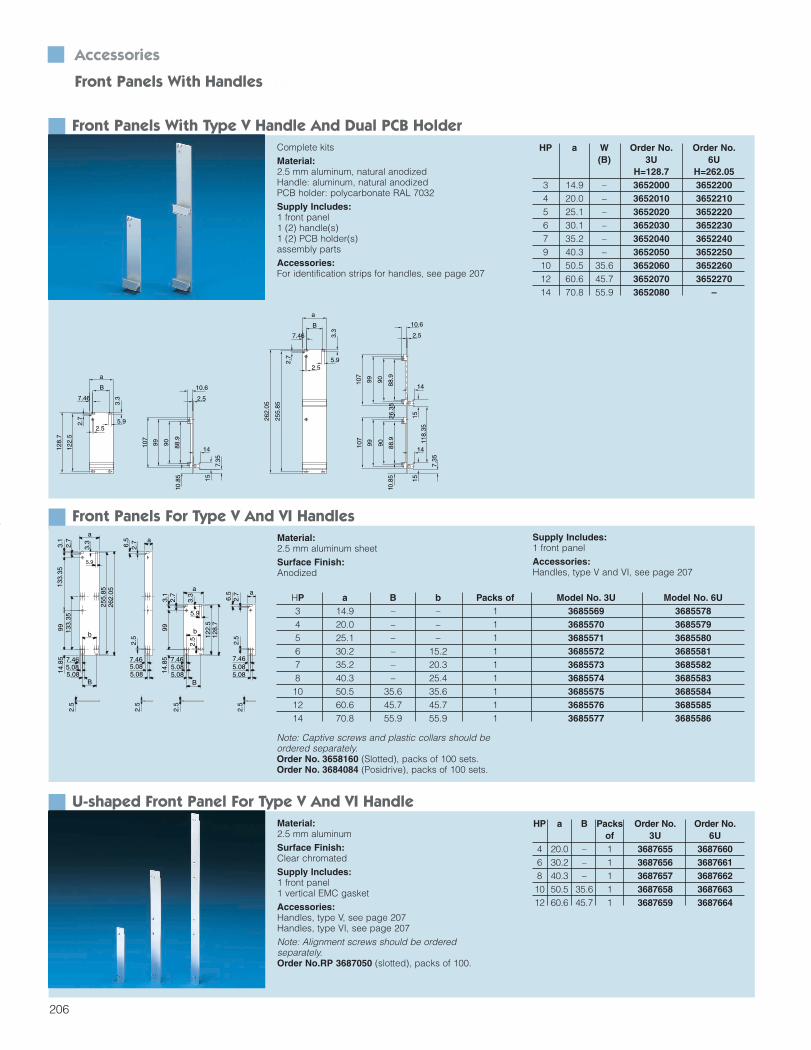
Front Panels With Handles n
Front Panels With Type V Handle And Dual PCB HolderComplete kitsMaterial:2.5 mm aluminum, natural anodizedHandle: aluminum, natural anodizedPCB holder: polycarbonate RAL 7032Supply Includes:1 front panel1 (2) handle(s)1 (2) PCB holder(s)assembly partsAccessories:For identification strips for handles, see page 207
a
7.465.085.08
6.5
2.7
2.5
a
5.085.087.46
6.5
2.5
2.7
7.465.085.08
B
5.9
3.3
a
14.8
599
133.
353.
12.
713
3.35
b
255.
8526
2.05
122.
5
99
a
B
128.
7
14.8
53.
1
5.9
3.3
2.5
2.7
5.085.087.46
2.5
2.5
2.5
2.5
b
Front Panels For Type V And VI HandlesMaterial:2.5 mm aluminum sheetSurface Finish:Anodized
HP a W Order No. Order No.(B) 3U 6U
H=128.7 H=262.053 14.9 – 3652000 36522004 20.0 – 3652010 36522105 25.1 – 3652020 36522206 30.1 – 3652030 36522307 35.2 – 3652040 36522409 40.3 – 3652050 365225010 50.5 35.6 3652060 365226012 60.6 45.7 3652070 365227014 70.8 55.9 3652080 –
107
9099
2.5
10.6
15
7.35
88.9
10.8
5
14
5.92.5
262.
05
3.3
255.
85
2.7
B
a
7.46
a
B
3.3
5.92.5
7.46
122.
5
128.
7
2.7
7.35
10.6
2.5
118.
35
9090
9999
88.9
10.8
526
.35
88.9
107
107
14
14
1515
Supply Includes:1 front panelAccessories:Handles, type V and VI, see page 207
HP a B b Packs of Model No. 3U Model No. 6U3 14.9 – – 1 3685569 36855784 20.0 – – 1 3685570 36855795 25.1 – – 1 3685571 36855806 30.2 – 15.2 1 3685572 36855817 35.2 – 20.3 1 3685573 36855828 40.3 – 25.4 1 3685574 368558310 50.5 35.6 35.6 1 3685575 368558412 60.6 45.7 45.7 1 3685576 368558514 70.8 55.9 55.9 1 3685577 3685586
Note: Captive screws and plastic collars should beordered separately. Order No. 3658160 (Slotted), packs of 100 sets.Order No. 3684084 (Posidrive), packs of 100 sets.
U-shaped Front Panel For Type V And VI HandleMaterial:2.5 mm aluminumSurface Finish:Clear chromatedSupply Includes:1 front panel1 vertical EMC gasketAccessories:Handles, type V, see page 207Handles, type VI, see page 207Note: Alignment screws should be ordered separately.Order No.RP 3687050 (slotted), packs of 100.
HP a B Packs Order No. Order No.of 3U 6U
4 20.0 – 1 3687655 36876606 30.2 – 1 3687656 36876618 40.3 – 1 3687657 368766210 50.5 35.6 1 3687658 368766312 60.6 45.7 1 3687659 3687664
Section 5_200-257 4/7/04 8:58 AM Page 7
207
Accessories Front Panels With Handles n
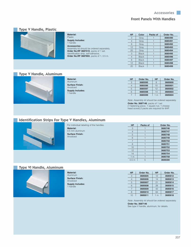
Type V Handle, PlasticMaterial:PlasticSupply Includes:1 handleAccessories:Assembly kit should be ordered separately,Order No.RP 3687519, packs of 1 set.Identification strip, self-adhesive,Order No.RP 3687693, packs of 1, 0.5 m.
HP Color Packs of Order No.3 Gray 1 36854904 Gray 1 36854918 Gray 1 368549212 Gray 1 368549320 Gray 1 36854943 Black 1 36854954 Black 1 36854968 Black 1 368549712 Black 1 368549820 Black 1 3685499
Type V Handle, AluminumMaterial:AluminumSurface Finish:AnodizedSupply Includes:1 handle
HP Order No. HP Order No.3 3685595 8 36856004 3685596 10 36856015 3685597 12 36856026 3685598 14 36856037 3685599 1 m 3685604
Note: Assembly kit should be ordered separately.Order No. 3687146, packs of 1 set(1 fastening piece, 1 square nut, 1 cheese head screw).2 packs are required for 6HP.
Identification Strips For Type V Handles, AluminumFor individual labeling of the handles.Material:0.5 mm aluminumSurface Finish:Anodized
HP Packs of Order No.3 1 36857464 1 36857475 1 36857486 1 36857497 1 36857508 1 368575110 1 368575212 1 368575314 1 3685754
1 m 1 36857580.5 m 5 3606300
Type VI Handle, AluminumMaterial:AluminumSurface Finish:AnodizedSupply Includes:1 handle
HP Order No. HP Order No.3 3685605 12 36856124 3685606 14 36856135 3685607 21 36856146 3685608 28 36856157 3685609 42 36856168 3685610 84 368561710 3685611 1 m 3685618
Note: Assembly kit should be ordered separately. Order No. 3687146See type V handle, aluminum, for details.
Section 5_200-257 4/7/04 8:58 AM Page 8

Front Panel AdaptersA typical application is when a 3U x 4 HP EMCplug-in unit is installed into a 6U system. Thisadapter kit provides for an additional 3U EMC fillerfront panel to be attached to the top end of theCPCI EMC front panel via a bracket.Note: The top handle is optional.
Packs of Order No.1 3687098
Board AdaptersA typical application is when two 3U CPU boardsare on top of each other, creating a 6U board system, where the enviroment requires two timesP1/J1-P2/J2 (typically two 3U 32-/64-bit CPCIboards in one slot). This kit provides for an adapterplate (FR4) to connect two CompactPCI boards tothe front panel and solder side cover (back cover)mounting holes. A modified 6U front panel isrequired; please inquire for additional information.
Packs of Order No.1 3687471
Ø2.70 CSK 4 places
146.70
153.67
160.52
51.3
5
44.4
5
35.0
0
Solder Side Covers
104
cPCI Solder Side Covers - SolidDescription For PCB size Qty Order No.
Solder side cover - solid 6U x 160 mm 1 3686574Solder side cover - solid 6U x 80 mm 1 3686573Solder side cover - solid 3U x 160 mm 1 3686572
Retention clip - 100 3687955
Accessories
n Solder Side Covers And Panel Adaptersn
A protective solder side cover mounted over thecomponent side 2 (backside) of the PCB may be required to prevent damage of backside components when cPCI front mounted modulesand/or cPCI rear mounted I/O modules areinstalled/extracted from the subrack (cPCI system).All cPCI modules having backside components orthrough-hole pins should provide a means formounting a protective cover (solder side cover).The positioning and the hole size for cPCI solderside cover mounting holes are defined in IEEE1101.11 Annex A and PICMG 2.0. While the solderside covers are optional per PICMG 2.0, the PICMG2.1 hot swap specification shall provide a means formounting a protective cover (solder side cover).Kaparel/Rittal offers two types of cPCI solder sidecovers – solid and vented. Solder side covers aremounted to the backside of the cPCI module PCB atthe front panel end with the existing PCB to frontpanel mounting screw and on the connector sidewith the plastic (removable) retention clip.
Configuration: Pentastat SC660/050C UL 94-VO Anti-static Surface resistivity of 1x10¹⁰ Ω/q Thickness .019"/0.5 mm Clear color Maximum temperature: +162°F/+72°C Non-washable Non-toxic, non-contaminating, reusable,
recyclable
Specifications: IEEE 1101.10 IEEE 1101.11 Annex A PICMG 2.0 PICMG 2.1 UL 94-VO (meets or exceeds
MIL-B-81705-C) Yellow board QMFZ 8; E17348A and E171348B
cPCI Solder Side Covers - Perforated With 2 mm HolesDescription For PCB size Qty Order No.
Solder side cover - perforated 6U x 160 mm 1 3687934Solder side cover - perforated 6U x 80 mm 1 3687933Solder side cover - perforated 3U x 160 mm 1 3687932
Retention clip - 100 3687955
Section 3_104-155 4/7/04 8:46 AM Page 1

208
Accessories
Front Panels – Handle, Type V, VI n
Dual PCB Holders For Front PanelsFor securing PCBs to front panels.Material:NorylSupply Includes:PCB holderAssembly parts
Packs of Order No.10 3606330
Filler Panels – Non EMCMaterial:Filler panel 2.5 mm aluminum sheet natural anodizedSupply Includes:1 front panelNote: Captive screws and plastic collars should be ordered separately. Order No. 3658160 (slotted), packs of 100.
b
B
a
7.46
5.9
3.3
H
H —
6.2
HP a Width b Order No. Order No. Order No. Order No. Order No. Order No. Order No. Order No. Order No.(B) 1U 2U 3U 4U 6U 7U 9U 10U 11U
H = 39.8 H = 84.25 H = 128.7 H = 173.15 H = 262.05 H = 306.5 H = 395.4 H = 439.85 H = 484.32 9.8 – – – – 3684889 – 3684911 – 3684738 – –3 14.9 – – – – 3684890 – 3684912 – – – –4 20.0 – – – – 3684891 – 3684913 – 3684739 – –5 25.1 – – – – 3684892 – 3684914 – – – –6 30.1 – – – – 3684893 – 3684915 – – – –7 35.2 – – – – 3684894 – 3684916 – – – –8 40.3 – – – – 3684895 – 3684917 – 3684740 – –10 50.5 35.6 – – – 3684896 – 3684918 – – – –12 60.6 45.7 – – – 3684897 – 3684919 – 3684741 – –14 70.8 55.9 – – – 3684898 – 3684920 – – – –20 101.3 86.4 – – – 3684899 – 3684921 – – – –21 106.4 91.4 – – 3685350 3684900 – 3684922 – – – –24 121.7 106.7 – – 3685429 – – – – – – –27 136.8 121.9 – – – 3684901 – 3684923 – – – –28 141.9 127.0 – – – 3684902 – 3684924 – – – –40 202.9 188.0 – – – 3684903 – 3684976 – 3684977 – –42 213.0 198.1 – 3684885 3684887 3684904 3684908 3684925 3684928 3684742 3684753 368475460 304.5 289.6 – – – 3684905 – – – – – –63 319.7 304.8 152.4 – – 3684906 3684909 3684926 3684929 – – –84 426.4 411.5 203.2 3684886 3684888 3684907 3684910 3684927 3684930 3684743 3684751 368475285 413.5 411.5 203.2 – – 3684744 3684745 3684746 3684747 3684748 3684749 3684750
Section 5_200-257 4/7/04 8:58 AM Page 9

209
Filler Panels, U-shaped For EMCMaterial:2.5 mm aluminum, extrudedSurface Finish:Clear chromatedSupply Includes:1 front panel, one-part or three-part 1 vertical EMC gasket1 contact strip (three-part only)1 gasket strip (three-part only)Note: Order alignment screws separately.Order No. RP 3687050 (slotted), packs of 100.
a
B7.47
2.3
H
H —
6.2
2.5
c
d
2.3
b7.47
2.5
H —
6.2
H
B
a
HP a Width b c d Order No. Order No. Order No. Order No. Order No. Order No. Order No. Order No. Order No.(B) 1U 2U 3U 4U 6U 7U 9U 10U 11U
H=39.8 H = 84.25 H = 128.7 H = 173.15 H = 262.05 H = 306.5 H = 395.4 H = 439.85 H = 484.32 9.8 – – – – – – 3685177 – 3685185 – 3685193 – –3 14.9 – – – – – – 3686138 – 3686139 – 3686140 – –4 20.0 – – – – – – 3685178 – 3685186 – 3685194 – –5 25.1 – – – – – – 3685179 – 3685187 – – – –6 30.1 – – – – – – 3685180 – 3685188 – – – –7 35.2 – – – – – – 3685181 – 3685189 – – – –8 40.3 25.4 – – – – – 3685182 – 3685190 – 3685195 – –10 50.5 35.6 – – – – – 3685183 – 3685191 – – – –12 60.6 45.7 – – – – – 3685184 – 3685192 – 3685196 – –14 70.8 55.9 – – – – – 3684249 – 3684258 – 3684278 – –16 80.9 66.0 – – – – – 3685373 – 3685453 – – – –20 101.3 86.4 – – – – – 3684250 – 3684259 – 3684279 – –21 106.4 91.4 – – – – – 3684272 – 3684275 – – – –27 136.89 121.9 61.0 – – – – – – – – – – –28 141.9 127.0 61.0 – – – – 3684251 – 3684260 – – – –40 202.9 188.0 91.5 – – – – 3684273 – 3684276 – 3684280 – –42 213.0 198.1 96.5 – – – – 3684252 3684255 3684261 3684264 3684267 – –60 304.5 289.6 96.5 193.0 – – – 3684274 – 3684277 – – – –63 319.7 304.8 101.6 203.2 – – – 3684253 3684256 3684262 3684265 3684268 – –84 426.4 411.5 101.6 203.2 304.8 3684247 3684248 3684254 3684257 3684263 3684266 3684269 3684270 3684271
Accessories Front Panels n
2 – 14 HP version one-part; > 14 HP version three-part
Section 5_200-257 4/7/04 8:58 AM Page 10
210
Accessories
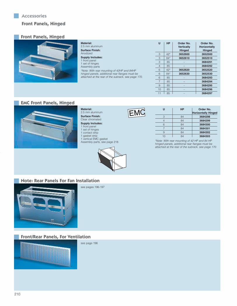
Front Panels, Hinged
Front Panels, HingedMaterial:2.5 mm aluminumSurface Finish:AnodizedSupply Includes:1 front panel1 set of hingesAssembly parts*Note: With rear mounting of 42HP and 84HP hinged panels, additional rear flanges must beattached at the rear of the subrack, see page 170.
U HP Order No. Order No.Vertically HorizontallyHinged Hinged
3 42* 3652600 36525003 84* 3652610 36525103 85 – 36842914 85 – 36842926 42* 3652620 36525206 84* 3652630 36525306 85 – 36842937 85 – 36842949 85 – 368429510 85 – 368429611 85 – 3684297
EMC Front Panels, HingedMaterial:2.5 mm aluminumSurface Finish:Clear chromatedSupply Includes:1 front panel1 set of hinges 1 contact strip1 gasket strip 1 vertical EMC gasketAssembly parts, see page 218
U HP Order No.Horizontally Hinged
3 84 36842984 84 36842996 84 36843007 84 36843019 84 368430210 84 3684303
Note: Rear Panels For Fan Installationsee pages 196-197
Front/Rear Panels, For Ventilationsee page 196
*Note: With rear mounting of 42 HP and 84 HP hinged panels, additional rear flanges must beattached at the rear of the subrack, see page 170.
Section 5_200-257 4/7/04 8:58 AM Page 11
196
Accessories
Ventilation – Front/Rear Panel
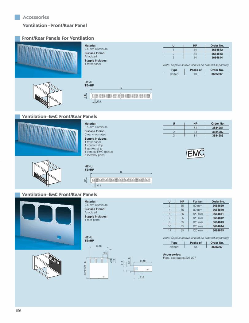
Front/Rear Panels For Ventilation
Ventilation–EMC Front/Rear Panels
U HP Order No.1 84 36848122 84 36848133 84 3684814
Note: Captive screws should be ordered separately.
Material:2.5 mm aluminumSurface Finish:AnodizedSupply Includes:1 front panel
Material:2.5 mm aluminumSurface Finish:Clear chromatedSupply Includes:1 front panel1 contact strip1 gasket strip1 vertical EMC gasketAssembly parts
Type Packs of Order No.slotted 100 3685097
HE
Ø 5
TE
U HP Order No.1 84 36842812 84 36842823 84 3684283
HE=UTE=HP
Ventilation–EMC Front/Rear PanelsMaterial:2.5 mm aluminumSurface Finish:AnodizedSupply Includes:1 rear panel
U HP For fan Order No.3 85 80 mm 36848394 85 80 mm 36848406 85 120 mm 36848417 85 120 mm 36848429 85 120 mm 368484310 85 120 mm 368484411 85 120 mm 3684845
Type Packs of Order No.slotted 100 3685097
Note: Captive screws should be ordered separately.
Accessories:Fans, see pages 226-227
HE=UTE=HP
HE
Ø 5
TE
85 TE
3/4
HE
85 TE
77
71.5
71.5
77
6/7/
9/10
/11
HE 10
5
116
105
16
HE=UTE=HP
Section 4_156-199 4/7/04 8:54 AM Page 41
197
Accessories Ventilation–Front/Rear Panel
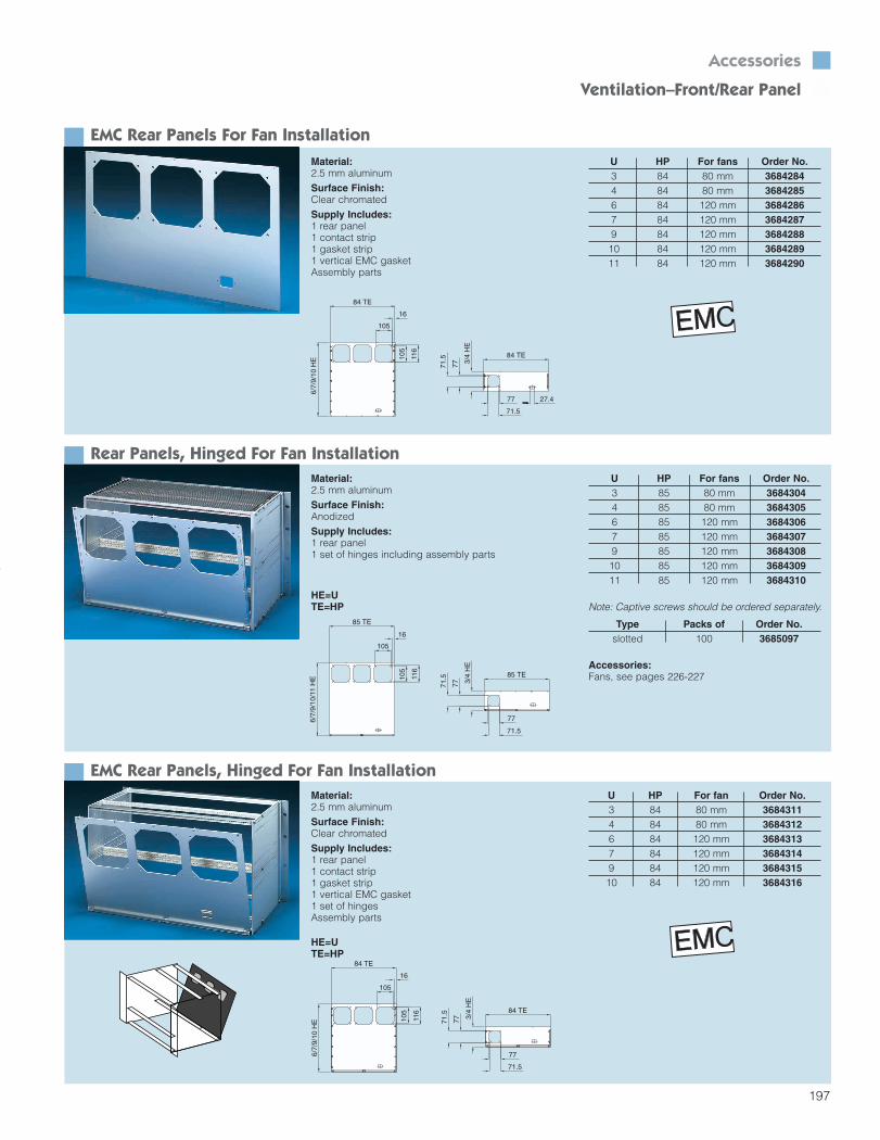
EMC Rear Panels For Fan Installation
Rear Panels, Hinged For Fan Installation
Note: Captive screws should be ordered separately.
Material:2.5 mm aluminumSurface Finish:Clear chromatedSupply Includes:1 rear panel1 contact strip1 gasket strip1 vertical EMC gasketAssembly parts
Material:2.5 mm aluminumSurface Finish:AnodizedSupply Includes:1 rear panel1 set of hinges including assembly parts
Type Packs of Order No.slotted 100 3685097
77
71.5
71.5
77
105
116
105
84 TE
3/4
HE
84 TE6/
7/9/
10 H
E
27.4
16
U HP For fans Order No.3 84 80 mm 36842844 84 80 mm 36842856 84 120 mm 36842867 84 120 mm 36842879 84 120 mm 368428810 84 120 mm 368428911 84 120 mm 3684290
85 TE
3/4
HE
85 TE
77
71.5
71.5
77
6/7/
9/10
/11
HE 10
5
116
105
16
HE=UTE=HP
EMC Rear Panels, Hinged For Fan InstallationMaterial:2.5 mm aluminumSurface Finish:Clear chromatedSupply Includes:1 rear panel1 contact strip1 gasket strip1 vertical EMC gasket1 set of hingesAssembly parts
U HP For fan Order No.3 84 80 mm 36843114 84 80 mm 36843126 84 120 mm 36843137 84 120 mm 36843149 84 120 mm 368431510 84 120 mm 3684316
77
71.5
71.5
77105
116
105
84 TE
3/4
HE
84 TE
6/7/
9/10
HE
16
HE=UTE=HP
Accessories:Fans, see pages 226-227
U HP For fans Order No.3 85 80 mm 36843044 85 80 mm 36843056 85 120 mm 36843067 85 120 mm 36843079 85 120 mm 368430810 85 120 mm 368430911 85 120 mm 3684310
Section 4_156-199 4/7/04 8:54 AM Page 42
Recommended