1
Abstract—Polar codes are a new class of error correcting
linear block codes, whose generator matrix is specified by the
knowledge of transmission channel parameters, code length and
code dimension. Moreover, regarding computational security, it
is assumed that an attacker with a restricted processing power
has unlimited access to the transmission media. Therefore, the
attacker can construct the generator matrix of polar codes,
especially in the case of Binary Erasure Channels, on which this
matrix can be easily constructed.
In this paper, we introduce a novel method to keep the
generator matrix of polar codes in secret in a way that the
attacker cannot access the required information to decode the
intended polar code. With the help of this method, a secret key
cryptosystem is proposed based on non-systematic polar codes. In
fact, the main objective of this study is to achieve an acceptable
level of security and reliability through taking advantage of the
special properties of polar codes. The analyses revealed that our
scheme resists the typical attacks on the secret key cryptosystems
based on linear block codes. In addition, by employing some
efficient methods, the key length of the proposed scheme is
decreased compared to that of the previous cryptosystems.
Moreover, this scheme enjoys other advantages including high
code rate, and proper error performance as well.
Index Terms— Code based cryptography, Polar codes, Secret
key cryptosystem.
I. INTRODUCTION
OWADAYS, development and rapid dissemination of
wireless communication systems have increased the
demand for providing reliable and secure data. In this respect,
channel coding is the study of techniques used for establishing
a reliable communication between a sender and a receiver in
the presence of channel errors. Cryptography is also known as
the study of various methods employed to build secure
communications in the presence of adversaries. In general,
channel coding can be applied to provide two major categories
of security; namely the information theoretic security and the
This work was supported in part by Iranian National Science Foundation
(INSF) Cryptography Chair.
Reza Hooshmand is with the Department of Electrical Engineering, Science and Research Branch, Islamic Azad University, Tehran, Iran (e-mail:
Mohammad Reza Aref is with the Department of Electrical Engineering, Sharif University of Technology, Tehran, Iran. (e-mail: [email protected]).
Taraneh Eghlidos is with the Electronics Research Institute, Sharif
University of Technology, Tehran, Iran. (e-mail: [email protected]).
computational security. Utilizing practical channel codes such
as Low Density Parity Check (LDPC) codes [1] and Polar
codes [2] in the structure of wiretap channel to achieve
secrecy capacity is an instance of applying channel codes in
establishing information theoretic security [3, 4]. In the same
vein, taking advantages of various channel codes in the
structure of public/secret key code based cryptosystems can be
regarded as an application of channel coding in providing
computational security [5, 6].
It is noteworthy that code based cryptosystems provide
security and reliability in one process to guarantee the
confidentiality and the integrity of the transmitted data.
Besides, a combination of security and reliability in the
structure of these systems can result in reducing the
processing cost or providing a rather higher efficiency.
Moreover, code based cryptosystems are considered as one of
the important classes of cryptographic systems which are
believed to resist quantum computers [7]. Establishing a
suitable tradeoff between security and reliability is thus one of
the important goals in designing such cryptosystems, which
can be properly achieved through efficient linear codes
employed in the structure of these cryptosystems.
The security of some code based cryptosystems is
dependent upon the difficulty of the general decoding problem
[8]. For an arbitrary binary linear code , with a length of
and dimension of , for instance, the general decoding
problem is that of decoding a channel output vector
( ) into the closest codeword
( ). In this case, the Hamming distance
between and , ( ) |{ | }|, is minimal
[9]. It was earlier proved that the decoding problem of
arbitrary linear codes belongs to the class of NP-complete
problems [8].
A. Related Works
In 1978, McEliece proposed the first public key
cryptosystem which was based on Goppa codes [5]. Compared
with other public key cryptosystems, McElieceʼs cryptosystem
enjoyed high speed encryption/decryption algorithms.
However, this scheme had its own weaknesses such as low
information rate and large key size. Later in 1984, the first
secret key code based cryptosystem was suggested by Rao
[10]. Although very similar to McElieceʼs cryptosystem, this
scheme kept the public key secret. It was shown later that
Raoʼs scheme could be broken by chosen plaintext attacks [6].
Secret Key Cryptosystem based on
Non-Systematic Polar Codes
Reza Hooshmand, Mohammad Reza Aref, and Taraneh Eghlidos
N

2
In 1986, Rao and Nam introduced a modified secret key
cryptosystem which allowed the use of short length Hamming
codes with high information rate while improving the security
level [6]. The modified scheme was called Rao-Nam (RN)
cryptosystem. Not unlike the McElieceʼs cryptosystem, the
security of RN scheme relies on the difficulty level at which
the general linear codes can be decoded. Many modifications to
RN scheme have already been proposed which are based on
either applying various channel codes in its structure or
modifying the set of allowed error vectors [11-15].
In the recent years, some efficient and secure secret key
cryptosystems based on Turbo codes [1] and LDPC codes have
been introduced. Turbo codes have also been employed in
different secure channel coding schemes to be used in satellite
communications [16, 17]. The issue of using quasi-cyclic low-
density parity-check (QC-LDPC) codes in secret key
cryptosystems is also addressed in [18, 19]. Due to the cyclic
and sparse structure of the parity check matrix of QC-LDPC
codes, the key lengths of these schemes were decreased
significantly compared with previous RN-like schemes.
The idea of applying polar codes to provide information
theoretic security has extensively been addressed in several
researches [4, 20]. However, in spite of the interesting
properties of the polar codes, these efficient codes have not
been applied in the structure of cryptosystems based on
general decoding problem. Recently, we introduced, for the
first time to the best of our knowledge, the application of polar
codes in the structure of secret key cryptosystem over binary
erasure channel [21]. In fact, the present paper is a
continuation and extension of our previous work in the context
of secret key cryptosystems based on channel coding.
B. Contributions of the proposed scheme
The present paper is aimed at introducing a secret key
cryptosystem which makes use of non-systematic finite length
polar codes in an efficient way to overcome the problems
arisen from insecure and unreliable communication channels.
The proposed scheme is designed in such a way so as to avoid
the weaknesses of the RN cryptosystem and is expected to
provide more security and reliability. The main contribution of
this work is the technique proposed for hiding the generator
matrix of polar codes from the attacker. In fact, with the help of
this method, the underlying cryptosystem can achieve a proper
security level based on general decoding problem.
It has to be noted that the proposed scheme resists against
the typical attacks on the cryptosystems based on channel
coding. In addition, its error performance, key length and
computational complexity will also be investigated to assess
the efficiency. In order to evaluate the reliability of this
scheme, the upper bound on error probability of the polar code
used under Successive Cancelation (SC) decoding is being
discussed in details as well. To decrease the key size of this
scheme, we apply efficient techniques including, (1) utilizing
the special structure of the generator matrix of polar codes, (2)
using the efficient method based on pseudorandom number
generator [22] to generate the nonsingular and permutation
matrices, and (3) exploiting the non-systematic property of
polar codes to generate the intentional error vectors. In fact, it
is shown that the proper tradeoff between the security and
reliability is attainable through the proposed scheme.
C. Outline
The rest of this paper is organized as the follows. Sections
II & III give brief reviews of the polar codes and Rao-Nam
cryptosystem, respectively. The concept of using polar codes
in the structure of secret key cryptosystem is introduced in
Section IV. The efficiency and security levels of the proposed
cryptosystem are also assessed in Sections V & VI
respectively. Finally, Section VII concludes the paper with a
brief discussion of the future work.
II. POLAR CODES
In this section, a brief description of the structure of polar
codes will be presented and subsequently, an existing
technique for constructing their generator matrix will be
reviewed. Polar codes are a class of linear block codes that
provably achieve the capacity of any symmetric Binary-input
Discrete Memoryless Channel (B-DMC), such as BEC and
Binary Symmetric Channel (BSC). Let be a B-
DMC with input alphabet of { }, output alphabet of
and transition probabilities of { ( | ) }. Let us
consider the following parameters for a B-DMC [2].
( ) ∑ ∑
( | )
( | )
( | )
( | )
( ) ∑ √ ( | ) ( | )
where ( ) [ ] is the mutual information between the
input and the output of with uniform distribution on the
input. When is a symmetric channel, ( ) is called the
capacity of and thus applied as the measure of rate. Besides,
( ) [ ] is known as the Bhattacharyya parameter of
and used as a criterion of measuring reliability. Note that
( ) iff ( ) , also ( ) iff ( ) . If is a
BEC with erasure probability , denoted by BEC( ), then
( ) and ( ) ( ) [2].
Let { ( )
} be a set of polarized binary input
channels with indices ʻ ʼ that can be obtained by performing a
phenomenon on the independent copies of given B-DMC
. This phenomenon is called channel polarization and the
polarized binary input channels are called bit-channels or sub-
channels. By exploiting the channel polarization, the
symmetric capacity terms { ( ( )
) } and
Bhattacharya parameters { ( ( )
) } of all bit-
channels tend to 0 or 1 if is large enough [2]. In the
remainder of this paper, the Bhattacharya parameter of -th bit-
channel, ( ( )
), is denoted by . Besides, we consider the
methods which are proposed to obtain the Bhattacharya
3
parameters of the bit-channels. Such parameters are necessary
to construct the generator matrix of polar codes.
Let { } be a set of all bit-channel indices. Let
be a -element subset of which is called information set.
Let be an ( )-element subset of which is a
complement to the subset and is called frozen (fixed) set.
These sets are specified in such a way that for all
. In other words, it is possible to construct bit-
channels such that their ( ) with indices in the information
set tend to become reliable or noiseless and their ( ( ))
with indices in the frozen set tend to become unreliable or
noisy [2, 23].
A. Constructing the Generator Matrix
Consider and [
]. Given the rate
( ) and the dimension , a generator
matrix is constructed for any ( ) polar code through the
following steps [24]:
1) Compute the -th kronecker product which
gives an matrix. Then, label the rows of from
top to bottom as .
2) Obtain the Bhattacharyya parameters of all bit-
channels in the form of ( ) through
the following recursive formula with initial condition
.
{
(1)
If the channel is a BEC( ), the initial condition is
equal to .
3) Form a permutation ( ) for the set of bit-
channel indices { } in such a way that the
inequality is satisfied.
4) Obtain the information set whose bit-channel
indices correspond to leftmost indices of the
permutation , i.e. . Then, obtain the frozen set
whose bit-channel indices correspond to
rightmost indices of the permutation , i.e.
.
5) Construct the generator matrix by choosing rows of
the matrix which correspond to the bit-channel
indices of the information set . If the bit-channel ( )
is
chosen, then the -th row of is selected. Also,
construct ( ) matrix by selecting rows
of corresponding to the bit-channel indices of the
frozen set .
In short, the Bhattacharya parameters { } of all
bit-channels { ( )
} are generated by recursive
formula (1). Then, the generator matrix is constructed by
choosing the rows of the matrix whose indices
correspond to bit-channels with the least possible
Bhattacharya parameters.
B. Non-Systematic Encoding
Polar codes, introduced in [2], are in fact non-systematic
codes. In systematic encoding, the information bits appear
transparently as part of the codeword, while this is not the case
in the non-systematic encoding. In the case of non-systematic
polar codes with block length of , an input vector
( ) ( ) consists of two subvectors, namely
the information vector, which is a -bit subvector (
) and the frozen (fixed) vector which is an ( )-bit
subvector ( ). The information vector
comprises of information data that is free to change in each
process of transmission, while the frozen vector consists of
fixed values known to decoder [25]. In addition, the input
vector is encoded to -bit codeword as follows,
.
Since is a fixed vector, the encoder mapping to
is non-systematic [25]. The code rate is defined as | | | |⁄ | | ⁄ which can be adjusted by selecting the size of
information set . The coordinates of the information vector
can be transmitted at a rate close to 1 through noiseless bit-
channels. However, the coordinates of the frozen (fixed)
vector can be transmitted at a rate close to 0 across the noisy
bit-channels. Therefore, polar codes are efficient for channel
coding [2].
C. Successive Cancellation Decoding
Let be an -bit codeword of the polar codes which is
transmitted across the bit-channels. Let be the
corresponding channel output vector which is decoded by the
low complexity SC decoding algorithm. The main goal of the
SC decoder is to obtain the estimated input vector by the
knowledge of information set frozen vector and as well
as the channel output vector . The bits of input vector are
estimated successively at the SC decoder in the following way
[2],
{
(
)
where decision functions , are
computed as below for all
,
(
) {
( )
(
| )
( )
(
| )
.
The information bits , are estimated one by one
using the -th decision element after the channel output vector
and the previous estimated information bits are known.
Furthermore, the value of frozen bits, , is known to
the SC decoder. It has been proved that for any given B-DMC
, the error probability under SC decoding is upper bounded
as follows [2],
∑ . (2)

4
Also, it has been indicated that reliable communication
using SC decoder is obtained when the following relation is
satisfied [26, 27],
( ) ⁄ , (3)
where is the scaling exponent, whose values depends on the
choice of channel. Its value for BEC, for instance, is
approximately equal to 3.627. Indeed, reliable communication
under SC decoding for any B-DMC is obtained when the
rate is less than the capacity at least to the extent of ⁄ . It
can be considered as a tradeoff between the rate and the block
length of polar codes for a given error probability, when the
SC decoder is utilized [27]. In this paper, the maximum
possible code rate fulfilling (3) is named by cutoff rate and
denoted by .
III. THE RAO-NAM CRYPTOSYSTEM
The Rao-Nam (RN) cryptosystem is an important secret key
code based cryptosystem used as a reference to measure the
security and efficiency of secret key cryptosystems based on
error correcting codes. In this section, the structure of RN
scheme is being described, followed by an in-depth
investigation of its drawbacks.
A. Secret Key
The secret key of the RN scheme consists of the parameters
{ } which are explicated as follows [6]:
1) Let be a generator matrix of the binary linear
code .
2) Let be a random binary nonsingular matrix
(scrambler).
3) Let be an random binary permutation matrix
(permutor).
In RN cryptosystem, a set of predetermined -bit
intentional error vectors, { }, with cardinality
is considered which has two main properties. The
first property, called the weight property, is that all error
vectors have the average Hamming weight equal to half of the
code length, ( ) ⁄ . The second property, i.e. the
syndrome property, is that no distinct error vector is located in
the same coset of [28]. According to these definitions, the
syndrome error table can be defined as follows.
4) Let { | } be a predetermined set of error
vectors which is also called the syndrome error table.
This set consists of cosets each of which has a
distinct syndrome . Therefore, any set of -bit
error vectors can be selected, one from each of
cosets.
B. Encryption
A -bit message ( ) is encrypted into an
-bit ciphertext ( ) as shown below [6].
( ) ,
where is a encryption matrix. Besides, denotes an
-bit intentional error vector selected randomly from the
syndrome error table .
C. Decryption
A ciphertext is decrypted into a plaintext using secret
keys , and following the steps below [6].
1) Compute , .
2) Calculate the syndrome
, . Find the corresponding error vector
from the syndrome error table .
3) Obtain and recover using the decoding
algorithm.
4) Multiply by to retrieve the message .
D. Weaknesses
The RN scheme has several drawbacks as being discussed
below:
1) One of disadvantages of the RN scheme is that it needs
to store the matrices and . Similarly, the syndrome
error table should be saved to remove the errors in the
decryption process. Therefore, a large amount of secret
keys are exchanged and stored by both the sender and
the receiver [6].
2) Yet another practical problem of this scheme lies in the
small number of error vectors for their recommended
code parameters, e.g. for ( )
Hamming code. Hence, the RN scheme is vulnerable to
chosen plaintext attacks [6]. Another drawback is the
possibility of estimating the rows of encryption matrix
of this scheme using the majority voting analysis [28,
29].
3) In RN scheme, there exists a tradeoff between the code
rate and the security. In fact, the code length is
impractical for having a high code rate and a large
number of intentional error vectors [11]. Furthermore,
the RN scheme preserves the error correction capability
of the employed code only partially [30].
Given the mentioned shortcomings, this research attempts
to address these problems through applying the interesting
properties of non-systematic polar codes and other efficient
methods.
IV. THE PROPOSED CRYPTOSYSTEM
The proposed secret key cryptosystem is designed based on
finite length polar codes so that channel errors are corrected
and the information is concealed from an unauthorized user.
To this end, we consider the transmission over a BEC( ), as it
has been shown that among all the B-DMCs , the best
tradeoff between rate and reliability belongs to BEC. In other
words, for a BEC, the Bhattacharyya parameter ( ) is
minimized among all channels with a given capacity ( )
( ). Besides, given the general B-DMCs, no efficient
algorithm has been introduced so far to calculate the
Bhattacharya parameters. For a BEC, however, these
parameters are constructed efficiently using (1) [2].

5
Therefore, unlike the other B-DMCs, the method used for
constructing polar codes is simple for the BECs and can thus
be performed with a complexity of ( ) [24].
A. A technique for hiding the generator matrix of polar codes
In the computational security, it is assumed that the attacker
has unlimited access to the transmission channel. Moreover,
the generator matrix of the polar codes has a channel dependent
structure. This can imply that the attacker can specify the
generator matrix of these codes using the channel parameters,
length and dimension of the intended polar code. The main
question being addressed in the currecnt study is that of how
to keep the generator matrix of polar codes secret from the
attacker to use these efficient codes in the structure of
cryptosystems based on general decoding problem. In response
to this issue, an efficient method is being proposed here,
through which, an attacker cannot construct the hidden
generator matrix of polar codes over BEC( ) even if the
parameters and are known. Letʼs consider the set of
bit-channel indices { }, the permutation
( ) and the cutoff rate for an ( ) polar
code, as defined in Section II.
Remark 1. The bit-channels are regarded as Good bit-
channels if the corresponding Battacharya parameters are
minimized (i.e. the least error probability) among all bit-
channels. That is, the indices of good bit-channels in the set
correspond to the indices { } .
Remark 2. The ( ) bit-channels are regarded as Bad
bit-channels if the corresponding Battacharrya parameters are
maximized (i.e. the most error probability) among all bit-
channels. That is, the indices of bad bit-channels in the set
correspond to the indices { } .
The following section explains how the generator matrix of
polar codes can be kept secret.
1) Consider the method of constructing the generator matrix
for an ( ) polar code as discussed in Section II-A.
First, all Bhattacharya parameters of bit-channels,
, and the permutation are constructed.
Now, in order to keep the generator matrix secret,
indices are selected randomly from the indices of good
bit-channels. Indeed, this step is equivalent to the random
selection of bit-channels from good bit-channels.
Subsequently, the randomly selected indices of the set
are considered as the secret information set, denoted by
( ). In fact, ( ) is the subset of with randomly
selected indices of good bit-channels.
The secret generator matrix ( ) is defined as a
submatrix of whose rows are chosen in accordance
with the indices of ( ). If the cutoff rate , the length
, and the dimension , are selected properly, the
number of polar codes equivalent to the used code is
large enough. In this case, an attacker cannot obtain the
secret generator matrix in polynomial time. However, as
it is discussed in Section V-A, most probably, this
selection is not the best choice to achieve channel
capacity. Indeed, there is a tradeoff between the security
and efficiency which is usually inevitable in
cryptosystems based on channel coding.
2) The secret frozen (fixed) set, denoted by ( ), is a subset
of whose elements are the non-selected indices
of the set in step 1. Moreover, the secret matrix ( ) is
defined as an ( ) submatrix of whose
rows are chosen based on the indices of the secret frozen
set.
3) In order to have a more secure decoding process, the
frozen vector should be concealed from an adversary.
Since the polar code performance is not sensitive to the
manner in which the frozen vector is selected, it makes
no big difference how this vector is chosen [2].
Therefore, in the encryption/decryption process of the
proposed scheme, an ( )-bit randomly chosen vector
is generated by an ( )-bit LFSR to be used as the
secret frozen vector, denoted by ( ). As a result, the
number of possible frozen vectors is equal to
. As long as the length and dimension of the
employed polar code are selected properly, the attacker
cannot find the secret frozen vector in polynomial time.
The inputs to SC decoder of polar codes are the channel output
vector, the information set and the frozen vector. Hence, by
hiding the information set and the frozen vector using the
above technique, the attacker cannot decode the channel
output vector to the estimated input vector in polynomial
time. Fig. 1(a, b) represents the proposed concept for
providing security based on polar codes.
Good
bit-channels
Bad
bit-channels
Selecting
randomly
good
bit-channels
remained
bit-channels
(a)
remained
bit-channels
Secret
frozen
vector
randomly
selected good
bit-channels
randomly
selected good
bit-channels
Secret
information
vector
(b)
Fig. 1. The proposed concept for providing security based on polar codes,
(a). The bit-channels are selected randomly from good bit-channels,
(b). The secret information vector is transmitted through randomly selected
good bit-channels. Also, the secret frozen vector is transmitted across
remained bit-channels

6
It is observable from Fig. 1(a) that, in order to hide the
generator matrix ( ), the bit-channels are selected
randomly from good bit-channels. In Fig. 1(b), the secret
information vector, denoted by ( ), is transmitted through
the randomly selected good bit-channels. Besides, it can be
viewed that the secret frozen vector is transmitted across
the remained bit-channels. In this case, should the
parameters , and are selected properly, an attacker
cannot recognize on which bit-channels the secret information
vector is transmitted. Thus the secret generator matrix ( )
cannot be constructed by the attacker even if the transmission
channel parameters, the length and dimension of the utilized
polar code are known.
B. Secret Key
The set of keys which should be kept secret is
{ ( ) }. In this set, ( ) is a generator matrix of
polar codes requiring bits of memory, is a set of -bit
intentional error vectors requiring | | bits of memory, is a
random binary nonsingular matrix and is an
random binary permutation matrix which require and
bits of memory, respectively. By saving the set , the key
length of the proposed scheme enlarges. Therefore, efficient
methods are applied to reduce the size of the exchanged key
dramatically. In this case, the secret key set is
{ ( ) } which consists of the parameters as
follows:
1) As mentioned before, the secret generator matrix of an
( ) polar code is defined as the submatrix of
whose rows are chosen based on the indices of the secret
information set ( ). Hence, it will suffice to store only
( ) instead of ( ). On the other hand, since the secret
frozen set is complement to secret information set and
requires less memory to save, so it is possible to store
( ) instead of ( ).
2) Let be a ( )-bit initial vector to generate a binary
pseudorandom sequence by a ( )-bit LFSR. The generated pseudorandom sequence is used
to construct the binary nonsingular matrix (see
Section V-B for more details).
3) Let be an ( )-bit initial vector of LFSR to generate
a binary pseudorandom sequence by an
( )-bit LFSR. The generated pseudorandom sequence
can be used to construct the binary permutation matrix
(see Section V-B for more details).
4) Let be an ( )-bit initial vector to generate an
( )-bit vector by an ( )-bit LFSR. Due to the
non-systematic property of the employed polar code, the
generated vector is used as secret frozen vector ( ).
Thus, ( ) ( ) can be considered as an -bit
intentional error vector and { } with
cardinality as a set of -bit intentional error
vectors. Apparently, unlike the RN cryptosystem, there is
no need to store the syndrome error table .
It will be illustrated later in Section VI that reducing the key
size of the proposed scheme by these efficient methods does
not decrease the security level of the system.
C. Encryption
1) The sender first randomly chooses a code in a family of
equivalent ( ) polar codes by selecting indices at
random from indices of good bit-channels. Then, the
sender generates an ( )-bit frozen vector randomly
using an LFSR with the initial value . In order to
perform the decryption process properly, it is necessary
to synchronize the sender and the receiver. This way, the
frozen vector employed by the sender is known to the
receiver synchronously. Subsequently, an intentional
error vector is constructed.
2) Finally, each -bit message is encrypted into an -bit
ciphertext as shown below.
( ( ) ( ) ( ))
( ) ( ) ( )
, (4)
where ( ) is a encryption matrix
equivalent to the generator matrix ( ).
D. Decryption
The ciphertext is transmitted over the insecure channel
and the channel output vector is
decrypted by the authorized receiver as described below.
1) The transposed permutation matrix, , is multiplied by
the channel output vector and
( ) is computed to remove the
permutation matrix . In this case, is a vector
having the same Hamming weight as .
2) The authorized receiver makes use of the secret initial
value to generate the secret frozen vector. Then, the
set { ( ) ( ) } is considered as the input to the SC
decoder. Finally, the input vector ( ( ) ( ))
( ( )) is estimated by the SC decoder as:
{ ( )
(
) ( ),
where the decision function , ( ),
is defined as:
(
) {
( )
(
| )
( )
(
| )
, ( ).
3) Having obtained the secret information vector ( )
using the SC decoder, we can now recover the
message as ( ) .
The secret information set ( ) and secret frozen vector ( )
are necessary to initiate the SC decoder. Therefore, it is
computationally infeasible for any unauthorized user to
correct channel errors without the knowledge of parameters
( ( ) ( )). Fig. 2 illustrates the block diagram of the
proposed cryptosystem. As can be viewed from this figure, at
the first step, the message is multiplied by the nonsingular

7
matrix . Then the -bit secret information vector ( )
is encoded to the -bit codeword ( ) ( ) ( ) ( ).
Eventually, the -bit ciphertext is obtained through
multiplying the codeword by the permutation matrix .
SourcePolar code
Encoder
Insecure
Channel
DestinationSC
Decoder
Decipher
Encipher
Fig. 2. Block diagram of the proposed cryptosystem.
The received vector is also arrived at by transmitting the
ciphertext through an insecure channel, which is then
multiplied by the transposed permutation matrix. In the next
step, the vector ( ) is obtained by performing the SC
decoding on the -bit vector . Finally, the message
is recovered by multiplying the vector ( ) by the inverse of
the nonsingular matrix .
V. EFFICIENCY
The efficiency of the proposed cryptosystem is evaluated in
terms of its error performance, key length and computational
complexity. A detailed account of the observations is being
provided below.
A. Error Performance
The error performance of the used finite length polar codes
is being analyzed under SC decoding. Yet the following
remarks are to be taken into consideration first:
Remark 3. Let be a subset of { } whose
elements correspond to the indices { } . The
minimum upper bound on error probability under SC
decoding is equal to the sum of Battacharya parameters of
bit-channels whose indices are the elements of the subset ,
i.e. ∑ .
It has to be noted that this upper bound is the same as the
standard upper bound on error probability of polar codes under
SC decoding [2].
Remark 4. Let be a subset of { } whose
elements correspond to the indices
{ } . The maximum upper bound
on error probability under SC decoding is equal to the sum of
the Battacharya parameters of bit-channels whose indices
are the elements of the subset , i.e. ∑ .
In the proposed scheme, since bit-channels are selected
randomly from good bit-channels, the upper bound on the
error probability can vary from to depending on the sum
of the Battacharya parameters of selected good bit-channels.
In the sequel of this section, it will be discussed how some
parameters such as erasure probability , code length , code
rate , and the manner in which the secret information set ( )
is selected can affect and .
If the transmission channel is BEC( ), the initial value of
the recursive formula (1) will be . Therefore, the
erasure probability should be considered such that reliable
communication is achieved. In this work, we consider the
condition to have a reliable communication where
has different values, depending on the application of the
proposed scheme. Here, we select and based on which
the analysis of the error performance is subsequently carried
out. The erasure probabilities of BEC should be considered in
a way that is less than or equal to . In this case, is
definitely less than . As shown in table I, erasure
probability varies in different intervals depending on the code
lengths to satisfy the condition .
TABLE I
DIFFERENT INTERVALS ON ERASURE PROBABILITY TO SATISFY
[ ] [ ] [ ]
[ ] [ ]
It is obvious that for larger code lengths, we can provide
larger intervals on to achieve reliable communication. In
addition, the code rate should be chosen in a way that .
In this scheme, in order to obtain a secure and reliable
communication, finite length polar codes with high rate are
employed. For instance, we consider a ( ) polar code
with over BEC(0.01). Note that for BECs with
larger or smaller , it is possible to select other code rates
depending on the application. For example, we will have
if for the fixed block length .
Fig. 3 presents the variations of and in terms of
[ ]. The polar code of length is considered
over BECs with . Two sets of three curves are
depicted in this figure. The solid and the dashed lines plot
and vs. code rate, respectively. As is evident in this figure,
depends on the variations of the rate and erasure
probability. Furthermore, the cutoff rate is increased as the
erasure probability is decreased. It is also viewed that the
cutoff rate is equal to and for the erasure
probabilities of and , respectively. This signifies
the possibility to achieve reliable communication at higher
code rates by increasing the cutoff rate .

8
0.55 0.6 0.65 0.7 0.75 0.8 0.85 0.910
-35
10-30
10-25
10-20
10-15
10-10
10-5
100
Code rate
Upper
bounds o
n b
lock e
rror
pro
babili
ty
R0=0.8
R0=0.84
R0=0.75
Pe1(erasure prob.=0.01)
Pe2(erasure prob.=0.01)
Pe1(erasure prob.=0.05)
Pe2(erasure prob.=0.05)
Pe1(erasure prob.=0.1)
Pe2(erasure prob.=0.1)
0.5 0.55 0.6 0.65 0.7 0.75 0.8 0.85 0.910
-30
10-25
10-20
10-15
10-10
10-5
100
R0=0.8
R0=0.89
Code rate
Upper
bounds o
n b
lock e
rror
pro
babili
ty
Pe2 (N=210)
Pe1 (N=210)
Pe1 (N=215)
Pe2 (N=215)
Fig. 3. Variations of and vs. rates [ ] for the polar code of
length over BECs with .
On the other hand, is rate-independent. The main reason
behind this is that the Battacharya parameters corresponding
to set are rather small (approximately close to zero)
compared to the ones corresponding to set . Therefore,
unlike the upper bound , the value of is invariable in
terms of rates. For the ( ) polar code over BEC(0.01),
the upper bound on the error probability can vary from
∑ to ∑
. According to remarks 3 and 4, and are
the subsets of { } whose elements correspond
to the indices { } and { } , respectively.
The code length is another parameter affecting and
in the proposed scheme. Fig. 4 depicts the variations of
and in terms of the rates [ ] for the polar codes of
lengths over BEC( ). It is observable that both
and are decreased as the code length is increased.
Further, the cutoff rate increases as the code length is
enlarged. As can be seen, for the lengths , the
cutoff rate is equal to 0.8 and 0.89, respectively. In other
words, it is possible to achieve reliable communication at
higher code rates through increasing the code length.
Fig. 4. Variations of and vs. rates [ ] for the polar codes of
lengths over BEC( ).
Moreover, as mentioned before, the intentional error vectors
( ) ( ) do not affect the error correction capability of
the polar codes as the polar code performance is not sensitive
to the way the frozen vector ( ) is selected. Therefore, the
error correction capability of the polar codes is fully preserved
in this scheme.
B. Key Length
In this scheme, the memory requirement of the secret key set
{ ( ) } is computed as below:
As mentioned before, the secret frozen set ( ) can be 1)
saved instead of the generator matrix ( ). On the other
hand, the largest possible bit-channel index, i.e. , might be one of the indices in ( ). Such bit-
channel index requires 11 bits to save in binary form.
Hence, the upper bound on the required memory to store
( ) is computed as ( ) ( ) bits.
The required memory to store the initial value is 2)
computed as bits.
In this scheme, a ( ) polar code is considered to
obtain reasonable reliability and security simultaneously. On
the other hand, if the nonsingular matrix and the
permutation matrix are saved directly, the key
length grows too large. Consequently, we attempt to apply the
efficient method introduced in [22] to reduce the key length.
This method is based on pseudorandom number generators,
i.e. LFSRs, to reduce the memory requirements of these
matrices. In this case, the short initial values and are
saved instead of the matrices and , respectively. This
method takes advantage of a special type of matrices, called
double-one (DBO) matrices [31], in which every single row or
column contains exactly two 1s. The DBO matrix is called a
DBO-1 matrix if all 1s in the matrix can be connected in a
unique cycle alternately in the column and row directions. It
has to be noted that all DBO-1 matrices are singular, and the
rank of any DBO-1 matrix is according to [31].
By adding one ʻ1ʼ to any entry of a DBO-1 matrix,
we obtain the nonsingular matrix of rank . Based on this
interesting property, the first algorithm is introduced in [22] to
construct a nonsingular matrix from a relatively short
seed. The input of this algorithm is an initial value, i.e. , of
a ( )-bit LFSR which is applied to generate a
pseudorandom sequence with s in the last two
bits. These random bits are then used to specify the location of
1s in the DBO-1 matrix. At the final stage of this
algorithm, one ʻ1ʼ is added to any entry of the constructed
DBO-1 matrix. Given the property of DBO-1 matrices,
the output matrix is indeed a nonsingular matrix . In fact,
this algorithm has a one-to-one mapping from the initial value
to the nonsingular matrix .
In the second algorithm introduced in [22], a binary
permutation matrix is generated from an DBO-1
matrix by inverting the even positions of ls in its cycle,
counting from any position. The input of this algorithm is an
initial value, i.e. , of an ( )-bit LFSR which is used to
generate a pseudorandom sequence with one ʻ0ʼ
in the last bit. These random bits are then employed to specify
the location of 1s in the permutation matrix . In fact, there
exists a one to one mapping from the initial value to the
9
permutation matrix . An in-depth account of the
functionality of these algorithms is beyond the scope of this
paper, yet interested readers are referred to [22, 31] for a
detailed description.
Thus, with the help of the above mentioned method, the 3)
memory requirements for storing the nonsingular matrix
and the permutation matrix are reduced to
and bits,
respectively.
Therefore, the upper bound on the key length can be
calculated as:
( ) .
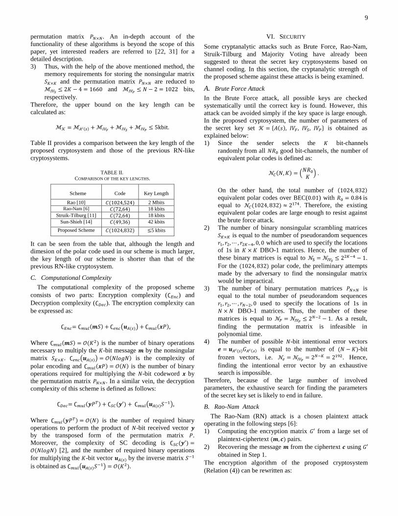
Table II provides a comparison between the key length of the
proposed cryptosystem and those of the previous RN-like
cryptosystems.
TABLE II. COMPARISON OF THE KEY LENGTHS.
Scheme
Code
Key Length
Rao [10] ( ) 2 Mbits
Rao-Nam [6] ( ) 18 kbits
Struik-Tilburg [11] ( ) 18 kbits
Sun-Shieh [14] ( ) 42 kbits
Proposed Scheme ( ) 5 kbits
It can be seen from the table that, although the length and
dimesion of the polar code used in our scheme is much larger,
the key length of our scheme is shorter than that of the
previous RN-like cryptosystem.
C. Computational Complexity
The computational complexity of the proposed scheme
consists of two parts: Encryption complexity ( ) and
Decryption complexity ( ). The encryption complexity can
be expressed as:
( ) ( ( )) ( ),
Where ( ) ( ) is the number of binary operations
necessary to multiply the -bit message by the nonsingular
matrix . ( ( )) ( ) is the complexity of
polar encoding and ( ) ( ) is the number of binary
operations required for multiplying the -bit codeword by
the permutation matrix . In a similar vein, the decryption
complexity of this scheme is defined as follows:
( ) (
) ( ( ) ),
Where ( ) ( ) is the number of required binary
operations to perform the product of -bit received vector
by the transposed form of the permutation matrix .
Moreover, the complexity of SC decoding is ( )
( ) [2], and the number of required binary operations
for multiplying the -bit vector ( ) by the inverse matrix
is obtained as ( ( ) ) ( ).
VI. SECURITY
Some cryptanalytic attacks such as Brute Force, Rao-Nam,
Struik-Tilburg and Majority Voting have already been
suggested to threat the secret key cryptosystems based on
channel coding. In this section, the cryptanalytic strength of
the proposed scheme against these attacks is being examined.
A. Brute Force Attack
In the Brute Force attack, all possible keys are checked
systematically until the correct key is found. However, this
attack can be avoided simply if the key space is large enough.
In the proposed cryptosystem, the number of parameters of
the secret key set { ( ) } is obtained as
explained below:
1) Since the sender selects the bit-channels
randomly from all good bit-channels, the number of
equivalent polar codes is defined as:
( ) (
) .
On the other hand, the total number of ( )
equivalent polar codes over BEC( ) with is
equal to ( ) . Therefore, the existing
equivalent polar codes are large enough to resist against
the brute force attack.
2) The number of binary nonsingular scrambling matrices
is equal to the number of pseudorandom sequences
which are used to specify the locations
of 1s in DBO-1 matrices. Hence, the number of
these binary matrices is equal to .
For the ( ) polar code, the preliminary attempts
made by the adversary to find the nonsingular matrix
would be impractical.
3) The number of binary permutation matrices is
equal to the total number of pseudorandom sequences
used to specify the locations of 1s in
DBO-1 matrices. Thus, the number of these
matrices is equal to . As a result,
finding the permutation matrix is infeasible in
polynomial time.
4) The number of possible -bit intentional error vectors
( ) ( ) is equal to the number of ( )-bit
frozen vectors, i.e. . Hence,
finding the intentional error vector by an exhaustive
search is impossible.
Therefore, because of the large number of involved
parameters, the exhaustive search for finding the parameters
of the secret key set is likely to end in failure.
B. Rao-Nam Attack
The Rao-Nam (RN) attack is a chosen plaintext attack
operating in the following steps [6]:
Computing the encryption matrix from a large set of 1)
plaintext-ciphertext ( ) pairs.
Recovering the message from the ciphertext using 2)
obtained in Step 1.
The encryption algorithm of the proposed cryptosystem
(Relation (4)) can be rewritten as:

10
( ) ( ) ( )
, (5)
where [ ] is an encryption
matrix and (
) is the permuted intentional
error vector. Let and be two -bit plaintext vectors
differing only in the -th, position. Let
and
be two distinct -bit ciphertext
vectors achieved from the plaintexts and , respectively.
The difference vector of is thus computed as:
( ) (
)
(
).
Besides, the -th row of the encryption matrix is
achievable through the following equation:
(
). (6)
It is obvious that the Hamming weight of (
) is at
most ( ), where (
) is the Hamming weight of the
permuted error vector . Since the matrix is a permutation
matrix, ( ) ( ). If ( ) ⁄ , the difference
vector represents one estimate of . This procedure
should be followed for all to obtain the
encryption matrix .
In the following, the required number of binary operations
(work factor) for constructing the encryption matrix is
being computed. Let and be
two distinct -bit ciphertexts of the proposed scheme obtained
from the same message . The difference between and is
calculated as
. This process should be tested
until one of the values obtained for
satisfies (6). Note
that the complete construction of encryption matrix must be
verified, as the correctness of each vector cannot be verified
independently. Since the number of distinct error vectors of
this scheme is equal to , the number of all possible
pairs ( ) is equal to (
) (
) ⁄ . In addition, the
vector should be computed for each of the rows of , so
that the work factor of this attack is computed as
(
)
. For , the work factor is obtained as
( ( ) ) [6]. Obviously, this attack is infeasible for the
proposed cryptosystem given the fact that the number of error
vectors, , is too large.
Furthermore, Rao and Nam claimed that this attack can also
be resisted by applying the set of intentional error vectors with
a Hamming weight of ( ) ⁄ [6]. Later, Meijers and
Tilburg [28] showed that the RN cryptosystem is vulnerable
to Extended Majority Voting (EMV) attack due to the
constraint on the Hamming weight of the intentional error
vectors. In fact, the predefined set of error vectors has to be
chosen at random. In the proposed scheme, there is not any
constraint on the Hamming weight of the intentional error
vectors which in turn improves the security.
C. Struik-Tilburg Attack
Let { } and { } denote a
set of distinct error vectors and their permuted error vectors,
respectively. Also, consider { } as a set of difference intentional error vectors. Similarly,
{ } is the set of difference permuted
intentional error vectors. Since there are distinct permuted
error vectors, the set of distinct ciphertexts is obtained as
{ }. The performance of the
Struik-Tilburg (ST) attack is described in the following steps
[11]: First, an arbitrary message is enciphered so that a set 1)
is yielded.
A directed labeled graph ( ) is constructed 2)
whose vertices consist of different ciphertexts and
each edge from vertex to vertex is labeled as the
difference permuted intentional error vector
. Afterwards, an automorphism group ( ) is
constructed, consisting of all the permutations on in
which all the edges remained unchanged. Hence,
the cardinality of the automorphism group is | ( ) |
.
For , a message is selected where 3)
is a unit vector with one ‘1’ in its -th position and the
rest 0s. Next, steps 1 and 2 are repeated for to
construct a set of its corresponding ciphertexts ( )
{ ( )
( ) } and its
directed label graph ( ( ) ).
For , an automorphism is selected randomly 4)
from the automorphism group ( ). Then, is
mapped on according to the selected automorphism .
Now, ( )
( )
( )
is calculated. As there exists an automorphism for
which ( )
, the -th row of the encryption matrix, ,
is estimated with the probability | ( )| .
Finally, using the estimated , the encryption 5)
matrix (
) is generated. If the solution is
not correct, the steps 4 and 5 should be repeated.
As mentioned earlier, the -th row of the encryption matrix,
, can be successfully estimated with the probability
| ( )| . In this case, the attacker should construct
| ( )| encryption matrices to finally obtain the
intended encryption matrix . Therefore, obtaining the
encryption matrix requires the work factor of ( )
operations. Apparently, if the value of | ( )| is large
enough, this attack ends in failure. In our scheme, for a
( ) non-systematic polar code over ( ), there are
| ( )| intentional error vectors, implying that the ST
attack is doomed to fail.
D. Majority Voting Attack
The Majority Voting (MV) is another kind of attack against
which the cryptanalytic strength of the secret key
cryptosystem based on channel coding has been analyzed [29].
An equivalent secret key cryptosystem to RN scheme is

11
introduced in [28, 29] to be able to examine the strength of the
RN scheme against MV attack.
Let [ ] be a binary
equivalent encryption matrix with a right inverse ( ) . Let
be a corresponding binary ( ) parity check matrix
such that . Moreover, { } is a set of
-bit intentional error vectors satisfying the weight property
and the syndrome property of the RN cryptosystem. Finally,
the syndrome error table is constructed as { | }.
Encryption
A -bit message is encrypted into an -bit ciphertext
by calculating .
Decryption
A ciphertext is decrypted as following the steps below:
Compute the syndrome . 1)
Find the corresponding error vector from the syndrome
error table .
Retrieve the message ( )( ) . 2)
The aim of the MV attack is to recover the equivalent
encryption matrix by following a number of procedures as
described below [29].
1) Choose an arbitrary plaintext , and compute a set of
distinct encryptions of , i.e. {
}. Let { } denote the set of distinct
-bit intentional error vectors. Then, compute ( )
( ) ( ) where ( ) is an matrix
consisting of the ciphertexts in its -th row,
respectively. Furthermore, ( ) is an matrix
where the -bit vector is repeated in each row.
Similarly, ( ) is an matrix consisting of the
intentional error vectors in its -th row,
respectively. The majority of the voting on each column
of ( ) yields an estimate , i.e. when 1s out
number 0s in a column, the corresponding bit is set to
ʻ1ʼ, and otherwise to ʻ0ʼ.
2) Repeat the first step for a set of linearly independent
messages and compute
3) Finally, obtain an estimate of the encryption matrix as
( ) ( ) where ( ) is a matrix
consisting of the -bit message in its -th
row. Besides, ( ) is a matrix consisting of the
estimates in its -th row. This way, the
estimate of the encryption matrix is obtained and used
to break the equivalent cryptosystem.
This attack requires times majority votes over
coordinates. Therefore, the work factor requires an average
number of ( ) bit operations [29]. Considering the worst
case, i.e. , this attack will have a work factor of
( ) bit operations. In the proposed cryptosystem,
because of the large number of intentional error vectors, the
work factor of this attack is ( ), which is regarded as an
evidence for the impracticality of the attack.
VII. CONCLUSIONS AND FUTURE WORK
The current paper was an attempt to address the issue of
applying non-systematic polar codes in the structure of secret
key cryptosystems. The proposed scheme enjoys a number of
advantages such as a higher security level and a shorter key
length in comparison with the previous secret key
cryptosystems based on channel coding. In addition, through
combining the encryption and channel coding in a single step,
this scheme has a potential to be implemented with a
reasonable complexity which is suitable for secure high speed
communications.
In this study, we employ the non-systematic polar codes due
to the following reasons: (1) Existing a large family of
equivalent polar codes which leads to an increase of the
security level against exhaustive search attacks. (2) The
special structure of the generator matrix of polar codes,
because of which the scheme achieves a smaller key size.
(3) The non-systematic property of polar codes, by which a
specific form of intentional error vectors is obtained that can
provide a higher security level against chosen plaintext attacks
and a smaller key length. (4) The low complexity encoding/
decoding of the polar codes. Moreover, the construction
method of these codes is simple over BECs.
The results of the investigations indicate that the security
and reliability of our scheme depend on a variety of factors
including the code length, code rate and secret information set.
Therefore, in order to design a secure and reliable secret key
scheme based on polar codes, these parameters should be
selected in such a way that a suitable tradeoff is established
between security and reliability.
Our future work is to apply the polar codes in the structure
of McEliece public key cryptosystem. However, it has to be
noted that reducing the key length of McEliece cryptosystem
based on polar codes is an interesting problem.
ACKNOWLEDGEMENT
The authors would like to thank Masoumeh Kootchak
Shooshtari and Behnam Mafakheri for their helpful
discussions and suggestions. The authors would also like to
thank Mahdi Alaghband for his careful proofreading.
REFERENCES
[1] S. Lin, D. J. Costello, Error control coding: fundamentals and
applications, 2nd ed., Upper Saddle River, NJ, Prentice-Hall, 2004. [2] E. Arıkan, “Channel polarization: A method for constructing capacity-
achieving codes for symmetric binary-input memoryless channels,”
IEEE Trans. Inf. Theory, vol. 55, no. 7, pp. 3051-3073, Jul. 2009. [3] A. Thangaraj, S. Dihidar, A. Calderbank, S. McLaughlin, J. M. Merolla,
ʻʻApplications of LDPC codes to the wiretap channel,” IEEE Trans. Inf.
Theory, vol. 53, no. 8, pp. 2933-2945, Aug. 2007. [4] H. Mahdavifar, A. Vardy, “Achieving the secrecy capacity of wiretap
channels using polar Codes,” IEEE Trans. Inf. Theory, vol. 57, issue. 10,
pp. 6428-6443, Oct. 2011. [5] R. J. McEliece, “A public-key cryptosystem based on algebraic coding
Theory,” DNS Progress Rep., Jet Propulsion Labaratory, CA, Pasadena,
pp. 114-116, 1978. [6] T. R. N. Rao, K. H. Nam, “Private-Key Algebraic-Code Encryption,”
IEEE Trans. Inf. Theory, vol. 35, no. 4, pp. 829-833, 1987. [7] D. J. Bernstein, J. Buchmann, E. Dahmen, Post-Quantum Cryptography,
Springer, 2008.

12
[8] E. R. Berlekamp, R. J. McEliece, H. C. A. van Tilborg, “On the Inherent
Intractability of Certain Coding Problems,” IEEE Trans. Inf. Theory,
vol. 24, no. 5, pp. 384-386, May 1978.
[9] T. Johansson, F. Jonsson, “On the complexity of some cryptographic
problems based on the general decoding problem,” IEEE Trans. Inf. Theory, vol. 48, pp. 2669-2678, Oct. 2002.
[10] T.R.N. Rao, “Joint encryption and error correction schemes,” in Proc.
11th annual Int. Symp. on Computer Architecture, Ann Arbor, Mich., 1984, pp. 240–241.
[11] R. Struik, J. van Tilburg, “The Rao-Nam scheme is insecure against a
chosen-plaintext attack,” in Advances in Cryptology - CRYPTOʼ87, New York: Springer-Verlag, 1987, pp. 445-457.
[12] A. Al Jabri, “Security of private-key encryption based on array codes,”
IEEE Electron. Lett., vol. 32, no. 24. pp. 2226-2227, 1996. [13] H. M. Sun, “Private key cryptosystem based on burst error correcting
codes,” IEEE Electron. Lett., vol. 33, no. 24, pp. 2035-2036, 1997.
[14] H. M. Sun, S. P. Shieh, “On private-key cryptosystems based on product codes,” in Proc. 3rd Australasian Conf. on Inf. Security and Privacy,
1998 pp. 68–79.
[15] A. I. Barbero, O. Ytrehus, “Modifications of the Rao-Nam
Cryptosystem,” in Proc. Int. Conf. on Coding Theory, Cryptography and
Related Areas, April 1998, pp. 1-13.
[16] A. Payandeh, M. Ahmadian, M. R. Aref, “Adaptive secure channel coding based on punctured turbo codes,” IEE Proc. Commun., vol. 153,
no. 2, pp. 313-316, April 2006.
[17] A. Payandeh, M. Ahmadian, M. R. Aref, “An Adaptive Secure Channel Coding Scheme for Data Transmission over LEO Satellite Channels,”
Scientica Iranica, vol. 13, no. 4, pp. 373-378, Oct. 2006. [18] A. A. SobhiAfshar, T. Eghlidos, M. R. Aref, “Efficient secure channel
coding based on quasi-cyclic low-density parity-check codes,” IET
Commun. Journals, vol. 3, pp. 279-292, 2009. [19] R. Hooshmand, T. Eghlidos, M.R. Aref, “Improving the Rao-Nam
Secret Key Cryptosystem Using Regular EDF-QC-LDPC Codes,”
ISeCure Journal, vol. 4, no. 1, pp. 3-14, Jan. 2012. [20] E. Hof, S. Shamai, “Secrecy-achieving polar-coding,” in Proc. IEEE Inf.
Theory Workshop, Sep. 2010, pp. 1-5.
[21] R. Hooshmand, M. K. Shooshtari, M.R. Aref, “Secret Key Cryptosystem based on Polar Codes over Binary Erasure Channel,” in Proc.
ISCISC2013, Yazd University, Iran, Aug. 2013, pp. 21-27.
[22] H. M. Sun, T. Hwang, “Key Generation of Algebraic-Code Cryptosystems,” Computers and Mathematics with Applications, vol. 27,
no. 2, pp. 99-106, 1994.
[23] N. Goela, S. B. Korada, M. Gastpar, “On LP decoding of polar codes,” in Proc. IEEE Inf. Theory Workshop, 2010, pp. 1-5.
[24] E. Arıkan, “A performance comparison of polar codes and Reed-Muller
codes,” IEEE Commun. Lett., vol. 12, pp. 447–449, June 2008. [25] E. Arıkan, “Systematic Polar Coding,” IEEE Commun. Lett., vol. 15, no.
8, pp. 860-862, Aug. 2011.
[26] S. B. Korada, A. Montanari, E. Telatar, R. Urbanke , “An emprical scaling law for polar codes,” in Proc. IEEE Int. Symp. Inf. Theory, 2010,
pp.884-888.
[27] A. Goli, S. H. Hassani, R. Urbanke, “Universal Bounds on the Scaling Behavior of Polar codes,” in Proc. IEEE Int. Symp. Inf. Theory, 2012,
pp. 1957-888.
[28] J. Meijers, J. V. Tilburg, “Extended Majority Voting and Private-Key
Algebraic Code Encryptions,” in Proc. ASIACRYPT’91, vol. 739
Fujiyoshida, Japan, Nov. 1991, pp. 288-298.
[29] J. van Tilburg, “Security-Analysis of a Class of Cryptosystems Based on Linear Error-Correcting Codes,” Ph.D. dissertation, Tech. Univ.
Eindhoven, Eindhoven, The Netherlands, 1994.
[30] T. Hwang, T. R. N. Rao, “Secret Error-Correcting Codes (SECC),” in Proc. CRYPTO'88, vol. 403, Santa Barbara, California, USA, August
1988, pp. 540-563.
[31] H. M. Sun, T. Hwang, “One Double-One Matrices and Double-Zero Matrices,” Linear and Multilinear Algebra, vol. 31, pp. 47-55, 1992.
Recommended