Secondary Reformer Refractory Dry Out
Operation
Prem Baboo DGM (Production & Process)
Abstract:- Secondary reformer refractory baking and
dry out cycle requires very slow and controlled heating
of refractory. Thermal stresses will be produced if
heating rate is too rapid. Longer period of low
temperature drying causes more even heat distribution
resulting better refractory dry out. It is very much
important that proper dry out of secondary reformer
refractories as water is the common solvent for mixing
refractory material. This article covers problems faced
during drying out operation is described present
information to better explain when there is a need for a
refractory dryout and the critical aspects. The changes
in temperature can have catastrophic effects on
refractory systems. This has sometimes led to refractory
failure before reaching normal operating conditions or
premature deterioration of lining systems leading to
unexpected, time consuming repairs required before or
during scheduled outages. One cannot fault a calculated
risk to get a unit back into production, but many times
these decisions are made by those not even aware they
are exposing a piece of equipment to any abnormal
risk.It is therefore imperative that all parties work
closely together to ensure a proper dryout, which
ultimately maximizes the performance of the refractory
lining in the application for which it was designed.
Keyword: -Refractory, Drying out, burner, CNG.
Secondary Reformer.
INTRODUCTION
Dangote Fertilizer Project consists in the realization of an
Ammonia and Urea complex with associated facilities. The
Project under progress at LEKKI Free Zone in Ibeiju-Lekki
Local Government Area of Lagos State, Nigeria. The
Dangote group is a Nigerian multinational industrial
conglomerate, founded by Aliko Dangote. It is the Largest
Conglomerate in the West Africa and one of the largest in
the African Continent.Ammonia and Urea complex
includes:
2x2200 MTPD Ammonia Trains based on HTAS technology
(and BASF technology for CO2 capture in Ammonia Plants).
2x3850 MTPD Melt Urea Trains based on Saipem
Technology.
2x3850 MTPD Urea Granulation Trains based on Udhe
Fertilizer technology. Associated Utility Units.
Commissioning activities under progress in train-1 plant in
which Ammonia Train-1 & 2 Secondary reformer drying
out operation has been successfully completed. However
problem faced in drying out operation in train -1
successfully rectified in Train-2.
AMMONIA PLANT BRIEF DESCRIPTION
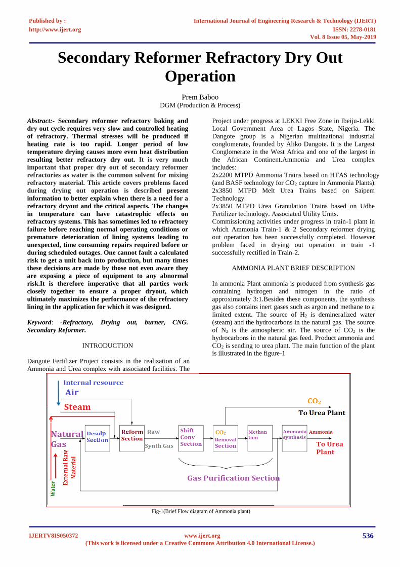
In ammonia Plant ammonia is produced from synthesis gas
containing hydrogen and nitrogen in the ratio of
approximately 3:1.Besides these components, the synthesis
gas also contains inert gases such as argon and methane to a
limited extent. The source of H2 is demineralized water
(steam) and the hydrocarbons in the natural gas. The source
of N2 is the atmospheric air. The source of CO2 is the
hydrocarbons in the natural gas feed. Product ammonia and
CO2 is sending to urea plant. The main function of the plant
is illustrated in the figure-1
Fig-1(Brief Flow diagram of Ammonia plant)
International Journal of Engineering Research & Technology (IJERT)
ISSN: 2278-0181http://www.ijert.org
IJERTV8IS050372(This work is licensed under a Creative Commons Attribution 4.0 International License.)
Published by :
www.ijert.org
Vol. 8 Issue 05, May-2019
536
The hydrocarbon feed is desulphurized to the ppb level in
the desulphurization section. The desulphurized
hydrocarbon feed is reformed with steam and air into raw
synthesis gas (process gas). The gas contains mainly
hydrogen, Nitrogen, Carbon monoxide, Carbon dioxide and
steam. In the gas purification section, the CO is first
converted into CO2. Then the CO2 is removed from the
process gas in the CO2 removal section. The CO and CO2
residues in the gas outlet of the CO2 removal unit are
converted into methane by reaction with H2 (methanation)
before the synthesis gas is sent to the ammonia synthesis
loop. The purified synthesis gas is compressed and then
routed to the ammonia synthesis loop, where it is converted
into ammonia. In order to limit the accumulation of argon
and methane in the loop, a purge stream is taken. The liquid
ammonia product is depressurised during which the
dissolved gases, let-down gas and inert gas, are flashed off.
REFORMER BRIEF DECRIPTION
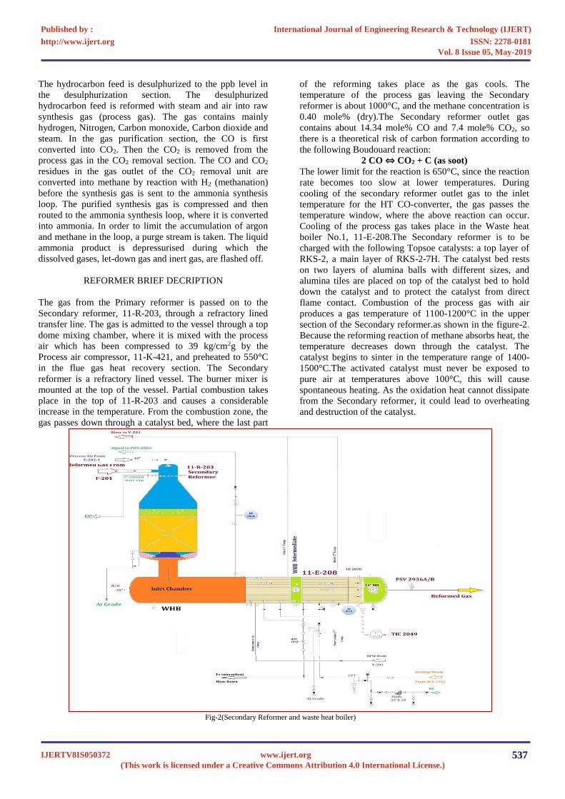
The gas from the Primary reformer is passed on to the
Secondary reformer, 11-R-203, through a refractory lined
transfer line. The gas is admitted to the vessel through a top
dome mixing chamber, where it is mixed with the process
air which has been compressed to 39 kg/cm2g by the
Process air compressor, 11-K-421, and preheated to 550°C
in the flue gas heat recovery section. The Secondary
reformer is a refractory lined vessel. The burner mixer is
mounted at the top of the vessel. Partial combustion takes
place in the top of 11-R-203 and causes a considerable
increase in the temperature. From the combustion zone, the
gas passes down through a catalyst bed, where the last part
of the reforming takes place as the gas cools. The
temperature of the process gas leaving the Secondary
reformer is about 1000°C, and the methane concentration is
0.40 mole% (dry).The Secondary reformer outlet gas
contains about 14.34 mole% CO and 7.4 mole% CO2, so
there is a theoretical risk of carbon formation according to
the following Boudouard reaction:
2 CO ⇔ CO2 + C (as soot)
The lower limit for the reaction is 650°C, since the reaction
rate becomes too slow at lower temperatures. During
cooling of the secondary reformer outlet gas to the inlet
temperature for the HT CO-converter, the gas passes the
temperature window, where the above reaction can occur.
Cooling of the process gas takes place in the Waste heat
boiler No.1, 11-E-208.The Secondary reformer is to be
charged with the following Topsoe catalysts: a top layer of
RKS-2, a main layer of RKS-2-7H. The catalyst bed rests
on two layers of alumina balls with different sizes, and
alumina tiles are placed on top of the catalyst bed to hold
down the catalyst and to protect the catalyst from direct
flame contact. Combustion of the process gas with air
produces a gas temperature of 1100-1200°C in the upper
section of the Secondary reformer.as shown in the figure-2.
Because the reforming reaction of methane absorbs heat, the
temperature decreases down through the catalyst. The
catalyst begins to sinter in the temperature range of 1400-
1500°C.The activated catalyst must never be exposed to
pure air at temperatures above 100°C, this will cause
spontaneous heating. As the oxidation heat cannot dissipate
from the Secondary reformer, it could lead to overheating
and destruction of the catalyst.
Fig-2(Secondary Reformer and waste heat boiler)
International Journal of Engineering Research & Technology (IJERT)
ISSN: 2278-0181http://www.ijert.org
IJERTV8IS050372(This work is licensed under a Creative Commons Attribution 4.0 International License.)
Published by :
www.ijert.org
Vol. 8 Issue 05, May-2019
537
The balance between reforming done in the Primary and
Secondary reformers depends on preheat temperatures and
the methane leakage. In practice the firing in the Primary
reformer is adjusted so that the desired outlet conditions from
the Secondary reformer are obtained with the amount of
process air required to give a hydrogen/nitrogen ratio of
approx. 3 to 1 in the synthesis gas to the loop. The high
temperatures in the Primary and especially in the Secondary
reformer necessitate chemical resistivity of the catalysts and
of the Secondary reformer lining. HTAS particularly
emphasize the use of catalysts free from silica and alkali, and
lining with a very low content of silica, as volatile
compounds otherwise will be carried out of the unit and
deposited on the Waste heat boiler surfaces. The process gas
leaves the reforming section at about 1000°C. It is cooled to
about 360°C in the Waste heat boiler, 11-E-208, where 120
kg/cm2g saturated steam is produced. After cooling, the gas
flows to the HT CO-converter, 11-R-204.
DRY OUT OPERION DESCRIPTION
The most critical factor that can affect the cast refractory
lining's lifespan is the refractory dry-out. This is the last stage
in the installation process, and carries over into the start of
operation and production during the commissioning phase.
The objective of the carry-over is to bring the refractory
lining to a condition suitable to commence operation. It is not
possible to recommend a standard dry-out schedule to meet
all conditions. Due to the variability of the products, their
water contents, and their final desired properties it is crucial
that the dry-out procedure, also known as the heat-up
schedule, is obtained from the refractory manufacturer for
that particular material and that it is followed strictly. The
engineering and operation of any refractory drying out is a
complex discipline that requires a detailed knowledge of the
operation, together with a knowledge of the available source
materials and their reliabilities such that temperature
monitoring, controlling of the temperature available
LPG/CNG etc. Although the environment on site may make it
difficult to achieve ideal operational conditions, steps can be
taken to counteract the detrimental effects. Curing times and
temperatures are also important to the cast lining life. It is
important to allow for a 12-24 hour curing time to allow for
the full hydration of the calcium aluminate binder. Loss of
water from the surface of the cast before the cement is fully
hydrated results in a weaker cast. If the material dries out
before the cement has had time to fully hydrate, the castable
strength will be reduced significantly. Dry out is the initial
heating of castable lining in order to remove retained water
from within the refractory castable without adversely
affecting its structure or physical properties. The secondary
reformer having monolithic refractory material contain water
or water based liquid which are needed to place the material
and help the setting process. Some of the water is chemically
bonded in the crystal structure of the binder and some of the
water is free water that was used a placement aid. All
monolithic refractory binder system is similar in this regards.
They are only different regarding the total amount of water.
The quantity of free versus chemically bonded and a potential
solid content that was dissolved in the liquid.
PREPARATION OF DRY OUT SECONDARY
REFORMER & WASTE HEAT BOLER INLET CHAMBER
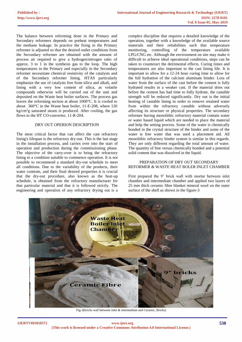
First prepared the 9’ brick wall with mortar between inlet
chamber and intermediate chamber and applied two layers of
25 mm thick ceramic fibre blanket mineral wool on the outer
surface of the shell as shown in the figure-3
Fig-3(bricks wall between inlet & intermediate and Ceramic, Bricks)
International Journal of Engineering Research & Technology (IJERT)
ISSN: 2278-0181http://www.ijert.org
IJERTV8IS050372(This work is licensed under a Creative Commons Attribution 4.0 International License.)
Published by :
www.ijert.org
Vol. 8 Issue 05, May-2019
538
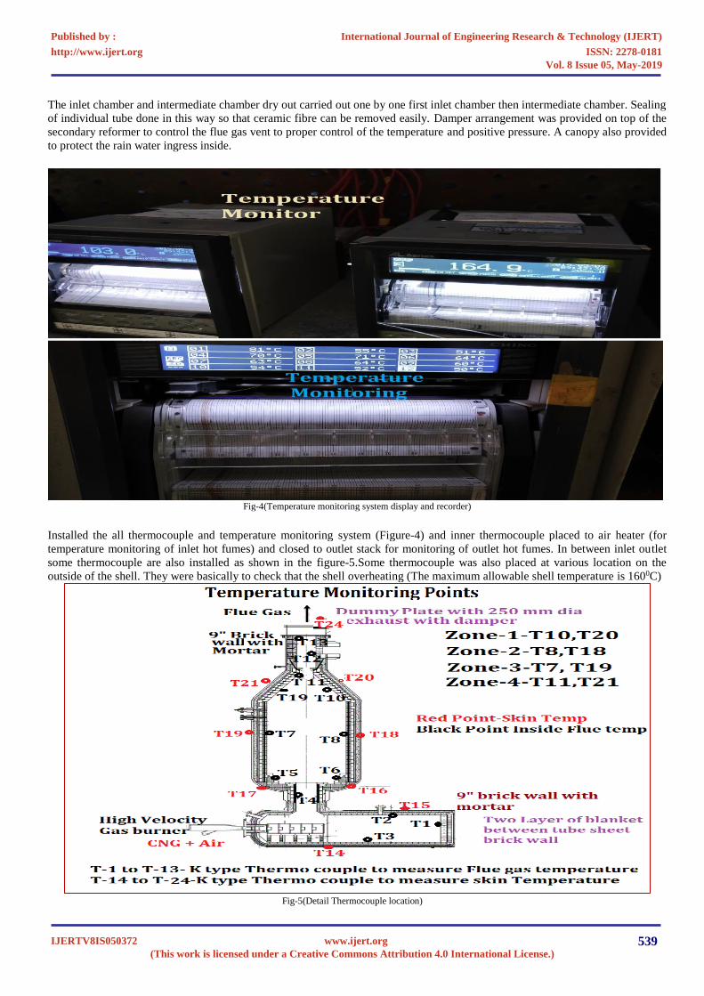
The inlet chamber and intermediate chamber dry out carried out one by one first inlet chamber then intermediate chamber. Sealing
of individual tube done in this way so that ceramic fibre can be removed easily. Damper arrangement was provided on top of the
secondary reformer to control the flue gas vent to proper control of the temperature and positive pressure. A canopy also provided
to protect the rain water ingress inside.
Fig-4(Temperature monitoring system display and recorder)
Installed the all thermocouple and temperature monitoring system (Figure-4) and inner thermocouple placed to air heater (for
temperature monitoring of inlet hot fumes) and closed to outlet stack for monitoring of outlet hot fumes. In between inlet outlet
some thermocouple are also installed as shown in the figure-5.Some thermocouple was also placed at various location on the
outside of the shell. They were basically to check that the shell overheating (The maximum allowable shell temperature is 1600C)
Fig-5(Detail Thermocouple location)
International Journal of Engineering Research & Technology (IJERT)
ISSN: 2278-0181http://www.ijert.org
IJERTV8IS050372(This work is licensed under a Creative Commons Attribution 4.0 International License.)
Published by :
www.ijert.org
Vol. 8 Issue 05, May-2019
539
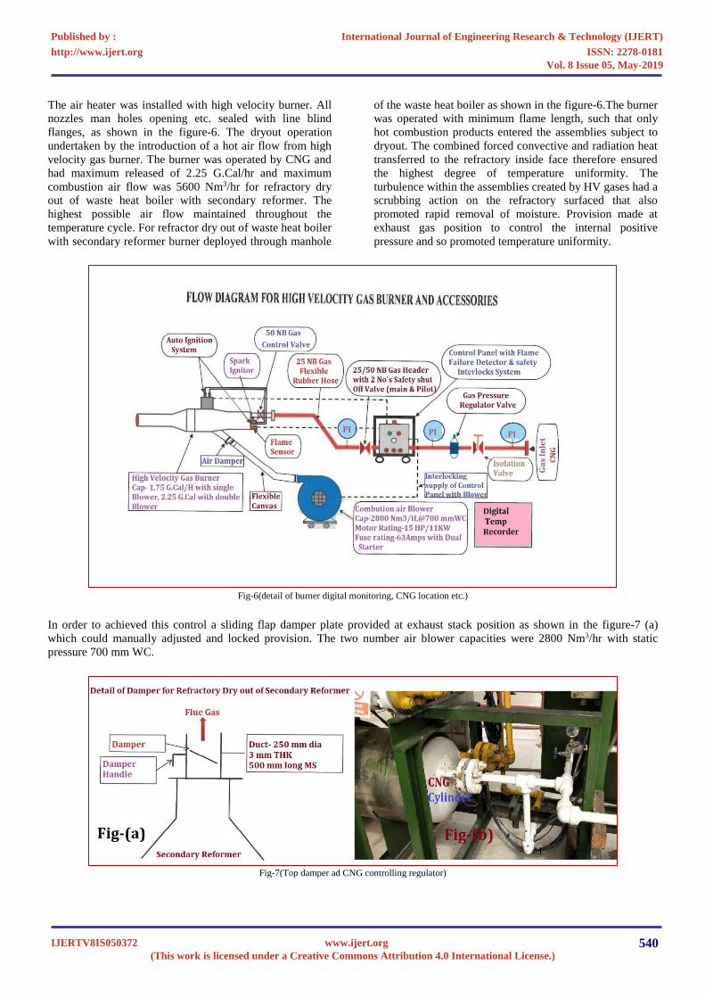
The air heater was installed with high velocity burner. All
nozzles man holes opening etc. sealed with line blind
flanges, as shown in the figure-6. The dryout operation
undertaken by the introduction of a hot air flow from high
velocity gas burner. The burner was operated by CNG and
had maximum released of 2.25 G.Cal/hr and maximum
combustion air flow was 5600 Nm3/hr for refractory dry
out of waste heat boiler with secondary reformer. The
highest possible air flow maintained throughout the
temperature cycle. For refractor dry out of waste heat boiler
with secondary reformer burner deployed through manhole
of the waste heat boiler as shown in the figure-6.The burner
was operated with minimum flame length, such that only
hot combustion products entered the assemblies subject to
dryout. The combined forced convective and radiation heat
transferred to the refractory inside face therefore ensured
the highest degree of temperature uniformity. The
turbulence within the assemblies created by HV gases had a
scrubbing action on the refractory surfaced that also
promoted rapid removal of moisture. Provision made at
exhaust gas position to control the internal positive
pressure and so promoted temperature uniformity.
Fig-6(detail of burner digital monitoring, CNG location etc.)
In order to achieved this control a sliding flap damper plate provided at exhaust stack position as shown in the figure-7 (a)
which could manually adjusted and locked provision. The two number air blower capacities were 2800 Nm3/hr with static
pressure 700 mm WC.
Fig-7(Top damper ad CNG controlling regulator)
International Journal of Engineering Research & Technology (IJERT)
ISSN: 2278-0181http://www.ijert.org
IJERTV8IS050372(This work is licensed under a Creative Commons Attribution 4.0 International License.)
Published by :
www.ijert.org
Vol. 8 Issue 05, May-2019
540
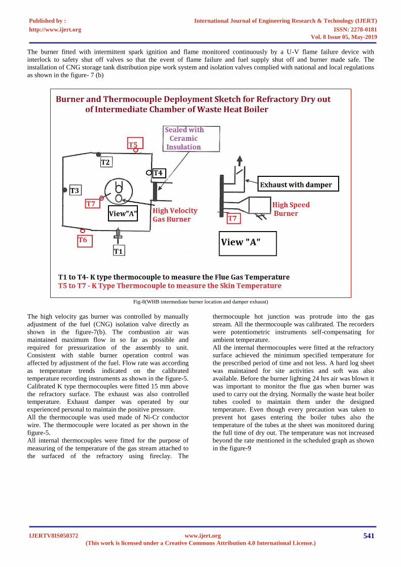
The burner fitted with intermittent spark ignition and flame monitored continuously by a U-V flame failure device with
interlock to safety shut off valves so that the event of flame failure and fuel supply shut off and burner made safe. The
installation of CNG storage tank distribution pipe work system and isolation valves complied with national and local regulations
as shown in the figure- 7 (b)
Fig-8(WHB intermediate burner location and damper exhaust)
The high velocity gas burner was controlled by manually
adjustment of the fuel (CNG) isolation valve directly as
shown in the figure-7(b). The combustion air was
maintained maximum flow in so far as possible and
required for pressurization of the assembly to unit.
Consistent with stable burner operation control was
affected by adjustment of the fuel. Flow rate was according
as temperature trends indicated on the calibrated
temperature recording instruments as shown in the figure-5.
Calibrated K type thermocouples were fitted 15 mm above
the refractory surface. The exhaust was also controlled
temperature. Exhaust damper was operated by our
experienced personal to maintain the positive pressure.
All the thermocouple was used made of Ni-Cr conductor
wire. The thermocouple were located as per shown in the
figure-5.
All internal thermocouples were fitted for the purpose of
measuring of the temperature of the gas stream attached to
the surfaced of the refractory using fireclay. The
thermocouple hot junction was protrude into the gas
stream. All the thermocouple was calibrated. The recorders
were potentiometric instruments self-compensating for
ambient temperature.
All the internal thermocouples were fitted at the refractory
surface achieved the minimum specified temperature for
the prescribed period of time and not less. A hard log sheet
was maintained for site activities and soft was also
available. Before the burner lighting 24 hrs air was blown it
was important to monitor the flue gas when burner was
used to carry out the drying. Normally the waste heat boiler
tubes cooled to maintain them under the designed
temperature. Even though every precaution was taken to
prevent hot gases entering the boiler tubes also the
temperature of the tubes at the sheet was monitored during
the full time of dry out. The temperature was not increased
beyond the rate mentioned in the scheduled graph as shown
in the figure-9
International Journal of Engineering Research & Technology (IJERT)
ISSN: 2278-0181http://www.ijert.org
IJERTV8IS050372(This work is licensed under a Creative Commons Attribution 4.0 International License.)
Published by :
www.ijert.org
Vol. 8 Issue 05, May-2019
541
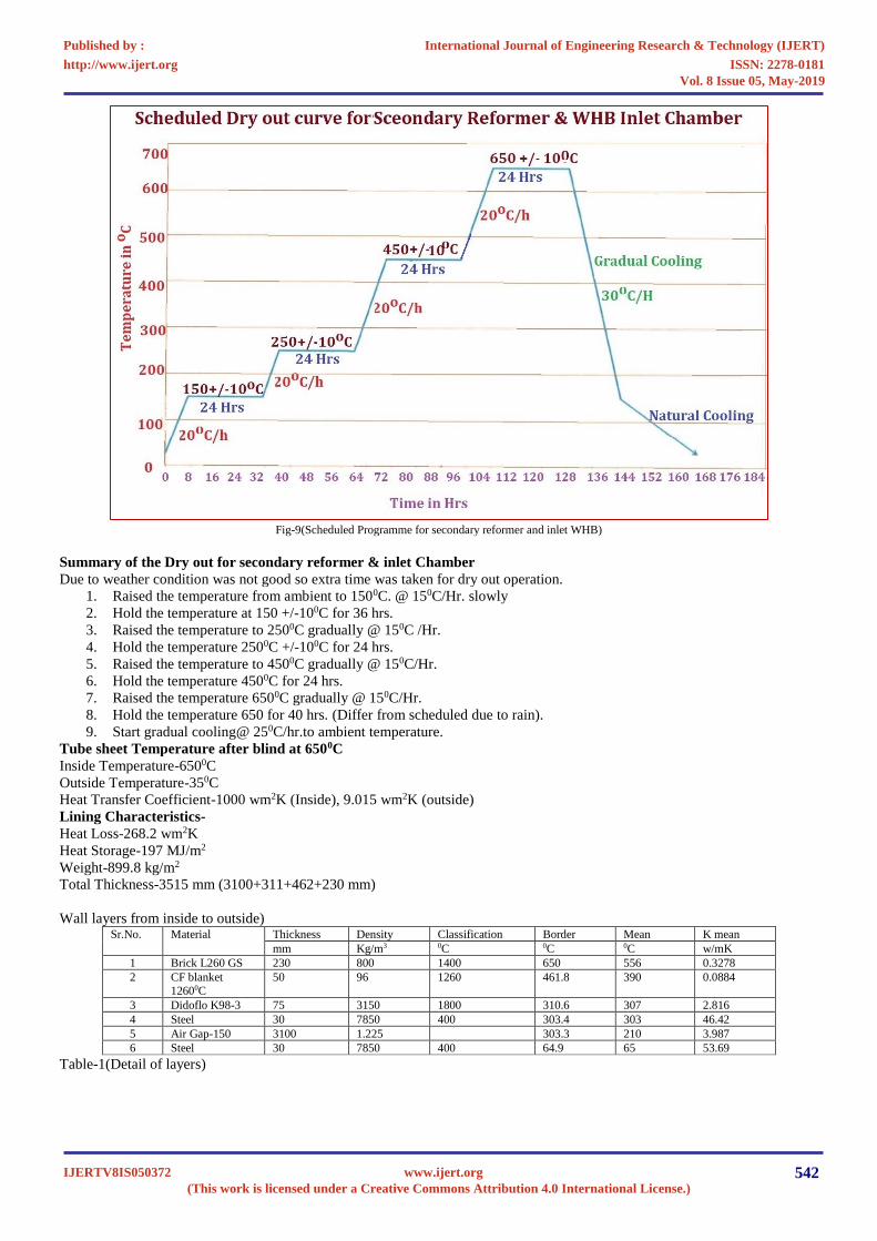
Fig-9(Scheduled Programme for secondary reformer and inlet WHB)
Summary of the Dry out for secondary reformer & inlet Chamber
Due to weather condition was not good so extra time was taken for dry out operation.
1. Raised the temperature from ambient to 1500C. @ 150C/Hr. slowly
2. Hold the temperature at 150 +/-100C for 36 hrs.
3. Raised the temperature to 2500C gradually @ 150C /Hr.
4. Hold the temperature 2500C +/-100C for 24 hrs.
5. Raised the temperature to 4500C gradually @ 150C/Hr.
6. Hold the temperature 4500C for 24 hrs.
7. Raised the temperature 6500C gradually @ 150C/Hr.
8. Hold the temperature 650 for 40 hrs. (Differ from scheduled due to rain).
9. Start gradual cooling@ 250C/hr.to ambient temperature.
Tube sheet Temperature after blind at 6500C
Inside Temperature-6500C
Outside Temperature-350C
Heat Transfer Coefficient-1000 wm2K (Inside), 9.015 wm2K (outside)
Lining Characteristics-
Heat Loss-268.2 wm2K
Heat Storage-197 MJ/m2
Weight-899.8 kg/m2
Total Thickness-3515 mm (3100+311+462+230 mm)
Wall layers from inside to outside) Sr.No. Material Thickness Density Classification Border Mean K mean
mm Kg/m3 0C 0C 0C w/mK
1 Brick L260 GS 230 800 1400 650 556 0.3278
2 CF blanket
12600C
50 96 1260 461.8 390 0.0884
3 Didoflo K98-3 75 3150 1800 310.6 307 2.816
4 Steel 30 7850 400 303.4 303 46.42
5 Air Gap-150 3100 1.225 303.3 210 3.987
6 Steel 30 7850 400 64.9 65 53.69
Table-1(Detail of layers)
International Journal of Engineering Research & Technology (IJERT)
ISSN: 2278-0181http://www.ijert.org
IJERTV8IS050372(This work is licensed under a Creative Commons Attribution 4.0 International License.)
Published by :
www.ijert.org
Vol. 8 Issue 05, May-2019
542
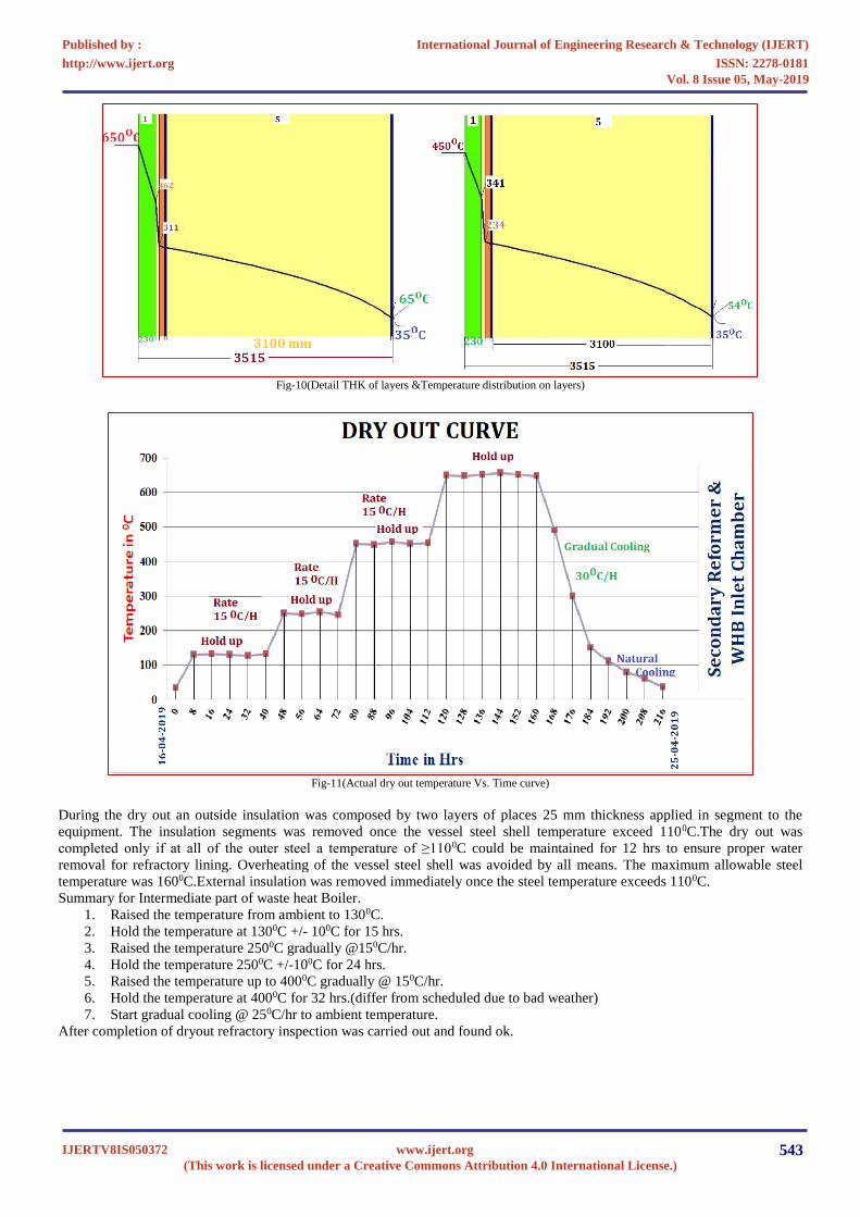
Fig-10(Detail THK of layers &Temperature distribution on layers)
Fig-11(Actual dry out temperature Vs. Time curve)
During the dry out an outside insulation was composed by two layers of places 25 mm thickness applied in segment to the
equipment. The insulation segments was removed once the vessel steel shell temperature exceed 1100C.The dry out was
completed only if at all of the outer steel a temperature of ≥1100C could be maintained for 12 hrs to ensure proper water
removal for refractory lining. Overheating of the vessel steel shell was avoided by all means. The maximum allowable steel
temperature was 1600C.External insulation was removed immediately once the steel temperature exceeds 1100C.
Summary for Intermediate part of waste heat Boiler.
1. Raised the temperature from ambient to 1300C.
2. Hold the temperature at 1300C +/- 100C for 15 hrs.
3. Raised the temperature 2500C gradually @150C/hr.
4. Hold the temperature 2500C +/-100C for 24 hrs.
5. Raised the temperature up to 4000C gradually @ 150C/hr.
6. Hold the temperature at 4000C for 32 hrs.(differ from scheduled due to bad weather)
7. Start gradual cooling @ 250C/hr to ambient temperature.
After completion of dryout refractory inspection was carried out and found ok.
International Journal of Engineering Research & Technology (IJERT)
ISSN: 2278-0181http://www.ijert.org
IJERTV8IS050372(This work is licensed under a Creative Commons Attribution 4.0 International License.)
Published by :
www.ijert.org
Vol. 8 Issue 05, May-2019
543
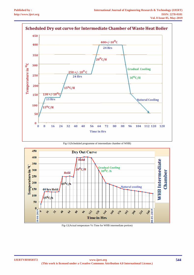
Fig-11(Scheduled programme of intermediate chamber of WHB)
Fig-12(Actual temperature Vs Time for WHB intermediate portion)
International Journal of Engineering Research & Technology (IJERT)
ISSN: 2278-0181http://www.ijert.org
IJERTV8IS050372(This work is licensed under a Creative Commons Attribution 4.0 International License.)
Published by :
www.ijert.org
Vol. 8 Issue 05, May-2019
544
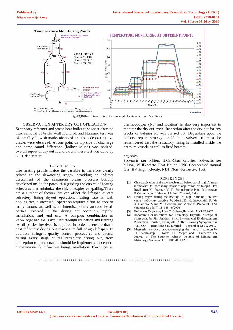
Fig-13(Different temperature thermocouple location & Temp Vs. Time)
OBSERVATION AFTER DRY OUT OPERATION-
Secondary reformer and waste heat boiler tube sheet checked
after removal of bricks wall found ok and Hammer test was
ok, small yellowish marks observed on tube side casting. No
cracks were observed. At one point on top side of discharge
end some sound difference (hollow sound) was noticed,
overall report of dry out found ok and these test was done by
NDT department.
CONCLUSION
The heating profile inside the castable is therefore clearly
related to the dewatering stages, providing an indirect
assessment of the maximum steam pressure buildup
developed inside the pores, thus guiding the choice of heating
schedules that minimize the risk of explosive spalling.There
are a number of factors that can affect the lifespan of cast
refractory lining dryout operation, heating rate as well
cooling rate, a successful operation requires a fine balance of
many factors, as well as an interdisciplinary attitude by all
parties involved in the drying out operation, supply,
installation, and end use. A complex combination of
knowledge and skills acquired through education and training
by all parties involved is required in order to ensure that a
cast refractory drying out reaches its full design lifespan. In
addition, stringent quality control procedures and checks
during every stage of the refractory drying out, from
conception to maintenance, should be implemented to ensure
a maximum-life refractory lining installation. Placement of
thermocouples (No. and location) is also very important to
monitor the dry out cycle. Inspection after the dry out for any
cracks or bulging etc was carried out. Depending upon the
defects repair strategy could be evolved. It must be
remembered that the refractory lining is installed inside the
pressure vessels as well as fired heaters.
Legends-
Ppb-parts per billion, G.Cal-Giga calories, ppb-parts per
billion, WHB-waste Heat Boiler, CNG-Compressed natural
Gas. HV-High velocity. NDT-Non- destructive Test.
REFERENCES [1] Characterisation of thermo-mechanical behaviour of high Alumna
refractories for secondary reformer application by Ranjan Dey,
Ravikumar N., Eswaran V. T., Sudip Kumar Paul, Rajagopalan
R.Carborundum Universal Limited, Chennai, India. [2] Drying stages during the heating of high Alumina ultra-low
cement refractory castable by Murilo D. M. Innocentini, Fa´bio
A. Cardoso, Mario M. Akyioshi, and Victor C. Pandolfelli J.M. ceramics Soc 86(7) 114648-48(2003)
[3] Refractory Dryout by Irbin C. Cobane,Hotwork, April 23,2002
[4] Important Considerations for Refractory Dryouts, Startups & Shutdowns by Jim Jenkins, Shell International Exploration and
Production, Houston, Texas, 2011 Sulfur Recovery Symposium in
Vail, CO. — Brimstone STS Limited — September 13-16, 2011. [5] Magnesia refractory dryout–managing the risk of hydration by
J.D. Steenkamp, H. Kotzé, J.G. Meyer, and J. Barnard* The
Journal of The Southern African Institute of Mining and Metallurgy Volume-111, JUNE 2011 423
*******************************************************************************
International Journal of Engineering Research & Technology (IJERT)
ISSN: 2278-0181http://www.ijert.org
IJERTV8IS050372(This work is licensed under a Creative Commons Attribution 4.0 International License.)
Published by :
www.ijert.org
Vol. 8 Issue 05, May-2019
545
Recommended