ESA 2019
2019
SEALING DEVICES REDUCTION OF FUGITIVE EMISSIONS DOCUMENT BEST AVAILABLE TECHNIQUES
ESA 2019
• CONTENTS
• SECTION 1. EXECUTIVE SUMMARY – PAGE 2
• SECTION 2. GENERAL INTRODUCTION TO THE SOURCES OF FUGITIVE
EMISSIONS AND EMISSION REDUCTION – PAGE 7
• SECTION 3. GASKETS USED IN SEALING FLANGED CONNECTIONS – PAGE 19
• SECTION 4. MECHANICAL SEALS USED IN ROTATING EQUIPMENT, SUCH AS
PUMPS, CENTRIFUGAL COMPRESSORS, AND AGITATORS/MIXERS – PAGE 29
• SECTION 5. PACKINGS USED IN VALVE STEMS AND ROTATING EQUIPMENT
– PAGE 44
• SECTION 6. ELASTOMERIC AND POLYMERIC SEALS – PAGE 57
• SECTION 7. FABRIC EXPANSION JOINTS – PAGE 67
• SECTION 8. METHODS OF MEASURING EMISSIONS ACCURATELY – PAGE 72
• SECTION 9. APPENDIX – REFERENCES – PAGE 81
ACKNOWLEDGEMENTS The ESA and FSA would like to acknowledge the input from members of both associations:
Francesco Apuzzo – Carrara Henri Azibert – FSA Daniel Craig Bissett – WLGore Peter Bowden - ESA Sandy van den Broeck - Donit Andrew Douglas – James Walker Jim Drago – Garlock David Edwin-Scott – ESA John Eves – James Walker Hans Vams Hansen – Eagle Burgmann David Mitchell – ESA John Morton – John Crane Kamesh Narayanaswamy – John Crane Mark Neal - ESA Ronald Noesel – Flowserve Christoph Nussel – Frenzelit Katherine Payne - Flexitallic Stefan Puchtler – Frenzelit Wolfgang Schopplein – ESA Ralf Vogel – Burgmann Packings Matt Wasielewski – Yarmouth Research and Technology Andreas Will - Frenzelit Rainer Zeuss – SGL

ESA 2019
2
SEALING DEVICES FUGITIVE EMISSIONS
REDUCTION DOCUMENT
NOTE: This document is a working version for the European IPPC Bureau (of the
Commission’s Joint Research Section). It focuses on the Industrial Emissions Directive (IED)
2010/75/EU and the part sealing devices play in the reduction of fugitive emissions. It is not an
official publication of the European Union and does not necessarily reflect the position of the
European Commission.
SECTION 1. Executive summary
The European Sealing Association (ESA) represents the majority of Sealing Product manufacturers in Europe. The ESA has over 50 members, with a combined turnover of Euros 2.6billion, and employs some 12,500 people. 50.6% are in manufacturing, 8.8% in R&D, and 25.9% in Sales and Marketing. The ESA works in very close co-operation with the Fluid Sealing Association (FSA) which represent the large majority of Sealing Product manufacturers in USA, Canada and Mexico.
This Sealing Devices Fugitive Emissions Reduction document reflects an information exchange
originally carried out within the sealing industry under Article 16(2) of Council Directive
96/61/EC. This update revision reflects the Industrial Emissions Directive (IED) 2010/75/EU
adopted on 24th November 2010 and implemented on 7th January 2013 and the Directive
2008/1/EC covering Integrated Pollution Prevention and Control (IPPC) which came into force
on 18th February 2008.
All details can be found in the various published Industrial Emissions Directive BAT Reference Documents (BREF) which all refer to Best Available Techniques (BATs) which are an integral part of all reference BREFs. This document is available on the BATIS system for all BREFs (special access is required via EIPPCB)
The IED covers the following industries as specified in existing BREFs:
• Energy industries (Power stations, Oil and Gas up and down stream);
• Metal industries (Foundries and Finishing processes);
• Mineral industries; (Mining)
• Chemical industries; (Organic and Inorganic, pharmaceutical)
• Waste management;
• New industries – like intensive livestock farming.
This Executive Summary is intended to be read in conjunction with the specific sealing device
chapters which are relevant for any particular source of emissions from industrial processes or
applications.
ESA 2019
3
For the purposes of BAT information exchange, this document has been divided into different sealing devices, and reflects the key areas where emissions are likely to occur on industrial sites which are likely to be covered by EU Industrial Emissions Directive (IED) 2010/75/EU.
IED 2010/75/EU
One of the main reasons given for the introduction of IED 2010/75/EU was the insufficient implementation of BATs, leading to limited progress in the prevention and reduction in fugitive industrial emissions, as well as limitations with regard to compliance, enforcement and environmental effectiveness.
Fugitive emissions are generally defined as those unplanned emissions from Industrial processes, as opposed to those planned via flares, chimneys, and safety relief valves.
It has not been possible to carry out a detailed information exchange on sealing technology used in every industrial process because the scope would be so large.
Consequently, this fugitive emissions reduction document contains a mixture of generic and detailed information on sealing devices used on typical industrial processes.
MAJOR CHANGES WITH THE INTRODUCTION OF THE IED 2010/75/EU CAN BE
BEST SUMMARIZED AS FOLLOWS:
Better regulation:
Merging of 7 existing directives (IPPC 1996/61/EC and 2008/1/EC); Large Combustion Plants
(2001/80/EC); Waste Incineration (2000/76/EC); Solvent Emissions (1999/13/EC); TiO2 x 3)
Strengthened provisions on:
• Inspections – article 23 – to be carried out every 3 years as an absolute minimum.
• Public access to information – article 24 and annex 1V
• Role of Best Available Techniques (BAT) in permitting of licenses for industrial plants:
• Definitions of BREF, BAT conclusions, and information exchange – articles 3, 13, and
annex 111
• Enhanced role of BREF, BAT conclusions, developments and Emissions limit values –
articles 14, 15, and 19
• Review of permit conditions – articles 4, 5, 12 and 14
IED scope for environmental issues:
Article 3 Definitions covers:
(2) Defines “Pollution”
(4) Defines “Emissions”
(5) Defines “Emission Limit Values” (ELV)
(10) Defines “Best Available Techniques”
(11) Defines “BAT reference documents”

ESA 2019
4
(12) Defines “BAT conclusions”
(13) Defines “Emission levels”
Article 14 confirms “Permit conditions”
The IED now covers the following aspects of the environment:
• Emissions to air – annex II
• Emissions to water – annex II
• Emissions to land
• Energy and Water use
• Waste prevention and recovery
• Prevention and control of accidents – article 7
• Noise
• Vibration
• Heat
• Odour
Essential requirements include:
• Achieve a high level of protection for the environment as a whole.
• Prevent pollution and, if not feasible, reduce pollution.
• Access to information and public participation - article 24 and annex IV
• Permit is required for operating the installation – article 4
Permit conditions include:
• Emission Limit Values (ELVs) for all relevant pollutants – listed in article 15
• ELVs based on the use of Best Available Techniques (BATs)
Article 13 BAT reference documents and exchange of information
The IED directives required that permit conditions would be based on best available techniques
(BATs) which are described in BAT reference documents (BREFs) which had been adopted by
the commission. Each BREF document contains specified BAT requirements which were to be
used as guidance for Competent Authorities when setting permit conditions.
Article 13 forum. The IED article 13 requires the commission to “organize an exchange of
information between member states, the industries concerned, non-governmental organisations
promoting environmental protection (like ESA) and the commission.”
The Article 13 forum is the working group for this process, which is often referred to the “Seville
Process”
A Technical Working Group (TWG) is set up by the Commission to draw up and or review a
BREF document. The Commission has published a timetable of BREF review work over the
next few years.
TWGs consists of Technical Experts representing member states; industry; Non-governmental
organisations (NGOs) promoting environmental protection; and the Commission. TWG
members are nominated based on their technical, economic, environmental and regulatory
expertise, as well as their ability to bring information into the BREF from an end user
perspective.

ESA 2019
5
It should be noted that the ESA is a full member of the Article 13 forum TWG, which is chaired by EU DG Environment, which acts as the sounding and steering board for BREF details and introduction. In particular this TWG is responsible for the guidance on the collection of data, the work programme for the exchange of information, and guidance in drawing up of BREFs and their quality assurance.
The role of BATs are to act as a reference for setting permit conditions (Article 14 (3)), and should contain the appropriate Emission Limit Values (ELV) (15 (3)), so that emissions never exceed BAT emission levels. Note BATs should be updated at least every 8 years.
IED 2010/75 requires that the Competent Authority MUST set emissions levels that did not
exceed those specified in the BAT conclusions adopted as a Commission Implementing
Decision, and ensure that these ELVs are not exceeded
Additional activities in IED annex. There are several amendments to the list of activities that are
now within the remit of the IED directive.
Soil Monitoring and remediation is a new requirement in the IED which requires periodic
monitoring of soil and groundwater.
There is a new requirement for the Competent Authority to provide for a system of environmental
inspections, and that all plants must have an inspection plan.
BAT CONCLUSION AND THE IMPORTANCE OF THE SEALING DEVICES
EMISSIONS REDUCTION DOCUMENT
ESA members manufacture the following products Sealing Devices that are essential in
achieving the aim of significantly reducing fugitive emissions to atmosphere.
Gaskets are used to provide a static seal between two stationary components. They are used
on flanges that connect piping, valves, compressors, pumps, instrumentation, and many other
types of equipment, like heat exchangers. Due to the high number of flanges and equipment
connections subject to the thermal and mechanical stresses associated with industrial
processes, the correct use of high performance gaskets can significantly contribute to reduced
fugitive emission levels. Gaskets come in several forms: Soft cut gaskets, semi metallic gaskets
and metallic gaskets. The selection of the correct gasket is vital and is usually made based on
chemical compatibility, temperature and pressure of the service.
Mechanical Seals which are used to seal rotating shafts as they enter the housing of pumps,
centrifugal compressors and agitators. The seals prevent gases and liquids from escaping in the
space where there is relative motion between the shaft and the housing. Various mechanical
seal technologies are used: Single spring seals, double seals, dry gas seals or wet oil seals all
with significantly different emission characteristics.
Compression Packing is most commonly made of braided fibres and is used to seal valve
stems and shafts of reciprocating compressors. Valves have been identified as a major
contributor to emissions, primarily due to their extremely high usage. Modern fibres and
construction methods allow sealing at extremely low emission levels.
Expansion Joints for Piping are used to provide a flexible connection between pipes flange
connections and other equipment. The use of expansion joints can reduce the number of piping
ESA 2019
6
connections, eliminate stress on a pipe that can create leaks in bolted joints, and reduce stress
on rotating equipment that could affect seal or bearing wear, thereby significantly contributing to
the reduction of emissions in piping systems.
Elastomeric and Polymeric Seals. Typically these are custom moulded or machined
components (including “O” ring seals) manufactured from a whole host of deformable and
resilient materials to seal liquids and gases in pressure containing systems. Frequently static
but are also used between parts in relative motion such as hydraulic cylinders or valve stems,
and continuous rotary motion such as marine and automotive drive shafts.
Summary. In short, where ever a pipe has to connect to a piece of plant equipment such as a
pump, valve or compressor several sealing devices are the component that contains the gases
or liquids and prevents the unplanned release of these substances.
THIS DOCUMENT FOCUSSES ON THE MAIN SOURCES OF FUGITIVE EMISSIONS TO THE
ATMOSPHERE, AND THE APPROPRIATE SEALING DEVICE TO COMBAT THESE MOST
EFFECTIVELY.
It cannot be overemphasized that Sealing Technology and Technician Training must both be taken extremely seriously to ensure that fugitive emissions from industrial processes are minimised. Training, in line with EN 1591 part 4 is available from ESA members and many other sources.
Training in the use of emissions measuring devices should also be considered to ensure accurate emissions measurement.

ESA 2019
7
SECTION 2. General introduction to Emission Reduction
using Sealing Devices
RELEVANT LEGAL OBLIGATIONS OF THE IED DIRECTIVE
The purpose of the Directive is to achieve integrated prevention and control of pollution
arising from the activities listed in its Annex 1, leading to a high level of protection of the
environment as a whole. The legal basis of the Directive relates to environmental protection.
Its implementation should also take account of other Community objectives such as the
competitiveness of the Community's industry thereby contributing to sustainable
development.
More specifically, it provides for a permitting system for certain categories of industrial
installations requiring both operators and regulators to take an integrated, overall look at the
polluting and consuming potential of the installation. The overall aim is to improve the
management and control of industrial processes so as to ensure a high level of protection for
the environment as a whole. Central to this approach is the general principle given in Article
11 that operators should take all appropriate preventative measures against pollution, in
particular through the application of best available techniques enabling them to improve their
environmental performance.
DEFINITION OF BAT
The term "best available techniques" is defined in Chapter I Article 3 of the Directive as "the most effective and advanced stage in the development of activities and their methods of operation which indicates the practical suitability of particular techniques for providing the basis for emission limit values and other permit conditions designed to prevent and, where that is not practicable, to reduce fugitive emissions and the impact on the environment as a whole."
Annex III of the Directive contains a list of "considerations to be taken into account
generally or in specific cases when determining best available techniques... bearing in
mind the likely costs and benefits of a measure and the principles of precaution and
prevention".

ESA 2019
8
This document can be considered the Sealing Industry BAT using the most modern
technology available in Sealing Devices
The key legal requirements of the IED Directive
Competent authorities responsible for issuing permits are required to take account of the
general principles set out in Articles 14 and 15 when determining the conditions of the permit.
These conditions must include fugitive emission limit values, supplemented or replaced where
appropriate by equivalent parameters or technical measures.
According to Article 15 of the Directive, these emission limit values, equivalent parameters and
technical measures must, without prejudice to compliance with environmental quality
standards, be based on the best available techniques, without prescribing the use of any
technique or specific technology but taking into account the technical characteristics of the
installation concerned, its geographical location and the local environmental conditions. In all
circumstances, the conditions of the permit must include provisions on the minimization of
long-distance or trans-boundary pollution (Article 26) and must ensure a high level of
protection for the environment as a whole. Member States have the obligation, according to
Article 19 of the Directive, to ensure that competent authorities follow or are informed of
developments in best available techniques.
OBJECTIVE OF THIS DOCUMENT
The aim of this document is to provide reference information for industrial sectors on
expected fugitive emission rates from sealing devices, to enable them to comply with the
requirements of the IED Directive.
The document also aims to provide reference information for appropriate permitting
authorities to take into account when determining permit conditions, and especially Emission
Limit Values
Specifically, by understanding the major sources of fugitive emissions on Industrial process
plants, and the available solutions provided by Sealing Technologies, the permitting authorities
and the process operators can make the most informed decisions on how best to prevent
emissions.
It should be noted that the techniques and solutions presented in each section will not
necessarily be appropriate for all installations.
On the other hand, the obligation to ensure a high level of environmental protection including
the minimization of long-distance or trans-boundary pollution implies that permit conditions
cannot be set on the basis of purely local considerations. Therefore, it is of the utmost
importance that the information contained herein is taken into account fully by permitting
authorities.

ESA 2019
9
Since the best available techniques inevitably will improve over time, this document will be
reviewed and updated as appropriate. All comments and suggestions should be made to the
European Sealing Association.
THE MAIN SOURCES OF INDUSTRIAL EMISSIONS
It is recognised that industry must reduce its impact on the environment if we are to continue
global development for future generations (the so-called “sustainable development” option). A
major contributory factor will be through the lowering of industrial emissions, which has been
catalysed by a combination of public pressure, environmental legislation and the internal
requirement to minimise the loss of valuable feed-stocks.
Large proportions of the emissions to atmosphere are represented by the by-products of
combustion (notably the oxides of carbon, nitrogen and sulphur), along with known losses of
volatile hydrocarbons and steam. In general, these are all emissions anticipated from the
industrial process, under the control of the plant operator.
However, a proportion of industrial emissions occurs through unanticipated or spurious
leaks in process systems. I t is clear that sealing systems play a vital role in the
environmental performance of industrial installations, and yet the sealing technology itself
is usually given scant consideration!
It must be emphasised that sealing technology can perform at its peak only after careful
selection (appropriate for the specific application), correct installation, and operation according
to the performance envelope, regular inspection and maintenance. These areas are the key
focus for this document.
The best available techniques for sealing technology are described, together with the
best practices for their selection, installation and use, in order to enable the plant
operator to achieve the requirements of the IED Directive.
FUGITIVE EMISSIONS
The term “fugitive emissions” covers all losses of (usually volatile) materials from a process
plant, through evaporation, flaring, spills and unanticipated or spurious leaks
To put the scale of the challenge into perspective, fugitive emissions in the USA have been
estimated to be in excess of 300,000 tonnes per year, accounting for about one third of the
total organic emissions from chemical plants, and these will inevitably be mirrored in
Europe.
A typical Oil Refinery will have a minimum of 20,000 flanged joints connected with pumps,
compressors, mixers, valves, level gauges, instruments, heat exchangers and vessels, all of
which are a potential leak source. Although losses per piece of equipment are usually very
small the total loss via fugitive routes may be very significant. For example, fugitive emissions
from European refineries range from 600 to 10000 tonnes of VOC’s per year. In some plants
ESA 2019
10
in the Netherlands, 72% of VOC emissions were attributed to leakage losses from equipment,
18% from flaring, 5% from combustion, 1% from storage and 4% from other process
emissions. In these plants, leakage is the greatest challenge and therefore it is crucial that
programmes are established to identify leak sources and to instigate actions to minimise them.
Many process streams in petrochemical refineries are “light” (containing at least 20% of
substances with a vapour pressure greater than 0.3 kPa at 20°C) and at high pressure (1500 -
3000 kPa), conditions which encourage fugitive losses. On the other hand, in some Aromatics
operations with lower operating temperatures and pressures and where the fluid vapour
pressures are lower, fugitive emissions are considerably less.
Irrespective of any environmental impact which it may cause, this is a tremendous
financial burden on industry because it represents a huge loss of potentially valuable
materials, and cause of plant inefficiency. Yet in most instances, the true costs are not
appreciated, since many of the costs associated with fugitive emissions are invisible.
The values of fugitive emissions will depend upon:
• Equipment design
• Age and quality of the equipment
• Standard of installation
• Vapour pressure of the process fluid
• Process temperature and pressure
• Number and type of sources
• Method of determination of emissions
• Inspection and maintenance routine
• Rate of production
Visible costs include the cost of the lost material. Invisible costs include, the cost of labour to repair the leak; materials to repair leaks; wasted energy; plant inefficiency; environmental "clean up"; environmental fines; lost sales due to poor image; and claims for personal injury.
Other European approaches to the control of fugitive emissions
Some EU Member States have introduced other legislation to control fugitive emissions, much
of which is complementary to the IED Directive and in some cases this may be necessary in
the transposition of the Directive into national legislation. On the other hand, some legislation
or guidelines have been introduced which go further than the IED Directive. These include the
latest refinements of the TA-Luft VDI 2440 on emission reduction in mineral oil refineries. The
reader is advised to refer to these items as appropriate.
Other country approaches to the control of fugitive emissions
Other parts of the world have their own rules and regulations to reduce the impact of fugitive
emissions.
North America in particular have strong rules under the EPA guidance. Canada, Mexico, and
U.S. states like California, Pennsylvania, Colorado, and Wyoming have all recently issued
regulations limiting the emission of Methane

ESA 2019
11
SOURCES OF FUGITIVE EMISSIONS
A significant proportion of fugitive emissions can be losses from unsealed sources, including storage tanks, open-ended (non- blanked) lines, pressure-relief valves, vents, flares, blow-down systems, spills and evaporation from water treatment facilities. These are part of the industrial process, anticipated (usually) by the process operator, and will not be considered further here.
In other cases, these losses may be caused by leaks in the sealing elements of particular
items of equipment, such as:
1. Valves. 50%-70%
2. Pumps. 10%3. Flanges. 5%4. Compressors. 3%5. Agitators / mixers. 2%
As unsealed point sources have become well controlled in recent years, equipment leaks
are often the greatest source of fugitive emissions. These equipment leaks are where the
sealing industry is playing a crucial role, through the development and application of
innovative sealing technology appropriate to low or zero emission requirements.
The primary purpose of a seal is to contain a fluid and so protect the immediate environment from contamination (and vice versa), which may vary in significance from innocuous fluid loss (such as steam, water, etc.) up to nauseous, toxic or hazardous fluid loss. In the former case, the loss of such innocuous fluid will lead primarily to lack of plant efficiency and financial loss
Valves60%
Tanks10%
Relief Valves15%
Flanges5%
Pumps10%
Chart Title
Valves Tanks Relief Valves Flanges Pumps

ESA 2019
12
for the operator, although some such leakages, of high pressure water or steam, may still present hazards.
It has been estimated that for every pump on an average plant, there will be 32 valves, 136
flanges, 1 safety valve and 1.5 open-ended lines. Hence, with so many potential sources,
leaking losses are often hard to determine. They are also very dependent on the age of the
equipment and how well the installation is maintained.
Some important causes of leaking losses are:
• Ill-fitting internal or external sealing elements
• Installation or construction faults
• Wear and tear
• Equipment failure
• Pollution of the sealing element
• Incorrect process conditions
• Competency of technicians operating and maintaining the equipment
Leaking losses are generally higher from dynamic equipment (compared with static equipment) and from older equipment.
Valves are considered to account for approximately 50-60% of fugitive emissions, due to the
numbers of valves found on a typical industrial plant. Furthermore the major proportion of
fugitive emissions comes from only a small fraction of the sources (e.g. less than 1% of valves
in gas / vapour service can account for more than 70% of the fugitive emissions in a refinery)
Some valves are more likely to leak than others such as:
• Valves with rising stems (gate valves, globe valves) are likely to leak to
atmosphere more frequently than quarter turn type valves such as ball, butterfly
and plug valves.
• Valves which are operated frequently, such as control valves, may wear quickly
and allow emission paths to develop. However, newer, low leak control valves
provide good fugitive emissions control performance.
Flanges represent approximately 5% of fugitive emissions on a plant despite the huge numbers of flanges found on most industrial plant.
A survey by the Pressure Research council in USA found that the common causes of flange
leakage are due to improper gasket installation (26%), Flange damage (25%), loose Bolts
(15%), and Flange misalignment (12%). Other common failures are bolt tension relaxation
issues, incorrect gasket selection for the service, including wrong gasket thickness and
corroded flange faces.
Typical achievable Emission Limit Values:
Using Methane gas as an example the following leakage rates using LDAR “sniffing” equipment
the following leakage could be expected:
• Valves: 50 ppmv now
• Flanges: 50 ppmv now with a target of 25 ppmv within 5 years

ESA 2019
13
• Pumps: 500 ppmv now with a target of 250ppmv in 5 years. Note these values refer to
pumps fitted with Single Seals, if fitted with Dual liquid or gas seals the emission rates
would be much lower.
• Centrifugal Compressors: 1000 ppmv now, with a target of 500ppmv within 5 years
EPA Document Protocol for Leak Emissions Estimates EPA-453/R-95-017 Nov 19
Energy use as a source of emissions.
It must also be remembered that energy is consumed whenever heating or pumping action is
applied to a process. This creates additional emissions at the power generation plant,
emphasising the need for utilising efficient pumping and heating technologies.
There are freely available programmes that can estimate accurately the Life Cycle Costs of
most equipment and sealing devices, taking into account the initial cost, the energy required to
operate the equipment, the cost of maintenance, and the cost of replacement.
Volatile Organic Compounds (VOC’s)
VOC’s emissions are of significant environmental concern because some have the potential for
Photochemical Ozone Creation Potential (POCP), Ozone Depletion Potential (ODP), Global
Warming Potential (GWP), toxicity, carcinogenicity and local nuisance from odour. The
prevention of VOC emissions is therefore one of the most important issues facing the operation
of many industrial processes.
VOC is the generic term applied to those organic carbon compounds which evaporate at
ambient temperature, and is defined usually as “a substance having a vapour pressure of
greater than 0.3 kPa at 20°C” (this is close to the US definition for the application limits of
systematic LDAR). The term covers a diverse group of substances and includes all organic
compounds released to air in the gas phase, whether hydrocarbons or substituted hydrocarbons.
Their properties, and hence need for control, vary greatly and so systems have been
developed to categorise VOC’s according to their harmfulness.
On many installations, there has been a focus on the control of point sources of VOC’s and
losses of fugitives as leaks (from pumps, valves, tanks etc.) have become the major source of
VOC emissions from many plants. This emphasises the importance of best available
techniques for sealing technology and reinforces the need for this document.
Technician training
There also needs to be a focus on the competency of the technicians tasked with fitting sealing
devices. This is fast becoming a very important issue with users. An example is in Germany,
where the new TA Luft regulations state that VDI 2290 is mandatory, and this means all
Technicians fitting sealing devices MUST pass a competency test. There are many accredited
Technician Training programmes available, including those provided by ESA and FSA
members.
EN 1591-4 also sets out the appropriate training, and standards that should be achieved by
technicians.
Leak Detection and Repair (LDAR) systems and programmes are also available, as is the
training of technicians to use these effectively (See SECTION 8)
ESA 2019
14
Importantly, the in-service performance and life of any sealing technology is very reliant upon
correct installation. As an example, the major cause of flange sealing failure is due to assembly
errors. Consequently:
Comprehensive training of all appropriate personnel on correct installation plays a vital
role in reducing Fugitive Emissions
PROCESS DESIGN
Operators should work to written standards and procedures when modifying existing installations
or designing new plant. As a minimum this should follow the requirements of any national and
international technical codes for materials, equipment design and fabrication. All design
decisions or modifications should be recorded in order to provide an audit trail. Environmental
protection should be an inherent feature of the design standards since techniques incorporated
at the design stage are both more effective and more economical. Initial process design should
consider how fundamental principles may be applied to process materials, process variables
and equipment in order to prevent releases. For example, consideration should be given to
identify opportunities for using new, low emission sealing developments or other appropriate
sealing technology options.
Other possible operational and maintenance techniques include:
• reverse the pressure gradient by operating the plant at below ambient pressure
(this is probably most feasible at the design stage)
• obviate the need for vessel opening through design modifications (e.g. cleaning
sprays) or change the mode of operation (e.g. spray anti-caking reagents directly
into vessels)
• convey leaks from compressor seals, vent and purge lines to flares or to
flameless oxidisers
• enclose effluent drainage systems and tanks used for effluent storage / treatment
MAINTENANCE
The maintenance of process plant and equipment is an essential part of good operation and will
involve both pro-active (preventative) and reactive approaches.
Preventative maintenance plays a very significant role in optimising environmental performance
and it is often the preferred approach. A structured programme of preventative maintenance
should be established after detailed consideration of equipment failure frequencies and
consequences. The maintenance programme should be supported by appropriate record
keeping systems and diagnostic testing. There should be clear responsibility for the planning
and execution of maintenance.
The need for reactive maintenance can be minimised by employee vigilance in relation to
imminent problems (e.g. process upsets and leaks). Leak Detection and Repair programmes
can also play an important role.
Equipment modifications during maintenance are a frequent occurrence on many plants and
should be covered by procedures which give authorisation only after a suitable level of risk
assessment. Subsequent process start-up should be dependent upon suitable post-modification
checks.

ESA 2019
15
MONITORING TO DETERMINE LEAKING LOSSES
Leaking losses are often hard to determine since there are many potential sources and they are
very dependent on how well the installation is operated, maintained and inspected. Some
important causes of leaking losses are:
• Ill-fitting sealing elements
• installation
• construction faults
• wear and tear
• ageing
• equipment failure
• contamination of the sealing element
• excursions out of normal process conditions
• poor maintenance procedures
Leaking losses are generally higher from dynamic equipment (compared with static equipment)
and from older equipment.
A structural reduction of leaking losses is only possible when insight on the leaking losses is
gained. There are various methods to determine the leaking losses. The simplest way to
estimate the leaking losses is by multiplying the number of each type of equipment by an
emission factor for that type of equipment. This method can be applied to obtain a general
estimation of the emissions without measurements. Emission factors are not intended as an
accurate measure of a single piece of equipment, and do not reflect the site-specific conditions
of process units.
Many companies determine their leaking losses by calculations or estimations based on
measurements, but it is hard to measure all possible sources in a large plant (possibly tens of
thousands) and not all sources are accessible. In most cases, a representative sampling of
sources will suffice to estimate or calculate the leaking losses of the plant. The number of
samples depends on the kind of process fluids in the plant and the kind of equipment (the
sources). However, to provide the best estimate of emissions, every potential “source” on a site
must be monitored (usually using a “sniffing” process such as that described in EPA Method
21).
Monitoring has been identified as a common activity across Industrial processes and is the
subject of a horizontal BREF note, entitled, “Monitoring of Emissions to Air and Water from IED
Installations ”. The document provides generic information on sampling and analysis and should
be read in conjunction with other industry-specific BREF notes. There is also a separate
section in this document on the measurement of leakages (See SECTION 8).
Monitoring is often expensive and time consuming, so the objectives should be clear when a
programme is established. Process operators and regulators may use monitoring to provide
information on a wide range of topics.
For this Emissions Reduction guidance note on sealing technologies, the key objectives of
monitoring are:
• Process control and optimisation; monitoring is the way used to control a process by
means of following-up significant physical and chemical parameters. By control of the
process, it is meant the application of conditions in which the process operates safely
and economically.
ESA 2019
16
• Emission monitoring; fugitive emissions to air and water are characterised and quantified
to provide a check on compliance with permit requirements (or other performance
measures). This also provides a check of whether all significant emissions are covered
by the permit and can indicate the effectiveness of abatement techniques and sealing
technologies employed. For the latter, emission monitoring can give an assessment of
leaking losses and will indicate equipment where attention is required. Wherever
possible, data should be collected on flow rates to enable the calculation of mass
discharges.
• Occupational health and safety; tests to identify the short and long term risks to personnel
from work place exposure.
• Troubleshooting; intensive, short duration programmes may be used to study specific
topics.
• A monitoring programme to address any of these topics will need to stipulate the
frequency, location and method of both sampling and analysis. Monitoring usually
involves precise quantitative analysis, but simple operator observations (either visually or
by smell) can also play an important role in the detection of abnormal releases. The
results of monitoring programmes should be actively utilised; records of results should be
kept for trend analysis and diagnostic use.
Some estimates have been made of the costs of monitoring schemes. For example, a simple
LDAR scheme, involving the annual inspection of gas and volatile liquid service components, is
estimated to have a net annualised cost of over €15K per year (for a typical plant handling
20000 tpa of gaseous hydrocarbon streams and 30000 tpa of volatile liquids).
A strategy to reduce VOC emissions may include a complete inventory and quantification by a
DIAL LIDAR technique (differential absorption light detection and ranging). In some cases,
emissions estimates using “sniffing” methods give lower emissions than estimates based on the
DIAL monitoring. In some cases, the discrepancies are very large. For example, by using the
method for estimating fugitive emissions proposed by EPA "Workbook for estimating fugitive
emissions from petroleum production operations 1996", the emissions from the process area at
an average European refinery have been estimated to be 125 tonnes per year. Extrapolations
of the DIAL measurements to a yearly emission give emissions of 500- 600 tonnes per year.
Note that most reported fugitive emissions are calculated rather than monitored (measured), but
unfortunately, correlations are often dubious! Equally, not all calculation formats are
comparable. For example, monitoring at well-maintained plants in the Netherlands shows that
the average emissions factors are generally higher than measured (monitored) values.
Spill and leak prevention
Precautionary modifications should be made to ensure that spills and leaks do not occur, and
that they are dealt with promptly when they do arise. The following techniques may be
applicable:
• identify all hazardous substances used or produced in a process
• identify all the potential sources / scenarios of spillage and leakage
• assess the risks posed by spills and leaks
• review historical incidents and remedies
• implement hardware (e.g. containment, high level alarms) and software (e.g. inspection
and maintenance regimes) to ameliorate the risks
ESA 2019
17
• establish incident response procedures
• provide appropriate clean-up equipment (e.g. adsorbents for mopping up spills after
small leaks or maintenance works)
• establish incident reporting procedures (both internally and externally)
• establish systems for promptly investigating all incidents (and near-miss events) to
identify the causes and recommend remedial actions
• ensure that agreed remedial actions are implemented promptly
• disseminate incident learning, as appropriate, within the process, site, company or
industry to promote future prevention
Along with improved process design, operation, monitoring and maintenance (all identified
above), one of the key techniques which may be used to minimise leaking losses is to install
high integrity performance tested equipment. For example:
• install low-emission valve stem packing on critical valves (e.g. rising-stem gate-type
control valves in continuous operation)
• use alternative low-release valves where gate valves are not essential (e.g. quarter-turn
and sleeved plug valves both have two independent seals)
• fit high performance sealing systems (especially on dynamic equipment and for critical
applications)
• fit blind flanges to infrequently used fittings to prevent accidental opening during plant
operation
• minimise the number of flanged connections on pipelines (e.g. by using welded pipes)
• fit double isolation at any points with high risk of leakage
• use balanced bellows-type relief valves to minimise the valve leakage outside of design
lift range
• use advanced technology performance tested (like API 682) mechanical seals in pumps
• use zero leakage pumps on critical applications (e.g. double seals on conventional
pumps, canned pumps or magnetically driven pumps)
• use containment seals in centrifugal compressors to channel leakage through vent and
purge lines to flares or to flameless oxidisers
• use end caps or plugs on open-ended lines and closed loop flush on liquid sampling
points
• losses from sampling systems and analysers can be reduced by optimising the sampling
volume/frequency, minimising the length of sampling lines, fitting enclosures and venting
to flare systems
ESA 2019
18
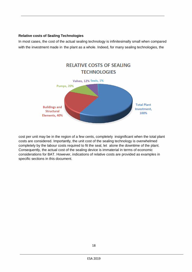
cost per unit may be in the region of a few cents, completely insignificant when the total plant
costs are considered. Importantly, the unit cost of the sealing technology is overwhelmed
completely by the labour costs required to fit the seal, let alone the downtime of the plant.
Consequently, the actual cost of the sealing device is immaterial in terms of economic
considerations for BAT. However, indications of relative costs are provided as examples in
specific sections in this document.
Relative costs of Sealing Technologies
In most cases, the cost of the actual sealing technology is infinitesimally small when compared
with the investment made in the plant as a whole. Indeed, for many sealing technologies, the
ESA 2019
19
Section 3. Static Seals (Gaskets)
Where pipe work and process equipment on an industrial installation need to be inspected, maintained and / or repaired on a regular basis, connections are usually in the form of bolted flanges for easy removal and replacement. Individual flanges generally do not have very large leaking losses, but since plants utilise so many flanges, they can make a major contribution to the overall leaking losses. For example, a major German chemicals manufacturer reported that emissions from flanges represent 28% of the total fugitive emissions from their plants.
As a general rule, where a removable connection is unnecessary, flanges should be replaced with welded piping. Where welding is not feasible, the flange joint system must be appropriate for the application and should be maintained by trained personnel only.
A brief guide to gaskets and flanged connections follows, a more detailed guide on gasket selection, installation and maintenance are available online from the European Sealing Association. (European Sealing Association (ESA) / Fluid Sealing Association of America (FSA), Gasket Handbook
GASKETS
A gasket is used to create and retain a static seal between two stationary flanges, which may connect plant equipment, and which may contain a substance under pressure. These static seals aim to provide a barrier to block any leakage. To achieve this, the gasket must be able to flow into (and fill) any irregularities in the flange surfaces being sealed, while also resist extrusion and creep under operating conditions.
The gasket is compressed by clamping forces causing it to flow into any flange imperfections. The combination of contact pressure between the gasket and flanges, and densification of the gasket material, prevents the escape of the contained media. As such, gaskets are vital to the operation of industrial equipment and therefore are an integral design element.
On seating, a gasket must be able to act against minor alignment and flange imperfections such as; non-parallel flanges, distortion troughs / grooves, surface waviness, surface marks/scratches, corrosion and other surface imperfections.
When assembled, a flange gasket seal or ‘joint’ is usually compressed by bolts under tension. In order to ensure the maintenance of the seal throughout the lifetime of the assembly, enough pressure must remain on the gasket surface to prevent leakage. Under operating conditions, this pressure will be reduced by hydrostatic end thrust, the force produced by the internal pressure which acts to open the flanges.
The gasket is also subject to a side force due to the internal fluid pressure attempting to push it out of the connection. To maintain a seal, the effective compressive pressure on the gasket (that is, the assembly load minus the hydrostatic end thrust) must be greater than the internal pressure by a multiple which is dependent on the gasket type/material, the process involved and level of tightness required. A number of publications provide more detail of the flange/gasket interaction.

ESA 2019
20
FIGURE 1- FLANGE / GASKET INTERACTION
The primary function of a gasket is to create and maintain a seal between flanges, under conditions which may vary from one joint to another. To meet these varying conditions, a number of flange / fastener / gasket systems have been
developed, and many factors must be considered when selecting the most appropriate assembly.
Table 1- Factors to be considered when using a bolted flange connection
Application Flange arrangement Gasket
Pressure of media Configuration / type Blow out resistance Temperature of media Surface finish Creep resistance Chemical reactivity of
mediaMaterial Stress relaxation
Corrosive nature Available bolt load Ability to recover / elasticity Searching ability of media Likelihood of corrosion /
erosionExpected service life
Viscosity Flange strength / stiffness Comparative cost pH of media (acidity) Alignment tolerance Chemical and physical compatibility
Concentration Ease of handling / installation / removal
Fire resistance Seal ability
Combined pressure temperature resistance
Specific Approvals
Technical Regulations
The performance of the seal depends upon the interaction of all the elements of the flange joint system.
Figure 2 - Elements of the flange joint system
Only when all the elements of the system are working together will the seal be maintained. The integrity of a safe seal depends upon; selection of components for the application, preparation, cleaning, installation and assembly, correct bolt tightening and loading and regular inspection.
The behaviour of a flanged joint in service depends on

ESA 2019
21
whether or not the force created by the fasteners will clamp the joint components together with enough force to resist failure of the seal, but small enough to avoid damage to the joint components (fasteners, gasket etc). The clamping load on the joint is created on assembly, as the nuts on the fasteners are tightened. This creates tension in the fastener (often referred to as preload).
Effectively, the entire system operates as a spring, with the fasteners being stretched and the other joint components being compressed. To reduce the bolt relaxation, it is recommended to use only one washer under the turning part (bolt head or nut).
GASKET SELECTION
Primarily, gasket selection must be based upon the sealing capability (appropriate to the application), compatibility with the media (process fluid), operating temperature and pressure, variations of operating conditions (for example, during cycling) and the type of joint involved (raised face, tongue and groove, RTJ)
Gaskets can be defined into 3 main categories:
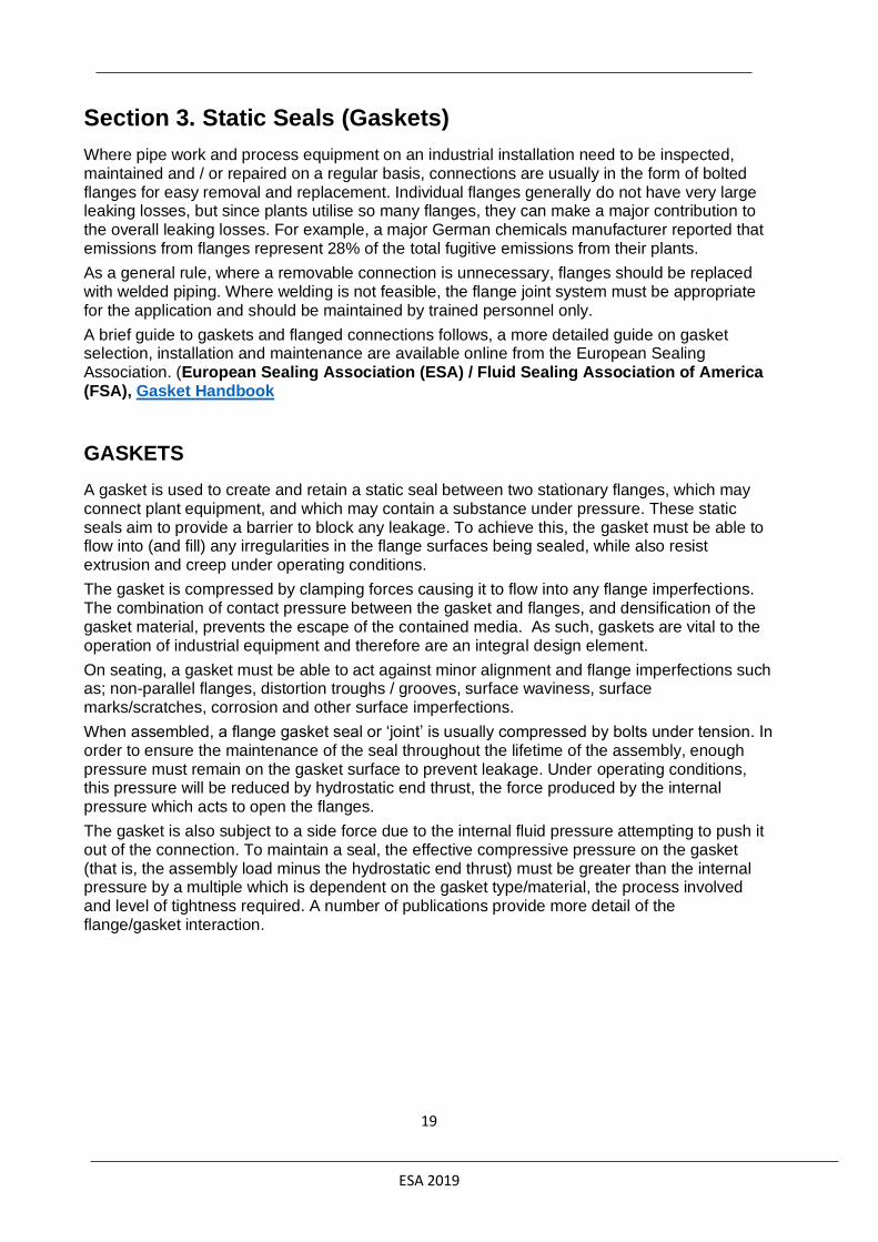
1. Soft gaskets (non-metallic): Often composite sheet materials, suitable for a wide range ofgeneral and corrosive chemical applications. Generally limited to low to medium pressureapplications. The limits of sealing materials are based on the calculation acc. to EN 1591-1
and the gasket characteristics acc. EN 13555. See paragraph below – assembly procedure– chart of EN 1591 calculation
Types include: fibre reinforced sheet, exfoliated graphite, sheet PTFE in various forms and high temperature inorganic sheet materials like Graphite and Mica.
ESA 2019
22
Fibre reinforced sheet cut gasket Graphite reinforced sheet cut gasket
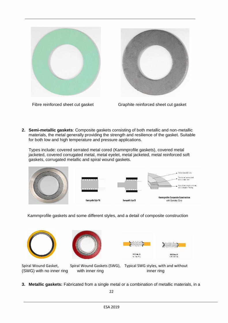
2. Semi-metallic gaskets: Composite gaskets consisting of both metallic and non-metallicmaterials, the metal generally providing the strength and resilience of the gasket. Suitablefor both low and high temperature and pressure applications.
Types include: covered serrated metal cored (Kammprofile gaskets), covered metal jacketed, covered corrugated metal, metal eyelet, metal jacketed, metal reinforced soft gaskets, corrugated metallic and spiral wound gaskets.
Kammprofile gaskets and some different styles, and a detail of composite construction
Spiral Wound Gasket, Spiral Wound Gaskets (SWG), Typical SWG styles, with and without (SWG) with no inner ring with inner ring inner ring
3. Metallic gaskets: Fabricated from a single metal or a combination of metallic materials, in a

ESA 2019
23
variety of shapes and sizes. Suitable for high temperature and pressure applications.
Types include: Lens rings, ring type joints (RTJ) and weld rings.
Ring Type Joints (RTJ), and various typical cross-sections of RTJs
The mechanical characteristics and sealing performance capabilities of these categories vary a lot. The gasket must be resistant to the media being sealed. For gaskets which are electrically conductive, consideration must also be given to electrochemical (or “galvanic”) corrosion. Gaskets cut from sheets, always use the thinnest material possible, but thick enough to compensate for unevenness of the flange surfaces, their parallelism, surface finish and rigidity etc. The thinner the gasket, the higher the bolt load which the gasket can withstand, the less the loss of bolt stress due to relaxation, and hence a longer possible service life.
For more information about mechanical characteristics of gasket types, please refer to EN13555 for specific performance details and recommendations for particular applications, please consult the gasket’s manufacturer.
STORAGE AND HANDLING OF GASKETS AND GASKET MATERIALS
Whilst it is clear that re-using gaskets is definitely NOT recommended, most gasket materials can be used safely after storage for many years, ageing will have an effect only on the performance of certain types of gasket materials. Primarily, materials bonded with elastomers, like fibre sheet which should not be used after 3-5 years from the date of manufacture. This is not a problem for metallic gaskets, but it may have an effect on semi-metallic gaskets (specifically, those which are combined with elastomer-bound materials).
All gaskets and gasket materials are best handled with care and attention. Bent, nicked, gouged, scratched or hammered gaskets will not seal!
Assembly procedures
For the seal to perform as designed, proper assembly of the joint is crucial. This process is subject to a large number of variables, including the condition of all the components, the smoothness, hardness and the lubricity of surfaces, the calibration of the tools, the accessibility of the fasteners and the
FIGURE 3 - OPERATING WINDOW USING EN1591
TERMINOLOGY (Q = INSTALLED GASKET STRESS QS= GASKET
STRESS IN SERVICE)

ESA 2019
24
environment in which the engineers must operate. Ultimately the install wants to get the joint evenly compressed and in the operating window of the joint.
EN1591 can be used to select a gasket stress, Q, in the operating window, Q maybe limited due
to leakage rate considerations or material limitations; the force to create the stress then has to
be applied via the fasteners. Despite the number of developments to improve the reproducibility
of fastening flanged joints (such as tension control fasteners, hydraulic tensioning devices,
ultrasonic fastener analysis and simultaneous torque / turn methods), torque is the most popular
method to control joint tightening and the torque wrench the tool of choice.
Torque to force calculations involve overcoming the friction of the load bearing surfaces rubbing
against each other. Unlubricated bolts can lose half the applied torque due to friction, requiring
the installer to apply twice the amount of torque for the same amount of bolt force. The amount
of force lost due to friction is calculated using the friction factor, μ this is the co-efficient between
applied and actual clamping force created by the bolt.
Methods for calculating the applied force created by a
standardised bolt under torque can be found in ASME
PCC-1-2013, however the friction factor is generally a
hard value to gauge. Lubrication manufacturers will
sometimes quote a value that can be used in
calculations, but general values can be found in Table 2.
Installation in this document will be briefly covered but th ESA/FSA Installation Booklet available online covers installation in great detail. There is also an installation leaflet for use in
the field, to act as a quick reminder for installation personnel.
Calculation: Make sure all calculations are done before installation begins, this prevents “back
of the hand” calculations being made on-site which may contain errors.
Tools: Protective clothing, cleaning brush (brass is recommended), tensioners (calibrated
torque wrenches as a minimum or another system with a controlled torque). High quality
lubricant.
Cleaning: Ensure all surfaces to be sealed are clean of dirt/grease or remains of another
gasket, clean dirt / old grease off any bolts with the brass brush or for really hard to remove
pieces use a brass chisel. Take care to not damage the sealing surfaces.
Visual: Check for any serious defects, flange warping etc. Check components are OK and
correct for application. Take particular care to check the bolt threads for damage.
Lubrication: All load bearing surfaces which are not sealing surfaces should be lubricated, bolt
threads and heads, nut threads and heads, washer surfaces and flange contact areas. A higher
Lubrication Friction factor, μ
Unlubricated 0.40-0.60
Normal lubricant 0.15-0.25
Quality lubricant 0.10-0.15
Table 2 - Generic bolt friction factors

ESA 2019
25
quality lubricant will not only make the joint easier to open at service end, but also lowers the
amount of torque force lost due to friction when torqueing up the fasteners.
Installation: The gasket should be placed centrally as possible and the flange surfaces should
meet up well. The fasteners should be easily loosely installed and well lined up with appropriate
holes. For large diameter gaskets multiple personnel may be required to ensure the gasket
doesn’t bend or warp during handling into place.
Tightening: The sequence in which bolts or studs are tightened affects the distribution of the
gasket stress. Improper bolting may move the flange out of parallel. A gasket will usually be
able to compensate for a small amount of distortion of this type, but serious difficulties will be
encountered if the flanges are substantially out of parallel so always torque nuts in a cross bolt
tightening pattern, see Table 4 below. It is also required that the force is applied stages to
ensure equal compression around the gasket. The ESA/FSA recommend a 4 pass system
where initially the bolts are tightened by hand, then 33% of the required torque, 66%, 100% and
a final pass at 100% a minimum of 4hrs after the first 100% pass.
Database: The flange should be tagged with a unique identification so its history can be
tracked. You should record the gasket, bolt nut, washer, lubricant information alongside torques
used and the dates.
Retightening: For the majority of materials in the flange system, relaxation sets in after
a fairly short time. For soft gasket materials, one of the major factors is usually the creep
relaxation of the gasket. Relaxation causes a loss of load on the gasket, increasing the
possibility of a leak. Many engineers recommend that fasteners should be re-tightened to the
original torque 24 hours after the initial assembly. Any re-torqueing is strictly done at ambient
temperature, however any elastomer based materials subjected to heat should never be re-
torqued.
-
Figure 4 - Bolt tightening patterns
EXPECTED EMISSIONS
EN1591 calculations are designed so that the engineer calculating the joints bolt loading can select a target leakage rate. Gasket manufacturers generally use a leakage rate value of L0.01 mg/m/s aka. Mg/ (m*s) as a minimum required gas leakage rate. (VDI2200 TA Luft 2017 requirement) generally tested with helium, the escaped mass (mg) per second is normalized per meter of the seal length exposed to the pressurised media i.e. the internal circumference of a ring gasket. Therefor to calculate an expected emissions rate in mg/s the targeted leakage rate

ESA 2019
26
is multiplied by the total seal length in m. This can be used then on multiple joints of differing sizes.
SAFETY ASPECTS AND JOINT FAILURE
Joints fail, not just gaskets! Seal failure can occur when any component of the flange / fastener / gasket system is not performing correctly. The normal result is leakage from the joint, which may be virtually undetectable at first and build up over time, or may be a sudden, drastic failure. It is mainly observed when the fasteners fail to perform their clamping function, usually when they provide too little force, but occasionally when they exert too much!
A study commissioned by the Pressure Vessel Research Council (PVRC) of the USA, indicated that most flange joint failures resulting in leaks are due to improper installation (26%), flange damage (25%), gasket (22%), loose bolts (15%) and flange misalignment (12%). This list is not complete and further details are available in a number of publications 5.
Some common failures and there reasons are;
Fasteners under-tightened; incorrect initial torque, damaged fastener, self-loosening (vibrations), no lubricant used.
Fasteners over-tightened; gasket crushed, flanges bent.
Fasteners yielded; bolts don’t meet design, bolts threads sheared, bolts stretched past elastic limit.
Fastener fault; double threaded, cracked or nicked threads, no washers used.
Gasket faults; wrong material for media, wrong thickness for conformability, external forces (bending moments), over heated, gasket reused, gasket greased up, retightened at temperature, embrittlement.
Flange faults; excessive surface damage or warping, not parallel, wrong material, not cleaned beforehand.
User faults; incorrect torque calculations, poor maintenance, installer(s) not trained, incorrect tools, cheap materials, poor handling
MINIMIZING THE CHANCES OF JOINT FAILURE
The selection of the correct materials for the application is fundamental. Make sure that all components of the joint are compatible with each other and with the conditions during service. Follow the gasket storage and handling recommendations as given by the manufacturer. Follow the cleaning and visual inspection recommendations, to ensure that the joint components are free from defects and fit for use. Good installation practices are essential, the use of fully trained personnel and calibrated tools ensure the joint is put together with sufficient care; else it cannot be expected to provide a safe seal.
Corrosion is one of the most common challenges in the field! It can affect the integrity of the clamping force and will reduce the life of the joint components.
Stress corrosion cracking (SCC) is the result of a combination of stress and electrochemical attack. All metallic fasteners are susceptible to SCC under certain conditions, but most of the problem can be minimised with suitable heat treatment. As with corrosion, provision of a suitable coating (aluminium, ceramics, or graphite) on the fasteners can minimise contact with the electrolyte. However, stress control is the most common way to reduce SCC, by keeping the stress level in the fasteners below a given limit (specific for the material).

ESA 2019
27
Fatigue is time dependent and in general, the higher the loads, the faster fatigue will set in. The item which usually has the greatest impact on reducing fatigue of the joint is the reduction of load excursions. Therefore, identify and achieve the correct preload in the fasteners. Note the differences in maximum preload between fasteners with rolled versus machined threads. Also, periodically replace the fasteners before they fail. Ideally, replace the fasteners when reassembling the joint!
Self-loosening is usually experienced in the presence of vibration. This is often countered by preventing slip between the fastener, nut and / or joint components by mechanical lock nuts or washers, or by the use of adhesives.
Figure 5 - Simplified Installation Instructions
ESA 2019
SECTION 4. Mechanical Seals
DYNAMIC SEALING
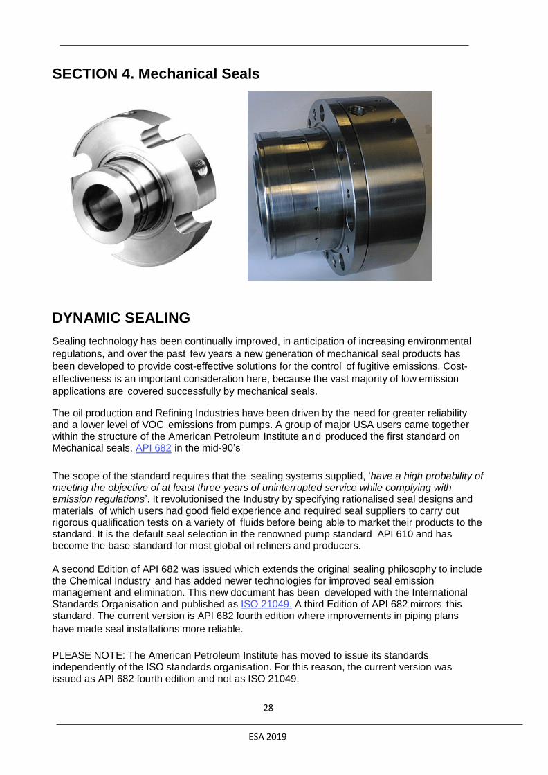
Sealing technology has been continually improved, in anticipation of increasing environmental
regulations, and over the past few years a new generation of mechanical seal products has
been developed to provide cost-effective solutions for the control of fugitive emissions. Cost-
effectiveness is an important consideration here, because the vast majority of low emission
applications are covered successfully by mechanical seals. The oil production and Refining Industries have been driven by the need for greater reliability and a lower level of VOC emissions from pumps. A group of major USA users came together within the structure of the American Petroleum Institute a n d produced the first standard on Mechanical seals, API 682 in the mid-90’s
The scope of the standard requires that the sealing systems supplied, ‘have a high probability of meeting the objective of at least three years of uninterrupted service while complying with emission regulations’. It revolutionised the Industry by specifying rationalised seal designs and materials of which users had good field experience and required seal suppliers to carry out rigorous qualification tests on a variety of fluids before being able to market their products to the standard. It is the default seal selection in the renowned pump standard API 610 and has become the base standard for most global oil refiners and producers.
A second Edition of API 682 was issued which extends the original sealing philosophy to include the Chemical Industry and has added newer technologies for improved seal emission management and elimination. This new document has been developed with the International Standards Organisation and published as ISO 21049. A third Edition of API 682 mirrors this standard. The current version is API 682 fourth edition where improvements in piping plans
have made seal installations more reliable.
PLEASE NOTE: The American Petroleum Institute has moved to issue its standards independently of the ISO standards organisation. For this reason, the current version was issued as API 682 fourth edition and not as ISO 21049.
28
ESA 2019
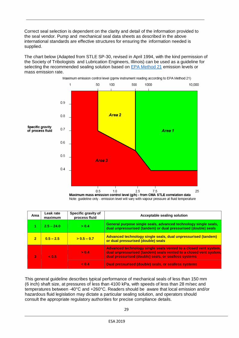
Correct seal selection is dependent on the clarity and detail of the information provided to the seal vendor. Pump and mechanical seal data sheets as described in the above international standards are effective structures for ensuring the information needed is supplied. The chart below (Adapted from STLE SP-30, revised in April 1994, with the kind permission of the Society of Tribologists and Lubrication Engineers, Illinois) can be used as a guideline for selecting the recommended sealing solution based on EPA Method 21 emission levels or mass emission rate.
Area Leak rate
maximum
(g/h)
Specific gravity of
process fluid Acceptable sealing solution
1 2.5 – 24.0 > 0.4 General purpose single seals, advanced technology single seals, dual unpressurised (tandem) or dual pressurised (double) seals
2 0.5 – 2.5 > 0.5 – 0.7 Advanced technology single seals, dual unpressurised (tandem) or dual pressurised (double) seals
3 < 0.5
> 0.4 Advanced technology single seals vented to a closed vent system, dual unpressurised (tandem) seals vented to a closed vent system, dual pressurised (double) seals, or sealless systems
< 0.4 Dual pressurised (double) seals, or sealless systems
This general guideline describes typical performance of mechanical seals of less than 150 mm (6 inch) shaft size, at pressures of less than 4100 kPa, with speeds of less than 28 m/sec and temperatures between -40°C and +260°C. Readers should be aware that local emission and/or hazardous fluid legislation may dictate a particular sealing solution, and operators should consult the appropriate regulatory authorities for precise compliance details.
29

ESA 2019
When initially introduced by STLE, the above 'Application Guide' was derived from user experience in the field, incorporating the performance of mechanical seals from a wide variety of suppliers. The guide represents a reliable performance profile for mechanical seals from all manufacturers, each of whom has access to differing levels of technological sophistication. Clearly, those manufacturers with access to more advanced technology are able to provide products with generally higher performance levels.
Many of today's single mechanical seals, using modern materials and advanced technology, are reliably performing within Area 2 of the Application Chart, with emissions typically below 1 g/h under normal operating conditions in the field. For this reason, where low emission rates are essential, operators should approach mechanical seal manufacturers in order to be assured of the use of modern materials and advanced technology. Mechanical seal manufacturers should be able to demonstrate how today's mechanical seals incorporate 'design-in' capabilities to offset the combined effects of pressure distortion, thermal distortion and heat generation.
Advanced technology single seals The simplest form of mechanical seal, still employed widely today, is a single mechanical seal installation aimed at general purpose applications and consists of a fixed ring in the casing held in tight contact with a rotating ring on the shaft to form a seal. More recently, the application of advanced sealing technology has enabled the development of reliable, low emission single mechanical seals, which can give leak rates close to those of some dual seal installations. The technologies employed include highly sophisticated finite element and other modelling techniques in the optimisation of component shapes, computational fluid dynamics, specialised material developments, improved tribological properties rubbing face surface profile adjustments and pre-set packaged assemblies to eliminate fitting errors. A further essential factor, in support of the enhanced performance and reliability of new seal technologies, is the performance testing capability of the reputable seal manufacturers.
Additionally, for applications where hazard containment is required from the single seal arrangement, it is usual to include some form of external containment device to allow collection of any abnormal levels of vapour leakage and, where required, warn operators through a pressure induced alarm system. There are many kinds of secondary containment devices, including fixed or floating bushing and lip seals (spring energised or pressure energised). The space between the mechanical seal and some types of secondary containment device can be filled with a fluid to provide an environment where degradation or crystallisation of leakage is prevented.
30

ESA 2019
A single mechanical seal provides the most economical form of seal, with emission values typically below 1 g/h under normal operating conditions in the field. Single mechanical seals provide cost effective, reliable sealing for most VOC services, in line with API Standard 682 specifications provided the following conditions are satisfied:
o process fluid specific gravity > 0.4
o vapour pressure margin in the seal chamber is sufficient for seal
face lubrication process or flush fluid provides adequate
lubrication and cooling of the seal faces
For advanced technology single mechanical seals, users report leak rates of between 0.42 and 1.25 g/h on one petrochemical plant in the Netherlands and between 0.63 and 1.67 g/h on a chemical plant in Germany.
This experience and data has been consolidated into the German Technical Rule VDI 2440 -‘Emission Control – Mineral Oil Refineries’ which recommends that operators use 1 g/h as the mean leakage rate from single mechanical seals on process pumps.
Single seals with a mechanical containment seal (dual unpressurised seals)
The simple sophistication of a single seal (which contains the process fluid) is attractive to operators but where the process fluid is a VOC and the emissive leakage to the atmosphere requires minimising it is common to include a second mechanical seal outboard of this primary seal. This provides a far more effective containment device than bushings.
The VOC leakage entering the containment chamber between the two seals can then be effectively channeled to a plant flare or vapour recovery system. Dual Unpressurised seal arrangements will provide very low levels of process emissions to the atmosphere.
Dual unpressurised seals use two different technologies for the lubrication of the outer mechanical containment seal. The numerically highest proportion fills the containment chamber with a separate buffer liquid that is piped to and from an adjacent reservoir. Flow is induced around the circuit, both lubricating the containment seal and assisting the channeling of VOC leakage into the buffer-fluid reservoir, where it is able to separate from the carrier buffer liquid. Ordinarily there is a connection from the top of the reservoir to a plant flare or vapour recovery system together with an orifice and an alarm to warn of deterioration in the sealing performance of the primary seal. This is referred to as flush Plan 52 in ISO 21049.
Dual seal arrangements with unpressurised buffer liquid provide emission values typically below 0.01 g/h, achieving emission levels less than 10 ppm (< 1 g/day).
Engineers on a hydrocarbon plant in the USA report emissions of less than 10 ppm (< 1 g/day) from most dual unpressurised seals with buffer liquids on site after 12 months operation from start-up. The alternative and more recent technology has been created by advances in high speed gas lubrication of mechanical seals; no liquid buffer is required and the VOC gas, now at atmospheric conditions in the containment chamber, itself provides the lubrication of the containment seal. The containment chamber is directly connected to a plant flare or vapour recovery system with an orifice and a pressure alarm to warn of deterioration in the sealing performance of the primary seal.
31

ESA 2019
The benefit to the operator is a lower investment and operating cost. This is referred to as flush Plan 76 in API 682 and ISO 21049.
A recent assembly of data from European and USA plants studying single seals with gas
lubricated mechanical containment seals concluded that 93.8% had Method 21 emission
levels less than 1000 ppm and over 70% less than 50 ppm.
To achieve near complete elimination of emission to the atmosphere some plant operators
connect a flow of Nitrogen buffer gas to purge the gas lubricated, mechanical containment
seal of process VOC’s and help channel them to the recovery/disposal system. This is
referred to as Flush Plan 72 in API 682 and ISO 21049.
Double seals with a separate barrier system (dual pressurised seals)
This solution consists of two seals with a barrier fluid (liquid or gas) between them operated
at a pressure greater than the process stream. Any leakage (outboard to atmosphere or
inboard to the process stream) is of the barrier fluid, and therefore, selection of a safe barrier
fluid compatible with the process stream is essential. This type of seal arrangement is useful
for sealing process fluids with poor lubricating properties, on services where single seals are
unreliable, or where the process fluids may change frequently (such as in pipeline services)
and is selected when the process fluid is particularly hazardous.
Dual pressurised systems virtually eliminate leakage of the process fluid into the environment
and typically have emission values approaching zero, usually described as 'not measurable
with existing instrument technology'. Liquid lubricated mechanical seals typically use
water or a light lubricating oil as the barrier fluid supplied from a self-contained support
system and gas lubricated designs utilise a convenient plant gas source such as Nitrogen
managed by a control system. This former is referred to as flush Plan 53 or 54 and the latter
flush Plan 74 in API 682 and ISO 21049.The simplicity and very low energy consumption of
dual pressurised gas seals has been a strong driver in the growth of this technology in recent
years.
32
ESA 2019
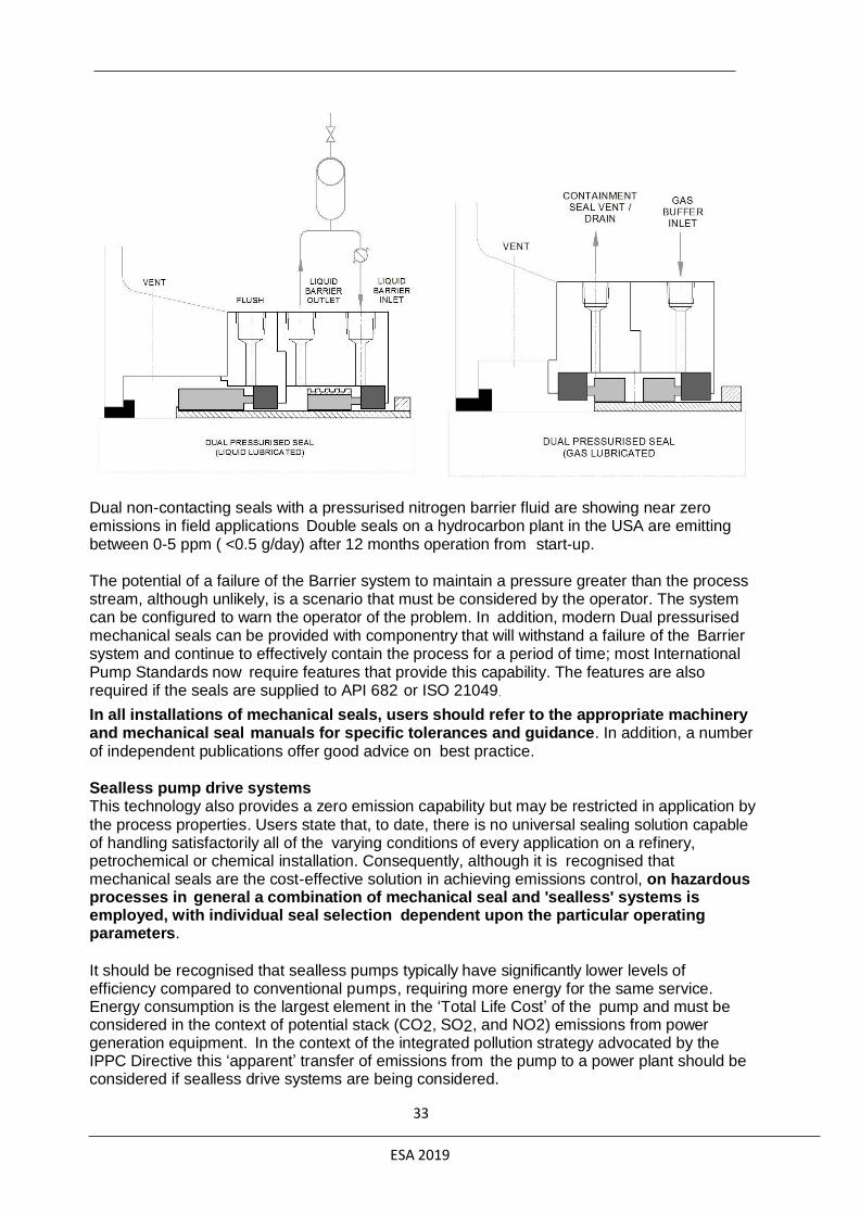
Dual non-contacting seals with a pressurised nitrogen barrier fluid are showing near zero emissions in field applications Double seals on a hydrocarbon plant in the USA are emitting between 0-5 ppm ( <0.5 g/day) after 12 months operation from start-up. The potential of a failure of the Barrier system to maintain a pressure greater than the process stream, although unlikely, is a scenario that must be considered by the operator. The system can be configured to warn the operator of the problem. In addition, modern Dual pressurised mechanical seals can be provided with componentry that will withstand a failure of the Barrier system and continue to effectively contain the process for a period of time; most International Pump Standards now require features that provide this capability. The features are also required if the seals are supplied to API 682 or ISO 21049.
In all installations of mechanical seals, users should refer to the appropriate machinery and mechanical seal manuals for specific tolerances and guidance. In addition, a number of independent publications offer good advice on best practice.
Sealless pump drive systems This technology also provides a zero emission capability but may be restricted in application by the process properties. Users state that, to date, there is no universal sealing solution capable of handling satisfactorily all of the varying conditions of every application on a refinery, petrochemical or chemical installation. Consequently, although it is recognised that mechanical seals are the cost-effective solution in achieving emissions control, on hazardous processes in general a combination of mechanical seal and 'sealless' systems is employed, with individual seal selection dependent upon the particular operating parameters.
It should be recognised that sealless pumps typically have significantly lower levels of efficiency compared to conventional pumps, requiring more energy for the same service. Energy consumption is the largest element in the ‘Total Life Cost’ of the pump and must be considered in the context of potential stack (CO2, SO2, and NO2) emissions from power generation equipment. In the context of the integrated pollution strategy advocated by the IPPC Directive this ‘apparent’ transfer of emissions from the pump to a power plant should be considered if sealless drive systems are being considered.
33
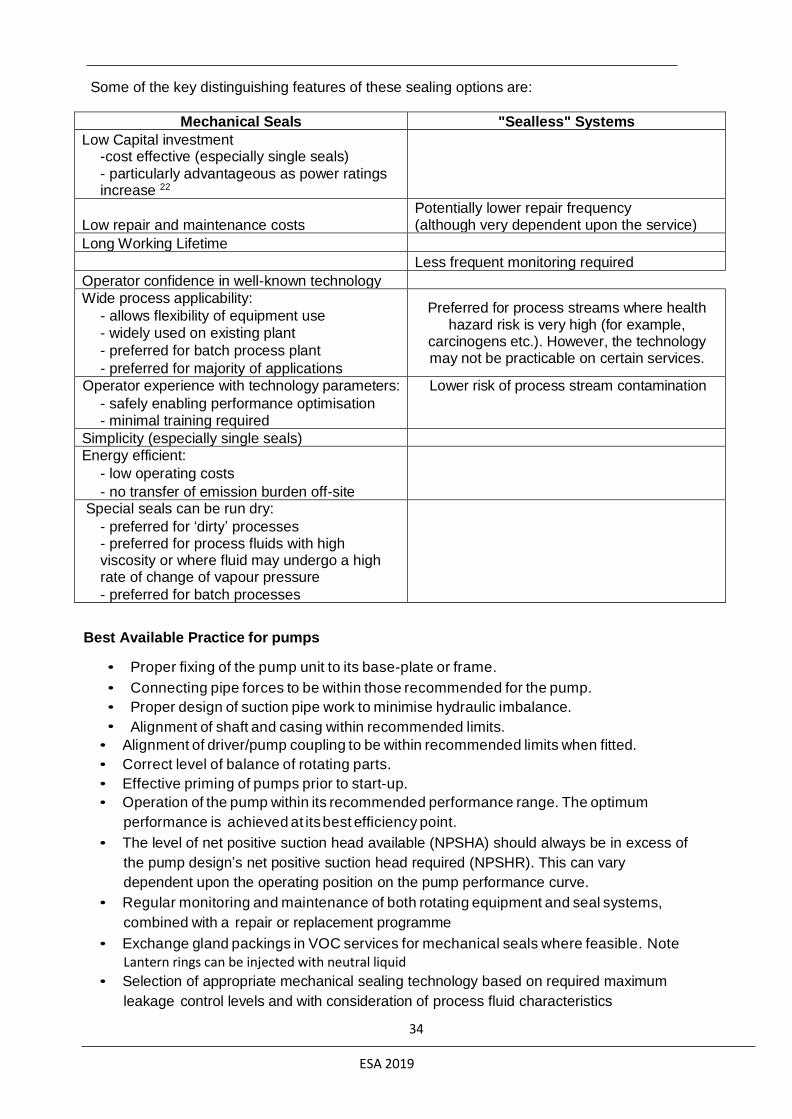
ESA 2019
Some of the key distinguishing features of these sealing options are:
Mechanical Seals "Sealless" Systems
Low Capital investment -cost effective (especially single seals)
- particularly advantageous as power ratings increase 22
Low repair and maintenance costs
Potentially lower repair frequency (although very dependent upon the service)
Long Working Lifetime
Less frequent monitoring required
Operator confidence in well-known technology
Wide process applicability:
- allows flexibility of equipment use
- widely used on existing plant
- preferred for batch process plant
- preferred for majority of applications
Preferred for process streams where health hazard risk is very high (for example,
carcinogens etc.). However, the technology may not be practicable on certain services.
Operator experience with technology parameters:
- safely enabling performance optimisation - minimal training required
Lower risk of process stream contamination
Simplicity (especially single seals) Energy efficient:
- low operating costs
- no transfer of emission burden off-site
Special seals can be run dry:
- preferred for ‘dirty’ processes - preferred for process fluids with high viscosity or where fluid may undergo a high rate of change of vapour pressure
- preferred for batch processes
Best Available Practice for pumps
• Proper fixing of the pump unit to its base-plate or frame.
• Connecting pipe forces to be within those recommended for the pump.
• Proper design of suction pipe work to minimise hydraulic imbalance.
• Alignment of shaft and casing within recommended limits.
• Alignment of driver/pump coupling to be within recommended limits when fitted.
• Correct level of balance of rotating parts.
• Effective priming of pumps prior to start-up.
• Operation of the pump within its recommended performance range. The optimum
performance is achieved at its best efficiency point.
• The level of net positive suction head available (NPSHA) should always be in excess of
the pump design’s net positive suction head required (NPSHR). This can vary
dependent upon the operating position on the pump performance curve.
• Regular monitoring and maintenance of both rotating equipment and seal systems,
combined with a repair or replacement programme
• Exchange gland packings in VOC services for mechanical seals where feasible. Note
Lantern rings can be injected with neutral liquid
• Selection of appropriate mechanical sealing technology based on required maximum
leakage control levels and with consideration of process fluid characteristics
34
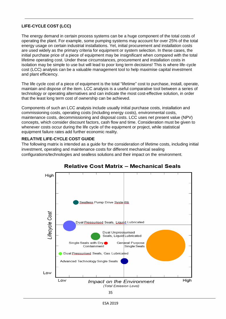
ESA 2019
LIFE-CYCLE COST (LCC)
The energy demand in certain process systems can be a huge component of the total costs of operating the plant. For example, some pumping systems may account for over 25% of the total energy usage on certain industrial installations. Yet, initial procurement and installation costs are used widely as the primary criteria for equipment or system selection. In these cases, the initial purchase price of a piece of equipment may be insignificant when compared with the total lifetime operating cost. Under these circumstances, procurement and installation costs in isolation may be simple to use but will lead to poor long term decisions! This is where life -cycle cost (LCC) analysis can be a valuable management tool to help maximise capital investment and plant efficiency.
The life cycle cost of a piece of equipment is the total “lifetime” cost to purchase, install, operate, maintain and dispose of the item. LCC analysis is a useful comparative tool between a series of technology or operating alternatives and can indicate the most cost-effective solution, in order that the least long term cost of ownership can be achieved.
Components of such an LCC analysis include usually initial purchase costs, installation and commissioning costs, operating costs (including energy costs), environmental costs, maintenance costs, decommissioning and disposal costs. LCC uses net present value (NPV) concepts, which consider discount factors, cash flow and time. Consideration must be given to whenever costs occur during the life cycle of the equipment or project, while statistical equipment failure rates add further economic reality.
RELATIVE LIFE-CYCLE COST GUIDE
The following matrix is intended as a guide for the consideration of lifetime costs, including initial
investment, operating and maintenance costs for different mechanical sealing
configurations/technologies and sealless solutions and their impact on the environment.
35
ESA 2019
The matrix is intended to be used with typical rotodynamic pumps but cannot be assumed to be
universally applicable. The bubble size reflects population of seal type (hence, general purpose
single seals are by far the majority of the installed pump population, whereas gas lubricated
dual pressurised seals, being a more recent technology development, are the smallest).
Although often overlooked, the energy efficiency of the particular sealing technology can make
the most significant contribution to the life cycle cost (LCC) overall. In addition reduced energy
efficiency contributes to more emissions at the power generation plant, hence more impact on
the environment in considering total emission level.
The general rationale behind the matrix guide is as follows;
General Purpose Single Seals:
Rotary seals, predominantly unbalanced. Initial Investment is smallest of all sealing
technologies considered, but higher energy usage and shorter MTBF increase the LLC.
Emission range typically 500 -1000 ppm (applying EPA Method 21).
Advanced Technology Single Seals:
Balanced stationary seals with advanced face designs. Initial investment higher than General
Purpose Single Seals but with a potential for extended MTBF and therefore lower LCC.
Emissions ranges 100 - 500 ppm.
Dual Seals, unpressurised:
Different containment technologies may be used, but MTBF values should be equivalent to
Advanced Technology single seals. Investment costs are somewhat lower then pressurised
dual seals and therefore have a lower LLC. Emission range 50 – 500 ppm depending
on the containment technology applied.
Dual Seals, pressurised, liquid barrier:
Normally higher capital investment and running costs than dual unpressurised seals.
Emissions approaching zero ppm.
Dual Seals, pressurized, gas barrier:
Lower capital and operational costs than liquid barrier technologies. Emissions
levels comparable to sealless pump technologies at lower investment and
maintenance costs.
Sealless pump technologies:
The chart position is based primarily on magnetic drive pumps. This outlined MTBF's for
seals and sealless pumps as being on average comparable. Repair costs of sealless
pumps are typically higher than dual mechanical seals.
36

ESA 2019
A detailed and separate examination of the initial investment and operating cost, comparing
the differing mechanical sealing technologies, is shown in the table below:
Relative Costs for Different Mechanical Sealing Technologies
Emission Level1 1000 500 50 10 0 0
Initial Investment 100% 125% 250% 500% 500% 435%
Operating Cost 100% 65% 100% 120% 190% 100%
Total Life Cycle Cost2
100%
80%
135%
205%
260%
170%
Notes:
1- ppm level measured using EPA Method 21 2 - Based on a discounted 10 year operating life 3 - Includes reservoir 4 - Includes gas seal panel
The information in the table above has been generated using the Seal Life-Cycle Cost Estimator
tool, which has been developed by the ESA and FSA Mechanical Seals Divisions
This tool allows you to estimate life-cycle costs for different sealing solutions on a
comparative basis to assist in decision-making when specifying capital projects or upgrading
existing rotating equipment technology. The Seal Life-Cycle Cost Estimator allows
comparison of a variety of sealing arrangements including single seals, dual seals, single
seals with liquid lubricated and gas lubricated secondary containment, non-contacting gas
seals, compression packing.
Life Cycle Costs are influenced strongly by the reliability of the selected sealing solution. Thermal management of the seal environment can lead to extensive losses. On some high temperature applications this can lead to power consumption of the sealing system exceeding that of the pump driver.
Users are advised to think carefully about the individual MTBR (Mean Time Between Repair)
values which are most appropriate for the different sealing solutions considered and, if
necessary, contact your mechanical seal, packing, or pump supplier for guidance.
Compressors
EMISSION MANAGEMENT IN COMPRESSORS
The sealing of two types of rotodynamic compressor will be discussed in this Section. The first
grouping is lower velocity, pos it ive displacement designs, operating typically at 50/60 cycle
synchronous speeds. They are used with many different types of gases but are commonly used
in smaller refrigeration cycle services. The same technology is applied on some process gases.
The shaft bearing assemblies are at either end of the shaft and mounted in-board of the seal
assembly. Equipment leakage losses occur mainly where the rotating shaft penetrates the
casing. The technologies employed are similar to pumps;
37

ESA 2019
Single Mechanical Seals with an energised containment seal
Single Mechanical Seals with a mechanical containment seal and leakage collection (dual
unpressurised seals) Double Seals with a separate barrier fluid (dual pressurised seals)
Centrifugal Process Compressors are commonly applied on VOC process gases but typically
operate at much higher velocities to achieve their performance efficiencies. The shaft bearing
assemblies are at either end of the shaft and mounted out-board of the seal assembly.
Equipment leakage losses occur mainly where the rotating shaft penetrates the casing at its
Drive and non-drive ends. The technologies employed are;
• Labyrinth Seals
• Single Mechanical Seals
• Single Mechanical Seals with a mechanical containment seal and leakage collection (dual
unpressurised seals) Tandem Mechanical Seals with a mechanical containment seal and
leakage collection (Triple seals)
• Double Seals with a separate barrier fluid (dual pressurised seals) Best Available Practice for compressors
Equipment reliability is equally important in minimising emissions from compressors and the techniques which are recommended for pumps (see above) are similarly applicable. Lower velocity Rotodynamic positive displacement compressors are typically sealed by single mechanical seals lubricated by oil which jointly flows through the inboard bearing assembly. The oil is separated and recycled. To minimise process gas leakage when the equipment is static and the barrier oil has drained back to the supply reservoir, an energised lip seal or inboard mechanical seal and by-pass gallery can be employed as a damming assembly, retaining the barrier oil locally around the mechanical seal face.
To avoid the potential oil/process chemical degradation of dynamic elastomeric components used in some types of mechanical seal there is a preference for designs which utilise a metal bellows to manage its axial and alignment flexibility requirements.
It is common practice to use an energised lip seal outboard of the primary seal to contain any oil leakage. This helps channel process contaminated oil into a suitable collection chamber. This concept is improved by the addition of a gas lubricated mechanical containment seal in the same configuration as described earlier. A nitrogen buffer gas is occasionally used with this arrangement to purge the outer containment seal and assist the collection and separation of lubricating oil and process gas.
A double seal with a separate barrier fluid, is required where no emissive process leakage is permitted.
Some centrifugal compressors with an integrated gearbox are successfully sealed using similar technologies to the positive displacement type machines. These machines have relatively low velocities at the seal faces because the sealing point is at the input shaft to the gearbox. Centrifugal compressors are traditionally sealed by labyrinth seals (fixed or floating carbon bushings) or oil lubricated mechanical seals as described above for positive displacement compressors. High leakage levels from labyrinth seals however negate their use in VOC emissive services and they should be exchanged for mechanical seal assemblies.
The high capital investment and relatively poor reliability of oil lubricated mechanical seals at the high velocities employed in centrifugal compressors encouraged the development of gas lubricated mechanical seals in the 1970’s. The technology utilises macro-topographical alteration of the rubbing surface profile to encourage hydrodynamic and hydrostatic gas film
38

ESA 2019
forces; this enables the maintenance of a dynamic, non-contact gap a few microns thick. In most circumstances a single mechanical seal is employed to seal the process pressure and an outer containment seal, using the same technology, minimises the emissions to the atmosphere and channels the primary seal process leakage to a flare or recovery system. It is important for the reliability of the outer containment seal to exclude from it lubricating oil from the outer shaft bearing and, where practical, a gas purge (air or nitrogen) between two labyrinths or floating bushings is used to separate the mechanical seal assembly from the bearing. This purge assists with channeling process leakage through the containment seal into a flare or recovery system and minimising escape to the atmosphere.
In circumstances where the process gas is contaminated by a toxic impurity (e.g. H2S in a sour
hydrocarbon gas), an inert buffer gas such as nitrogen, if practical, can be used to purge the process side of the containment seal Where this is not practical, inert gas flush can be added.
In very high process pressure services the dual configuration is also employed utilising metal
spring energized polymer rings as secondary sealing elements. Such seals have been
operating at over 30000 kPa since 2001.
Other rotodynamic equipment
Other rotodynamic equipment includes agitators, reactors, de-waxing filters, dryers, mixers, rotary kiln furnaces and rotary pumps for drinking water distribution, where heavy wear and shaft misalignment are notorious. Whilst leaking valves are rightly considered to be the largest total source of fugitive emissions, large rotary vessels will generally suffer greater mass losses as a single point source. The emissions from one rotary vessel can often exceed the total emissions from a large number of valves, costing the operator a significant amount in lost product and wasted energy.
As expected, emission performance in these applications relies upon the sealing of the rotating shaft or cylinder against the stationary sections of the equipment. Yet, in many cases, accurate alignment of the rotating shaft may be difficult to achieve, particularly as differential thermal expansion and contraction takes place during the process cycle. In addition to thermal effects,
both shaft and bearings can become worn, even though speed of rotation is often low, and the net result is that the shaft can move radially by amounts in excess of 2mm, particularly on start- up. Operating equipment under these conditions may cause excessive emissions during operation and result in excessive leakages caused by premature failure and/or rapid degradation of the sealing system. It is evident that such operation should be avoided if possible by adequate equipment (re-) design and operation within the design specification.
Mechanical seals are used widely as sealing technology for agitators and mixing equipment, providing maximum control of fugitive losses in critical applications. Both single and double mechanical seals are available which are designed specifically to handle larger radial and angular misalignments (‘mixer seals’) or mechanical seals with integrated bearings which effectively constrain radial run-out directly at the point of sealing.
In other instances however, especially on existing equipment, the investment required for more sophisticated sealing technologies cannot be justified. In these cases, compression packings may provide an economical alternative. Such a sealing system often comprises a sealing flange fixed to the rotating shaft, over which sealing carriers are clamped. According to requirement, these are fitted with two or four packing rings. The appropriate contact pressure for the packing rings is achieved by means of adjustable springs or hydraulic guidance.
Rotation of the sealing carriers is prevented by suitable torque brackets. As size increases, the entire sealing system (except for the sealing flange) may be freely suspended, so that that the system can accommodate small misalignments while retaining its sealing performance. In all of these cases, the compression packings must be selected carefully to accommodate shaft
39

ESA 2019
misalignment (transient and permanent), vibration and shock loadings. Readers should consult reputable sealing material manufacturers for advice on the best choice for their specific application. BAT in other rotodynamic equipment.
Losses from large rotating machines may be reduced dramatically by a combination of
approaches:
• use mechanical seals designed to accommodate large radial and angular misalignments
(“mixer seals”)
• use mechanical seals with bearing(s) integrated into their assembly, to constrain
equipment run-out
• use advanced compression packing designs from reputable manufacturers only
• re-engineer the gland arrangement where necessary to accommodate shaft
misalignment, run-out and equipment wear
• use “live loading” (see below)
• close collaboration between the user and seal manufacturer can provide the most
economical sealing solution
In many agitators and mixing equipment, the sealing arrangement operates in either a dry environment or in media which provide little or no lubrication to the seal faces. Therefore, the applicability of single mechanical seals is limited to very slow rotating equipment where the dry run limit of the mating faces is not exceeded, and applications where an external lubricating system can be employed (such as a liquid flush, greasing system or a quench arrangement). In cases where such alternatives are neither feasible nor allowed, double pressurised seals should be considered. In critical equipment where the lowest possible emission levels need to be warranted, only double, pressurised mechanical seals provide emissions levels approaching zero.
Whilst “live-loading” is generally considered to reduce the total requirement for maintenance and adjustment, it also serves to provide cushioning for the effects of growth and contraction during thermal cycling. This is where live-loading has far greater benefit than simply for taking up wear of the packing. It also ensures that the correct initial gland load was applied by compressing the spring stacks evenly by a known amount. Inevitably, as the packing wears and the springs open-up, then their applied force decreases and eventually some re-tightening will be required.
It is evident that the variety of equipment, operating conditions and allowable emission levels require a close collaboration between the user and seal manufacturer to determine the best sealing arrangement a given application.
Emerging techniques
Split seal technology is used increasingly on large rotodynamic equipment as an alternative sealing solution for compression packings. Although split seal seals should not be installed on equipment where emissions control is critical, advances in split seal technology provide emission containment levels exceeding those of conventional packings The higher investment required for such technology is often offset by more favorable sealing efficiency, for instance when equipment maintains a vacuum. In other instances, the application of split seal technology may offer longer MTBR and lower overall operating costs.
The sealing of high vapour pressure liquids, including cryogenic liquid gases, can be sealed reliably and with lower levels of leakage using shaped, recessed regions between the seal running faces. This new technology has enabled much improved sealing Mean Time Between Failures (MTBF) of liquefied gases with corresponding lower overall emission volumes.
40

ESA 2019
RECIPROCATING SHAFTS Process equipment with reciprocating shafts is usually equipped with gland packings to
minimise emissions into the atmosphere.
Best Available Practice for reciprocating compressors
Reciprocating compressors are mainly applied in the process industry for gas transportation,
and pressure increase of various gases.
Packing Cases
Packing cases create the seal between piston rod and cylinder. The cross-head guided piston
rod is sealed towards the cylinder with a packing case design. The packing cases cover a broad
range of operating conditions and are used widely in lubricated and oil free compressors. They
consist of a series of angular plates with cup-like recesses which house the sealing elements.
These angular cups and a mounting flange are combined by tie rods. The number of sealing
elements in a packing case is determined by the operating conditions of the compressor.
In order to obtain enhanced running time, the use of cooled packing cases is often applied for
oil-free as well as lubricated compressors, depending on operating temperatures. Cooled
packing cases have internal passages for circulating coolant for heat dissipation. The coolant
channel design enables cleaning during packing case reconditioning. The closed coolant
passage meets API standards.
The packing case designs are tailored to cope with the full spectrum of pressure, temperature,
venting, purging and lubrication requirements. Customised solutions for fugitive emissions
reduction are offered from reputable manufacturers.
Packing Rings
The sealing rings are mostly segmental rings or multiple ring assemblies. Materials are either
compounds or metal for lubricated service or combinations of both.
Segmental Packing Rings
The full floating segmental ring seal fully compensates for normal wear on the rings throughout
their lifetime. Radial or tangential cut ring segments balance the wear at the contact face.
Multiple Packing rings
These are free floating packing rings, which follow the radial piston rod movement to assure a
positive seal in the packing cups. As this ring configuration has a smaller cross section, they
are suitable for restricted packing case dimensions.
Piston Rings
The clearance between the piston and the cylinder liner is sealed with piston rings. The material
is mostly a non-metallic composition, which provides a unique combination of sealing and
bearing properties. They satisfy the operational requirements of many reciprocating
compressors in oil-free service and in applications permitting various levels of lubrication,
including min-lube.
Metallic piston rings consist of one piece, multiple piece or segmental rings to meet the needs of
lubricated reciprocating compressors.
The design features must be selected in accordance with the operating conditions and should
be discussed with the manufacturers.
41

ESA 2019
• select packing case, packing ring and piston ring design appropriate for operating
conditions
• please consult the manufacturer
Rotodynamic equipment
Modern process equipment with rotating shafts (such as pumps and compressors) is equipped
with gland packings, mechanical seals or “seal-less” systems to eliminate (or at least minimise)
emission of the process fluid into the atmosphere.
Gland packings, mechanical seals and sealless drive systems all require fluid for lubrication; in
the majority of arrangements the process fluid is used for this lubrication and a very small level
of leakage is inherent in pumps and compressors.
Emissions from centrifugal pumps can be reduced by an order of magnitude by replacing
packed glands with mechanical seals or seal-less drive systems.
Pumps
Emission management in pumps. The relatively low process leakage levels emitted from pumps
and their relatively low numbers in a plant result in the overall leakage contribution from pumps
being relatively small. As there are few pumps it is relatively simple to find and repair leaking
pumps. Pump leaking losses occur mainly where the rotating shaft penetrates the casing. The
technologies employed are;
• Gland Packing
• Gland Packing with a barrier flush Single Mechanical Seals
• Single Mechanical Seals with a mechanical containment seal and leakage collection
(dual unpressurised seals) Double Seals with a separate barrier fluid (dual pressurised
seals) Seal-less drive systems
Gland packing leaks more than the mechanical seals in rotodynamic pumps, and in general, for
this reason and reliability issues, is not used in VOC services that are emissive. It is used in
some slow speed applications.
Historically, field surveys have investigated both liquid and gas phase leakage from mechanical
seals, in general, these results have been excessively high by today's standards, indicating for
example, that 25% of pumps equipped with mechanical seals were leaking more than 10 g/h.
Continual developments by seal suppliers, pump manufacturers and end users however have
resulted in significant improvements in sealing performance, such that the results of these
earlier studies do not reflect the impact of new and current seal design technology or improved
design, maintenance and operation of rotating machinery.
Recent field studies in the USA, using EPA Method 21 to measure the VOC fugitive emissions
from a variety of manufacturing facilities, show that 83% of single mechanical seals currently in
use meet the Phase III Level of 1000 ppm in the US Regulations. From this survey, pumps with
excessive leakage represent only 11% of the pump population, but 93% of the total
emissions, and for this reason it is clear that priority action must be focussed on these relatively
few, but excessive leakers!
Detailed sampling in the USA has indicated that low emission single mechanical seals can
operate in the field for over three years and after this time they remain in compliance with the
1000 ppm regulatory limit. Indeed, most are still emitting less than 100 ppm at the exit point of
the shaft. The same study showed that dual unpressurised mechanical seals can operate
reliably in the field for over three years and after this time most are still emitting less than 10
ppm.
42

ESA 2019
The CMA / STLE joint survey of leak rates from pumps in a variety of services in chemical and
petrochemical plants found typical leak rates of around 1 g/h for single mechanical seals with good
face materials. Of all the pumps surveyed, 91.7% w e r e emitting less than 1000 ppm (using EPA
Method 21) and were thus within the Phase III standards of the US Regulations.
The survey reports that a substantial proportion of the 8.3% outside of the standard may be
brought into compliance through the implementation of improved maintenance programmes,
upgrades of seal face materials, secondary seal materials and selection of more appropriate
seal design. The study concludes with the statement that 'single mechanical seals can perform
to meet the requirements set forth by the United States Environmental Protection Agency's
current and proposed future standards'. A 1991 survey in the USA of 1,112 pumps using single
mechanical seals found that 94% were producing emissions of less than 1000 ppm, 92% were
below 500 ppm and 84% were below 100 ppm (~0.7 g/h).
Double Seals with a separating barrier fluid (dual pressurised seals) eliminate process leakage
to the atmosphere, as do seal-less pumps. Seal-less rotodynamic pump designs are available in
two formats, ‘canned’ and magnetic drive, both of which enclose the rotor in the casing and
provide the drive energy magnetically through a thin-walled region of the casing. The technology,
in general, uses the process fluid for lubricating the rotor bearings, resulting in poorer reliability in
some services.
Pump reliability
Single mechanical seals provide low levels of leakage but these levels increase significantly
when they begin to fail. The design, installation and operation of the pump influence heavily the
life potential and reliability of the seal. The following are some of the main factors which
constitute best practice;
• Proper fixing of the pump unit to its base-plate or frame.
• Connecting pipe forces to be within those recommended for the pump.
• Proper design of suction pipe work to minimise hydraulic imbalance.
• Alignment of shaft and casing within recommended limits.
• Alignment of driver/pump coupling to be within recommended limits when fitted.
• Correct level of balance of rotating parts.
• Effective priming of pumps prior to start-up.
• Operation of the pump within its recommended performance range. The optimum
performance is achieved at its best efficiency point.
• The level of net positive suction head available (NPSHA) should always be in excess of
the pump design’s net positive suction head required (NPSHR). This can vary
dependent upon the operating position on the pump performance curve.
• regular monitoring and maintenance of both rotating equipment and seal systems,
combined with a repair or replacement programme Pump Standards provide the current best practice for all these subjects. Examples are ISO
9908, ISO 5199, ISO 9905, ANSI B73.1 & 2, API 610, ISO 13709.
43
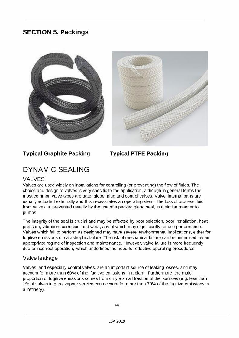
ESA 2019
44
SECTION 5. Packings
Typical Graphite Packing Typical PTFE Packing
DYNAMIC SEALING
VALVES Valves are used widely on installations for controlling (or preventing) the flow of fluids. The
choice and design of valves is very specific to the application, although in general terms the
most common valve types are gate, globe, plug and control valves. Valve internal parts are
usually actuated externally and this necessitates an operating stem. The loss of process fluid
from valves is prevented usually by the use of a packed gland seal, in a similar manner to
pumps.
The integrity of the seal is crucial and may be affected by poor selection, poor installation, heat,
pressure, vibration, corrosion and wear, any of which may significantly reduce performance.
Valves which fail to perform as designed may have severe environmental implications, either for
fugitive emissions or catastrophic failure. The risk of mechanical failure can be minimised by an
appropriate regime of inspection and maintenance. However, valve failure is more frequently
due to incorrect operation, which underlines the need for effective operating procedures.
Valve leakage
Valves, and especially control valves, are an important source of leaking losses, and may
account for more than 60% of the fugitive emissions in a plant. Furthermore, the major
proportion of fugitive emissions comes from only a small fraction of the sources (e.g. less than
1% of valves in gas / vapour service can account for more than 70% of the fugitive emissions in
a refinery).

ESA 2019
45
Some valves are more likely to leak than others: valves which are operated frequently, such as
control valves, may wear quickly and allow emission paths to develop. However, newer, low
leak control valves provide good fugitive emissions control performance. Valves with rising
stems (gate valves, globe valves) are likely to leak more frequently than quarter turn type
valves such as ball and plug valves.
The valve packing performs the role of the shaft seal and hence is a major influence on valve
leaking losses.
Compression packings
Control of fluid loss is essential to the successful operation of mechanical equipment used in
fluid handling. Various methods are utilised to control leakage at shafts, rods, or valve stems
and other functional parts of equipment requiring containment of liquids or gases.
The original and still most common of these sealing devices is the compression packing, so
called because of the manner in which it performs the sealing function. Made from relatively
soft, pliant materials, compression packings consist of a number of rings which are inserted into
the annular space (stuffing box) between the rotating or reciprocating member and the body of
t h e pump or valve. By tightening a gland follower against the top or outboard ring, pressure is
transmitted to the packing set, expanding the rings radially against the side of the stuffing box
and the reciprocating or rotating member, effecting a seal.
Compression packings are used in all process industry sectors to seal all types of media. They
are used in rotary, centrifugal and reciprocating pumps, mixers, agitators, dryers, valves,
expansion joints, soot blowers, and many other types of mechanical equipment. In this
document, the focus of attention will be on their use as valve packings.
Compression packings are relatively easy to install and maintain. With proper attention, a high
degree of successful operation can be anticipated.
• Successful sealing with compression packings is a function of several important and
related factors:
• careful selection of packing materials to meet the specific application requirements
• complete consideration of surface speeds, pressures, temperatures, and medium being
sealed
• proper attention to good installation and break-in procedures
• high standards of equipment maintenance
These factors are discussed in other segments of this publication and are covered in detail in
most of the product bulletins of the major packing manufacturers.
Also comprehensive information about compression packings can be found online from the joint
European Sealing Association (ESA) / Fluid Sealing Association of America (FSA), Compression
Packing Technical Manual (4th Edition).
Compression packings are made from various materials in a variety of shapes, sizes, and
constructions:

ESA 2019
46
Diagonal-interlock Braided Yarn Packings
This braid is designed for general service applications or as braided end rings on the top and
bottom of graphite die-formed tape rings for critical or control valve applications. When used
alone (straight-sets), required compression rates generally fall within a range from 25 to 30%.
When used as braided end rings on the top and bottom of a set of die-formed graphite tape
rings, the required compression rates are reduced to approximately 20%. These rings act as
anti-extrusion rings, wiper rings, and they compensate for any surface irregularities in the
bottom of the stuffing box as well as add resiliency to the set. For packings of 5 mm and under,
square or plait braid is normally used.
Flexible Graphite Products
Graphite packings are available in 3 different forms, as described below:
Flexible Graphite Die-Formed Rings
Typical Die-Formed Valve Ring Set
Valve stem packing rings manufactured from flexible graphite are die-formed from flexible
graphite ribbon. A predetermined length of flexible graphite tape is compressed in a properly
dimensional mould to the desired density resulting in a solid ring. Traditionally, the rings are of
square cross section and have a density of about 1.6 gm.cm-3 but square section rings can be
manufactured in density ranges from 1.2 - 1.8 g.cm-3. For such square section rings, especially
those of high density, the clearances of the ring with respect to the dimensions of the valve
stem and stuffing box are crucial for good sealing.
The recent trend in die-formed graphite rings has been to move away from such rings as
described above. One alternative consists of sets which are made up of rings of different

ESA 2019
47
densities, with the density used depending upon the position of the ring in the set. Another
alternative is to use rings which are not of square section. In both cases the purpose of the
design modification is to allow more of the effort from the gland follower nuts to be concentrated
in to radial force on to the stem and box wall to ensure a better seal, rather than being lost as
friction down the set.
Whatever form is used, for ease of installation when the valve bonnet cannot be removed, split
rings should be specified. These are available in a range of forms of cut construction. All the
forms of cut rings are designed to assist the user in obtaining a good quality seal.
Die-formed flexible graphite rings are available in commercial grade (95-98% purity) and nuclear
grade (99+% carbon purity), while low sulphur content forms are also available. The commercial
grade material makes up the vast majority of usage for industrial applications. Nuclear grades
are almost exclusively specified by the power generation industry for service in PWR
installations. The nuclear grade rings are made under stringent control procedures during
manufacturing.
Active or passive inhibitors may be applied during or after fabrication of each ring to insure
against corrosion and pitting of the valve stem.
Rings of a compatible braided material are recommended as anti-extrusion and wiper rings.
These latter rings should be selected from a material that will not relax or creep excessively
during service and thus allow the load from the follower nuts to be lost.
A prime consideration of the installation of such sets is that the load imposed upon the sets of
rings should not be so high that the valve stem cannot be operated!
Similarly, and perhaps of critical importance in an emergency, the hysteresis created by the
packing set of a control valve should not be significant in terms of the positioning of the stem.
To reduce this problem, various forms of modified design of die formed graphite rings are
available. Low density braided materials allowing the formation of rectangular rather than square
section anti-extrusion rings are also available for the same reason.
Expanded Graphite Tape
When flexible graphite die-formed tape rings are not available, one solution is to actually die-
form flexible graphite tape into packing rings in the stuffing box itself. Using this method, a
length of tape is wrapped around the valve stem or pump shaft until the build-up of the material
is sufficient to completely fill the packing space. The wrapped tape ring is then eased down into
the box and individually compressed to approximately 50% of the original tape width until the
stuffing box is completely filled. A top and bottom end ring of a compatible braided material
should be used to eliminate tape extrusion during the compression operation and in subsequent
service.
Other Graphite Packing Forms
In addition to die-formed graphite ring packings and expanded graphite tape packings, flexible
graphite packings are available in several other forms, including: braided packings, laminated
rings, wire reinforce flexible graphite yarn packings, and injection moulded rings.

ESA 2019
48
Installation of compression packings
The importance of packing the valve correctly cannot be over-emphasised. Many packing
failures are due to incorrect installation of the packing. The first step in getting the most out of a
valve packing is correct installation. The following steps have been devised to ensure effective
installation of packings on valves:
Remove the old packing from the stuffing box
Make sure the stuffing box is cleaned out and all remnants of the old packings are removed.
Ensure both shaft and sleeve are not damaged.
Clean stuffing box and shaft thoroughly
• Examine shaft or sleeve for wear and scoring
• Replace shaft or sleeve if wear is excessive
Use the correct cross section
To determine the correct packing size, measure the diameter of the shaft (inside the stuffing box
area if possible) and then measure the diameter of the stuffing box (to give the OD of the ring).
Subtract the ID measurement from the OD measurement and divide by two. The result is the
required size.
• Use correct cross section for stuffing box and shaft size
When using coil or spiral packing, always cut the packing into separate rings
Never wind a coil of packing into a stuffing box. Rings can be cut with butt (square), skive (or
diagonal) joints, depending on the method used for cutting. The best way to cut packing rings is
to cut them on a mandrel with the same diameter as the shaft in the stuffing box area. If there is
no shaft wear, rings can be cut on the shaft outside the stuffing box.
Hold the packing tightly on the mandrel, but do not stretch. Cut the ring and insert it into the
stuffing box, making certain it fits the packing space properly. Ensure the first ring is cut
carefully and tested on the stem. Each additional ring can be cut in the same manner, or the
first ring can be used as a master from which the balance of the rings is cut.
If the butt cut rings are cut on a flat surface, be certain that the side of the master rings, and not
the OD or ID surface, is laid on the rings to be cut. This is necessary so that the end of the rings
can be reproduced.
When cutting diagonal joints, use a mitre board so that each successive ring can be cut at the
correct angle.
It is necessary that the rings be cut to the correct size. Otherwise, service life is reduced. This is
where die-cut rings are of great advantage, as they give you the exact size ring for the ID of the
shaft and the OD of the stuffing box. There is no waste due to incorrectly cut rings.
• cut coil or spiral into separate rings
• cut the packing rings on a mandrel
• fit the first ring carefully and test on the stem
• use a mitre board to cut diagonal joints
• alternatively, use die-cut rings of the correct size

ESA 2019
49
Install one ring at a time
Make sure it is clean and has not picked up any dirt in handling. Seat rings firmly, Joints of
successive rings should be staggered and kept at least 90 degrees apart. Each individual ring
should be firmly seated with a tamping tool, or suitable split bushing fitted to the stuffing box
bore. When enough rings have been individually seated so that the nose of the gland will reach
them, individual tamping should be supplemented by the gland.
• install one ring at a time
• seat ring correctly
Last ring
After the last ring is installed, take up gland bolts finger tight or very slightly snugged up. Do not
jam the packing into place by excessive gland loading.
• after the last ring is installed, take up carefully
• do not load excessively
Slide gland forward until it makes contact with the packing
Make sure gland bolts are tightened up evenly. Tighten to the point when heavy resistance is
felt. During this time, turn the valve stem back and forth to determine ease of turning. Do not
torque down to the point where the stem won't turn.
• tighten the gland bolts evenly
• Take care not to tighten too much; ensure the stem can still turn!
Inspect the valve after it has been on line
If leakage is observed, adjust the gland in accordance with safe maintenance procedures and
manufacturer’s recommendations.
• inspect and adjust gland bolts if necessary
Current emission levels
Each valve type performs differently in terms of emissions, as indicated in this study by Cetim:
Application guide for BAT in valves
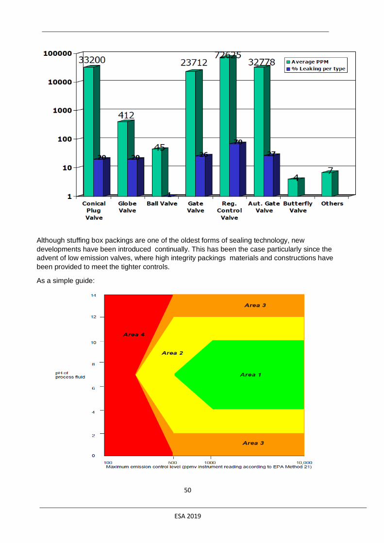
ESA 2019
50
Although stuffing box packings are one of the oldest forms of sealing technology, new
developments have been introduced continually. This has been the case particularly since the
advent of low emission valves, where high integrity packings materials and constructions have
been provided to meet the tighter controls.
As a simple guide:
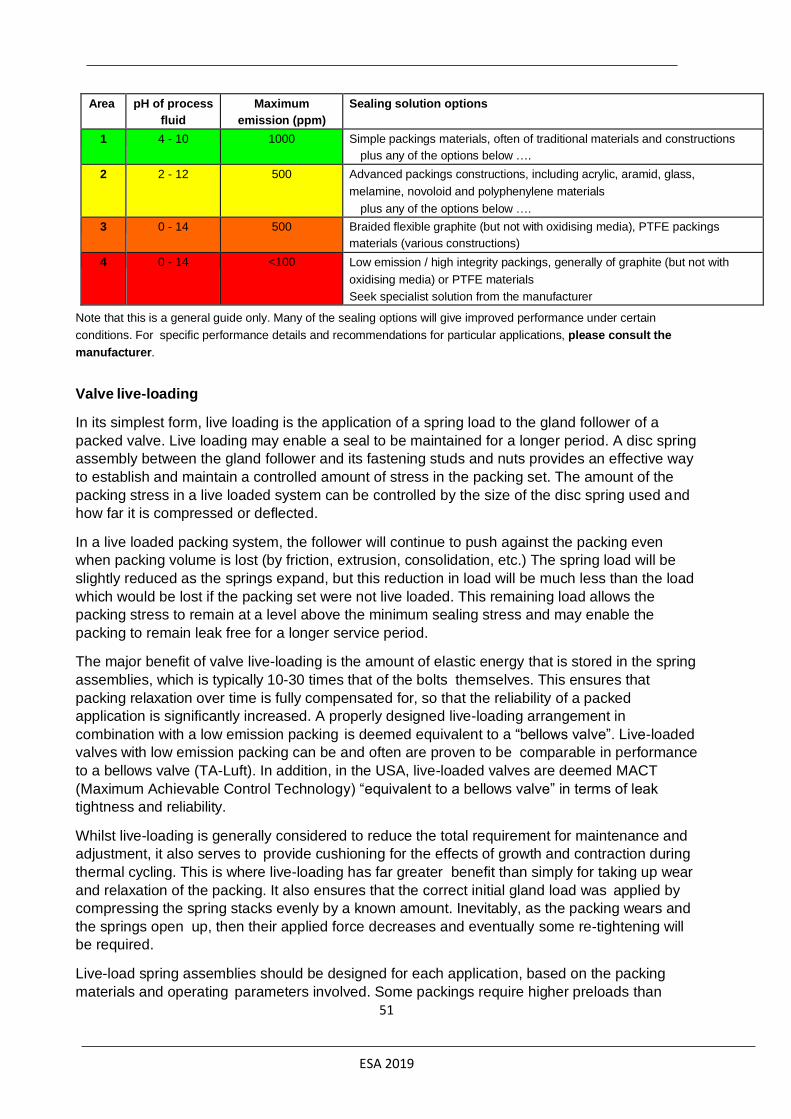
ESA 2019
51
Area pH of process
fluid
Maximum
emission (ppm)
Sealing solution options
1 4 - 10 1000 Simple packings materials, often of traditional materials and constructions
plus any of the options below ….
2 2 - 12 500 Advanced packings constructions, including acrylic, aramid, glass,
melamine, novoloid and polyphenylene materials
plus any of the options below ….
3 0 - 14 500 Braided flexible graphite (but not with oxidising media), PTFE packings
materials (various constructions)
4 0 - 14 <100 Low emission / high integrity packings, generally of graphite (but not with
oxidising media) or PTFE materials
Seek specialist solution from the manufacturer
Note that this is a general guide only. Many of the sealing options will give improved performance under certain
conditions. For specific performance details and recommendations for particular applications, please consult the
manufacturer.
Valve live-loading
In its simplest form, live loading is the application of a spring load to the gland follower of a
packed valve. Live loading may enable a seal to be maintained for a longer period. A disc spring
assembly between the gland follower and its fastening studs and nuts provides an effective way
to establish and maintain a controlled amount of stress in the packing set. The amount of the
packing stress in a live loaded system can be controlled by the size of the disc spring used and
how far it is compressed or deflected.
In a live loaded packing system, the follower will continue to push against the packing even
when packing volume is lost (by friction, extrusion, consolidation, etc.) The spring load will be
slightly reduced as the springs expand, but this reduction in load will be much less than the load
which would be lost if the packing set were not live loaded. This remaining load allows the
packing stress to remain at a level above the minimum sealing stress and may enable the
packing to remain leak free for a longer service period.
The major benefit of valve live-loading is the amount of elastic energy that is stored in the spring
assemblies, which is typically 10-30 times that of the bolts themselves. This ensures that
packing relaxation over time is fully compensated for, so that the reliability of a packed
application is significantly increased. A properly designed live-loading arrangement in
combination with a low emission packing is deemed equivalent to a “bellows valve”. Live-loaded
valves with low emission packing can be and often are proven to be comparable in performance
to a bellows valve (TA-Luft). In addition, in the USA, live-loaded valves are deemed MACT
(Maximum Achievable Control Technology) “equivalent to a bellows valve” in terms of leak
tightness and reliability.
Whilst live-loading is generally considered to reduce the total requirement for maintenance and
adjustment, it also serves to provide cushioning for the effects of growth and contraction during
thermal cycling. This is where live-loading has far greater benefit than simply for taking up wear
and relaxation of the packing. It also ensures that the correct initial gland load was applied by
compressing the spring stacks evenly by a known amount. Inevitably, as the packing wears and
the springs open up, then their applied force decreases and eventually some re-tightening will
be required.
Live-load spring assemblies should be designed for each application, based on the packing
materials and operating parameters involved. Some packings require higher preloads than

ESA 2019
52
others and therefore one spring assembly design will not suit all packing materials and
combinations.
Valve live-loading, in combination with a low emission, fire safe packing is a best available
technique for fugitive emissions control in VOC or hazardous services.
BAT for reduction in fugitive emissions from valves
As these can provide such an impact on plant emissions, valves should be a high priority for
attention. Best available techniques for valves include:
• correct selection of the packings material and construction for the process application
• correct installation of the packings material into the stuffing box
• regular monitoring, combined with a repair or replacement programme (LDAR)
• focus on those processes most likely to cause emissions (such as gas/light
liquid, high pressure and / or temperature duties)
• focus on those valves most at risk (such as rising stem control valves in
continual operation)
• For critical valves fit high-integrity packings. Many of these are available in
special constructions, using advanced technology materials, often specifically
formulated for environmental performance
• use live-loading, in combination with low emission, fire safe packings in VOC or
hazardous services
• where toxic, carcinogenic or other hazardous fluids are involved, fit diaphragm,
ball or bellows valves
Note that safety valves can be responsible for 10% of a plant’s fugitive leak losses. Losses are
higher where safety valves are exposed to pressure fluctuations, and when a safety valve has
activated. Therefore, safety valves should be checked after an emergency situation. Leaking
losses via safety valves may be reduced by the installation of rupture discs prior to the safety
valve to damp small pressure fluctuations. However, these fluctuations may pollute the valve,
making complete closure impossible. An additional measure is to connect safety valves to a
central flare system or another type of dedicated collection system (e.g. vapour
recovery/destruction unit).
RE-WORK OR NEW VALVE
In many instances it is questionable if an old and worn valve should be reworked or replaced by
a new one. Experience has shown that most valves can be upgraded to fugitive emission
requirements if the work is carefully done. But for smaller valve sizes there is always an
economic decision which has to be made. Experience at bigger plants has led to a general rule
being adopted: stainless steel valves smaller than DN 50 and carbon steel valves smaller than
DN 80 for use in fugitive emission applications should be replaced by new valves. In general,
replacement proved to be more economic than refurbishment.
If new valves are purchased it should be made sure that they are qualified or type tested
according to the latest fugitive emission valve standards like:
ISO 15848-1:2015 – Measurement, Test and Qualification Procedures for Fugitive
Emissions - Part 1: Classification system and qualification procedures for type testing of
valves

ESA 2019
53
This standard specifies testing procedures for evaluation of external leakage of valve stem
seals (or shaft) and body joints of isolating valves and control valves intended for application in
volatile air pollutants and hazardous fluids. End connection joints, vacuum application, effects of
corrosion, and radiation are excluded from this part of ISO 15848. Test media can be either
methane or helium. There are three leakage classes A, B and C with varying leakage levels
depending on the medium. There are different cycle classes as well as temperature ratings also.
API 624 (2014) – Type Testing of Rising Stem Valves Equipped with Graphite Packing for
Fugitive Emissions
The API 624 standard specifies the requirements and methane leakage criteria < 100 ppm for
fugitive emission type testing of rising and rising-rotating stem valves equipped with packing
previously tested in accordance with API Standard 622. The fugitive emissions testing includes
310 mechanical cycles with three thermal cycles from ambient to 260 °C at a pressure of 41.5
bar.
API 641 (2016) – Type Testing of Quarter-turn Valves for Fugitive Emissions
The standard specifies the requirements for type testing quarter-turn valves for fugitive
emissions and applies to all stem seal materials. The maximum allowable methane leakage rate
is 100 ppm and the number of 90° alternating rotations is 610. The pressure rating is 41.5 bar.
Test temperatures are rated up to 260 °C and above.260 °C with three temperature cycles.
Existing valves should be surveyed and refurbished with appropriate low emission packing or
sets. A packing or packing set should be used which is qualified according to:
TA- Luft (VDI 2440)
The German TA-Luft legislation defines emission levels for two temperature classes up to 250
°C and higher than 250 °C. The helium maximum leakage levels are 10-4 mbar*l*s/m for
temperatures up to 250 °C and 10-2 mbar*l*s/m for higher temperatures. Pressure ratings and
amount of cycles are based on the intended use of the valve. Testing is done according to VDI
guideline 2440 where packings or packing sets can be tested in a fixture or in a valve and
certification is issued by the manufacturer or independent test laboratories.
API 622 Rev. 3 (2018) – Type Testing of Process Valve Packing for Fugitive Emissions
This emission test which is performed by using a standardised test fixture. The testing can be
done by independent test laboratories which will provide certification stating the measured
methane emission levels of maximum 500 ppm. Test pressure is 41.5 bar with 5 temperature
cycles from ambient to 260 °C and 1510 cycles, with no re-torque allowed.
RE-WORKING OF VALVES
If a valve has to be re-worked the principle component in most cases will be the spindle. Due to
damage, the spindle may have to be replaced or machined slightly smaller. In the case of a
smaller spindle the packing set should be able to adapt to the changed dimensions. If this is not
possible new sets made from appropriate tooling have to be manufactured. It is also necessary
to ensure that the permissible clearance dimensions are not exceeded after the rework. If they
are appropriate metal disks should be used which can bridge the bigger clearances to reduce
any possibility of extrusion. Similar measurements apply for the enlargement of the stuffing box
bore due to corrosion problems. In addition bolts and nuts should be checked to make sure they
are still in proper working condition.
ESA 2019
54
SPRING LOADING OF GLAND BOLTS
If the valve is to be fitted with discs springs on the gland bolts, all the dimensions for the spring
assembly have to be measured. In some cases longer gland bolts are needed to accommodate
the disc spring solution. The protection of the springs by an additional cover bushing is also
recommended to guide the spring stack and to protect the springs against contamination. This
solution is very user-friendly because it is virtually impossible to over or under tighten the set.
Additionally there is a visual indication when the springs need to be re-tightened due to volume
loss of the packing set.
There should always be a cost evaluation to see if spring loading is necessary. It is
recommended if the valve is hard to access for re-tightening or if long maintenance free periods
are expected. Also if there are a high number of spindle movements or larger temperature
fluctuations during operation, a spring-energised system can guarantee more sustained and
consistent axial force retention and sealing performance.
INSTALLATION OF PACKING SETS
Maintenance Plan
The supply of detailed installation information and maintenance plans with all packings or
sealing sets is very important to ensure low emissions. All installation forces have to be
specified to achieve the best sealing performance. If torque measurement is not possible, a
specific dimension diagram for the compression-related tightening should be supplied. This
information will often be incorporated into customer standards. Experience shows that the
maintenance information needs to be easy to understand. Diagrams are more informative than
formulae or tables. If the instructions are too complicated they will not be followed and errors
can occur, resulting in poor seal performance.
Training of Maintenance Personnel
In situations where there are problems or dimensional deviations the experience and skill of the
maintenance personnel is crucial. In addition to the specific maintenance and installation
instructions seal suppliers will provide training seminars for end users or refurbishment
companies. Thorough theoretical and practical training is given which ensures that not only
standard situations but also potential problems are covered. Helpful is the ESA/ FSA pocket
guide on installation procedures as an ‘aide memoir’ to the trained operator.
LDAR PROGRAM
To ensure that the installed new or refurbished valves are working correctly and adhere to the
required leakage levels a LDAR (Leak Detection and Repair) program can be set-up. The EPA
(Environmental Protection Agency) in the US, the Environment Protection Agency (EPA) has
published a guide “Leak Detection and Repair – A Best Practice Guide” outlining the elements
of a good leak detection program. Technical guidance in regard to quality assurance of
emission monitoring systems can be found in “Technical Guidance Note (Monitoring) M20
Quality assurance of continuous emission monitoring systems - application of EN 14181 and BS
EN 13284-2”.

ESA 2019
55
Relative costs of Best Available Practice for valves
As mentioned in the section covering generic BAT, the cost of the actual sealing technology is
infinitesimally small when compared with the investment made in the plant as a whole. Indeed,
for many sealing technologies, the cost per unit may be in the region of a few cents, completely
insignificant when the total plant costs are considered. Importantly, the unit cost of the sealing
technology is overwhelmed completely by the labour costs required to fit the seal, let alone the
downtime of the plant. Consequently, the actual cost of the sealing device is immaterial in terms
of economic considerations for reduction in fugitive emissions. However, for the sake of
completeness, the following diagram provides an overview of the relative cost of the best
available sealing technologies for valves and the environmental impact of the sealing systems.
The challenges associated with valves are dependent upon the valve type, the application and
the sealing technology employed. The first matrix below represents the relative life-cycle costs
versus impact on the environment for on-off valves:
The matrix is intended to be used with typical valves but cannot be assumed to be applicable universally. The second matrix below represents the relative life-cycle costs versus impact on the environment for control valves:

ESA 2019
56
The matrix is intended to be used with typical valves but cannot be assumed to be applicable universally.
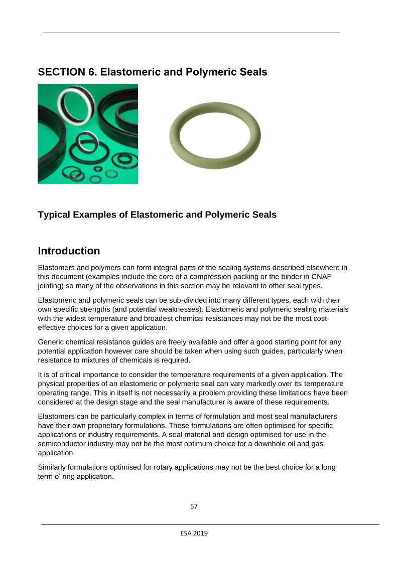
ESA 2019
57
SECTION 6. Elastomeric and Polymeric Seals
Typical Examples of Elastomeric and Polymeric Seals
Introduction
Elastomers and polymers can form integral parts of the sealing systems described elsewhere in
this document (examples include the core of a compression packing or the binder in CNAF
jointing) so many of the observations in this section may be relevant to other seal types.
Elastomeric and polymeric seals can be sub-divided into many different types, each with their
own specific strengths (and potential weaknesses). Elastomeric and polymeric sealing materials
with the widest temperature and broadest chemical resistances may not be the most cost-
effective choices for a given application.
Generic chemical resistance guides are freely available and offer a good starting point for any
potential application however care should be taken when using such guides, particularly when
resistance to mixtures of chemicals is required.
It is of critical importance to consider the temperature requirements of a given application. The
physical properties of an elastomeric or polymeric seal can vary markedly over its temperature
operating range. This in itself is not necessarily a problem providing these limitations have been
considered at the design stage and the seal manufacturer is aware of these requirements.
Elastomers can be particularly complex in terms of formulation and most seal manufacturers
have their own proprietary formulations. These formulations are often optimised for specific
applications or industry requirements. A seal material and design optimised for use in the
semiconductor industry may not be the most optimum choice for a downhole oil and gas
application.
Similarly formulations optimised for rotary applications may not be the best choice for a long
term o’ ring application.

ESA 2019
58
Seal manufacturers and/or third party test houses should be consulted if in any doubt. Involving
seal manufacturers and third party test houses at the earliest opportunity in a project and using
their specialised expertise gives the best chance of successful sealing.
Failure mechanisms
For a more detailed description of the failure mechanisms and recommendations to alleviate the
effects please refer to the ESA publication ‘Successful sealing with elastomers’
Compression Set
In general, compression set occurs with one or more of the following conditions:
• Molecular alignment/rearrangement occurs due to excessive temperature,
pressure and/or media permeation
• Molecular scission of the backbone chain or crosslink structure broken by the loads
placed upon them or as a result of chemical attack. This scission can also be caused by
elevated temperature
• Cross-links are generated within the elastomer material, which reduce the ability of the
elastomer to move and recover following deformation
Recommendations for optimising performance:
• Decrease the squeeze applied to the elastomer, but still ensure it will resist the initial
pressure impulses and allow for housing tolerances
• Reduce system temperature and/or pressure or protect seals from them.
• Change the material to one with higher compression set resistance under applicationconditions
Low Temperature Effects
In general, low temperature effects occur with one or more of the following conditions:
• Prolonged low temperature near or below the glass transition point (Tg) of the elastomer
• Low squeeze or low system pressure allows the elastomeric molecular chains to
rearrange to a low energy level state
• A material with a Tg close to the operating or ambient temperature is used
Recommendations for optimising performance:
• Select appropriate material for the given process conditions
• Increase the squeeze or use seal profile that will respond to system pressure at
operating temperature. If possible pressurize seal prior to reducing temperature.
• Provide localised heating to seal area
• Provide additional energisation device such as a spring
• When using lubrication ensure it is also suitable for the operating temperature
ESA 2019
59
High Temperature Effects
In general, high temperature failures occur with one or more of the following conditions:
• An elastomeric compound is selected which cannot withstand the upper operating limit or
excursion temperatures
• Process conditions have changed and a new material needs to be
selected
• Excessive frictional or localised heat is present
Recommendations for optimising performance:
• Appropriate choice of material type and grade for application temperature
• Avoidance of excessive friction by careful consideration of design, tolerances and
material grade
• Eliminate source of localised heat damage such as at the seal faces
• Remember that the presence of ozone and aggressive chemicals will accelerate thermal
degradation and the avoidance of such influences can postpone degradation
Thermal Cycling
In general, thermal cycling failure effects occur with one or more of the following conditions:
• Large temperature cycles are inherent to the system and/or process
• Hardware dimensions do not accommodate the thermal expansion of elastomer at high
temperature
• An improper material selection has been made
Recommendations for optimising performance:
• Isolate the sealing system from large thermal gradients
• Reduce the number of cycles between high and low temperatures
• Review the material properties to ensure the properties are appropriate at high and low
temperatures
Extrusion / Nibbling / Shaving Damage
In general, these failure modes occur with one or more of the following conditions:
• Excessive clearances
• High pressure
• Material too soft
• Degradation (swelling, softening, shrinking, cracking etc.) of the material by the system
fluid/circumstances
• Irregular clearance gaps caused by eccentricity
• Increase in clearance gaps due to excessive system pressure e.g. ballooning of cylinder
bore
• Improper size (too large) seal installed causing groove overfill
Recommendations for optimising performance:
• Decrease clearance by reducing machining tolerances.

ESA 2019
60
• Use back-up rings.
• Check seal material compatibility with system fluid/circumstances
• Increase rigidity of metal components.
• Replace current seal with a harder seal • Break sharp edges of gland to a minimum radius 0,2mm
• Insure installation of proper size seal.
• Use alternative seal profile.
Spiral twist / rolling
In general, this failure modes occur with one or more of the following conditions:
• Over-compression of part of the elastomer • Dynamic movement of the elastomer particularly in reciprocating applications
• Installation of elastomer over shaft
• Small O-ring cross section to diameter ratio
Recommendations for optimising performance:
• Improve surface finish of sealed assembly at dynamic interface (Cylinder Bore, Piston
Rod)
• Check for out-of-round components (Cylinder Bores especially)
• Provide proper lubrication. Consider the use of internally lubricated O-rings
• Replace with a harder, more rigid O-ring
• Increase the cross section to diameter ratio
• Consider use of alternate seal shapes, for example X-rings, D-seals or T-seals
Installation and/or port damage
In general, this failure mode occurs with one or more of the following conditions:
• There are sharp corners on mating metal components such as the seal gland or
threads over which the seal must pass during assembly
• Insufficient lead-in chamfer
• Blind grooves in multi-port valves
• Oversize seal on piston seal application
• Undersize seal on rod application
• Seal twisted/pinched during installation
• Seal not properly lubricated before installation
• Seal dirty upon installation
• Seal gland and/or other surfaces over which seal must pass during assembly
contaminated with metal particles
Recommendations for optimising performance:
• Break all sharp edges on metal components
• Provide a 15 to 20° lead-in chamfer
• Check all components for cleanliness before installation
• Tape the threads over which the seal will pass
• Use a seal lubricant
• Check seal to ensure correct size and material

ESA 2019
61
• To prevent damaging of seals during assembly, chamfers are necessary on all
leading edges. All edges must be free from burrs and sharp edges bevelled.
Chemical Degradation
In general, this failure mode occurs with one or more of the following conditions:
• The energy in the system activates or maintains chemical reactions, to either make or
break bonds. This is typically in the form of excessive temperature
• The sealing fluid is an easily polymerising fluid such as styrene or acrylic acid
• The density of the elastomer is low, or highly permeable to the sealed medium
• The backbone structure, plasticiser, filler and/or cross-links of the elastomer is
susceptible to chemical attack by the sealed fluid.
Recommendations for optimising performance:
• Reduce the permeability of the elastomeric material when sealing highly polymerising fluids
• Verify the fluid is compatible with the elastomer backbone structure, plasticiser,
filler and/or cross-links
• When possible reduce temperature in the sealing system below levels where
reactions occur
• Consider the use of a barrier fluid to isolate the elastomers from the aggressive fluid
Compression fracture
In general, this failure mode occurs with one or more of the following conditions:
• The initial compression caused by the hardware induces high strain
• High temperatures are found in the system
• Initial volume fill is too low • The surface finish of the compression surfaces is poor
• The system is exposed to rapid gas decompression (RGD)
Recommendations for optimising performance:
• Reduce the initial compression
• Reduce the temperature in the system
• Reduce the width of the groove
• Improve surface finish conditions of the hardware
• Control the pressure losses in the system to a level below which RGD occurs
Dieseling / Air entrainment
In general, this failure mode occur with one or more of the following conditions:
• Air / gas entrapment due to pressurising or improper venting
• Process fluid has a low auto-ignition temperature and/or allows air to dissolve easily
Recommendations for optimising performance:
• Minimize the presence of air in the system.
• Provide venting
• Use single-acting seals where appropriate
• Consider using a bladder to separate pressurising air and fluid
Short Stroke Failure

ESA 2019
62
In general, this failure mode occur with one or more of the following conditions:
• Lubrication to the sealing surface is inadequate
• Excessive force is placed on the sealing surface
Recommendations for optimising performance:
• Ensure a minimum stroke length of 2.5 times the stack depth to provide lubrication to allcontact lips
• Use shallow seals, even single element (unit) seals, as multi-lip packings can reduce seallife and cause premature failure.
Pressure trapping
In general, this failure mode occurs with one or more of the following conditions:
• Pairs of double-acting seals are used in a reciprocating application
Recommendations for optimising performance:
• Two double-acting seals should never be used in series
• If opposed seals are necessary then it is essential that at least one of them is a true
single-acting seal in order that any inter-seal pressure build-up is automatically vented.
Bunching
In general, this failure mode occurs with one or more of the following conditions:
• Over compression caused by system or chemical interactions
• Rotary or swivel motion is present in the system
• High friction limits elastomers motion
• Small cross section to seal diameter ratio
Recommendations for optimising performance:
• Lubrication of the seal surfaces on assembly or the use of low friction seals such as
rubber or spring energised PTFE seals
• The introduction of reinforcement into elastomeric seals can give increased stiffness
which resists the bunching effect.
• The use of a larger cross section can also give increased stiffness which resists thebunching effect.
Wear and fatigue
In general, this failure mode occurs with one or more of the following conditions:
• The velocity of the lubricating fluid film is sufficient to cause wear
• The elastomer is incompatible with either the lubricant or sealing fluid
• The surface finish of the hardware is poor
• Contamination in the sealing fluid or lubricant
• Excessive temperature due to friction
Recommendations for optimising performance:

ESA 2019
63
• Select the appropriate elastomer type and grade for the operating conditions
• Ensure that the seal does not operate outside its design conditions
• Ensure contacting surfaces are of the correct surface finish
• Ensure any lubrication is of the correct type for the conditions and elastomers used and
that hydrodynamic films are maintained by correct control of speed and lubrication.
• Ensure all good fitting and operational practice is maintained to avoid the introduction
and generation of contaminants
Volume Change
In general, this failure mode occurs with one or more of the following conditions:
• Loss of physical properties
• Seal extrusion• Overfill of the seal housing/groove
• In extreme cases, fracture of the metal hardware
Recommendations for optimising performance:
• Select the appropriate elastomer type and grade for the operating conditions
• Ensure any swell will be accounted for in the design of the seal housing/groove
Storage and handling of elastomeric and polymeric seals
These guidelines make use of the relevant sections of:
• BS ISO 2230: 2002. Rubber Products - Guidelines for storage
• BS 4F 68: 2002 - Controlled storage for vulcanised rubbers.
Damage resulting from poor storage and handling procedures can be manifested in the following ways:
A. Accelerated oxidative degradation
Oxidative aging will occur slowly over time whenever a rubber is in direct contact with
oxygen or ultraviolet radiation from the sun. Oxidisation will lead to chain scission, so
weakening the material by lowering the molecular weight, and cracks start to grow in the
regions affected.
Being stored at too high a temperature and the presence of certain metals or other
contaminants can accelerate the oxidative process.
B. Ozone degradation
Ozone is formed when oxygen molecules absorb the sun’s radiation, split into free radicals and
recombine with other oxygen radicals to form a triatomic molecule of oxygen, O3. It is a
powerful oxidizing agent which attacks any unsaturated bonds within the polymer, leading to
chain scission. This causes the polymer to lose its strength and, cracks will from the surface at
right angles to the strain, under strains of only 1%.
The kinetics of this reaction are increased as temperature is raised above 25°C or when the
rubber is in contact with catalytic metals/contaminants.
C. Hydrolysis

ESA 2019
64
Hydrolysis is technically a chemical reaction with water but the reaction is so slow that it is only
when there is an acid or alkali present to act as a catalyst that much concern is necessary.
Hydrolysis is of particular importance to Fluorocarbons and Nitriles but is also relevant to
other elastomer types.
D. Swelling
Any liquid or vapour introduced by humidity or contaminants, given enough time will diffuse
into and be absorbed within the polymer, forcing the macromolecules apart and causing the
elastomer to swell. This increase in molecular separation results in a reduction in the
secondary bonding forces, making the material softer. An elastomers susceptibility to swelling
depends on the similarity of the chemical structure between the solvent and rubber. The
greater the similarity the more likely the elastomer will swell. Temperature will also affect
swelling and a higher temperature will increase the rate at which the solvent is dissolved.
E. U.V degradation
U.V light is absorbed by rubbers removing an electron from a specific atom converting it into a
positively charged ion. There is then a rearrangement of atoms at this point and either chain
scission or cross linking will occur leading to either a loss of strength or hardening and
cracking.
F. Low temperature embrittlement
When rubbers are stored in cold conditions the temperature of the rubber may fall below its
glass transition point, Tg when it will become glassy and brittle. Its toughness is lost and any
deformation incurred while in this state will be plastic and permanent. Providing the rubber is
not damaged whilst cold, embrittlement is fully reversible by warming the rubber to a
temperature above its Tg.
G. Chemical degradation
Chemicals can attack double bonds in the rubber molecular structure causing chain scission
and new chemical bonds to be formed which harden the material. Chemicals can also
cause/exacerbate swell and hydrolysis.
Factors affecting the likelihood of deterioration during storage and handling:
H. Packaging
Contact with light , U.V, oxygen, ozone or other contaminants that cause hydrolysis or chemical
degradation, such as oil/grease/water vapour etc can be prevented by enclosing rubber
products in individually sealed, clean, black, dry, and preservative free packages in an
atmosphere of less than 65% humidity. Packaging should be completed as soon as is practical
after the final vulcanisation processes so that this protection in place before any contact can
occur.
Polyethylene, polyethylene coated Kraft paper and aluminium foil would make good packaging
materials but PVC film or film containing plasticisers should not be used.
ESA 2019
65
I. Induced stresses
Induced stresses as a result of deformation during storage will accelerate the degradation
processes. Therefore components should not be stored in a deformed, twisted or highly loaded
state.
Where it is not possible to store components in a free state, large rings for example, they
should be coiled into three equal superimposing loops to avoid twisting and laid flat. They
should not be hung on hooks.
Storage conditions
To minimise degradation, rubber products should be stored under the following conditions.
1. Protected from all sources of natural and artificial light especially that having a highultraviolet (UV) content.
2. At a temperature below 25ºC and in area free from condensation. Should items bestored below 15ºC then special care will need to be exercised in their handling, refer toISO 2230.
3. Well away from any sources of ionising radiation and from electrical equipment likely togenerate ozone.
4. By protecting products and packaging from distortion, stresses and other damage.5. By preventing direct contact with certain other materials, including all liquids, vapours,
semi-liquids and metals, in particular copper, magnesium and iron. The only exceptionbeing when one or more are supplied as an integral part of the component.
6. By resealing protective packaging and retaining identification labels for remainingproduct components after removing others for use, when contained in the samepackaging.
7. By using the oldest products first, i.e. those with the earliest cure date.
The above guidelines form an outline of storage requirements. Complete
recommendations for the controlled storage and packaging of vulcanized rubber and
rubber products can be found in ISO 2230.
STORAGE LIFE
STORAGE LIFE IS THE MAXIMUM PERIOD OF TIME THAT A PRODUCT, SUITABLY
PACKAGED, MAY BE STORED BEFORE BEING REGARDED AS UNSERVICEABLE FOR
THE PURPOSES FOR WHICH IT WAS MANUFACTURED. THE STORAGE LIFE OF
RUBBER PRODUCTS DEPENDS UPON THE STORAGE CONDITIONS AND THE TYPE OF
RUBBER INVOLVED.
In terms of general storage, vulcanised rubbers are classified into 3 groups, according to their
susceptibility to deterioration.
Initial Storage Period
The initial storage period is the maximum time, from date of manufacture, that a product may be stored before being inspected or re-tested. For products stored in accordance with the above guidelines, the initial storage period from date of cure for each type of rubber is shown in the table below.

ESA 2019
66
Extension Storage Period
The extension storage period is the period for which a product may be stored after the initial storage period before further inspection or re-testing is required. Rubber products still in storage at the end of their initial storage period may have their storage life extended, provided they are examined and found to be in good condition. The examination of a representative sample from each item (product type and cure date) shall
include visual inspection for the following defects: -
1. Physical damage, surface hardening, softening or tackiness2. Permanent set or distortion3. Surface cracking, which if present is more clearly visible if the product is gently
flexed. Whilst cracking will normally be visible to the naked eye, a magnification of10 times is recommended.
If none of the above defects are present it can be assumed that the product is still in good
condition. For products found to be satisfactory, provided the above storage conditions are
maintained (including repackaging of examined products), the extension storage period is as
shown in the table below.
Group Rubber Acronym Initial Storage (years)
Extension (years)
A Natural NR 5 2
A Butadiene BR 5 2
A Synthetic isoprene IR 5 2
A Styrene butadiene SBR 5 2
A Polyester and polyether urethane
AU/AE 5 2
B Acrylonitrile butadiene
NBR 7 3
B Carboxylated and hydrogenated
NBR
XNBR/HNBR 7 3
B Polyacrylic ACM 7 3
B Chloroprene CR 7 3
B Isobutylene isoprene
IIR 7 3
B Halogenated IIR BIIR/CIIR 7 3
C Chlorosulphonated polyethylene
CSM 10 5
C Ethylene propylene/diene
EPR/EPDM 10 5
C Fluorocarbon FKM 10 5
C Silicone MQ/FMQ/PMQ /VMQ/PVMQ
10 5
Note: It is recommended that any product taken from storage should be inspected, as detailed
above, prior to being put into service.
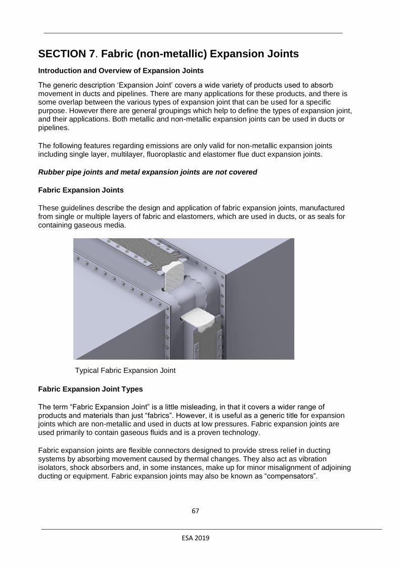
ESA 2019
67
SECTION 7. Fabric (non-metallic) Expansion Joints
Introduction and Overview of Expansion Joints
The generic description ‘Expansion Joint’ covers a wide variety of products used to absorb movement in ducts and pipelines. There are many applications for these products, and there is some overlap between the various types of expansion joint that can be used for a specific purpose. However there are general groupings which help to define the types of expansion joint, and their applications. Both metallic and non-metallic expansion joints can be used in ducts or pipelines.
The following features regarding emissions are only valid for non-metallic expansion joints including single layer, multilayer, fluoroplastic and elastomer flue duct expansion joints.
Rubber pipe joints and metal expansion joints are not covered
Fabric Expansion Joints
These guidelines describe the design and application of fabric expansion joints, manufactured from single or multiple layers of fabric and elastomers, which are used in ducts, or as seals for containing gaseous media.
Typical Fabric Expansion Joint
Fabric Expansion Joint Types
The term “Fabric Expansion Joint” is a little misleading, in that it covers a wider range of products and materials than just “fabrics”. However, it is useful as a generic title for expansion joints which are non-metallic and used in ducts at low pressures. Fabric expansion joints are used primarily to contain gaseous fluids and is a proven technology.
Fabric expansion joints are flexible connectors designed to provide stress relief in ducting systems by absorbing movement caused by thermal changes. They also act as vibration isolators, shock absorbers and, in some instances, make up for minor misalignment of adjoining ducting or equipment. Fabric expansion joints may also be known as “compensators”.

ESA 2019
68
They are fabricated from a wide variety of materials, including synthetic elastomers, fabrics, insulation materials and fluoroplastics, dependent upon the design. The designs range from a single ply to complex, multi-ply constructions attached to metal frames for operation under extremes of temperature or corrosion.
By the nature of the materials it is possible to design to specific shapes and sizes, generally without the constraints of tooling or moulds, and nearly all fabric expansion joints can be manufactured:
Circular or Rectangular Belt or flanged type
Belt type expansion joints provide the most effective joint from both a manufacture and attachment point of view. In these joints, the materials are subject to minimum stress until moved under operating conditions, and the airflow over the seal outer cover is largely uninterrupted. Frames for belt type expansion joints can be slightly more complex than for flanged expansion joints, but this is offset by the ease of repair or replacement of the flexible element.
Flanged type expansion joints offer the duct designer the simplest methods of attachment, but the nature of their construction restricts their use at higher temperatures. For multi-layer expansion joints where there are more than 3 or 4 plies of material, the fabrication of the flange restricts the available movement, and necessitates deeper flanges and a wider breach opening.
Fugitive Emission Factors
The design and selection of the Expansion Joint is critical and needs to take into account all the process variables which are in the questionnaire in the Selection section of this document. After evaluating the information supplied the manufacturer of the Expansion Joint will supply the design best suited for the application.
Typically the main emissions would arise from the Clamping area shown as A in the following diagram. Over time this will also include the flexible element shown as B.

ESA 2019
69
Factors for actual emissions
A: Clamp bar, duct flange, fasteners, bolt spacing B: Quality and quantity of sealing- and insulation layers C: Media, pressure, temperature D: Installation, Inspection, maintenance
The quantity of fugitive emissions will be influenced by the base design of the clamping bar, duct flange, fastener and bolt spacing (Factor A), material quality, and makeup of the layers (Factor B) in the expansion joint. Equally the actual operation conditions and cycles (Factor C). Proper installation, regular visual inspections and maintenance (Factor D) will increase the life and ensure maximum leak-tightness.
Expansion Joint Technology
Expansion joints provide flexibility in ductwork and are used to allow for 4 main situations:
• expansion or contraction of the duct due to temperature changes
• isolation of components to minimise the effects of vibration or noise
• movement of components during process operations
• installation or removal of large components, and erection tolerances
The benefits of fabric expansion joints include:
Large movements in a short length – this requires fewer expansion joints, reducing the overall number of units and providing additional economies.
Ability to absorb simultaneous movements easily in more than one plane – this allows the duct designer to accommodate composite movements in fewer (and simpler) expansion joints.
ESA 2019
70
Very low forces required to move the expansion joint – the low spring rate enables their use to isolate stresses on large, relatively lightweight, equipment. A particular example is a gas turbine exhaust, where it is crucial to minimise the forces from the duct expansion on the turbine frame.
Corrosion resistant materials of construction – modern technology materials enable the use in aggressive chemical conditions.
Noise and vibration resistance – fabric expansion joints provide a high degree of noise isolation and vibration damping.
Ease of installation and maintenance.
Minimal replacement cost – the fabric of the expansion joint assembly can be replaced simply and economically.
Design freedom – fabric expansion joints can be tailored to suit the duct application, with taper, transition or irregular shape, so allowing the designer the maximum variety of options.
Thermal breaks – self-insulating properties of the fabric allow simple hot-to-cold transition.
For further detailed information please refer to ESA Engineering Guide publication No 011/01
Selection
Common designs are described in more detail in the ESA Engineering guide.
The manufacturer will require some detailed information in order to design the most suitable
Expansion Joint for the application. Please note that there may be several alternative designs
which could be used but the manufacturer will advise you on this.
A typical industry design questionnaire is the following:
RAL TI-004
These are also available from all ESA and RAL Expansion Joint manufacturers of this product.
Expected Emission Rates.
Flue Gas Tight Leakage Standard: RAL TI – 002
This is the most commonly used test standard. Typical Leak rates can only be verified in lab
conditions as there are so many variables. The RAL leak rates are typically below 10l/min/meter
of gas. The only practical method on site is a bubble test.
Nekal Gas Tight Leakage Standard RAL TI – 003 is a higher tightness class for toxic or
critical media.
The test methodology is described in RAL TI-005
ESA 2019
71
Installation
Poor Installation will lead to higher leak rates and premature failure. Correct Installation
procedures can be found in ESA Fabric Expansion Joints - Installation Guide publication
No 015/04 and RAL Installation document TI 010
The training of installation technicians is critical if reductions are to be minimised. Ideally an
experienced person should supervise the installation process.
Note: This type of structure wears and will require regular visual inspection and will require
complete replacement, the timing of replacement depends on many factors and cannot be
predicted but usually a visible inspection will be acceptable.
Maintenance
Regular maintenance is required to prevent or minimize emission and leakage during operation
as well as to extend the lifetime of the product. For frequency of inspections and measures refer
to RAL – TI 012
ESA 2019
72
SECTION 8. Methods of Measuring Emissions Accurately
MONITORING TO DETERMINE LEAKING LOSSES Leaking losses are often hard to determine since there are many potential sources and they are
very dependent on how well the installation is operated, maintained and inspected.
Some important causes of leaking losses are:
• ill-fitting sealing elements
• installation
• construction faults
• wear and tear
• corrosion
• ageing
• equipment failure
• contamination of the sealing element
• excursions out of normal process conditions
• poor maintenance procedures
Leaking losses are generally higher from dynamic equipment (compared with static equipment)
and from older equipment.
Leaking losses are also very dependent on process conditions:
• pressure
• temperature
• speed of pumps and compressors
• choice of sealing solutiono Single Mechanical Seals leak more than double seals (where barrier fluid is the
leakage to atmosphere)o Gaskets and Packings need careful selection to have correct style selected for
the particular service.o All seals need careful and correct fitting.
A structural reduction of leaking losses is only possible when insight on the leaking losses is gained. There are various methods to determine the leaking losses.
There are several accepted methods for measuring leakage. The most commonly followed technique used on Chemical plants, Refineries and oil and Gas upstream production facilities is the US Environment Protection Agency EPA Method 21.
There are several other methods available. These include:
• CWP 453/R/95 where EPA method 21
• IR OGI Alternative Work Practice (AWG), using an Infra-Red camera
• API 220
• EPA 6560-50-P 2008 where two measures Parts per Million PPM) and KG/Hr.
• Netherlands Technical Agreement (NTA) NTA 8399, which focusses on VOC emissionsand takes into account Air Temperature; Wind Speed; Humidity and Cloud cover.
• DIAL LIDAR technique.
Monitoring frequency is a key issue to be agreed, as are acceptable leakage rates.
ESA 2019
73
The simplest way to estimate the leaking losses is by multiplying the number of each type of equipment by an emission factor for that type of equipment. This method can be applied to obtain a general estimation of the emissions without measurements. Please note that emission factors are not intended as an accurate measure of a single piece of equipment, and do not reflect the site-specific conditions of process units.
Many companies determine their leaking losses by calculations or estimations based on
measurements, but it is hard to measure all possible sources in a large plant (possibly tens of
thousands) and not all sources are accessible. In most cases, a representative sampling of
sources will suffice to estimate or calculate the leaking losses of the plant. The number of
samples depends on the kind of process fluids in the plant and the kind of equipment (the
sources). However, to provide the best estimate of emissions, every potential “source” on a site
must be monitored (usually using a “sniffing” process such as EPA Method 21).
Leaking losses from equipment and fittings can be significantly reduced by the use of monitoring and maintenance programmes such as LDAR (Leak Detection and Repair). Leaks are detected by monitoring equipment and repairs must be carried out if the leakage rate exceeds certain levels. A leak detection and repair programme consists of using a portable VOC detecting instrument to detect leaks by “sniffing” (usually, according to EPA Method 21) during regularly scheduled inspections of valves, flanges, and pump seals. Leaks are then repaired immediately or are scheduled for repair as quickly as possible. An LDAR programme could reduce fugitive emissions by 40% to 60%, depending on the frequency of inspections, the process conditions and the fluid emitted.
LDAR can be structured to meet local requirements using appropriate techniques, frequencies and priorities, but in all cases the largest losses should be tackled first. Such programmes have shown that gland leaks on valves and pumps are often responsible for the majority of leaking
releases.
Monitoring has been identified as a common activity across industrial processes and is the subject of a official IED Reference document (REF) entitled “JRC Reference Report on Monitoring of Emissions to Air and Water from IED Installations ”. The document provides generic information on sampling and analysis and should be read in conjunction with other industry-specific BREF notes.
Monitoring is often expensive and time consuming, so the objectives should be clear when a programme is established. Process operators and regulators may use monitoring to provide information on a wide range of topics.
For this Fugitive Emissions Reduction guidance note on sealing technologies, the key objectives of monitoring are:
• Process control and optimisation; monitoring is the way used to control a process by
means of following-up significant physical and chemical parameters. By control of the
process, it is meant the application of conditions in which the process operates safely
and economically.
• Emission monitoring; emissions to air and water are characterised and quantified to
provide a check on compliance with permit requirements (or other performance
measures). This also provides a check of whether all significant emissions are covered
by the permit and can indicate the effectiveness of abatement techniques and sealing
technologies employed. For the latter, emission monitoring can give an assessment of
leaking losses and will indicate equipment where attention is required. Wherever
ESA 2019
74
possible, data should be collected on flow rates to enable the calculation of mass
discharges.
• Occupational health and safety; tests to identify the short and long term risks to
personnel from work place exposure.
• Troubleshooting; intensive, short duration programmes may be used to study specific
topics.
• A monitoring programme to address any of these topics will need to stipulate the
frequency, location and method of both sampling and analysis. Monitoring usually
involves precise quantitative analysis, but simple operator observations (either visually
or by smell) can also play an important role in the detection of abnormal releases. The
results of monitoring programmes should be actively utilised; records of results should
be kept for trend analysis and diagnostic use.
Some estimates have been made of the costs of monitoring schemes. For example, a simple
LDAR scheme, involving the annual inspection of gas and volatile liquid service components, is
estimated to have a net annualised cost of over €25K per year (for a typical plant handling
20000 tpa of gaseous hydrocarbon streams and 30000 tpa of volatile liquids).
DIAL LIDAR technique. A strategy to reduce VOC emissions may include a complete
inventory and quantification by a DIAL LIDAR technique (differential absorption light detection
and ranging). In some cases, emissions estimates using “sniffing” methods give lower
emissions than estimates based on the DIAL monitoring. In some cases, the discrepancies are
very large. For example, by using the method for estimating fugitive emissions proposed by
EPA "Workbook for estimating fugitive emissions from petroleum production operations 1992",
the emissions from the process area at an average European refinery have been estimated to
be 125 tonnes per year. Extrapolations of the DIAL measurements to a yearly emission give
emissions of 500- 600 tonnes per year.
Note that most reported fugitive emissions are calculated rather than monitored (measured), but
unfortunately, correlations are often dubious! Equally, not all calculation formats are
comparable. For example, monitoring at well-maintained plants in the Netherlands shows that
the average emissions factors are generally higher than measured (monitored) values.
Leaks are then repaired immediately or are scheduled for repair as quickly as possible. An
LDAR programme could reduce fugitive emissions by 40 to 60%, depending on the frequency of
inspections, the process conditions and the fluid emitted.
Measuring leakage
The current onsite method of measuring PPMv values using an Organic Vapour Analyser, commonly known as a SNIFFER is used due to the EPA Method 21 being more practical.
Method 21 Survey Specifics
• 8.3.1 Type 1 -- Leak Definition Based on Concentration. Place the probe inlet at the
surface of the component interface where leakage could occur. Move the probe along
the interface periphery while observing the instrument readout. If an increased meter
reading is observed, slowly sample the interface where leakage is indicated until the
maximum meter reading is obtained. Leave the probe inlet at this maximum reading
location for approximately two times the instrument response time. If the maximum
observed meter reading is greater than the leak definition in the applicable regulation,

ESA 2019
75
record and report the results as specified in the regulation reporting requirements.
Examples of the application of this general technique to specific equipment types are:
• 8.3.1.1 Valves. The most common source of leaks from valves is the seal between the
stem and housing. Place the probe at the interface where the stem exits the packing
gland and sample the stem circumference. Also, place the probe at the interface of the
packing gland take-up flange seat and sample the periphery. In addition, survey valve
housings of multipart assembly at the surface of all interfaces where a leak could occur.
• Other sub paragraphs discuss flange, screwed connections, etc
• Bagging method
– the leaking component is enclosed in a “bag” or tent
– An inert carrier gas (e.g., nitrogen) is conveyed through the bag at a known flow
rate.
– When the carrier gas attains equilibrium, a gas sample is collected from the bag,
and the TOC (total organic compounds) concentration of the sample is
measured.
Bagging Vacuum Method

ESA 2019
76
Bagging Blow-Through Method

ESA 2019
77
Table 2-2. Equipment Leak Rate for Petroleum and SOCMI Equipment
Note: kg/hr./source = kilograms TOC per hour per source a. Data reported in U.S. EPA, 1995b.b. SV is the screening value (SV, ppmv) measured by the monitoring device.c. The “other” equipment type was developed from instruments, loading arms, pressure reliefdevices, stuffing boxes, vents, compressors, dump lever arms, diaphragms, drains, hatches, meters, and polished rods. This “other” equipment type should be applied to any equipment other than connectors, flanges, open-ended lines, pumps, or valves. d. The light liquid pump factors can also be applied to compressors, pressure relief valves,agitators, and heavy liquid pumps.
• When a screening value is zero use the default zero in Table 2-2 to estimate TOC
emissions.
• When the meter is pegged (goes to the maximum) use the pegged values in Table 2-2
are used to estimate emissions.
– Note - one value for instruments with a maximum of 10,000 and another for
100,000
• The uncertainty of the correlations for any single measurement may be as much as a
factor of 3 higher or a factor of 10 lower than the actual but when summed over
thousands of components, the uncertainty in the cumulative total emissions is expected
to be much less.
– Example – Monte Carlo simulations of 100 leaking components using an
uncertainty of plus or minus a factor of 10, the uncertainty in the cumulative
emissions is approximately plus or minus a factor of 1.4
Hi-Flow Monitor
• High volume sample allows for direct measurement of mass
– Method 21 with an OVA is a point measurement

ESA 2019
78
Table 2-3. Screening Ranges Emission Factors a
a. Data reported in U.S. EPA, 1995.b. These factors are for non-methane organic compound emissions.c. These factors are for total organic compound emissions.
The EPA takes the recorded methane PPMv screening value (SV) and converts it to a mass emission rate (ER) in kg/hr using a correlation chart measured in real world plants.

ESA 2019
79
(see Protocol for Equipment Leak Emission Estimates)
The SV can be changed depending on the content of the leak media using a correction factor i.e. for different hydrocarbons and /or hydrocarbon mixes, but they then still use the same conversion method to get to a final kg/hr ER.
So when measuring in PPMv, the idea was always to end up finally with a mass flow rate. I.e. measuring PPMv was only to get to an indication of the mass flow rate.
The idea was that because there are measurements at lots of points when measuring a whole plant it is not necessary to be accurate, because it sorts itself out with the average over many measurements.
Now in labs it is possible to measure the mass flow rate directly and accurately, using either displacement of helium or methane. So there is no need to make many measurements. At these leakage levels mass spectrometers are not even required.
Therefore we should measure in mass flow rates and convert back to expected PPMv rates. Not measure in PPMv directly as that is, by the EPA's own admission, inaccurate unless done many times.
Also we all know the EPA also have a kg/hr level for a 0 PPM reading. It is about 5 x 10⁻⁷ kg/hr (~1.50e-4 mg/s) for "connections" this is all in the EPA document linked in the excel file.
For final limits for the test in Germany they like 0.01 mg/s Helium as a leakage allowance, using this EPA method that's a PPMv reading of around 20 PPM, our old limit of 0.1 mg/s would have been around 500 PPM.
While we want to follow EPA criteria that is used in the field (since that is mostly what end-users
care about), we don’t think laboratory tests need to be concerned with ”screening values” and
mass emission rates. While we are “sniffing” leaks, the method that we are proposing should be
capturing most, if not all the gas coming out, which is not the case for field screenings.
For methane testing. Most sensors being used report in PPMv. If they are calibrated according to API 622/624/641, then the sampling rate is standardisedd as 1000 cc/min. So the PPMv reading can be easily and accurately converted to a leak rate by dividing by 1000 for a cc/min leak. So 100 PPMv equals 0.1 cc/min leak rate. If mass flow is wanted, then multiply by the density of the gas. (.66mg/cc for methane)
For helium mass spectrometers, it is common to use flow standards to calibrate. The PPMv output given by machine is calculated from an average sampling rate. Pfeiffer samples at about 40 cc/min for sniffing. So a 100 PPMv concentration at a 40 cc/min sampling rate would equal 0.004 cc/min. Conversely, a 0.1 cc/min helium leak rate equals 2500 PPMv.
Optical Gas Imaging (OGI)
Advances in Optical Gas Imaging (OGI) Technology allows improved Leak Detection and
Repair (LDAR) surveys by more efficiently identifying fugitive sources. Unfortunately they are
not too good at quantifying emission rates. Other methods can be used when leak identified.
• An owner of an affected source who chooses to use the alternative work practice must
comply with the requirements of paragraphs (e) (1) through (e) (5).

ESA 2019
80
• (1) Instrument specifications: The optical gas imaging instrument must
comply with the requirements specified in paragraphs…
• (2) Daily instrument check: On a daily basis, and prior to beginning any leak
monitoring work, test the optical gas imaging instrument at the mass flow rate
determined in paragraph…
• (3) Leak survey procedure: Operate the optical gas imaging instrument to
image every regulated piece of equipment selected for this work practice in
accordance with the instrument manufacturer's operating parameters. All
emissions imaged by the optical gas imaging instrument are considered to be
leaks and are subject to repair.
• (4) Recordkeeping: Keep the records described in paragraphs…
• (5) Reporting: Submit the reports required in the applicable subpart.
Toxic Vapour Analyser
A common alternative is to use Toxic Vapour Analyser (TVA), which use photo ionisation detectors (PID). There is a further option using detectors that use the principle of Flame Ionisation (FID).

ESA 2019
81
SECTION 9. Appendix
FURTHER READING 1. Determination of emissions of flange joints in a chemical plant, K.Kanschik and H. Schmidt-Traub,proceedings of the 2
nd European Fugitive Emissions Conference, Düsseldorf (8 - 9 September 1998), published
by VDI-Verlag as VDI Berichte 1441(ISBN 3-18-091441-6), Düsseldorf 1998.
2. Control of Fugitive Emissions of Mechanical Seals, E Vanhie (Durametallic Europe NV), presented atthe Shaft Sealing Seminar of the I Mech E, London, February 1992.
3. Seal Systems for Emissions Control, W Key (BW/IP International Inc.), presented at the 11th
International Pump Users' Symposium, Houston, March 1994.
4. Seal Technology, a Control for Industrial Pollution, James P Netzel (John Crane Inc.), presented atthe 45th STLE Annual Meeting, Denver, May 1990.
5. Controlling Emissions to Atmosphere through the use of a Dry-sliding Secondary Containment Seal,P M Flach, J E Sandgren and D P Casucci (EG & G Sealol), proceedings of the 10
th International Pump Users'
Symposium.
6. Emissions of Hydrocarbons to the Atmosphere from Seals on Pumps and Compressors, B J
Steigerwald, Joint District, Federal and State Project for the Evaluation of Refinery Emissions, Report N°. 6,
NTIS N°- PB 216582, 1958.
7. BHRA Seals Survey: Part 1, Rotary Mechanical Face Seals, R K Flitney, B S Nau, BHRA Report CR
1396, February 1977.
8. Assessment of Atmospheric Emissions from Petroleum Refining, Radian Corporation, Vol. 1-4,Research Triangle Park, North Carolina, USA, Pub. N°- EPA - 600/2-80-075a-d, 1980.
9. CMA / STLE Pump Seal Mass Emissions Study, T Kittleman, M Pope, W Adams, proceedings of the
11th International Pump Users' Symposium, Houston, March 1994.
10. National Emission Standards for Organic Hazardous Air Pollutants for Equipment Leaks, Federal
Register, Vol. 59, No. 78, Subpart H, pages 19568 - 19587, April 1994.
11. Effectively Managing your Pump Seal Emissions, C J Fone (John Crane EAA), proceedings of the
Pump Performance and Reliability Conference, Aberdeen, October 1993.
12. Mechanical Seal Practice for Improved Performance, I Mech E, Mechanical Engineering Publications,
Second edition, 1992. ISBN 0 85298 806 0.
13. Guidelines for Meeting Emission Regulations for Rotating Machinery with Mechanical Seals,
Society of Tribologists and Lubrication Engineers, Special Publication SP-30, September 1990.
14. Guidelines for Meeting Emission Regulations for Rotating Machinery with Mechanical Seals,
Society of Tribologists and Lubrication Engineers, Special Publication SP-30, revised April 1994.
15. Measurement of Vaporised Leakage, Dr A Voigt (John Crane GmbH), presented at the STLE/ I Mech E
Environmental Forum, Pittsburgh, May 1994.
16. Canned Motor and Magnetically-coupled Pump Applications, Operations, and Maintenance in a
Chemical Plant, H Vollmtiller, W Seifert (Hoechst AG, Frankfurt) and K B Fischer (Hoechst-Celanese, Houston),

ESA 2019
82
proceedings of the 10th International Pump Users' Association.
17. The increasing pressures on Process Plant Operators and how Mechanical Seal Technology is
keeping pace, C J Fone (John Crane EAA), proceedings of the Process Pump Seminar, I Mech E, London, June
1991.
18. Zero Emission Solutions for Mechanical Seals on Light Hydrocarbons, N M Wallace and JAM ten
Houte de Lange (Flexibox International), proceedings of the 9th International Pump Users' Symposium, College
Station, March 1992.
19. A User's Engineering Review of Sealless Pump Design Limitations and Features, T Hernandez
(Exxon Chemical Company), proceedings of the 8th International Pump Users' Symposium.
20. Shaft Sealing Systems for Centrifugal and Rotary Pumps, API Standard 682, American
Petroleum Institute, September 1992 (First and Second Edition).
21. Die Bestimmung der Leakage von Gleitringdichtungen, G Knoll, H Peeken, R Schroder (Rheinisch-
Westfalische Technische Hochschule Aachen), VDMA-Projekt Literaturrecherche, February 1993.
23. Dry Gas Compressor Seals, P Shah, proceedings of the 17th Turbomachinery Symposium, College Station,1988.
24. Application of Dry Gas Seals on a High Pressure Hydrogen Recycle Compressor, D R Carter,
proceedings of the 17th Turbomachinery Symposium, College Station, 1988.
25. Design and Development of Gas Lubricated Seals for Pumps, J R Wasser (John Crane Inc.), R Sailer and
G Warner (GE Plastics), proceedings of the 11th International Pump Users' Symposium, Houston, March 1994.
26. Containment Seals for API 682 Second Edition, Peter E Bowden and Chris J Fone (John Crane EAA),
proceedings of the 19th
International Pump Users Symposium, Houston, 2002 February.
27. ISO 21049, Pumps-Shaft Sealing Systems for Centrifugal and Rotary Pumps, Published by Association
Francaise de Normalisation (AFNOR) for and on behalf of ISO, February 2004.
28. VDI Richtlinie 2440 Emissionsminderung Mineralölraffinerien, Gründruck, VDI-Verlag, Düsseldorf, 1999.
29. Ohne Pumpen läuft es nicht, Dr.Ing. Friedrich-Wilhelm Hennecke (Leiter der Fachwerkstatt für Pumpen,
Getriebe und Motoren, BASF AG, Ludwigshafen), Seal Forum, Issue 3, published by the European Sealing
Association and Fluid Sealing Association, Summer 2002.
30. ISO 15848-1:2015 Industrial valves -- Measurement, test and qualification procedures for fugitive
emissions -- Part 1: Classification system and qualification procedures for type testing of valves,
International Organisation for Standardisation, 2015
31. API 624 - Type Testing of Rising Stem Valves Equipped with Graphite Packing for Fugitive Emissions,
First Edition, American Petroleum Institute, 2014
32. API STD 641 - Type Testing of Quarter-turn Valves for Fugitive Emissions, First Edition, American
Petroleum Institute, 2016
22. Meeting New Safety Emission Standards in a Hydrocarbon Plant, D Brandt (Quantum Chemical Corporation) and JNetzel (John Crane Inc.), proceedings of the 66th Annual Fall Conference, Pacific Energy Association, Irvine, California, October 1991.

ESA 2019
83
33. API STD 622 - Type Testing of Process Valve Packing for Fugitive Emissions, Second Edition, American
Petroleum Institute, 2011
34. Valve stem leak-tightness test methodologies, Publication Report, published 2000 September by BHR
Group Ltd, Report CR7 132.
35. Leak Detection and Repair - A Best Practices Guide, Environmental Protection Agency, EPA-305-D-07-
001, 2007
36. Life-cycle cost and reliability for process equipment, H. Paul Barringer, proceedings of the 8th
Annual
Energy Week Conference and Exhibition (28 - 30 January 1997), organised by the American Petroleum Institute,
published by the American Society of Engineers and Penn Well Publishing.
37. Life-cycle cost estimator, software tool developed jointly by the Mechanical Seals Divisions of the Fluid
Sealing Association and European Sealing Association.
38. Gasket Handbook – 1st Edition 2017 Successfully sealing a bolted flange connection is dependent on allcomponents of a well-designed system working together, effectively and safely. This handbook includes guidance to plant engineers on specifying gaskets; maintenance operators on installing and trouble-shooting bolted flange connection leaks, as well as purchasing personnel on the important functional distinctions between various gasket types.
39. Flange Gaskets – Glossary of Sealing Terms Detailed guidance on the terminology and standardisationchallenges facing users of gaskets.
40. Gasket Installation Procedures. A guide to successful gasket installation. This document provides guidance tomaintenance operators, engineers and fitters to ensure successful gasket installation and assembly of bolted flange connections. It is intended to complement other plant-approved installation procedures. English language version. Published in collaboration with the FSA
41. Expansion Joints –Fitters Guide.This handy pocket sized guides are written for those physically installing theexpansion joints. Pictorial and easy to follow the guides ensure that the products are installed to best practice to
maximise the performance and lifetime of the product. Available in other languages.
42. Expansion Joints – Installation Guide This publication is focussed on the actual installation of the ExpansionJoint. Available in a variety of languages the guide assumes that the joint and its components are now at the point of
final installation.
43. Expansion Joints – Engineering Guide. This publication is aimed at engineers designing systems that includeexpansion joints. It contains details on typical designs, capabilities and design guidelines. Available in other languages.
44. Elastomeric & Polymeric Seals - Successful Sealing with Elastomers. This document offers guidance onhow to prevent seal failure through appropriate material selection and design.
45. Compression Packing Technical Manual 4th Edition 2019. Provides detailed information on compressionpackings and their components, with guidance on their selection and installation. A substantial revision of the 3rd edition which was published in 2008. English language version.
46. Pump and Valve Packing Installation Procedures. A guide to effective pump and/or valve packing installation. Thisdocument provides guidance to maintenance operators, engineers and fitters to ensure successful packing installation inpumps and valves.
Recommended