For Help Contact Information:
Harinath Reddy
Phone: +91-9502542081(IND) (Whats App, Viber)
phone: +1-2089086040 (US)
Email: [email protected]
System Design Process of Efficient Gas
Turbine Cycles
1 | P a g e
Table of Contents
1. Introduction.........................................................................................................................................3
2. Conceptual Design of Gas Turbine Cycles............................................................................................5
2.1 Overview of Conceptual System design.......................................................................................5
2.2 Conceptual system design of Efficient GTB (Gas Turbine Blades)................................................6
3. Preliminary system design of Gas Turbine blades...............................................................................9
3.1 Overview of Preliminary design...................................................................................................9
3.2 Preliminary design of proposed Gas turbine blade....................................................................11
3.2.1 System functionalities........................................................................................................11
4. Detailed design and development of Efficient Gas Turbine Blade System.........................................13
4.1 Overview of Detailed system design and development.............................................................13
4.2 Detailed design and development of Gas Turbine Blade System...............................................14
5. System test, evaluation and validation design of Gas Turbine Blade system.....................................17
5.1 Overview of System test, evaluation and validation design.......................................................17
5.2 System test and validation design of proposed efficient Gas Turbine Blade system.................19
6. Conclusion.........................................................................................................................................21
References.................................................................................................................................................22
2 | P a g e

1. Introduction
Project life cycle has a common set of tasks or activities irrespective of the development model
used and include user requirement analysis, client clarifications, design, development or
implementation, testing, bug fixing, deployment and maintenance. When the project life cycle
methods are calculated or rated for 100%, user requirement analysis and design of the project
occupies 50% and rest of the activities contributes balance towards project completion. User
requirement analysis and clarifications from the clients will the basic input to design of any
project, where the entire business logic analysis, interface analysis, application or equipment
working methodology analysis is estimated at the design stage of any project (Hewett, 2005).
Analysis of systems has significant impact over the design of any project with respective to the
system engineering and in general classification of the systems will provide the core
methodology or approach to design a specific project and the general classification is as provided
below
Human made Vs Natural systems
Conceptual Vs Physical systems
Open Vs Closed systems
Dynamic Vs Static systems
3 | P a g e

Based on the respective system categorization and analysis, design type is evaluated. System
engineering is the key principle used over the design analysis of any system and can be defined
as the means and approach followed to deliver a successful system. System design process of any
project considers the core system engineering principles and the respective disciplines. In general
system design of any project can be evaluated various level and have four important categories in
this context as provided
Preliminary system design
Conceptual system design
System validation, test and evaluation
Detailed design and development (Wong, 2008)
Type of design chosen or evaluated against the system design of a particular project depends on
the complexity and architecture of the respective project. System engineering principles are
applied against the type of a specific design approach or methodology and various constraints
and artifacts with respective to the respective product, system or application design is made.
Once the basic system requirements are analyzed the respective design approach is applied to
evaluate the actual implementation or development requirements of the project or product.
Irrespective of the engineering discipline, system design approach or type chosen will be
common and done in prior to actual project development or deployment stage (Hofmeister,
2007).
Current research aims at investigating and evaluation of various system design approaches
against implementing the system engineering disciplines. Core mechanical engineering discipline
is considered for the evaluation of system design and a moderate product based system design
approaches as mentioned are discussed. Gas turbine cycles play a crucial role over thermal
engineering discipline and thus the respective system design is discussed using the preliminary,
conceptual, detailed design and development and system validation or testing types. Each and
every design approach or methodology against the core system engineering principles of efficient
gas turbine cycles is discussed over the current research. Required design principles and
constraints over development of a typical and efficient gas turbine cycles are discussed and
provided as below.
4 | P a g e
2. Conceptual Design of Gas Turbine Cycles
2.1 Overview of Conceptual System design
Conceptual design is the first and important system design and development step and deals with
high level design aspects over a project or product development. In general conceptual system
design includes analysis of predetermined cost, project development schedule, form and
functions of a particular project. Deficiency analysis is made over the conceptual system design
and this approach in general answers with respect to “what” about the respective product or
design. System specifications are defined by identifying the actual problem of the project
considered based on which the actual need or requirement analysis is done. Requirement or need
analysis in general includes few basic questions related to the project or system problem
identification and some of them are as listed below
What are the key system functionalities?
What are the various primary and secondary functions of the product or system being
designed?
5 | P a g e
What approach or methodology should be adopted to cover the deficiency of the existing
system?
Based on the need or requirement analysis, the respective conceptual system design framework is
developed. Early or advanced system architecture and planning is developed at the conceptual
system design level and the respective planning is used to design analyze the requirements of
new system design and development. All the essentials or requirements for the new system
development are planned over the Program Management Plan (PMP) and further used to
generate the required System Engineering Management Plan (SEMP). Following are the key
steps implemented at the conceptual design level (Blobel, 2000)
Problem definition and analysis of basic requirements
Development of program management plan (PMP)
o Development of System architecture or Analysis of technical requirements
o Analysis and development of system engineering programming requirements
Steps over the PMP will have the required level of coordination and the general conceptual
system design architecture is as shown below
Fig 2.1.1: Conceptual system design process (Blobel, 2000)
Conceptual design and development steps of proposed efficient gas turbine blades are discussed
in the later section. Basic and advanced requirements analysis and system architecture are
6 | P a g e
analyzed over the conceptual system design of Efficient Gas Turbine Blades and the respective
discussion is as provided.
2.2 Conceptual system design of Efficient GTB (Gas Turbine Blades)
In general a turbine can be defined as a type of spinning device and uses the respective action
produced from a typical fluid against producing or generating a work and the fluids include
water, air, wind, helium and steam. Respective turbine actions are produced from the
hydroelectric dams since many decades to rotate the corresponding electrical generator and thus
the required power is generated against the actions performed.
Both the residential and commercial power is generated using the turbines and the when the case
with gas turbine is considered, gas is used as the required fuel over the actions of turbine. Design
of a basic gas turbine include a compressor for draw in the respective gas like air, burner or
combustor and is used to heat the compressor air by adding fuel and the corresponding power
extraction from the hot air is done using the turbine. Thus conceptual design of a gas turbine
mainly focuses on the requirements analysis of turbine and architecture of gas turbine blades
(Krehl, 2009).
Conceptual design of a typical gas turbine or combustion turbine (CT) includes many
architecture level components and these are common across jet engines over the aviation
engineering. Design configurations of the respective gas turbine or jet engine or fanjet or
turbofan or turboprop mainly depend on the actual requirement of the respective system. Gas
turbine design and requirement analysis can be mainly categorized into five important steps and
they are discussed (Li, 2014)
1. Principle components analysis or requirements analysis of the basic architecture of gas
turbine should consider the existing state of gas and the corresponding heat recovery
components. A typical thermodynamic cycle is the core requirement for design of gas
turbine and the respective analysis is shown in the below figure
7 | P a g e
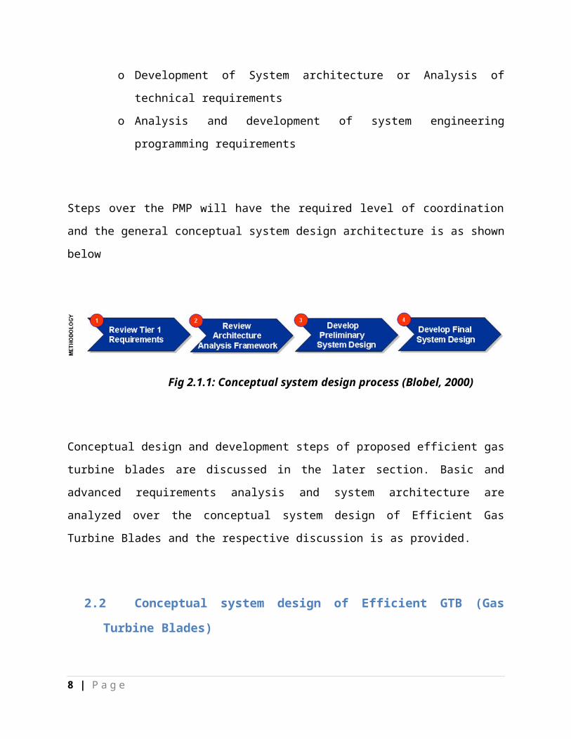
Fig 2.2.1: Thermodynamic cycle state analysis of Gas turbine (Li, 2014)
2. Once the thermodynamic cycle analysis is done against the TvsS requirements, the
respective pressure ratio will be calculated using the respective compressor efficiency
factor. Both the kinetic and potential energies are ignored at this stage and the
corresponding compressor work is estimated at the mass units.
3. With the calculated pressure ration the actual pressure drop is estimated over the
combustion chamber of the respective gas turbine. Always the required level of
efficiency can be achieved by selecting the maximum temperature that can be further
compatible with the corresponding material of the gas turbine blade or nozzle of the
turbine.
4. Both the pressure ratio and pressure drop over the turbine are used as the input to
calculate the respective gas turbine efficiency which is further processed against the
actual state or temperature of the gas
5. Heat recovery and noise abatement components are installed against the process of
pressure exist from the respective gas turbine. Power generated from the gas turbine and
the corresponding efficiency is estimated based on the overall heat produced from the
respective combustion chamber. Now the required thermal efficiency of the gas turbine is
calculated as a result from division of overall heat energy and the corresponding output
power.
All the five steps are analyzed against the requirements analysis and forms the basic framework
of the conceptual design of the proposed system i.e., gas turbine engine blade. Once the core
requirements analysis is done, preliminary design of the proposed system is developed and as
provided below
8 | P a g e
3. Preliminary system design of Gas Turbine blades
3.1 Overview of Preliminary design
Development definitions of the proposed system at the conceptual system design phase are done
across the preliminary design of the system. Based on the requirements analysis done over the
conceptual design phase are allocated and the further concepts of the proposed system and the
corresponding subsystems are developed at the preliminary system design phase of any project
development process. The main aim or purpose of preliminary system design is to demonstrate
the respective system with respective design and performance specifications.
All the available and possible methods against the system development are analyzed over the
preliminary design and a detailed schedule and cost constraint analysis is developed. Conceptual
design evolves the “what” analysis and “how” analysis with respective requirements gathering
and system development is done over the preliminary design stage. Lower level design
requirements are fetched against the proposed system “how” analysis, where the key
requirements like product development process and the respective material specifications are
analyzed over the preliminary design. Following are some of the important aspects covered over
the preliminary system design
9 | P a g e

System functional analysis
Allocation of the identified requirements
Studies with respective to trade off’s of the proposed system
Design alternative evaluation and analysis
Acquisition plans and early prototyping
Evaluation of supplier activities and major suppliers
Contracting and program implementation analysis (Rizzi, 2006)
A typical program and functional requirements documentation tree is developed at the
preliminary system design stage and is as provided below
Fig 3.1.1: Program or functional requirements documentation tree (Rizzi, 2006)
From the above program requirements documentation tree it is clear that there are many phases
at various units level and system engineering part level. Required preliminary design against
10 | P a g e

various stages is implemented based on the actual system design and the preliminary system
design of the proposed gas turbine cycle is as provided.
3.2 Preliminary design of proposed Gas turbine blade
Main goal of the preliminary design of a system and the important aspects covered across are
discussed in the previous section and the respective design principles are applied to the proposed
gas turbine in this section. The basic problem definition and the requirements are defined at the
conceptual design and the problem requirements it is clear that there are 5 important steps or
stages over developing the proposed efficient gas turbine cycles. From the aspect of preliminary
design, system functionalities and the development specifications are evaluated and provided as
below
3.2.1 System functionalities
Following are the key system functionalities of gas turbine
Design of HRSG (Heat Recovery System Generator) is done to extract the respective hot
gases from downstream boiler.
Exhausted hot gas is further processed by passing through steam turbine, where the
output from the turbine is combined with the output generated from the respective gas
turbine
Now the key function “bottoming cycle” of gas turbine is used to further process the
output and efficiency of the corresponding steam turbine.
11 | P a g e

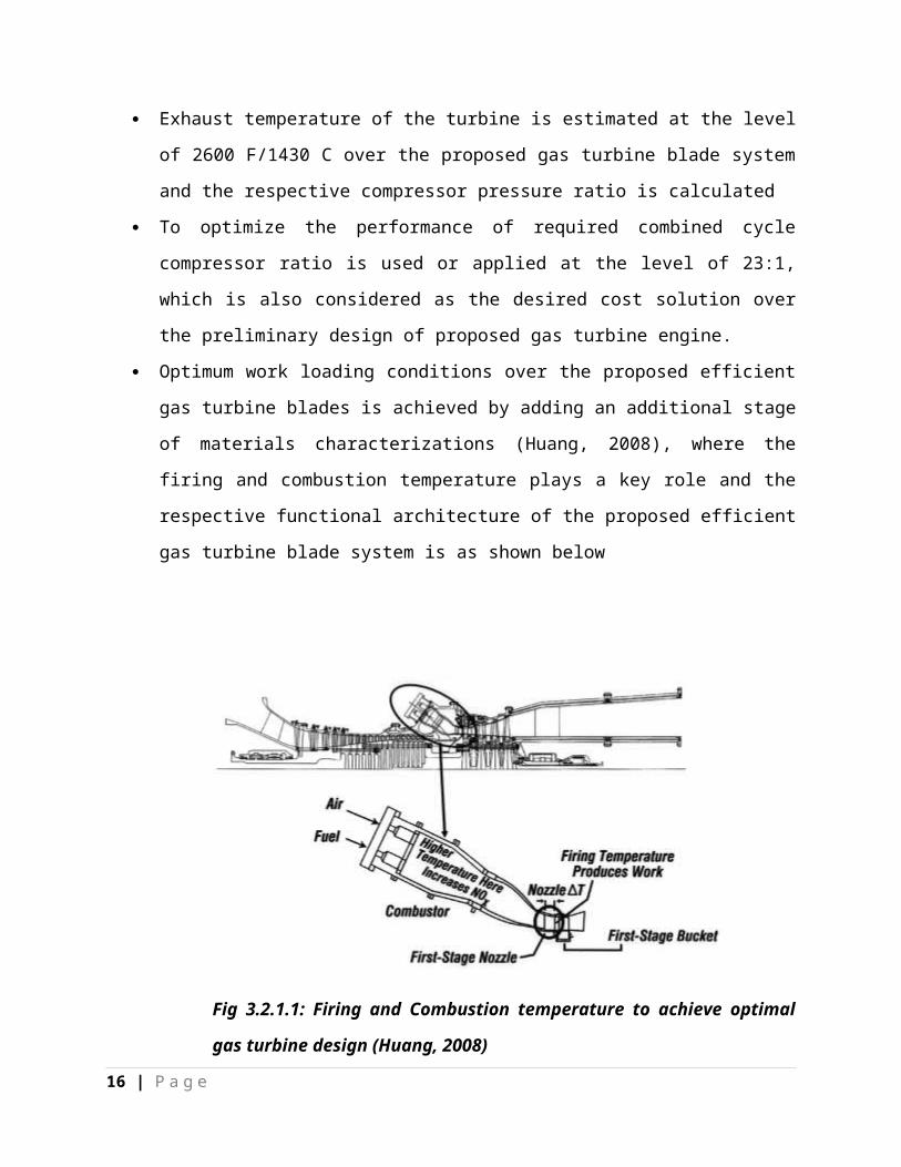
Exhaust temperature of the turbine is estimated at the level of 2600 F/1430 C over the
proposed gas turbine blade system and the respective compressor pressure ratio is
calculated
To optimize the performance of required combined cycle compressor ratio is used or
applied at the level of 23:1, which is also considered as the desired cost solution over the
preliminary design of proposed gas turbine engine.
Optimum work loading conditions over the proposed efficient gas turbine blades is
achieved by adding an additional stage of materials characterizations (Huang, 2008),
where the firing and combustion temperature plays a key role and the respective
functional architecture of the proposed efficient gas turbine blade system is as shown
below
Fig 3.2.1.1: Firing and Combustion temperature to achieve optimal gas turbine
design (Huang, 2008)
From the preliminary design analysis of the system, it is clear that, optimal combined cycle
system is required for the further detailed design of the efficient gas turbine system and is
discussed over the later sections.
12 | P a g e
4. Detailed design and development of Efficient Gas Turbine Blade
System
4.1 Overview of Detailed system design and development
Detailed system design is the continuation of the preliminary or iterative system development
process and a detailed evaluation of the system development is evaluated over the current system
design. Conceptual and preliminary design requirements of the proposed system are discussed in
the previous section and from the basic analysis the problem statement, system requirements and
system functional requirements are evaluated and the detailed system design and development
covers key aspects against the entire project development and they are as provided
Entire components of the system and the corresponding requirements are analyzed
All the design objectives are fulfilled by implementing the respective technical tasks
All the system elements, activities and components are integrated
Data requirements and design requirements are documented
Design aids and tools are utilized based on the selection made across the conceptual and
preliminary design stage
13 | P a g e

Prototype models are designed and developed against the basic system engineering s
requirements
Adopting the possible design changes, review, feedback and evaluation (Casper, 2001)
Detailed design and development process of a system can be mainly categorized as either
sequential or concurrent approaches and the respective block diagram is as shown below
Fig 4.1.1: Sequential and Concurrent approaches of system design (Casper,
2001)
14 | P a g e

4.2 Detailed design and development of Gas Turbine Blade System
Detailed system design and development of the proposed Gas turbine system includes the
analysis of the required components and the respective technical activities. Detailed design
principles of Jet propulsion are analyzed at this stage by integrating the H-technology towards
the development of combined cycle system development. Stage 1 nozzle cooling methods are
evaluated over the detailed system design, where the respective impact over the stage are shown
in the below architecture of Gas turbine blade cooling methods (Prencipe, 2000)
Fig 4.2.1: Impact of Stage 1 nozzle system design of Gas Turbine Blade System
(Prencipe, 2000)
Proposal of close loop cooling is made over the detailed design of the system, where there are
many benefits with the respective system development. Discharge air from the compressor will
be minimized at the parasitic extraction process and thus the overall efficiency of the proposed
Gas Turbine Blade System. Stem is used to replace the traditional chargeable air over the
proposed efficient Gas Turbine Blade system, where the overall performance system cycle is
enhanced with this detailed design approach. Following detailed system design and development
elements are covered across the design of proposed Gas Turbine Blade system
15 | P a g e
Design and development of required combustion chamber
Architecture level analysis of key factors that drive combustion process
Geometrically scaled 7H and 9H attributes are evaluated at the combustion chamber level
(Bailey, 2006)
Combustion chamber analysis is done using any of the modeling techniques like Ansys
and the respective snapshot is as provided
Fig 4.2.2: Mesh model of the proposed Combustion chamber of the Gas Turbine Blade design
(Bailey, 2006)
16 | P a g e

5. System test, evaluation and validation design of Gas Turbine Blade
system
5.1 Overview of System test, evaluation and validation design
In general the required system test, validation and evaluation design requirements are estimated
at the conceptual system design stage itself. Individual system elements and components are
considered over the system validation and test design level, where the respective system design
includes the key components like individual elements, subsystems and the corresponding
integrated subsystems. Configuration requirements and the proposed system are evaluated using
the system validation design, where all the processes and steps are considered in this context.
Identification of the basic system level requirements are done at the system evaluation design,
where these requirements are covered at operational level, development level, configuration
level, support and maintenance level (Avizienis, 2004). A general iterative approach is used at
the system test and evaluation design and the corresponding process is shown in the below flow
diagram
17 | P a g e
Fig 5.1.1: Flow diagram of system requirements and evaluation design
(Avizienis, 2004)
18 | P a g e

5.2 System test and validation design of proposed efficient Gas Turbine
Blade system
Proposed efficient Gas Turbine Blade system is evaluated at the conceptual, preliminary, detailed
design level and this sections deal with system test and validation requirements and they are as
listed below
Proposed system is tested at the total pressure and total temperature level and below are
the graphs showing the proposed performance of efficient Gas Turbine system
Fig 5.2.1 Total temperature and Pressure resulted over the proposed efficient Gas Turbine
blade system (Zelina, 2005)
Mass fraction and the respective radiation intensity of the proposed thermal efficient gas
turbine blade system are tested and validated and the resultant graphs are as shown below
19 | P a g e

Fig 5.2.2: Radiation intensity and mass fraction results of the proposed system design
(Zelina, 2005)
Thus the resultant graphs are used to test or validate the performance and efficiency of the
proposed Gas Turbine Blade system and rest of the tests over the proposed system design can be
discussed over the further research.
6. Conclusion
Current research aims at evaluation and investigation of various design methodologies and
aspects over a typical system development or system engineering process. Conceptual,
preliminary, detailed and system test and validation level system design approaches are
20 | P a g e

discussed in detailed over the current research. Design of an efficient Gas Turbine Blade system
is studied under the respective system design approaches and the required problem definition,
system requirements, system functional requirements, detailed design and development are
discussed and the resultant performance of the proposed system is validated and tested using the
performance graphs as shown in the previous section.
References
21 | P a g e

Avizienis, A, 2004, Basic concepts and taxonomy of dependable and secure computing,
Dependable and Secure Computing, IEEE Transactions on, Vol.1, no.1, p116-1234.
Bailey, D, 2006, Post-Combustion Decarbonisation Processes, Oil & Gas Science and
Technology, Vol.60, no.3, p110-116.
Blobel, B, 2000, Application of the component paradigm for analysis and design of
advanced health system architectures, International Journal of Medical Informatics,
Vol.60, no.3, p118-131.
Casper, G, 2001, New insights in computer-aided conceptual design, Design Studies,
Vol.16, no.1, p11-19.
Hewett, T, 2005, Informing the design of computer-based environments to support
creativity, International Journal of Human-Computer Studies, Vol.63, no.5, p16-23.
Hofmeister, C, 2007, A general model of software architecture design derived from five
industrial approaches, Journal of Systems and Software, Vol.80, no.1, p110-119.
Huang, Y, 2008, Techno-economic study of CO2 capture and storage in coal fired
oxygen fed entrained flow IGCC power plants, Fuel Processing Technology, Vol.89,
no.9, p16-23.
Krehl, P, 2009, General Survey, History of Shock Waves, Explosions and Impact, Vol.43,
no.6, p18-21.
Li, Y, 2014, Performance-analysis-based gas turbine diagnostics: A review, Propulsion
and Aerospace Engineering, Vol.3,no.1, p16-23.
Prencipe, A, 2000, Breadth and depth of technological capabilities in CoPS: the case of
the aircraft engine control system, Research Policy, Vol.7, no.2, p17-22.
Rizzi, S, 2006, Research in data warehouse modeling and design: dead or alive?, DOLAP
'06 Proceedings of the 9th ACM international workshop on Data warehousing and OLA ,
Vol.10, no.3, p12-16.
Wong, J, 2008, Evaluating the system intelligence of the intelligent building systems:
Part 1: Development of key intelligent indicators and conceptual analytical framework.
Automation in Construction , Vol.17, no.3, p19-24.
Zelina, J, 2005, Ultra-Compact Combustion Technology Using High Swirl
for Enhanced Burning ,38th AIAA/ASME/SAE/ASEE Joint Propulsion
Conference & Exhibit, Vol.32, no.6, p16-23.
22 | P a g e

#SystemDesignAssignmentHelp
#NetworkDesignAssignmentHelp
#CyberSecurityAssignment
#AssignmentHelp
#ManagementAssignmentHelp
#AssignmentsHelp
#ProjectsHelp
#HomeworkHelp
#DissertationsHelp
#ThesisHelp
#AcademicAvenue
#AcademicsHelp
#FrustratedWithAssignments
#MarketingAssignmentHelp
#ResearchProposalHelp
#CaseStudyHelp
#ResearchReportHelp
#SurveyHelp
23 | P a g e
Recommended