Screening and Qualification Testing of Chip Tantalum Capacitors for
Space Applications
Alexander Teverovsky
Dell Perot Systems
Code 562, NASA GSFC, Greenbelt, MD 20771
Abstract
In this work, the existing screening and qualification system for solid chip
tantalum capacitors manufactured per MIL-PRF-55365 have been analyzed,
and recommendations for improvements are discussed. A new test,
breakdown margin verification, is introduced, and a test flow for upscreening
and quality verification of commercial tantalum capacitors for space
applications is suggested.
Introduction
Tantalum capacitors manufactured per MIL-PRF-55365 are established reliability
components and parts used for space applications suppose to have failure rates of less than
100 FIT. Practice is seemingly confirming high reliability of chip tantalum capacitors;
however, this is mostly due to a severe derating employed by all manufactures of military
and space electronics. In spite of derating, although rarely, failures of tantalum capacitors do
happen, and several such failures occurred during ground-phase testing over the last few
years in the space industry. Due to the specifics of applications (typically in power supply
lines) and short-circuit failure mode with the possibility of ignition, each instance of such a
failure might cause catastrophic consequences for the system. This indicates the need for
analysis of possible deficiencies in the screening and qualification (S&Q) system currently
used to assure adequate reliability of tantalum capacitors for space applications.
In the most recent version of MIL-PRF-55365, released in March 2008, a new grade T of
capacitors was introduced. These capacitors are supposed to have the highest quality and are
recommended for space applications. Batches of grade T parts should be traceable down to
lots of tantalum powders, have Weibull failure rates equal to or better than 100 FIT, have
mandatory three-temperature surge current testing (SCT), destructive physical analysis
(DPA) and radiographic inspections, and have dielectric leakage currents (DCL) and
equivalent series resistances (ESR) within three standard deviations from the mean values.
These requirements provide tighter control over the production and offer a better traceability

of the lots. However, test conditions and requirements of the existing S&Q system were not
revised, and if currently used tests and procedures have deficiencies, these additional
measures might not assure the necessary improvement in the product’s quality.
It has been shown that failures of tantalum capacitors can be considered as time-dependent
dielectric breakdowns (TDDB) [1], and the time to failure is an exponential function of the
ratio between the operational voltage and breakdown voltage (VBR) of the Ta2O5 dielectric.
For this reason it is important that the S&Q system would be able to assure that a sufficient
margin between the rated voltage and breakdown voltages of the capacitors exists and
remains within the required limits after various environmental stresses.
In this work, analysis of MIL-PRF-55365 requirements is made based on data from relevant
literature and extensive testing of chip tantalum capacitors carried out under the NASA
Electronic Parts and Packaging (NEPP) Program over the last few years. Recommendations
for improving MIL-PRF-55365 procedures and suggestions for S&Q of commercial tantalum
capacitors for space applications are discussed.
Deficiencies of screening procedures per MIL-PRF-55365
Definitions of screening and qualification testing are not well established and a variety of
terms including quality assurance, qualification inspection, verification of qualification,
conformance inspection, periodic inspection, etc., are used in military documents. In this
work, for simplicity, we assume that testing performed on 100% of the parts to reduce the
probability of infant mortality failures are screening procedures, and all tests performed on a
sample basis to demonstrate the necessary level of long-term reliability of the parts under
environmental stresses are qualification procedures. These definitions correspond also to the
practice of S&Q of commercial parts for high-reliability applications.
Below, major screening test procedures, including measurements of the equivalent series
resistance, dielectric leakage current, surge current testing, and Weibull grading are
analyzed. Also, the necessity of a new test, safety margin verification, which has the purpose
of assuring that the breakdown voltages in the lot have a certain margin to the rated voltage,
is discussed.
ESR measurements.
ESR is a critical parameter of tantalum capacitors that affects directly the value of ripple
currents and power losses when capacitors are used for filtering in power supply lines [2].
This parameter is related mostly to the resistance of the manganese cathode layer, but
depends also on the graphite and silver epoxy coatings, and on the quality of silver epoxy
attachment to the cathode terminal. In spite of its importance, this parameter is not measured
after surge current testing.
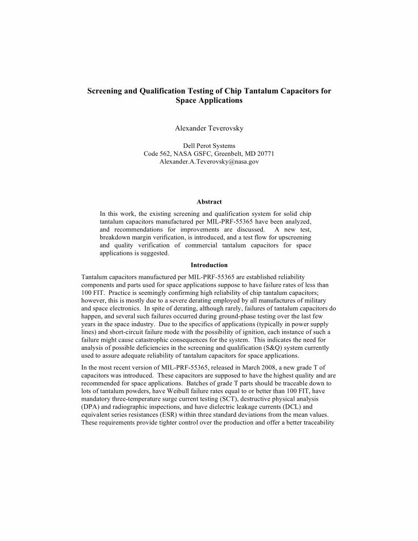
Our experiments showed that in some cases surge current testing (SCT) can degrade ESR in
tantalum capacitors. Figure 1 shows examples of variations of current spike amplitudes with
voltage during step stress surge current testing for 22 uF/15 V and 3.3 uF/10 V CWR06-style
capacitors. In both cases, a linear relationship between the current amplitude and voltage
that is typical for majority of the parts, changes after a certain voltage to a linear relationship
with a lower slope. This behavior indicates an increase in the effective resistance of the
circuit, which in turn indicates changes in ESR values [3]. This phenomenon is likely due to
development of delaminations and cracking in the cathode attachment caused by significant
mechanical stresses in the parts associated with the surge current testing.
Direct measurements of parts exhibiting anomalous variations of Isp(V) confirmed a
significant increase in the equivalent series resistance. Although the observed anomalies
occurred at voltages exceeding the rated voltage (VR), it shows that this test can potentially
cause degradation of ESR values even during regular SCT per MIL-PRF-55365.
Respectively, the post-SCT ESR measurements are necessary to assure that no internal
mechanical damage to the parts was introduced. Parts with significant variations of ESR
before and after SCT should be rejected.
2.2uF 15V
R=1.55 Ohm
R=2.99 Ohm
5
7
9
11
13
15
17
19
21
10 20 30 40 50
voltage, V
cu
rre
nt
sp
ike
, A
3.3uF 10V
R=0.49 Ohm
R=0.83 Ohm
0
10
20
30
40
50
60
70
0 10 20 30 40 50
voltage, V
cu
rre
nt sp
ike
, A
Figure 1. Variations of current spike amplitudes during step stress surge current testing of 2.2 uF/15 V
and 3.3 uF/10 V CWR06-style capacitors.
Analysis of ESR distributions was carried out for 14 lots of tantalum capacitors with 9 to 80
samples in each lot. In all cases, the normal function described experimental data
adequately. Using the 3-sigma criterion, a few failures (on average ~0.75%) were observed
for both military-grade and commercial products. Note that all ESR values, even those
outside the 3-sigma limits, were within the data sheet requirements. This confirms the
effectiveness of the 3-sigma criterion for selection of the best-quality parts.

Leakage current measurements.
Out of four electrical characteristics specified for tantalum capacitors (C, DF, ESR, and
DCL) leakage current is the one that is commonly assumed to be the most sensitive to the
presence of defects in Ta2O5 dielectric, and hence to be directly related to reliability of the
parts. A trend of decreasing of the time-to-failure for capacitors having greater DCL values
was observed during our highly accelerated life testing. This indicates the importance of
selecting parts with the lowest leakage currents for high-reliability applications. However,
the existing requirements for maximum acceptable DCL values are too loose and leakage
currents of the majority of the population in a lot are more than one to two orders of
magnitude lower than the specified values. Also, the test conditions as they are specified in
MIL-PRF-55365 might be not optimal to reveal and reject outliers (parts with excessive
DCL) in the lot.
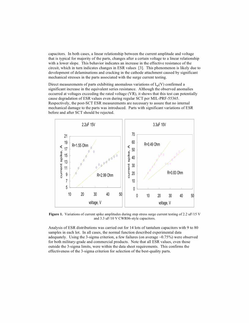
Leakage currents in tantalum capacitors are not constant, but vary with time after voltage
application, similar to I-t characteristics shown in Figure 2. Generally, these currents are a
sum of absorption currents that decrease with time, and leakage currents that do not vary
with time during measurements. Absorption currents are due to charging of electron traps in
the Ta2O5 dielectric; they do not depend on the presence of macro-defects, and their decay
can continue for several hours after voltage application. The leakage current is a sum of a
current related to the intrinsic conduction mechanisms in the Ta2O5 dielectric and a current
caused by the presence of macro-defects. The first, flows through the defect-free areas of the
dielectric and is controlled by the Poole-Frenkel and/or Schottky mechanisms of
conductivity. The second, defect-related current, in a simplified form can be considered as a
current flowing through a defective, thin area of the dielectric layer and/or at an asperity of
the electrode.
Due to the presence of high density of electron traps in anodic Ta2O5 dielectric, absorption
currents are high and often conceal the presence of the defects. To measure defect-related
currents in tantalum capacitors, the time under bias should be great enough. Note that
currents in 22 uF/15 V capacitors shown in Figure 2 are below the specified limit of 3.3 uA
already after 10 seconds, but two out of nine parts that have excessive leakage currents could
be revealed only after ~300 seconds.
MIL-PRF-55365 requirements for DCL measurements are confusing: “DC leakage shall be
measured … after a maximum electrification period of 5 minutes”. Because measured
currents decay with time, a manufacturer can stop taking readings as soon as it is below
DCLMAX. (for example, after 10 seconds for the 22 uF 15 V capacitors shown in Figure 2).
However, these measurements would not represent defect-related currents, and at these
conditions the presence of defective samples in the lot cannot be revealed. For this reason,
the specification for DCL measurements should explicitly specify that the reading should be
taken after 5 minutes of electrification minimum.
22uF 15V at 15V
1.E-09
1.E-08
1.E-07
1.E-06
1.E-05
10 100 1000 10000
time, sec
cu
rre
nt, A
22uF 15V at 20V
1.E-09
1.E-08
1.E-07
1.E-06
1.E-05
10 100 1000 10000
time, sec
cu
rre
nt,
A
a) b)
Figure 2. Decay of leakage currents in nine 22 uF/15 V capacitors with electrification time under rated
voltage (a) and at V = 1.33VR (b).
Due to the exponential dependence of leakage currents on both, temperature and voltage, the
sensitivity of measurements can be substantially enhanced by performing DCL test at high
temperatures and/or higher than rated voltages. Figure 2b shows that measurements at V =
1.33VR make the presence of defective parts in a lot much more apparent and at shorter
electrification times. Note that application of voltages exceeding VR is widely used during
S&Q procedures and is not damaging for normal-quality parts. For example, surge voltage
testing is performed at 85 oC and 1.3VR and up to 1.53VR is applied at 85
oC during Weibull
grading test.
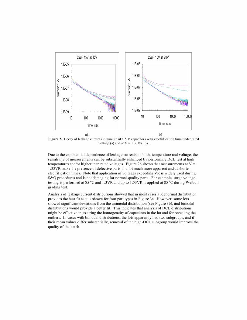
Analysis of leakage current distributions showed that in most cases a lognormal distribution
provides the best fit as it is shown for four part types in Figure 3a. However, some lots
showed significant deviations from the unimodal distribution (see Figure 3b), and bimodal
distributions would provide a better fit. This indicates that analysis of DCL distributions
might be effective in assuring the homogeneity of capacitors in the lot and for revealing the
outliers. In cases with bimodal distributions, the lots apparently had two subgroups, and if
their mean values differ substantially, removal of the high-DCL subgroup would improve the
quality of the batch.
Probability - Lognormal
leakage current, A
cumulative probability, %
1.E-10 1.E-51.E-9 1.E-8 1.E-7 1.E-61
5
10
50
99
22 uF/15 V
10 uF/25 V
15 uF/35 V
47 uF/20 V
Probability - Lognormal
leakage current, A
cumulative probability, %
1.E-9 1.E-41.E-8 1.E-7 1.E-6 1.E-51
5
10
50
99
3.3 uF/10 V
100 uF/10 V
100 uF/16 V
a) b)
Figure 3. Distributions of DCL for different part types showing good (a) and poor (b) approximation
with the lognormal functions.

Analysis shows that application of the 3-sigma rule that is based on an assumption of normal
distributions still allows for screening out some parts with the highest levels of leakage
currents. Using the 3-sigma criterion, the number of failures for each lot was calculated.
The proportion of failures averaged at 0.31% and varied from 0.33% to 0.67% for
commercial parts and from 0% to 0.5% for military-grade parts. A similar range of DCL
failures for military and commercial parts indicates that their quality might be not as different
as is usually assumed. This result is in agreement with the analysis of breakdown voltages in
military and commercial parts [4].
Note that generally application of the 3-sigma criterion does not remove all outliers. Figure
4 shows distributions for two virtual lots of capacitors with 23 and 33 samples. Leakage
currents for 20 and 30 samples were generated using log-normal distributions, and then three
parts with significantly larger currents were added to the lots to simulate outliers. In this
case, application of the 3-sigma criterion resulted in rejection of one part in the first lot and
two parts in another lot. However, two parts in the first lot and one in the second lot would
be considered acceptable. This example indicates a serious deficiency in the existing
requirements, and confirms the necessity of using adequate statistical analysis to reject
potentially defective parts in the lot.
Probability - Lognormal
current, A
cumulative probability, %
1.E-9 1.E-51.E-8 1.E-7 1.E-61
5
10
50
99simulation\M=-16, STD=0.4, 21Lognormal-2PRRX SRM MED FMF=23/S=0
Data PointsProbability Line
simulation\M=-18, STD=0.2, 21Lognormal-2PRRX SRM MED FMF=33/S=0
Data PointsProbability Line
Figure 4. Monte-Carlo simulation of lognormal distributions of leakage currents. Three introduced
outliers. Red circles indicate parts that would have been rejected and green circles denote samples that
would have been accepted based on the 3-sigma criterion.

Surge current testing (SCT).
Surge current testing is a stress test that have a purpose of assuring that no first turn-on
failures will occur in capacitors used in low-impedance circuits. This test per MIL-PRF-
55365 is performed at the rated voltage, and hence provides a zero safety margin for the
rated conditions. This is one of the reasons for which all manufacturers of chip tantalum
capacitors are warning users against using their parts at the rated voltages and suggest
derating. This situation is probably specific to tantalum capacitors only. Normally,
manufactures of high-reliability electronic components guarantee reliable application of their
products at the rated conditions, and derating is a means for a user to further increase
reliability of the parts during applications.
In addition to the absence of the safety margin, SCT has other deficiencies related to the test
conditions that have been discussed in [3, 5-6], and can be summarized as follows:
1. Results of SCT depend on the rate of voltage changes that is controlled by the value
of limiting resistors, inductance of the circuit (length of the connecting wires), and
the type of switches used. The most stressful conditions of testing can be achieved
by using no limiting resistors, short connecting wires, and power field-effect
transistors (FETs) as switches operating under sharp gate pulses. Measurement of
the current spike amplitudes allows for an estimation of the effective resistance in
the circuit, Rc, and should be used to control the correctness and reproducibility of
the test results. Acceptable test conditions can be determined as Rc ! 0.5 + ESR.
2. SCT failures at rated voltages can occur at any number of cycles, so the parts that
passed 10 cycles at VR, as is currently required per MIL-PRF-55365, have a certain
probability of failures after screening. To reduce this probability substantially, SCT
should be performed at 1.1VR. This would provide a 10% safety margin for surge
current events at the rated voltage.
Weibull grading test (Burn-In)
All high-reliability components are typically screened by a burn-in (BI) test to eliminate
marginal devices and reduce the probability of infant mortality failures. This test is
considered as a most critical procedure in the screening process and is typically performed at
or above maximum rated operating conditions (MIL-STD-883, TM 1015). As was shown in
[1] a specific of tantalum capacitors is that infant mortality failures continue with time of
operation till most of the parts in the group fail. For this reason, the purpose of BI for
tantalum capacitors should be a reduction of the failure rate below the acceptable level as it
performed during Weibull grading test.
Two BI procedures are known for tantalum capacitors: voltage aging and Weibull grading
test. Both tests are performed at 85 oC for 40 hours or more (for Weibull test). The voltage
aging test is carried out at the rated voltage and the Weibull grading test at voltages varying
from 1.1VR to 1.53 VR depending on the required level of reliability. Obviously, the
voltage aging test provides much less stress to the part and likely for this reason it was
replaced after 1990 with the Weibull grading test.
Calculations of the test conditions and reliability grading per MIL-PRF-55365 are based on
the validity of the expression for the voltage acceleration factor:
!!"
#$$%
&''=
(
RV
VAF 77249321.18exp1003412025.7
9
(1)
This formula was obtained by Navy Crane in the late 1970s for hermetically sealed solid
tantalum capacitors [7], and its applicability for contemporary chip tantalum capacitors is
questionable [8]. Our analysis [1] has shown that this equation might be valid at specific
conditions only. In particular, VR should be proportional to the breakdown voltage of the
capacitor. However, the coefficient of proportionality between VBR and VR varies from
manufacturer to manufacturer and from lot to lot, thus indicating that reliance on this
equation might produce erroneous results.
In spite of possible errors in calculating failure rates based on results of the Weibull grading
test, stressing of tantalum capacitors at high temperatures and voltages exceeding VR is
aligned with the philosophy of burning-in of high-reliability components and has been
proven to be effective. For this reason, BI testing at 85 oC and 1.5VR for 40 hours seems to
be a reasonable screening procedure for the space-grade capacitors.
Another problem with using the Weibull grading test is related to the method of detecting
failures. During the test, capacitors are connected to a power supply through 1A or 2A fuses
(or an equivalent electronic circuit) with cold resistance of not more than 1 Ohm. A failure is
defined as a blown fuse or equivalent, and the failed parts are removed from the lot. One
obvious problem with this test is that results of screening with 1 A fuses might be not
equivalent to the results of testing with 2 A fuses.
To blow a 1 A fuse, the part should either fail short circuit permanently, or experience a
current spike of more than a dozen amperes during a few milliseconds. Our experiments
show that parts that exhibit scintillations had higher probability of repeat scintillations and
failures and should not be acceptable even if their characteristics after testing remain within
the specification limits. An apparently anomalous recovery of capacitors after failures
during BI is often observed and can be explained assuming that scintillations that had caused
the fuse to blow open resulted in self-healing and did not destroy the part.
Using Weibull grade testing with 1 or 2 A fuses allows relatively low-current scintillations
(below few amperes) remain undetected. Such scintillations might damage the part and
degrade its reliability, but if the post-Weibull-grading leakage current is within the specified
limits, the degraded part would not be rejected. To screen-out these parts, the amplitude of
detectable current spikes should be reduced by at least an order of magnitude. For this, the
BI testing is recommended to be carried out using 125 mA fast acting fuses (or an equivalent
electronic circuit) with a cold resistance of 1 Ohm or less.
Margin verification test.
The rated voltage of tantalum capacitors is a major parameter of the part that is directly
related to its reliability. All models used to calculate acceleration factors of the test
conditions compared to the operation conditions, and respectively to predict reliability of
capacitors, employ a ratio between the operational voltage and VR.
The physical model of failures of tantalum capacitors under steady-state conditions employs
breakdown voltages rather than rated voltages, and the acceleration factors of the time-to-
failure depend on the ratio V/VBR [1]. Obviously, the rated voltage can be used to calculate
AF if it is a fixed portion of VBR only. However, experiments described in [9] showed that
the correlation between VBR and VR is poor. This might explain a significant difference in
AF suggested by different manufactures of tantalum capacitors to predict reliability of the
parts. At a 50% derating (V/VR = 0.5) the values of AF suggested by different manufacurers
vary by almost four orders of magnitude. Considering that materials and technological
processes employed by different vendors do not vary substantially, one of the major reasons
for these variations is likely the difference in the methodology of determining VR employed
by different vendors and the lack of control over the breakdown voltages.
Analysis show that 50% minimum is a reasonable requirement for the margin that is
determined as M = (V1-VR)/VR*100, where V1 is the 1 percentile voltage of the distribution
of VBR. The margin verification test should assure that all parts in the lot have a minimum
of a 50% margin between the scintillation breakdown voltages and the rated voltage. This
test is similar to the constant charge current scintillation breakdown test, but the maximum
voltage is limited to 1.5*VR. The charging current during the test, Ich, is calculated based on
the requirement that the maximum voltage is to be reached in 10 ±2 seconds: Ich =
1.5!C!VR/10. The test is carried out at room temperature and only capacitors that did not
have scintillations below 1.5VR shall be considered as acceptable.
Deficiencies of qualification testing per MIL-PRF-55365
Temperature cycling, humidity, and life testing are major reliability qualification tests
commonly used for all high-reliability electronic components encapsulated in plastics.
Soldering onto a board is one of the most stressful events that all SMT components,
including tantalum capacitors, experience before applications, and this stress might affect
results of qualification tests substantially. For this reason, the effect of soldering is
considered below along with analysis of environmental and life testing.
Effect of soldering
Various environmental tests are normally used to demonstrate that the part has sufficient
margins to withstand stresses during typical application conditions. This is especially
important for surface mount technology (SMT) parts, in particular chip tantalum capacitors,
that experience environmental stresses always in combination with the soldering-induced
thermal shock [4, 10]. This thermal shock might impair tantalum pentoxide dielectric or
damage the attachment and thus accelerate degradation of the part under environment-
induced stresses. Therefore, to get an adequate assessment of quality and reliability of
tantalum capacitors, simulation of soldering stresses should be used as preconditioning
before qualification testing of the parts.
MIL-PRF-55365 addresses the effect of soldering twice, the first time during screening by
implementing reflow conditioning, and the second time during the resistance-to-soldering
heat test employed as qualification testing. During the reflow conditioning test all parts are
exposed one time to 230 oC for 5 seconds, but post-conditioning measurements are not
required. During the resistance-to-soldering-heat test, 18 capacitors are exposed one time to
235 oC for 30 seconds. One failure during the post-soldering-heat test electrical
measurements is considered acceptable if no failures have occurred during groups I and III
tests. Note that only C, DF, and DCL are measured after testing and ESR measurements are
not required, so possible degradation in anode or cathode attachment might remain
unnoticed. Potentially up to 5% of parts might fail after soldering, but the lot would be still
considered acceptable.
Flux application and three cycles of solder reflow simulation are required during
qualification testing per MIL-STD-202, TM210 to evaluate robustness of the parts to the
soldering-induced stresses. Relaxing these requirements to one cycle only might not reveal
potential problems with the lot, and does not reflect assembly conditions for a large group of
applications when parts are used on double-sided boards, thus experiencing solder reflow
stress two times. Our test results showed that normal-quality lots can withstand much more
than three solder reflow cycles without any degradation of breakdown voltages, DCL, and
AC characteristics.
The solder reflow stress might affect reliability of the parts under high-humidity
environments, during temperature cycling and operating life, and should be used as a
preconditioning for all reliability qualification tests. This would also mimic the real-life
situation in which parts before applications are soldered onto printed wiring boards (PWBs).
It has been shown that the pop-corning effect might occur in chip tantalum capacitors similar
to plastic encapsulated microcircuits (PEM) [11]. For this reason preconditioning of
tantalum capacitors should be carried out in a manner similar to PEMs, and it should include
moisture soaking (168 hours, 85 oC, 60%RH); flux application and cleaning; and three
reflow simulation cycles per MIL-STD-202 TM210 condition “J”. Post-reflow-simulation
electrical tests should include measurements of C, DF, DCL, ESR, surge current and margin
verification testing. This test should be performed on all space-grade parts intended for
qualification testing, and no failures should be allowed.
Effect of temperature cycling.
Tantalum capacitors manufactured according to MIL-PRF-55365 are subjected to five
thermal shocks (TS) between -55 °C and +125
°C (unmounted parts) during screening and to
10 TS (mounted parts) during qualification inspection. This means that the existing S&Q
system does not guarantee that tantalum capacitors can withstand multiple cycling, even
within a relatively narrow operating temperature range.

Contrary to tantalum capacitors, military-grade chip ceramic capacitors manufactured per
MIL-PRF-123 and microcircuits manufactured per MIL-PRF-38535 have much more
stringent requirements for temperature cycling (TC) or TS testing. Ceramic capacitors
should demonstrate capability to withstand 100 TS between -55 °C and +125
°C, and the
microcircuits during qualification testing are stressed with 100 TC between -65 °C and +150
°C.
Our tests have demonstrated that normal-quality lots of tantalum chip capacitors are capable
of withstanding 100 TC between -65 °C and +150
°C in loose condition. This justifies the
requirement for high-quality parts to demonstrate the capability to survive the F-3 test
conditions per MIL-STD-202 (100 TS between -65 oC and +150
oC). This would also allow
using such capacitors in MIL-PRF-38534 hybrid microcircuits without re-screening and re-
qualification.
Note that contrary to ceramic capacitors, in which mechanical stresses change substantially
after being soldered onto a board, in tantalum capacitors, due to the presence of some stress
relief provided by terminals, the stresses developed during TS might not vary substantially
for loose and soldered parts. This makes TS testing of loose tantalum capacitors more
effective and important compared to ceramic parts.
Effect of humidity.
Military specification MIL-PRF-55365 requires moisture resistance testing in accordance
with test method 106 of MIL-STD-202. According to this method the parts are subjected to
twenty 24-hour cycles in a humidity chamber without bias. During each of the cycles the
relative humidity and temperature varies several times from 80% to 100% RH at 25 oC to
90% to 100% RH at 65 oC. Note that at 100% RH moisture condensation is difficult to
avoid, so it is quite possible that some parts are immersed into water during this testing.
The purpose of the test per MIL-STD-202 is to evaluate the resistance of parts to
deteriorative effects of high-humidity and heat conditions typical in tropical environments
where direct surface wetting of metals and insulation might happen. It is assumed that this
test is especially effective due to employment of temperature cycling, which provides
alternate periods of condensation and drying essential to the development of the corrosion
processes.
Obviously, these test conditions are not adequate for capacitors used for space applications
where parts can be exposed to moisture during ground-phase testing and integration periods
only, and typically humidity of the environment does not exceed 85%. For this reason, a
commonly used 85 oC/ 85% RH test condition for 240 hours should be sufficient to assure
the necessary moisture resistance of the parts. Our experiments described in [12] showed
that most of the lots can withstand this testing without degradation. Note also that many
commercial tantalum capacitors, in particular used in the automobile industry, are subjected
to 85 oC/85% RH test for 1,000 hours under bias during qualification testing.

According to the existing requirements, after the testing C, DCL, DF, and ESR (when
specified) are measured. Variations of the capacitance after the test shall not exceed ±15%
of the initially measured values, and DCL changes should not exceed 200% of the rated
value. However, our experiments showed that changes of C depend on the previous history
of exposure of the parts to high humidity or dry conditions; and are likely due to the presence
of microvoids at the manganese/Ta2O5 interface [12]. Changes of the capacitance after
testing might vary depending on the initial condition of the parts, and in most cases these
changes are not related to moisture-induced degradation and do not indicate poor reliability
of the parts. On the other hand, our experiments show that in some cases parts after humidity
testing have excessive currents when measured at low voltages (1.5V), and these failures are
cleared later during measurements at rated voltages. It is possible that this effect is similar to
the low-voltage failure phenomenon well known for ceramic parts. For this reason,
measurements of DCL, at low voltages (1.5V), as well as margin verification tests, should be
added as post-humidity test procedures to reveal lots that degrade under humid
environments.
Life testing.
According to MIL-PRF-55365, life testing is performed for 2000 hours either at 85 oC and V
= VR, or at 125 oC and V = 0.67VR. In the first case, 102 parts are used with one failure
allowed. In the second case, 24 parts are used and also, one failure is allowed. It is assumed
that both test conditions are equivalent. Calculations of the voltage acceleration factor per
Eq. (1) for these conditions yield AF= 0.002. Assuming that the temperature-related
acceleration factor follows Arrhenius law, the corresponding activation energy should be 1.9
eV. This is a relatively large value, and estimations made based on the guidelines offered by
different manufacturers indicate much lower values of Ea, in a range from 0.2 eV to 1.2 eV.
This indicates that the equivalency of the two test conditions is doubtful and likely explains
several cases in which employment of both tests showed different results.
Life testing at 85 oC is performed at the same temperature as the Weibull grading test, thus
allowing for comparison of the test results. Assuming that one out of 102 parts failed life
testing, the failure rate at 85 oC at confidence level of 60% can be calculated as follows:
( ) ( )[ ] ( ) ( )[ ]hr
tNAF
nlcC
1000/%1108.92000102
1
2
4,6.0111
2
22,..1 622
85 !"="
"#
="
""+#
= #$$% ,
(2)
where !2 is the chi-square function, c.l. is the confidence level, n is the number of failures, N
is the number of samples, and t is the duration of the test; AF = 1 because the test is
performed within the operational conditions of the part.
Considering that the T-grade parts after Weibull testing have a failure rate of below 0.01%
per 1,000 hours, performing life test to confirm the level of reliability that is two orders of
magnitude larger (!85 = 1%/1000 1/hr) seems unreasonable. Obviously, the life-test
conditions are not stressful enough to demonstrate long-term reliability of tantalum
capacitors produced to level T. Note for comparison, that according to MIL-PRF-123 life
tests for MLCCs are performed using much more stressful conditions: two times rated
voltage, 125 oC for 1000 hours.
Assuming that a typical operational temperature of the part is 55 oC and “standard” activation
energy Ea = 0.7 eV, the 2000-hour life test at 85 oC would be equivalent to 1.8 years of
operation only. By raising the test temperature to 105 oC, the equivalent operational time
would increase to 6 years. Further increase of the stress level by raising voltage to 1.1VR
would raise the equivalent time to 36 years. Considering that the expected life of high
reliability parts is 10 to 20 years, it seems reasonable to require life testing to be performed at
105 oC, 1.1VR for 2000 hours. DCL measurements should be taken after 1hr, 500hr, 1000hr,
and 2000 hours of testing.
A substantial, up to three orders of magnitude, increase in leakage currents are observed
during life testing of tantalum capacitors [13]. According to our results (to be published)
this degradation is due to the presence of movable ionic charges, Qs, most likely oxygen
vacancies, and the level of current degradation, n, depends on the concentration and mobility
of the charges:
!!
"
#
$$
%
&
''
(
)
**
+
,'(
)*+
,-''
(
)**+
,+==
5.05.0
00
max expd
VQ
d
V
kTJ
Jn ss
..
/
,
(3)
where Jmax and J0, are the post-life test and initial currents corresponding to a condition when
all charges are accumulated at the anode interface, k is the Boltzmann constant, T is the
absolute temperature; "0 is the permittivity of the free space, and " #5 is the high-frequency
dielectric constant for Ta2O5, "s is the Schottky constant, V is the applied voltage, and d is
the thickness of Ta2O5 film.
Excessive charge, and respectively, excessive current degradation might indicate a higher
risk of failures under steady-state operating conditions, and should be limited. More data and
analysis are necessary to determine a reasonable limit for the acceptable level of current
degradation.
Recommendations for screening and qualification of commercial tantalum capacitors
The quality assurance system commonly used in military specifications is based on a detailed
and verifiable control of all process steps, traceability of materials used, and thorough
examination and testing during manufacturing. The S&Q procedures described in military
specifications present a sophisticated system of time-related (periodical), lot-related, and
sample-related tests designed to assure consistency in the quality of the product. Those
procedures have a proven record of successful use for mature products that are manufactured
in large quantities and for a long period of time. However, military-grade products have an
increased cost and, what is often more important for space projects, longer delivery time.

Also, these procedures cannot be adjusted easily for advanced technology, high-performance
commercial-off-the-shelf (COTS) products that are coming to the market with an increasing
speed.
Typically, space projects use a relatively small number of samples that are purchased for a
specific project only, and they require fast delivery. In these cases there is a need for
screening and qualification procedures that are capable of assuring the necessary quality and
reliability for a specific, small-sized lots of commercial tantalum capacitors. Considering
that materials and manufacturing processes used for military-grade and commercial parts are
similar, and the difference in their manufacturing is mostly related to the level of testing, it
seems that by employing a proper S&Q system for commercial parts, the quality required for
space applications can be realized. Additional confidence in reliability of commercial
product can be achieved by applying more severe derating requirements compared to
military-grade parts.
Screening test flow.
Based on the discussions above, the table below displays a suggested screening test flow for
commercial chip tantalum capacitors. It is based on the current MIL-PRF-55365
requirements with some variations described in the comments column. This test flow is
applicable to level 1 projects per GSFC EEE-INST-002 classification. For level 2 projects
SCT can be performed at room temperature only. For level 3 projects, the radiographic
inspection and margin-verification testing can be omitted, and stability at low and high
temperature test can be replaced with electrical measurements of C, DF, ESR, and DCL at
room temperature only.

Table 1. Screening process for commercial solid tantalum capacitors.
Test Method Comments
Visual inspection MIL-PRF-55365 Reflow conditioning MIL-PRF-55365 Thermal shock MIL-PRF-55365
Electrical measurements MIL-PRF-55365
Measurements of C, DF, ESR, and DCL. ESR
measurements are mandatory. DCL is measured at
1.3VR after 5 min electrification minimum.
Analysis of DCL and ESR distributions to assure
homogeneity of the lot and screen-out outliers.
Margin verification GSFC test method The test verifies that VBR_scint exceeds 1.5VR.
Radiographic inspection MIL-PRF-55365
Burn-in (voltage aging) MIL-PRF-55365
Except for V=1.5VR, resistance of the circuit does
not exceed 1 Ohm and failures are determined
using 125 mA fast acting fuses.
Surge current test
MIL-PRF-55365, conditions
A and B (three temperature
measurements)
Except for V = 1.1VR and effective resistance is
below 0.5 Ohm + ESR.
Stability at low and high temp. MIL-PRF-55365 ESR measurements are mandatory; DCL is
measured at 1.3VR.
Analysis of test results GSFC test method Analysis of C, DF, ESR, and DCL distributions.
Proportion of electrical, BI, and SCT failures.
Visual inspection MIL-PRF-55365
Note that log-normal function provides the best fit for distributions of DCL, and analysis of
these distributions, as well as distributions of breakdown voltages, can be used to assure the
homogeneity of the lot. This homogeneity analysis might be useful for selection of tantalum
capacitors for level 2+ projects.
Qualification test flow.
Analysis of drawbacks of MIL-PRF-55365 showed that one of the problems is related to the
absence of preconditioning and soldering simulation prior to reliability testing. Also, major
environmental tests including temperature cycling, moisture resistance, and life testing are
not stressful enough to assure long-term reliability of the parts. Space-qualified lots of
tantalum capacitors should demonstrate not only stability of their standard characteristics (C,
DF, ESR, and DCL) during post-stress-testing measurements, but also their breakdown
safety margins should remain within the specified limits.
A suggested qualification test flow for commercial tantalum capacitors is presented in Figure
5. A group of 50 samples is selected after screening for this testing. If results of screening
testing are available, no initial measurements are required. After preconditioning that
consists of moisture soak, flux application, and three solder reflow simulation cycles (per

JESD22-A113/MIL-STD-202, TM210), all parts are electrically tested including
measurements of C, DF, ESR, and DCL at rated voltage, SCT, and margin verification.
Then the parts are split in three subgroups for life testing (20 samples), temperature cycling
(15 samples), and humidity test (15 samples). Conditions of these stress tests are discussed
above. Post-stress testing measurements are performed as shown in Figure 5. No failures
are allowed. Note, that the duration of life testing can be reduced to 1000 hours by
increasing the stress (V, T) during testing. The possibility of application of highly
accelerated stress testing to tantalum capacitors is currently under investigation.
Figure 5. A simplified test flow for reliability qualification testing of chip tantalum capacitors. The
numbers in brackets show the minimum required quantity of samples.
Figure 5 shows a typical test flow for level 2 projects. For level 1 projects, life testing should
be performed during 2,000 hours; SCT is also required after humidity test, and the number of
temperature cycles might be increased based on the specific requirements of the project.
Summary
1. Deficiencies of MIL-PRF-55365 have been analyzed, and recommendations to change
screening and qualification procedures have been discussed.
2. Recommendations for screening can be summarized as follows:
2.1. ESR measurements should be used after SCT. Measurements of ESR during
screening and qualification testing should be mandatory, instead of “when
specified only.”
2.2. To reveal defects in the Ta2O5 dielectric, DCL measurements should be made after
five minutes of electrification minimum, not maximum as is required currently.
The effectiveness of revealing defects can be increased substantially if
measurements are made at 1.33 VR and 85 oC.
2.3. To prevent post-SCT failures during applications, this testing should be performed
at 1.1 VR using setups with the effective resistance of the circuit not exceeding 0.5
Ohm + ESR.

2.4. Employment of 1 A to 2 A fuses during the Weibull grading test allows detection
of capacitors that are permanently short, or have high-current scintillation spikes
(dozens of amperes) only. To reveal potentially defective capacitors with
relatively low current spikes, burn-in testing should be performed using 125 mA
fast-acting fuses with a cold resistance of not more than 1 Ohm or equivalent
electronic circuit. The suggested burn-in test conditions are: T = 85 oC, V = 1.5
VR, and t = 40 hours.
2.5. A margin verification test should be used during screening to assure that a 50%
minimum safety margin exists between the rated voltage and scintillation
breakdown voltages of capacitors in the lot.
3. Recommendations for reliability qualification testing:
3.1. Preconditioning, including moisture soak, flux application, and three solder reflow
simulations cycles, should be used prior to any reliability qualification testing of
the parts. Post-solder-reflow simulation testing should include SCT and margin
verification tests.
3.2. High-quality tantalum capacitors should demonstrate the capability to withstand
100 thermal shocks between -65 oC and +150
oC. Post-TS surge current and
scintillation breakdown margin verification tests should be used to verify quality of
the parts.
3.3. Space-grade parts should be able to pass a 10-day unbiased humidity test at 85 oC/85% RH without significant degradation of surge current and scintillation
breakdown voltages. Prior to DCL measurements at VR, leakage currents at 1.5 V
should be measured to assure that no low-voltage degradation occurred.
3.4. The existing life test conditions (85 oC, VR, 2,000 hours) are not stressful enough
to evaluate long-term reliability of the space-grade capacitors that are supposed to
have a failure rate of less than 100 FIT. The suggested life test conditions are
2,000 hours at 105 oC and 1.1VR.
4. Test flows recommended for screening and reliability qualification of commercial
tantalum capacitors for space applications are shown in the Table 1 and Figure 5.
Acknowledgment
This work was sponsored by the NASA Electronic Parts and Packaging (NEPP) Program.
The author is thankful to the Program Managers, Michael Sampson and Ken LaBel, for their
support and encouragement.
References
[1] A. Teverovsky, "Scintillation Breakdowns and Reliability of Solid Tantalum
Capacitors," IEEE Transactions on device and materials reliability, vol. 9, pp. 318-
324, 2009.
[2] E. K. Reed, "Tantalum chip capacitor reliability in high surge and ripple current
applications," presented at 44th. Electronic Components and Technology
Conference, 1994.

[3] A. Teverovsky, "Effect of Surge Current Testing on Reliability of Solid Tantalum
Capacitors," presented at The 28th Symposium for Passive Components,
CARTS'08, Newport Beach, CA, 2008.
[4] A. Teverovsky, "Effect of Environmental Stresses on Breakdown Voltages in Chip
Tantalum Capacitor.," presented at The 28th Symposium for Passive Components,
CARTS'09, Jacksonwille, FL, 2008.
[5] A. Teverovsky, "Effect of Inductance and Requirements for Surge Current Testing
of Tantalum Capacitors," presented at CARTS'06, the 26th Symposium for Passive
Components, Orlando, FL, 2006.
[6] E. K. Reed and J. L. Paulsen, "Impact of circuit resistance on the breakdown voltage
of tantalum chip capacitors," presented at CARTS, 2001.
[7] J. N. Burkhart, "Use of accelerated testing techniques in military specification MIL-
C--39003," presented at CARTS, Phoenix, AZ, 1983.
[8] J. L. Paulsen, E. K. Reed, and J. N. Kelly, "Reliability of Tantalum Polymer
Capacitors," presented at CARTS 2004: 24th Annual Capacitor and Resistor
Technology Symposium, 2004.
[9] A. Teverovsky, "Scintillation and Surge Current Breakdown Voltages in Solid
Tantalum Capacitors," IEEE Transactions on Dielectrics and Electrical Insulation,
vol. 16, pp. 1134-1142, 2009.
[10] R. Hahn, J. Piller, and P. Lessner, "Improved SMT Performance of Tantalum
Conductive Polymer Capacitors with Very Low ESR," presented at The 26th
symposium for passive components, CARTS'06, Orlando, FL, 2006.
[11] A. Teverovsky, "Effect of Temperature Cycling and Exposure to Extreme
Temperatures on Reliability of Solid Tantalum Capacitors," presented at
CARTS'07, the 27th Symposium for Passive Components, Albuquerque, NM,
2007.
[12] A. Teverovsky, "Effect of Moisture on Characteristics of Surface Mount Solid
Tantalum Capacitors," presented at CARTS'03, 23rd Capacitor and Resistor
Technology Symposium, Scottsdale, Arizona, 2003.
[13] T. Zednicek, J. Sikula, and H. Leibovitz, "A Study of Field Crystallization in
Tantalum Capacitors and its effect on DCL and Reliability," in 29th symposium for
passive components, CARTS'09. Jacksonville, FL, 2009, pp. 5.3.1-11.
Recommended