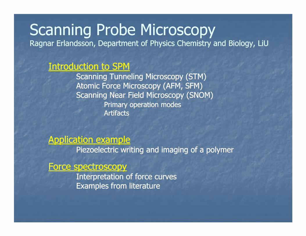
Scanning Probe MicroscopyScanning Probe MicroscopyRagnar Erlandsson, Department of Physics Chemistry and Biology, Ragnar Erlandsson, Department of Physics Chemistry and Biology, LiULiU
Introduction to SPMIntroduction to SPMScanning Tunneling Microscopy (STM)Scanning Tunneling Microscopy (STM)Atomic Force Microscopy (AFM, SFM)Atomic Force Microscopy (AFM, SFM)Scanning Near Field Microscopy (SNOM)Scanning Near Field Microscopy (SNOM)
Primary operation modesPrimary operation modesArtifactsArtifacts
Application exampleApplication examplePiezoelectric writing and imaging of a polymerPiezoelectric writing and imaging of a polymer
Force spectroscopyForce spectroscopyInterpretation of force curvesInterpretation of force curvesExamples from literatureExamples from literature
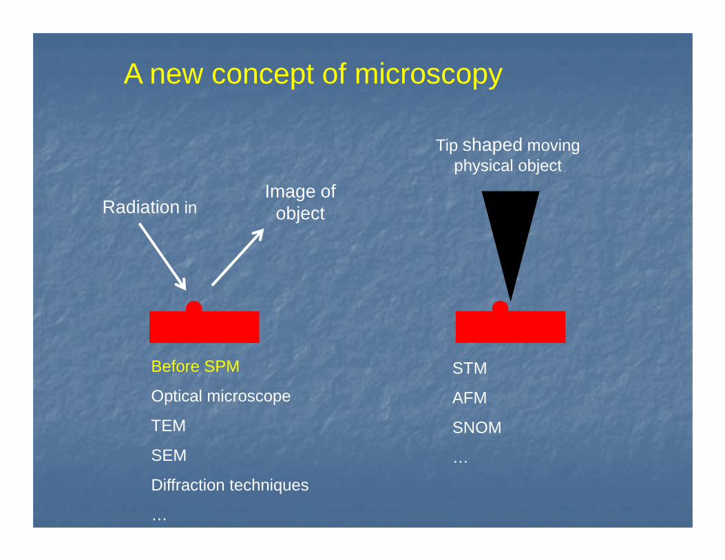
Radiation inImage of
object
Tip shaped moving physical object
A new concept of microscopy
Before SPM
Optical microscope
TEM
SEM
Diffraction techniques
…
STM
AFM
SNOM
…
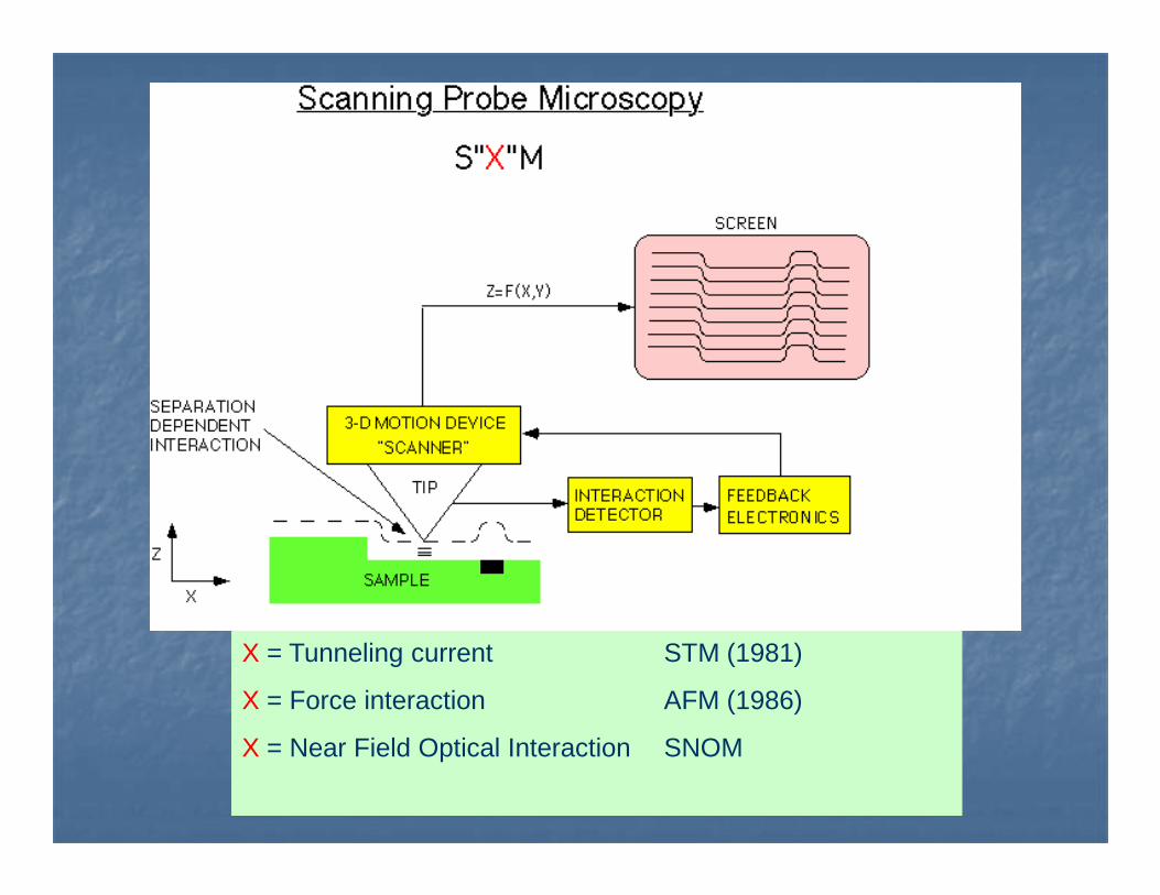
X = Tunneling current STM (1981)
X = Force interaction AFM (1986)
X = Near Field Optical Interaction SNOM
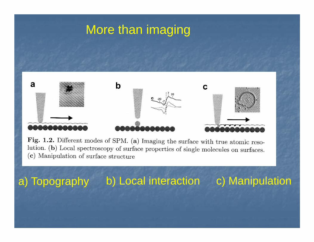
More than imaging
a) Topography b) Local interaction c) Manipulation
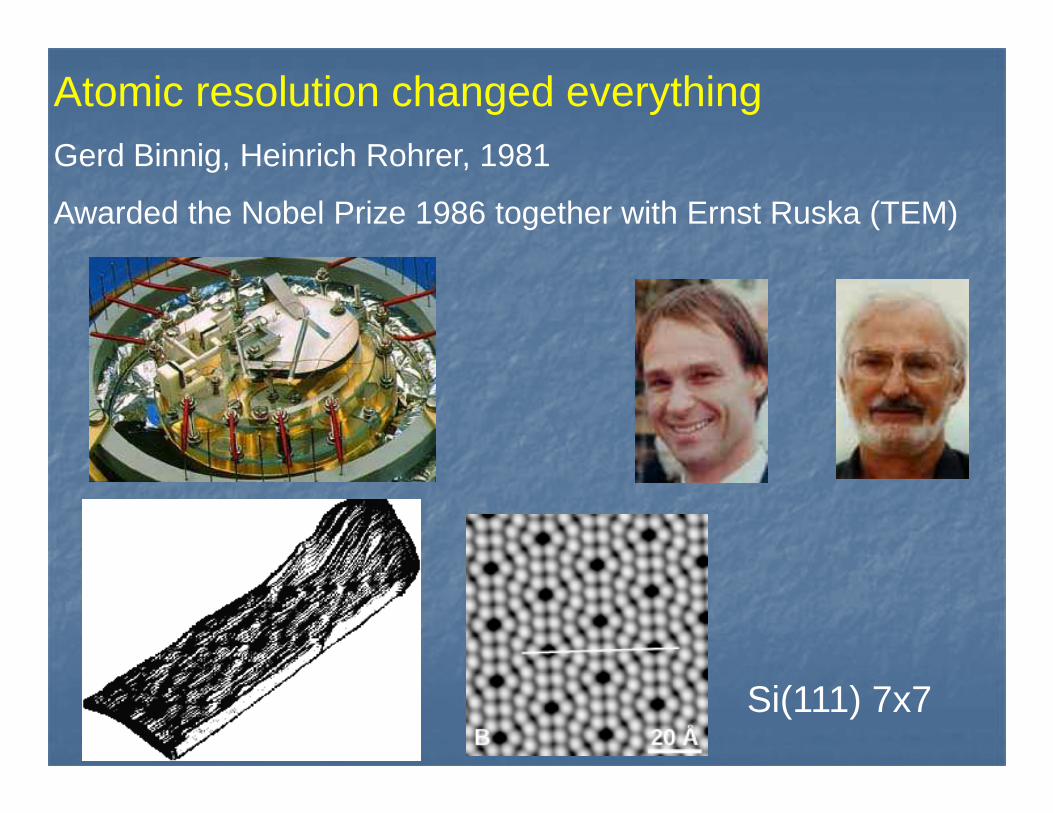
Atomic resolution changed everythingGerd Binnig, Heinrich Rohrer, 1981
Awarded the Nobel Prize 1986 together with Ernst Ruska (TEM)
Si(111) 7x7
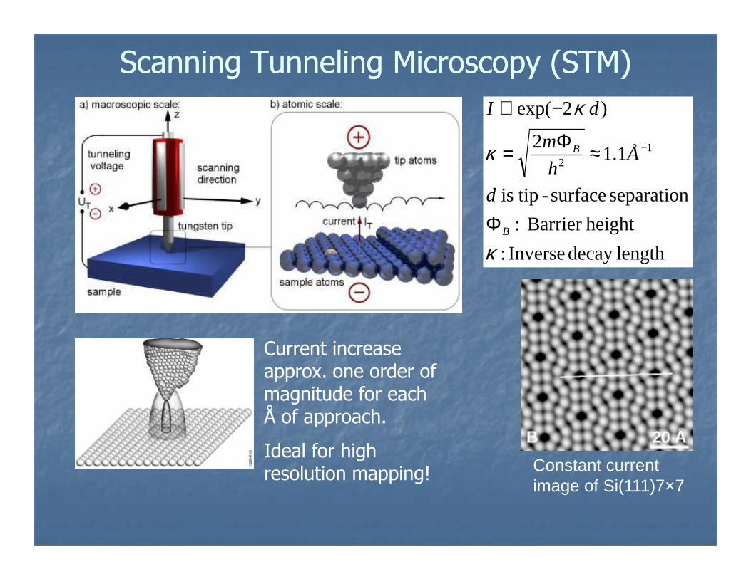
Scanning Tunneling Microscopy (STM)Scanning Tunneling Microscopy (STM)
lengthdecay Inverse :
heightBarrier :
separation surface- tipis
1.12
)2exp(
12
κ
κ
κ
B
B
d
Åh
m
dI
Φ
≈Φ=
−∝
−
Constant current image of Si(111)7×7
Current increase approx. one order of magnitude for each Å of approach.
Ideal for high resolution mapping!
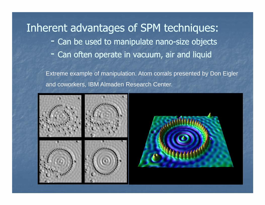
Inherent advantages of SPM techniques:Inherent advantages of SPM techniques:-- Can be used to manipulate nanoCan be used to manipulate nano--size objectssize objects
-- Can often operate in vacuum, air and liquidCan often operate in vacuum, air and liquid
Extreme example of manipulation. Atom corrals presented by Don Eigler
and coworkers, IBM Almaden Research Center.
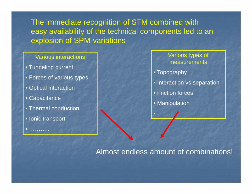
The immediate recognition of STM combined with easy availability of the technical components led to an explosion of SPM-variations
Various interactions
• Tunneling current
• Forces of various types
• Optical interaction
• Capacitance
Various types of measurements
• Topography
• Interaction vs separation
• Friction forces• Capacitance
• Thermal conduction
• Ionic transport
• ………..
• Manipulation
• …………
Almost endless amount of combinations!
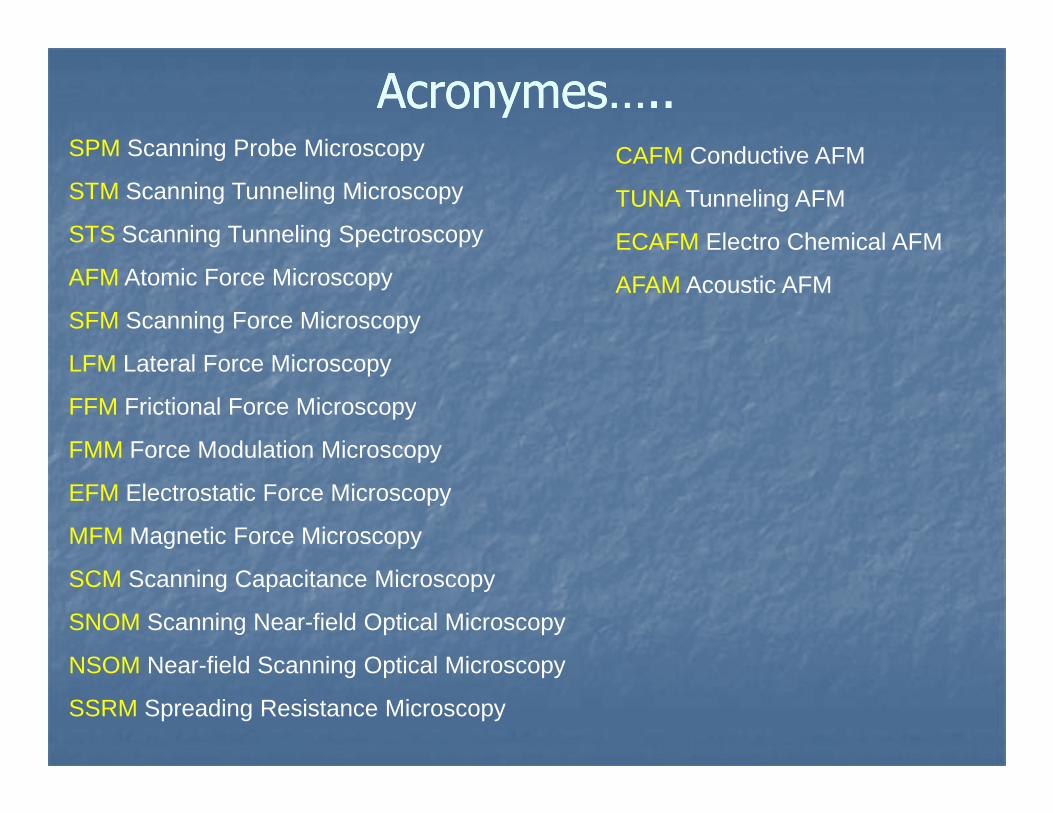
Acronymes…..Acronymes…..SPM Scanning Probe Microscopy
STM Scanning Tunneling Microscopy
STS Scanning Tunneling Spectroscopy
AFM Atomic Force Microscopy
SFM Scanning Force Microscopy
LFM Lateral Force Microscopy
FFM Frictional Force Microscopy
CAFM Conductive AFM
TUNA Tunneling AFM
ECAFM Electro Chemical AFM
AFAM Acoustic AFM
FFM Frictional Force Microscopy
FMM Force Modulation Microscopy
EFM Electrostatic Force Microscopy
MFM Magnetic Force Microscopy
SCM Scanning Capacitance Microscopy
SNOM Scanning Near-field Optical Microscopy
NSOM Near-field Scanning Optical Microscopy
SSRM Spreading Resistance Microscopy
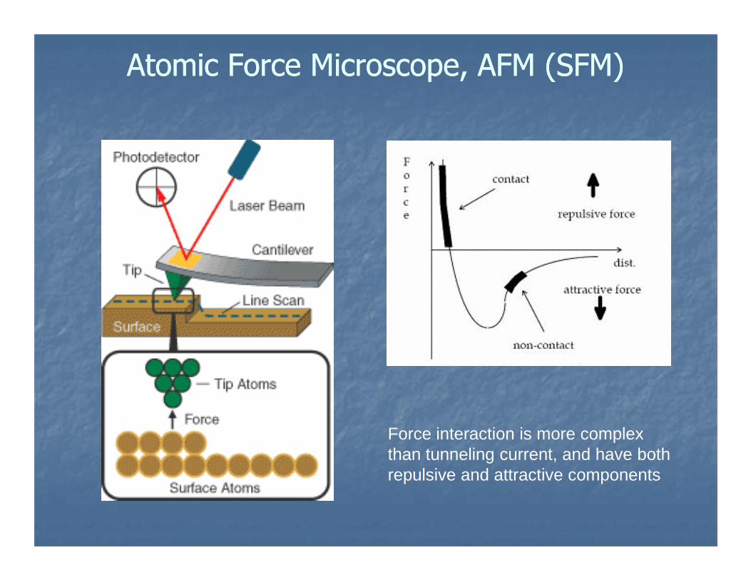
Atomic Force Microscope, AFM (SFM)Atomic Force Microscope, AFM (SFM)
Force interaction is more complex than tunneling current, and have both repulsive and attractive components
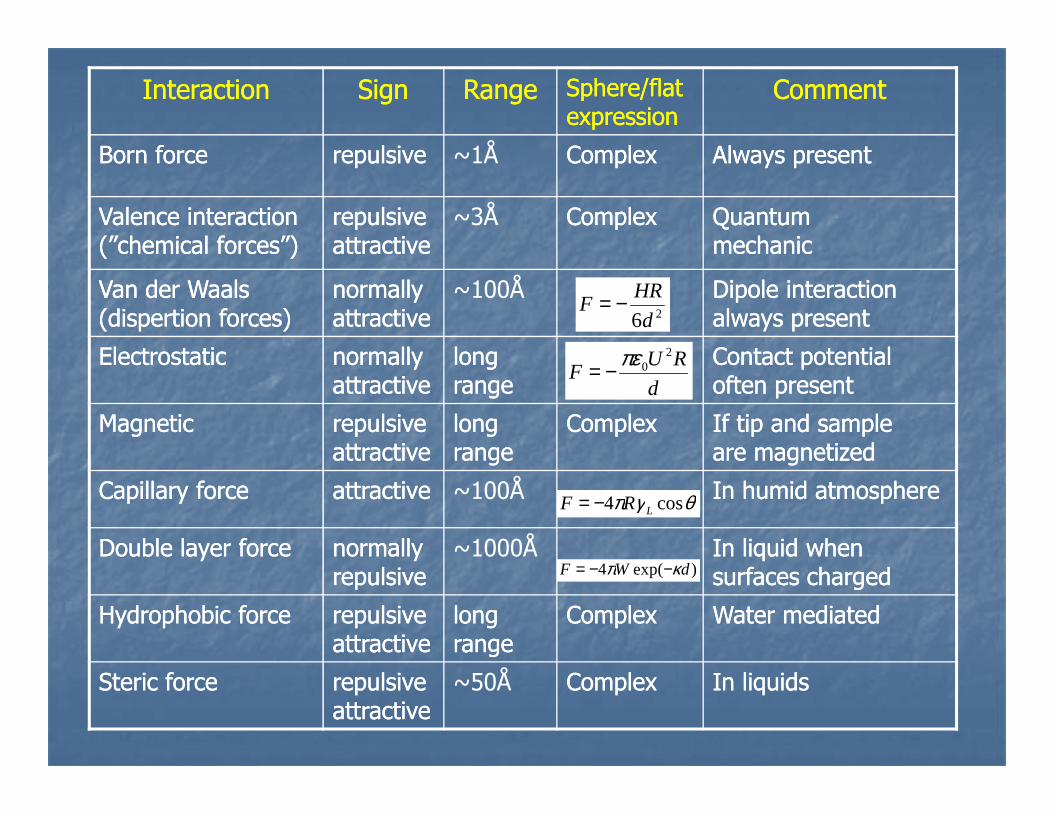
InteractionInteraction SignSign RangeRange Sphere/flatSphere/flatexpressionexpression
CommentComment
Born forceBorn force repulsiverepulsive ~1Å ComplexComplex Always presentAlways present
Valence interactionValence interaction(”chemical forces”)(”chemical forces”)
repulsiverepulsiveattractiveattractive
~3Å ComplexComplex QuantumQuantummechanicmechanic
Van der WaalsVan der Waals(dispertion forces)(dispertion forces)
normallynormallyattractiveattractive
~100Å Dipole interactionDipole interactionalways presentalways present
ElectrostaticElectrostatic normallynormallyattractiveattractive
long long rangerange
Contact potentialContact potentialoften presentoften present
26d
HRF −=
d
RUF
20πε−=
MagneticMagnetic repulsiverepulsiveattractiveattractive
long long rangerange
ComplexComplex If tip and sampleIf tip and sampleare magnetizedare magnetized
Capillary forceCapillary force attractiveattractive ~100Å In humid atmosphereIn humid atmosphere
Double layer forceDouble layer force normallynormallyrepulsiverepulsive
~1000Å In liquid when In liquid when surfaces chargedsurfaces charged
Hydrophobic forceHydrophobic force repulsiverepulsiveattractiveattractive
long long rangerange
ComplexComplex Water mediatedWater mediated
Steric forceSteric force repulsiverepulsiveattractiveattractive
~50Å ComplexComplex In liquidsIn liquids
θγπ cos4 LRF −=
)exp(4 dWF κπ −−=
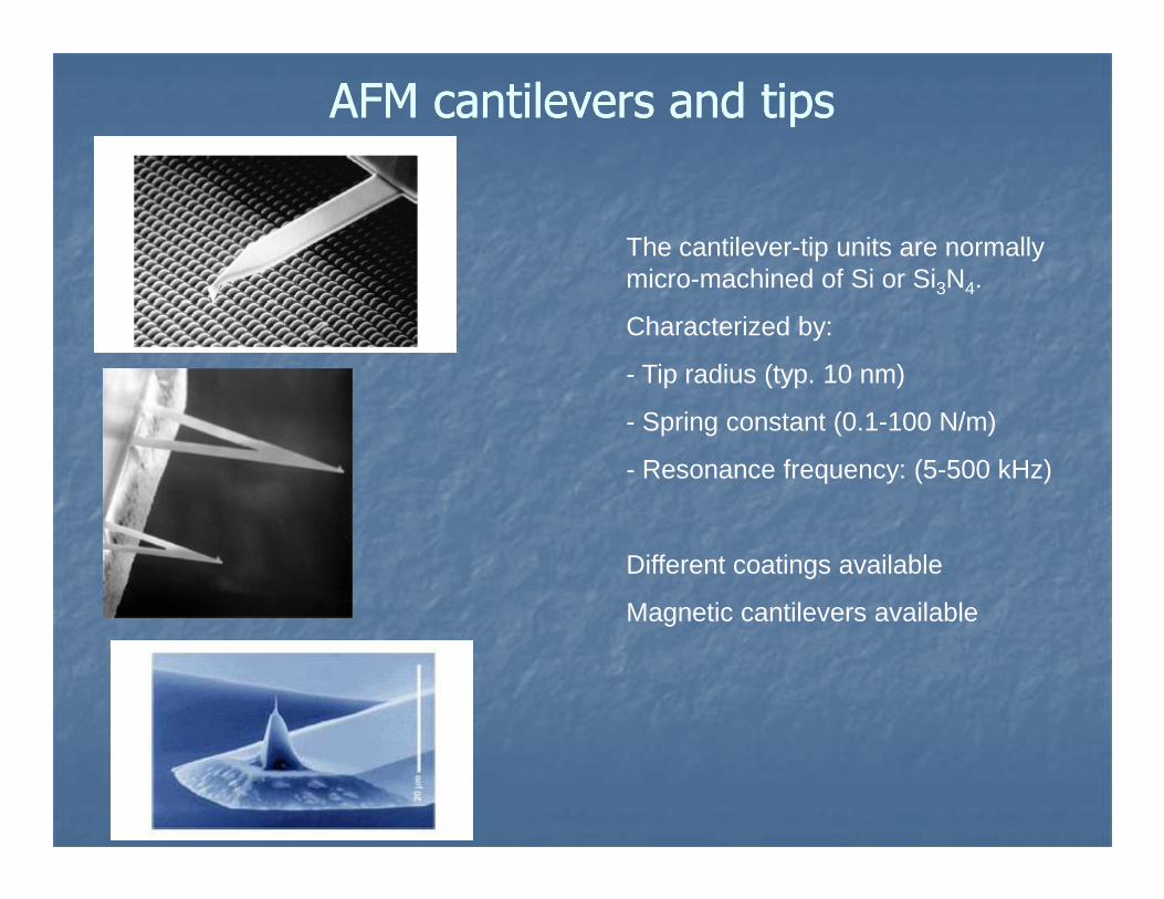
AFM cantilevers and tipsAFM cantilevers and tips
The cantilever-tip units are normally micro-machined of Si or Si3N4.
Characterized by:
- Tip radius (typ. 10 nm)
- Spring constant (0.1-100 N/m)
- Resonance frequency: (5-500 kHz)
Different coatings available
Magnetic cantilevers available
R
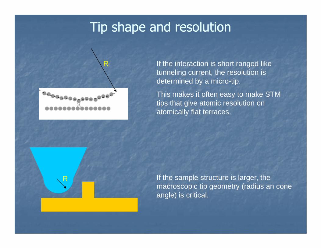
Tip shape and resolutionTip shape and resolution
If the interaction is short ranged like tunneling current, the resolution is determined by a micro-tip.
This makes it often easy to make STM tips that give atomic resolution on atomically flat terraces.
R If the sample structure is larger, the macroscopic tip geometry (radius an cone angle) is critical.
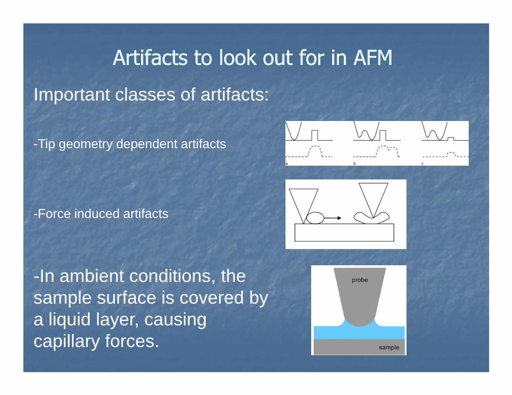
Artifacts to look out for in AFMArtifacts to look out for in AFM
Important classes of artifacts:
-Tip geometry dependent artifacts
-Force induced artifacts
-In ambient conditions, the sample surface is covered by a liquid layer, causing capillary forces.
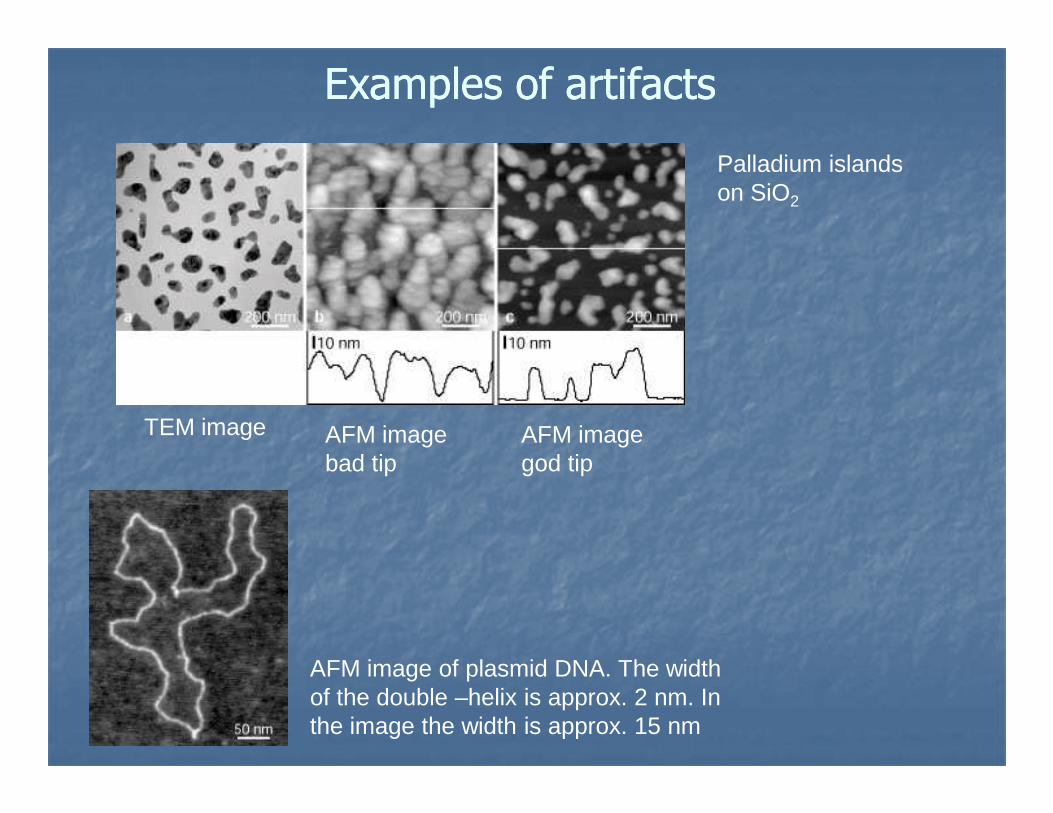
Examples of artifactsExamples of artifacts
Palladium islands on SiO2
TEM image AFM imagebad tip
AFM imagegod tip
AFM image of plasmid DNA. The width of the double –helix is approx. 2 nm. In the image the width is approx. 15 nm

Primary operation modesPrimary operation modes
Large oscillationSmall
oscillation
Contact Mode
dc operation
F=k × X, where X is lever deflectionand k spring constant.
z = f(x,y) at const. F
Non-contact Mode
ac operationsmall amplitude
z = f(x,y) at const. F’
Used for long-rangeforces like electro-static and magnetic
Intermittent-contact Mode(”Tapping Mode”)
ac operationlarge amplitude
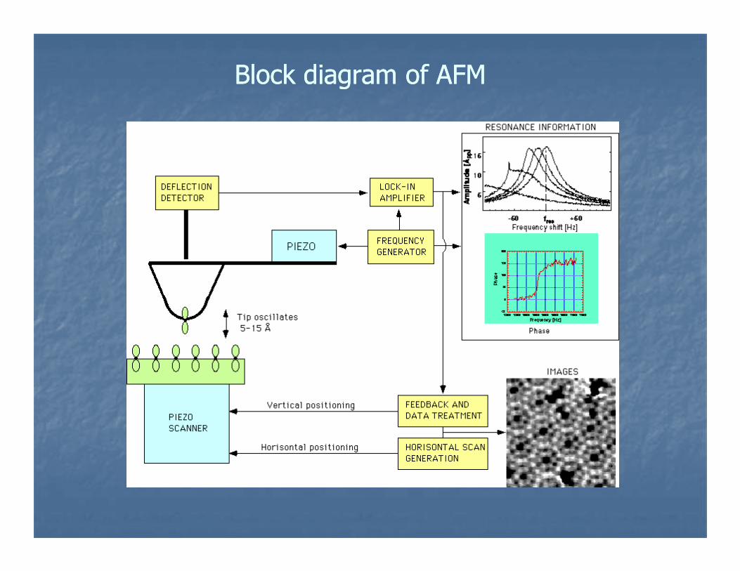
Block diagram of AFMBlock diagram of AFM

Early instruments used piezoelectric tripod scanners to move tip or sample.
Each orthogonal piezoelectric bar will extend or contract when a voltage is applied.
Modern instruments normally use compact tube scanners.
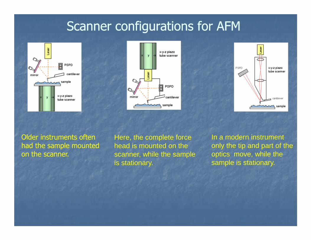
Scanner configurations for AFMScanner configurations for AFM
Older instruments often had the sample mounted on the scanner.
Here, the complete force head is mounted on the scanner, while the sample is stationary.
In a modern instrument only the tip and part of the optics move, while the sample is stationary.
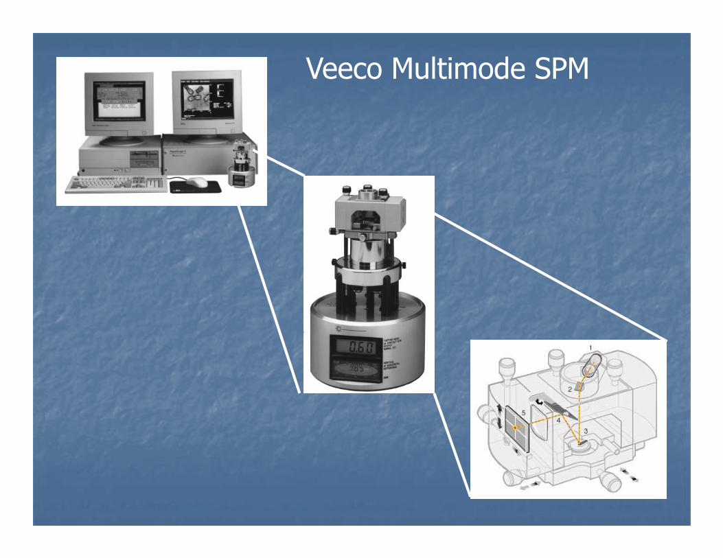
Veeco Multimode SPM
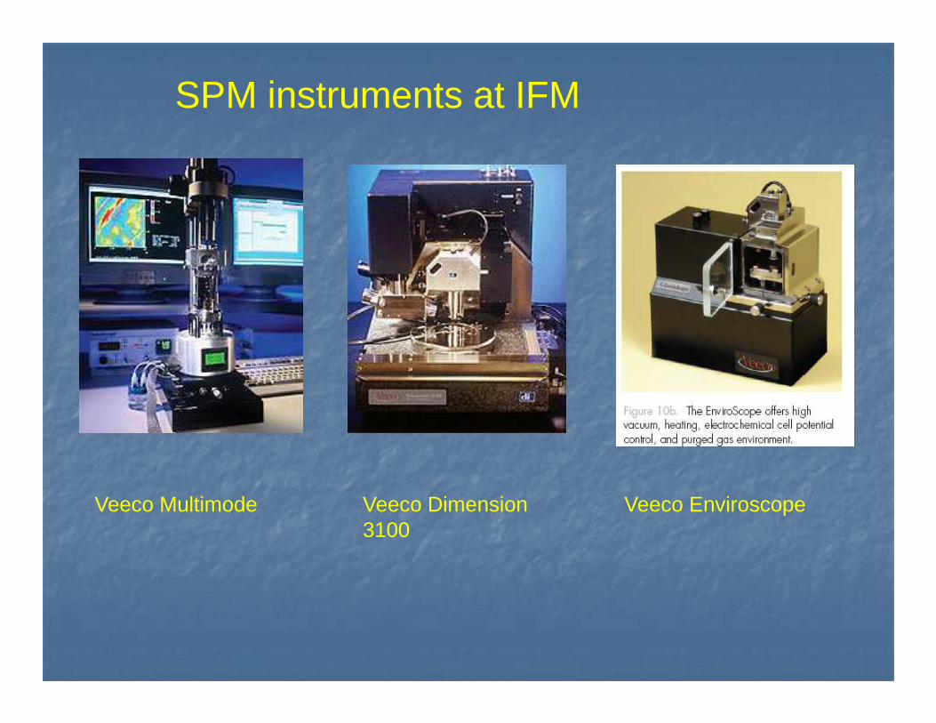
SPM instruments at IFM
Veeco Multimode Veeco Dimension 3100
Veeco Enviroscope
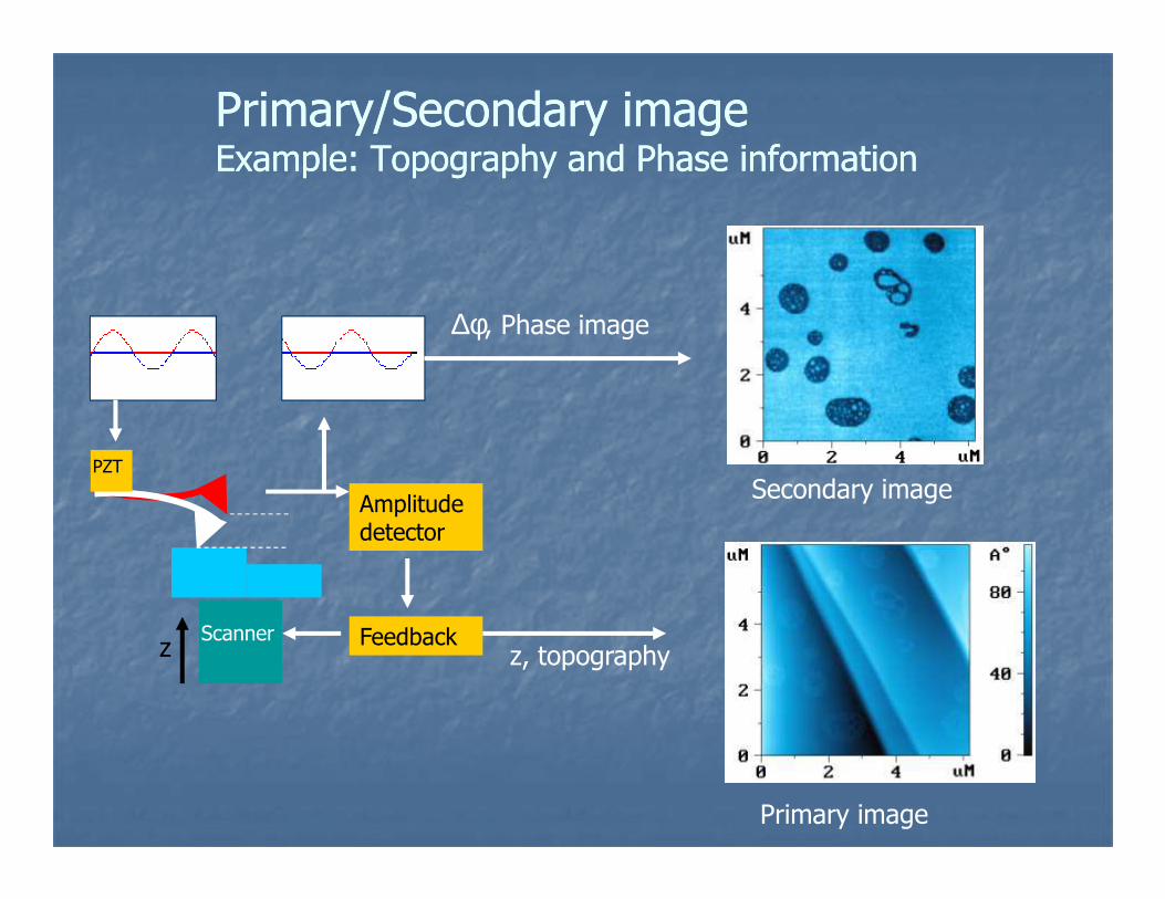
Primary/Secondary imagePrimary/Secondary imageExample: Topography and Phase informationExample: Topography and Phase information
∆φ, Phase image
Scanner
Amplitudedetector
Feedback
PZT
z z, topography
Primary image
Secondary image
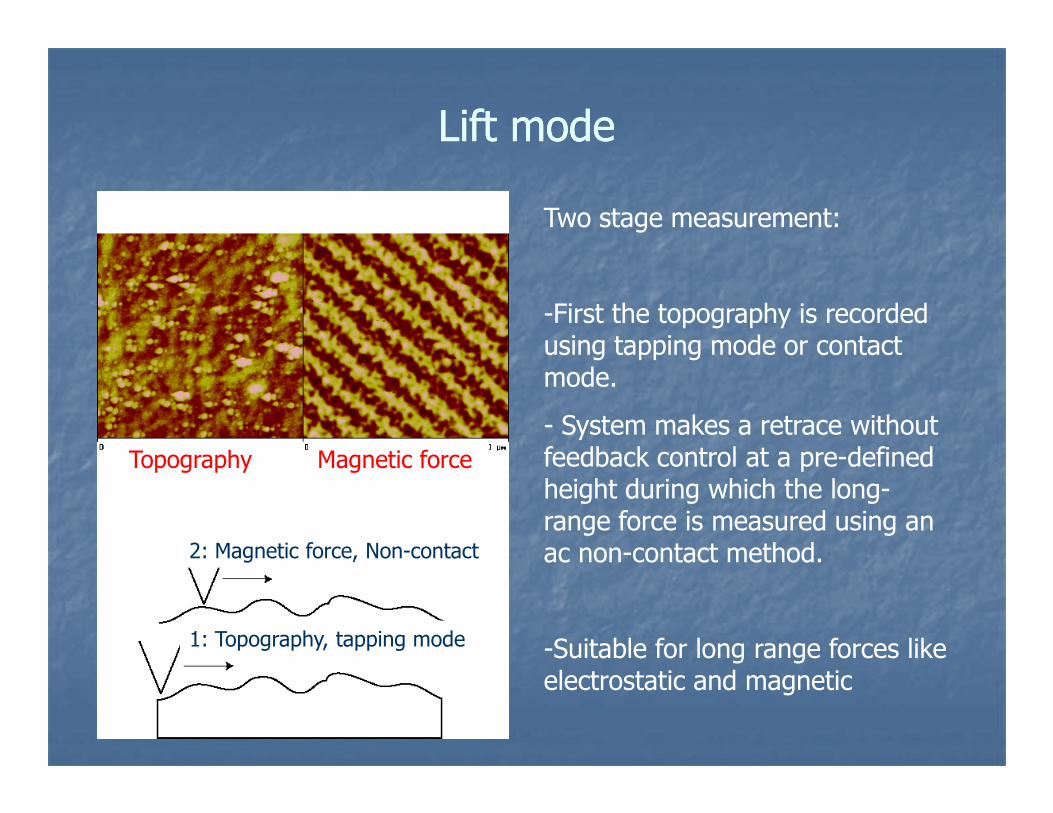
Lift modeLift mode
Two stage measurement:
-First the topography is recorded using tapping mode or contact mode.
Topography Magnetic force
1: Topography, tapping mode
2: Magnetic force, Non-contact
- System makes a retrace without feedback control at a pre-defined height during which the long-range force is measured using an ac non-contact method.
-Suitable for long range forces like electrostatic and magnetic
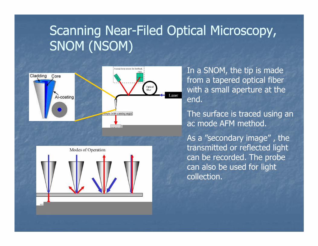
Scanning NearScanning Near--Filed Optical Microscopy, Filed Optical Microscopy, SNOM (NSOM)SNOM (NSOM)
In a SNOM, the tip is made from a tapered optical fiber with a small aperture at the end.
The surface is traced using an ac mode AFM method.ac mode AFM method.
As a ”secondary image” , the transmitted or reflected light can be recorded. The probe can also be used for light collection.
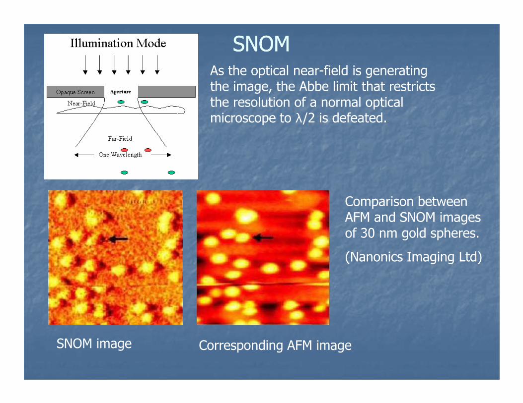
SNOMSNOMAs the optical near-field is generating the image, the Abbe limit that restricts the resolution of a normal optical microscope to λ/2 is defeated.
Comparison between
SNOM image Corresponding AFM image
Comparison between AFM and SNOM images of 30 nm gold spheres.
(Nanonics Imaging Ltd)
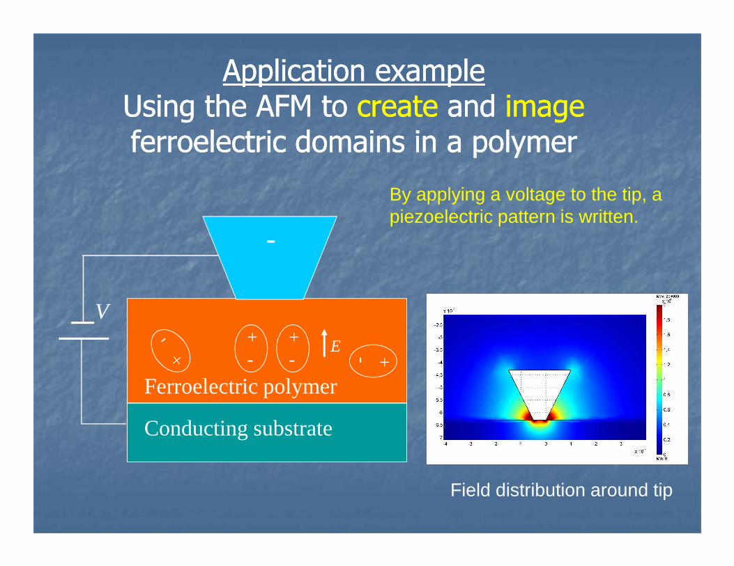
Application exampleApplication exampleUsing the AFM to Using the AFM to createcreate and and imageimageferroelectric domains in a polymerferroelectric domains in a polymer
-
By applying a voltage to the tip, a piezoelectric pattern is written.
E
Conducting substrate
V
Ferroelectric polymer
+- +-
+-
Field distribution around tip
Lock-in
5 kHz amplitude givepiezo-respons signal
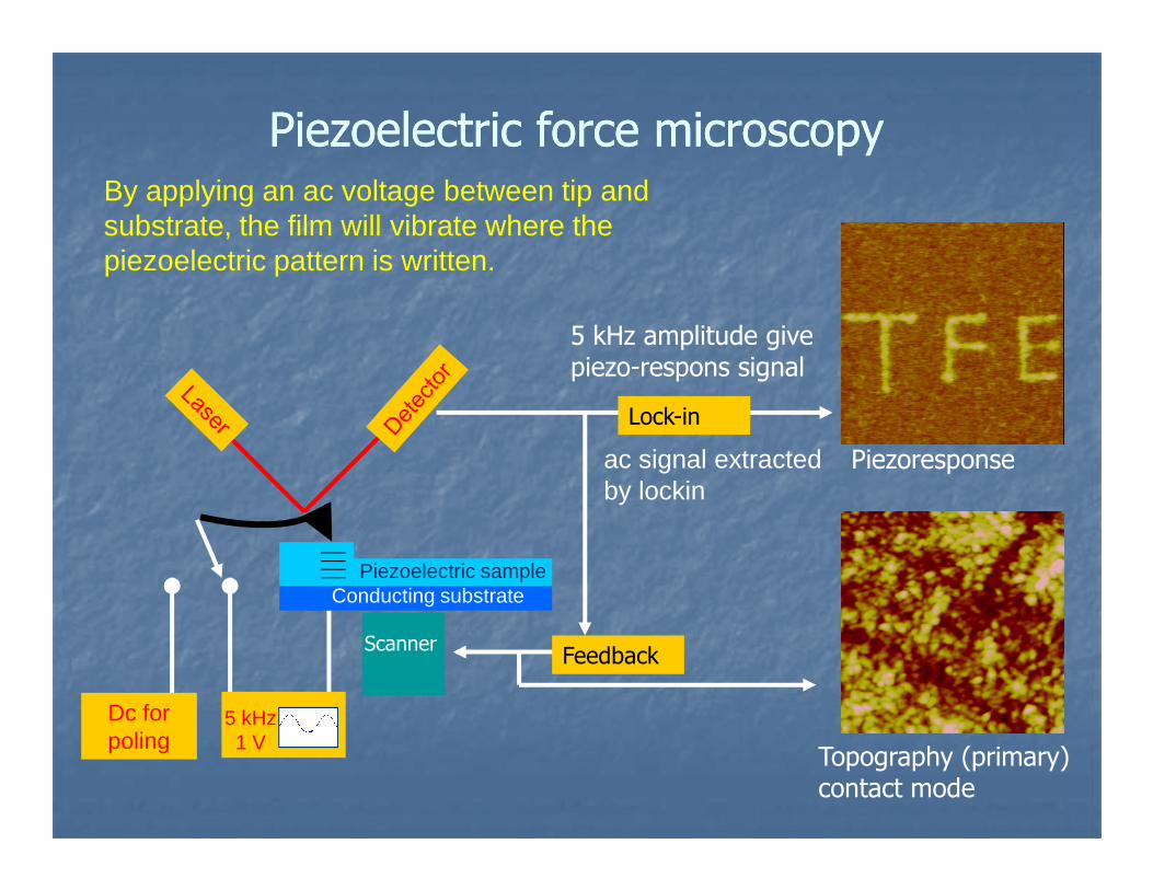
Piezoelectric force microscopyPiezoelectric force microscopy
ac signal extracted Piezoresponse
By applying an ac voltage between tip and substrate, the film will vibrate where the piezoelectric pattern is written.
Scanner Feedback
Topography (primary) contact mode
Piezoelectric sample
Dc forpoling
5 kHz1 V
Conducting substrate
ac signal extracted by lockin
Piezoresponse
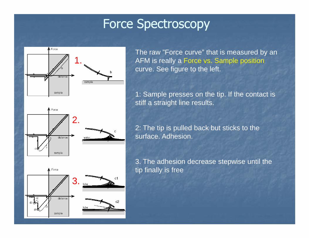
Force SpectroscopyForce Spectroscopy
The raw ”Force curve” that is measured by an AFM is really a Force vs. Sample positioncurve. See figure to the left.
1: Sample presses on the tip. If the contact is stiff a straight line results.
1.
2.2: The tip is pulled back but sticks to the surface. Adhesion.
3. The adhesion decrease stepwise until the tip finally is free
2.
3.
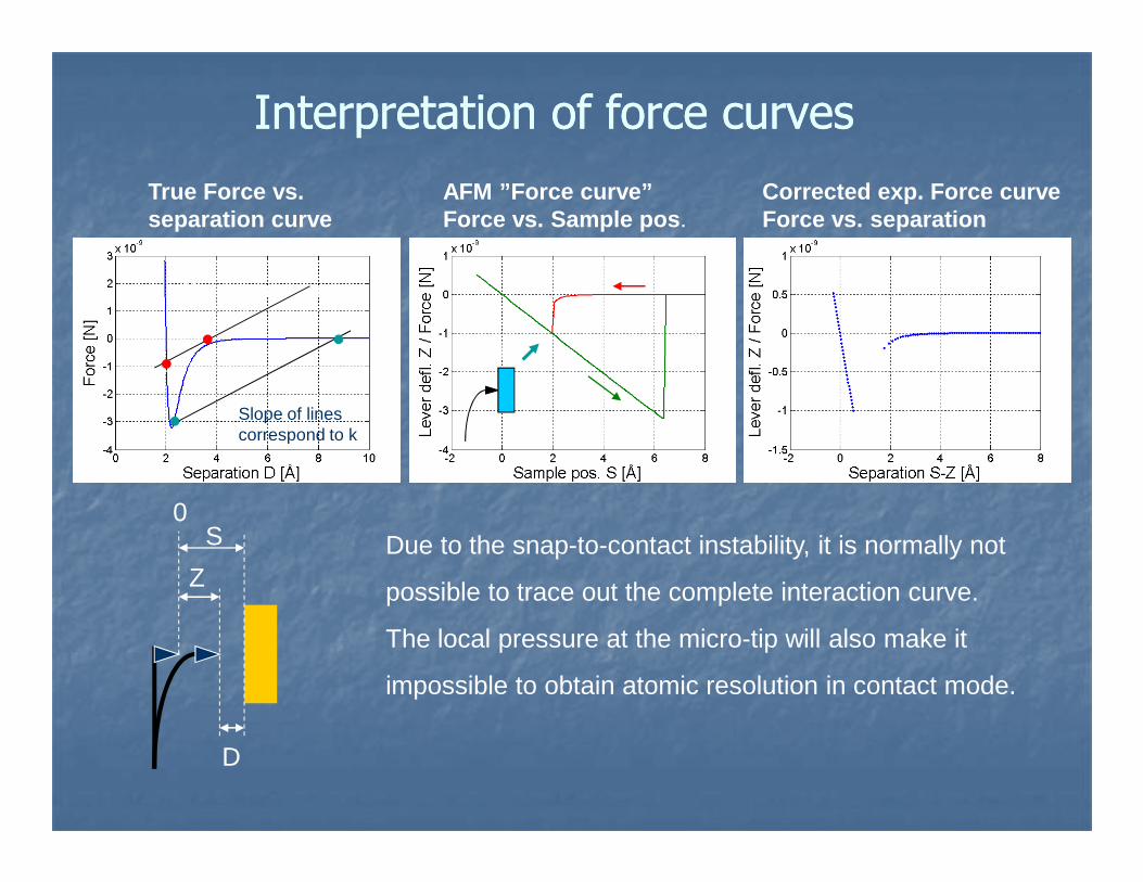
Interpretation of force curvesInterpretation of force curves
True Force vs. separation curve
AFM ”Force curve” Force vs. Sample pos .
Corrected exp. Force curve Force vs. separation
Snap-in
Cantilever spring
Slope of lines correspond to k
S
D
Z
0
correspond to k
Due to the snap-to-contact instability, it is normally not
possible to trace out the complete interaction curve.
The local pressure at the micro-tip will also make it
impossible to obtain atomic resolution in contact mode.
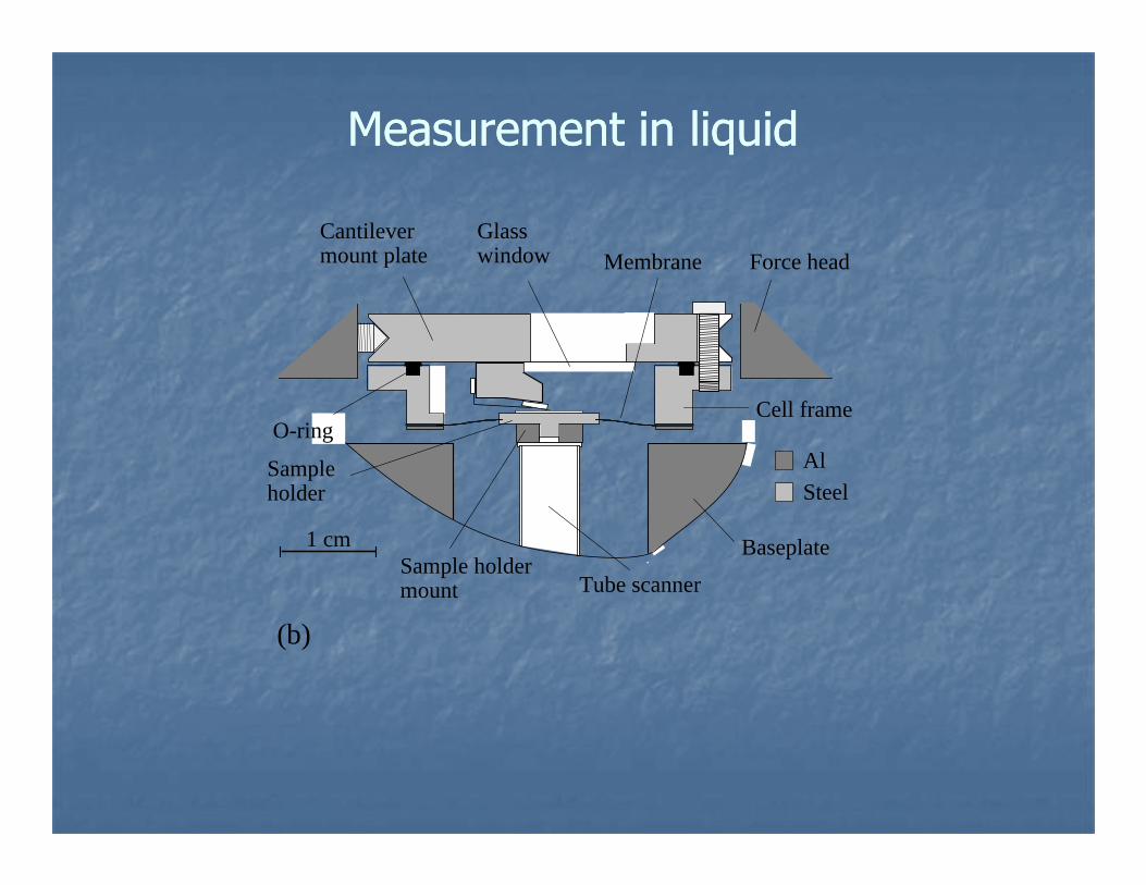
Cantilevermount plate
Glasswindow Membrane Force head
O-ringCell frame
Measurement in liquidMeasurement in liquid
1 cm
AlSteel
O-ring
Sampleholder
Tube scanner
BaseplateSample holdermount
(b)
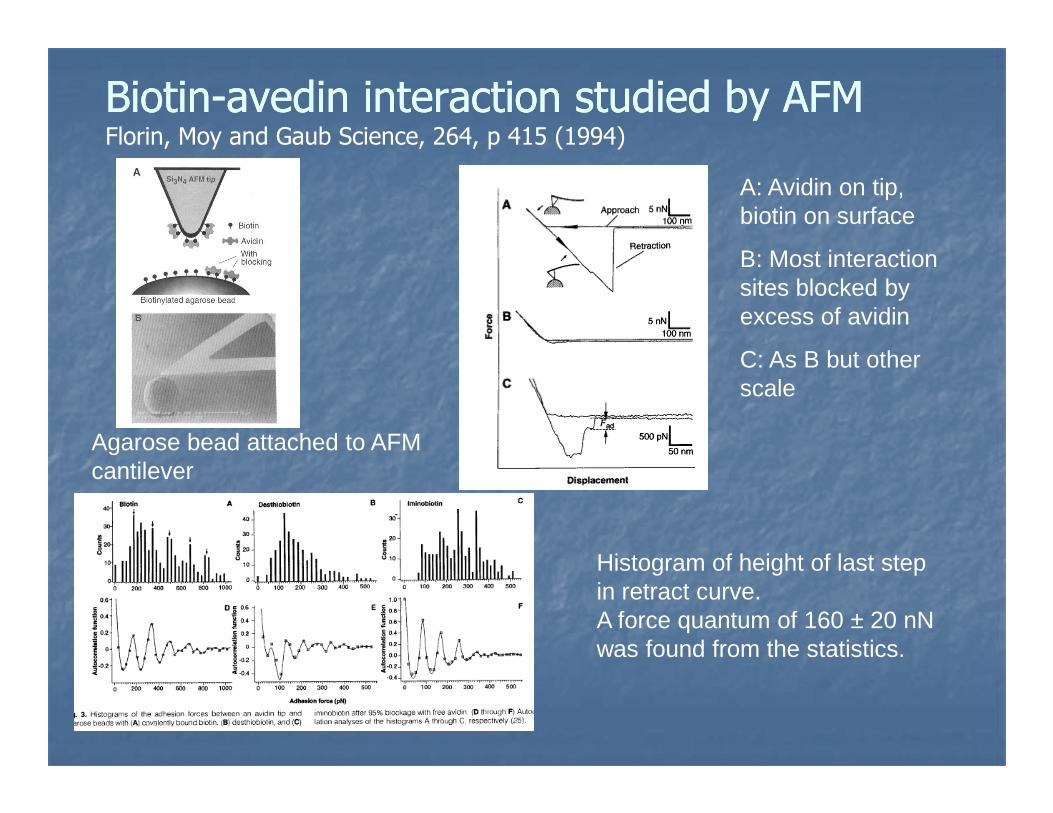
BiotinBiotin--avedin interaction studied by AFMavedin interaction studied by AFMFlorin, Moy and Gaub Science, 264, p 415 (1994)
A: Avidin on tip, biotin on surface
B: Most interaction sites blocked by excess of avidin
C: As B but other scale
Histogram of height of last step in retract curve. A force quantum of 160 ± 20 nN was found from the statistics.
Agarose bead attached to AFM cantilever
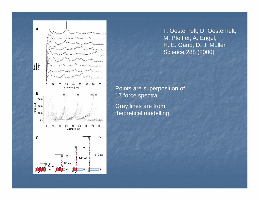
F. Oesterhelt, D. Oesterhelt, M. Pfeiffer, A. Engel, H. E. Gaub, D. J. MullerScience 288 (2000)
Points are superposition of 17 force spectra.
Grey lines are from theoretical modelling
0 5 10 15 20-5-10 25
5
10
15
0
5
-5
0
-20
20
-10
Sample position [Å]
Def
lect
ion
[Å]
Am
plitu
de [Å
pp]
For
ce [n
N]
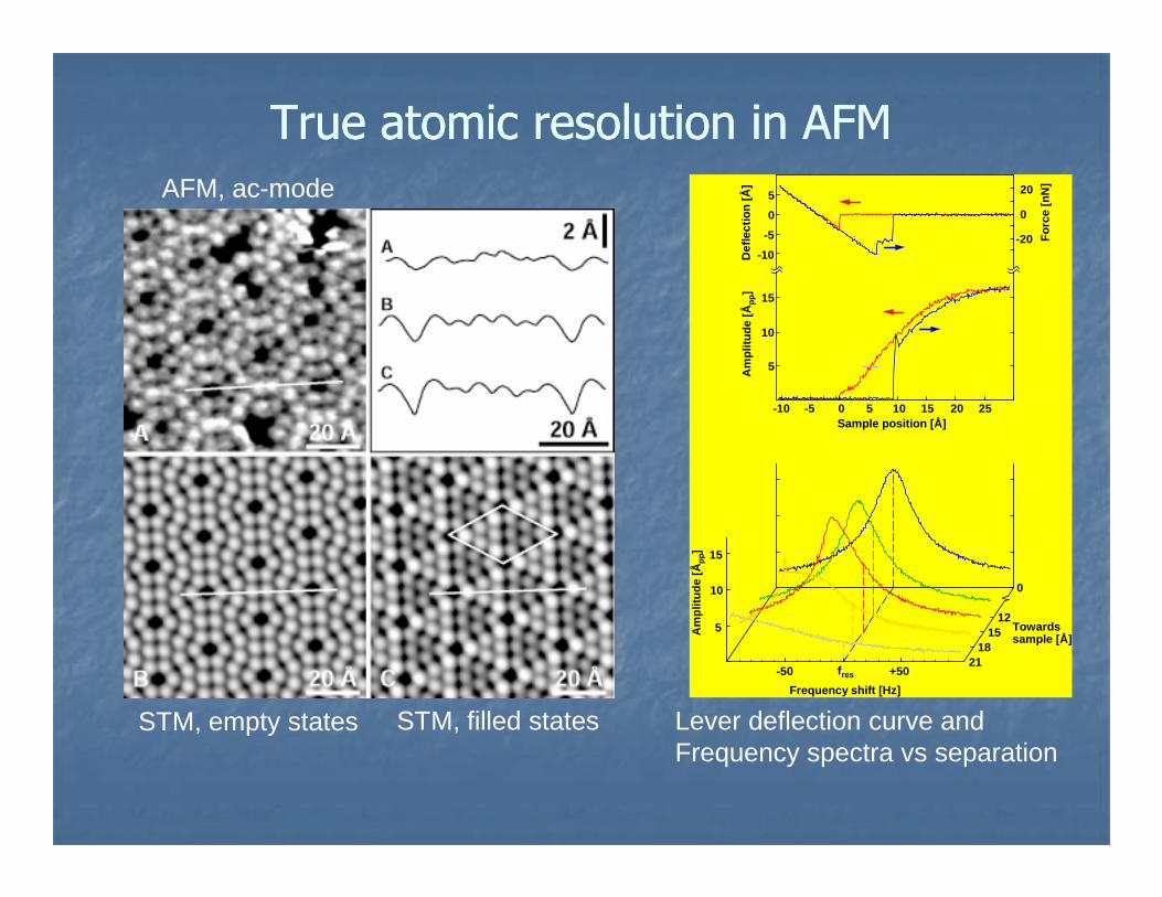
True atomic resolution in AFMTrue atomic resolution in AFMAFM, ac-mode
f res +50-50
Frequency shift [Hz]
5
10
15
2118
1512
0
Towardssample [Å]
Am
plitu
de [Å
pp]
STM, empty states STM, filled states Lever deflection curve andFrequency spectra vs separation
ConclusionsConclusions
�� Versatile techniques due to the Versatile techniques due to the multitude of multitude of interactionsinteractions that can be probedthat can be probed
�� Operates in Operates in most environmentsmost environments
�� Can Can imageimage various properties and various properties and manipulatemanipulate the the sample on the nanosample on the nano--scalescale
�� High resolution High resolution force measurementsforce measurements are important are important in many scientific fieldsin many scientific fields
Recommended