Small Tool Instruments andData Management
Digital Scale and DRO Systems
Test Equipment and Seismometers
Sensor Systems
Optical Measuring
Form Measurement
Coordinate Measuring Machines
Vision Measuring Systems
Mitutoyo Corporation20-1, Sakado 1-Chome,Takatsu-ku, Kawasaki-shi,Kanagawa 213-8533, JapanT +81 (0) 44 813-8230F +81 (0) 44 813-8231http://www.mitutoyo.co.jp
Note: All information regarding our products, and in particular the illustrations, drawings, dimensional and performance data contained in this pamphlet, as well as other technical data are to be regarded as approximate average values. We therefore reserve the right to make changes to the corresponding designs, dimensions and weights. The stated standards, similar technical regulations, descriptions and illustrations of the products were valid at the time of printing. Only quotations submitted by ourselves may be regarded as definitive.Our products are classified as regulated items under Japanese Foreign Exchange and Foreign Trade Law. Please consult us in advance if you wish to export our products to any other country. If the purchased product is exported, even though it is not a regulated item (Catch-All controls item), the customer service available for that product may be affected. If you have any questions, please consult your local Mitutoyo sales office.
Our products are classified as regulated items under Japanese Foreign Exchange and Foreign Trade Law. Please consult us in advance if you wish to export our products to any other country. If the purchased product is exported, even though it is not a regulated item (Catch-All controls item), the customer service available for that product may be affected. If you have any questions, please consult your local Mitutoyo sales office.
Catalog No. E4072-174/539
Digital Scale and DRO Systems
Linear Scales & Counters
Scale Units and Display Counters
DRO System
2
Accurate, yet Affordable, DRO System from Mitutoyo
Mitutoyo's DRO (Digital Readout) system integrates the scale units with the dedicated digital counters, to offer accurate detection and display of axial displacements of machine tools and measuring equipment. The DRO system can be configured to best meet your specific application, such as turning, milling, or grinding. Choose a suitable combination of scale unit and counter. Scale units have diverse measuring length ranges and counters feature remote zero setting, switchable resolution, and multipurpose one-touch macro keys. The DRO system has superior ease-of-use and is reliable, both of which dramatically improve machining accuracy and efficiency. Mitutoyo strongly recommends implementation of the DRO system whatever possible.
Features• Digital counter value display allows quick and correct readout
of displacement. Working efficiency thus greatly improved.• Zero-setting or presetting possible at any position. Versatile
functions eliminate calculations or complicated key operations for positioning.
• Various external output features allow output of current display values or various data to external devices such as PCs or sequencers. Easy data processing can be performed.
• Two types of display units (counters) available: high-performance type and limit signal type.
• Both linear scale and display units (counters) conform to CE marking standards. They also comply with the hazardous substances restriction in the RoHS directive (2006).
Ultra Precision Manufacture 11 Meters UndergroundMitutoyo Kiyohara Plant, which is a factory exclusively for the production of Linear Scales and other precision scales, has a complete system for producing master scales to be used in finished products, such as CMM, vision measuring system, profile projectors, and measuring microscopes. To improve the accuracy of scales and quality control technologies, the integral laboratory of Kiyohara Plant was constructed eleven meters underground. It provides an optimum environment (cleanliness factor: 100) for the ultra-precision manufacture and evaluation of scales. Its unique design and construction isolate the laboratory from external vibrations and ensure minimal variations in temperature and humidity.
Table of Contents
Scale Unit Selection Guide ............................................................ 3
AT102, Standard-size Type ............................................................ 4
AT113, Slim Type .......................................................................... 6
AT115, Slim and Economy Type .................................................... 7
AT112, Super Slim Type ................................................................ 8
AT181, Plunger Type .................................................................... 9
AT715, ABSOLUTE and High Environment Resistance Type ......... 10
Features of Scale Unit ................................................................. 11
DRO System Diagram ................................................................. 12
Display Unit Selection Guide ....................................................... 13
KA Counter ................................................................................ 14
KLD Counter .............................................................................. 15
Features of Display Unit .............................................................. 16
Connection with External Devices ............................................... 18
Caution in mounting and handling Linear Scales ........................ 22
Traceability System ..................................................................... 24
Calibration Laboratories Worldwide ........................................... 25
3
Scale Unit80
49.5
29
1.5 36
Up to 3000mm Over 3000mm
20
37.5
5095
.5
1.5 36
2332.5
151.
5 29
1.5 35
52
22
19 1.51.5±0.4
22
1.5
35
52
191.5±0.2
15.4
15.2
0.2±0.3
44.5 30
1±0.
3
42
2011
7 28
70282135
21
22
(1.5)191.5±0.2
(54)36
.516
1.5
AT102Standard-size Type
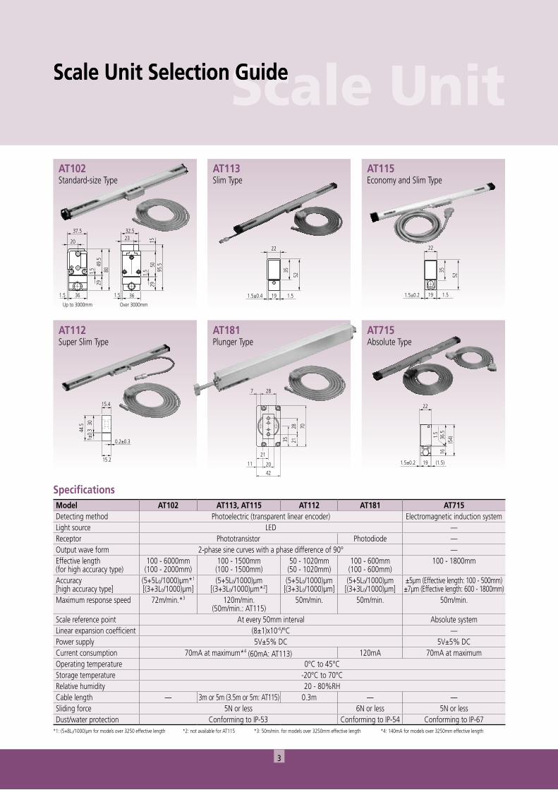
Scale Unit Selection Guide
SpecificationsModel AT102 AT113, AT115 AT112 AT181 AT715Detecting method Photoelectric (transparent linear encoder) Electromagnetic induction systemLight source LED —Receptor Phototransistor Photodiode —Output wave form 2-phase sine curves with a phase difference of 90° —Effective length(for high accuracy type)
100 - 6000mm(100 - 2000mm)
100 - 1500mm(100 - 1500mm)
50 - 1020mm(50 - 1020mm)
100 - 600mm(100 - 600mm)
100 - 1800mm
Accuracy[high accuracy type]
(5+5L0/1000)µm*1
[(3+3L0/1000)µm](5+5L0/1000)µm
[(3+3L0/1000)µm*2](5+5L0/1000)µm[(3+3L0/1000)µm]
(5+5L0/1000)µm[(3+3L0/1000)µm]
±5µm (Effective length: 100 - 500mm)±7µm (Effective length: 600 - 1800mm)
Maximum response speed 72m/min.*3 120m/min.(50m/min.: AT115)
50m/min. 50m/min. 50m/min.
Scale reference point At every 50mm interval Absolute systemLinear expansion coefficient (8±1)x10-6/°C —Power supply 5V±5% DC 5V±5% DCCurrent consumption 70mA at maximum*4 (60mA: AT113) 120mA 70mA at maximumOperating temperature 0°C to 45°CStorage temperature -20°C to 70°CRelative humidity 20 - 80%RHCable length — 3m or 5m (3.5m or 5m: AT115) 0.3m — —Sliding force 5N or less 6N or less 5N or lessDust/water protection Conforming to IP-53 Conforming to IP-54 Conforming to IP-67
*1: (5+8L0/1000)µm for models over 3250 effective length *2: not available for AT115 *3: 50m/min. for models over 3250mm effective length *4: 140mA for models over 3250mm effective length
AT113Slim Type
AT112Super Slim Type
AT181Plunger Type
AT715Absolute Type
AT115Economy and Slim Type
Scale Unit Selection Guide
4
20 (.79"
)
10 (.
39")7(.28")10 (.39)
7 (.2
8)
20 (.
79)
Spar mounting surface
31±0
.3(1.2
2"±.12
")
10 (.39")
L3
27(1
.06"
)
10
(.39"
)
7 (.28")
12.6
(.496
")
8 (.3
1")
7 (.28")
11.6 (.457")
60 (2.36")
90 (3.54")
7(.2
8")
27(1.
06")
Signal cableØ7mm through hole (x 2pcs.), Ø11mm hole on bothsides (6.5mm deep)
80(3
.15"
)
1.5 ±0
.2(.0
59"±
.008"
)
49.5
(1.9
49")
29(1.
14")
Air supplymouth (M5)
36(1.42")
20 (.79")
37.5 (1.476")
Hex-n
ut (ø
11m
m)
Hole
5mm
dee
p
Viewed from X
28.5
(1.1
22")
6 (.24")6 (.2
4")
20 (.79")L6
L5
L6
L410 (.39")
B CABracket Adjustable
L2
L1
L0
Detecting head mounting plane
Spar mounting surface
L6
L5
L6
23.5
(.92
5")
L4
B CA2.1 (.083") Adjustable
Bracket
Mounting method 2
6 (.2
4") 20 (.79")
6 (.24")
10 (.39")Mounting method 1
X
1.5 ±0.2(.059"±.008")
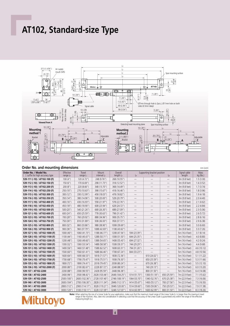
AT102, Standard-size Type
Order No. and mounting dimensions mm (inch)
Order No. / Model No.( ): suffix for high accuracy type
Effectiverange L0
Travelrange L1
Mountinterval L2
Overalllength L3
Supporting bracket position L4 L5 L6
Signal cablelength
Mass kg (lbs.)
539-111 (-10) / AT102-100 (F) 100 (4”) 120 (4.72”) 248 (9.76”) 268 (10.55”) — — — 3m (9.8 feet) 1.5 (3.30)539-112 (-10) / AT102-150 (F) 150 (6”) 170 (6.69”) 298 (11.73”) 318 (12.52”) — — — 3m (9.8 feet) 1.6 (3.52)539-113 (-10) / AT102-200 (F) 200 (8”) 220 (8.66”) 348 (13.70”) 368 (14.49”) — — — 3m (9.8 feet) 1.7 (3.74)539-114 (-10) / AT102-250 (F) 250 (10”) 270 (10.63”) 398 (15.67”) 418 (16.46”) — — — 3m (9.8 feet) 1.8 (3.96)539-115 (-10) / AT102-300 (F) 300 (12”) 330 (12.99”) 458 (18.03”) 478 (18.82”) — — — 3m (9.8 feet) 1.9 (4.18)539-116 (-10) / AT102-350 (F) 350 (14”) 380 (14.96”) 508 (20.00”) 528 (20.79”) — — — 3m (9.8 feet) 2.0 (4.40)539-117 (-10) / AT102-400 (F) 400 (16”) 430 (16.93”) 558 (21.97”) 578 (22.76”) — — — 3m (9.8 feet) 2.1 (4.62)539-118 (-10) / AT102-450 (F) 450 (18”) 480 (18.90”) 608 (23.94”) 628 (24.72”) — — — 3m (9.8 feet) 2.2 (4.84)539-119 (-10) / AT102-500 (F) 500 (20”) 540 (21.26”) 668 (26.30”) 688 (27.09”) — — — 3m (9.8 feet) 2.3 (5.06)539-121 (-10) / AT102-600 (F) 600 (24”) 650 (25.59”) 778 (30.63”) 798 (31.42”) — — — 3m (9.8 feet) 2.6 (5.72)539-123 (-10) / AT102-700 (F) 700 (28”) 760 (29.92”) 888 (34.96”) 908 (35.75”) — — — 3m (9.8 feet) 2.8 (6.16)539-124 (-10) / AT102-750 (F) 750 (30”) 810 (31.89”) 938 (36.93”) 958 (37.72”) — — — 3m (9.8 feet) 2.9 (6.38)
539-125 (-10) / AT102-800 (F) 800 (32”) 860 (33.86”) 988 (38.90”) 1008 (39.69”) — — — 3m (9.8 feet) 3.0 (6.60)539-126 (-10) / AT102-900 (F) 900 (36”) 960 (37.79”) 1088 (42.83”) 1108 (43.62”) — — — 3m (9.8 feet) 3.3 (7.26)539-127 (-10) / AT102-1000 (F) 1000 (40”) 1060 (41.73”) 1188 (46.77”) 1208 (47.56”) 594 (23.39”) — — 5m (16.4 feet) 3.7 (8.14)539-128 (-10) / AT102-1100 (F) 1100 (44”) 1160 (45.67”) 1288 (50.71”) 1308 (51.50”) 644 (25.35”) — — 5m (16.4 feet) 4.0 (8.80)539-129 (-10) / AT102-1200 (F) 1200 (48”) 1260 (49.60”) 1388 (54.65”) 1408 (55.43”) 694 (27.32”) — — 5m (16.4 feet) 4.2 (9.24)539-130 (-10) / AT102-1300 (F) 1300 (52”) 1360 (53.54”) 1488 (58.58”) 1508 (59.37”) 744 (29.29”) — — 5m (16.4 feet) 4.4 (9.68)539-131 (-10) / AT102-1400 (F) 1400 (56”) 1460 (57.48”) 1588 (62.52”) 1608 (63.31”) 794 (31.26”) — — 5m (16.4 feet) 4.6 (10.12)539-132 (-10) / AT102-1500 (F) 1500 (60”) 1560 (61.41”) 1688 (66.46”) 1708 (67.24”) 844 (33.23”) — — 5m (16.4 feet) 4.8 (10.56)539-133 (-10) / AT102-1600 (F) 1600 (64”) 1690 (66.53”) 1818 (71.57”) 1838 (72.36”) — 610 (24.02”) — 5m (16.4 feet) 5.1 (11.22)539-134 (-10) / AT102-1700 (F) 1700 (68”) 1790 (70.47”) 1918 (75.51”) 1938 (76.30”) — 650 (25.59”) — 5m (16.4 feet) 5.3 (11.66)539-135 (-10) / AT102-1800 (F) 1800 (72”) 1890 (74.41”) 2018 (79.45”) 2038 (80.24”) — 670 (26.38”) — 5m (16.4 feet) 5.5 (12.10)539-136 (-10) / AT102-2000 (F) 2000 (80”) 2100 (82.67”) 2228 (87.72”) 2248 (88.50”) — 740 (29.13”) — 5m (16.4 feet) 6.0 (13.20)539-137 / AT102-2200 2200 (88”) 2300 (90.55”) 2428 (95.59”) 2448 (96.38”) — 800 (31.50”) — 5m (16.4 feet) 6.4 (14.08)539-138 / AT102-2400 2400 (96”) 2500 (98.42”) 2628 (103.46”) 2648 (104.25”) 1314 (51.73”) 1300 (51.18”) 650 (25.59”) 7m (22.9 feet) 7.1 (15.62)539-139 / AT102-2500 2500 (100”) 2600 (102.36”) 2728 (107.40”) 2748 (108.19”) 1364 (53.70”) 1340 (52.76”) 670 (25.38”) 7m (22.9 feet) 7.3 (16.06)539-140 / AT102-2600 2600 (104”) 2700 (106.30”) 2828 (111.34”) 2848 (112.13”) 1414 (55.67”) 1400 (55.12”) 700 (27.56”) 7m (22.9 feet) 7.5 (16.50)539-141 / AT102-2800 2800 (112”) 2900 (114.17”) 3028 (119.21”) 3048 (120.00”) 1514 (59.60”) 1500 (59.06”) 750 (29.53”) 7m (22.9 feet) 7.9 (17.38)539-142 / AT102-3000 3000 (120”) 3100 (118.11”) 3228 (127.09”) 3248 (127.87”) 1614 (63.99”) 1600 (62.99”) 800 (31.50”) 7m (22.9 feet) 8.3 (18.26)
Note) When selecting the size of a Linear Scale for your application, make sure that the maximum travel range of the Linear Scale (L1) is larger than the maximum travel range of the machine. Also, take into consideration in selecting a size that the accuracy of the Linear Scale is guaranteed only within the range of the effective measuring length (L0).
5
Scale UnitL3L4L3
L5L5L5L5
60 (2.36") 80 (3.15")
40 (1.57")
60 (2.36")
90 (3.54")
35 (1
.38"
)2.
5 (.1
0")
L0
L1
L2
50 (1
.97"
)
95.5
(3.7
6")
1.5±0.2(.059"±.008")
1.5±
0.2
(.059
"±.00
8")
36(1.42")
23 (.91")
32.5(1.28")
7.5
(.30"
)
X
15 (.
59")
Detecting head mounting surfaceSpar mounting surface
29 (1
.14"
)
(Adjustable) (Adjustable) (Adjustable)(Adjustable)(Fixed)
Ø7mm through hole (x 2pcs.),Ø11mm hole on bothsides (6.5mm deep)
Ø8mm throughhole (x 2pcs.)
Spar mountingblock
Hex-n
ut h
ole,
Ø11m
m (5
mm
dee
p)
Viewed from X
66±0
.3(2
.60"
±.01
2")
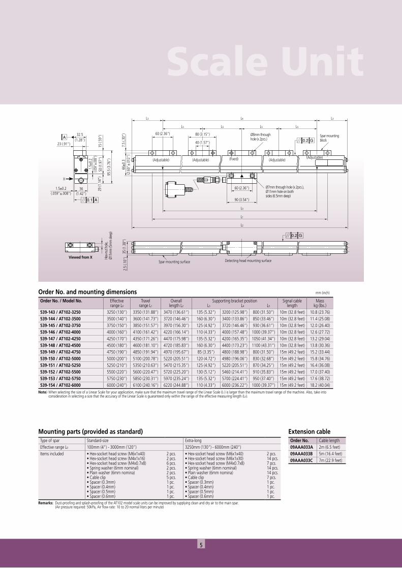
Order No. and mounting dimensions mm (inch)
Order No. / Model No. Effectiverange L0
Travelrange L1
Overalllength L2
Supporting bracket position L3 L4 L5
Signal cablelength
Masskg (lbs.)
539-143 / AT102-3250 3250 (130”) 3350 (131.88”) 3470 (136.61”) 135 (5.32”) 3200 (125.98”) 800 (31.50”) 10m (32.8 feet) 10.8 (23.76)539-144 / AT102-3500 3500 (140”) 3600 (141.73”) 3720 (146.46”) 160 (6.30”) 3400 (133.86”) 850 (33.46”) 10m (32.8 feet) 11.4 (25.08)539-145 / AT102-3750 3750 (150”) 3850 (151.57”) 3970 (156.30”) 125 (4.92”) 3720 (146.46”) 930 (36.61”) 10m (32.8 feet) 12.0 (26.40)539-146 / AT102-4000 4000 (160”) 4100 (161.42”) 4220 (166.14”) 110 (4.33”) 4000 (157.48”) 1000 (39.37”) 10m (32.8 feet) 12.6 (27.72)539-147 / AT102-4250 4250 (170”) 4350 (171.26”) 4470 (175.98”) 135 (5.32”) 4200 (165.35”) 1050 (41.34”) 10m (32.8 feet) 13.2 (29.04)539-148 / AT102-4500 4500 (180”) 4600 (181.10”) 4720 (185.83”) 160 (6.30”) 4400 (173.23”) 1100 (43.31”) 10m (32.8 feet) 13.8 (30.36)539-149 / AT102-4750 4750 (190”) 4850 (191.94”) 4970 (195.67”) 85 (3.35”) 4800 (188.98”) 800 (31.50”) 15m (49.2 feet) 15.2 (33.44)539-150 / AT102-5000 5000 (200”) 5100 (200.78”) 5220 (205.51”) 120 (4.72”) 4980 (196.06”) 830 (32.68”) 15m (49.2 feet) 15.8 (34.76)539-151 / AT102-5250 5250 (210”) 5350 (210.63”) 5470 (215.35”) 125 (4.92”) 5220 (205.51”) 870 (34.25”) 15m (49.2 feet) 16.4 (36.08)539-152 / AT102-5500 5500 (220”) 5600 (220.47”) 5720 (225.20”) 130 (5.12”) 5460 (214.41”) 910 (35.83”) 15m (49.2 feet) 17.0 (37.40)539-153 / AT102-5750 5750 (230”) 5850 (230.31”) 5970 (235.24”) 135 (5.32”) 5700 (224.41”) 950 (37.40”) 15m (49.2 feet) 17.6 (38.72)539-154 / AT102-6000 6000 (240”) 6100 (240.16”) 6220 (244.88”) 110 (4.33”) 6000 (236.22”) 1000 (39.37”) 15m (49.2 feet) 18.2 (40.04)
Mounting parts (provided as standard)Type of spar Standard-size Extra-longEffective range L0 100mm (4”) - 3000mm (120”) 3250mm (130”) - 6000mm (240”)Items included • Hex-socket head screw (M6x1x40)
• Hex-socket head screw (M4x1x16)• Hex-socket head screw (M4x0.7x8)• Spring washer (6mm nominal)• Plain washer (6mm nomina)• Cable clip• Spacer (0.3mm)• Spacer (0.4mm)• Spacer (0.5mm)• Spacer (0.6mm)
2 pcs.2 pcs.6 pcs.2 pcs.2 pcs.5 pcs.1 pc.1 pc.1 pc.1 pc.
• Hex-socket head screw (M6x1x40)• Hex-socket head screw (M6x1x30)• Hex-socket head screw (M4x0.7x8)• Spring washer (6mm nominal)• Plain washer (6mm nomina)• Cable clip• Spacer (0.3mm)• Spacer (0.4mm)• Spacer (0.5mm)• Spacer (0.6mm)
2 pcs.14 pcs.7 pcs.14 pcs.14 pcs.7 pcs.1 pc.1 pc.1 pc.1 pc.
Remarks: Dust-proofing and splash-proofing of the AT102 model scale units can be improved by supplying clean and dry air to the main spar. (Air pressure required: 50kPa, Air flow rate: 10 to 20 normal liters per minute)
Extension cableOrder No. Cable length09AAA033A 2m (6.5 feet)09AAA033B 5m (16.4 feet)09AAA033C 7m (22.9 feet)
Note) When selecting the size of a Linear Scale for your application, make sure that the maximum travel range of the Linear Scale (L1) is larger than the maximum travel range of the machine. Also, take into consideration in selecting a size that the accuracy of the Linear Scale is guaranteed only within the range of the effective measuring length (L0).
6
80±0.2(3.15"±.008")
Spar mounting surface
35 (1
.38"
)
52 (2
.05"
)
22 (.87")
19(.75")
1.5 (.059")1.5±0.4(.059"±.016")
10 (.
394"
)
17 (.
67")
7 (.28")
14 (.55")
Hole on bothsides (6.5mmdeep)
Head cable Length: 0.3m (12")
94 (3.70")
1 (.3
9")
33 (1
.30"
)
L0
L1
L2
L4
28 (1.10")
9 (.354") 9 (.354")
17.5
(.689
")28
±0.4
(1.1
0"±.
016"
)
Signal cable
M6 through hole (x 2pcs.),Ø9mm hole on bothsides (4.5mm deep)
B CA
L5
5 (.2
0")
21.5
(.84
6")
12 (.47") L7
9 (.35")
Ø5 (.20")
(Fixed)
15 (.
59")
5 (.2
0")
B CA12 (.47") Ø5 (.20")
L7
17 (.67")L61 (.04")
80±0.2(3.15"±.008")
Ø7mm through hole (x 2pcs.),Ø14mm hole on bothsides (6.5mm deep)
L3
M4x0.7 (x 2pcs.),5mm deep18 (.71")
11 (.
43")
1(.0
4")
G: machine guide
Spar mounting surface
Bracket
Mounting method 1
Bracket
(Fixed)
(Fixed) (Fixed) (Fixed)
(Fixed)
1 (.04")
1(.0
4")
Mounting method 2
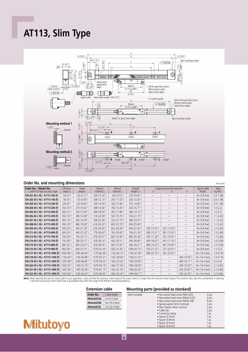
AT113, Slim Type
Order No. and mounting dimensions mm (inch)
Order No. / Model No.( ): suffix for high accuracy type
Effectiverange L0
Travelrange L1
Mountinterval L2
Mountinterval L3
Overalllength L4
Supporting bracket position L5 L6 L7
Signal cablelength
Mass kg (lbs.)
539-201-30 (-10) / AT113-100 (F) 100 (4”) 120 (4.72”) 258 (10.16”) 242 (9.53”) 276 (10.87”) — — — 3m (9.8 feet) 0.9 (1.98)539-202-30 (-10) / AT113-150 (F) 150 (6”) 170 (6.69”) 308 (12.13”) 292 (11.50”) 326 (12.83”) — — — 3m (9.8 feet) 0.9 (1.98)539-203-30 (-10) / AT113-200 (F) 200 (8”) 220 (8.66”) 358 (14.09”) 342 (13.46”) 376 (14.80”) — — — 3m (9.8 feet) 0.9 (1.98)539-204-30 (-10) / AT113-250 (F) 250 (10”) 270 (10.63”) 408 (16.06”) 392 (15.43”) 426 (16.77”) — — — 3m (9.8 feet) 1.0 (2.2)539-205-30 (-10) / AT113-300 (F) 300 (12”) 330 (12.99”) 468 (18.43”) 452 (17.80”) 486 (19.13”) — — — 3m (9.8 feet) 1.0 (2.2)539-206-30 (-10) / AT113-350 (F) 350 (14”) 380 (14.96”) 518 (20.39”) 502 (19.76”) 536 (21.10”) — — — 3m (9.8 feet) 1.1 (2.42)539-207-30 (-10) / AT113-400 (F) 400 (16”) 430 (16.93”) 568 (22.36”) 552 (21.73”) 586 (23.07”) — — — 3m (9.8 feet) 1.1 (2.42)539-208-30 (-10) / AT113-450 (F) 450 (18”) 480 (18.90”) 618 (24.33”) 602 (23.70”) 636 (25.04”) — — — 3m (9.8 feet) 1.1 (2.42)539-209-30 (-10) / AT113-500 (F) 500 (20”) 540 (21.26”) 678 (26.69”) 662 (26.06”) 696 (27.40”) 339 (13.35”) 331 (13.03”) — 3m (9.8 feet) 1.2 (2.64)539-211-30 (-10) / AT113-600 (F) 600 (24”) 640 (25.20”) 778 (30.63”) 762 (30.00”) 796 (31.34”) 389 (15.31”) 381 (15.00”) — 3m (9.8 feet) 1.3 (2.86)539-213-30 (-10) / AT113-700 (F) 700 (28”) 740 (29.13”) 878 (34.57”) 862 (33.94”) 896 (35.28”) 439 (17.28”) 431 (16.97”) — 3m (9.8 feet) 1.3 (2.86)539-214-30 (-10) / AT113-750 (F) 750 (30”) 780 (30.71”) 918 (36.14”) 902 (35.51”) 936 (36.85”) 459 (18.07”) 451 (17.76”) — 3m (9.8 feet) 1.4 (3.08)539-215-30 (-10) / AT113-800 (F) 800 (32”) 840 (33.07”) 978 (38.50”) 962 (37.87”) 996 (39.21”) 489 (19.25”) 481 (18.94”) — 3m (9.8 feet) 1.4 (3.08)539-216-30 (-10) / AT113-900 (F) 900 (36”) 940 (37.01”) 1078 (42.44”) 1062 (41.81”) 1096 (43.15”) 539 (21.22”) 531 (20.91”) — 3m (9.8 feet) 1.5 (3.3)539-217-30 (-10) / AT113-1000 (F) 1000 (40”) 1040 (40.94”) 1178 (46.38”) 1162 (45.75”) 1196 (47.09”) 589 (23.19”) 581 (22.87”) — 5m (16.4 feet) 1.9 (4.18)539-218-30 (-10) / AT113-1100 (F) 1100 (44”) 1140 (44.88”) 1278 (50.31”) 1262 (49.69”) 1296 (51.02”) — — 430 (16.93”) 5m (16.4 feet) 1.9 (4.18)539-219-30 (-10) / AT113-1200 (F) 1200 (48”) 1240 (48.82”) 1378 (54.25”) 1362 (53.62”) 1396 (54.96”) — — 460 (18.11”) 5m (16.4 feet) 2.0 (4.4)539-220-30 (-10) / AT113-1300 (F) 1300 (52”) 1340 (52.76”) 1478 (58.19”) 1462 (57.56”) 1496 (58.90”) — — 490 (19.29”) 5m (16.4 feet) 2.1 (4.62)539-221-30 (-10) / AT113-1400 (F) 1400 (56”) 1440 (56.69”) 1578 (62.13”) 1562 (61.50”) 1596 (62.83”) — — 530 (20.87”) 5m (16.4 feet) 2.2 (4.84)539-222-30 (-10) / AT113-1500 (F) 1500 (60”) 1540 (60.63”) 1678 (66.06”) 1662 (65.43”) 1696 (66.77”) — — 560 (22.05”) 5m (16.4 feet) 2.2 (4.84)
Note) When selecting the size of a Linear Scale for your application, make sure that the maximum travel range of the Linear Scale (L1) is larger than the maximum travel range of the machine. Also, take into consideration in selecting a size that the accuracy of the Linear Scale is guaranteed only within the range of the effective measuring length (L0).
Mounting parts (provided as standard)Items included • Hex-socket head screw (M6x1x25)
• Hex-socket head screw (M4x0.7x25)• Hex-socket head screw (M4x0.7x8)• Spring washer (4mm nominal)• Plain washer (4mm nomina)• Cable clip• Connector clamp• Spacer (0.3mm)• Spacer (0.4mm)• Spacer (0.5mm)• Spacer (0.6mm)
2 pcs.2 pcs.6 pcs.2 pcs.2 pcs.5 pcs.1 pc.1 pc.1 pc.1 pc.1 pc.
Extension cableOrder No. Cable length09AAA033A 2m (6.5 feet)09AAA033B 5m (16.4 feet)09AAA033C 7m (22.9 feet)
7
Scale Unit22 (.87")
28 (1.10")
9 (.35") 9 (.35")L2
L0
L3
L1
L4
1.5 (.059")
7 (.28")
35(1
.38"
)52
(2.0
5")
17 (.
67")
10 (.
39") 1
(.04"
)1
(.04"
)
1 (.0
4")
17.5
(.69"
)
19(.75")
14(.55")
1.5±0.2(.059"±.008")
28±0
.2(1
.10"
±.00
8")
80±0.2(3.15"±.008")
80±0.2 (3.15"±.008")
94 (3.70")
M6 through hole (x 2pcs.),Ø9mm hole on both sides (4.5mm deep)
Length: 3.5m (11feets) or 5m (16.4 feet)
Hole onboth sides (6.5mm deep)
M4 (x 2pcs.), 5mm deep
G: Machine guide
Ø7mm through hole (x 2pcs.),Ø14mm hole on both sides (6.5mm deep)
Spar mounting surface
Spar mountingsurface
33 (1
.30"
)
L5L7
L7
L617(.67")
5 (.2
0")
15 (.
59")
5 (.2
0")
21.5
(.8
5")
1 (.04")
1 (.04")
9 (.35")
Bracket Ø5 (.20") through hole12 (.47")
12 (.47")
(Fixed)
(Fixed) (Fixed) (Fixed)
(Fixed) (Fixed)Bracket
Ø5 (.20")through hole
Mounting method 1
Mounting method 2
B A C
B A C
Molded resin connector
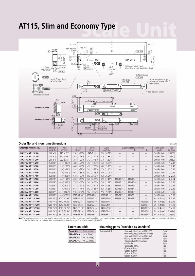
AT115, Slim and Economy Type
Mounting parts (provided as standard)Items included • Hex-socket head screw (M6x1x25)
• Hex-socket head screw (M4x0.7x25)• Hex-socket head screw (M4x0.7x8)• Spring washer (4mm nominal)• Plain washer (4mm nomina)• Cable clip• Connector clamp• Spacer (0.3mm)• Spacer (0.4mm)• Spacer (0.5mm)• Spacer (0.6mm)
2 pcs.2 pcs.6 pcs.2 pcs.2 pcs.5 pcs.1 pc.1 pc.1 pc.1 pc.1 pc.
Extension cableOrder No. Cable length09AAA674A 2m (6.5 feet)09AAA674B 5m (16.4 feet)09AAA674C 7m (22.9 feet)
Order No. and mounting dimensions mm (inch)
Order No. / Model No. Effectiverange L0
Travelrange L1
Mountinterval L2
Mountinterval L3
Overalllength L4
Supporting bracket position L5 L6 L7
Signal cablelength
Mass kg (lbs.)
539-271 / AT-115-100 100 (4”) 120 (4.72”) 258 (10.16”) 242 (9.53”) 276 (10.87”) — — — 3m (9.8 feet) 1.0 (2.2)539-272 / AT-115-150 150 (6”) 170 (6.69”) 308 (12.13”) 292 (11.50”) 326 (12.83”) — — — 3m (9.8 feet) 1.0 (2.2)539-273 / AT-115-200 200 (8”) 220 (8.66”) 358 (14.09”) 342 (13.46”) 376 (14.80”) — — — 3m (9.8 feet) 1.0 (2.2)539-274 / AT-115-250 250 (10”) 270 (10.63”) 408 (16.06”) 392 (15.43”) 426 (16.77”) — — — 3m (9.8 feet) 1.1 (2.42)539-275 / AT-115-300 300 (12”) 330 (12.99”) 468 (18.43”) 452 (17.80”) 486 (19.13”) — — — 3m (9.8 feet) 1.1 (2.42)539-276 / AT-115-350 350 (14”) 380 (14.96”) 518 (20.39”) 502 (19.76”) 536 (21.10”) — — — 3m (9.8 feet) 1.1 (2.42)539-277 / AT-115-400 400 (16”) 430 (16.93”) 568 (22.36”) 552 (21.73”) 586 (23.07”) — — — 3m (9.8 feet) 1.2 (2.64)539-278 / AT-115-450 450 (18”) 480 (18.90”) 618 (24.33”) 602 (23.70”) 636 (25.04”) — — — 3m (9.8 feet) 1.2 (2.64)539-279 / AT-115-500 500 (20”) 540 (21.26”) 678 (26.69”) 662 (26.06”) 696 (27.40”) 339 (13.35”) 331 (13.03”) — 3m (9.8 feet) 1.2 (2.64)539-281 / AT-115-600 600 (24”) 640 (25.20”) 778 (30.63”) 762 (30.00”) 796 (31.34”) 389 (15.31”) 381 (15.00”) — 3m (9.8 feet) 1.3 (2.86)539-283 / AT-115-700 700 (28”) 740 (29.13”) 878 (34.57”) 862 (33.94”) 896 (35.28”) 439 (17.28”) 431 (16.97”) — 3m (9.8 feet) 1.3 (2.86)539-284 / AT-115-750 750 (30”) 780 (30.71”) 918 (36.14”) 902 (35.51”) 936 (36.85”) 459 (18.07”) 451 (17.76”) — 3m (9.8 feet) 1.3 (2.86)539-285 / AT-115-800 800 (32”) 840 (33.07”) 978 (38.50”) 962 (37.87”) 996 (39.21”) 489 (19.25”) 481 (18.94”) — 3m (9.8 feet) 1.4 (3.08)539-286 / AT-115-900 900 (36”) 940 (37.01”) 1078 (42.44”) 1062 (41.81”) 1096 (43.15”) 539 (21.22”) 531 (20.91”) — 3m (9.8 feet) 1.4 (3.08)539-287 / AT-115-1000 1000 (40”) 1040 (40.94”) 1178 (46.38”) 1162 (45.75”) 1196 (47.09”) 589 (23.19”) 581 (22.87”) — 5m (16.4 feet) 1.8 (3.96)539-288 / AT-115-1100 1100 (44”) 1140 (44.88”) 1278 (50.31”) 1262 (49.69”) 1296 (51.02”) — — 430 (16.93”) 5m (16.4 feet) 1.8 (3.96)539-289 / AT-115-1200 1200 (48”) 1240 (48.82”) 1378 (54.25”) 1362 (53.62”) 1396 (54.96”) — — 460 (18.11”) 5m (16.4 feet) 1.9 (4.18)539-290 / AT-115-1300 1300 (52”) 1340 (52.76”) 1478 (58.19”) 1462 (57.56”) 1496 (58.90”) — — 490 (19.29”) 5m (16.4 feet) 1.9 (4.18)539-291 / AT-115-1400 1400 (56”) 1440 (56.69”) 1578 (62.13”) 1562 (61.50”) 1596 (62.83”) — — 530 (20.87”) 5m (16.4 feet) 2.0 (4.4)539-292 / AT-115-1500 1500 (60”) 1540 (60.63”) 1678 (66.06”) 1662 (65.43”) 1696 (66.77”) — — 560 (22.05”) 5m (16.4 feet) 2.0 (4.4)
Note) When selecting the size of a Linear Scale for your application, make sure that the maximum travel range of the Linear Scale (L1) is larger than the maximum travel range of the machine. Also, take into consideration in selecting a size that the accuracy of the Linear Scale is guaranteed only within the range of the effective measuring length (L0).
8
Ø10.
5(.4
13")
L1
15 (.
59")
9 (.35")
L2
6 (.24") 6 (.24")
Head cableLength: 0.3m (12")
Signal cableLength: 3m (9.8 feet)
Hole on both sides(5mm deep)
15.4 (.61")
15 (.60")
0.2±0.3(.008"±.012")
44.5
(1.7
52")
13 (.51"
)
8.4
(.331
")
56±0.2(2.21"±.008")
80 (3.15")
12(.47")
L0
4.4 (.17")
9 (.35")
25 (.98")
74±0.2(2.91"±.008")
M4x0.7 (x 2pcs.)
9 (.3
5")15
(.59
")0.
2 (.0
08") 3 (.12")
M6 through hole(x 2pcs.),Ø11mm hole on both sides (4.2mm deep)
G: Machine guide
25.5
±0.2
(1"±
.008
")
9 (.35")
30 (1
.18"
)
3 (.1
2")
1±0.
3(.0
4"±.
012"
)
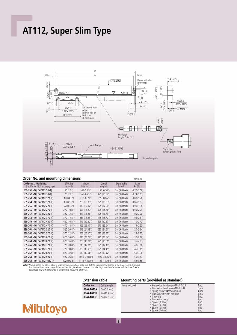
AT112, Super Slim Type
Mounting parts (provided as standard)Items included • Hex-socket head screw (M4x0.7x25)
• Hex-socket head screw (M4x0.7x8)• Spring washer (4mm nominal)• Plain washer (4mm nomina)• Cable clip• Connector clamp• Spacer (0.3mm)• Spacer (0.4mm)• Spacer (0.5mm)• Spacer (0.6mm)
4 pcs.6 pcs.4 pcs.4 pcs.5 pcs.1 pc.1 pc.1 pc.1 pc.1 pc.
Extension cableOrder No. Cable length09AAA033A 2m (6.5 feet)09AAA033B 5m (16.4 feet)09AAA033C 7m (22.9 feet)
Note) When selecting the size of a Linear Scale for your application, make sure that the maximum travel range of the Linear Scale (L1) is larger than the maximum travel range of the machine. Also, take into consideration in selecting a size that the accuracy of the Linear Scale is guaranteed only within the range of the effective measuring length (L0).
Order No. and mounting dimensions mm (inch)
Order No. / Model No.( ): suffix for high accuracy type
Effectiverange L0
Mountinterval L1
Overalllength L2
Signal cablelength
Masskg (lbs.)
539-251 (-10) / AT112-50 (F) 50 (2.0”) 143 (5.63”) 155 (6.10”) 3m (9.8 feet) 0.72 (1.58)539-252 (-10) / AT112-70 (F) 70 (2.8”) 163 (6.42”) 175 (10.89”) 3m (9.8 feet) 0.74 (1.63)539-253 (-10) / AT112-120 (F) 120 (4.8”) 213 (8.39”) 225 (8.86”) 3m (9.8 feet) 0.80 (1.76)539-254 (-10) / AT112-170 (F) 170 (6.8”) 263 (10.35”) 275 (10.83”) 3m (9.8 feet) 0.85 (1.87)539-255 (-10) / AT112-220 (F) 220 (8.8”) 313 (12.32”) 325 (12.80”) 3m (9.8 feet) 0.90 (1.98)539-256 (-10) / AT112-270 (F) 270 (10.8”) 363 (14.29”) 375 (14.76”) 3m (9.8 feet) 0.95 (2.09)539-257 (-10) / AT112-320 (F) 320 (12.8”) 413 (16.26”) 425 (16.73”) 3m (9.8 feet) 1.00 (2.20)539-258 (-10) / AT112-370 (F) 370 (14.8”) 463 (18.23”) 475 (18.70”) 3m (9.8 feet) 1.05 (2.31)539-259 (-10) / AT112-420 (F) 420 (16.8”) 513 (20.20”) 525 (20.67”) 3m (9.8 feet) 1.10 (2.42)539-260 (-10) / AT112-470 (F) 470 (18.8”) 563 (22.17”) 575 (22.64”) 3m (9.8 feet) 1.15 (2.53)539-261 (-10) / AT112-520 (F) 520 (20.8”) 613 (24.13”) 625 (24.61”) 3m (9.8 feet) 1.20 (2.64)539-262 (-10) / AT112-570 (F) 570 (22.8”) 663 (26.10”) 675 (26.57”) 3m (9.8 feet) 1.25 (2.75)539-263 (-10) / AT112-620 (F) 620 (24.8”) 713 (28.07”) 725 (28.54”) 3m (9.8 feet) 1.30 (2.86)539-264 (-10) / AT112-670 (F) 670 (26.8”) 763 (30.04”) 775 (30.51”) 3m (9.8 feet) 1.35 (2.97)539-265 (-10) / AT112-720 (F) 720 (28.8”) 813 (32.01”) 825 (32.48”) 3m (9.8 feet) 1.40 (3.08)539-266 (-10) / AT112-770 (F) 770 (30.8”) 863 (33.98”) 875 (34.45”) 3m (9.8 feet) 1.45 (3.19)539-267 (-10) / AT112-820 (F) 820 (32.8”) 913 (35.94”) 925 (36.42”) 3m (9.8 feet) 1.50 (3.30)539-268 (-10) / AT112-920 (F) 920 (36.8”) 1013 (39.88”) 1025 (40.35”) 3m (9.8 feet) 1.56 (3.43)539-269 (-10) / AT112-1020 (F) 1020 (40.8”) 1113 (43.82”) 1125 (44.29”) 3m (9.8 feet) 1.62 (3.56)
9
Scale Unit55
(2.1
7")
7.5
(.295
")
42 (1.65")
20 (.79")
11 (.43")
7 (.28") 28 (1.10")
70 (2
.76"
)
28 (1
.10"
)21
(.83
")
42 (1
.65"
)14 (.55"
)28
(1.1
0")
20(.79")
Ø16
(.63"
)
15 (.59")
L2
8 (.31")
L3Min. 0Max. L1
44(1
.73"
)13
(.51
")
9.5(.374")
24 (.94"
)
15 (.59")
35 (1
.38"
)
7.5 (.295") 7.5 (.295")10 (.39")
Min. 0Max. L0
21 (.83") 25 (.98")
Signal cable connector, Swievel angle: 260°
Mounting blockswievel angle: 360
M6 (x 2pcs.),10mm deep
Ø7mm through hole (x 3pcs.),Ø11mm hole (6.5mm deep)
Ø7mm through hole (x 2pcs.),Ø11mm hole (6.5mm deep)
M6 nut (x 2pcs.) in T-groove(8mm deep)
M6 nut (x 2pcs.)in T-groove (8mm deep)
Signal cable, Length: 3m (9.8 feet)
G: Machine guide
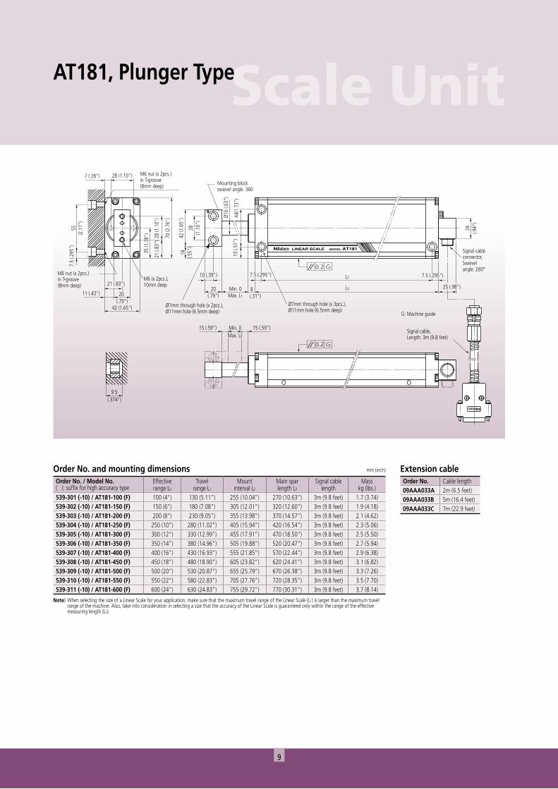
AT181, Plunger Type
Order No. and mounting dimensions mm (inch)
Order No. / Model No.( ): suffix for high accuracy type
Effectiverange L0
Travelrange L1
Mountinterval L2
Main sparlength L3
Signal cablelength
Masskg (lbs.)
539-301 (-10) / AT181-100 (F) 100 (4”) 130 (5.11”) 255 (10.04”) 270 (10.63”) 3m (9.8 feet) 1.7 (3.74)539-302 (-10) / AT181-150 (F) 150 (6”) 180 (7.08”) 305 (12.01”) 320 (12.60”) 3m (9.8 feet) 1.9 (4.18)539-303 (-10) / AT181-200 (F) 200 (8”) 230 (9.05”) 355 (13.98”) 370 (14.57”) 3m (9.8 feet) 2.1 (4.62)539-304 (-10) / AT181-250 (F) 250 (10”) 280 (11.02”) 405 (15.94”) 420 (16.54”) 3m (9.8 feet) 2.3 (5.06)539-305 (-10) / AT181-300 (F) 300 (12”) 330 (12.99”) 455 (17.91”) 470 (18.50”) 3m (9.8 feet) 2.5 (5.50)539-306 (-10) / AT181-350 (F) 350 (14”) 380 (14.96”) 505 (19.88”) 520 (20.47”) 3m (9.8 feet) 2.7 (5.94)539-307 (-10) / AT181-400 (F) 400 (16”) 430 (16.93”) 555 (21.85”) 570 (22.44”) 3m (9.8 feet) 2.9 (6.38)539-308 (-10) / AT181-450 (F) 450 (18”) 480 (18.90”) 605 (23.82”) 620 (24.41”) 3m (9.8 feet) 3.1 (6.82)539-309 (-10) / AT181-500 (F) 500 (20”) 530 (20.87”) 655 (25.79”) 670 (26.38”) 3m (9.8 feet) 3.3 (7.26)539-310 (-10) / AT181-550 (F) 550 (22”) 580 (22.83”) 705 (27.76”) 720 (28.35”) 3m (9.8 feet) 3.5 (7.70)539-311 (-10) / AT181-600 (F) 600 (24”) 630 (24.83”) 755 (29.72”) 770 (30.31”) 3m (9.8 feet) 3.7 (8.14)
Note) When selecting the size of a Linear Scale for your application, make sure that the maximum travel range of the Linear Scale (L1) is larger than the maximum travel range of the machine. Also, take into consideration in selecting a size that the accuracy of the Linear Scale is guaranteed only within the range of the effective measuring length (L0).
Extension cableOrder No. Cable length09AAA033A 2m (6.5 feet)09AAA033B 5m (16.4 feet)09AAA033C 7m (22.9 feet)
10
SERIALNo.E3000001
MADE IN JAPAN
AT715E3000001No.SERIAL
5
70
5
1
4.5
9
Middle support position L8
Middle support position L7
15.5
Middle support position L6
12±0
.2
10 50±0.2
Middle support position L8
Middle support position L7
13
12
51
23.2
Middle support position L5
5
25.7
50±0.2φ9
60
41
18
Mounting hole pitch L2
Total length L4
Effective length L0
Max. travel length L1
101219
714
17.5
0.3
Mounting hole pitch L3
2-R2.5
2-R2.5
adjustableMiddle support : see Mouting method A
signal cable
B
B'
C
C'
adjustableMiddle Support : see Mounting method C
adjustable
2-M4 depth 5
G: Machine guide
Mounting method A
(1.5)19
0.7
1
1
1
1
53.7(54.7)
53.7
(54.7)
54(54.7)
16
(54)36
.5
1.5±0.2
22
1.5
A
C-C' Sectional dimension
C-C' Sectional dimension
B-B' Sectional dimension
Mounting method B
Middle support (V)adjustable
Mounting method C
Mounting method B,C
Middle support (V)adjustable
Block spacer
2-φ7φ14 Countersunk, depth 6.5
Middle support : see Mounting method B
24
Countersunk, depth 6.5
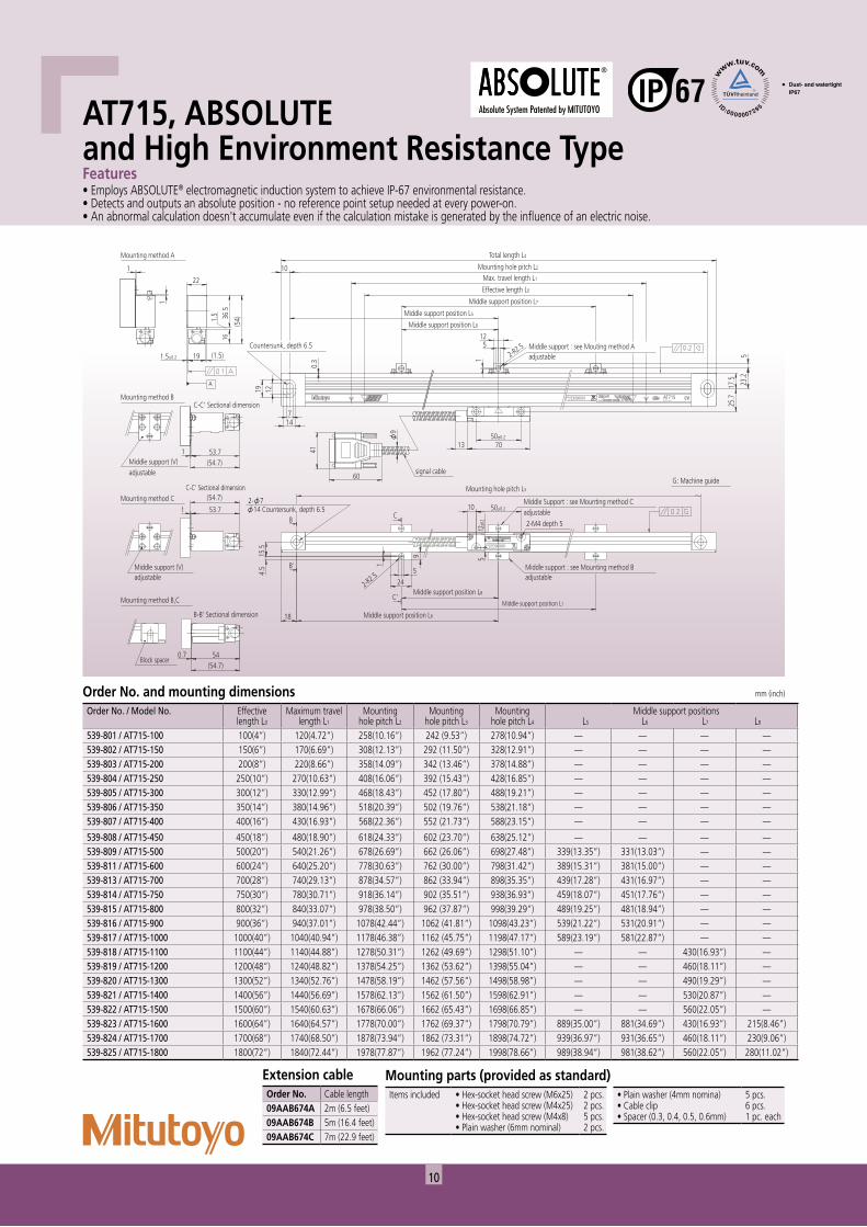
AT715, ABSOLUTE and High Environment Resistance TypeFeatures• Employs ABSOLUTE® electromagnetic induction system to achieve IP-67 environmental resistance.• Detects and outputs an absolute position - no reference point setup needed at every power-on.• An abnormal calculation doesn't accumulate even if the calculation mistake is generated by the influence of an electric noise.
Extension cableOrder No. Cable length09AAB674A 2m (6.5 feet)09AAB674B 5m (16.4 feet)09AAB674C 7m (22.9 feet)
Mounting parts (provided as standard)Items included • Hex-socket head screw (M6x25)
• Hex-socket head screw (M4x25)• Hex-socket head screw (M4x8)• Plain washer (6mm nominal)
2 pcs.2 pcs.5 pcs.2 pcs.
• Plain washer (4mm nomina)• Cable clip• Spacer (0.3, 0.4, 0.5, 0.6mm)
5 pcs.6 pcs.1 pc. each
Order No. and mounting dimensions mm (inch)
Order No. / Model No. Effectivelength L0
Maximum travellength L1
Mountinghole pitch L2
Mountinghole pitch L3
Mountinghole pitch L4
Middle support positionsL5 L6 L7 L8
539-801 / AT715-100 100(4”) 120(4.72”) 258(10.16”) 242 (9.53”) 278(10.94”) — — — —539-802 / AT715-150 150(6”) 170(6.69”) 308(12.13”) 292 (11.50”) 328(12.91”) — — — —539-803 / AT715-200 200(8”) 220(8.66”) 358(14.09”) 342 (13.46”) 378(14.88”) — — — —539-804 / AT715-250 250(10”) 270(10.63”) 408(16.06”) 392 (15.43”) 428(16.85”) — — — —539-805 / AT715-300 300(12”) 330(12.99”) 468(18.43”) 452 (17.80”) 488(19.21”) — — — —539-806 / AT715-350 350(14”) 380(14.96”) 518(20.39”) 502 (19.76”) 538(21.18”) — — — —539-807 / AT715-400 400(16”) 430(16.93”) 568(22.36”) 552 (21.73”) 588(23.15”) — — — —
539-808 / AT715-450 450(18”) 480(18.90”) 618(24.33”) 602 (23.70”) 638(25.12”) — — — —539-809 / AT715-500 500(20”) 540(21.26”) 678(26.69”) 662 (26.06”) 698(27.48”) 339(13.35”) 331(13.03”) — —539-811 / AT715-600 600(24”) 640(25.20”) 778(30.63”) 762 (30.00”) 798(31.42”) 389(15.31”) 381(15.00”) — —539-813 / AT715-700 700(28”) 740(29.13”) 878(34.57”) 862 (33.94”) 898(35.35”) 439(17.28”) 431(16.97”) — —539-814 / AT715-750 750(30”) 780(30.71”) 918(36.14”) 902 (35.51”) 938(36.93”) 459(18.07”) 451(17.76”) — —539-815 / AT715-800 800(32”) 840(33.07”) 978(38.50”) 962 (37.87”) 998(39.29”) 489(19.25”) 481(18.94”) — —539-816 / AT715-900 900(36”) 940(37.01”) 1078(42.44”) 1062 (41.81”) 1098(43.23”) 539(21.22”) 531(20.91”) — —539-817 / AT715-1000 1000(40”) 1040(40.94”) 1178(46.38”) 1162 (45.75”) 1198(47.17”) 589(23.19”) 581(22.87”) — —539-818 / AT715-1100 1100(44”) 1140(44.88”) 1278(50.31”) 1262 (49.69”) 1298(51.10”) — — 430(16.93”) —539-819 / AT715-1200 1200(48”) 1240(48.82”) 1378(54.25”) 1362 (53.62”) 1398(55.04”) — — 460(18.11”) —539-820 / AT715-1300 1300(52”) 1340(52.76”) 1478(58.19”) 1462 (57.56”) 1498(58.98”) — — 490(19.29”) —539-821 / AT715-1400 1400(56”) 1440(56.69”) 1578(62.13”) 1562 (61.50”) 1598(62.91”) — — 530(20.87”) —539-822 / AT715-1500 1500(60”) 1540(60.63”) 1678(66.06”) 1662 (65.43”) 1698(66.85”) — — 560(22.05”) —539-823 / AT715-1600 1600(64”) 1640(64.57”) 1778(70.00”) 1762 (69.37”) 1798(70.79”) 889(35.00”) 881(34.69”) 430(16.93”) 215(8.46”)539-824 / AT715-1700 1700(68”) 1740(68.50”) 1878(73.94”) 1862 (73.31”) 1898(74.72”) 939(36.97”) 931(36.65”) 460(18.11”) 230(9.06”)539-825 / AT715-1800 1800(72”) 1840(72.44”) 1978(77.87”) 1962 (77.24”) 1998(78.66”) 989(38.94”) 981(38.62”) 560(22.05”) 280(11.02”)
11
Scale Unit
Index scale
Main scale
Phototransister
LED
Scale reference point mark
20µm
Phase difference of 90˚
20±10µm
VDC 2.5V Vp
p 2V
Phase A
Phase B
Scale referencepoint signal
Indu
ced
volta
ge V
λ1
λ2
VlaVla
V2aV2b
X bX a Position X
Second scale
First scale
Slider Second exciting coil
First exciting coil
Second detecting coilFirst detecting coil
λ1λ2
Scale
First scale
Second scale
Second scale
Sensor
Joint bar
Spring
Detector head
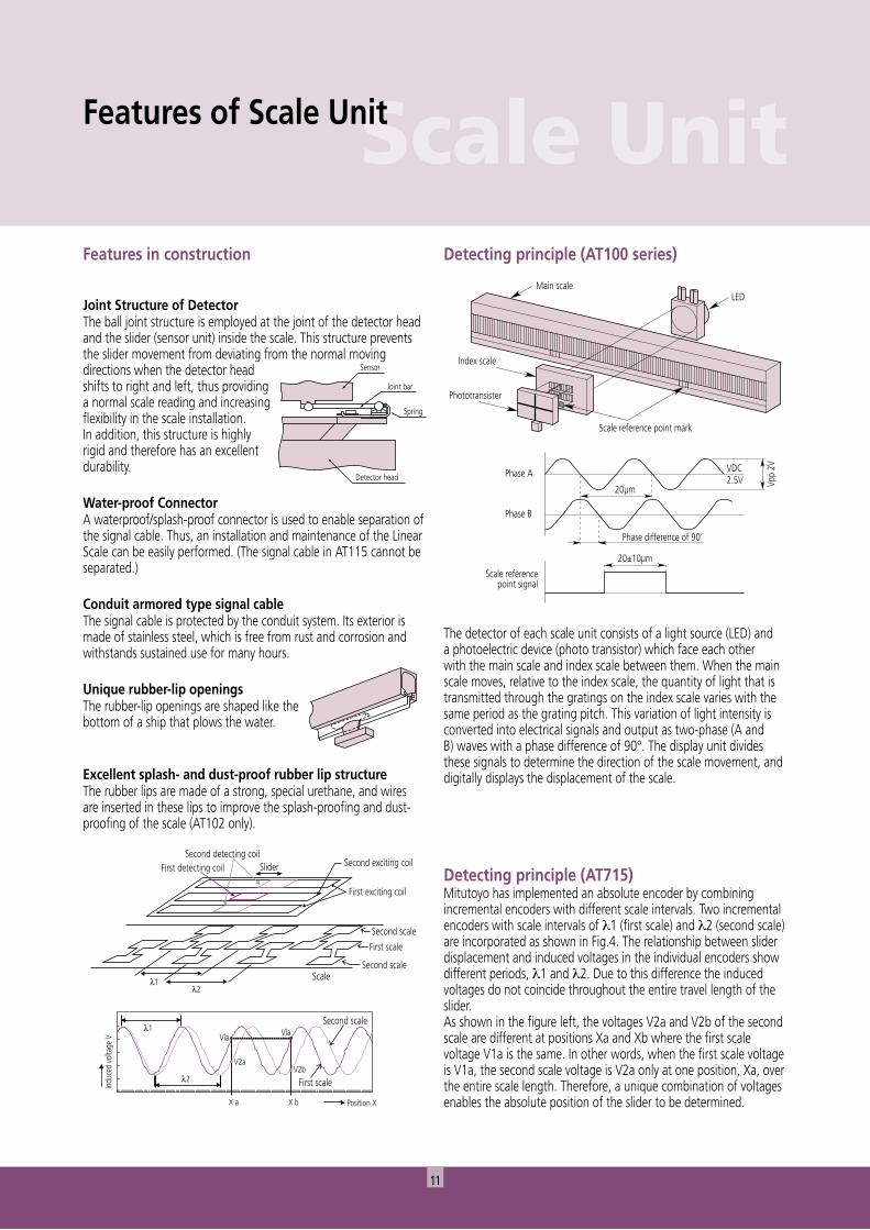
Detecting principle (AT100 series)
The detector of each scale unit consists of a light source (LED) and a photoelectric device (photo transistor) which face each other with the main scale and index scale between them. When the main scale moves, relative to the index scale, the quantity of light that is transmitted through the gratings on the index scale varies with the same period as the grating pitch. This variation of light intensity is converted into electrical signals and output as two-phase (A and B) waves with a phase difference of 90°. The display unit divides these signals to determine the direction of the scale movement, and digitally displays the displacement of the scale.
Features of Scale Unit
Detecting principle (AT715)Mitutoyo has implemented an absolute encoder by combining incremental encoders with different scale intervals. Two incremental encoders with scale intervals of λ1 (first scale) and λ2 (second scale) are incorporated as shown in Fig.4. The relationship between slider displacement and induced voltages in the individual encoders show different periods, λ1 and λ2. Due to this difference the induced voltages do not coincide throughout the entire travel length of the slider. As shown in the figure left, the voltages V2a and V2b of the second scale are different at positions Xa and Xb where the first scale voltage V1a is the same. In other words, when the first scale voltage is V1a, the second scale voltage is V2a only at one position, Xa, over the entire scale length. Therefore, a unique combination of voltages enables the absolute position of the slider to be determined.
Features in construction
Joint Structure of DetectorThe ball joint structure is employed at the joint of the detector head and the slider (sensor unit) inside the scale. This structure prevents the slider movement from deviating from the normal moving directions when the detector head shifts to right and left, thus providing a normal scale reading and increasing flexibility in the scale installation. In addition, this structure is highly rigid and therefore has an excellent durability.
Water-proof ConnectorA waterproof/splash-proof connector is used to enable separation of the signal cable. Thus, an installation and maintenance of the Linear Scale can be easily performed. (The signal cable in AT115 cannot be separated.)
Conduit armored type signal cableThe signal cable is protected by the conduit system. Its exterior is made of stainless steel, which is free from rust and corrosion and withstands sustained use for many hours.
Unique rubber-lip openingsThe rubber-lip openings are shaped like the bottom of a ship that plows the water.
Excellent splash- and dust-proof rubber lip structureThe rubber lips are made of a strong, special urethane, and wires are inserted in these lips to improve the splash-proofing and dust-proofing of the scale (AT102 only).
12
AT102
When using an optional extension cable
Optional extension cable Signal cable
Cable length: 2m / 5m / 7m
Cable length: 2m / 5m / 7m
Cable length: 2m / 5m / 7m
Cable length: 2m / 5m / 7m
Cable length: 2m / 5m / 7m
AT113
AT115
AT112
AT181
AT715
AT102
AT113
AT115
AT112
AT181
AT715
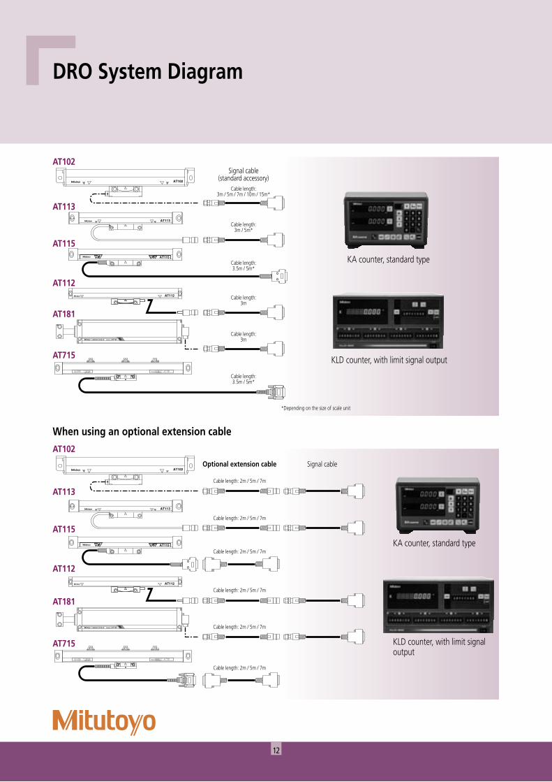
Signal cable(standard accessory)
Cable length:3m / 5m / 7m / 10m / 15m*
Cable length:3m / 5m*
Cable length:3.5m / 5m*
Cable length:3m
Cable length:3m
Cable length:3.5m / 5m*
*Depending on the size of scale unit
Cable length: 2m / 5m / 7m
DRO System Diagram
KA counter, standard type
KLD counter, with limit signal output
KA counter, standard type
KLD counter, with limit signal output
13
Display UnitDisplay Unit Selection Guide
Counter
Function
KA Counter KLD Counter
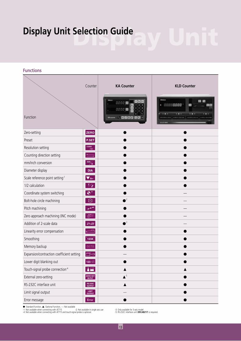
Zero-setting ● ●
Preset ● ●
Resolution setting ● ●
Counting direction setting ● ●
mm/inch conversion ● ●
Diameter display ● ●
Scale reference point setting-1 ● ●
1/2 calculation ● ●
Coordinate system switching ● —
Bolt-hole circle machining ●-2 —
Pitch machining ● —
Zero approach machining (INC mode) ● —
Addition of 2-scale data ●-3 —
Linearity error compensation ● ●
Smoothing ● ●
Memory backup ● ●
Expansion/contraction coefficient setting — ●
Lower digit blanking out ● ●
Touch-signal probe connection-4 ▲ ▲
External zero-setting ▲-5
●
RS-232C interface unit ▲ ●
Limit signal output — ●
Error message ● ●
Functions
●: Standard function, ▲: Optional function, —: Not available-1: Not available when connecting with AT715 -2: Not available in single axis use -3: Only available for 3-axis model -4: Not available when connecting with AT715 and touch-signal probe is optional. -5: RS-232C interface unit (09CAB217) is required.
14
260
206
80
167
43(1
)
Mount screw x2 (M5)
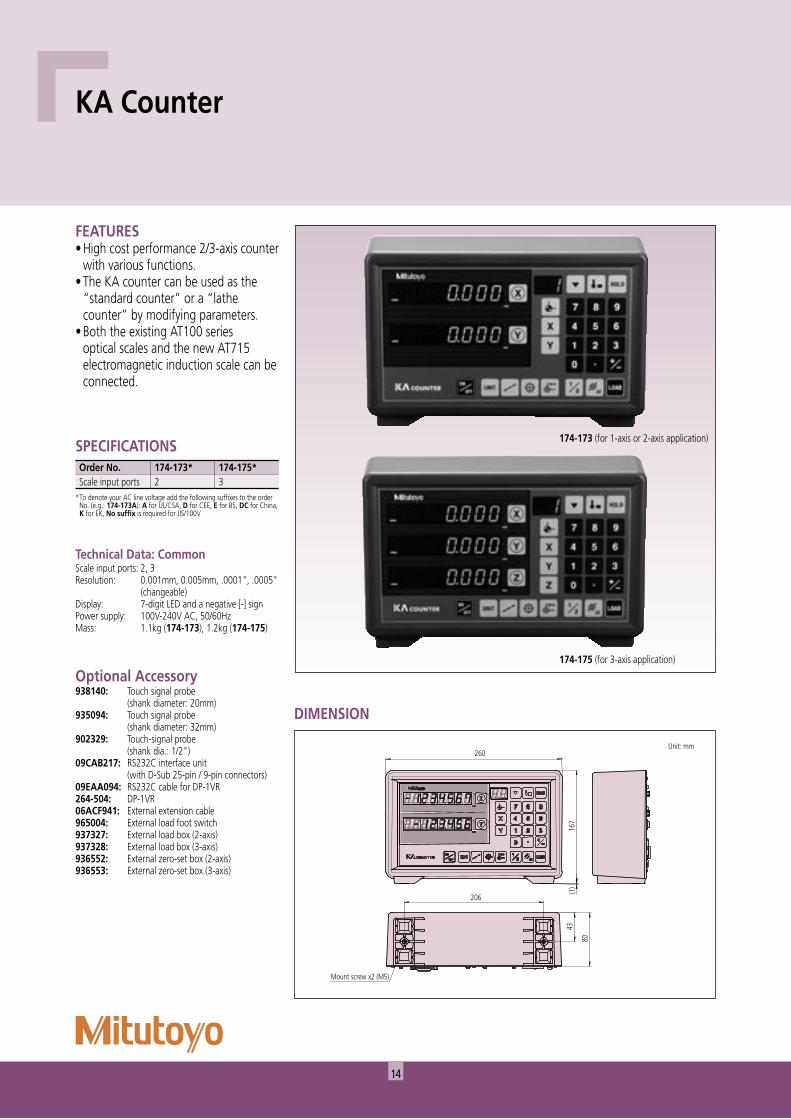
Technical Data: CommonScale input ports: 2, 3Resolution: 0.001mm, 0.005mm, .0001", .0005" (changeable)Display: 7-digit LED and a negative [-] signPower supply: 100V-240V AC, 50/60HzMass: 1.1kg (174-173), 1.2kg (174-175)
FEATURES• High cost performance 2/3-axis counter
with various functions.• The KA counter can be used as the
“standard counter” or a “lathe counter” by modifying parameters.
• Both the existing AT100 series optical scales and the new AT715 electromagnetic induction scale can be connected.
Optional Accessory938140: Touch signal probe (shank diameter: 20mm)935094: Touch signal probe (shank diameter: 32mm)902329: Touch-signal probe (shank dia.: 1/2")09CAB217: RS232C interface unit (with D-Sub 25-pin / 9-pin connectors)09EAA094: RS232C cable for DP-1VR264-504: DP-1VR06ACF941: External extension cable965004: External load foot switch937327: External load box (2-axis)937328: External load box (3-axis)936552: External zero-set box (2-axis)936553: External zero-set box (3-axis)
DIMENSION
174-173 (for 1-axis or 2-axis application)SPECIFICATIONSOrder No. 174-173* 174-175*Scale input ports 2 3
* To denote your AC line voltage add the following suffixes to the order No. (e.g.: 174-173A): A for UL/CSA, D for CEE, E for BS, DC for China, K for EK, No suffix is required for JIS/100V
174-175 (for 3-axis application)
KA Counter
Unit: mm
15
Display Unit
332 204
163
1 A 2 B 3 C 4 5D
KLD200
00000 0 0
000 0 0 0 000000 0 0000 0 0 0 00000- 0 0 0 - - -
-
1/2
LOAD
HOLDSETZEROmmE
1 2 3 4 5 6 7
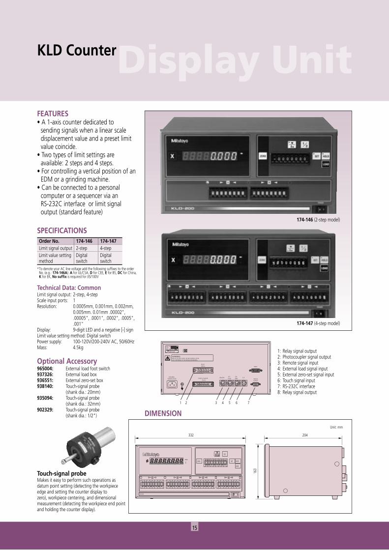
Touch-signal probeMakes it easy to perform such operations as datum point setting (detecting the workpiece edge and setting the counter display to zero), workpiece centering, and dimensional measurement (detecting the workpiece end point and holding the counter display).
FEATURES• A 1-axis counter dedicated to
sending signals when a linear scale displacement value and a preset limit value coincide.
• Two types of limit settings are available: 2 steps and 4 steps.
• For controlling a vertical position of an EDM or a grinding machine.
• Can be connected to a personal computer or a sequencer via an
RS-232C interface or limit signal output (standard feature)
Optional Accessory965004: External load foot switch937326: External load box936551: External zero-set box938140: Touch-signal probe (shank dia.: 20mm)935094: Touch-signal probe (shank dia.: 32mm)902329: Touch-signal probe (shank dia.: 1/2") DIMENSION
Unit: mm
KLD Counter
SPECIFICATIONSOrder No. 174-146 174-147Limit signal output 2-step 4-stepLimit value setting method
Digital switch
Digital switch
* To denote your AC line voltage add the following suffixes to the order No. (e.g.: 174-146A): A for UL/CSA, D for CEE, E for BS, DC for China, K for EK, No suffix is required for JIS/100V
Technical Data: CommonLimit signal output: 2-step, 4-stepScale input ports: 1Resolution: 0.0005mm, 0.001mm, 0.002mm, 0.005mm. 0.01mm .00002", .00005", .0001", .0002", .0005", .001"Display: 9-digit LED and a negative [-] signLimit value setting method: Digital switchPower supply: 100-120V/200-240V AC, 50/60HzMass: 4.5kg
174-146 (2-step model)
174-147 (4-step model)
1: Relay signal output2: Photocoupler signal output3: Remote signal input4: External load signal input5: External zero-set signal input6: Touch signal input7: RS-232C interface8: Relay signal output
16
Workpiece
0 0 0
12.34512.34512.345Workpiece
12.345preset
12.345preset
12.345preset
Counts down
0
0
0
Detector unit fixedForward direction: Counts up as the main spar moves right.
Reverse direction: Counts up as the main spar moves left.
20 10 10 40
Counts up
Datum plane(Zero set)
0 0 0 Recall
80Zero set
WorkpieceMchiningtool
40
100
11 12 12 12 12
0 30 45Machining using absolute coordinate:
Datum point
Machining using incremental coordinate:
L
eθ
θ
Machine table
SPECIAL FUNCTIONS
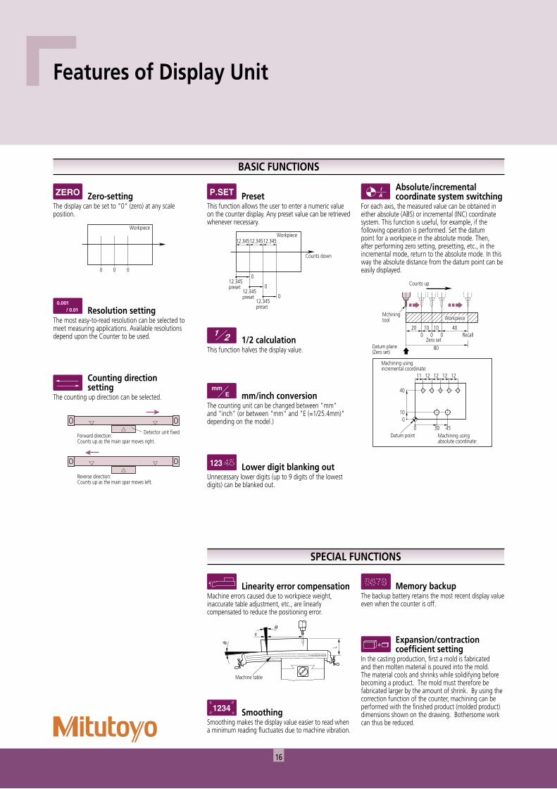
Expansion/contraction coefficient setting
In the casting production, first a mold is fabricated and then molten material is poured into the mold. The material cools and shrinks while solidifying before becoming a product. The mold must therefore be fabricated larger by the amount of shrink. By using the correction function of the counter, machining can be performed with the finished product (molded product) dimensions shown on the drawing. Bothersome work can thus be reduced.
Memory backupThe backup battery retains the most recent display value even when the counter is off.
Lower digit blanking outUnnecessary lower digits (up to 9 digits of the lowest digits) can be blanked out.
Absolute/incremental coordinate system switching
For each axis, the measured value can be obtained in either absolute (ABS) or incremental (INC) coordinate system. This function is useful, for example, if the following operation is performed. Set the datum point for a workpiece in the absolute mode. Then, after performing zero setting, presetting, etc., in the incremental mode, return to the absolute mode. In this way the absolute distance from the datum point can be easily displayed.
1/2 calculationThis function halves the display value.
mm/inch conversionThe counting unit can be changed between "mm" and "inch" (or between "mm" and "E (=1/25.4mm)" depending on the model.)
Counting direction setting
The counting up direction can be selected.
Resolution settingThe most easy-to-read resolution can be selected to meet measuring applications. Available resolutions depend upon the Counter to be used.
PresetThis function allows the user to enter a numeric value on the counter display. Any preset value can be retrieved whenever necessary.
Zero-settingThe display can be set to "0" (zero) at any scale position.
SmoothingSmoothing makes the display value easier to read when a minimum reading fluctuates due to machine vibration.
Linearity error compensationMachine errors caused due to workpiece weight, inaccurate table adjustment, etc., are linearly compensated to reduce the positioning error.
Features of Display Unit
BASIC FUNCTIONS
17
Display Unit
Countsup
8 10
0 0
8 10
20 10 20 10
60
4321
1234
Up to 5 tools can be registered on the KM/KC Counter.Up to 10 tools can be registered on the KLL Counter.
Tool (1)
Tool (2)
Tool (3)
Tool (4)
Touch signal probe
Counts up
Datum plane (0)
Offset value Workpiece
Machine table
1 23
4
5
Workpiece
Touch signal probe
Datum plane
Workpiece
Machine table
X
0Scale reference point
Start point (x, y)
Evenly divide by n
End point (x, y)
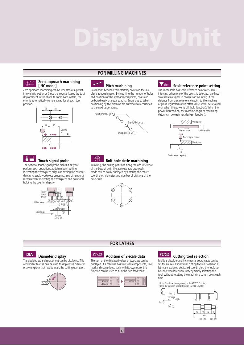
Zero approach machining [INC mode]
Zero approach machining can be repeated at a preset interval without error. Since the counter keeps the total displacement in the absolute coordinate system, the error is automatically compensated for at each tool position.
Diameter displayThe doubled scale displacement can be displayed. This convenient feature can be used to display the diameter of a workpiece that results in a lathe cutting operation.
Bolt-hole circle machiningIn milling, the drilling positions along the circumference of the base circle in the absolute zero approach mode can be easily displayed by entering the center coordinates, diameter, and number of divisions of the base circle.
Touch-signal probeThe optional touch-signal probe makes it easy to perform such operations as datum point setting (detecting the workpiece edge and setting the counter display to zero), workpiece centering, and dimensional measurement (detecting the workpiece end point and holding the counter display).
Cutting tool selectionMultiple absolute and incremental coordinates can be set for an axis. If individual cutting tools installed on a lathe are assigned dedicated coordinates, the tools can be used whenever necessary by simply selecting the tool, without resetting the machining datum point each time.
Scale reference point settingThe linear scale has scale reference points at 50mm intervals. When one of the points is detected, the linear scale issues a signal to hold/restart counting. If the distance from a scale reference point to the machine origin is registered as the offset value, it will be retained even when the power is off (hold function). When the power is turned on, the machine origin or machining datum can be easily recalled (set function).
Addition of 2-scale dataThe sum of the displayed values of two axes can be displayed. If a machine has two feed components, fine feed and coarse feed, each with its own scale, this function can be used to sum the two feed values.
Pitch machiningBores holes between two arbitrary points on the X-Y plane at equal spaces. By inputting the number of holes and positions of the start and end points, holes can be bored easily at equal spacing. Errors due to table positioning by the machine are automatically corrected to the next target value.
FOR LATHES
FOR MILLING MACHINES
18
X + 0 0 0 0 0 0 0 0 CR LF.
X + 1 2 3 4 5 6 7 8 CR LF.
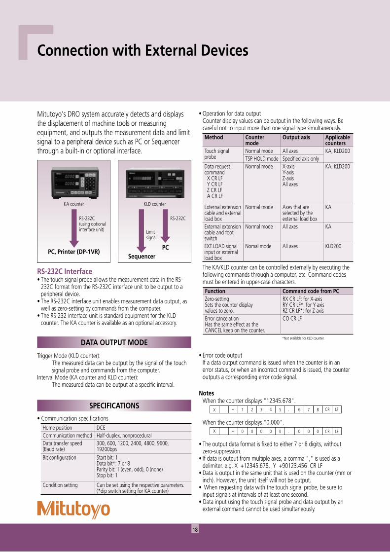
Mitutoyo's DRO system accurately detects and displays the displacement of machine tools or measuring equipment, and outputs the measurement data and limit signal to a peripheral device such as PC or Sequencer through a built-in or optional interface.
RS-232C Interface• The touch signal probe allows the measurement data in the RS-
232C format from the RS-232C interface unit to be output to a peripheral device.
• The RS-232C interface unit enables measurement data output, as well as zero-setting by commands from the computer.
• The RS-232 interface unit is standard equipment for the KLD counter. The KA counter is available as an optional accessory.
Trigger Mode (KLD counter): The measured data can be output by the signal of the touch signal probe and commands from the computer.
Interval Mode (KA counter and KLD counter): The measured data can be output at a specific interval.
DATA OUTPUT MODE
Connection with External Devices
• Communication specificationsHome position DCECommunication method Half-duplex, nonproceduralData transfer speed(Baud rate)
300, 600, 1200, 2400, 4800, 9600, 19200bps
Bit configuration Start bit: 1Data bit*: 7 or 8Parity bit: 1 (even, odd), 0 (none)Stop bit: 1
Condition setting Can be set using the respective parameters. (*dip switch setting for KA counter)
• Operation for data output Counter display values can be output in the following ways. Be
careful not to input more than one signal type simultaneously.Method Counter
modeOutput axis Applicable
countersTouch signalprobe
Normal mode All axes KA, KLD200TSP HOLD mode Specified axis only
Data request command X CR LF Y CR LF Z CR LF A CR LF
Normal mode X-axisY-axisZ-axisAll axes
KA, KLD200
External extensioncable and externalload box
Normal mode Axes that are selected by the external load box
KA
External extensioncable and footswitch
Normal mode All axes KA
EXT.LOAD signalinput or externalload box
Nomal mode All axes KLD200
The KA/KLD counter can be controlled externally by executing the following commands through a computer, etc. Command codes must be entered in upper-case characters.Function Command code from PCZero-settingSets the counter display values to zero.
RX CR LF: for X-axisRY CR LF*: for Y-axisRZ CR LF*: for Z-axis
Error cancelationHas the same effect as the CANCEL keep on the counter.
CO CR LF
*Not available for KLD counter.
RS-232C(using optionalinterface unit)
PC, Printer (DP-1VR)
RS-232C
PC
Limitsignal
Sequencer
KA counter KLD counter
• Error code output If a data output command is issued when the counter is in an
error status, or when an incorrect command is issued, the counter outputs a corresponding error code signal.
Notes When the counter displays "12345.678".
When the counter displays "0.000".
• The output data format is fixed to either 7 or 8 digits, without zero-suppression.
• If data is output from multiple axes, a comma "," is used as a delimiter. e.g. X +12345.678, Y +90123.456 CR LF
• Data is output in the same unit that is used on the counter (mm or inch). However, the unit itself will not be output.
• When requesting data with the touch signal probe, be sure to input signals at intervals of at least one second.
• Data input using the touch signal probe and data output by an external command cannot be used simultaneously.
SPECIFICATIONS
19
Data Output
13
25 14
1
1 5
6 9
50
1000 + 50
25
200 + 20
D-Sub 9-pin
A
DP-1VR
C
B
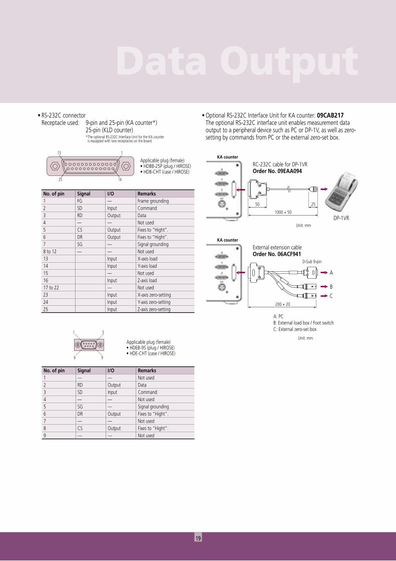
A: PCB: External load box / Foot switchC: External zero-set box
RC-232C cable for DP-1VROrder No. 09EAA094
External extension cableOrder No. 06ACF941
KA counter
KA counter
Unit: mm
Unit: mm
• RS-232C connector Receptacle used: 9-pin and 25-pin (KA counter*)
25-pin (KLD counter)* The optional RS-232C Interface Unit for the KA counter is equipped with two receptacles on the board.
No. of pin Signal I/O Remarks1 FG — Frame grounding2 SD Input Command3 RD Output Data4 — — Not used5 CS Output Fixes to “Hight”.6 DR Output Fixes to “Hight”.7 SG — Signal grounding8 to 12 — — Not used13 Input X-axis load14 Input Y-axis load15 — Not used16 Input Z-axis load17 to 22 — Not used23 Input X-axis zero-setting24 Input Y-axis zero-setting25 Input Z-axis zero-setting
Applicable plug (female)• HDBB-25P (plug / HIROSE)• HDB-CHT (case / HIROSE)
Applicable plug (female)• HDEB-9S (plug / HIROSE)• HDE-CHT (case / HIROSE)
No. of pin Signal I/O Remarks1 — — Not used2 RD Output Data3 SD Input Command4 — — Not used5 SG — Signal grounding6 DR Output Fixes to “Hight”.7 — — Not used8 CS Output Fixes to “Hight”.9 — — Not used
• Optional RS-232C Interface Unit for KA counter: 09CAB217 The optional RS-232C interface unit enables measurement data output to a peripheral device such as PC or DP-1V, as well as zero-setting by commands from PC or the external zero-set box.
Connection with External Devices
20
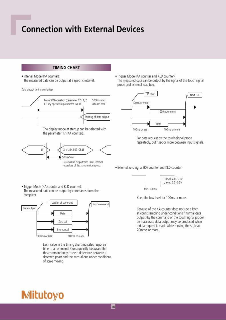
Data output timing on startup
Starting of data output
Power ON operation (parameter 17): 1, 2 5000ms maxCE key operation (parameter 17): 0 2000ms max
LF
50ms±5ms
Data will be output with 50ms interval regardless of the transmission speed.
X +1234.567 CR LF
Data outputNext commandLast bit of command
Data
Zero set
Error cancel
100ms or less 100ms or more
Next TSPTSP input
Data
100ms or less 100ms or more
1000ms or more
100ms or more
Min. 100ms
H level: 4.0 - 5.0VL level: 0.0 - 0.5V
TIMING CHART
• Trigger Mode (KA counter and KLD counter): The measured data can be output by commands from the computer.
• Interval Mode (KA counter): The measured data can be output at a specific interval.
The display mode at startup can be selected with the parameter 17 (KA counter).
For data request by the touch-signal probe repeatedly, put 1sec or more between input signals.
• Trigger Mode (KA counter and KLD counter): The measured data can be output by the signal of the touch signal probe and external load box.
• External zero signal (KA counter and KLD counter)
Keep the low level for 100ms or more.
Each value in the timing chart indicates response time to a command. Consequently, be aware that this command may cause a difference between a detected point and the accrual one under conditions of scale moving.
Because of the KA counter does not use a latch at count sampling under conditions f normal data output (by the command or the touch signal probe), an inaccurate data output may be produced when a data request is made while moving the scale at 70mm/s or more.
21
Data Output
Motor
Surge absorber
DSP1-DC5V
Connection example
Relay
Relay
Circuit inside the counter
Varistor
COMMON
ba
Z ZZ
1 to 7mA Resistance
Photocoupler TLP521-4
Circuit inside the counter5V to 30V
Connection example
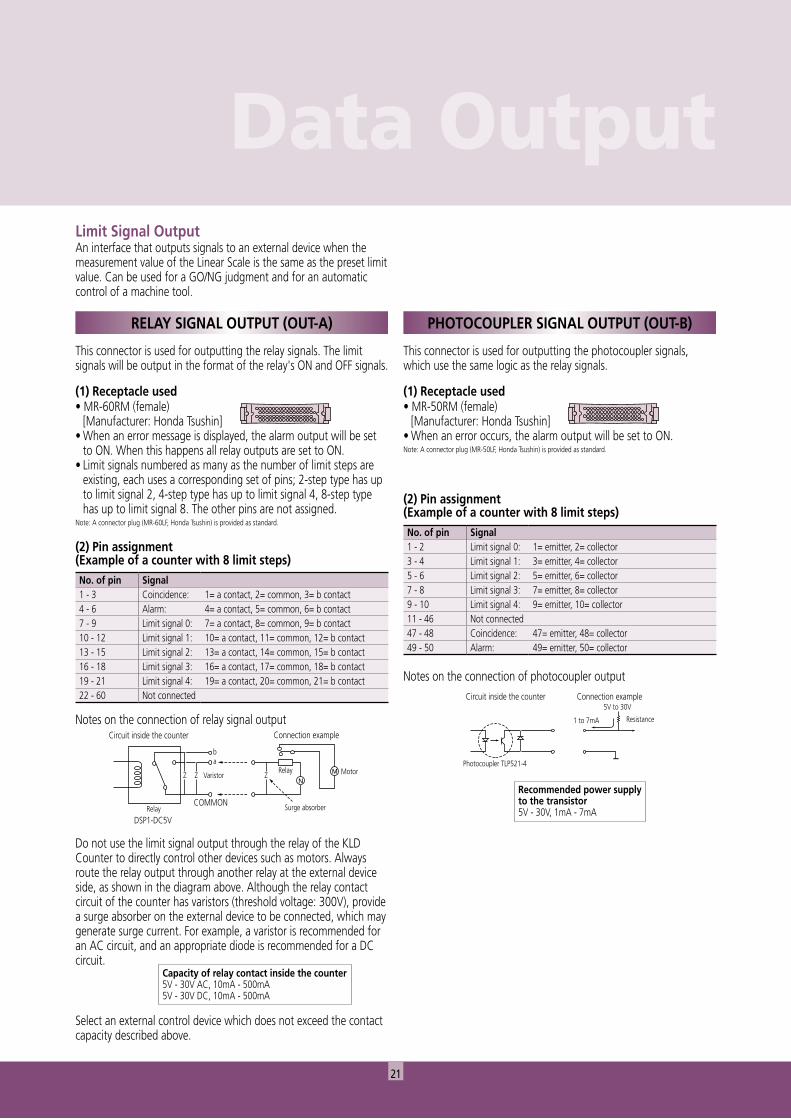
Notes on the connection of relay signal output
Do not use the limit signal output through the relay of the KLD Counter to directly control other devices such as motors. Always route the relay output through another relay at the external device side, as shown in the diagram above. Although the relay contact circuit of the counter has varistors (threshold voltage: 300V), provide a surge absorber on the external device to be connected, which may generate surge current. For example, a varistor is recommended for an AC circuit, and an appropriate diode is recommended for a DC circuit.
Select an external control device which does not exceed the contact capacity described above.
This connector is used for outputting the photocoupler signals, which use the same logic as the relay signals.
(1) Receptacle used• MR-50RM (female)
[Manufacturer: Honda Tsushin]• When an error occurs, the alarm output will be set to ON.Note: A connector plug (MR-50LF, Honda Tsushin) is provided as standard.
Notes on the connection of photocoupler output
Recommended power supply to the transistor5V - 30V, 1mA - 7mA
(2) Pin assignment (Example of a counter with 8 limit steps)No. of pin Signal1 - 3 Coincidence: 1= a contact, 2= common, 3= b contact4 - 6 Alarm: 4= a contact, 5= common, 6= b contact7 - 9 Limit signal 0: 7= a contact, 8= common, 9= b contact10 - 12 Limit signal 1: 10= a contact, 11= common, 12= b contact13 - 15 Limit signal 2: 13= a contact, 14= common, 15= b contact16 - 18 Limit signal 3: 16= a contact, 17= common, 18= b contact19 - 21 Limit signal 4: 19= a contact, 20= common, 21= b contact22 - 60 Not connected
(2) Pin assignment (Example of a counter with 8 limit steps)No. of pin Signal1 - 2 Limit signal 0: 1= emitter, 2= collector3 - 4 Limit signal 1: 3= emitter, 4= collector5 - 6 Limit signal 2: 5= emitter, 6= collector7 - 8 Limit signal 3: 7= emitter, 8= collector9 - 10 Limit signal 4: 9= emitter, 10= collector11 - 46 Not connected47 - 48 Coincidence: 47= emitter, 48= collector49 - 50 Alarm: 49= emitter, 50= collector
Limit Signal OutputAn interface that outputs signals to an external device when the measurement value of the Linear Scale is the same as the preset limit value. Can be used for a GO/NG judgment and for an automatic control of a machine tool.
This connector is used for outputting the relay signals. The limit signals will be output in the format of the relay's ON and OFF signals.
(1) Receptacle used• MR-60RM (female)
[Manufacturer: Honda Tsushin]• When an error message is displayed, the alarm output will be set
to ON. When this happens all relay outputs are set to ON.• Limit signals numbered as many as the number of limit steps are
existing, each uses a corresponding set of pins; 2-step type has up to limit signal 2, 4-step type has up to limit signal 4, 8-step type has up to limit signal 8. The other pins are not assigned.
Note: A connector plug (MR-60LF, Honda Tsushin) is provided as standard.
RELAY SIGNAL OUTPUT (OUT-A) PHOTOCOUPLER SIGNAL OUTPUT (OUT-B)
Capacity of relay contact inside the counter5V - 30V AC, 10mA - 500mA5V - 30V DC, 10mA - 500mA
22
Detectorhead
Radius: 50mm or larger
Fixing
Fixing
Forward/backward
Forw
ard/
back
war
d
Up/d
own
Up/down
Up/down
Dial test indicator
Dial indicator
Stroke
Forward/backward
Machiningpoint
Cutting tool
Table
L
Linear ScaleMotion of table
(Carriage)
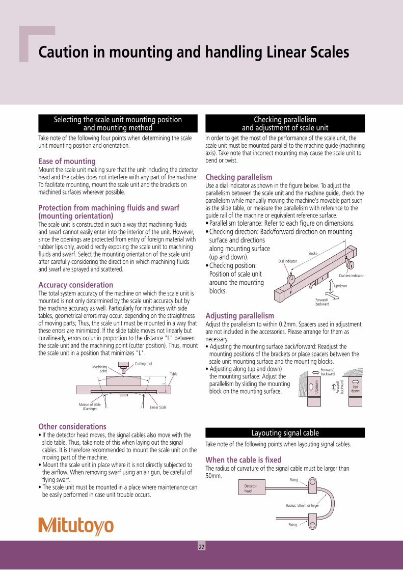
Checking parallelism and adjustment of scale unit
In order to get the most of the performance of the scale unit, the scale unit must be mounted parallel to the machine guide (machining axis). Take note that incorrect mounting may cause the scale unit to bend or twist.
Checking parallelismUse a dial indicator as shown in the figure below. To adjust the parallelism between the scale unit and the machine guide, check the parallelism while manually moving the machine's movable part such as the slide table, or measure the parallelism with reference to the guide rail of the machine or equivalent reference surface.• Parallelism tolerance: Refer to each figure on dimensions.• Checking direction: Back/forward direction on mounting
surface and directions along mounting surface (up and down).
• Checking position: Position of scale unit around the mounting blocks.
Layouting signal cableTake note of the following points when layouting signal cables.
When the cable is fixedThe radius of curvature of the signal cable must be larger than 50mm.
Caution in mounting and handling Linear Scales
Selecting the scale unit mounting position and mounting method
Take note of the following four points when determining the scale unit mounting position and orientation.
Ease of mountingMount the scale unit making sure that the unit including the detector head and the cables does not interfere with any part of the machine. To facilitate mounting, mount the scale unit and the brackets on machined surfaces wherever possible.
Protection from machining fluids and swarf (mounting orientation)The scale unit is constructed in such a way that machining fluids and swarf cannot easily enter into the interior of the unit. However, since the openings are protected from entry of foreign material with rubber lips only, avoid directly exposing the scale unit to machining fluids and swarf. Select the mounting orientation of the scale unit after carefully considering the direction in which machining fluids and swarf are sprayed and scattered.
Accuracy considerationThe total system accuracy of the machine on which the scale unit is mounted is not only determined by the scale unit accuracy but by the machine accuracy as well. Particularly for machines with side tables, geometrical errors may occur, depending on the straightness of moving parts; Thus, the scale unit must be mounted in a way that these errors are minimized. If the slide table moves not linearly but curvilinearly, errors occur in proportion to the distance "L" between the scale unit and the machining point (cutter position). Thus, mount the scale unit in a position that minimizes "L".
Adjusting parallelismAdjust the parallelism to within 0.2mm. Spacers used in adjustment are not included in the accessories. Please arrange for them as necessary.• Adjusting the mounting surface back/forward: Readjust the
mounting positions of the brackets or place spacers between the scale unit mounting surface and the mounting blocks.
• Adjusting along (up and down) the mounting surface: Adjust the parallelism by sliding the mounting block on the mounting surface.
Other considerations• If the detector head moves, the signal cables also move with the
slide table. Thus, take note of this when laying out the signal cables. It is therefore recommended to mount the scale unit on the moving part of the machine.
• Mount the scale unit in place where it is not directly subjected to the airflow. When removing swarf using an air gun, be careful of flying swarf.
• The scale unit must be mounted in a place where maintenance can be easily performed in case unit trouble occurs.
23
Technical Information
Flexible cover
Radius: 100mm or larger
Detectorhead
Scalemain unit
DetectorheadRubber lip
15mm or less
Apply silicone grease to the overall length with a close or paper.
Greasing
1
Linear ScaleAir compressor
Air supply unit: 06ACU217
2 3
4
5. Flow control valve: 06ACU220
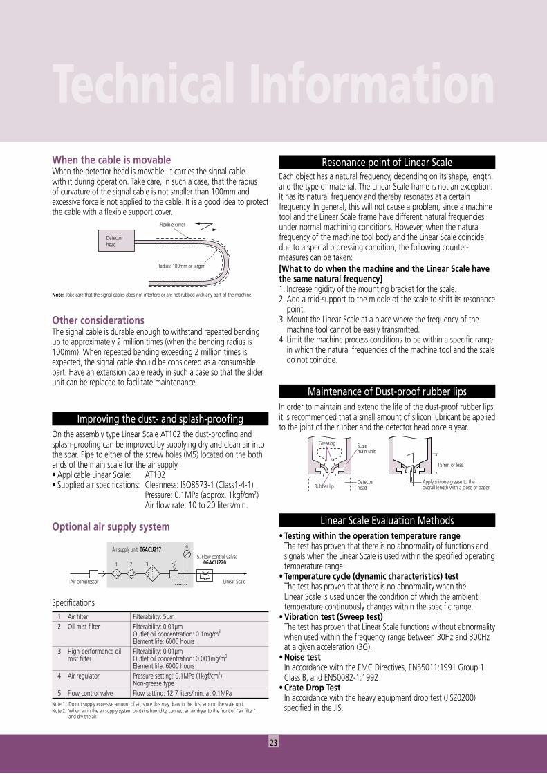
Resonance point of Linear ScaleEach object has a natural frequency, depending on its shape, length, and the type of material. The Linear Scale frame is not an exception. It has its natural frequency and thereby resonates at a certain frequency. In general, this will not cause a problem, since a machine tool and the Linear Scale frame have different natural frequencies under normal machining conditions. However, when the natural frequency of the machine tool body and the Linear Scale coincide due to a special processing condition, the following counter-measures can be taken:[What to do when the machine and the Linear Scale have the same natural frequency]1. Increase rigidity of the mounting bracket for the scale.2. Add a mid-support to the middle of the scale to shift its resonance
point.3. Mount the Linear Scale at a place where the frequency of the
machine tool cannot be easily transmitted.4. Limit the machine process conditions to be within a specific range
in which the natural frequencies of the machine tool and the scale do not coincide.
Specifications1 Air filter Filterability: 5µm 2 Oil mist filter Filterability: 0.01µm
Outlet oil concentration: 0.1mg/m3
Element life: 6000 hours3 High-performance oil
mist filterFilterability: 0.01µmOutlet oil concentration: 0.001mg/m3
Element life: 6000 hours4 Air regulator Pressure setting: 0.1MPa (1kgf/cm2)
Non-grease type5 Flow control valve Flow setting: 12.7 liters/min. at 0.1MPa
Note 1: Do not supply excessive amount of air, since this may draw in the dust around the scale unit.Note 2: When air in the air supply system contains humidity, connect an air dryer to the front of “air filter” and dry the air.
Improving the dust- and splash-proofingOn the assembly type Linear Scale AT102 the dust-proofing and splash-proofing can be improved by supplying dry and clean air into the spar. Pipe to either of the screw holes (M5) located on the both ends of the main scale for the air supply.• Applicable Linear Scale: AT102• Supplied air specifications: Cleanness: ISO8573-1 (Class1-4-1) Pressure: 0.1MPa (approx. 1kgf/cm2)
Air flow rate: 10 to 20 liters/min.
Optional air supply system Linear Scale Evaluation Methods• Testing within the operation temperature range The test has proven that there is no abnormality of functions and
signals when the Linear Scale is used within the specified operating temperature range.
• Temperature cycle (dynamic characteristics) test The test has proven that there is no abnormality when the
Linear Scale is used under the condition of which the ambient temperature continuously changes within the specific range.
• Vibration test (Sweep test) The test has proven that Linear Scale functions without abnormality
when used within the frequency range between 30Hz and 300Hz at a given acceleration (3G).
• Noise test In accordance with the EMC Directives, EN55011:1991 Group 1
Class B, and EN50082-1:1992• Crate Drop Test In accordance with the heavy equipment drop test (JISZ0200)
specified in the JIS.
Maintenance of Dust-proof rubber lipsIn order to maintain and extend the life of the dust-proof rubber lips, it is recommended that a small amount of silicon lubricant be applied to the joint of the rubber and the detector head once a year.
Other considerationsThe signal cable is durable enough to withstand repeated bending up to approximately 2 million times (when the bending radius is 100mm). When repeated bending exceeding 2 million times is expected, the signal cable should be considered as a consumable part. Have an extension cable ready in such a case so that the slider unit can be replaced to facilitate maintenance.
Note: Take care that the signal cables does not interfere or are not rubbed with any part of the machine.
When the cable is movableWhen the detector head is movable, it carries the signal cable with it during operation. Take care, in such a case, that the radius of curvature of the signal cable is not smaller than 100mm and excessive force is not applied to the cable. It is a good idea to protect the cable with a flexible support cover.
24
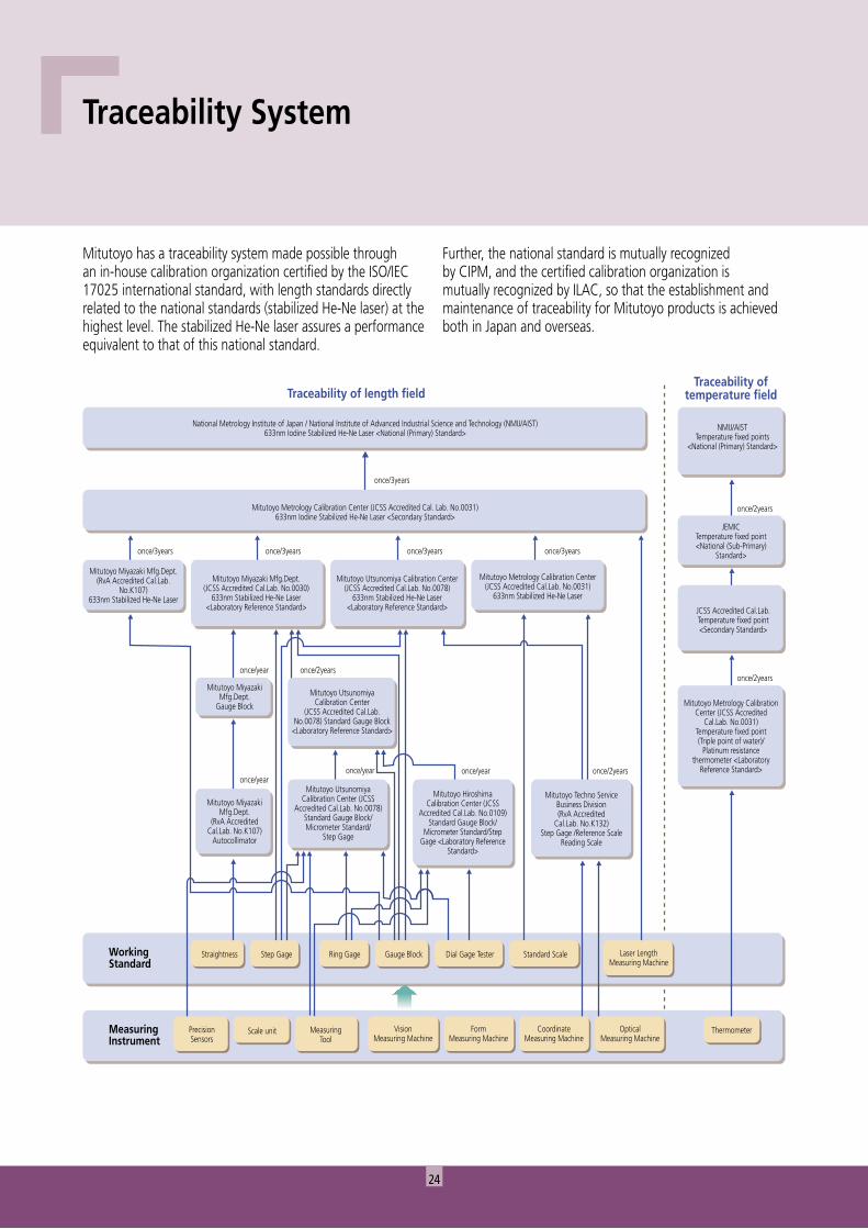
Traceability of length fieldTraceability of
temperature field
National Metrology Institute of Japan / National Institute of Advanced Industrial Science and Technology (NMIJ/AIST)633nm Iodine Stabilized He-Ne Laser <National (Primary) Standard>
Thermometer
Mitutoyo Metrology CalibrationCenter (JCSS Accredited
Cal.Lab. No.0031)Temperature fixed point(Triple point of water)/
Platinum resistancethermometer <Laboratory
Reference Standard>
JCSS Accredited Cal.Lab.Temperature fixed point<Secondary Standard>
JEMICTemperature fixed point<National (Sub-Primary)
Standard>
once/2years
once/2years
NMIJ/AISTTemperature fixed points
<National (Primary) Standard>
once/3years
once/3years once/3years once/3years once/3years
Mitutoyo Metrology Calibration Center (JCSS Accredited Cal. Lab. No.0031)633nm Iodine Stabilized He-Ne Laser <Secondary Standard>
Mitutoyo Miyazaki Mfg.Dept.(RvA Accredited Cal.Lab.
No.K107)633nm Stabilized He-Ne Laser
Mitutoyo Miyazaki Mfg.Dept.(JCSS Accredited Cal.Lab. No.0030)
633nm Stabilized He-Ne Laser<Laboratory Reference Standard>
Mitutoyo MiyazakiMfg.Dept.
Gauge Block
Mitutoyo MiyazakiMfg.Dept.
(RvA AccreditedCal.Lab. No.K107)
Autocollimator
Straightness
once/year once/2years
once/year once/2yearsonce/year
WorkingStandard
MeasuringInstrument
Step Gage Ring Gage Gauge Block Dial Gage Tester Standard Scale Laser LengthMeasuring Machine
PrecisionSensors
Scale unit MeasuringTool
VisionMeasuring Machine
FormMeasuring Machine
CoordinateMeasuring Machine
OpticalMeasuring Machine
Mitutoyo UtsunomiyaCalibration Center
(JCSS Accredited Cal.Lab.No.0078) Standard Gauge Block
<Laboratory Reference Standard>
Mitutoyo UtsunomiyaCalibration Center (JCSS
Accredited Cal.Lab. No.0078)Standard Gauge Block/Micrometer Standard/
Step Gage
Mitutoyo HiroshimaCalibration Center (JCSS
Accredited Cal.Lab. No.0109)Standard Gauge Block/
Micrometer Standard/StepGage <Laboratory Reference
Standard>
Mitutoyo Techno ServiceBusiness Division(RvA Accredited
Cal.Lab. No.K132)Step Gage /Reference Scale
Reading Scale
Mitutoyo Utsunomiya Calibration Center(JCSS Accredited Cal.Lab. No.0078)
633nm Stabilized He-Ne Laser<Laboratory Reference Standard>
Mitutoyo Metrology Calibration Center(JCSS Accredited Cal.Lab. No.0031)
633nm Stabilized He-Ne Laser
once/year
Mitutoyo has a traceability system made possible through an in-house calibration organization certified by the ISO/IEC 17025 international standard, with length standards directly related to the national standards (stabilized He-Ne laser) at the highest level. The stabilized He-Ne laser assures a performance equivalent to that of this national standard.
Traceability System
Further, the national standard is mutually recognized by CIPM, and the certified calibration organization is mutually recognized by ILAC, so that the establishment and maintenance of traceability for Mitutoyo products is achieved both in Japan and overseas.
25
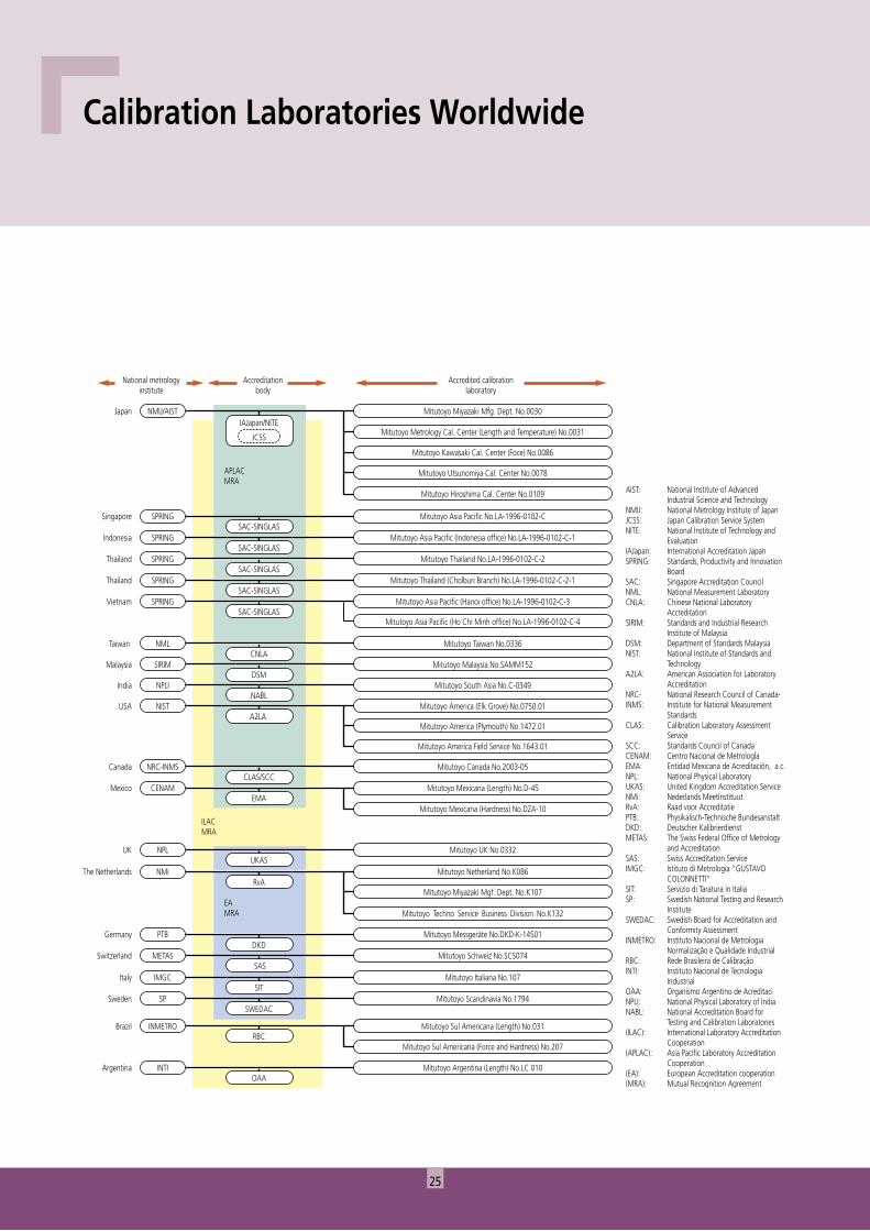
Japan
ILACMRA
APLACMRA
EAMRA
Mitutoyo Miyazaki Mfg. Dept. No.0030NMIJ/AIST
Mitutoyo Metrology Cal. Center (Length and Temperature) No.0031
Mitutoyo Kawasaki Cal. Center (Foce) No.0086
Mitutoyo Utsunomiya Cal. Center No.0078
Mitutoyo Hiroshima Cal. Center No.0109
Singapore Mitutoyo Asia Pacific No.LA-1996-0102-CSPRINGSAC-SINGLAS
Indonesia Mitutoyo Asia Pacific (Indonesia office) No.LA-1996-0102-C-1SAC-SINGLAS
SPRING
Thailand Mitutoyo Thailand No.LA-1996-0102-C-2SAC-SINGLAS
SPRING
Thailand Mitutoyo Thailand (Cholburi Branch) No.LA-1996-0102-C-2-1
Mitutoyo Asia Pacific (Ho Chi Minh office) No.LA-1996-0102-C-4
SAC-SINGLASSPRING
Vietnam Mitutoyo Asia Pacific (Hanoi office) No.LA-1996-0102-C-3SAC-SINGLAS
SPRING
Taiwan Mitutoyo Taiwan No.0336NMLCNLA
Malaysia Mitutoyo Malaysia No.SAMM152SIRIMDSM
India Mitutoyo South Asia No.C-0349NPLINABL
USA Mitutoyo America (Elk Grove) No.0750.01NISTA2LA
Mitutoyo America (Plymouth) No.1472.01
Mitutoyo America Field Service No.1643.01
UK Mitutoyo UK No.0332NPLUKAS
Canada Mitutoyo Canada No.2003-05NRC-INMSCLAS/SCC
The Netherlands Mitutoyo Netherland No.K086NMiRvA
Mitutoyo Miyazaki Mgf. Dept. No.K107
Mitutoyo Techno Service Business Division No.K132
Germany Mitutoyo Messgeräte No.DKD-K-14501PTBDKD
Switzerland Mitutoyo Schweiz No.SCS074METAS SAS
Italy Mitutoyo Italiana No.107IMGCSIT
Sweden Mitutoyo Scandinavia No.1794SPSWEDAC
Brazil Mitutoyo Sul Americana (Length) No.031INMETRORBC
Mitutoyo Sul Americana (Force and Hardness) No.207
Mexico Mitutoyo Mexicana (Length) No.D-45CENAMEMA
Mitutoyo Mexicana (Hardness) No.DZA-10
Argentina Mitutoyo Argentina (Length) No.LC 010INTIOAA
IAJapan/NITE
JCSS
Accredited calibrationlaboratory
Accreditationbody
National metrologyinstitute
AIST: National Institute of Advanced Industrial Science and TechnologyNMIJ: National Metrology Institute of JapanJCSS: Japan Calibration Service SystemNITE: National Institute of Technology and EvaluationIAJapan: International Accreditation JapanSPRING: Standards, Productivity and Innovation BoardSAC: Singapore Accreditation CouncilNML: National Measurement LaboratoryCNLA: Chinese National Laboratory AccreditationSIRIM: Standards and Industrial Research Institute of MalaysiaDSM: Department of Standards MalaysiaNIST: National Institute of Standards and TechnologyA2LA: American Association for Laboratory AccreditationNRC- National Research Council of Canada-INMS: Institute for National Measurement StandardsCLAS: Calibration Laboratory Assessment ServiceSCC: Standards Council of CanadaCENAM: Centro Nacional de MetrologÌaEMA: Entidad Mexicana de Acreditación, a.c.NPL: National Physical LaboratoryUKAS: United Kingdom Accreditation ServiceNMi: Nederlands Meetinstituut RvA: Raad voor AccreditatiePTB: Physikalisch-Technische BundesanstaltDKD: Deutscher KalibrierdienstMETAS: The Swiss Federal Office of Metrology and AccreditationSAS: Swiss Accreditation ServiceIMGC: Istituto di Metrologia "GUSTAVO COLONNETTI"SIT: Servizio di Taratura in ItaliaSP: Swedish National Testing and Research InstituteSWEDAC: Swedish Board for Accreditation and Conformity AssessmentINMETRO: Instituto Nacional de Metrologia Normalização e Qualidade IndustrialRBC: Rede Brasileira de CalibraçãoINTI: Instituto Nacional de Tecnologia IndustrialOAA: Organismo Argentino de AcreditaciNPLI: National Physical Laboratory of IndiaNABL: National Accreditation Board for Testing and Calibration Laboratories(ILAC): International Laboratory Accreditation Cooperation(APLAC): Asia Pacific Laboratory Accreditation Cooperation(EA): European Accreditation cooperation(MRA): Mutual Recognition Agreement
Calibration Laboratories Worldwide
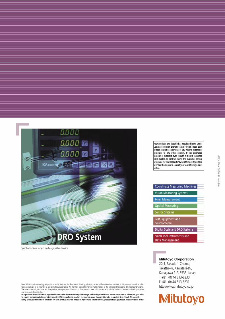
Small Tool Instruments andData Management
Digital Scale and DRO Systems
Test Equipment and Seismometers
Sensor Systems
Optical Measuring
Form Measurement
Coordinate Measuring Machines
Vision Measuring Systems
Mitutoyo Corporation20-1, Sakado 1-Chome,Takatsu-ku, Kawasaki-shi,Kanagawa 213-8533, JapanT +81 (0) 44 813-8230F +81 (0) 44 813-8231http://www.mitutoyo.co.jp
Note: All information regarding our products, and in particular the illustrations, drawings, dimensional and performance data contained in this pamphlet, as well as other technical data are to be regarded as approximate average values. We therefore reserve the right to make changes to the corresponding designs, dimensions and weights. The stated standards, similar technical regulations, descriptions and illustrations of the products were valid at the time of printing. Only quotations submitted by ourselves may be regarded as definitive.Our products are classified as regulated items under Japanese Foreign Exchange and Foreign Trade Law. Please consult us in advance if you wish to export our products to any other country. If the purchased product is exported, even though it is not a regulated item (Catch-All controls item), the customer service available for that product may be affected. If you have any questions, please consult your local Mitutoyo sales office.
Our products are classified as regulated items under Japanese Foreign Exchange and Foreign Trade Law. Please consult us in advance if you wish to export our products to any other country. If the purchased product is exported, even though it is not a regulated item (Catch-All controls item), the customer service available for that product may be affected. If you have any questions, please consult your local Mitutoyo sales office.
109.
5 07
08 2
B (N
E) N
E, P
rinte
d in
Japa
n
Specifications are subject to change without notice.
DRO System
Recommended