Operator ManualFor printer model:
Copyrights
Any unauthorized reproduction of the contents of this document, in part or whole, is strictly prohibited.
Limitation of Liability
SATO Corporation and its subsidiaries in Japan, the U.S. and other countries make no representations or warranties of any kind regarding this material, including, but not limited to, implied warranties of merchantability and fitness for a particular purpose. SATO Corporation shall not be held responsible for errors contained herein or any omissions from this material or for any damages, whether direct, indirect, incidental or consequential, in connection with the furnishing, distribution, performance or use of this material.
Specifications and contents in this document are subject to change without notice.
Be sure to perform a virus check for the USB memory or SD card before connecting it to the printer. SATO Corporation shall not be held responsible for a malfunction of the printer caused by a virus infection through the USB memory or SD card.
Trademarks
SATO is a registered trademark of SATO Holdings Corporation and its subsidiaries in Japan, the U.S. and other countries.
Secure Digital (SD) Card is a registered trademark of the SD Card Association.
QR Code is a registered trademark of DENSO WAVE INCORPORATED.
Bluetooth is a trademark of Bluetooth SIG, Inc., U.S.A.
WPA™ and WPA2™ are registered trademarks of Wi-Fi Alliance.
SAP® is a registered trademark of SAP AG.
Oracle is a registered trademark of Oracle Corporation and/or its affiliates.
All other trademarks are the property of their respective owners.
Version: GBS-S84ex_S86ex-r06-20-03-17OM
© 2017 SATO Corporation. All rights reserved.
Table of Contents ................................................................................... 1
Before You Start ..................................................................................... 7
1 Parts Identification............................................................................. 15
1.1 Printer Orientation ............................................................................................ 15
1.2 Parts Identification of the Printer .................................................................... 161.2.1 Front View ............................................................................................................... 161.2.2 Rear View ................................................................................................................ 171.2.3 Internal View............................................................................................................ 18
1.3 Parts on the Operator Panel............................................................................. 191.3.1 Operator Panel ........................................................................................................ 191.3.2 LED Indicator........................................................................................................... 20
2 Installing the Printer .......................................................................... 21
2.1 Installation Precautions.................................................................................... 21
2.2 Installation Space.............................................................................................. 222.2.1 Front View (S84-ex/S86-ex printer) ......................................................................... 222.2.2 Rear View (S84-ex/S86-ex printer).......................................................................... 232.2.3 Media Dispensed View (S84-ex printer) .................................................................. 232.2.4 Top View (S84-ex printer)........................................................................................ 242.2.5 Media Dispensed View (S86-ex printer) .................................................................. 252.2.6 Top View (S86-ex printer)........................................................................................ 26
2.3 Installing the Printer onto a Support Structure/Applicator ........................... 27
2.4 Checking the Bundled Accessories ................................................................ 28
2.5 Connecting the Interface Cable ....................................................................... 292.5.1 Available Interfaces ................................................................................................. 292.5.2 Interface Connections.............................................................................................. 292.5.3 Interface Settings..................................................................................................... 302.5.4 Interface Combination ............................................................................................. 31
2.6 Connecting the Power Cord............................................................................. 32
2.7 Power On/Off the Printer .................................................................................. 332.7.1 Power On the Printer ............................................................................................... 332.7.2 Power Off the Printer ............................................................................................... 33
2.8 Installing Optional Memory Storage................................................................ 342.8.1 Installing the Optional SD Card ............................................................................... 342.8.2 Removing the Optional SD Card ............................................................................. 352.8.3 Installing the Optional USB Memory........................................................................ 35
Table of Contents
1S84-ex/S86-ex Operator Manual
Table of Contents
2
3 Loading the Ribbon and Media........................................................... 37
3.1 Checking the Ink Side of the Ribbon............................................................... 37
3.2 Loading the Ribbon .......................................................................................... 38
3.3 Removing the Ribbon ....................................................................................... 41
3.4 Usable Media ..................................................................................................... 423.4.1 Adjusting the Position of the Media Sensor............................................................. 42
3.5 Loading Media ................................................................................................... 433.5.1 Loading Label with Dispenser ................................................................................. 433.5.2 Loading Media without Using Dispenser ................................................................. 46
4 Operation and Configuration.............................................................. 47
4.1 Display and Operation ...................................................................................... 474.1.1 Normal Mode Display and Icons.............................................................................. 474.1.2 Setting Mode Menu and Icons................................................................................. 514.1.3 Error Display and Icons ........................................................................................... 524.1.4 Setting Display......................................................................................................... 53
4.2 Operating Modes............................................................................................... 554.2.1 Online Mode/Pause Mode/Offline Mode.................................................................. 584.2.2 Adjusting the Display Brightness ............................................................................. 594.2.3 Adjusting the Buzzer Volume .................................................................................. 594.2.4 Canceling the Print Job ........................................................................................... 604.2.5 Adjustment Mode..................................................................................................... 614.2.6 Work Shift Setting Mode.......................................................................................... 634.2.7 Simple Standalone Mode ........................................................................................ 654.2.8 Setting Mode Menu ................................................................................................. 694.2.9 User Mode ............................................................................................................... 714.2.10 Interface Mode....................................................................................................... 764.2.11 Memory Mode...................................................................................................... 1134.2.12 Service Mode....................................................................................................... 1214.2.13 Advanced Mode................................................................................................... 1464.2.14 Hex Dump Mode.................................................................................................. 1664.2.15 RFID User Mode.................................................................................................. 1714.2.16 Information Mode................................................................................................. 1784.2.17 Test Print Mode ................................................................................................... 1834.2.18 Default Setting Mode ........................................................................................... 1864.2.19 Download Mode................................................................................................... 1894.2.20 Upload Mode ....................................................................................................... 1944.2.21 Hidden Setting Mode ........................................................................................... 1964.2.22 Wireless LAN Certificate Download Mode........................................................... 1974.2.23 Site Survey Mode ................................................................................................ 199
S84-ex/S86-ex Operator Manual
Table of Contents
4.3 Web Configuration .......................................................................................... 2034.3.1 Information............................................................................................................. 2034.3.2 External Signal Status ........................................................................................... 2044.3.3 Sensor Level.......................................................................................................... 2054.3.4 Adjustment Mode................................................................................................... 2064.3.5 User Mode ............................................................................................................. 2074.3.6 Interface Mode....................................................................................................... 2084.3.7 Interface Mode (SNMP)......................................................................................... 2094.3.8 WLAN Setting ........................................................................................................ 2114.3.9 WLAN Certificate ................................................................................................... 2134.3.10 Memory Mode...................................................................................................... 2144.3.11 Service Mode....................................................................................................... 2154.3.12 Advanced Mode................................................................................................... 2174.3.13 RFID Mode .......................................................................................................... 2204.3.14 Emulation Mode................................................................................................... 2214.3.15 Printer Configuration (Read)................................................................................ 2234.3.16 Printer Configuration (Write) ................................................................................ 2244.3.17 System/Others..................................................................................................... 2254.3.18 Test Print ............................................................................................................. 2264.3.19 Restart Printer ..................................................................................................... 227
5 Emulation Mode................................................................................ 229
5.1 Emulation Module Loader .............................................................................. 2295.1.1 Loading the Emulation Module .............................................................................. 2305.1.2 Deleting the Emulation Module.............................................................................. 2325.1.3 Downloading the Emulation Module ...................................................................... 2345.1.4 Emulation Module Error......................................................................................... 237
5.2 SZPL Emulation Mode .................................................................................... 2385.2.1 Auto Emulation Mode Switching Function ............................................................. 242
5.3 SDPL Emulation Mode.................................................................................... 243
5.4 SIPL Emulation Mode ..................................................................................... 251
6 Cleaning and Performing Printer Adjustments ................................ 253
6.1 Maintenance .................................................................................................... 253
6.2 Maintenance of the Print Head and Platen Roller ........................................ 2546.2.1 Maintenance using the Cleaning Kit ...................................................................... 2546.2.2 Maintenance using the Cleaning Sheet................................................................. 257
6.3 Adjusting the Base Reference Point ............................................................. 2596.3.1 About the Base Reference Point ........................................................................... 2596.3.2 Adjusting the Print Position.................................................................................... 2606.3.3 Adjusting the Media Stop Position......................................................................... 2616.3.4 More about the Media Stop Position ..................................................................... 2626.3.5 Limitation on Base Reference Point Adjustment ................................................... 263
3S84-ex/S86-ex Operator Manual
Table of Contents
4
6.4 Adjusting the Print Quality............................................................................. 2646.4.1 Adjustment of the Print Darkness .......................................................................... 2646.4.2 Adjusting the Print Speed ...................................................................................... 265
6.5 Adjusting the Media Sensors......................................................................... 2676.5.1 Adjusting the Media Sensor Automatically ............................................................ 2676.5.2 Adjusting the I-mark Sensor Level Manually ......................................................... 2706.5.3 Adjusting the Gap Sensor Level Manually............................................................. 2736.5.4 Adjusting the Paper End Sensor ........................................................................... 275
6.6 Adjusting the Head Pressure Balance .......................................................... 277
6.7 Adjusting the Head Position .......................................................................... 2796.7.1 Left - Right Pressure Balance Setting ................................................................... 2796.7.2 Front - Rear Head Alignment................................................................................. 280
6.8 Adjusting the Ribbon Tension Balance ........................................................ 281
6.9 Adjusting the Media Feed Roller Balance..................................................... 282
7 Troubleshooting................................................................................ 283
7.1 When an Error Message Occurs.................................................................... 2837.1.1 More Information about Command Error ............................................................... 2917.1.2 More Information about Head Check Function...................................................... 292
7.2 When a Warning Message Occurs ................................................................ 293
7.3 When the LED Lights Red/Blue ..................................................................... 295
7.4 Troubleshooting Table ................................................................................... 2967.4.1 No Power/Nothing on the Screen .......................................................................... 2967.4.2 Cannot Feed the Media ......................................................................................... 2967.4.3 Can Feed the Media but Cannot Print ................................................................... 2977.4.4 Bad Print Quality.................................................................................................... 2987.4.5 Incorrect Print Position .......................................................................................... 299
7.5 Interface Troubleshooting.............................................................................. 3007.5.1 USB Interface ........................................................................................................ 3007.5.2 LAN Ethernet Interface .......................................................................................... 3007.5.3 Bluetooth Interface (Optional)................................................................................ 3007.5.4 RS-232C Interface................................................................................................. 3017.5.5 IEEE1284 Interface ............................................................................................... 3017.5.6 External Signal Interface (EXT) ............................................................................. 3017.5.7 Wireless LAN Interface (Optional) ......................................................................... 302
S84-ex/S86-ex Operator Manual
Table of Contents
8 Appendix ........................................................................................... 303
8.1 List of Initial Values ........................................................................................ 3038.1.1 Normal Mode ......................................................................................................... 3038.1.2 User Mode ............................................................................................................. 3038.1.3 Interface Mode....................................................................................................... 3048.1.4 Memory Mode........................................................................................................ 3078.1.5 Advanced Mode..................................................................................................... 3078.1.6 Hex Dump Mode.................................................................................................... 3108.1.7 RFID User Mode.................................................................................................... 3108.1.8 Test Print Mode ..................................................................................................... 3118.1.9 Default Setting Mode ............................................................................................. 3118.1.10 Service Mode....................................................................................................... 3128.1.11 Hidden Setting Mode ........................................................................................... 3138.1.12 Work Shift Setting Mode...................................................................................... 3138.1.13 Simple Standalone Mode .................................................................................... 3148.1.14 Wireless LAN Setting........................................................................................... 314
8.2 Media Sensor Positions and Media Stop Positions..................................... 318
8.3 About Legacy Command Support ................................................................. 3208.3.1 Legacy Command Support .................................................................................... 3208.3.2 Compatible Mode - Print Head Width (only for S86-ex printer) ............................. 3218.3.3 Print Head Width and Printable Area Range ......................................................... 323
8.4 LCD Power Saving Mode................................................................................ 325
8.5 Input/Output Signal of the External Signal ................................................... 326
8.6 Notification Function ...................................................................................... 328
8.7 Replacing Consumable Parts ........................................................................ 3308.7.1 Replacing the Print Head....................................................................................... 3308.7.2 Replacing the Platen Roller ................................................................................... 3328.7.3 Replacing the Pressure Roller ............................................................................... 3348.7.4 Replacing the Media Feed Roller .......................................................................... 3368.7.5 Replacing the Fan Filter ........................................................................................ 337
8.8 Media Motion of the Printer Operation.......................................................... 3388.8.1 Feed Motion........................................................................................................... 3388.8.2 Paper End.............................................................................................................. 3388.8.3 Sensor Error .......................................................................................................... 3418.8.4 Ribbon Error .......................................................................................................... 342
8.9 Print Speed and Media Size ........................................................................... 343
8.10 Optional Ribbon Saver ................................................................................. 3448.10.1 Ribbon Saver Operation ...................................................................................... 3448.10.2 Ribbon Saver Timing Charts ............................................................................... 3458.10.3 Ribbon Saver Operation and Ribbon Consumption ............................................ 3468.10.4 Ribbon Specification for the Ribbon Saver.......................................................... 3498.10.5 Label Specification for the Ribbon Saver ............................................................ 349
5S84-ex/S86-ex Operator Manual
Table of Contents
6
8.11 Optional UHF RFID Configuration ............................................................... 3508.11.1 Printing RFID Tag Errors ..................................................................................... 3528.11.2 RFID Error and Reset Timing .............................................................................. 3558.11.3 External (EXT) Signal Interfaces when RFID Module is Enabled........................ 3588.11.4 RFID Printing Tips ............................................................................................... 359
8.12 Printer Specifications ................................................................................... 3608.12.1 Hardware ............................................................................................................. 3608.12.2 Ribbon and Media ............................................................................................... 3628.12.3 Interface............................................................................................................... 3638.12.4 Built-in Functions ................................................................................................. 3648.12.5 Printer Languages ............................................................................................... 3648.12.6 Fonts/Symbols/Barcodes..................................................................................... 3658.12.7 Options ................................................................................................................ 3678.12.8 Accessories ......................................................................................................... 3678.12.9 Standards ............................................................................................................ 367
8.13 Interface Specifications................................................................................ 3688.13.1 USB Interface ...................................................................................................... 3698.13.2 LAN Ethernet Interface ........................................................................................ 3708.13.3 RS-232C Interface............................................................................................... 3728.13.4 IEEE1284 Interface ............................................................................................. 3748.13.5 External Signal Interface (EXT) ........................................................................... 3768.13.6 Bluetooth Interface .............................................................................................. 3888.13.7 Wireless LAN Interface........................................................................................ 389
S84-ex/S86-ex Operator Manual

Thank you for purchasing this SATO S84-ex/S86-ex print engine (hereafter referred to as “the printer”).This manual supplies basic information on how to operate the printer. Read the manual carefully to understand each function before operation.
Features of the ProductThis SATO S84-ex/S86-ex print engine is a high-performance, automated print/apply labeling system with a user-friendly design and equipped with versatile functions. This print engine has a durable design for non-stop operation.
The main features of the printer are as follows:
• Equipped with a two-color backlight LCD and a two-color status LED for improved monitoring of the printer status.
• Durable design for harsh environment.
• High-speed throughput printing with maximum 16 ips print speed and adjustable backfeed speed control.
• Print head can be replaced easily without using extra tools.
• New designed sensor cover with nonstick surface that can be easily removed and cleaned without any tools.
• Easily upload/download data to/from an SD card or USB memory, or by using the SATO All In One Tool application.
• Supports remote printer setting through the SATO All In One Tool application or a web browser.
• Supports a multi-language display menu and printing of Asian fonts.
• Supports emulations in standard firmware.
• Supports various communication interfaces.
• Supports SNTP protocol.
Before You Start
7S84-ex/S86-ex Operator Manual
Before You Start
8
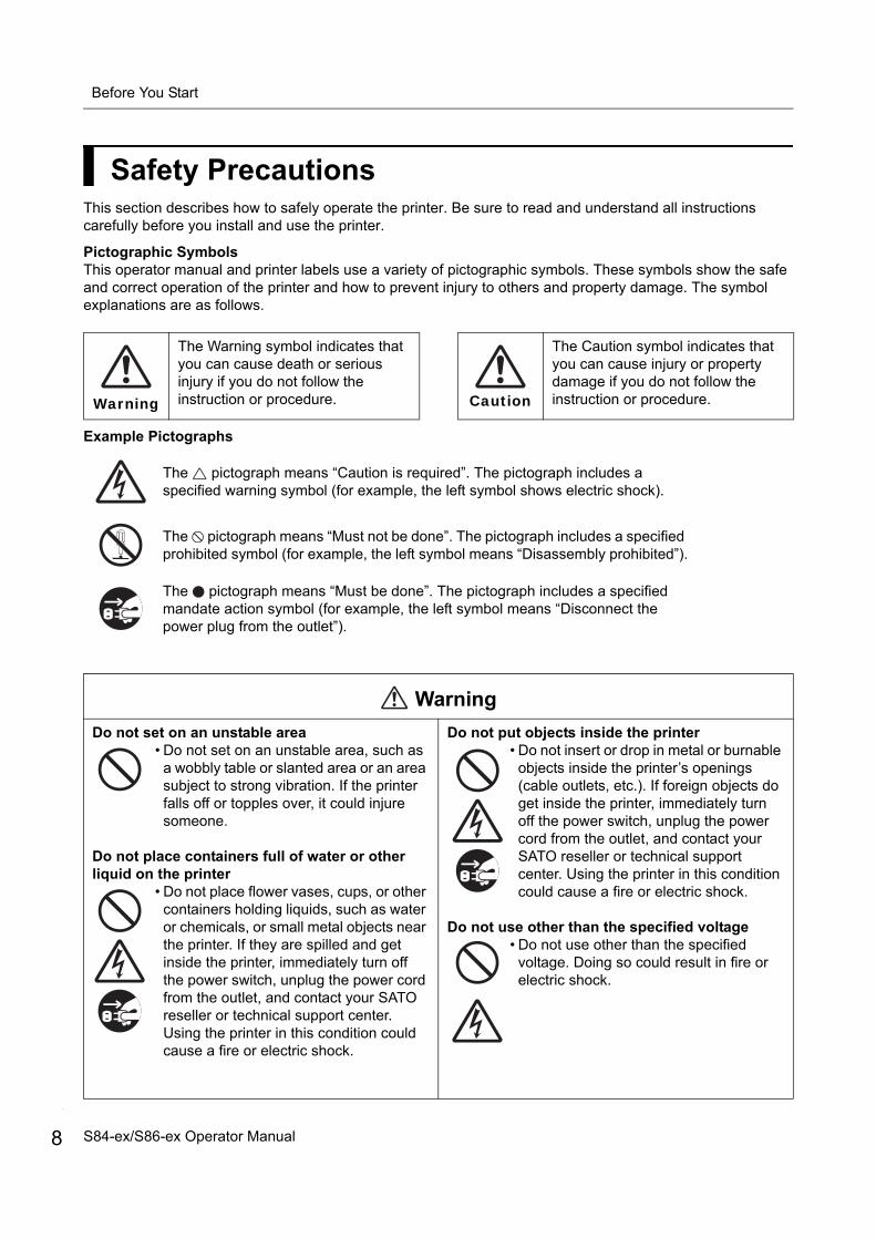
Safety PrecautionsThis section describes how to safely operate the printer. Be sure to read and understand all instructions carefully before you install and use the printer.
Pictographic SymbolsThis operator manual and printer labels use a variety of pictographic symbols. These symbols show the safe and correct operation of the printer and how to prevent injury to others and property damage. The symbol explanations are as follows.
Example Pictographs
Warning
The Warning symbol indicates that you can cause death or serious injury if you do not follow the instruction or procedure. Caution
The Caution symbol indicates that you can cause injury or property damage if you do not follow the instruction or procedure.
The pictograph means “Caution is required”. The pictograph includes a specified warning symbol (for example, the left symbol shows electric shock).
The pictograph means “Must not be done”. The pictograph includes a specified prohibited symbol (for example, the left symbol means “Disassembly prohibited”).
The pictograph means “Must be done”. The pictograph includes a specified mandate action symbol (for example, the left symbol means “Disconnect the power plug from the outlet”).
Warning
Do not set on an unstable area• Do not set on an unstable area, such as
a wobbly table or slanted area or an area subject to strong vibration. If the printer falls off or topples over, it could injure someone.
Do not place containers full of water or other liquid on the printer
• Do not place flower vases, cups, or other containers holding liquids, such as water or chemicals, or small metal objects near the printer. If they are spilled and get inside the printer, immediately turn off the power switch, unplug the power cord from the outlet, and contact your SATO reseller or technical support center. Using the printer in this condition could cause a fire or electric shock.
Do not put objects inside the printer• Do not insert or drop in metal or burnable
objects inside the printer’s openings (cable outlets, etc.). If foreign objects do get inside the printer, immediately turn off the power switch, unplug the power cord from the outlet, and contact your SATO reseller or technical support center. Using the printer in this condition could cause a fire or electric shock.
Do not use other than the specified voltage• Do not use other than the specified
voltage. Doing so could result in fire or electric shock.
S84-ex/S86-ex Operator Manual

Before You Start
Warning
Always ground the connections• Always connect the printer’s ground wire
to a ground. Not grounding the ground wire could result in electric shock.
Handling the power cord• Do not damage, break, or modify the
power cord. Also, do not place heavy objects on the power cord, heat it, or pull it because doing so could damage the power cord and cause a fire or electric shock.
• If the power cord becomes damaged (core is exposed, wires broken, etc.), contact your SATO reseller or technical support center. Using the power cord in this condition could cause a fire or electric shock.
• Do not modify, excessively bend, twist, or pull the power cord. Using the power cord in such a condition could cause a fire or electric shock.
When the printer has been dropped or broken• If the printer is dropped or broken,
immediately turn off the power switch, unplug the power cord from the outlet, and contact your SATO reseller or technical support center. Using the printer in this condition could cause a fire or electric shock.
Do not use the printer when something is abnormal about it.
• Continuing to use the printer in the event something is abnormal about it, such as smoke or unusual smells coming from it, could result in fire or electric shock. Immediately turn off the power switch, unplug the power cord from the outlet, and contact your SATO reseller or technical support center for repairs. It is dangerous for the customer to try to repair it, so absolutely do not attempt repairs on your own.
Do not disassemble the printer• Do not disassemble or modify the printer.
Doing so could result in fire or electric shock. Ask your SATO reseller or technical support center to conduct internal inspections, adjustments, and repairs.
Do not operate with wet hands• Do not operate the power switch or
unplug the AC adapter with wet hands. Doing so increases the risk of electric shock.
Using the head cleaning fluid• Use of flame or heat around the head
cleaning fluid is prohibited. Absolutely do not heat it or subject it to flames.
• Keep the fluid out of reach of children to prevent them from accidentally drinking it. If a child accidentally drinks the fluid, immediately consult with a physician.
Print head• The print head is hot after printing. Be
careful not to get burned when replacing media or cleaning immediately after printing.
• Touching the edge of the print head with bare hands could result in injury. Be careful not to become injured when replacing media or cleaning.
• The customer should not replace the print head. Doing so could result in injury, burns or electric shock.
Do not use in hazardous locations• The printer is not explosion proof
certified.• Do not use in a potentially explosive
environment or atmosphere.
9S84-ex/S86-ex Operator Manual
Before You Start
10
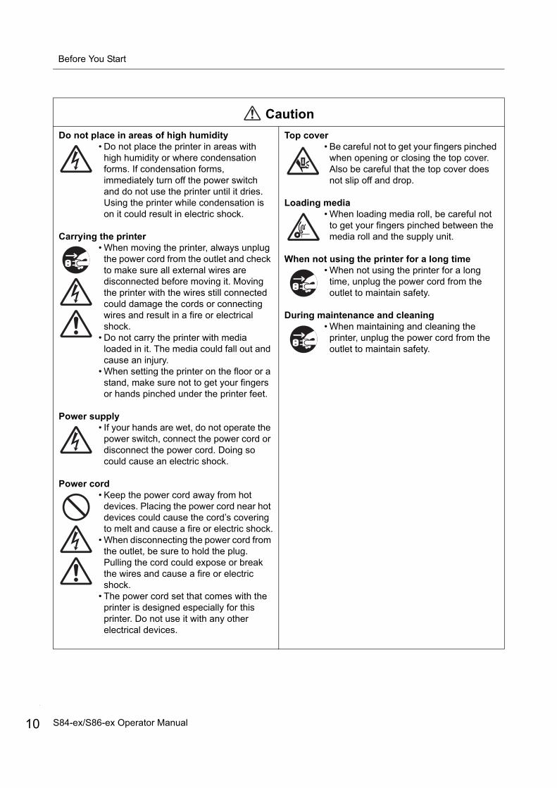
Caution
Do not place in areas of high humidity• Do not place the printer in areas with
high humidity or where condensation forms. If condensation forms, immediately turn off the power switch and do not use the printer until it dries. Using the printer while condensation is on it could result in electric shock.
Carrying the printer• When moving the printer, always unplug
the power cord from the outlet and check to make sure all external wires are disconnected before moving it. Moving the printer with the wires still connected could damage the cords or connecting wires and result in a fire or electrical shock.
• Do not carry the printer with media loaded in it. The media could fall out and cause an injury.
• When setting the printer on the floor or a stand, make sure not to get your fingers or hands pinched under the printer feet.
Power supply• If your hands are wet, do not operate the
power switch, connect the power cord or disconnect the power cord. Doing so could cause an electric shock.
Power cord• Keep the power cord away from hot
devices. Placing the power cord near hot devices could cause the cord’s covering to melt and cause a fire or electric shock.
• When disconnecting the power cord from the outlet, be sure to hold the plug. Pulling the cord could expose or break the wires and cause a fire or electric shock.
• The power cord set that comes with the printer is designed especially for this printer. Do not use it with any other electrical devices.
Top cover• Be careful not to get your fingers pinched
when opening or closing the top cover. Also be careful that the top cover does not slip off and drop.
Loading media• When loading media roll, be careful not
to get your fingers pinched between the media roll and the supply unit.
When not using the printer for a long time• When not using the printer for a long
time, unplug the power cord from the outlet to maintain safety.
During maintenance and cleaning• When maintaining and cleaning the
printer, unplug the power cord from the outlet to maintain safety.
S84-ex/S86-ex Operator Manual

Before You Start
Precautions for Installation and HandlingPrinter operation can be affected by the printer environment.Refer to the following instructions for installation and handling of the S84-ex/S86-ex printer.
Select a Safe Location
Power Supply
Place the printer on a surface that is flat and level.
If the surface is not flat and level, this may cause bad print quality. This may also cause a malfunction and decrease the life span of the printer.
Do not place the printer on a location thatproduces vibration.
Giving serious vibration or shock to the printer may cause a malfunction and shorten the life span of the printer.
Keep the printer out of high temperature andhumidity.
Avoid locations subject to extreme or fast changes in temperature or humidity.
Do not place the printer in a location subject to
water or oil.
Do not place the printer in a location where it will be exposed to water or oil. Water or oil entering inside the printer may cause a fire, electric shock or malfunction.
Avoid dust.
Dust build up may result in bad print quality.
Keep out of direct sunlight.
This printer has a built-in optical sensor. Exposure to direct sunlight will make the sensor less responsive and may cause the media to be sensed incorrectly. Close the top cover when printing.
This printer requires an AC power supply.
Be sure to connect the printer to an AC power supply.
Connect the power cord to a grounded poweroutlet.
Make sure that the printer is connected to a grounded power outlet.
Supply a stable source of electricity to the printer.
When using the printer, do not share its power outlet with other electrical devices that could cause power fluctuations and performance issues with your printer.
11S84-ex/S86-ex Operator Manual
Before You Start
12
Regulatory ApprovalFCC Warning
This equipment has been tested and found to comply with the limits for a Class A digital device, pursuant to Part 15 of the FCC Rules. These limits are designed to provide reasonable protection against harmful interference when the equipment is operated in a commercial environment. This equipment generates, uses, and can radiate radio frequency energy, and if not installed and used in accordance with the instructions, may cause harmful interference to radio communications. Operation of this equipment in a residential area is likely to cause harmful interference in which case the user will be required to correct the interference at his own expense.
FCC Statement for Optional Wireless LAN
This device complies with RF radiation exposure limits set forth for an uncontrolled environment.
The antenna used for this transmitter must be installed to provide a separation distance of at least 20 cm from all people and must not be collocated or operating in conjunction with any other antenna or transmitter.
Bluetooth/Wireless Communication
Compliance StatementThis product has been certified for compliance with the relevant radio interference regulations of your country or region. To make sure continued compliance, do not:
• Disassemble or modify this product.• Remove the certificate label (serial number seal) affixed to this product.
Use of this product near microwave and/or other wireless LAN equipment, or where static electricity or radio interference is present, may shorten the communication distance, or even disable communication.
S84-ex/S86-ex Operator Manual

Before You Start
Industry Canada (IC) Statement for Bluetooth
This device complies with Industry Canada license-exempt RSS standard(s).
Operation is subject to the following two conditions:• This device may not cause interference.• This device must accept any interference, including interference that may cause undesired operation
of the device.
This equipment complies with IC radiation exposure limits set forth for an uncontrolled environment and meets RSS-102 of the IC radio frequency (RF) Exposure rules. This equipment should be installed and operated keeping the radiator at least 20 cm or more away from person’s body (excluding extremities: hands, wrists, feet and ankles).
Le présent appareil est conforme aux CNR d’Industrie Canada applicables aux appareils radio exempts de licence. L’exploitation est autorisée aux deux conditions suivantes :• L’appareil ne doit pas produire de brouillage.• L’utilisateur de l’appareil doit accepter tout brouillage radioélectrique subi, même si le brouillage est
susceptible d’en compromettre le fonctionnement.
Cet équipement est conforme aux limites d’exposition aux rayonnements énoncées pour un environnement non contrôlé et respecte les règles d’exposition aux fréquences radioélectriques (RF) CNR-102 de l’IC. Cet équipement doit être installé et utilisé en gardant une distance de 20 cm ou plus entre le dispositif rayonnant et le corps (à l’exception des extrémités : mains, poignets, pieds et chevilles).
Disposal of Old Electrical & Electronic Equipment (Applicable in the European Union and other European countries with separate collection systems)
A product marked with this symbol on itself or on its packaging shall not be treated as household waste. Instead it shall be handed over to an appropriate collection point for the recycling of electrical and electronic equipment in accordance with local regulations. Inappropriate waste handling of this product may cause detrimental consequences for the environment and damage to human health. The recycling of materials will help to conserve natural resources and contribute to your community. For more detailed information on recycling of this product, contact your local municipal organization, your household waste disposal service or the dealer where you purchased the product.
EN55022 Warning
This is a class A product.
In a domestic environment, this product may cause radio interference, in which case the user may be required to take adequate measures.
EN55022 Warnung
Warnung! Dies ist eine Einrichtung der Klasse A.
Diese Einrichtung kann im Wohnbereich Funkstörungen verursachen. In diesem Fall kann vom Betreiber verlangt werden, angemessene Maßnahmen durchzuführen.
Das Gerät ist nicht für die Benutzung im unmittelbaren Gesichtsfeld am Bildschirmarbeitsplatz vorgesehen. Um störende Reflexionen am Bildschirmarbeitsplatz zu vermeiden, darf dieses Produkt nicht im unmittelbaren Gesichtsfeld platziert werden.
13S84-ex/S86-ex Operator Manual
Before You Start
14
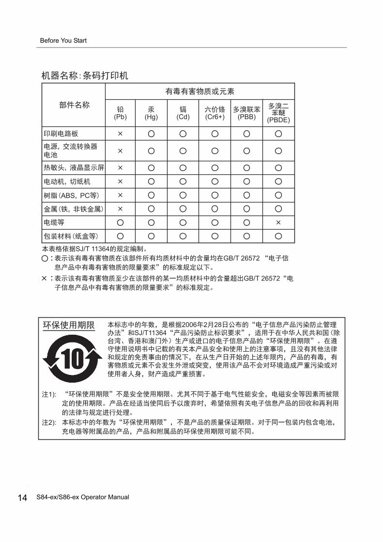
GB/T 26572
(Pb) (Hg) (Cd) (Cr6+) (PBB) (PBDE)
ABS PC
GB/T 26572 SJ/T 11364
2006 2 28SJ/T11364
1):
2):
S84-ex/S86-ex Operator Manual

1.1 Printer OrientationThis printer has two types of orientation as below. The media feed direction varies depending on the type of orientation.
NoteThe pictures in this manual show the S84-ex (Americas: Standard/Right Hand, Europe: Left Hand) printer, unless otherwise stated.When using the right hand (Americas: Opposite/Left Hand, Europe: Right Hand) model, the picture on the right shows a symmetrical opposite view of your printer.When using the S86-ex printer, the dimension of the media compartment is larger.
1 Parts Identification
Media feed direction Media feed direction
Americas: Standard/Right HandEurope/Asia: Left Hand
Americas: Opposite/Left HandEurope/Asia: Right Hand
15S84-ex/S86-ex Operator Manual
1 Parts Identification
16
1.2 Parts Identification of the Printer
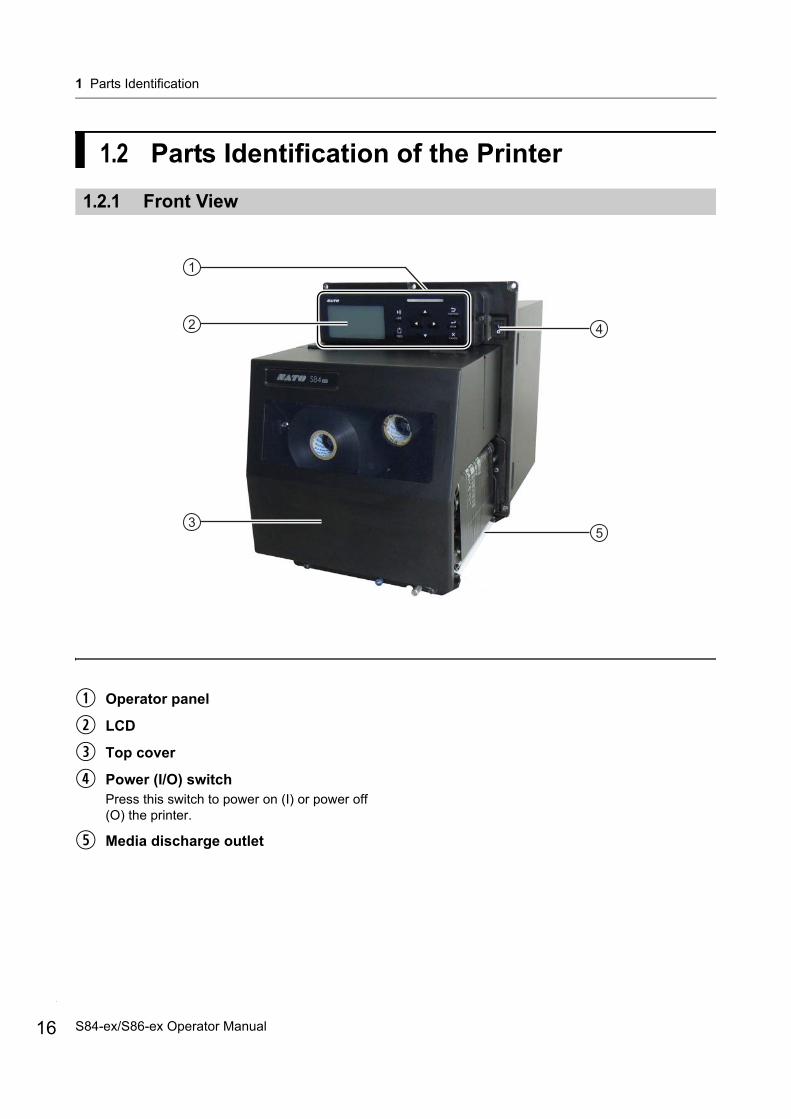
1.2.1 Front View
1
35
42
Operator panel
LCD
Top cover
Power (I/O) switchPress this switch to power on (I) or power off (O) the printer.
Media discharge outlet
S84-ex/S86-ex Operator Manual
1 Parts Identification
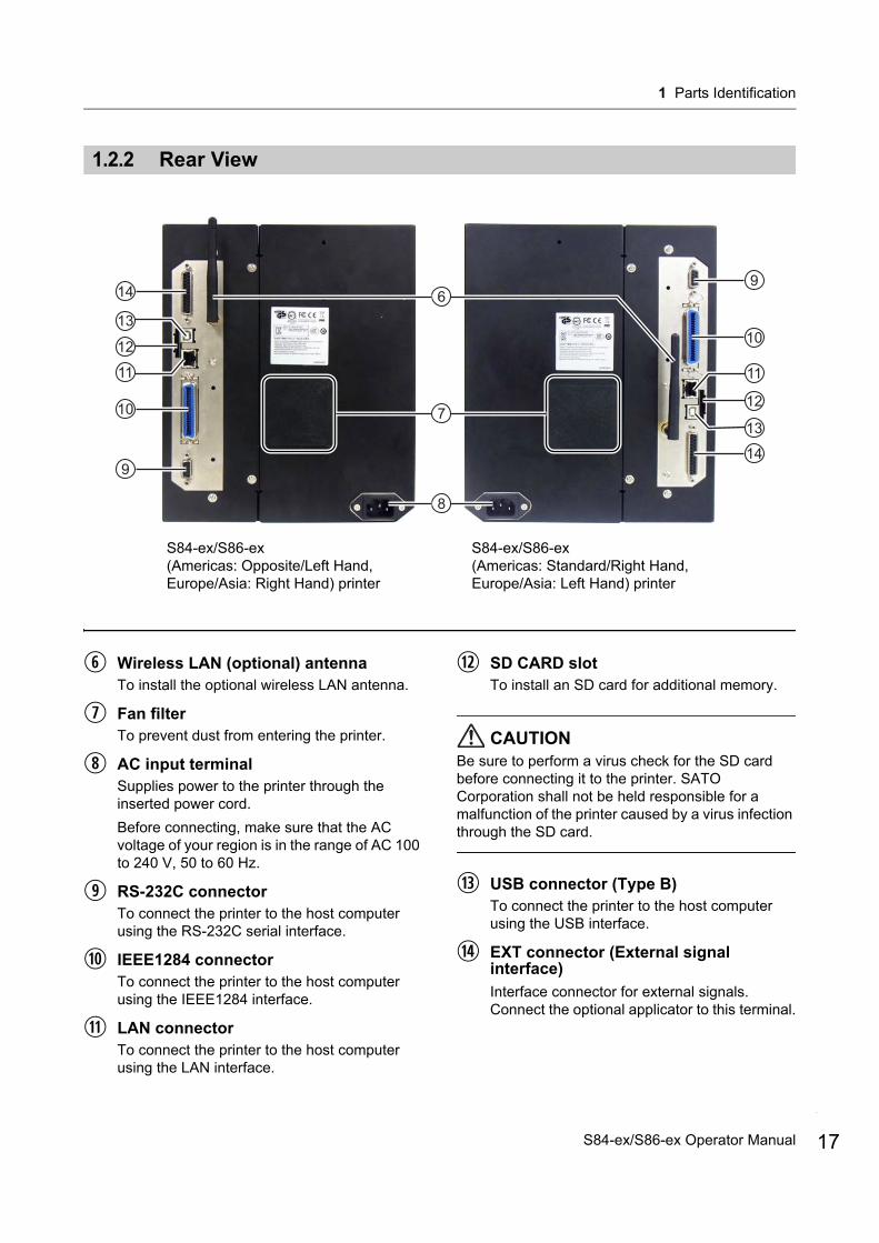
1.2.2 Rear View
6
8
10
9
7
11
12
13
14
10
9
11
12
13
14
S84-ex/S86-ex (Americas: Opposite/Left Hand,Europe/Asia: Right Hand) printer
S84-ex/S86-ex (Americas: Standard/Right Hand, Europe/Asia: Left Hand) printer
Wireless LAN (optional) antennaTo install the optional wireless LAN antenna.
Fan filterTo prevent dust from entering the printer.
AC input terminalSupplies power to the printer through the inserted power cord.
Before connecting, make sure that the AC voltage of your region is in the range of AC 100 to 240 V, 50 to 60 Hz.
RS-232C connectorTo connect the printer to the host computer using the RS-232C serial interface.
IEEE1284 connectorTo connect the printer to the host computer using the IEEE1284 interface.
LAN connectorTo connect the printer to the host computer using the LAN interface.
SD CARD slotTo install an SD card for additional memory.
CAUTIONBe sure to perform a virus check for the SD card before connecting it to the printer. SATO Corporation shall not be held responsible for a malfunction of the printer caused by a virus infection through the SD card.
USB connector (Type B)To connect the printer to the host computer using the USB interface.
EXT connector (External signal interface)
Interface connector for external signals. Connect the optional applicator to this terminal.
17S84-ex/S86-ex Operator Manual

1 Parts Identification
18
1.2.3 Internal View
15
1623
22
25
21
17
18
19
20
24
USB connector (Type A)For connecting to optional USB memory.
CAUTIONBe sure to perform a virus check for the USB memory before connecting it to the printer. SATO Corporation shall not be held responsible for a malfunction of the printer caused by a virus infection through the USB memory.
Ribbon supply spindle
Media sensor adjustment knobUsed to adjust the position of the media sensor.
Media guide
Feed lock latchUsed to open the feed roller and media sensor assembly.
Pressure roller release tabUsed to release the pressure plate.
Ribbon rewind spindle
Head lock leverUsed to release the print head assembly.
Ribbon roller
Print head (Consumables)The part to print on the media. Perform regular maintenance.
Platen roller (Consumables)
S84-ex/S86-ex Operator Manual
1 Parts Identification
1.3 Parts on the Operator Panel
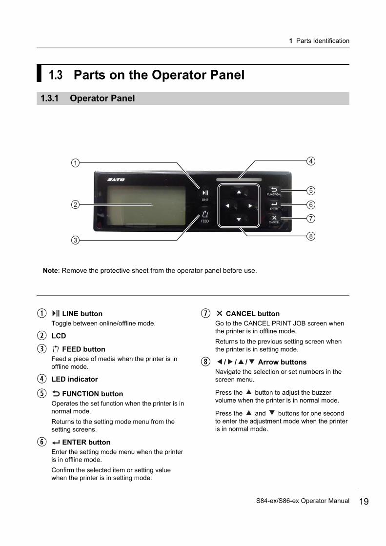
1.3.1 Operator Panel
2
3
5
41
6
7
8
Note: Remove the protective sheet from the operator panel before use.
LINE buttonToggle between online/offline mode.
LCD
FEED buttonFeed a piece of media when the printer is in offline mode.
LED indicator
FUNCTION buttonOperates the set function when the printer is in normal mode.
Returns to the setting mode menu from the setting screens.
ENTER buttonEnter the setting mode menu when the printer is in offline mode.
Confirm the selected item or setting value when the printer is in setting mode.
CANCEL buttonGo to the CANCEL PRINT JOB screen when the printer is in offline mode.
Returns to the previous setting screen when the printer is in setting mode.
/ / / Arrow buttonsNavigate the selection or set numbers in the screen menu.
Press the button to adjust the buzzer volume when the printer is in normal mode.
Press the and buttons for one second to enter the adjustment mode when the printer is in normal mode.
19S84-ex/S86-ex Operator Manual

1 Parts Identification
20
1.3.2 LED Indicator
LED Indicator Color Description
Blue Power on or online mode
(Light off) Power off or offline mode
Red Printer error (For example, when a machine error is detected)
Flashes at intervals of two seconds.
Red Printer error (For example, when the ribbon runs out)
Alternately flashes blue and red.
Blue and red
Printer error (For example, when a communication error has occurred)
S84-ex/S86-ex Operator Manual

2.1 Installation PrecautionsInstall this printer in a location as follows:
• A location that is horizontal and stable.When you install the printer onto a support structure/applicator, the complete assembly must be sturdy and stable.Attach the support structure firmly to the floor or on production machinery.
• A location that has sufficient space for operating the printer.Install the printer so that the media dispenser side is within the designated distance and height relative to the applicator.Install the media supply dispensers with an operational distance to the printer’s input side.
Do not install this printer in a location as follows. Doing so could cause the printer to malfunction.
• A location that is subject to vibration.• A location with high temperature and humidity.• A dusty location.• A location exposed to direct sunlight.• A location with a lot of electrical noise.• A location with a large fluctuation in power.
2 Installing the Printer
21S84-ex/S86-ex Operator Manual
2 Installing the Printer
22
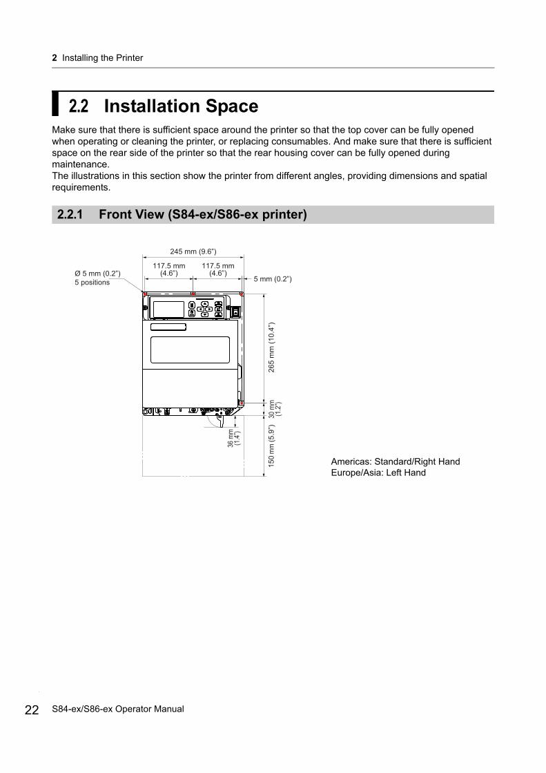
2.2 Installation SpaceMake sure that there is sufficient space around the printer so that the top cover can be fully opened when operating or cleaning the printer, or replacing consumables. And make sure that there is sufficient space on the rear side of the printer so that the rear housing cover can be fully opened during maintenance.The illustrations in this section show the printer from different angles, providing dimensions and spatial requirements.
2.2.1 Front View (S84-ex/S86-ex printer)
245 mm (9.6”)
117.5 mm(4.6”)
117.5 mm(4.6”)
5 mm (0.2”)26
5 m
m (1
0.4”
)30
mm
(1.2”
)15
0 mm
(5.9
”)Ø 5 mm (0.2”)5 positions
36 m
m(1
.4”)
Americas: Standard/Right Hand Europe/Asia: Left Hand
S84-ex/S86-ex Operator Manual
2 Installing the Printer
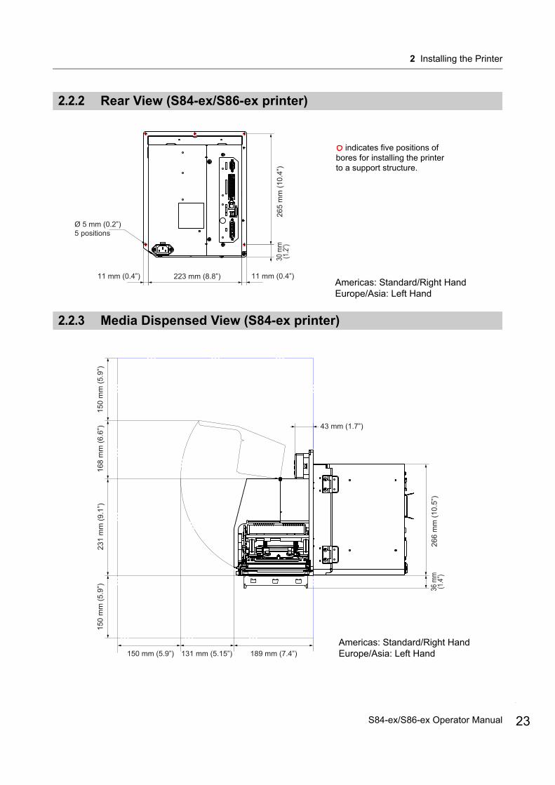
2.2.2 Rear View (S84-ex/S86-ex printer)
2.2.3 Media Dispensed View (S84-ex printer)
223 mm (8.8”) 11 mm (0.4”)11 mm (0.4”)26
5 m
m (1
0.4”
)
Ø 5 mm (0.2”)5 positions
30 m
m(1
.2”)
indicates five positions of bores for installing the printer to a support structure.
Americas: Standard/Right Hand Europe/Asia: Left Hand
150
mm
(5.9
”)15
0 m
m (5
.9”)
150 mm (5.9”)
231
mm
(9.1
”)
189 mm (7.4”)
266
mm
(10.
5”)
43 mm (1.7”)
131 mm (5.15”)
168
mm
(6.6
”)
Americas: Standard/Right Hand Europe/Asia: Left Hand
36 m
m(1
.4”)
23S84-ex/S86-ex Operator Manual
2 Installing the Printer
24
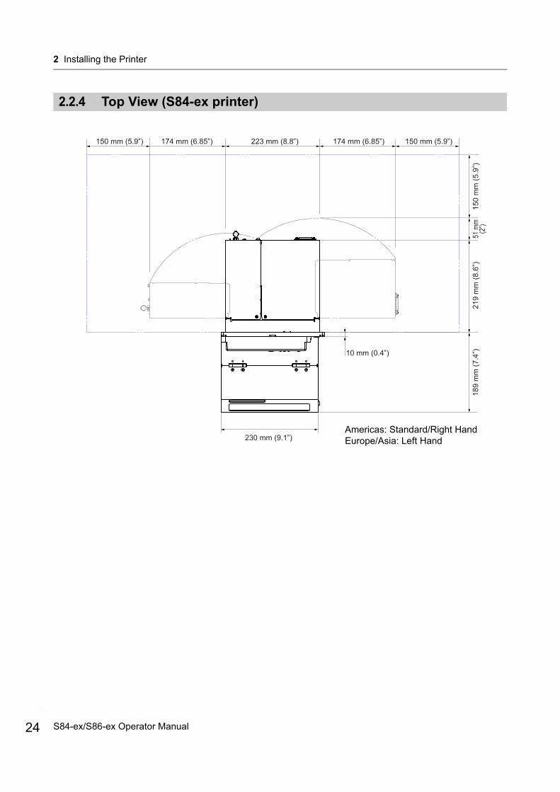
2.2.4 Top View (S84-ex printer)
230 mm (9.1”)
219
mm
(8.6
”)18
9 m
m (7
.4”)10 mm (0.4”)
51 m
m(2
”)15
0 m
m (5
.9”)
223 mm (8.8”) 174 mm (6.85”)174 mm (6.85”) 150 mm (5.9”)150 mm (5.9”)
Americas: Standard/Right Hand Europe/Asia: Left Hand
S84-ex/S86-ex Operator Manual
2 Installing the Printer
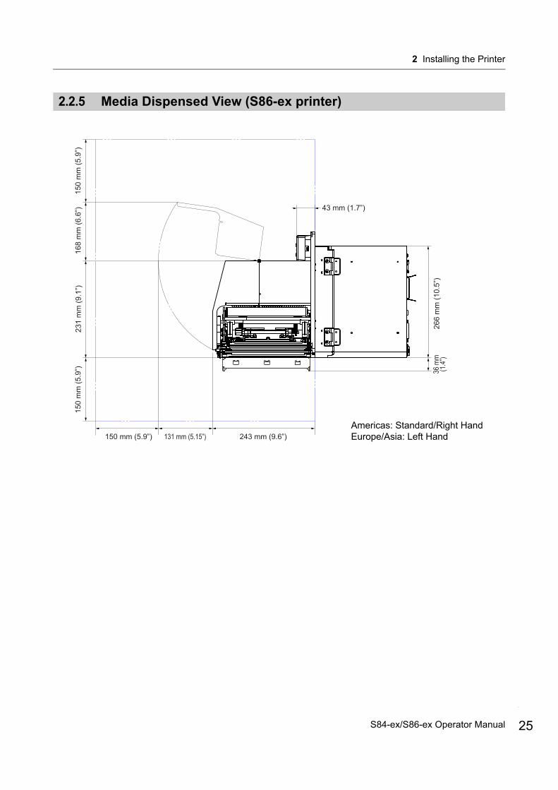
2.2.5 Media Dispensed View (S86-ex printer)
150
mm
(5.9
”)15
0 m
m (5
.9”)
150 mm (5.9”)
231
mm
(9.1
”)
243 mm (9.6”)26
6 m
m (1
0.5”
)
43 mm (1.7”)
131 mm (5.15”)
168
mm
(6.6
”)
Americas: Standard/Right Hand Europe/Asia: Left Hand
36 m
m(1
.4”)
25S84-ex/S86-ex Operator Manual
2 Installing the Printer
26
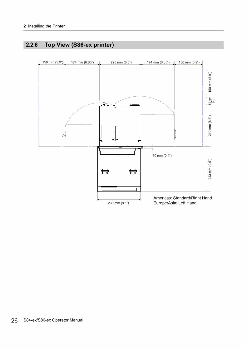
2.2.6 Top View (S86-ex printer)
51 m
m(2
”)
230 mm (9.1”)
150
mm
(5.9
”)
223 mm (8.8”) 174 mm (6.85”)174 mm (6.85”) 150 mm (5.9”)150 mm (5.9”)
219
mm
(8.6
”)24
3 m
m (9
.6”)
10 mm (0.4”)
Americas: Standard/Right Hand Europe/Asia: Left Hand
S84-ex/S86-ex Operator Manual
2 Installing the Printer
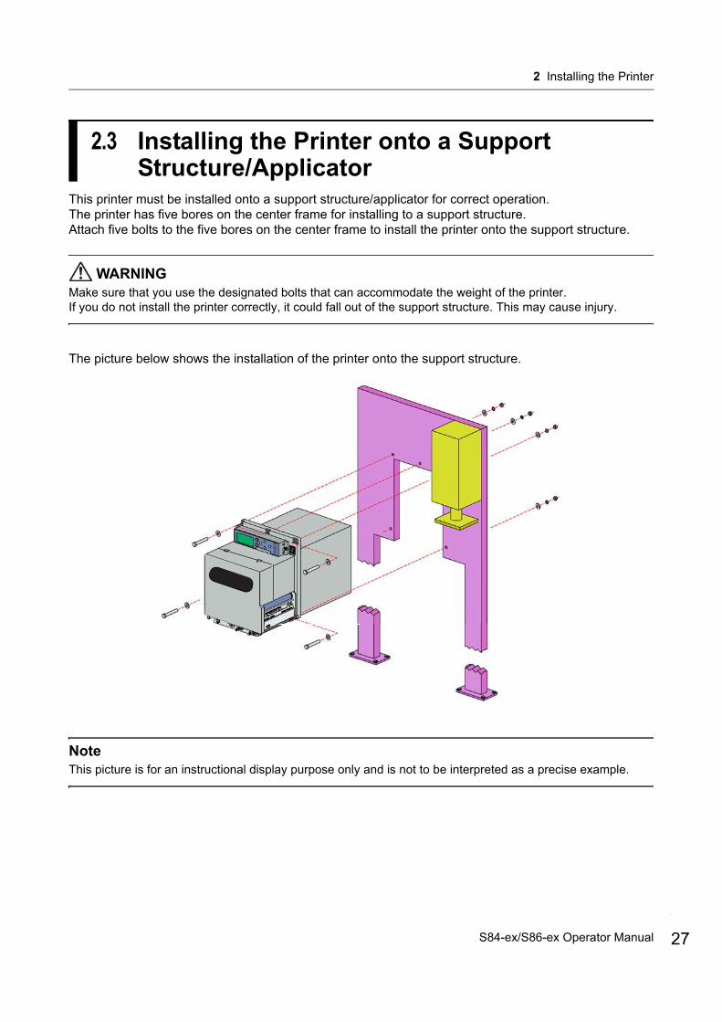
2.3 Installing the Printer onto a Support Structure/Applicator
This printer must be installed onto a support structure/applicator for correct operation.The printer has five bores on the center frame for installing to a support structure. Attach five bolts to the five bores on the center frame to install the printer onto the support structure.
WARNINGMake sure that you use the designated bolts that can accommodate the weight of the printer.If you do not install the printer correctly, it could fall out of the support structure. This may cause injury.
The picture below shows the installation of the printer onto the support structure.
NoteThis picture is for an instructional display purpose only and is not to be interpreted as a precise example.
27S84-ex/S86-ex Operator Manual

2 Installing the Printer
28
2.4 Checking the Bundled AccessoriesAfter unpacking the printer, make sure that you have all the bundled accessories. If there are missing items, contact the SATO reseller where you purchased the printer.
NoteKeep the packaging box and cushioning material after installing the printer. You can pack the printer with this packaging box for shipment when requesting for repairs.
User documents(Quick guide, Warranty, etc.)
Ribbon core
* The shape of power plug varies depending on the region in which it was purchased.
14-pin conversion cableAC power cord*
S84-ex/S86-ex Operator Manual

2 Installing the Printer
2.5 Connecting the Interface CableThe connection of the interface cable is explained as follows:
2.5.1 Available Interfaces
This printer supports the following interfaces.Furthermore, a printer connected with multiple interface cables can continue to operate when receiving data.*You cannot receive data from more than one interface at a time.*You cannot use the USB interface if you have installed the optional wireless LAN.
• USB• LAN• RS-232C• IEEE1284• Bluetooth• Wireless LAN (WLAN)• External signal (EXT)
NoteThe wireless LAN interface and Bluetooth interface are optional.
2.5.2 Interface Connections
1 Make sure that the printer, host computer and applicator are powered off.Set the power switch of the printer to the “O” position.
2 Connect the printer to a host computer with one or more of the available interface connections.Use a cable that is compatible with the standard of the interface board as stated in Section 8.13 Interface Specifications. Check the orientation of the connector before you make the connection.
Applicator
Host computer
29S84-ex/S86-ex Operator Manual
2 Installing the Printer
30
3 Connect the applicator cable from the EXT connector of the printer to the applicator.Use a cable that is compatible with the standard of the interface board as stated in Section 8.13 Interface Specifications. Check the orientation of the connector before you make the connection.
CAUTIONDo not connect or disconnect the interface cables (or use a switch box) with power supplied to either the printer or computer. This action may cause damage to the interface circuitry in the printer or computer. The warranty does not cover such damages.
2.5.3 Interface Settings
You can set the various interface settings of the printer through the interface mode menu. For details, refer to Section 4.2.10 Interface Mode.
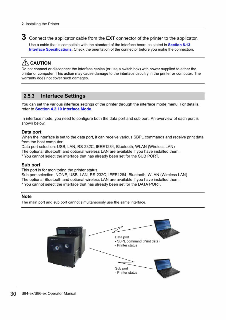
In interface mode, you need to configure both the data port and sub port. An overview of each port is shown below.
Data portWhen the interface is set to the data port, it can receive various SBPL commands and receive print data from the host computer.Data port selection: USB, LAN, RS-232C, IEEE1284, Bluetooth, WLAN (Wireless LAN)The optional Bluetooth and optional wireless LAN are available if you have installed them.* You cannot select the interface that has already been set for the SUB PORT.
Sub portThis port is for monitoring the printer status. Sub port selection: NONE, USB, LAN, RS-232C, IEEE1284, Bluetooth, WLAN (Wireless LAN)The optional Bluetooth and optional wireless LAN are available if you have installed them.* You cannot select the interface that has already been set for the DATA PORT.
NoteThe main port and sub port cannot simultaneously use the same interface.
Sub port- Printer status
Data port- SBPL command (Print data)- Printer status
S84-ex/S86-ex Operator Manual

2 Installing the Printer
2.5.4 Interface Combination
The interface combinations that can be used for the data port and sub port are as follows.
[o: configurable, x: not configurable]
Note• The optional Bluetooth and optional wireless LAN are available if you have installed them.• Do not select the same interface for the data port and sub port.• If you have installed the optional wireless LAN, you cannot use the USB interface. The optional wireless
LAN is connected to the printer through the USB.• The sub port cannot be used if you have set ENABLE in the INTERFACE AUTO SELECT screen.• When WLAN is configured for the data port or sub port, but the printer is powered on without the wireless
LAN adapter, the configured interface setting is changed from WLAN to USB. When USB is configured as the data port or sub port, but the wireless LAN adapter is connected, the configured interface setting is changed from USB to WLAN.
Data Port
USB LAN RS-232C IEEE1284 Bluetooth WLAN
Su
b P
ort
USB x o o o o x
LAN o x o o o o
RS-232C o o x o o o
IEEE1284 o o o x o o
Bluetooth o o o o x o
WLAN x o o o o x
NONE o o o o o o
31S84-ex/S86-ex Operator Manual
2 Installing the Printer
32
2.6 Connecting the Power Cord
WARNING• Do not touch the power switch, connect or disconnect the power cord while your hands are wet. Doing so
could cause an electric shock.• Always connect the ground wire to a ground terminal. Electric shock could occur if you do not.
Note• The attached power cord is designed exclusively for this printer.• Do not use the attached power cord with other devices.
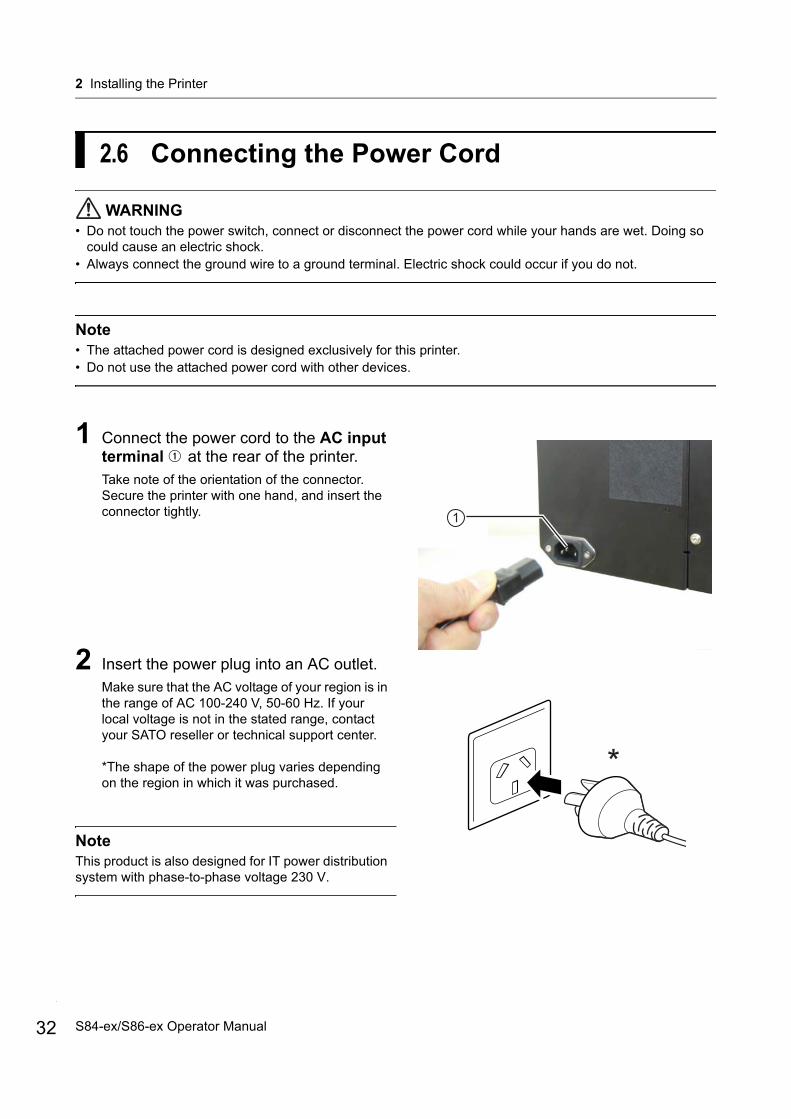
1 Connect the power cord to the AC input terminal at the rear of the printer.Take note of the orientation of the connector. Secure the printer with one hand, and insert the connector tightly.
2 Insert the power plug into an AC outlet.Make sure that the AC voltage of your region is in the range of AC 100-240 V, 50-60 Hz. If your local voltage is not in the stated range, contact your SATO reseller or technical support center.
*The shape of the power plug varies depending on the region in which it was purchased.
NoteThis product is also designed for IT power distribution system with phase-to-phase voltage 230 V.
1
*
S84-ex/S86-ex Operator Manual
2 Installing the Printer
2.7 Power On/Off the Printer
WARNINGDo not touch the power switch, connect or disconnect the power cord while your hands are wet. Doing so could cause an electric shock.
CAUTIONDo not power off the printer during operation, such as when printing or updating. Doing so could cause a malfunction of the printer.
2.7.1 Power On the Printer
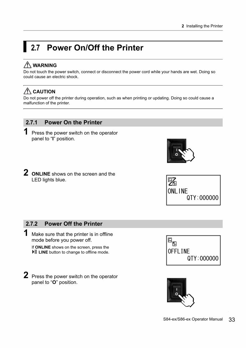
1 Press the power switch on the operator panel to “I” position.
2 ONLINE shows on the screen and the LED lights blue.
2.7.2 Power Off the Printer
1 Make sure that the printer is in offline mode before you power off.If ONLINE shows on the screen, press the
LINE button to change to offline mode.
2 Press the power switch on the operator panel to “O” position.
33S84-ex/S86-ex Operator Manual

2 Installing the Printer
34
2.8 Installing Optional Memory StorageThe optional SD card or USB memory can be used for uploading and downloading data (print format, graphics, extended characters) registered in the printer and printer firmware.Contact your SATO reseller or service center for the recommended SD card or USB memory.
CAUTIONBe sure to perform a virus check for the USB memory or SD card before connecting it to the printer. SATO Corporation shall not be held responsible for a malfunction of the printer caused by a virus infection through the USB memory or SD card.
2.8.1 Installing the Optional SD Card
You can install an optional SD card into the SD card slot located on the rear of the printer.When using the SD card for the first time, format the SD card in the memory card mode. Refer to Section 4.2.11 Memory Mode for details.
1 Power off the printer.
2 Insert the optional SD card into the SD card slot with the orientation the same as shown in the picture.Contact your SATO reseller for the recommended SD card.
3 To seat the SD card in the SD card slot, push it in until it makes a slight clicking sound and is almost completely inside the printer.When seated and ready to operate, only a very small portion protrudes, approximately 3.18 mm (0.125”).
2
1
S84-ex/S86-ex Operator Manual

2 Installing the Printer
2.8.2 Removing the Optional SD Card
1 Power off the printer.
2 Press the card edge slightly to release the SD card from the SD card slot. The SD card slot will immediately release the SD card .
CAUTIONDo not remove the SD card while the printer is accessing the data in the SD card. Doing so may result in data corruption.
2.8.3 Installing the Optional USB Memory
When using the USB memory for the first time, format the USB memory in the memory card mode. Refer to Section 4.2.11 Memory Mode for details.
1 Power off the printer.
2 Open the top cover.
3 Insert the optional USB memory into the USB connector (Series A plug, 2.0 High-speed) on the front of the printer.Contact your SATO reseller for the recommended USB memory.
4 Close the top cover.
To remove the USB memory from the printerPower off the printer before removing the USB memory.
CAUTIONDo not remove the USB memory while the printer is accessing the data in the USB memory. Doing so may result in data corruption.
1
1
2
35S84-ex/S86-ex Operator Manual
2 Installing the Printer
36
This page is intentionally left blank.
S84-ex/S86-ex Operator Manual
+
This printer supports two types of print methods, namely thermal transfer and direct thermal. Thermal transfer is a print method that transfers the ink of the ribbon to the media. Direct thermal is a print method that creates the image on direct thermal media. Ribbon is not necessary if you are using direct thermal media.
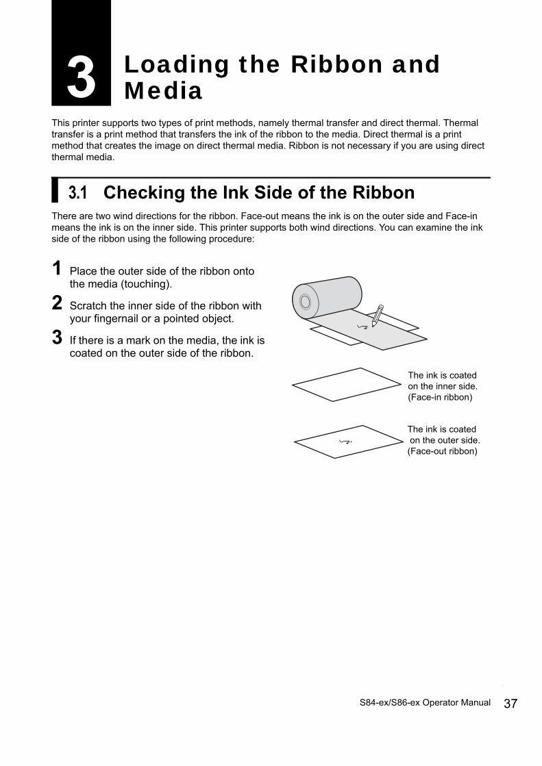
3.1 Checking the Ink Side of the RibbonThere are two wind directions for the ribbon. Face-out means the ink is on the outer side and Face-in means the ink is on the inner side. This printer supports both wind directions. You can examine the ink side of the ribbon using the following procedure:
1 Place the outer side of the ribbon onto the media (touching).
2 Scratch the inner side of the ribbon with your fingernail or a pointed object.
3 If there is a mark on the media, the ink is coated on the outer side of the ribbon.
3 Loading the Ribbon and Media
The ink is coated on the inner side.(Face-in ribbon)
The ink is coated on the outer side.(Face-out ribbon)
37S84-ex/S86-ex Operator Manual
3 Loading the Ribbon and Media
38
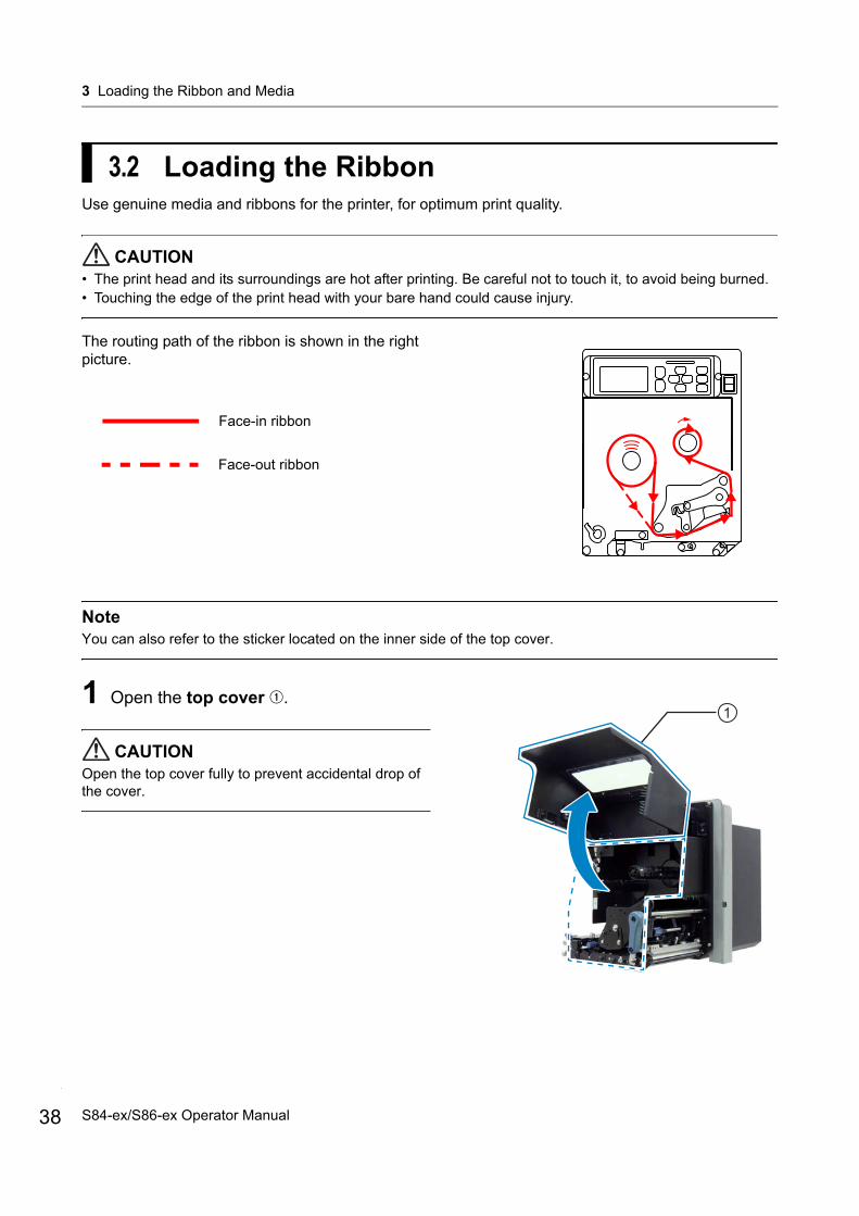
3.2 Loading the RibbonUse genuine media and ribbons for the printer, for optimum print quality.
CAUTION• The print head and its surroundings are hot after printing. Be careful not to touch it, to avoid being burned.• Touching the edge of the print head with your bare hand could cause injury.
The routing path of the ribbon is shown in the right picture.
NoteYou can also refer to the sticker located on the inner side of the top cover.
1 Open the top cover .
CAUTIONOpen the top cover fully to prevent accidental drop of the cover.
Face-in ribbon
Face-out ribbon
1
S84-ex/S86-ex Operator Manual

3 Loading the Ribbon and Media
2 Turn the head lock lever clockwise to unlock the print head.
3 Load the ribbon onto the ribbon supply spindle . While taking note of the wind direction, insert the ribbon all the way in.Make sure that the ink side of the ribbon is facing down when passing it below the print head.
4 Load an empty ribbon core onto the ribbon rewind spindle . Insert the core all the way in.
2
46
5
3
39S84-ex/S86-ex Operator Manual

3 Loading the Ribbon and Media
40
5 From the ribbon supply spindle , pass the ribbon below the print head and to the ribbon rewind spindle .
6 Wind the ribbon clockwise around the empty ribbon core on the ribbon rewind spindle . Attach the free end of the ribbon to the core with adhesive tape .
7 Turn the ribbon rewind spindle clockwise for several rounds, to wind the ribbon.
8 If the media is already loaded, turn the head lock lever counterclockwise to lock the print head. If the media is not loaded, continue with Section 3.5 Loading Media.
9 Close the top cover.
46
7
8
6
2
S84-ex/S86-ex Operator Manual
3 Loading the Ribbon and Media
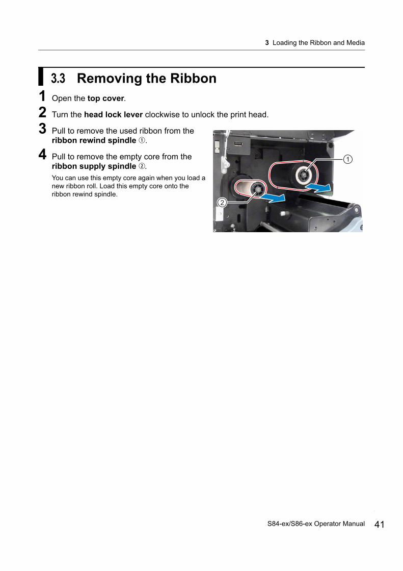
3.3 Removing the Ribbon1 Open the top cover.
2 Turn the head lock lever clockwise to unlock the print head.
3 Pull to remove the used ribbon from the ribbon rewind spindle .
4 Pull to remove the empty core from the ribbon supply spindle .You can use this empty core again when you load a new ribbon roll. Load this empty core onto the ribbon rewind spindle.
1
2
41S84-ex/S86-ex Operator Manual

3 Loading the Ribbon and Media
42
3.4 Usable MediaThis printer can print on two types of media; media roll and fan-fold media. The printer uses media sensors to detect I-marks or Gaps on the media in order to precisely print the content.
3.4.1 Adjusting the Position of the Media Sensor
Non-standard media are media with printing on the reverse side, or media with special shapes. When using non-standard media, make sure that the media sensor position is aligned with the I-mark or gap of the media.The I-mark sensor of the printer has a fixed position of 5 mm (0.2”) measured from the printer’s center frame.The position of the gap sensor is adjustable. You can adjust the gap sensor position in the following range.S84-ex printer: 5 mm to 66 mm (0.2” to 2.6”) measured from the printer’s center frame.S86-ex printer: 5 mm to 81 mm (0.2” to 3.2”) measured from the printer’s center frame.
1 Open the top cover.
2 Turn the media sensor adjustment knob clockwise or counterclockwise to adjust the gap sensor position.The green indicator on top of the media sensor assembly shows the position of the gap sensor.
14 mm(0.55”)
1.5 mm (0.06”)
I-mark journal paper/linerless labelGap labelI-mark label
3 mm (0.12”)
3 mm(0.12”)
3 mm(0.12”)
1.5 mm (0.06”)
14 mm(0.55”)
3 mm(0.12”)
Med
ia fe
eddi
rect
ion
Med
ia fe
eddi
rect
ion
Med
ia fe
eddi
rect
ion
1
2
S84-ex/S86-ex Operator Manual
3 Loading the Ribbon and Media
3.5 Loading MediaUse genuine media and ribbons for the printer, for optimum print quality.
CAUTION• The print head and its surroundings are hot after printing. Be careful not to touch it, to avoid being burned.• Touching the edge of the print head with your bare hand could cause injury.
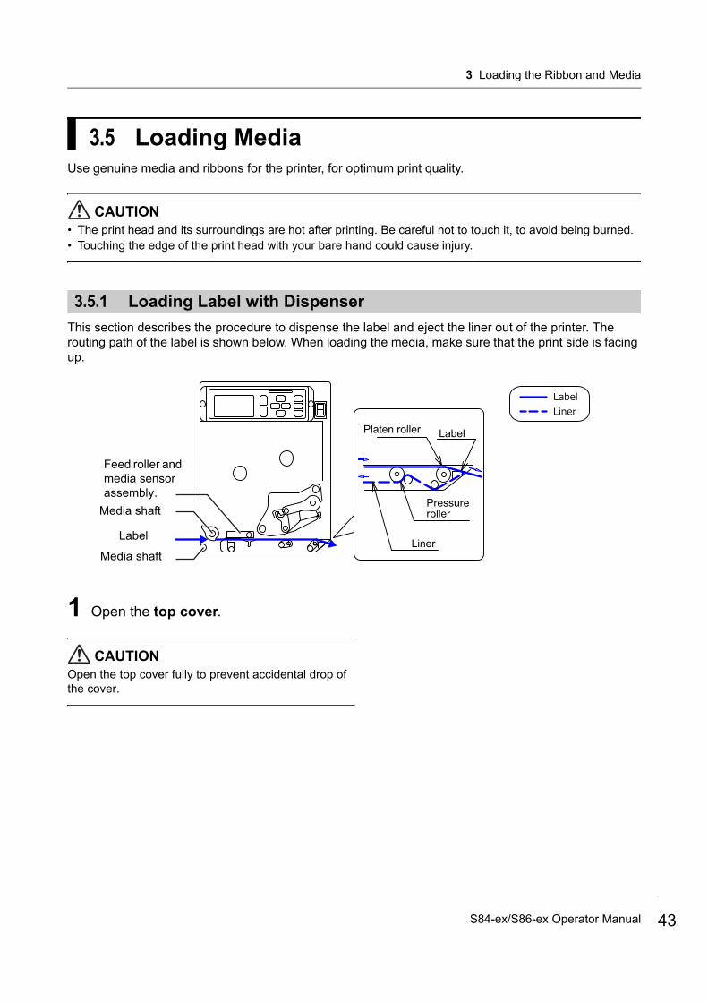
3.5.1 Loading Label with Dispenser
This section describes the procedure to dispense the label and eject the liner out of the printer. The routing path of the label is shown below. When loading the media, make sure that the print side is facing up.
1 Open the top cover.
CAUTIONOpen the top cover fully to prevent accidental drop of the cover.
LabelPlaten roller
Pressure roller
Liner
Feed roller and media sensor assembly.
Media shaft
Media shaft
Label
43S84-ex/S86-ex Operator Manual
3 Loading the Ribbon and Media
44
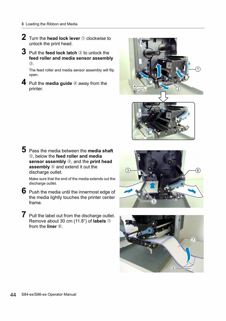
2 Turn the head lock lever clockwise to unlock the print head.
3 Pull the feed lock latch to unlock the feed roller and media sensor assembly .The feed roller and media sensor assembly will flip open.
4 Pull the media guide away from the printer.
5 Pass the media between the media shaft , below the feed roller and media sensor assembly , and the print head assembly and extend it out the discharge outlet. Make sure that the end of the media extends out the discharge outlet.
6 Push the media until the innermost edge of the media lightly touches the printer center frame.
7 Pull the label out from the discharge outlet. Remove about 30 cm (11.8”) of labels from the liner .
1
42
3
5
3 6
8
7
S84-ex/S86-ex Operator Manual
3 Loading the Ribbon and Media
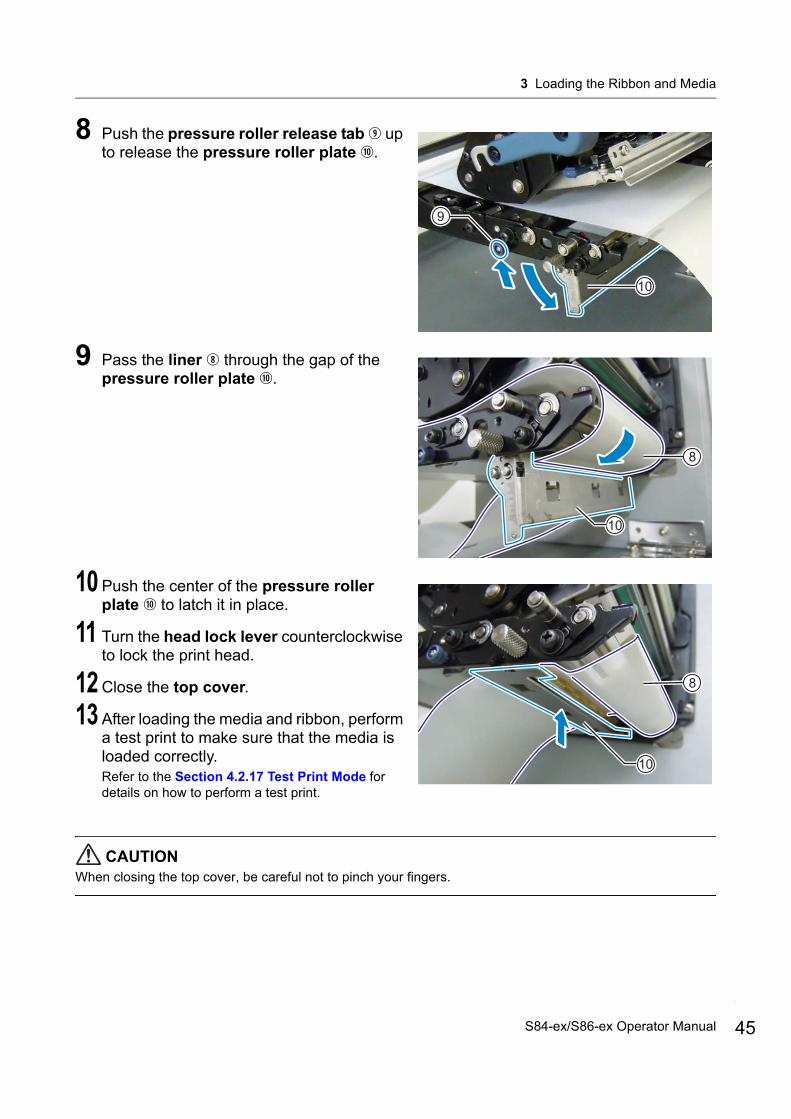
8 Push the pressure roller release tab up to release the pressure roller plate .
9 Pass the liner through the gap of the pressure roller plate .
10 Push the center of the pressure roller plate to latch it in place.
11 Turn the head lock lever counterclockwise to lock the print head.
12 Close the top cover.
13 After loading the media and ribbon, perform a test print to make sure that the media is loaded correctly.Refer to the Section 4.2.17 Test Print Mode for details on how to perform a test print.
CAUTIONWhen closing the top cover, be careful not to pinch your fingers.
9
10
10
8
8
10
45S84-ex/S86-ex Operator Manual

3 Loading the Ribbon and Media
46
3.5.2 Loading Media without Using Dispenser
This section describes the procedure to just load the media without using the dispenser. The routing path of the media is shown in the right picture. When loading the media, make sure that the print side is facing up.
1 Refer to steps 1 through 6 of Section 3.5.1 Loading Label with Dispenser to load the media.
2 Turn the head lock lever counterclockwise to lock the print head.
3 Press the feed roller and media sensor assembly down until the feed lock latch is locked.
4 Push the media guide lightly against the outermost edge of the media.
5 Close the top cover.
6 After loading the media and ribbon, perform a test print to make sure that the media is loaded correctly.Refer to the Section 4.2.17 Test Print Mode for details on how to perform a test print.
CAUTIONWhen closing the top cover, be careful not to pinch your fingers.
Feed roller and media sensor assembly.
Media shaft
Media shaft
Media
2
3
14
S84-ex/S86-ex Operator Manual

93
4.1 Display and OperationThe display of the printer varies depending on the following modes:• Normal mode: refer to Section 4.1.1 Normal Mode Display and Icons.• Setting mode menu: refer to Section 4.1.2 Setting Mode Menu and Icons.• Error display: refer to Section 4.1.3 Error Display and Icons.• Setting display: refer to Section 4.1.4 Setting Display.
4.1.1 Normal Mode Display and Icons
In normal mode, the screen shows the following printer status.
• Printer mode
4 Operation and Configuration
Icon Description
Shows when the printer is in online mode.
Shows when the printer is in offline mode.
Shows when the printer is in test print mode and hex dump print mode.
Shows when the printer is in download mode.
Shows when the printer is in upload mode.
Shows when the printer is in memory mode.
Printer mode icon
Trace mode status icon,WLAN field intensitystatus icon or Bluetoothconnection status icon
Message display
SD card icon
USB memory icon
Buzzer volume icon or emulation icon when emulation module is loaded
Warning icons
47S84-ex/S86-ex Operator Manual

4 Operation and Configuration
48
• Trace mode status
• WLAN field intensity status
• Bluetooth connection status
Icon Description
Shows after receiving any data while trace mode is ENABLE.
Shows after receiving ESC (1BH) A while trace mode is ENABLE.
Shows after print operation while trace mode is ENABLE.
Icon DescriptionInfrastructure Mode
Ad Hoc Mode
The meaning of this icon differs depending on the wireless LAN mode.In Infrastructure modeShows when the field intensity is more than level 3 and the printer is connected to an access point.In Ad Hoc modeAlways shows when the printer is connected.
O O
Shows when the field intensity is between levels 2 and 3, and the printer is connected to an access point.
O Not used
Shows when the field intensity is between levels 1 and 2, and the printer is connected to an access point.
O Not used
The meaning of this icon differs depending on the wireless LAN mode.In Infrastructure modeShows when the field intensity is less than level 1 and the printer is connected to an access point.However, it may be possible to communicate depending on the environment.In Ad Hoc modeAlways shows when the printer is not connected.
O O
Shows when the printer is not connected to an access point. O Not used
Icon Description
Shows when Bluetooth is connected.
Shows when Bluetooth is disconnected.
S84-ex/S86-ex Operator Manual

4 Operation and Configuration
• Buzzer volume
• Emulation mode
• Warning Icons
Icon Description
Shows when the volume is level 3 (Loud).
Shows when the volume is level 2 (Medium).
Shows when the volume is level 1 (Low).
Shows when the volume is level 0 (Mute).
Icon Description
Shows when SZPL emulation module is loaded.
Shows when SDPL emulation module is loaded.
Shows when SIPL emulation module is loaded.
Icon Description
Shows when a ribbon “near end” is detected.
Shows when a label “near end” is detected.
Shows when a command error is detected.
Shows when a receive buffer “near full” is detected.
Shows when print head damage is detected.
Shows when an incompatible print head is detected.
49S84-ex/S86-ex Operator Manual

4 Operation and Configuration
50
• Memory card status
Icon Description
Shows when an SD card is inserted.
Shows when a USB memory is inserted.
Note• These icons show when the SD card or USB memory is connected.• These icons do not show when the printer is in an error mode.• These icons do not show when the trace mode is enabled.• These icons do not show when the ESC+IM command (for specifying LCD display) is in use.• These icon colors are inverted when the SD card or USB memory is being accessed.
S84-ex/S86-ex Operator Manual
4 Operation and Configuration
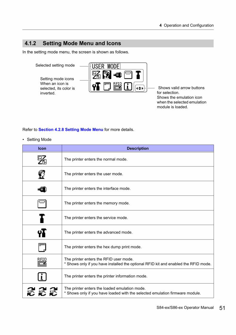
4.1.2 Setting Mode Menu and Icons
In the setting mode menu, the screen is shown as follows.
Refer to Section 4.2.8 Setting Mode Menu for more details.
• Setting Mode
Icon Description
The printer enters the normal mode.
The printer enters the user mode.
The printer enters the interface mode.
The printer enters the memory mode.
The printer enters the service mode.
The printer enters the advanced mode.
The printer enters the hex dump print mode.
The printer enters the RFID user mode.* Shows only if you have installed the optional RFID kit and enabled the RFID mode.
The printer enters the printer information mode.
The printer enters the loaded emulation mode.* Shows only if you have loaded with the selected emulation firmware module.
Setting mode iconsWhen an icon is selected, its color is inverted.
Selected setting mode
Shows valid arrow buttons for selection.Shows the emulation icon when the selected emulation module is loaded.
51S84-ex/S86-ex Operator Manual
4 Operation and Configuration
52
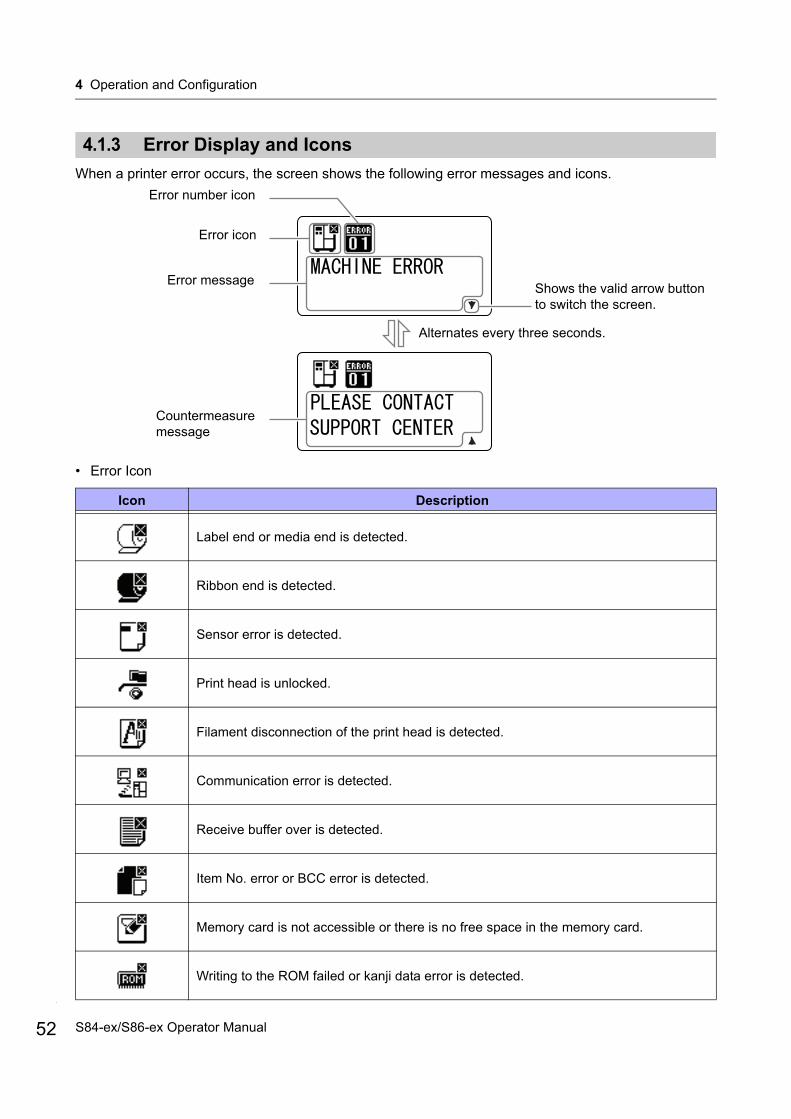
4.1.3 Error Display and Icons
When a printer error occurs, the screen shows the following error messages and icons.
• Error Icon
Icon Description
Label end or media end is detected.
Ribbon end is detected.
Sensor error is detected.
Print head is unlocked.
Filament disconnection of the print head is detected.
Communication error is detected.
Receive buffer over is detected.
Item No. error or BCC error is detected.
Memory card is not accessible or there is no free space in the memory card.
Writing to the ROM failed or kanji data error is detected.
Error message
Countermeasure message
Alternates every three seconds.
Error number icon
Error icon
Shows the valid arrow button to switch the screen.
S84-ex/S86-ex Operator Manual
4 Operation and Configuration
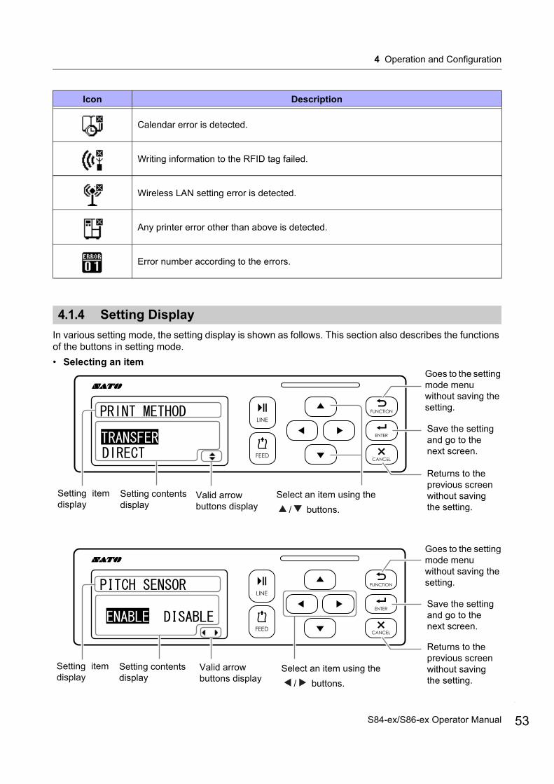
4.1.4 Setting Display
In various setting mode, the setting display is shown as follows. This section also describes the functions of the buttons in setting mode.
• Selecting an item
Calendar error is detected.
Writing information to the RFID tag failed.
Wireless LAN setting error is detected.
Any printer error other than above is detected.
Error number according to the errors.
Icon Description
Select an item using the
/ buttons.
Returns to the previous screen without saving the setting.
Save the setting and go to the next screen.
Goes to the setting mode menu without saving the setting.
Setting contents display
Setting itemdisplay
Select an item using the
/ buttons.
Valid arrow buttons display
Valid arrow buttons display
Setting contents display
Setting itemdisplay
Returns to the previous screen without saving the setting.
Save the setting and go to the next screen.
Goes to the setting mode menu without saving the setting.
53S84-ex/S86-ex Operator Manual

4 Operation and Configuration
54
• Setting values
Setting contents display
Setting itemdisplay
Valid arrow buttons display
Move the cursor
using the / buttons.
Change the value of the highlighted cursor
using the / buttons.
Save the value and go to the next screen.
Goes to the setting mode menu without saving the setting.
Returns to the previous screen without saving the setting.
S84-ex/S86-ex Operator Manual

4 Operation and Configuration
4.2 Operating ModesThe printer contains a variety of the following operating modes:Click on the blue links below to go directly to the details of the selected operating mode.
• Online Mode/Pause Mode/Offline Mode
• Adjusting the Display Brightness
• Adjusting the Buzzer Volume
• Canceling the Print Job
• Adjustment Mode
• Work Shift Setting Mode
• Simple Standalone Mode
• Setting Mode Menu:
• User Mode
• Interface Mode
• Memory Mode
• Service Mode
• Advanced Mode
• Hex Dump Mode
• RFID User Mode
• Information Mode
• Test Print Mode
• Default Setting Mode
• Download Mode
• Upload Mode
• Hidden Setting Mode
• Wireless LAN Certificate Download Mode
• Site Survey Mode
55S84-ex/S86-ex Operator Manual
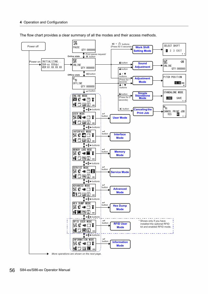
4 Operation and Configuration
56
The flow chart provides a clear summary of all the modes and their access methods.
Power off
buttons
Online state
Power on
Offline state
User mode
Interface mode
Advanced mode
HEX dumpmode
More operations are shown on the next page.
button
button
Soundadjustment mode
Work shiftsetting mode
Memory cardmode
RFID usermode
Informationmode
Service mode
Print pause request/button
Simplestandalone mode
Adjustment mode
Cancel print jobmode
button
button
(Press for 5 seconds)
button(Press for 5seconds)
button
buttons+
button
button
button
button
button
button
button
button
buttons
buttons
buttons
buttons
buttons
buttons
buttons
* Shows only if you have installed the optional RFID kit and enabled RFID mode.
(Press for 1second)
buttons+
buttons+
User Mode
Adjustment Mode
Sound Adjustment
Interface Mode
Memory Mode
Service Mode
Advanced Mode
Hex Dump Mode
Information Mode
Work Shift Setting Mode
Simple Standalone
Mode
Canceling the Print Job
Hex Dump Mode
RFID User Mode
S84-ex/S86-ex Operator Manual
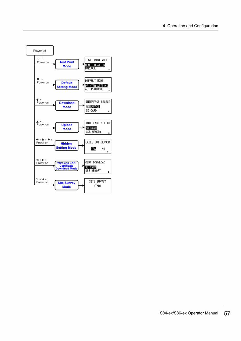
4 Operation and Configuration
Power on
Power off
Test print mode
Power on Default settingmode
Downloadmode
+Power on
Uploadmode
+Power on
+
+
Hidden settingmode
+ + +Power on
WLAN certificatedownload mode
+ +Power on
Site surveymode
+ +Power on
Test Print Mode
Default Setting Mode
Download Mode
Hidden Setting Mode
Upload Mode
Wireless LAN Certificate
Download Mode
Site Survey Mode
57S84-ex/S86-ex Operator Manual
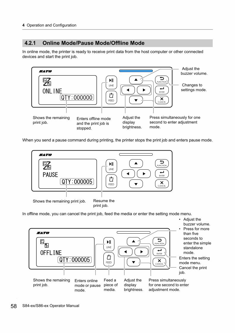
4 Operation and Configuration
58
4.2.1 Online Mode/Pause Mode/Offline Mode
In online mode, the printer is ready to receive print data from the host computer or other connected devices and start the print job.
When you send a pause command during printing, the printer stops the print job and enters pause mode.
In offline mode, you can cancel the print job, feed the media or enter the setting mode menu.
Enters offline mode and the print job is stopped.
Changes to settings mode.
Adjust the display brightness.
Adjust the buzzer volume.
Press simultaneously for one second to enter adjustment mode.
Shows the remaining print job.
Shows the remaining print job. Resume the print job.
Enters online mode or pause mode.
Feed a piece of media.
Adjust the display brightness.
Shows the remaining print job.
Press simultaneously for one second to enter adjustment mode.
• Adjust the buzzer volume.
• Press for more than five seconds to enter the simple standalone mode.
Cancel the print job.
Enters the setting mode menu.
S84-ex/S86-ex Operator Manual
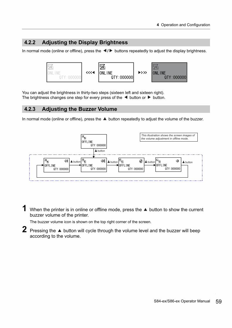
4 Operation and Configuration
4.2.2 Adjusting the Display Brightness
In normal mode (online or offline), press the / buttons repeatedly to adjust the display brightness.
You can adjust the brightness in thirty-two steps (sixteen left and sixteen right).The brightness changes one step for every press of the button or button.
4.2.3 Adjusting the Buzzer Volume
In normal mode (online or offline), press the button repeatedly to adjust the volume of the buzzer.
1 When the printer is in online or offline mode, press the button to show the current buzzer volume of the printer.The buzzer volume icon is shown on the top right corner of the screen.
2 Pressing the button will cycle through the volume level and the buzzer will beep according to the volume.
button
button button button button
This illustration shows the screen images of the volume adjustment in offline mode.
59S84-ex/S86-ex Operator Manual
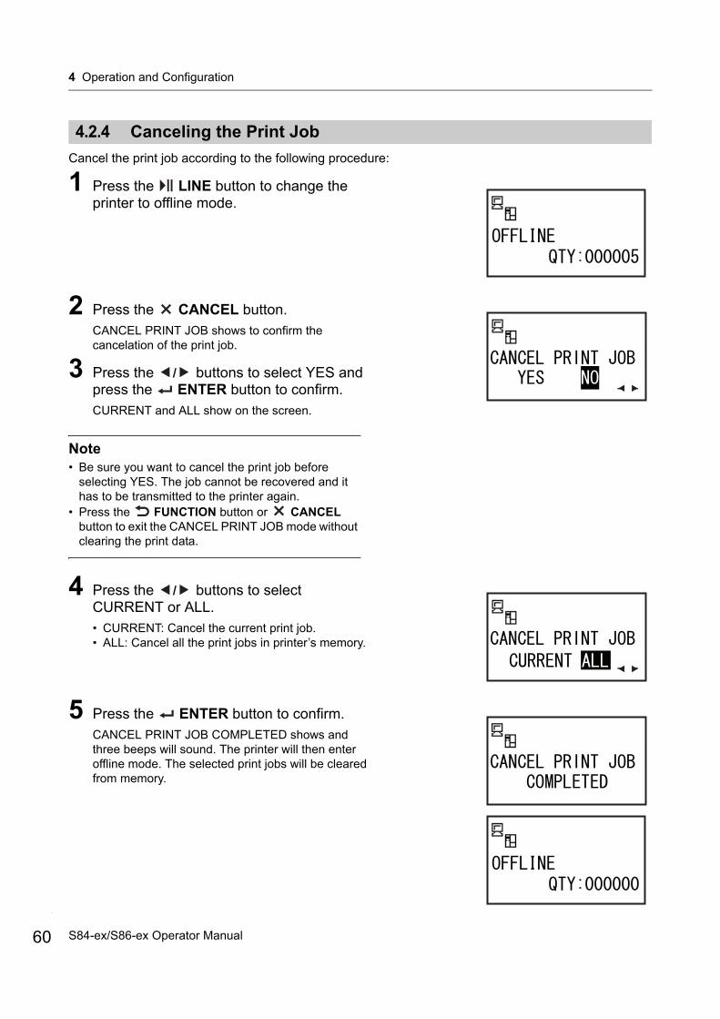
4 Operation and Configuration
60
4.2.4 Canceling the Print Job
Cancel the print job according to the following procedure:
1 Press the LINE button to change the printer to offline mode.
2 Press the CANCEL button.CANCEL PRINT JOB shows to confirm the cancelation of the print job.
3 Press the / buttons to select YES and press the ENTER button to confirm.CURRENT and ALL show on the screen.
Note• Be sure you want to cancel the print job before
selecting YES. The job cannot be recovered and it has to be transmitted to the printer again.
• Press the FUNCTION button or CANCEL button to exit the CANCEL PRINT JOB mode without clearing the print data.
4 Press the / buttons to select CURRENT or ALL.• CURRENT: Cancel the current print job.• ALL: Cancel all the print jobs in printer’s memory.
5 Press the ENTER button to confirm. CANCEL PRINT JOB COMPLETED shows and three beeps will sound. The printer will then enter offline mode. The selected print jobs will be cleared from memory.
S84-ex/S86-ex Operator Manual

4 Operation and Configuration
4.2.5 Adjustment Mode
The printer has a quick access to the adjustment mode for setting the print position, stop position and print darkness. These adjustments are in conjunction with the configuration adjustments performed in the user mode menu.
1 When the printer is in online or offline mode, press the and buttons for one second to enter the adjustment mode. PITCH POSITION shows on the screen.
2 Press the / buttons to set the desired value and press the ENTER button to save the setting and proceed to the next adjustment screen.
PITCH POSITION
Offset the print position in the vertical direction.Set the offset value with '+' to move the print position opposite the feed direction and value with '-' to move the print position in the feed direction.The setting value is adjustable by 0.25 mm (0.01”) regardless of the print resolution.The setting range is from -3.75 mm (-0.15”) to +3.75 mm (+0.15”).
OFFSET POSITON
Correct the offset position.Offset position refers to the dispense stop position.Set the offset value with '+' to move the stop position opposite the feed direction and value with '-' to move the stop position in the feed direction.The setting value is adjustable by 0.25 mm (0.01”) regardless of the print resolution.The setting range is from -3.75 mm (-0.15”) to +3.75 mm (+0.15”).
Press the or button
+ buttons (press for 1 second)
button
* Press the or button to set the value.
button
button
61S84-ex/S86-ex Operator Manual

4 Operation and Configuration
62
3 After adjustment, press the FUNCTION button or CANCEL button to exit the adjustment mode. The printer enters offline mode.
Note
Pressing the FUNCTION button or CANCEL button before pressing the ENTER button will not save the adjustment.
4 Perform a test print after completing the adjustments to make sure that the settings are correct.Refer to Section 4.2.17 Test Print Mode for details.
DARKNESS
Fine tune the print darkness. The setting range is from 00 to 99.00 is the lightest and 99 is the darkest.
S84-ex/S86-ex Operator Manual
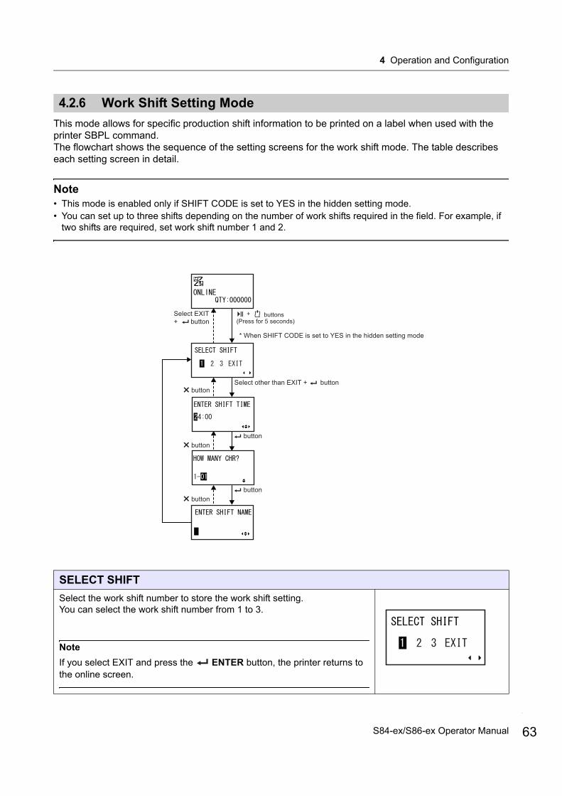
4 Operation and Configuration
4.2.6 Work Shift Setting Mode
This mode allows for specific production shift information to be printed on a label when used with the printer SBPL command.The flowchart shows the sequence of the setting screens for the work shift mode. The table describes each setting screen in detail.
Note• This mode is enabled only if SHIFT CODE is set to YES in the hidden setting mode.• You can set up to three shifts depending on the number of work shifts required in the field. For example, if
two shifts are required, set work shift number 1 and 2.
SELECT SHIFT
Select the work shift number to store the work shift setting.You can select the work shift number from 1 to 3.
Note
If you select EXIT and press the ENTER button, the printer returns to the online screen.
(Press for 5 seconds)buttons+
* When SHIFT CODE is set to YES in the hidden setting mode
Select EXIT + button
Select other than EXIT + buttonbutton
buttonbutton
buttonbutton
63S84-ex/S86-ex Operator Manual

4 Operation and Configuration
64
ENTER SHIFT TIME
Set the printer start time in 24-hour format.
Press the / buttons to shift the cursor and press the / buttons to change the value.
Press the ENTER button to save the value and proceed to the next setting screen.
HOW MANY CHR?
Set the character size of the SHIFT NAME by specifying the number of characters.
Select the number of characters using the / buttons and then press
the ENTER button.
The setting range is from 01 to 16.
ENTER SHIFT NAME
Specify a name for the work shift.Available characters are A to Z, space and 0 to 9.The number of characters you can enter depends on the character size set in the HOW MANY CHR? screen.
Press the / buttons to shift the cursor and press the / buttons to set the character.
Press the ENTER button to save the work shift name.
S84-ex/S86-ex Operator Manual
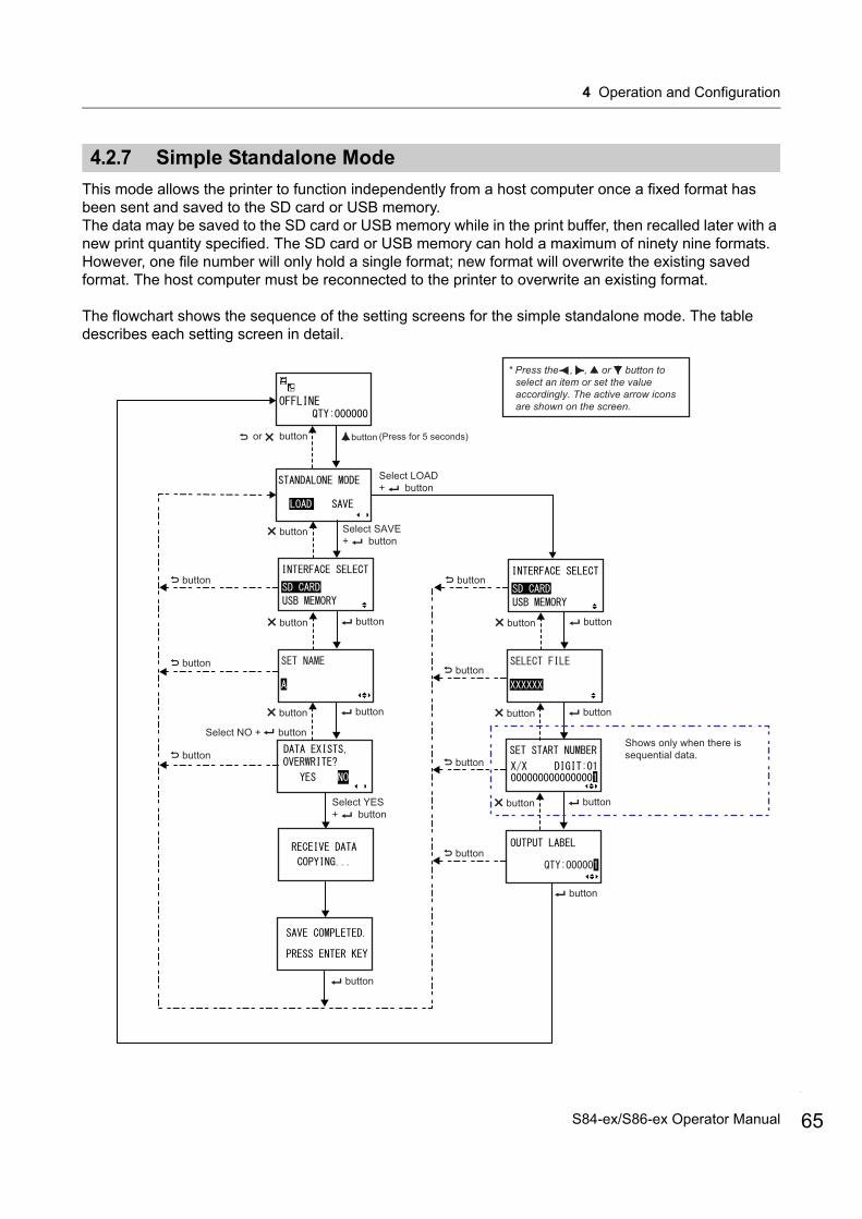
4 Operation and Configuration
4.2.7 Simple Standalone Mode
This mode allows the printer to function independently from a host computer once a fixed format has been sent and saved to the SD card or USB memory.The data may be saved to the SD card or USB memory while in the print buffer, then recalled later with a new print quantity specified. The SD card or USB memory can hold a maximum of ninety nine formats. However, one file number will only hold a single format; new format will overwrite the existing saved format. The host computer must be reconnected to the printer to overwrite an existing format.
The flowchart shows the sequence of the setting screens for the simple standalone mode. The table describes each setting screen in detail.
* Press the , , or button to select an item or set the value accordingly. The active arrow icons are shown on the screen.
or button
buttonbutton
button
button
Select LOAD + button
Select SAVE + button
button
button
buttonbutton
button (Press for 5 seconds)
Select YES + button
button
buttonbutton
buttonbutton
buttonbutton
button
button
button
button
Shows only when there issequential data.
Select NO + button
button
65S84-ex/S86-ex Operator Manual
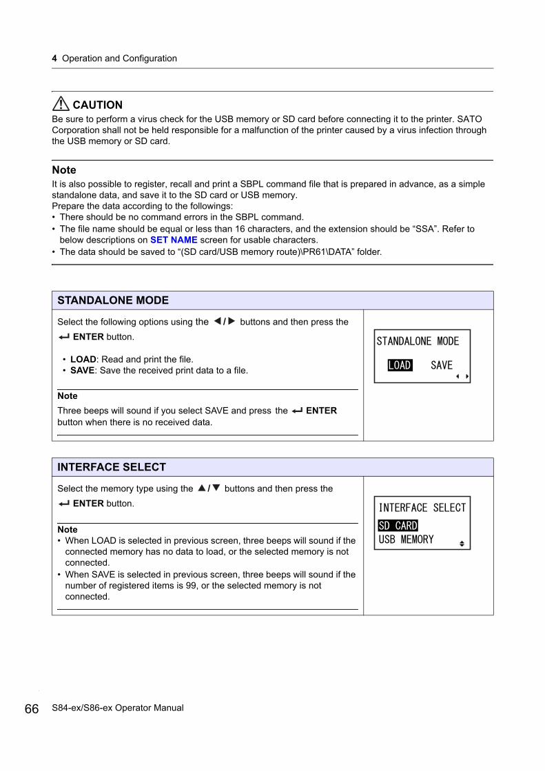
4 Operation and Configuration
66
CAUTIONBe sure to perform a virus check for the USB memory or SD card before connecting it to the printer. SATO Corporation shall not be held responsible for a malfunction of the printer caused by a virus infection through the USB memory or SD card.
NoteIt is also possible to register, recall and print a SBPL command file that is prepared in advance, as a simple standalone data, and save it to the SD card or USB memory.Prepare the data according to the followings:• There should be no command errors in the SBPL command.• The file name should be equal or less than 16 characters, and the extension should be “SSA”. Refer to
below descriptions on SET NAME screen for usable characters.• The data should be saved to “(SD card/USB memory route)\PR61\DATA” folder.
STANDALONE MODE
Select the following options using the / buttons and then press the
ENTER button.
• LOAD: Read and print the file.• SAVE: Save the received print data to a file.
Note
Three beeps will sound if you select SAVE and press the ENTER button when there is no received data.
INTERFACE SELECT
Select the memory type using the / buttons and then press the
ENTER button.
Note• When LOAD is selected in previous screen, three beeps will sound if the
connected memory has no data to load, or the selected memory is not connected.
• When SAVE is selected in previous screen, three beeps will sound if the number of registered items is 99, or the selected memory is not connected.
S84-ex/S86-ex Operator Manual
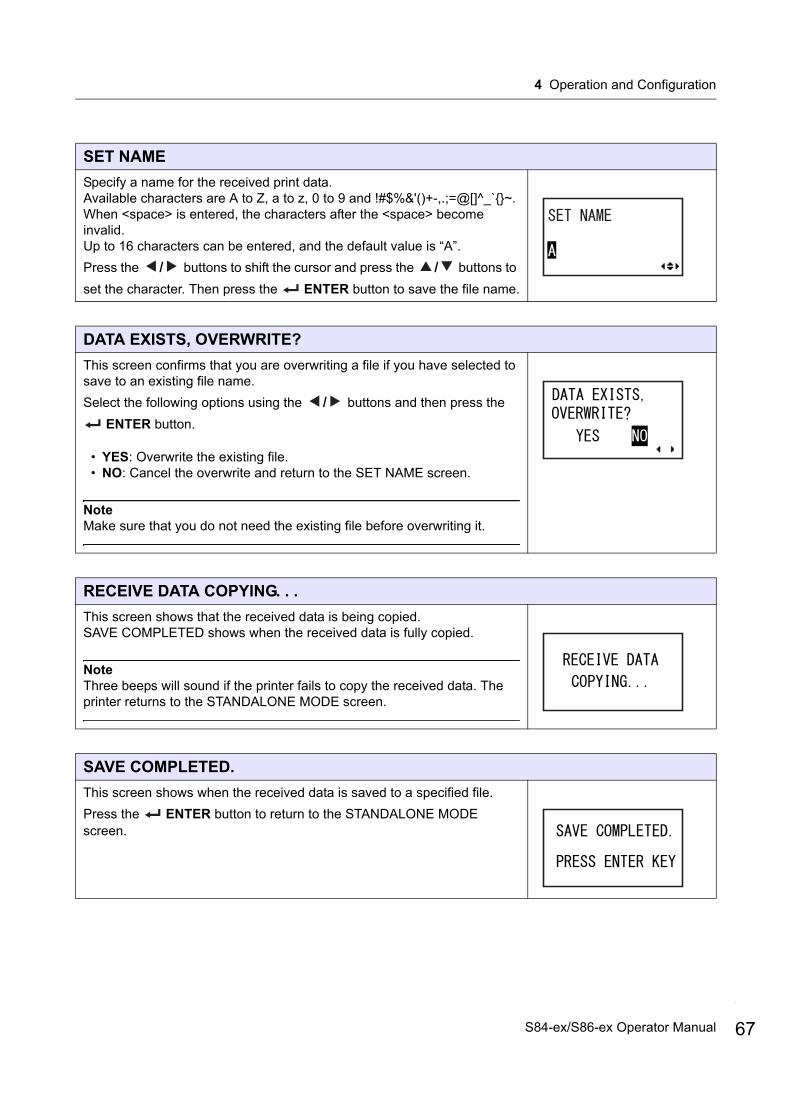
4 Operation and Configuration
SET NAME
Specify a name for the received print data.Available characters are A to Z, a to z, 0 to 9 and !#$%&'()+-,.;=@[]^_`{}~.When <space> is entered, the characters after the <space> become invalid.Up to 16 characters can be entered, and the default value is “A”.
Press the / buttons to shift the cursor and press the / buttons to
set the character. Then press the ENTER button to save the file name.
DATA EXISTS, OVERWRITE?
This screen confirms that you are overwriting a file if you have selected to save to an existing file name.
Select the following options using the / buttons and then press the
ENTER button.
• YES: Overwrite the existing file.• NO: Cancel the overwrite and return to the SET NAME screen.
NoteMake sure that you do not need the existing file before overwriting it.
RECEIVE DATA COPYING. . .
This screen shows that the received data is being copied.SAVE COMPLETED shows when the received data is fully copied.
NoteThree beeps will sound if the printer fails to copy the received data. The printer returns to the STANDALONE MODE screen.
SAVE COMPLETED.
This screen shows when the received data is saved to a specified file.
Press the ENTER button to return to the STANDALONE MODE screen.
67S84-ex/S86-ex Operator Manual
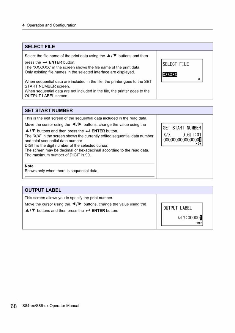
4 Operation and Configuration
68
SELECT FILE
Select the file name of the print data using the / buttons and then
press the ENTER button.The “XXXXXX” in the screen shows the file name of the print data.Only existing file names in the selected interface are displayed.
When sequential data are included in the file, the printer goes to the SET START NUMBER screen.When sequential data are not included in the file, the printer goes to the OUTPUT LABEL screen.
SET START NUMBER
This is the edit screen of the sequential data included in the read data.
Move the cursor using the / buttons, change the value using the
/ buttons and then press the ENTER button.The “X/X” in the screen shows the currently edited sequential data number and total sequential data number.DIGIT is the digit number of the selected cursor.The screen may be decimal or hexadecimal according to the read data.The maximum number of DIGIT is 99.
NoteShows only when there is sequential data.
OUTPUT LABEL
This screen allows you to specify the print number.
Move the cursor using the / buttons, change the value using the
/ buttons and then press the ENTER button.
S84-ex/S86-ex Operator Manual
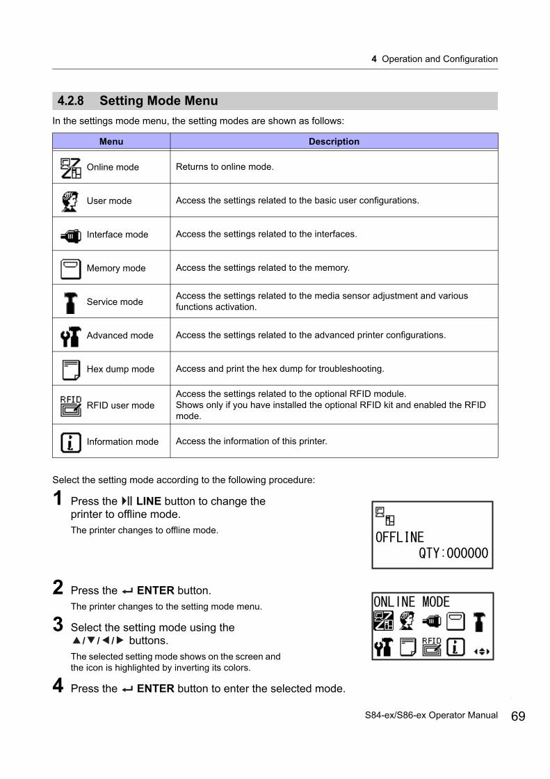
4 Operation and Configuration
4.2.8 Setting Mode Menu
In the settings mode menu, the setting modes are shown as follows:
Select the setting mode according to the following procedure:
1 Press the LINE button to change the printer to offline mode. The printer changes to offline mode.
2 Press the ENTER button.The printer changes to the setting mode menu.
3 Select the setting mode using the / / / buttons.
The selected setting mode shows on the screen and the icon is highlighted by inverting its colors.
4 Press the ENTER button to enter the selected mode.
Menu Description
Online mode Returns to online mode.
User mode Access the settings related to the basic user configurations.
Interface mode Access the settings related to the interfaces.
Memory mode Access the settings related to the memory.
Service modeAccess the settings related to the media sensor adjustment and various functions activation.
Advanced mode Access the settings related to the advanced printer configurations.
Hex dump mode Access and print the hex dump for troubleshooting.
RFID user modeAccess the settings related to the optional RFID module. Shows only if you have installed the optional RFID kit and enabled the RFID mode.
Information mode Access the information of this printer.
69S84-ex/S86-ex Operator Manual

4 Operation and Configuration
70
The functions of the buttons in the setting mode menu are shown as below.
Enters the selected setting mode.
Navigate to select the setting mode.
Enters offline mode.
Enters offline mode.
Selected icon highlighted with inverted colors.
Valid arrow buttons for selection.
Selectedsettingmode.
S84-ex/S86-ex Operator Manual

4 Operation and Configuration
4.2.9 User Mode
The flowchart shows the sequence of the setting screens for the user mode. The table describes each setting screen in detail.
Shows only when the PASSWORD input is enabled
* Press the , , or button to select an item or set the value accordingly. The active arrow icons are shown on the screen.
button
button
button
button
button
button
button
buttonbutton
button
buttonbutton
buttonbutton
buttonbutton
buttonbutton
buttonbutton
buttonbutton
buttonbutton
Shows only when GB18030 is selected
button
Proceed to .U-A
71S84-ex/S86-ex Operator Manual

4 Operation and Configuration
72
OFFSET VOLUME
The setting values of the adjustment mode are shown.
• PITCH: Shows the print position offset value. • OFFSET: Shows the stop position offset value. • DARKNESS: Shows the darkness setting value.
You can change these values in Adjustment Mode and Test Print Mode.
* Press the , , or button to select an item or set the value accordingly. The active arrow icons are shown on the screen.
button
button
button
buttonbutton
buttonbutton
Select NO + button
button
Select ENABLE + buttonbutton
buttonbutton
Select DISABLE + button
button
Select YES + button
button
button
Select NO + buttonSelect YES + button
U-A
S84-ex/S86-ex Operator Manual

4 Operation and Configuration
PRINT SPEED
The setting range varies depending on the model. • S84-ex (203 dpi): 4 to 16 ips (inches/sec)• S86-ex (203 dpi): 4 to 14 ips (inches/sec)• S84-ex (305 dpi): 4 to 14 ips (inches/sec)• S86-ex (305 dpi): 4 to 12 ips (inches/sec)• S84-ex (609 dpi): 2 to 6 ips (inches/sec)
NoteSetting the print speed to a level that is too fast may affect the print quality.
PRINT DARKNESS
Specify the print darkness from ten steps. The setting range is from 1 to 10. 1 is the lightest and 10 is the darkest.
PITCH OFFSET
This setting adjusts the pitch offset value.The media pitch is the distance between the leading edge (the edge that comes out of the printer first) of the media and the leading edge of the next media. Once the position has been set, it can be fine adjusted using the PITCH POSITION in adjustment mode.The setting range is from -49 mm (-1.9”) to +49 mm (+1.9”) and is adjustable by 1 mm (0.04”) steps.Set the offset value with '+' to move the print position opposite the feed direction and value with '-' to move the print position in the feed direction.
CHARACTER CODE
Set the character code to be used.
• UTF-8: Use UTF-8 for character encoding.• UTF-16: Use UTF-16 for character encoding.
73S84-ex/S86-ex Operator Manual

4 Operation and Configuration
74
2 BYTE FONTS
Set the kanji code to be used.
• GB18030: Set for use with simplified Chinese.• BIG5: Set for use with traditional Chinese.• KSX1001: Set for use with Korean.
The following kanji codes are available if GB18030 is selected:• MINCHO: Print the kanji code using MINCHO.• GOTHIC: Print the kanji code using GOTHIC.
NOTIFICATION FUNCTION SETTING
Select whether or not to set the notification function.
• YES: Set the notification function.• NO: Do not set the notification function. The screen returns to user
mode.
NoteFor details on the media motion when the set notification interval has reached, refer to Section 8.6 Notification Function.
NOTICE FUNCTION (SELECT)
Select the items for notification.
• CLEAN PRINTER: Notify when to perform cleaning of the printer.• CHANGE ROLLER: Notify when to perform replacement of the platen
roller.• CHANGE HEAD: Notify when to perform replacement of the print head.
NOTICE FUNCTION (ENABLE/DISABLE)
Enable or disable the notification for the item selected in the above NOTICE FUNCTION.
• ENABLE: Enable the notification function.• DISABLE: Disable the notification function.
S84-ex/S86-ex Operator Manual
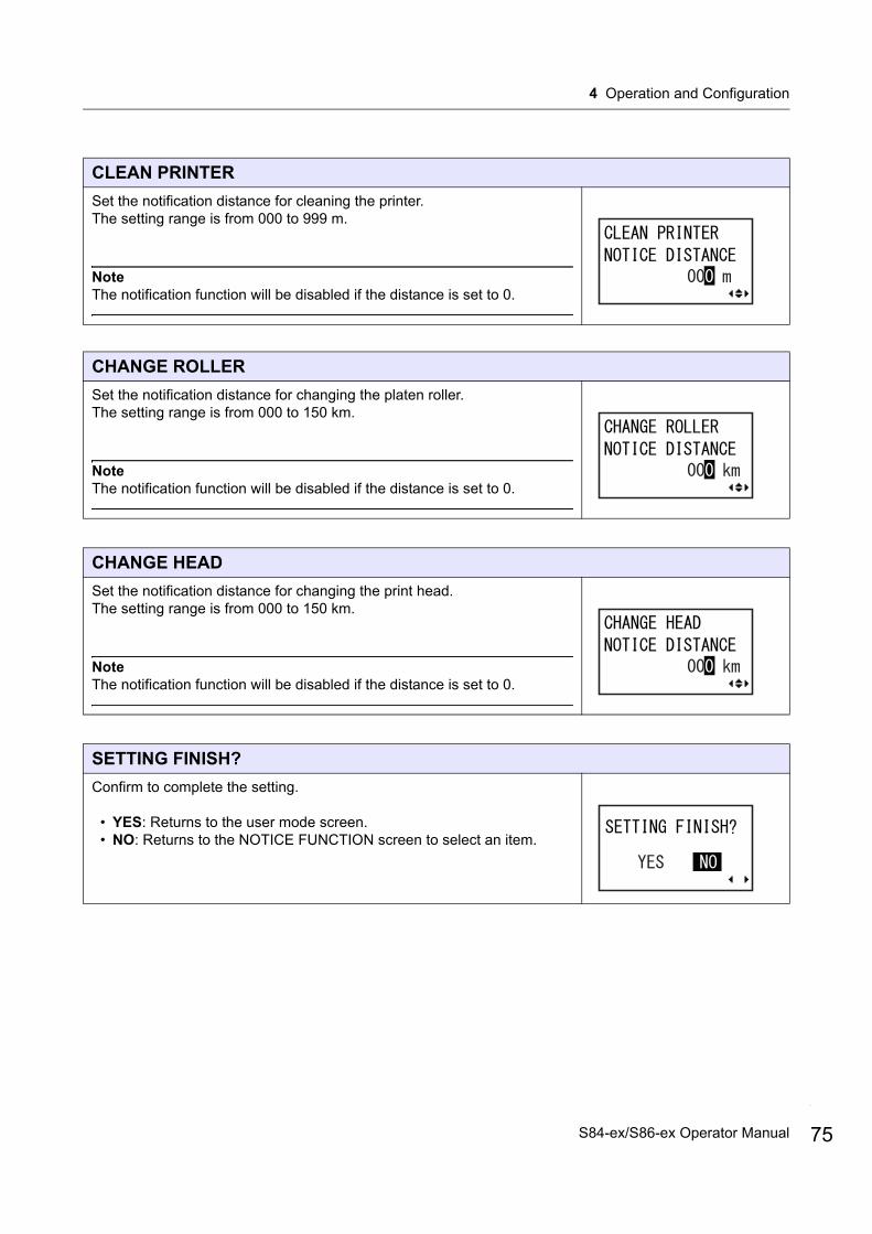
4 Operation and Configuration
CLEAN PRINTER
Set the notification distance for cleaning the printer. The setting range is from 000 to 999 m.
NoteThe notification function will be disabled if the distance is set to 0.
CHANGE ROLLER
Set the notification distance for changing the platen roller. The setting range is from 000 to 150 km.
NoteThe notification function will be disabled if the distance is set to 0.
CHANGE HEAD
Set the notification distance for changing the print head. The setting range is from 000 to 150 km.
NoteThe notification function will be disabled if the distance is set to 0.
SETTING FINISH?
Confirm to complete the setting.
• YES: Returns to the user mode screen.• NO: Returns to the NOTICE FUNCTION screen to select an item.
75S84-ex/S86-ex Operator Manual
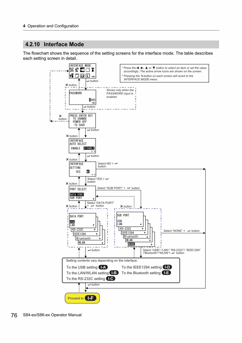
4 Operation and Configuration
76
4.2.10 Interface Mode
The flowchart shows the sequence of the setting screens for the interface mode. The table describes each setting screen in detail.
Setting contents vary depending on the interface.
Select NO + button
Shows only when the PASSWORD input is enabled
Select YES + button
Select “DATA PORT” + button
Select “USB”/ “LAN”/ “RS-232C”/ “IEEE1284” /“Bluetooth”/“WLAN”+ button
Select “NONE” + button
Proceed to .
button
buttonbutton
button
button
buttonbutton
button
button
button
button
button
Select “SUB PORT” + button
* Press the , , or button to select an item or set the value accordingly. The active arrow icons are shown on the screen.
* Pressing the button on each screen will revert to the INTERFACE MODE menu.
button
To the USB settingTo the LAN/WLAN settingTo the RS-232C setting
To the IEEE1284 settingTo the Bluetooth setting
I-F
I-A I-DI-B
I-CI-E
S84-ex/S86-ex Operator Manual
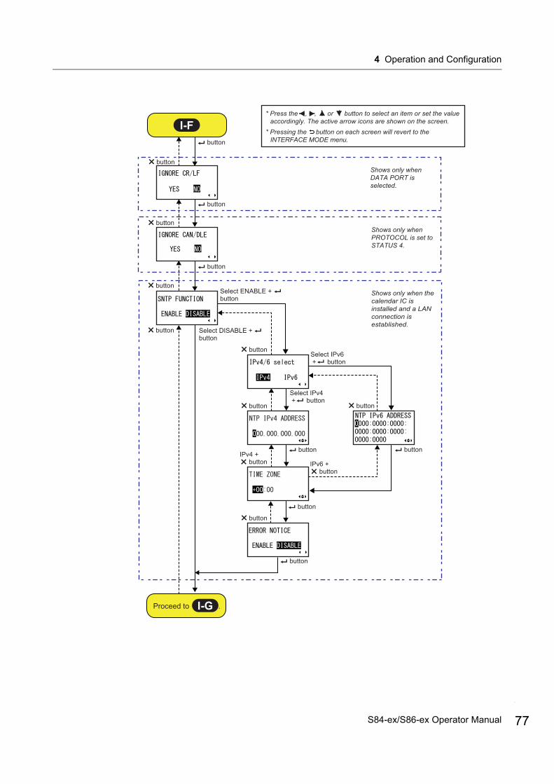
4 Operation and Configuration
button
button
button
button
button
button
button
Select ENABLE + button
Select DISABLE + button
Select IPv4 + button
Select IPv6 + button
button
button
button
button
* Press the , , or button to select an item or set the value accordingly. The active arrow icons are shown on the screen.
* Pressing the button on each screen will revert to the INTERFACE MODE menu.
button
button
I-F
Proceed to .I-G
button
buttonIPv4 + button IPv6 +
button
Shows only when PROTOCOL is set to STATUS 4.
Shows only when the calendar IC is installed and a LAN connection is established.
Shows only when DATA PORT is selected.
77S84-ex/S86-ex Operator Manual
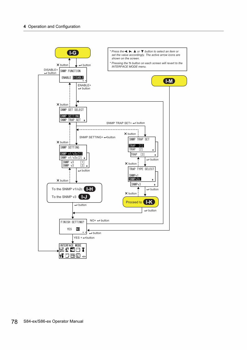
4 Operation and Configuration
78
* Press the , , or button to select an item or set the value accordingly. The active arrow icons are shown on the screen.
* Pressing the button on each screen will revert to the INTERFACE MODE menu.
SNMP SETTING+ button
SNMP TRAP SET+
button
ENABLE+ button
button
button
button
button
button
button
button
button
button
button
buttonbutton
I-G
I-M
Proceed to .I-K
I-HTo the SNMP v1/v2c
I-JTo the SNMP v3
button
button
NO+ button
YES + button
DISABLE+ button
S84-ex/S86-ex Operator Manual
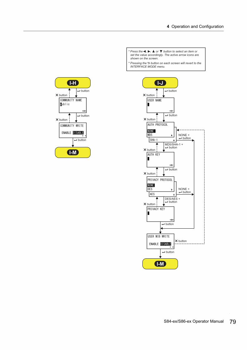
4 Operation and Configuration
button
button
button
button
button
buttonbutton
button
button
button
buttonbutton
button
button
button
I-H
button button
I-J
I-M
I-M
NONE +
buttonNONE +
* Press the , , or button to select an item or set the value accordingly. The active arrow icons are shown on the screen.
* Pressing the button on each screen will revert to the INTERFACE MODE menu.
buttonMD5/SHA-1 +
buttonDES/AES +
79S84-ex/S86-ex Operator Manual
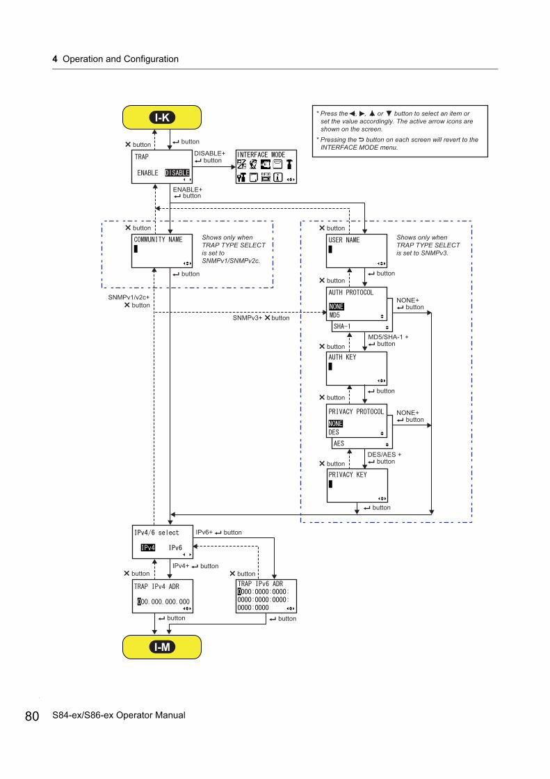
4 Operation and Configuration
80
Shows only when TRAP TYPE SELECT is set to SNMPv1/SNMPv2c.
IPv4+
button button
button
button button button
button button
button
SNMPv1/v2c+button
SNMPv3+ button
button
I-K
I-M
buttonbutton
buttonbutton
button
button button
button
button
buttonNONE+
buttonNONE+
* Press the , , or button to select an item or set the value accordingly. The active arrow icons are shown on the screen.
* Pressing the button on each screen will revert to the INTERFACE MODE menu.
IPv6+ button
DISABLE+ button
ENABLE+ button
Shows only when TRAP TYPE SELECT is set to SNMPv3.
MD5/SHA-1 +
DES/AES +
S84-ex/S86-ex Operator Manual

4 Operation and Configuration
PRESS ENTER KEY
This screen reminds the user to press the ENTER button to change or power off the printer to save the setting.
INTERFACE AUTO SELECT
Enable or disable the interface auto detection.
• ENABLE: Automatically select the connected interface.• DISABLE: The interface is selected based on the interface setting.
NoteThe setting will be effective only if you power on the printer again.
INTERFACE SETTING
Set whether or not to perform the interface settings.
• YES: Enter the PORT SELECT screen.• NO: Enter the IGNORE CR/LF screen.
PORT SELECT
Select the port used for the connected interface.
• DATA PORT: For receiving various SBPL commands and executing print operations.
• SUB PORT: For monitoring the printer status and connecting to external devices.
81S84-ex/S86-ex Operator Manual
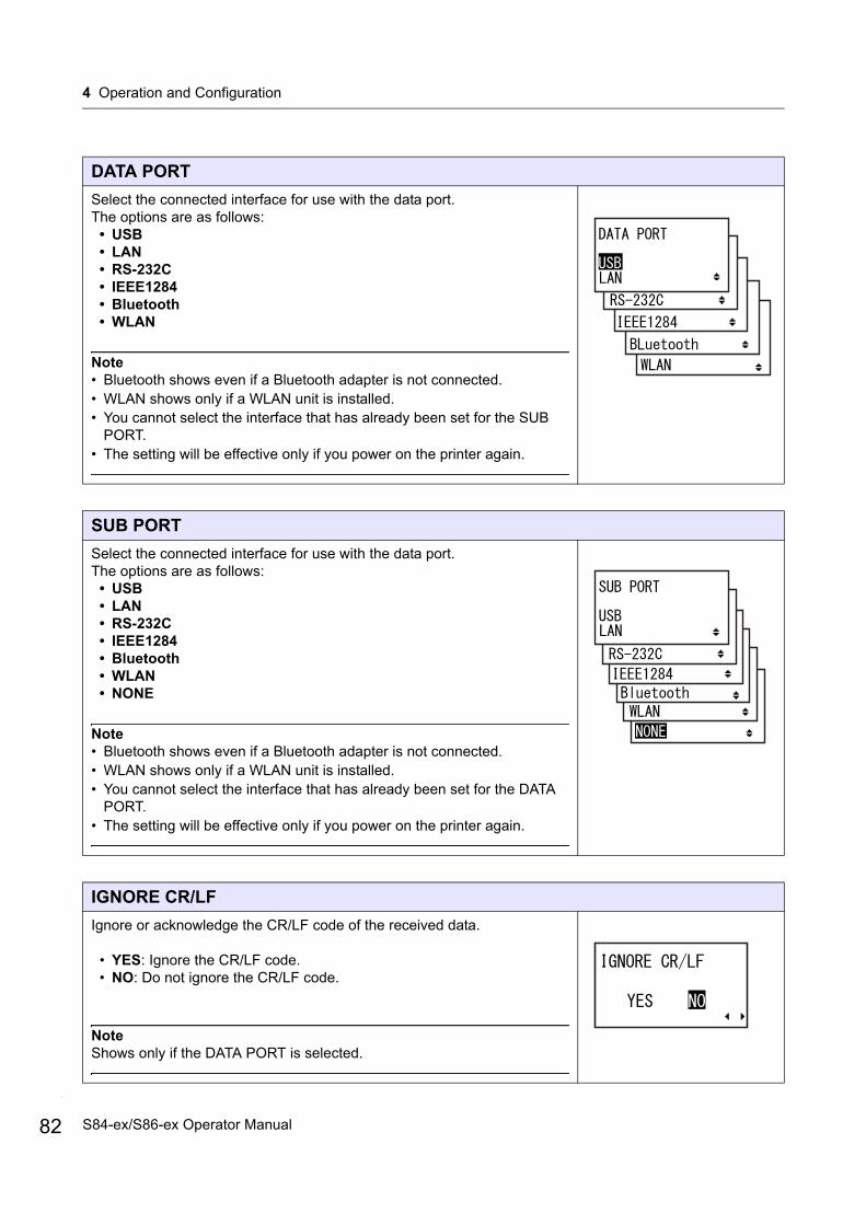
4 Operation and Configuration
82
DATA PORT
Select the connected interface for use with the data port.The options are as follows:
• USB• LAN• RS-232C• IEEE1284• Bluetooth• WLAN
Note• Bluetooth shows even if a Bluetooth adapter is not connected.• WLAN shows only if a WLAN unit is installed.• You cannot select the interface that has already been set for the SUB
PORT.• The setting will be effective only if you power on the printer again.
SUB PORT
Select the connected interface for use with the data port.The options are as follows:
• USB• LAN• RS-232C• IEEE1284• Bluetooth• WLAN • NONE
Note• Bluetooth shows even if a Bluetooth adapter is not connected.• WLAN shows only if a WLAN unit is installed.• You cannot select the interface that has already been set for the DATA
PORT.• The setting will be effective only if you power on the printer again.
IGNORE CR/LF
Ignore or acknowledge the CR/LF code of the received data.
• YES: Ignore the CR/LF code.• NO: Do not ignore the CR/LF code.
NoteShows only if the DATA PORT is selected.
S84-ex/S86-ex Operator Manual

4 Operation and Configuration
IGNORE CAN/DLE
Ignore or acknowledge the CAN/DLE code of the received data.
• YES: Ignore the CAN/DLE code.• NO: Do not ignore the CAN/DLE code.
NoteShows only if PROTOCOL is set to STATUS4.
SNTP FUNCTION
Enable or disable the SNTP function.
• ENABLE: Perform the time correction of the calendar IC.• DISABLE: Do not perform the time correction of the calendar IC.
NoteShows only if the calendar IC is installed and the LAN interface is selected.
IPv4/6 select
Select IP address type of SNTP.
• IPv4• IPv6
NoteShows only if the SNTP function is enabled.
NTP IPv4 ADDRESS
Set the IPv4 address for NTP server.
The setting range is from 0.0.0.0 to 255.255.255.255.
NoteShows only if the SNTP function is enabled.
83S84-ex/S86-ex Operator Manual

4 Operation and Configuration
84
NTP IPv6 ADDRESS
Set the IPv6 address for NTP server.
The setting range is from 0000:0000:0000:0000:0000:0000:0000:0000 to FFFF:FFFF:FFFF:FFFF:FFFF:FFFF:FFFF:FFFF.
NoteShows only if the SNTP function is enabled.
TIME ZONE
Set the time zone.The setting range is from -12:45 to +14:45.
NoteShows only if the SNTP function is enabled.
ERROR NOTICE
Set whether or not to notify the SNTP function error.
• ENABLE: Shows an error notice when failing to correct the time.• DISABLE: Does not show an error notice when failing to correct the
time.
NoteShows only if the SNTP function is enabled.
SNMP FUNCTION
Set the SNMP function.
• ENABLE: Enables the SNMP function and goes to “SNMP setting select” screen.
• DISABLE: Disables the SNMP function and goes to “Interface select screen.
NoteShows only if the LAN interface is selected.
S84-ex/S86-ex Operator Manual
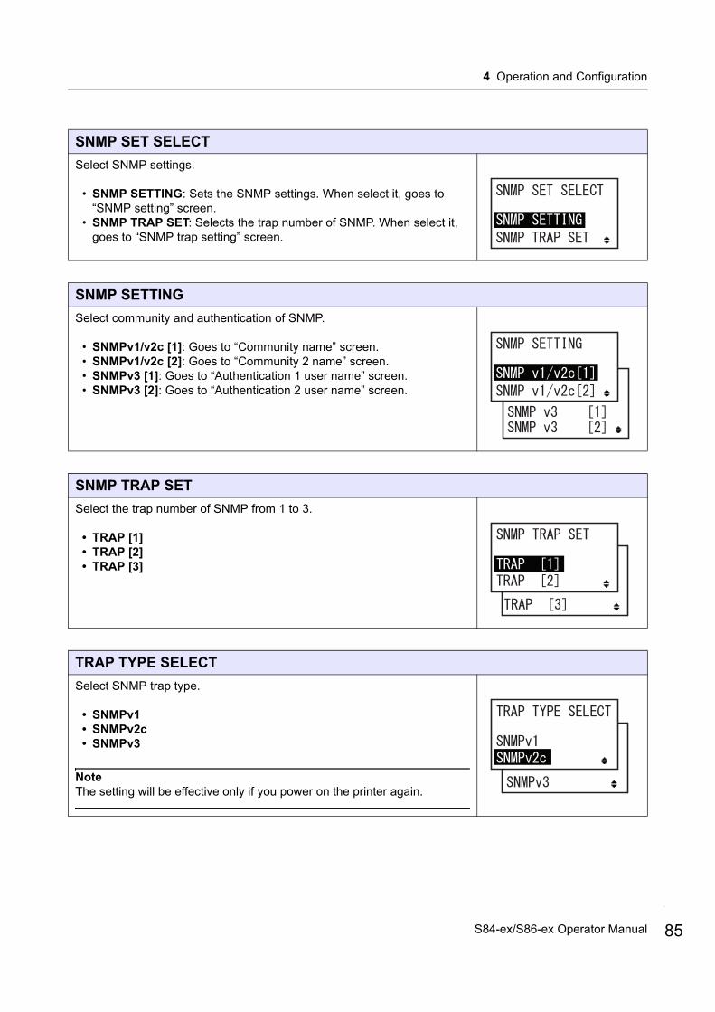
4 Operation and Configuration
SNMP SET SELECT
Select SNMP settings.
• SNMP SETTING: Sets the SNMP settings. When select it, goes to “SNMP setting” screen.
• SNMP TRAP SET: Selects the trap number of SNMP. When select it, goes to “SNMP trap setting” screen.
SNMP SETTING
Select community and authentication of SNMP.
• SNMPv1/v2c [1]: Goes to “Community name” screen.• SNMPv1/v2c [2]: Goes to “Community 2 name” screen.• SNMPv3 [1]: Goes to “Authentication 1 user name” screen.• SNMPv3 [2]: Goes to “Authentication 2 user name” screen.
SNMP TRAP SET
Select the trap number of SNMP from 1 to 3.
• TRAP [1]• TRAP [2]• TRAP [3]
TRAP TYPE SELECT
Select SNMP trap type.
• SNMPv1• SNMPv2c• SNMPv3
NoteThe setting will be effective only if you power on the printer again.
85S84-ex/S86-ex Operator Manual

4 Operation and Configuration
86
COMMUNITY NAME
Input SNMP community name.
• When SNMPv1/v2c [1] is selected the default is “public”.• When SNMPv1/v2c [2] is selected the default is “ ” (none).
Note• Up to 32 alphanumeric characters and symbols (from 20H to 7EH) can
be set. • Specify “ ” to input a space.• The setting will be effective only if you power on the printer again.
COMMUNITY WRITE
Enable or disable writing to MIB when accessing to community.
• ENABLE: Allows writing to MIB.• DISABLE: Does not allow writing to MIB.
NoteWriting possible OID are sysContact, sysName, and sysLocation.
USER NAME
Input SNMP authentication user name.
Press the / buttons to shift the cursor and press the / buttons to change the value.
Press the ENTER button to save the value and proceed to the next setting screen.
Note• Up to 32 alphanumeric characters and symbols (from 20H to 7EH) can
be set.• Specify “ ” to input a space.• The setting will be effective only if you power on the printer again.
S84-ex/S86-ex Operator Manual
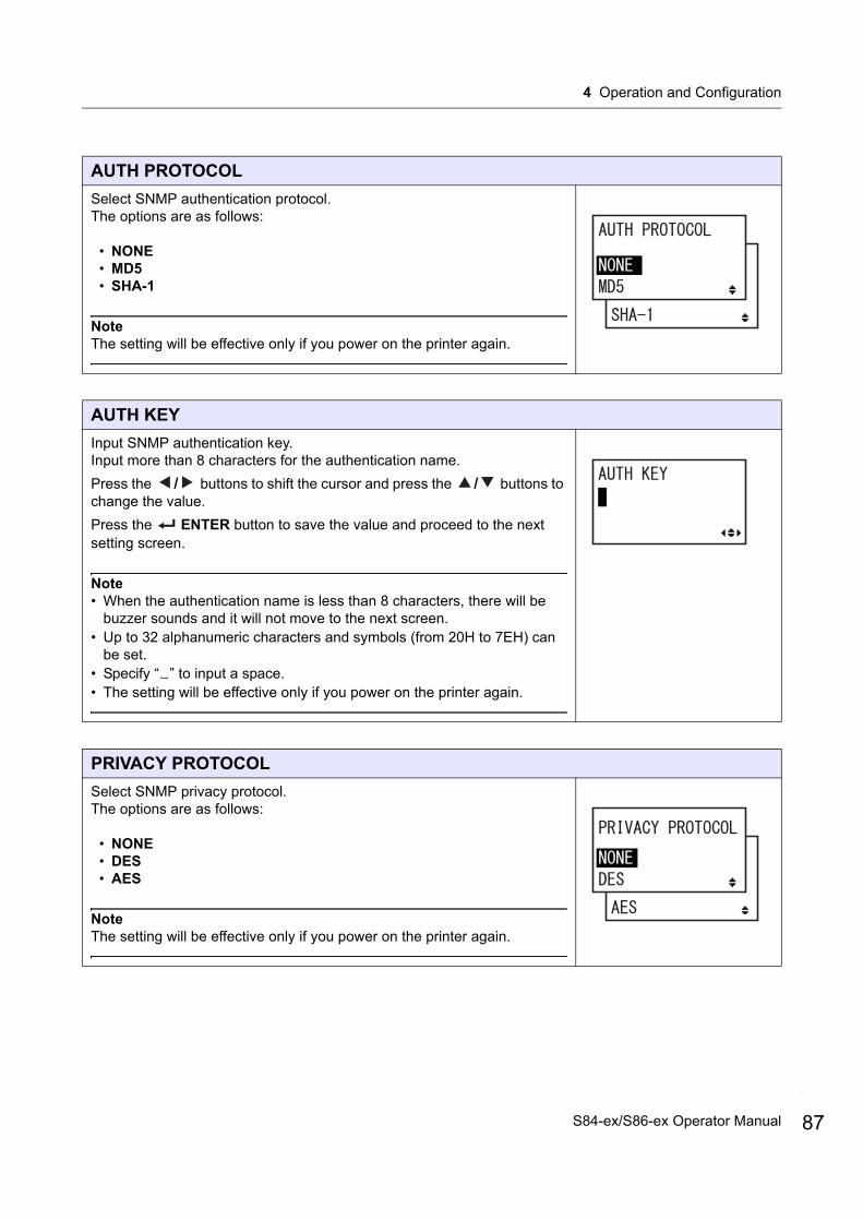
4 Operation and Configuration
AUTH PROTOCOL
Select SNMP authentication protocol.The options are as follows:
• NONE• MD5• SHA-1
NoteThe setting will be effective only if you power on the printer again.
AUTH KEY
Input SNMP authentication key.Input more than 8 characters for the authentication name.
Press the / buttons to shift the cursor and press the / buttons to change the value.
Press the ENTER button to save the value and proceed to the next setting screen.
Note• When the authentication name is less than 8 characters, there will be
buzzer sounds and it will not move to the next screen.• Up to 32 alphanumeric characters and symbols (from 20H to 7EH) can
be set.• Specify “ ” to input a space.• The setting will be effective only if you power on the printer again.
PRIVACY PROTOCOL
Select SNMP privacy protocol.The options are as follows:
• NONE• DES• AES
NoteThe setting will be effective only if you power on the printer again.
87S84-ex/S86-ex Operator Manual

4 Operation and Configuration
88
PRIVACY KEY
Input SNMP privacy key.Input more than 8 characters for the authentication name.
Press the / buttons to shift the cursor and press the / buttons to change the value.
Press the ENTER button to save the value and proceed to the next setting screen.
Note• When the authentication name is less than 8 characters, there will be
buzzer sounds and it will not move to the next screen.• Up to 32 alphanumeric characters and symbols (from 20H to 7EH) can
be set.• Specify “ ” to input a space.• The setting will be effective only if you power on the printer again.
USER MIB WRITE
Enable or disable writing to MIB at authentication access.
• ENABLE: Allows writing to MIB.• DISABLE: Does not allow writing to MIB.
NoteWriting possible OID are sysContact, sysName, and sysLocation.
TRAP
Set the SNMP trap.
• ENABLE: Allows the SNMP trap.• DISABLE: Does not allow the SNMP trap.
NoteThe setting will be effective only if you power on the printer again.
S84-ex/S86-ex Operator Manual
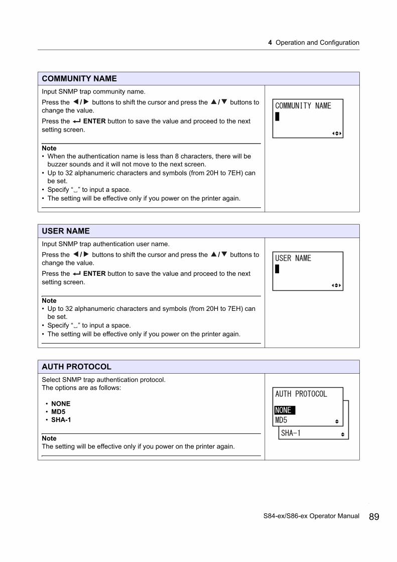
4 Operation and Configuration
COMMUNITY NAME
Input SNMP trap community name.
Press the / buttons to shift the cursor and press the / buttons to change the value.
Press the ENTER button to save the value and proceed to the next setting screen.
Note• When the authentication name is less than 8 characters, there will be
buzzer sounds and it will not move to the next screen.• Up to 32 alphanumeric characters and symbols (from 20H to 7EH) can
be set.• Specify “ ” to input a space.• The setting will be effective only if you power on the printer again.
USER NAME
Input SNMP trap authentication user name.
Press the / buttons to shift the cursor and press the / buttons to change the value.
Press the ENTER button to save the value and proceed to the next setting screen.
Note• Up to 32 alphanumeric characters and symbols (from 20H to 7EH) can
be set.• Specify “ ” to input a space.• The setting will be effective only if you power on the printer again.
AUTH PROTOCOL
Select SNMP trap authentication protocol.The options are as follows:
• NONE• MD5• SHA-1
NoteThe setting will be effective only if you power on the printer again.
89S84-ex/S86-ex Operator Manual
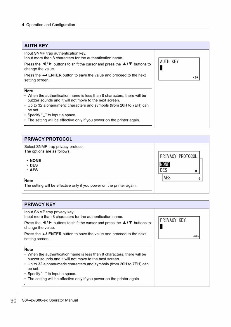
4 Operation and Configuration
90
AUTH KEY
Input SNMP trap authentication key. Input more than 8 characters for the authentication name.
Press the / buttons to shift the cursor and press the / buttons to change the value.
Press the ENTER button to save the value and proceed to the next setting screen.
Note• When the authentication name is less than 8 characters, there will be
buzzer sounds and it will not move to the next screen.• Up to 32 alphanumeric characters and symbols (from 20H to 7EH) can
be set.• Specify “ ” to input a space.• The setting will be effective only if you power on the printer again.
PRIVACY PROTOCOL
Select SNMP trap privacy protocol.The options are as follows:
• NONE• DES• AES
NoteThe setting will be effective only if you power on the printer again.
PRIVACY KEY
Input SNMP trap privacy key. Input more than 8 characters for the authentication name.
Press the / buttons to shift the cursor and press the / buttons to change the value.
Press the ENTER button to save the value and proceed to the next setting screen.
Note• When the authentication name is less than 8 characters, there will be
buzzer sounds and it will not move to the next screen.• Up to 32 alphanumeric characters and symbols (from 20H to 7EH) can
be set.• Specify “ ” to input a space.• The setting will be effective only if you power on the printer again.
S84-ex/S86-ex Operator Manual
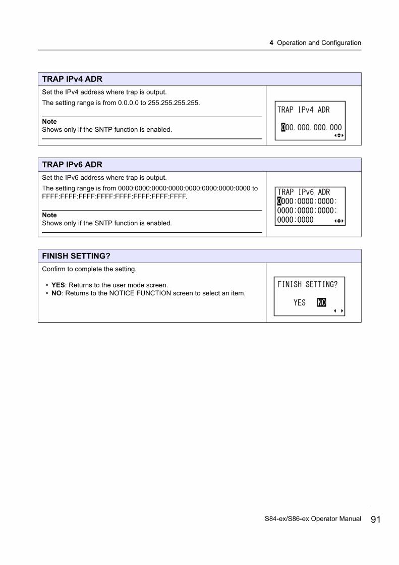
4 Operation and Configuration
TRAP IPv4 ADR
Set the IPv4 address where trap is output.
The setting range is from 0.0.0.0 to 255.255.255.255.
NoteShows only if the SNTP function is enabled.
TRAP IPv6 ADR
Set the IPv6 address where trap is output.
The setting range is from 0000:0000:0000:0000:0000:0000:0000:0000 to FFFF:FFFF:FFFF:FFFF:FFFF:FFFF:FFFF:FFFF.
NoteShows only if the SNTP function is enabled.
FINISH SETTING?
Confirm to complete the setting.
• YES: Returns to the user mode screen.• NO: Returns to the NOTICE FUNCTION screen to select an item.
91S84-ex/S86-ex Operator Manual

4 Operation and Configuration
92
USB Setting
PROTOCOL
Set the communication protocol.
• STATUS4: When selected, the printer will proceed to the IGNORE CR/LF screen.
• STATUS5: When selected, the printer will proceed to the ITEM NO. CHECK screen.
ITEM NO. CHECK
Set the item number check function.
• ENABLE: Enable the item number check function.• DISABLE: Disable the item number check function.
NoteShows only if PROTOCOL is set to STATUS5.
Shows only when STATUS5 is selected.
* Press the , , or button to select an item or set the value accordingly. The active arrow icons are shown on the screen.
* Pressing the button on each screen will revert to the INTERFACE MODE menu.
button
button
button
buttonbutton
button
I-A
Proceed to .I-F
S84-ex/S86-ex Operator Manual
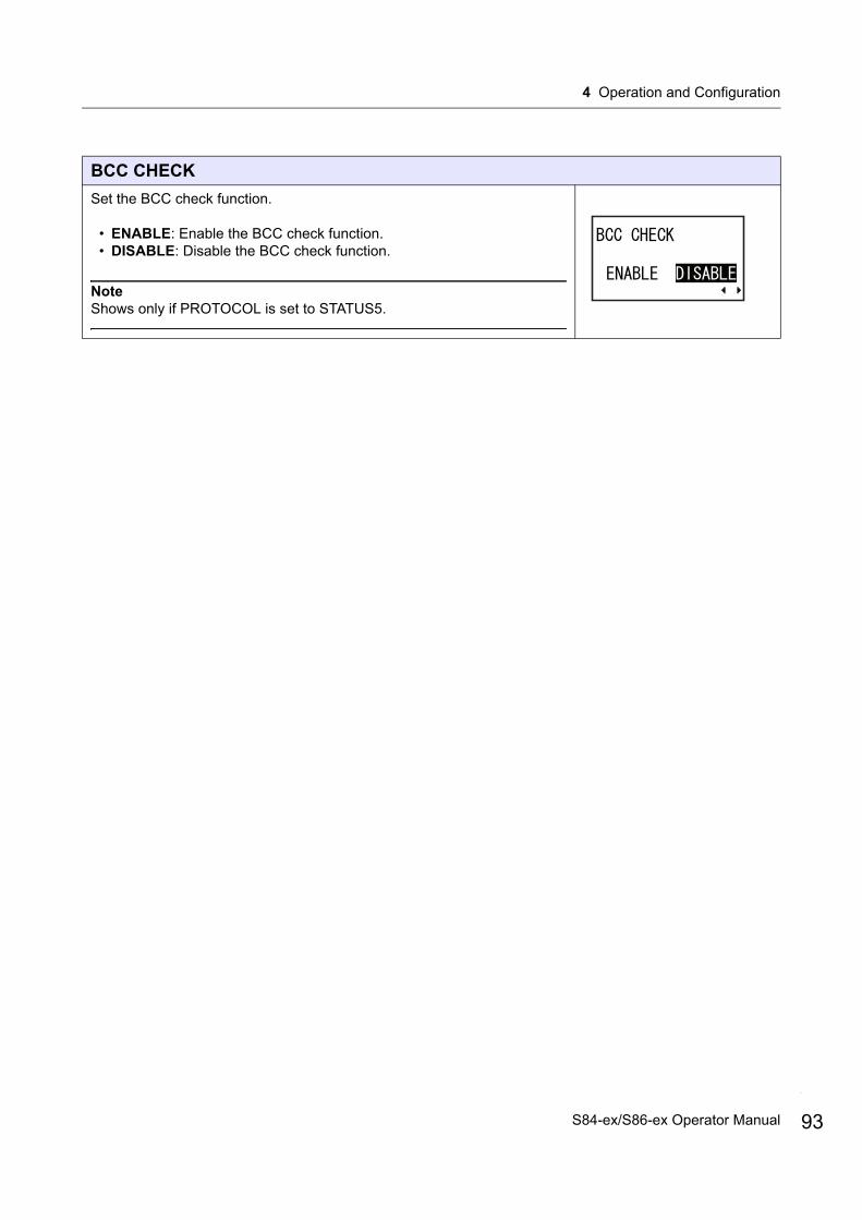
4 Operation and Configuration
BCC CHECK
Set the BCC check function.
• ENABLE: Enable the BCC check function.• DISABLE: Disable the BCC check function.
NoteShows only if PROTOCOL is set to STATUS5.
93S84-ex/S86-ex Operator Manual
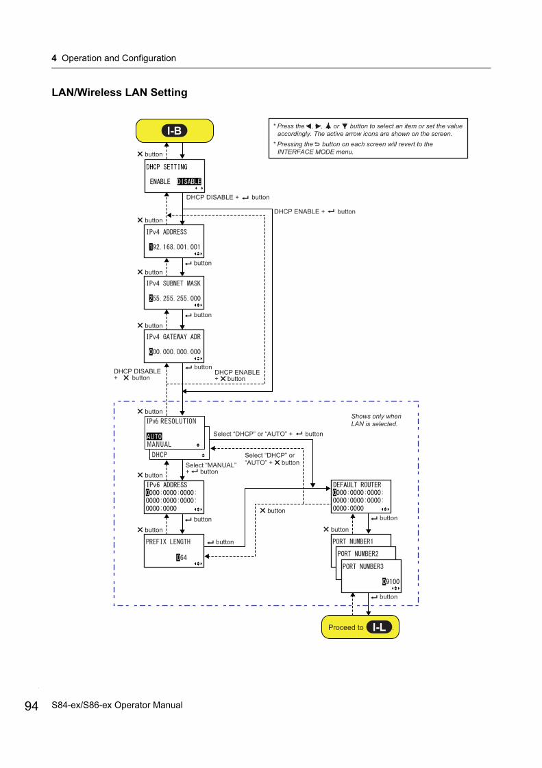
4 Operation and Configuration
94
LAN/Wireless LAN Setting
* Press the , , or button to select an item or set the value accordingly. The active arrow icons are shown on the screen.
* Pressing the button on each screen will revert to the INTERFACE MODE menu.
DHCP DISABLE + button
DHCP ENABLE + button
Select “DHCP” or “AUTO” + button
DHCP ENABLE + button
Select “DHCP” or “AUTO” + button
DHCP DISABLE + button
buttonbutton
button
button
button
button
button
button
button
button
button
button
button
button
Shows only when LAN is selected.
button
button
I-B
Proceed to .I-L
Select “MANUAL” + button
S84-ex/S86-ex Operator Manual
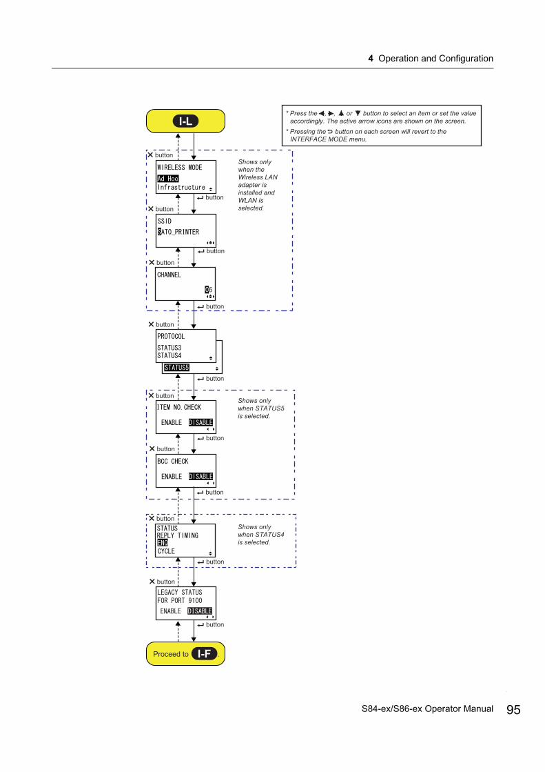
4 Operation and Configuration
Shows only when STATUS5 is selected.
Shows only when STATUS4 is selected.
Shows only when the Wireless LAN adapter is installed and WLAN is selected.
* Press the , , or button to select an item or set the value accordingly. The active arrow icons are shown on the screen.
* Pressing the button on each screen will revert to the INTERFACE MODE menu.
button
button
button
button
button
button
button
button
button
button
button
button
button
button
I-L
Proceed to .I-F
button
button
95S84-ex/S86-ex Operator Manual
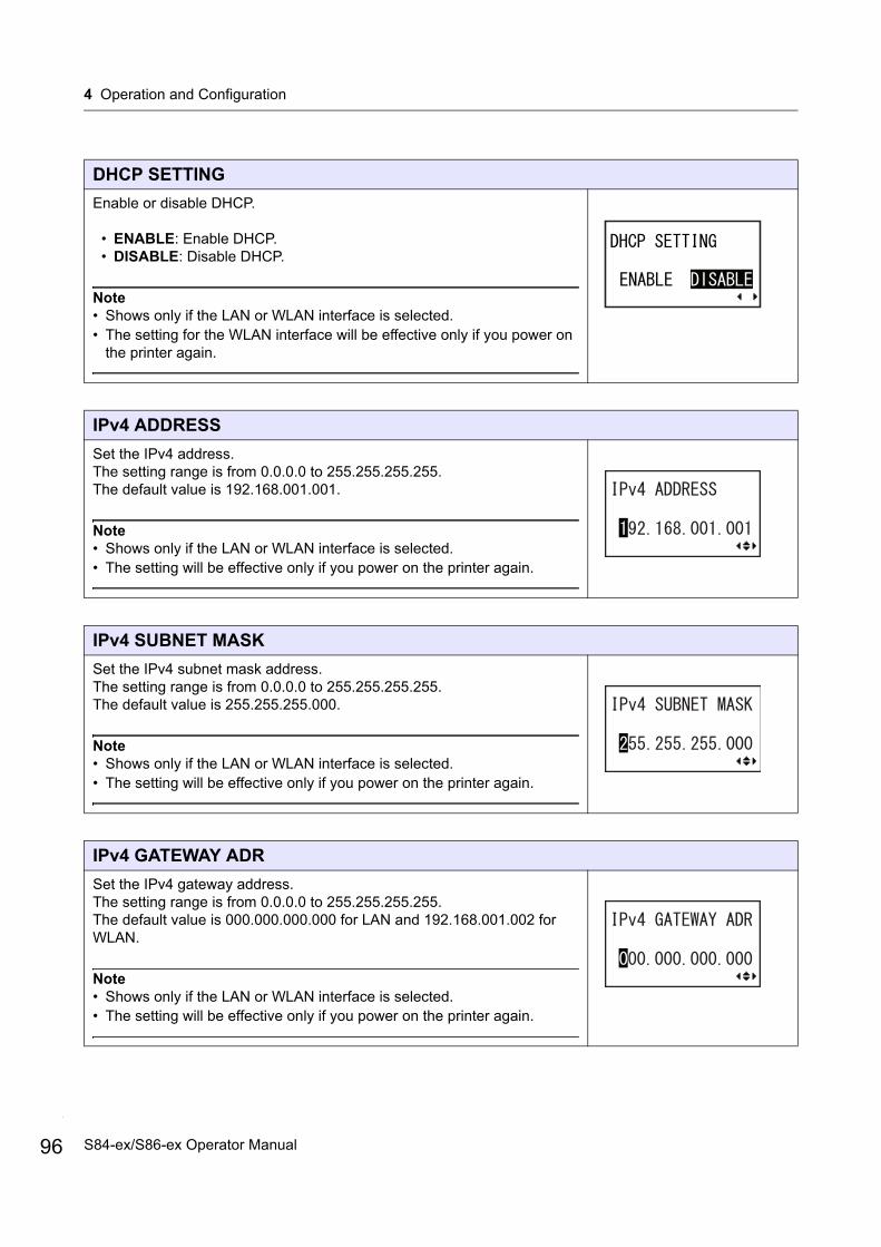
4 Operation and Configuration
96
DHCP SETTING
Enable or disable DHCP.
• ENABLE: Enable DHCP.• DISABLE: Disable DHCP.
Note• Shows only if the LAN or WLAN interface is selected.• The setting for the WLAN interface will be effective only if you power on
the printer again.
IPv4 ADDRESS
Set the IPv4 address.The setting range is from 0.0.0.0 to 255.255.255.255.The default value is 192.168.001.001.
Note• Shows only if the LAN or WLAN interface is selected.• The setting will be effective only if you power on the printer again.
IPv4 SUBNET MASK
Set the IPv4 subnet mask address.The setting range is from 0.0.0.0 to 255.255.255.255.The default value is 255.255.255.000.
Note• Shows only if the LAN or WLAN interface is selected.• The setting will be effective only if you power on the printer again.
IPv4 GATEWAY ADR
Set the IPv4 gateway address.The setting range is from 0.0.0.0 to 255.255.255.255.The default value is 000.000.000.000 for LAN and 192.168.001.002 for WLAN.
Note• Shows only if the LAN or WLAN interface is selected.• The setting will be effective only if you power on the printer again.
S84-ex/S86-ex Operator Manual

4 Operation and Configuration
IPv6 RESOLUTION
Select IPv6 address setting method.The options are as follows:
• AUTO• MANUAL• DHCP
NoteShows only if the LAN interface is selected.
IPv6 ADDRESS
Set the IPv6 address.
NoteShows only if the LAN interface is selected and “MANUAL” is selected at “IPv6 RESOLUTION” screen.
PREFIX LENGTH
Set the prefix length.
NoteShows only if the LAN interface is selected and “MANUAL” is selected at “IPv6 RESOLUTION” screen.
DEFAULT ROUTER
Set the default router of IPv6.
NoteShows only if the LAN interface is selected and “MANUAL” is selected at “IPv6 RESOLUTION” screen.
97S84-ex/S86-ex Operator Manual
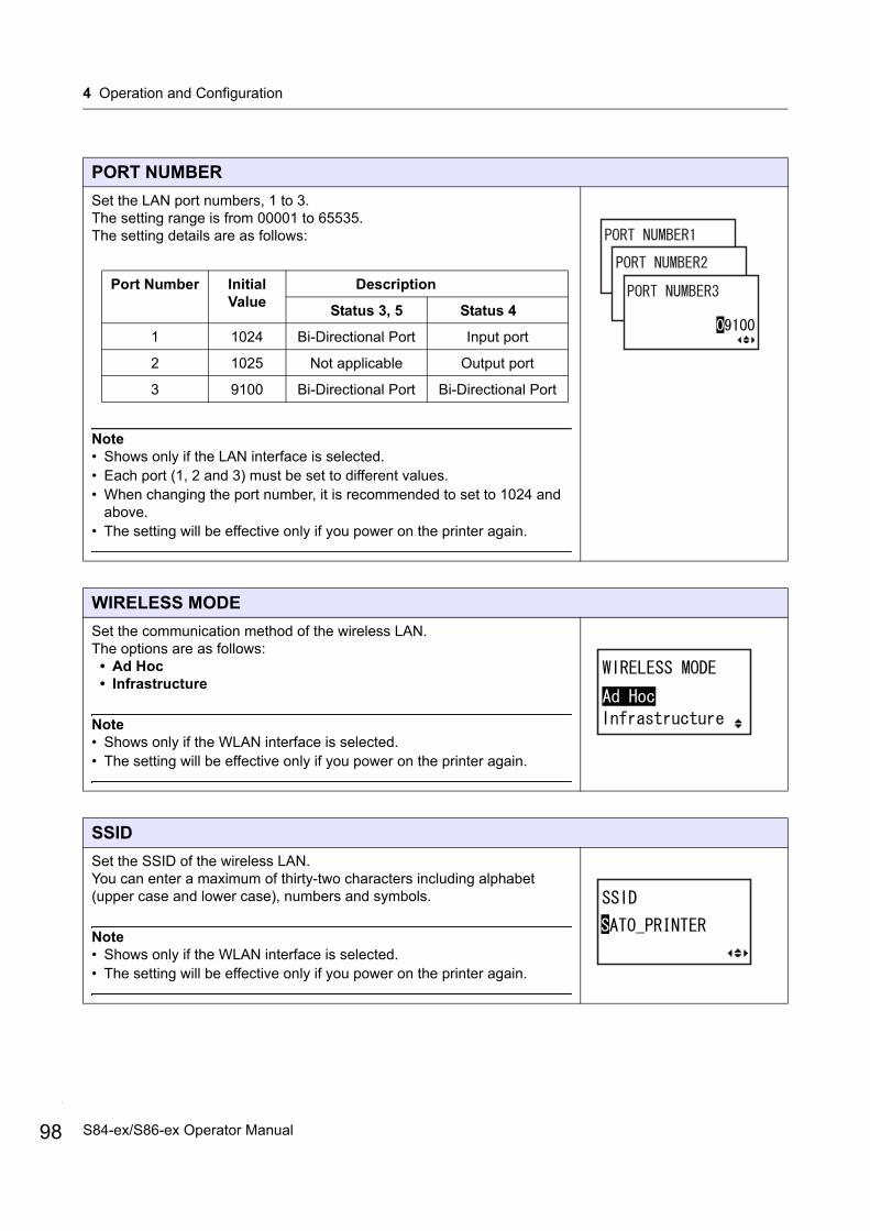
4 Operation and Configuration
98
PORT NUMBER
Set the LAN port numbers, 1 to 3. The setting range is from 00001 to 65535.The setting details are as follows:
Note• Shows only if the LAN interface is selected.• Each port (1, 2 and 3) must be set to different values.• When changing the port number, it is recommended to set to 1024 and
above.• The setting will be effective only if you power on the printer again.
WIRELESS MODE
Set the communication method of the wireless LAN.The options are as follows:
• Ad Hoc• Infrastructure
Note• Shows only if the WLAN interface is selected.• The setting will be effective only if you power on the printer again.
SSID
Set the SSID of the wireless LAN.You can enter a maximum of thirty-two characters including alphabet (upper case and lower case), numbers and symbols.
Note• Shows only if the WLAN interface is selected.• The setting will be effective only if you power on the printer again.
Port Number Initial Value
Description
Status 3, 5 Status 4
1 1024 Bi-Directional Port Input port
2 1025 Not applicable Output port
3 9100 Bi-Directional Port Bi-Directional Port
S84-ex/S86-ex Operator Manual

4 Operation and Configuration
CHANNEL
Set the communication channel of the wireless LAN.The setting range is from 01 to 13 and the default value is 06.
Note• Shows only if the WLAN interface is selected.• The setting will be effective only if you power on the printer again.• When the channel has become invalid due to a region code change, the
channel returns to its default setting.
PROTOCOL
Set the communication protocol.
• STATUS3: When selected, the printer will proceed to the IGNORE CR/LF screen.
• STATUS4: When selected, the printer will proceed to the STATUS REPLY TIMING screen.
• STATUS5: When selected, the printer will proceed to the ITEM NO. CHECK screen.
ITEM NO. CHECK
Set the item number check function.
• ENABLE: Enable the item number check function.• DISABLE: Disable the item number check function.
NoteShows only if PROTOCOL is set to STATUS5.
BCC CHECK
Set the BCC check function.
• ENABLE: Enable the BCC check function.• DISABLE: Disable the BCC check function.
NoteShows only if PROTOCOL is set to STATUS5.
99S84-ex/S86-ex Operator Manual
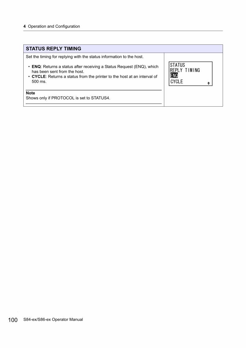
4 Operation and Configuration
100
STATUS REPLY TIMING
Set the timing for replying with the status information to the host.
• ENQ: Returns a status after receiving a Status Request (ENQ), which has been sent from the host.
• CYCLE: Returns a status from the printer to the host at an interval of 500 ms.
NoteShows only if PROTOCOL is set to STATUS4.
S84-ex/S86-ex Operator Manual
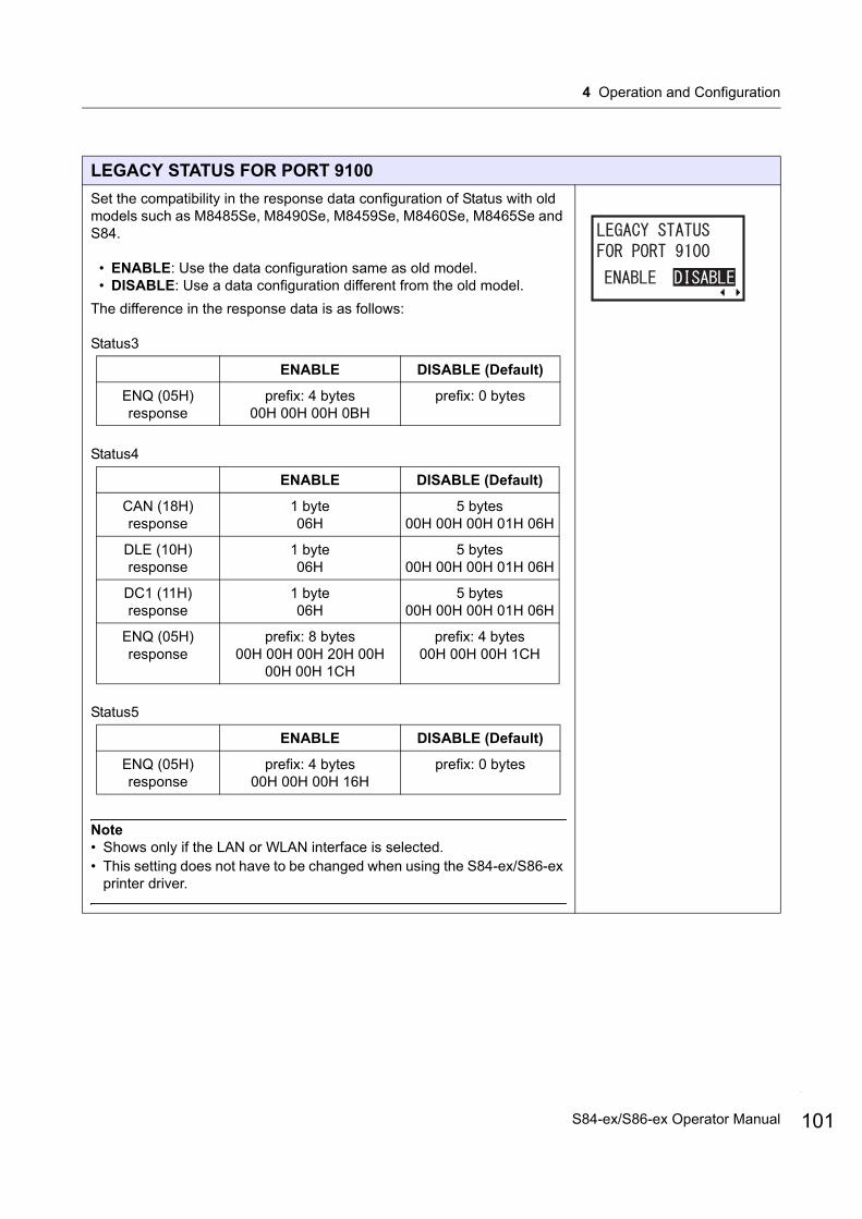
4 Operation and Configuration
LEGACY STATUS FOR PORT 9100
Set the compatibility in the response data configuration of Status with old models such as M8485Se, M8490Se, M8459Se, M8460Se, M8465Se and S84.
• ENABLE: Use the data configuration same as old model.• DISABLE: Use a data configuration different from the old model.
The difference in the response data is as follows:
Status3
Status4
Status5
Note• Shows only if the LAN or WLAN interface is selected.• This setting does not have to be changed when using the S84-ex/S86-ex
printer driver.
ENABLE DISABLE (Default)
ENQ (05H)response
prefix: 4 bytes00H 00H 00H 0BH
prefix: 0 bytes
ENABLE DISABLE (Default)
CAN (18H)response
1 byte06H
5 bytes00H 00H 00H 01H 06H
DLE (10H)response
1 byte06H
5 bytes00H 00H 00H 01H 06H
DC1 (11H)response
1 byte06H
5 bytes00H 00H 00H 01H 06H
ENQ (05H)response
prefix: 8 bytes00H 00H 00H 20H 00H
00H 00H 1CH
prefix: 4 bytes00H 00H 00H 1CH
ENABLE DISABLE (Default)
ENQ (05H)response
prefix: 4 bytes00H 00H 00H 16H
prefix: 0 bytes
101S84-ex/S86-ex Operator Manual
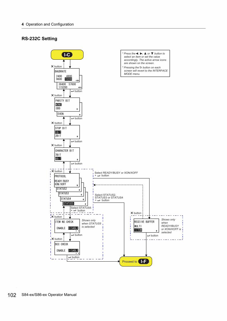
4 Operation and Configuration
102
RS-232C Setting
Select READY/BUSY or XON/XOFF + button
Select STATUS2, STATUS3 or STATUS4 + button
Shows only when STATUS5 is selected
Shows only when READY/BUSY or XON/XOFF is selected
* Press the , , or button to select an item or set the value accordingly. The active arrow icons are shown on the screen.
* Pressing the button on each screen will revert to the INTERFACE MODE menu.
button
buttonbutton
button
button
buttonbutton
button
button
buttonbutton
Select STATUS5 + button
button
button
buttonbutton
I-C
Proceed to .I-F
S84-ex/S86-ex Operator Manual
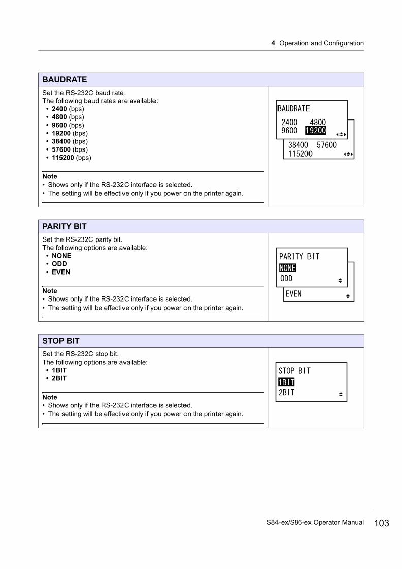
4 Operation and Configuration
BAUDRATE
Set the RS-232C baud rate.The following baud rates are available:
• 2400 (bps)• 4800 (bps)• 9600 (bps)• 19200 (bps)• 38400 (bps)• 57600 (bps)• 115200 (bps)
Note• Shows only if the RS-232C interface is selected.• The setting will be effective only if you power on the printer again.
PARITY BIT
Set the RS-232C parity bit.The following options are available:
• NONE• ODD• EVEN
Note• Shows only if the RS-232C interface is selected.• The setting will be effective only if you power on the printer again.
STOP BIT
Set the RS-232C stop bit.The following options are available:
• 1BIT• 2BIT
Note• Shows only if the RS-232C interface is selected.• The setting will be effective only if you power on the printer again.
103S84-ex/S86-ex Operator Manual
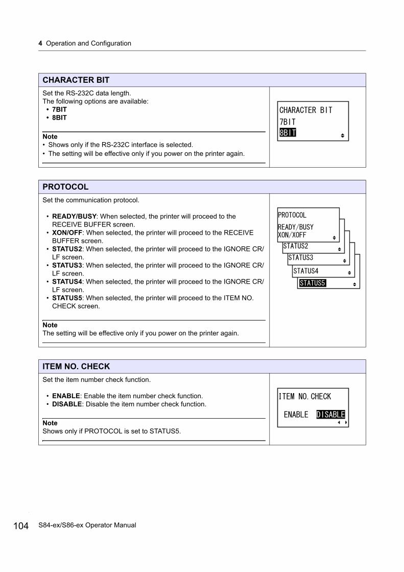
4 Operation and Configuration
104
CHARACTER BIT
Set the RS-232C data length.The following options are available:
• 7BIT• 8BIT
Note• Shows only if the RS-232C interface is selected.• The setting will be effective only if you power on the printer again.
PROTOCOL
Set the communication protocol.
• READY/BUSY: When selected, the printer will proceed to the RECEIVE BUFFER screen.
• XON/OFF: When selected, the printer will proceed to the RECEIVE BUFFER screen.
• STATUS2: When selected, the printer will proceed to the IGNORE CR/LF screen.
• STATUS3: When selected, the printer will proceed to the IGNORE CR/LF screen.
• STATUS4: When selected, the printer will proceed to the IGNORE CR/LF screen.
• STATUS5: When selected, the printer will proceed to the ITEM NO. CHECK screen.
NoteThe setting will be effective only if you power on the printer again.
ITEM NO. CHECK
Set the item number check function.
• ENABLE: Enable the item number check function.• DISABLE: Disable the item number check function.
NoteShows only if PROTOCOL is set to STATUS5.
S84-ex/S86-ex Operator Manual
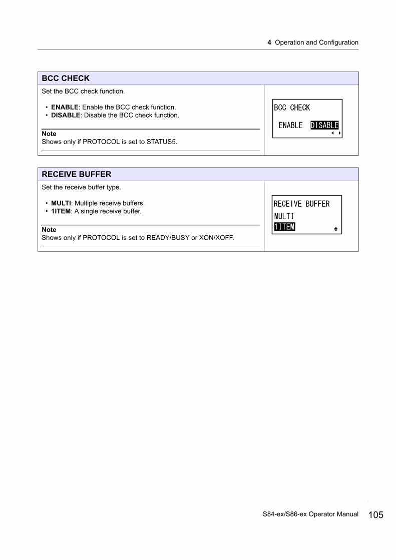
4 Operation and Configuration
BCC CHECK
Set the BCC check function.
• ENABLE: Enable the BCC check function.• DISABLE: Disable the BCC check function.
NoteShows only if PROTOCOL is set to STATUS5.
RECEIVE BUFFER
Set the receive buffer type.
• MULTI: Multiple receive buffers.• 1ITEM: A single receive buffer.
NoteShows only if PROTOCOL is set to READY/BUSY or XON/XOFF.
105S84-ex/S86-ex Operator Manual

4 Operation and Configuration
106
IEEE1284 Setting
Shows only when STATUS5 is selected
Shows only when STATUS4 is selected
Shows only when RECEIVE BUFFER is set to 1ITEM.
* Press the , , or button to select an item or set the value accordingly. The active arrow icons are shown on the screen.
* Pressing the button on each screen will revert to the INTERFACE MODE menu.
button
button
buttonbutton
button
button
button
button
button
button
I-D
Proceed to .I-F
S84-ex/S86-ex Operator Manual
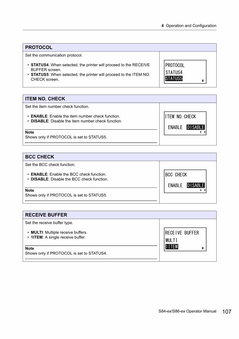
4 Operation and Configuration
PROTOCOL
Set the communication protocol.
• STATUS4: When selected, the printer will proceed to the RECEIVE BUFFER screen.
• STATUS5: When selected, the printer will proceed to the ITEM NO. CHECK screen.
ITEM NO. CHECK
Set the item number check function.
• ENABLE: Enable the item number check function.• DISABLE: Disable the item number check function.
NoteShows only if PROTOCOL is set to STATUS5.
BCC CHECK
Set the BCC check function.
• ENABLE: Enable the BCC check function.• DISABLE: Disable the BCC check function.
NoteShows only if PROTOCOL is set to STATUS5.
RECEIVE BUFFER
Set the receive buffer type.
• MULTI: Multiple receive buffers.• 1ITEM: A single receive buffer.
NoteShows only if PROTOCOL is set to STATUS4.
107S84-ex/S86-ex Operator Manual

4 Operation and Configuration
108
IEEE1284 ACK SIGNAL
Set the width of the IEEE1284 ACK signal.The setting range is from 00.5 µs to 12.0 µs, and is adjustable in 0.1 µs steps.
NoteShows only if the IEEE1284 interface is selected and RECEIVE BUFFER is set to 1ITEM.
S84-ex/S86-ex Operator Manual

4 Operation and Configuration
Bluetooth Setting
* Press the , , or button to select an item or set the value accordingly. The active arrow icons are shown on the screen.
* Pressing the button on each screen will revert to the INTERFACE MODE menu.
button
buttonbutton
buttonbutton
button
button
button
button
button
button button
button
button
button
buttonbutton
buttonbutton
button
Shows only when ENABLE is selected
I-E
Proceed to .I-F
109S84-ex/S86-ex Operator Manual
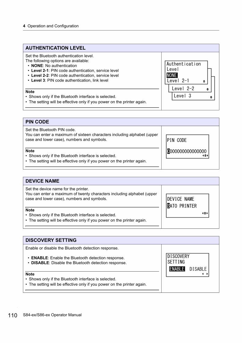
4 Operation and Configuration
110
AUTHENTICATION LEVEL
Set the Bluetooth authentication level.The following options are available:
• NONE: No authentication• Level 2-1: PIN code authentication, service level• Level 2-2: PIN code authentication, service level• Level 3: PIN code authentication, link level
Note• Shows only if the Bluetooth interface is selected.• The setting will be effective only if you power on the printer again.
PIN CODE
Set the Bluetooth PIN code.You can enter a maximum of sixteen characters including alphabet (upper case and lower case), numbers and symbols.
Note• Shows only if the Bluetooth interface is selected.• The setting will be effective only if you power on the printer again.
DEVICE NAME
Set the device name for the printer.You can enter a maximum of twenty characters including alphabet (upper case and lower case), numbers and symbols.
Note• Shows only if the Bluetooth interface is selected.• The setting will be effective only if you power on the printer again.
DISCOVERY SETTING
Enable or disable the Bluetooth detection response.
• ENABLE: Enable the Bluetooth detection response.• DISABLE: Disable the Bluetooth detection response.
Note• Shows only if the Bluetooth interface is selected.• The setting will be effective only if you power on the printer again.
S84-ex/S86-ex Operator Manual

4 Operation and Configuration
PARAMETER SETTING (ISI)
Set the Bluetooth communication parameter (ISI).The setting range is from 0012 to 1000.
Note• Shows only if the Bluetooth interface is selected and DETECTING
SETTING is enabled.• You cannot set the ISI value if it is smaller than the ISW value.• The setting will be effective only if you power on the printer again.
PARAMETER SETTING (ISW)
Set the Bluetooth communication parameter (ISW).The setting range is from 0011 to 1000.
Note• Shows only if the Bluetooth interface is selected and DETECTING
SETTING is enabled.• You cannot set the ISW value if it is greater than the ISI value.• The setting will be effective only if you power on the printer again.
PARAMETER SETTING (PSI)
Set the Bluetooth communication parameter (PSI).The setting range is from 0012 to 1000.
Note• Shows only if the Bluetooth interface is selected.• You cannot set the PSI value if it is smaller than the PSW value.• The setting will be effective only if you power on the printer again.
PARAMETER SETTING (PSW)
Set the Bluetooth communication parameter (PSW).The setting range is from 0011 to 1000.
Note• Shows only if the Bluetooth interface is selected.• You cannot set the PSW value if it is greater than the PSI value.• The setting will be effective only if you power on the printer again.
111S84-ex/S86-ex Operator Manual
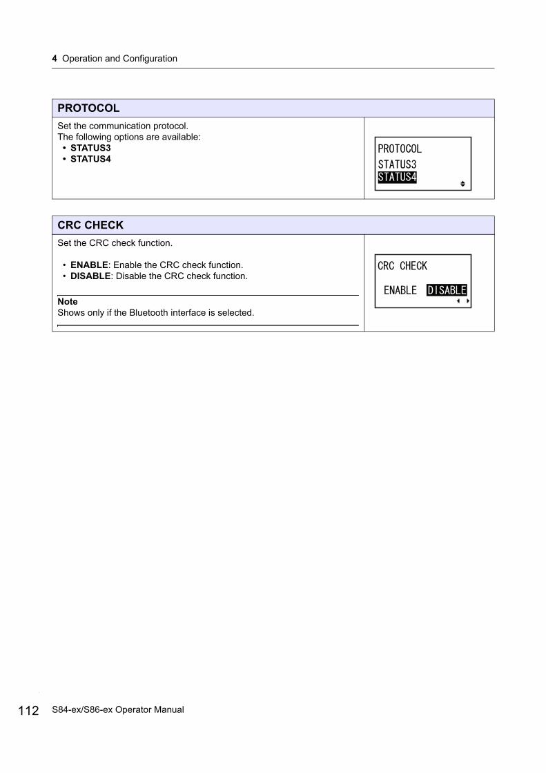
4 Operation and Configuration
112
PROTOCOL
Set the communication protocol.The following options are available:
• STATUS3• STATUS4
CRC CHECK
Set the CRC check function.
• ENABLE: Enable the CRC check function.• DISABLE: Disable the CRC check function.
NoteShows only if the Bluetooth interface is selected.
S84-ex/S86-ex Operator Manual
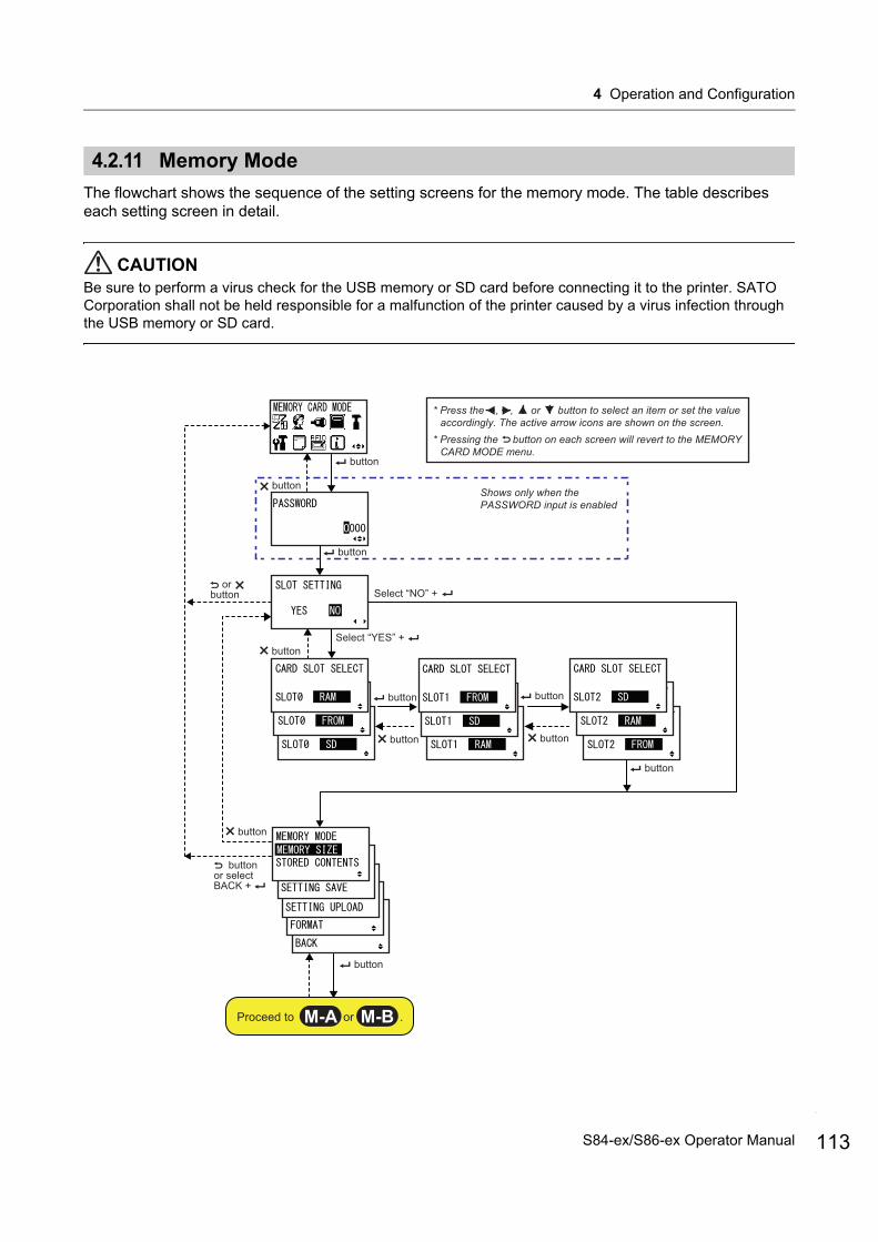
4 Operation and Configuration
4.2.11 Memory Mode
The flowchart shows the sequence of the setting screens for the memory mode. The table describes each setting screen in detail.
CAUTIONBe sure to perform a virus check for the USB memory or SD card before connecting it to the printer. SATO Corporation shall not be held responsible for a malfunction of the printer caused by a virus infection through the USB memory or SD card.
Shows only when the PASSWORD input is enabled
Select “NO” +
button
button
button
button
button
button
Select “YES” +
or button
buttonor selectBACK +
button
button button
button button
Proceed to or .M-A M-B
* Press the , , or button to select an item or set the value accordingly. The active arrow icons are shown on the screen.
* Pressing the button on each screen will revert to the MEMORY CARD MODE menu.
113S84-ex/S86-ex Operator Manual
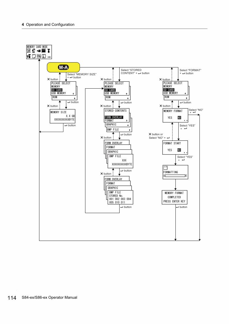
4 Operation and Configuration
114
button
buttonbutton
button
button
Select “STOREDCONTENT” + button
button
Select “FORMAT” + button
buttonbutton
buttonbutton
buttonbutton
buttonbutton
Select “YES” +
Select “NO” + button or
Select “NO” +
Select “YES” +
button button
Select “MEMORY SIZE” + button
M-A
S84-ex/S86-ex Operator Manual
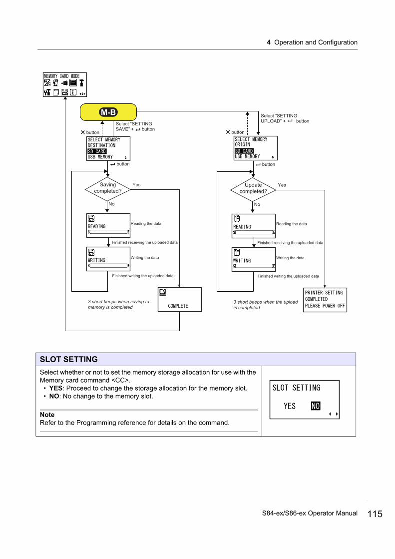
4 Operation and Configuration
SLOT SETTING
Select whether or not to set the memory storage allocation for use with the Memory card command <CC>.
• YES: Proceed to change the storage allocation for the memory slot.• NO: No change to the memory slot.
NoteRefer to the Programming reference for details on the command.
button
Select “SETTINGSAVE” + button
button
Select “SETTINGUPLOAD” + button
button
Savingcompleted?
Yes
No
Reading the data
Writing the data
Finished receiving the uploaded data
Finished writing the uploaded data
3 short beeps when saving to memory is completed
button
Updatecompleted?
Yes
No
Reading the data
Writing the data
Finished receiving the uploaded data
Finished writing the uploaded data
3 short beeps when the upload is completed
M-B
115S84-ex/S86-ex Operator Manual
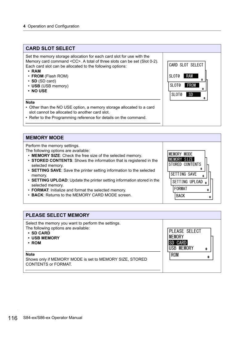
4 Operation and Configuration
116
CARD SLOT SELECT
Set the memory storage allocation for each card slot for use with the Memory card command <CC>. A total of three slots can be set (Slot 0-2).Each card slot can be allocated to the following options:
• RAM• FROM (Flash ROM)• SD (SD card)• USB (USB memory)• NO USE
Note• Other than the NO USE option, a memory storage allocated to a card
slot cannot be allocated to another card slot.• Refer to the Programming reference for details on the command.
MEMORY MODE
Perform the memory settings.The following options are available:
• MEMORY SIZE: Check the free size of the selected memory.• STORED CONTENTS: Shows the information that is registered in the
selected memory.• SETTING SAVE: Save the printer setting information to the selected
memory.• SETTING UPLOAD: Update the printer setting information stored in the
selected memory.• FORMAT: Initialize and format the selected memory.• BACK: Returns to the MEMORY CARD MODE screen.
PLEASE SELECT MEMORY
Select the memory you want to perform the settings.The following options are available:
• SD CARD• USB MEMORY• ROM
NoteShows only if MEMORY MODE is set to MEMORY SIZE, STORED CONTENTS or FORMAT.
S84-ex/S86-ex Operator Manual

4 Operation and Configuration
MEMORY SIZE
Check the free size of the selected memory.The memory unit (BYTE, KB, MB, GB) changes automatically according to the free space of the memory.
Note
After you press the ENTER button, the screen returns to MEMORY CARD MODE.
STORED CONTENTS
Select the type of information registered in the memory.The following options are available:
• FORM OVERLAY• FORMAT• GRAPHIC• BMP FILE
MEMORY INFORMATION
Shows the number of files and total size of the selected type of information registered in the memory.
The maximum number of files is 999.
STORED NO. INFORMATION
Shows the stored number of the registered information.
The stored number range is from 001 to 999.
Note
After you press the ENTER button, the screen returns to PLEASE SELECT MEMORY.
117S84-ex/S86-ex Operator Manual
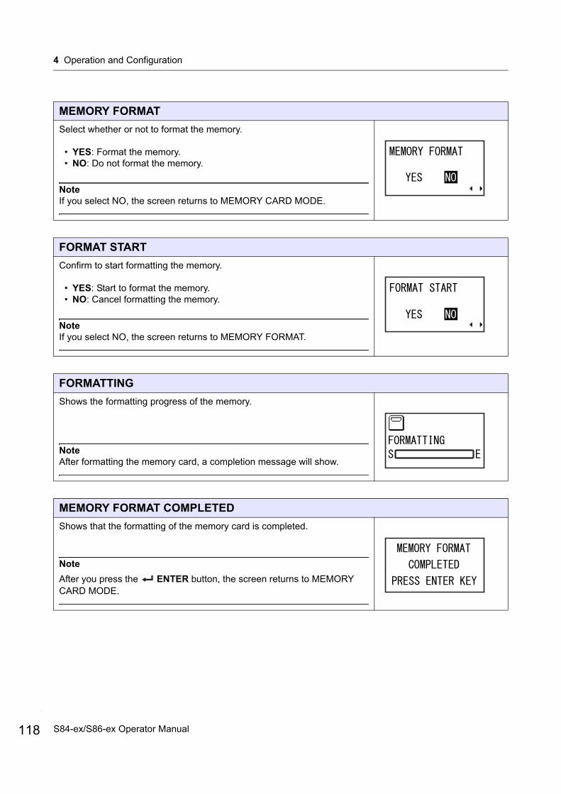
4 Operation and Configuration
118
MEMORY FORMAT
Select whether or not to format the memory.
• YES: Format the memory.• NO: Do not format the memory.
NoteIf you select NO, the screen returns to MEMORY CARD MODE.
FORMAT START
Confirm to start formatting the memory.
• YES: Start to format the memory.• NO: Cancel formatting the memory.
NoteIf you select NO, the screen returns to MEMORY FORMAT.
FORMATTING
Shows the formatting progress of the memory.
NoteAfter formatting the memory card, a completion message will show.
MEMORY FORMAT COMPLETED
Shows that the formatting of the memory card is completed.
Note
After you press the ENTER button, the screen returns to MEMORY CARD MODE.
S84-ex/S86-ex Operator Manual
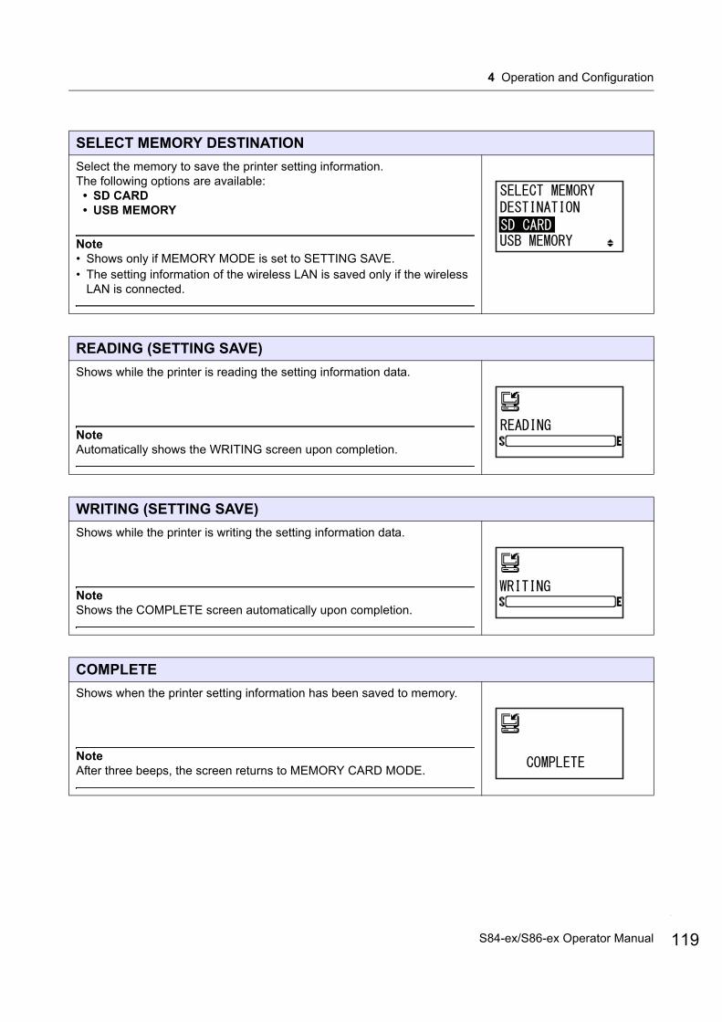
4 Operation and Configuration
SELECT MEMORY DESTINATION
Select the memory to save the printer setting information. The following options are available:
• SD CARD• USB MEMORY
Note• Shows only if MEMORY MODE is set to SETTING SAVE.• The setting information of the wireless LAN is saved only if the wireless
LAN is connected.
READING (SETTING SAVE)
Shows while the printer is reading the setting information data.
NoteAutomatically shows the WRITING screen upon completion.
WRITING (SETTING SAVE)
Shows while the printer is writing the setting information data.
NoteShows the COMPLETE screen automatically upon completion.
COMPLETE
Shows when the printer setting information has been saved to memory.
NoteAfter three beeps, the screen returns to MEMORY CARD MODE.
119S84-ex/S86-ex Operator Manual
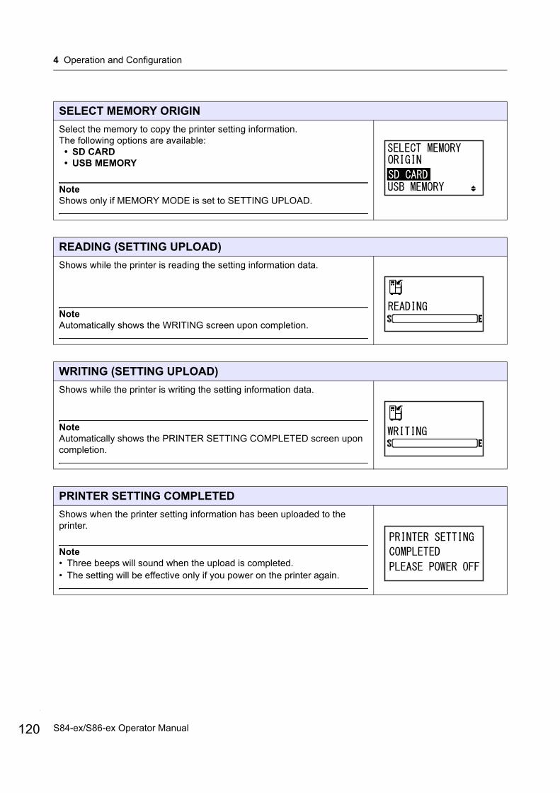
4 Operation and Configuration
120
SELECT MEMORY ORIGIN
Select the memory to copy the printer setting information. The following options are available:
• SD CARD• USB MEMORY
NoteShows only if MEMORY MODE is set to SETTING UPLOAD.
READING (SETTING UPLOAD)
Shows while the printer is reading the setting information data.
NoteAutomatically shows the WRITING screen upon completion.
WRITING (SETTING UPLOAD)
Shows while the printer is writing the setting information data.
NoteAutomatically shows the PRINTER SETTING COMPLETED screen upon completion.
PRINTER SETTING COMPLETED
Shows when the printer setting information has been uploaded to the printer.
Note• Three beeps will sound when the upload is completed.• The setting will be effective only if you power on the printer again.
S84-ex/S86-ex Operator Manual
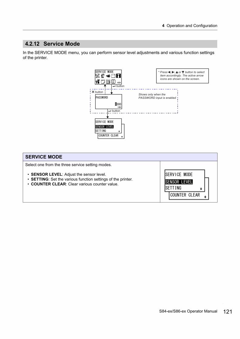
4 Operation and Configuration
4.2.12 Service Mode
In the SERVICE MODE menu, you can perform sensor level adjustments and various function settings of the printer.
SERVICE MODE
Select one from the three service setting modes.
• SENSOR LEVEL: Adjust the sensor level.• SETTING: Set the various function settings of the printer.• COUNTER CLEAR: Clear various counter value.
* Press , , or button to select item accordingly. The active arrow icons are shown on the screen.
Shows only when the PASSWORD input is enabled
button
button
button
121S84-ex/S86-ex Operator Manual

4 Operation and Configuration
122
Sensor Level AdjustmentsThe flowchart shows the sequence of the setting screens for the sensor level adjustments. The table describes each setting screen in detail.
button
buttonbutton
Select SENSOR LEVEL + button
button
Select AUTO + button
Select RETRY + button
* Press the , , or button to select an item or set the value accordingly. The active arrow icons are shown on the screen.
* Pressing the button on each screen will revert to the SERVICE MODE setting screen.
button
button
button
Select MANUAL + button
button
button
button
button
button
button
button
button
button
When I-MARK is selected When GAP is selected
Calibration succeed. Calibration failed.
button
button
Select EXIT CALIBRATION+ button
S84-ex/S86-ex Operator Manual
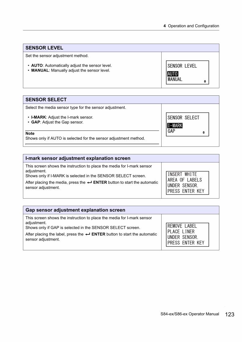
4 Operation and Configuration
SENSOR LEVEL
Set the sensor adjustment method.
• AUTO: Automatically adjust the sensor level.• MANUAL: Manually adjust the sensor level.
SENSOR SELECT
Select the media sensor type for the sensor adjustment.
• I-MARK: Adjust the I-mark sensor.• GAP: Adjust the Gap sensor.
NoteShows only if AUTO is selected for the sensor adjustment method.
I-mark sensor adjustment explanation screen
This screen shows the instruction to place the media for I-mark sensor adjustment.Shows only if I-MARK is selected in the SENSOR SELECT screen.
After placing the media, press the ENTER button to start the automatic sensor adjustment.
Gap sensor adjustment explanation screen
This screen shows the instruction to place the media for I-mark sensor adjustment.Shows only if GAP is selected in the SENSOR SELECT screen.
After placing the label, press the ENTER button to start the automatic sensor adjustment.
123S84-ex/S86-ex Operator Manual
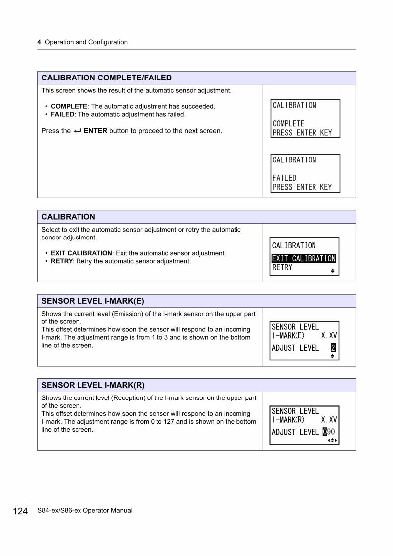
4 Operation and Configuration
124
CALIBRATION COMPLETE/FAILED
This screen shows the result of the automatic sensor adjustment.
• COMPLETE: The automatic adjustment has succeeded.• FAILED: The automatic adjustment has failed.
Press the ENTER button to proceed to the next screen.
CALIBRATION
Select to exit the automatic sensor adjustment or retry the automatic sensor adjustment.
• EXIT CALIBRATION: Exit the automatic sensor adjustment.• RETRY: Retry the automatic sensor adjustment.
SENSOR LEVEL I-MARK(E)
Shows the current level (Emission) of the I-mark sensor on the upper part of the screen.This offset determines how soon the sensor will respond to an incoming I-mark. The adjustment range is from 1 to 3 and is shown on the bottom line of the screen.
SENSOR LEVEL I-MARK(R)
Shows the current level (Reception) of the I-mark sensor on the upper part of the screen.This offset determines how soon the sensor will respond to an incoming I-mark. The adjustment range is from 0 to 127 and is shown on the bottom line of the screen.
S84-ex/S86-ex Operator Manual
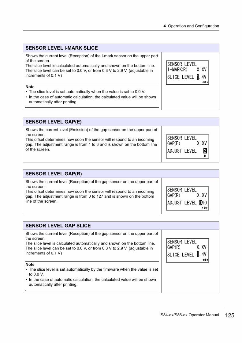
4 Operation and Configuration
SENSOR LEVEL I-MARK SLICE
Shows the current level (Reception) of the I-mark sensor on the upper part of the screen.The slice level is calculated automatically and shown on the bottom line.The slice level can be set to 0.0 V, or from 0.3 V to 2.9 V. (adjustable in increments of 0.1 V)
Note• The slice level is set automatically when the value is set to 0.0 V.• In the case of automatic calculation, the calculated value will be shown
automatically after printing.
SENSOR LEVEL GAP(E)
Shows the current level (Emission) of the gap sensor on the upper part of the screen.This offset determines how soon the sensor will respond to an incoming gap. The adjustment range is from 1 to 3 and is shown on the bottom line of the screen.
SENSOR LEVEL GAP(R)
Shows the current level (Reception) of the gap sensor on the upper part of the screen.This offset determines how soon the sensor will respond to an incoming gap. The adjustment range is from 0 to 127 and is shown on the bottom line of the screen.
SENSOR LEVEL GAP SLICE
Shows the current level (Reception) of the gap sensor on the upper part of the screen.The slice level is calculated automatically and shown on the bottom line.The slice level can be set to 0.0 V, or from 0.3 V to 2.9 V. (adjustable in increments of 0.1 V)
Note• The slice level is set automatically by the firmware when the value is set
to 0.0 V.• In the case of automatic calculation, the calculated value will be shown
automatically after printing.
125S84-ex/S86-ex Operator Manual
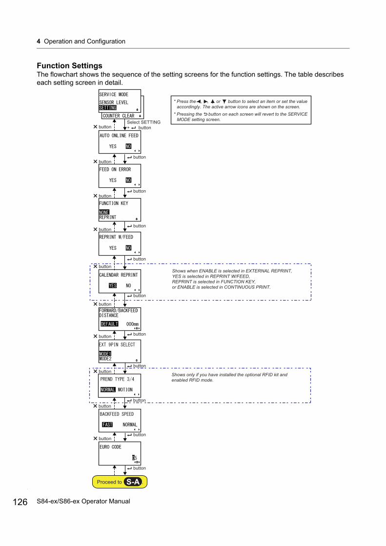
4 Operation and Configuration
126
Function SettingsThe flowchart shows the sequence of the setting screens for the function settings. The table describes each setting screen in detail.
buttonbutton
buttonSelect SETTING + button
Shows when ENABLE is selected in EXTERNAL REPRINT, YES is selected in REPRINT W/FEED,REPRINT is selected in FUNCTION KEY,or ENABLE is selected in CONTINUOUS PRINT.
buttonbutton
buttonbutton
button
button
button
button
buttonbutton
buttonbutton
buttonbutton
button
Proceed to .S-A
* Press the , , or button to select an item or set the value accordingly. The active arrow icons are shown on the screen.
* Pressing the button on each screen will revert to the SERVICE MODE setting screen.
buttonbutton
Shows only if you have installed the optional RFID kit and enabled RFID mode.
S84-ex/S86-ex Operator Manual
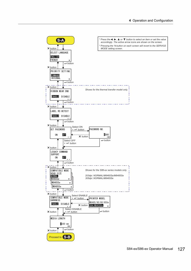
4 Operation and Configuration
button
button
button
button
button
button
button
button
button
Shows for the thermal transfer model only.
button
button
button
button
button
button
Select ON+ button
Shows for the S86-ex series models only.
203dpi: NORMAL/M8460Se/M8485Se305dpi: NORMAL/M8465Se
button
S-A
Proceed to .S-B
* Press the , , or button to select an item or set the value accordingly. The active arrow icons are shown on the screen.
* Pressing the button on each screen will revert to the SERVICE MODE setting screen.
Select OFF+ button
button
button
Select ENABLE+ button
Select DISABLE+ buttonbutton
button
button
127S84-ex/S86-ex Operator Manual

4 Operation and Configuration
128
button
button
button
button
button
Shows only when SAVE PRINT LOG is set to ENABLE.
buttonbutton
buttonbutton
button
button
button
button
button
button
buttonbutton
Shows only for the thermal transfer model.
Shows only if PRINTER TYPE is set to LINERLESS.
S-B
Proceed to .S-C
* Press the , , or button to select an item or set the value accordingly. The active arrow icons are shown on the screen.
* Pressing the button on each screen will revert to the SERVICE MODE setting screen.
button
S84-ex/S86-ex Operator Manual

4 Operation and Configuration
buttonbutton
button
button
buttonbutton
buttonbutton
buttonbutton
buttonbutton
Waiting to be powered off.
S-C* Press the , , or button to select an item or set the value
accordingly. The active arrow icons are shown on the screen.* Pressing the button on each screen will revert to the SERVICE
MODE setting screen.
button
Select YES + button and when there are changes in printer settings.
Select NO + button
Returns to SERVICE MODE setting screen or MAINTENANCE MODE menu.
buttonbutton
203dpi Shows for the S86-ex series models only.305dpi
129S84-ex/S86-ex Operator Manual

4 Operation and Configuration
130
AUTO ONLINE FEED
Set the auto online feed function.This function enables the printer to automatically feed media in online mode after power on.
• YES: Feed the media in online mode at power on.• NO: Do not feed the media in online mode at power on.
FEED ON ERROR
Set the online feed function.This function enables the printer to feed media automatically when recovering from a head open error or when starting up the printer and changing to online mode.
• YES: Feed the media when changing to online mode.• NO: Do not feed the media when changing to online mode.
FUNCTION KEY
Allocate the following functions to the FUNCTION button.
• NONE: Do not allocate any function.• REPRINT: Allocate the reprint function.
Note
The FUNCTION button is disabled when NONE is set.
REPRINT W/FEED
Enable or disable the reprint function using the FEED button.If this function is enabled, you can reprint the last print job by pressing the
FEED button in online mode.
• YES: Enable the reprint function.• NO: Disable the reprint function.
S84-ex/S86-ex Operator Manual

4 Operation and Configuration
CALENDAR REPRINT
Perform the calendar reprint setting.
• YES: The updated calendar data (date and time) according to the RTC (Real Time Clock) is included in the reprint data.
• NO: Print exactly the same data as before.
NoteShows only if EXTERNAL REPRINT is set to ENABLE, REPRINT W/FEED is set to YES, FUNCTION KEY is set to REPRINT, or CONTINUOUS PRINT is set to ENABLE.
FORWARD/BACKFEED DISTANCE
Set the feed length in the forward and backward directions.• DEFAULT: Enable the printer to operate using the fixed value
maintained in the printer.• 000mm: Set the feed length to enable the printer to operate using this
distance. The setting range of forward/backward feed length is from 001 mm to 255 mm (0.04” to 10”).The actual forward/backward feed length is equivalent to the offset adjustment value + the paper feed length.
Note• If using thermal transfer for printing, set the feed distance to less than
30 mm (1.2”) to avoid detection of the ribbon end by mistake.• If the value is larger than the distance between the print head and the
option stop position, the media may shift away from the platen during backward feed.
EXT 9PIN SELECT
Set the output mode of the external signal pin 9 when using a 14-pin connector (pin 6 when using a 25-pin connector).
• MODE1: The output signal becomes “Active” when there is remaining print data without error in online mode.
• MODE2: The output signal becomes “Active” when the printer is ONLINE.
NoteRefer to the Timing Chart of the EXT Output Signal (Online) for details.
131S84-ex/S86-ex Operator Manual
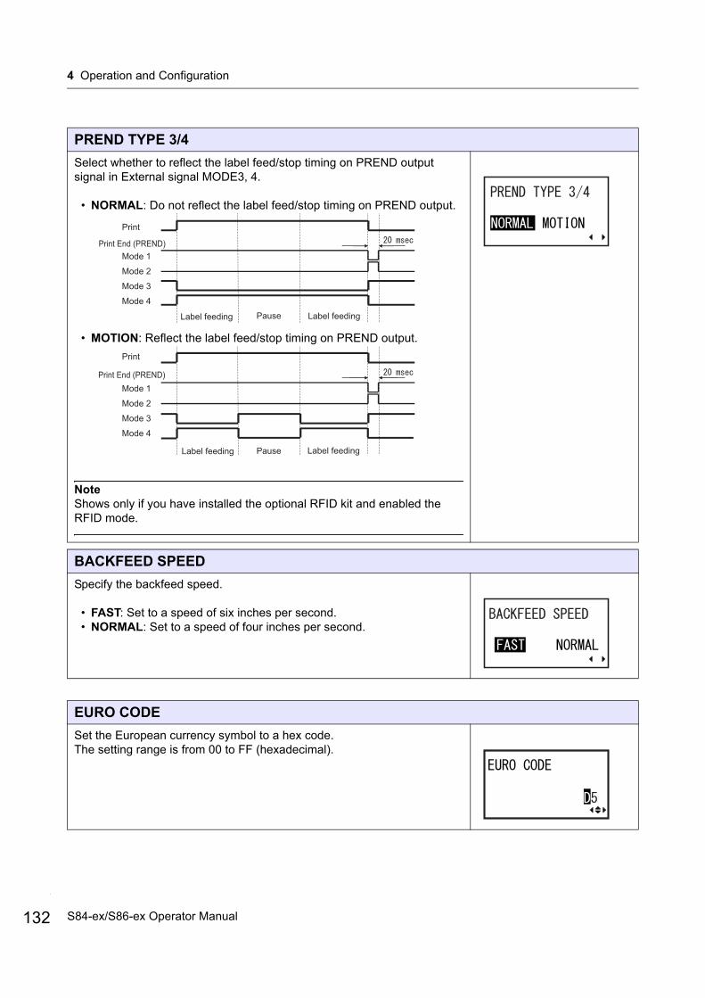
4 Operation and Configuration
132
PREND TYPE 3/4
Select whether to reflect the label feed/stop timing on PREND output signal in External signal MODE3, 4.
• NORMAL: Do not reflect the label feed/stop timing on PREND output.
• MOTION: Reflect the label feed/stop timing on PREND output.
NoteShows only if you have installed the optional RFID kit and enabled the RFID mode.
BACKFEED SPEED
Specify the backfeed speed.
• FAST: Set to a speed of six inches per second.• NORMAL: Set to a speed of four inches per second.
EURO CODE
Set the European currency symbol to a hex code.The setting range is from 00 to FF (hexadecimal).
Print End (PREND)
Label feeding Label feeding Pause
Mode 1
Mode 2
Mode 3
Mode 4
Print End (PREND)
Label feeding Label feeding Pause
Mode 1
Mode 2
Mode 3
Mode 4
S84-ex/S86-ex Operator Manual
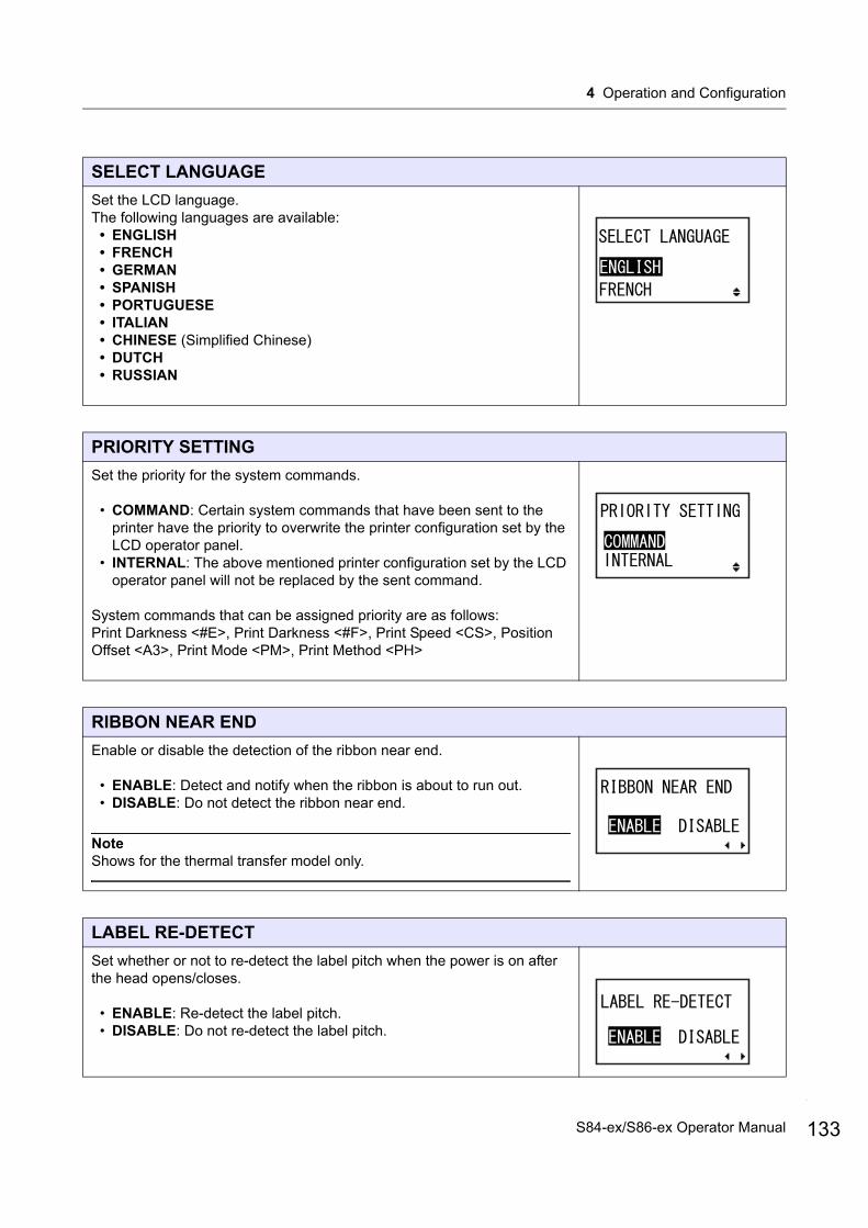
4 Operation and Configuration
SELECT LANGUAGE
Set the LCD language.The following languages are available:
• ENGLISH• FRENCH• GERMAN• SPANISH• PORTUGUESE• ITALIAN• CHINESE (Simplified Chinese)• DUTCH• RUSSIAN
PRIORITY SETTING
Set the priority for the system commands.
• COMMAND: Certain system commands that have been sent to the printer have the priority to overwrite the printer configuration set by the LCD operator panel.
• INTERNAL: The above mentioned printer configuration set by the LCD operator panel will not be replaced by the sent command.
System commands that can be assigned priority are as follows:Print Darkness <#E>, Print Darkness <#F>, Print Speed <CS>, Position Offset <A3>, Print Mode <PM>, Print Method <PH>
RIBBON NEAR END
Enable or disable the detection of the ribbon near end.
• ENABLE: Detect and notify when the ribbon is about to run out.• DISABLE: Do not detect the ribbon near end.
NoteShows for the thermal transfer model only.
LABEL RE-DETECT
Set whether or not to re-detect the label pitch when the power is on after the head opens/closes.
• ENABLE: Re-detect the label pitch.• DISABLE: Do not re-detect the label pitch.
133S84-ex/S86-ex Operator Manual
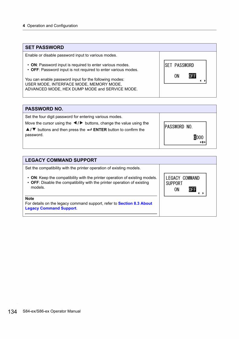
4 Operation and Configuration
134
SET PASSWORD
Enable or disable password input to various modes.
• ON: Password input is required to enter various modes.• OFF: Password input is not required to enter various modes.
You can enable password input for the following modes:USER MODE, INTERFACE MODE, MEMORY MODE,ADVANCED MODE, HEX DUMP MODE and SERVICE MODE.
PASSWORD NO.
Set the four digit password for entering various modes.
Move the cursor using the / buttons, change the value using the
/ buttons and then press the ENTER button to confirm the password.
LEGACY COMMAND SUPPORT
Set the compatibility with the printer operation of existing models.
• ON: Keep the compatibility with the printer operation of existing models.• OFF: Disable the compatibility with the printer operation of existing
models.
NoteFor details on the legacy command support, refer to Section 8.3 About Legacy Command Support.
S84-ex/S86-ex Operator Manual
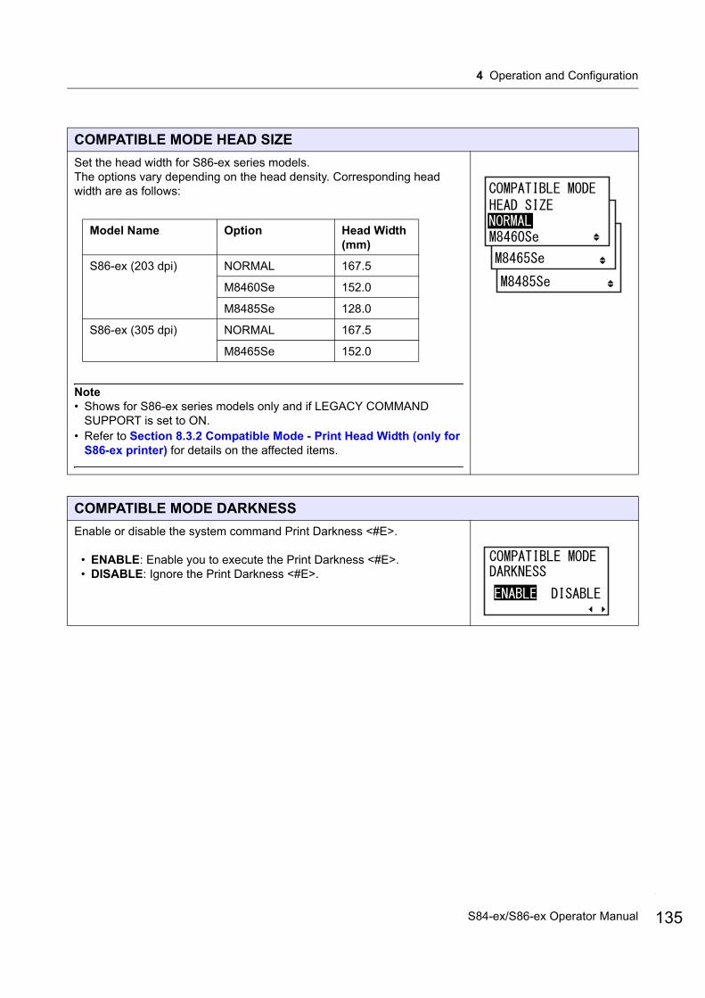
4 Operation and Configuration
COMPATIBLE MODE HEAD SIZE
Set the head width for S86-ex series models.The options vary depending on the head density. Corresponding head width are as follows:
Note• Shows for S86-ex series models only and if LEGACY COMMAND
SUPPORT is set to ON.• Refer to Section 8.3.2 Compatible Mode - Print Head Width (only for
S86-ex printer) for details on the affected items.
COMPATIBLE MODE DARKNESS
Enable or disable the system command Print Darkness <#E>.
• ENABLE: Enable you to execute the Print Darkness <#E>.• DISABLE: Ignore the Print Darkness <#E>.
Model Name Option Head Width (mm)
S86-ex (203 dpi) NORMAL 167.5
M8460Se 152.0
M8485Se 128.0
S86-ex (305 dpi) NORMAL 167.5
M8465Se 152.0
135S84-ex/S86-ex Operator Manual
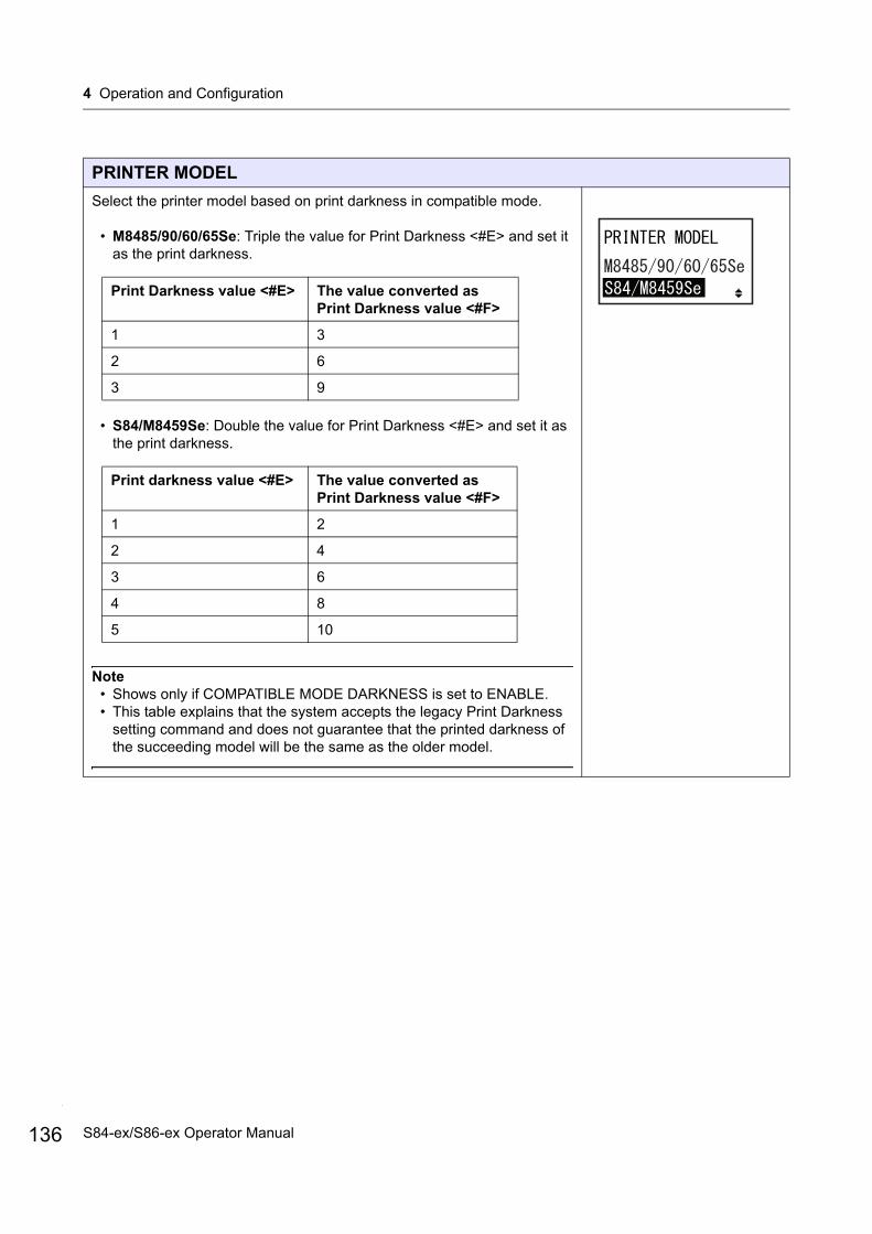
4 Operation and Configuration
136
PRINTER MODEL
Select the printer model based on print darkness in compatible mode.
• M8485/90/60/65Se: Triple the value for Print Darkness <#E> and set it as the print darkness.
• S84/M8459Se: Double the value for Print Darkness <#E> and set it as the print darkness.
Note• Shows only if COMPATIBLE MODE DARKNESS is set to ENABLE.• This table explains that the system accepts the legacy Print Darkness
setting command and does not guarantee that the printed darkness of the succeeding model will be the same as the older model.
Print Darkness value <#E> The value converted as Print Darkness value <#F>
1 3
2 6
3 9
Print darkness value <#E> The value converted as Print Darkness value <#F>
1 2
2 4
3 6
4 8
5 10
S84-ex/S86-ex Operator Manual
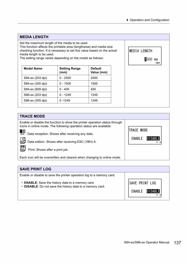
4 Operation and Configuration
MEDIA LENGTH
Set the maximum length of the media to be used.This function affects the printable area (lengthwise) and media size checking function. It is necessary to set this value based on the actual media length to be used.The setting range varies depending on the model as follows:
TRACE MODE
Enable or disable the function to show the printer operation status through icons in online mode. The following operation status are available:
: Data reception: Shows after receiving any data.
: Data edition: Shows after receiving ESC (1BH) A.
Print: Shows after a print job.
Each icon will be overwritten and cleared when changing to online mode.
SAVE PRINT LOG
Enable or disable to save the printer operation log to a memory card.
• ENABLE: Save the history data to a memory card.• DISABLE: Do not save the history data to a memory card.
Model Name Setting Range (mm)
Default Value (mm)
S84-ex (203 dpi) 0 - 2500 2500
S84-ex (305 dpi) 0 - 1500 1500
S84-ex (609 dpi) 0 - 400 400
S86-ex (203 dpi) 0 - 1249 1249
S86-ex (305 dpi) 0 -1249 1249
137S84-ex/S86-ex Operator Manual
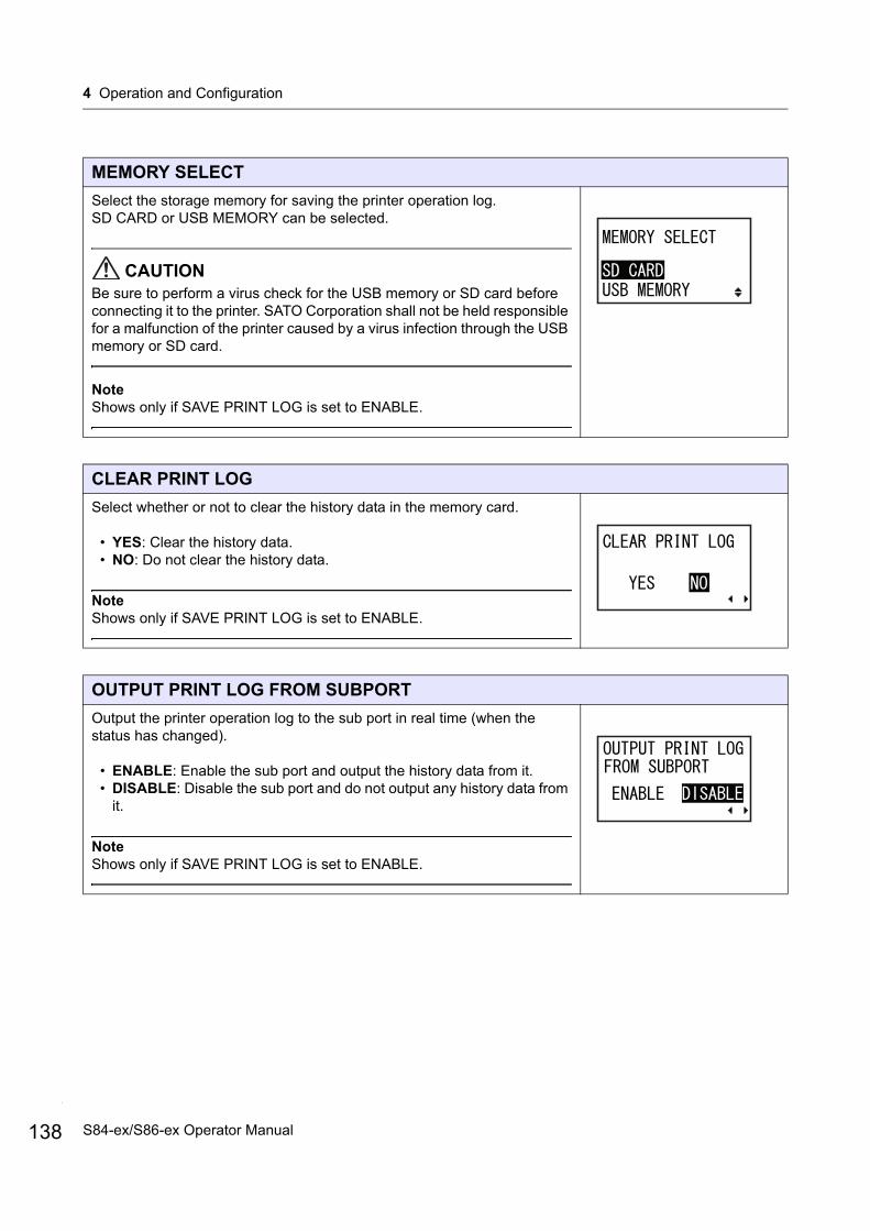
4 Operation and Configuration
138
MEMORY SELECT
Select the storage memory for saving the printer operation log.SD CARD or USB MEMORY can be selected.
CAUTIONBe sure to perform a virus check for the USB memory or SD card before connecting it to the printer. SATO Corporation shall not be held responsible for a malfunction of the printer caused by a virus infection through the USB memory or SD card.
NoteShows only if SAVE PRINT LOG is set to ENABLE.
CLEAR PRINT LOG
Select whether or not to clear the history data in the memory card.
• YES: Clear the history data.• NO: Do not clear the history data.
NoteShows only if SAVE PRINT LOG is set to ENABLE.
OUTPUT PRINT LOG FROM SUBPORT
Output the printer operation log to the sub port in real time (when the status has changed).
• ENABLE: Enable the sub port and output the history data from it.• DISABLE: Disable the sub port and do not output any history data from
it.
NoteShows only if SAVE PRINT LOG is set to ENABLE.
S84-ex/S86-ex Operator Manual
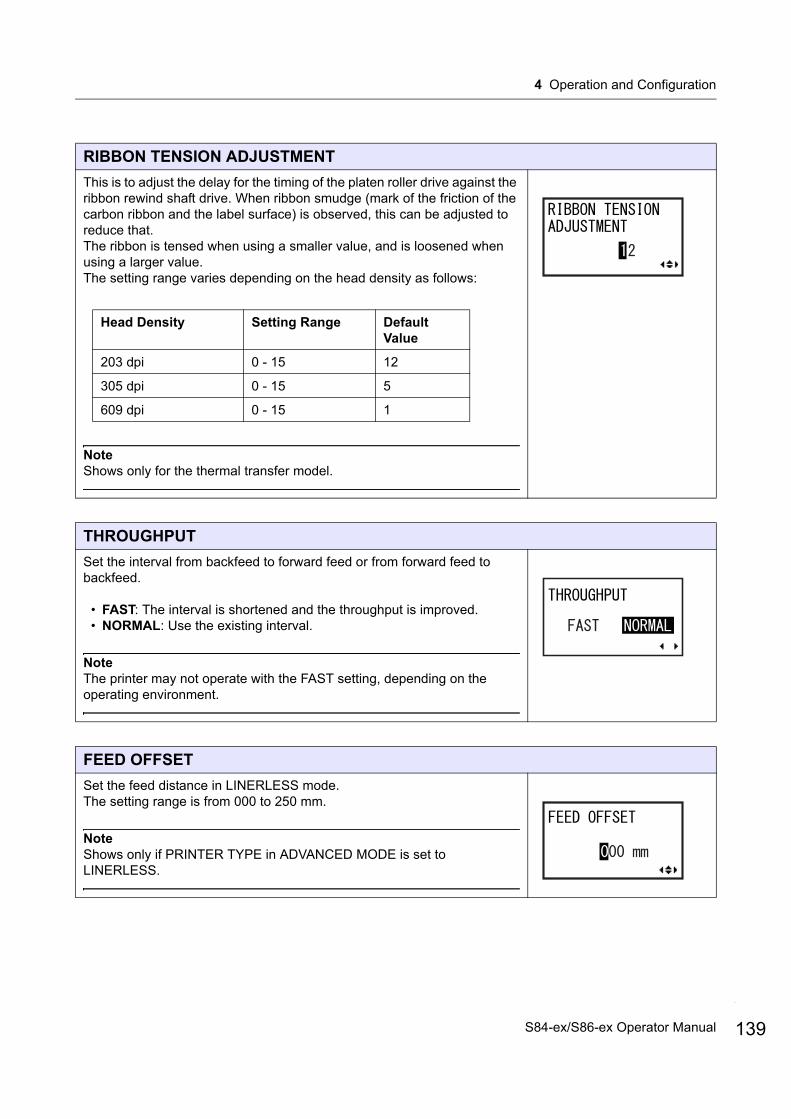
4 Operation and Configuration
RIBBON TENSION ADJUSTMENT
This is to adjust the delay for the timing of the platen roller drive against the ribbon rewind shaft drive. When ribbon smudge (mark of the friction of the carbon ribbon and the label surface) is observed, this can be adjusted to reduce that.The ribbon is tensed when using a smaller value, and is loosened when using a larger value.The setting range varies depending on the head density as follows:
NoteShows only for the thermal transfer model.
THROUGHPUT
Set the interval from backfeed to forward feed or from forward feed to backfeed.
• FAST: The interval is shortened and the throughput is improved.• NORMAL: Use the existing interval.
NoteThe printer may not operate with the FAST setting, depending on the operating environment.
FEED OFFSET
Set the feed distance in LINERLESS mode.The setting range is from 000 to 250 mm.
NoteShows only if PRINTER TYPE in ADVANCED MODE is set to LINERLESS.
Head Density Setting Range Default Value
203 dpi 0 - 15 12
305 dpi 0 - 15 5
609 dpi 0 - 15 1
139S84-ex/S86-ex Operator Manual

4 Operation and Configuration
140
BACKFEED OFFSET
Set the backfeed distance in LINERLESS mode.The setting range is from 000 to 250 mm.
NoteShows only if PRINTER TYPE in ADVANCED MODE is set to LINERLESS.
TOTAL QTY DISPLAY
Set whether or not to show the total print quantity.
• YES: Shows the total print quantity and current print quantity.• NO: Shows the current print quantity.
YES is selected NO is selected
PLUG & PLAY
Enable or disable the Plug and play function of the printer.
• ENABLE: Enable the Plug and play function.• DISABLE: Disable the Plug and play function.
NoteThis function will affect the IEEE1284 interface connectivity because it uses the DEVICE ID response of the IEEE1284.
S84-ex/S86-ex Operator Manual
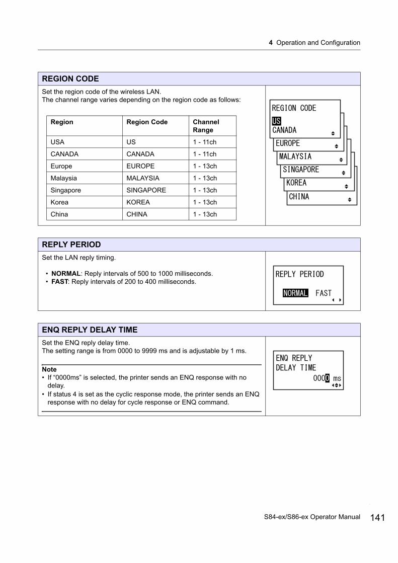
4 Operation and Configuration
REGION CODE
Set the region code of the wireless LAN.The channel range varies depending on the region code as follows:
REPLY PERIOD
Set the LAN reply timing.
• NORMAL: Reply intervals of 500 to 1000 milliseconds.• FAST: Reply intervals of 200 to 400 milliseconds.
ENQ REPLY DELAY TIME
Set the ENQ reply delay time.The setting range is from 0000 to 9999 ms and is adjustable by 1 ms.
Note• If “0000ms” is selected, the printer sends an ENQ response with no
delay.• If status 4 is set as the cyclic response mode, the printer sends an ENQ
response with no delay for cycle response or ENQ command.
Region Region Code Channel Range
USA US 1 - 11ch
CANADA CANADA 1 - 11ch
Europe EUROPE 1 - 13ch
Malaysia MALAYSIA 1 - 13ch
Singapore SINGAPORE 1 - 13ch
Korea KOREA 1 - 13ch
China CHINA 1 - 13ch
141S84-ex/S86-ex Operator Manual
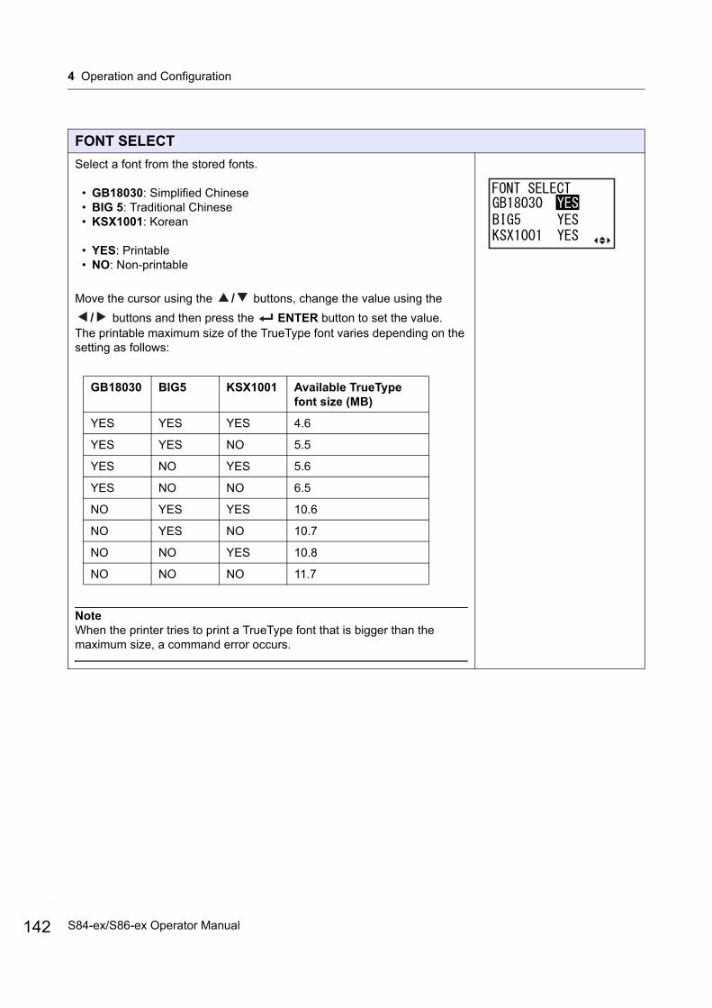
4 Operation and Configuration
142
FONT SELECT
Select a font from the stored fonts.
• GB18030: Simplified Chinese• BIG 5: Traditional Chinese• KSX1001: Korean
• YES: Printable• NO: Non-printable
Move the cursor using the / buttons, change the value using the
/ buttons and then press the ENTER button to set the value.The printable maximum size of the TrueType font varies depending on the setting as follows:
NoteWhen the printer tries to print a TrueType font that is bigger than the maximum size, a command error occurs.
GB18030 BIG5 KSX1001 Available TrueType font size (MB)
YES YES YES 4.6
YES YES NO 5.5
YES NO YES 5.6
YES NO NO 6.5
NO YES YES 10.6
NO YES NO 10.7
NO NO YES 10.8
NO NO NO 11.7
S84-ex/S86-ex Operator Manual
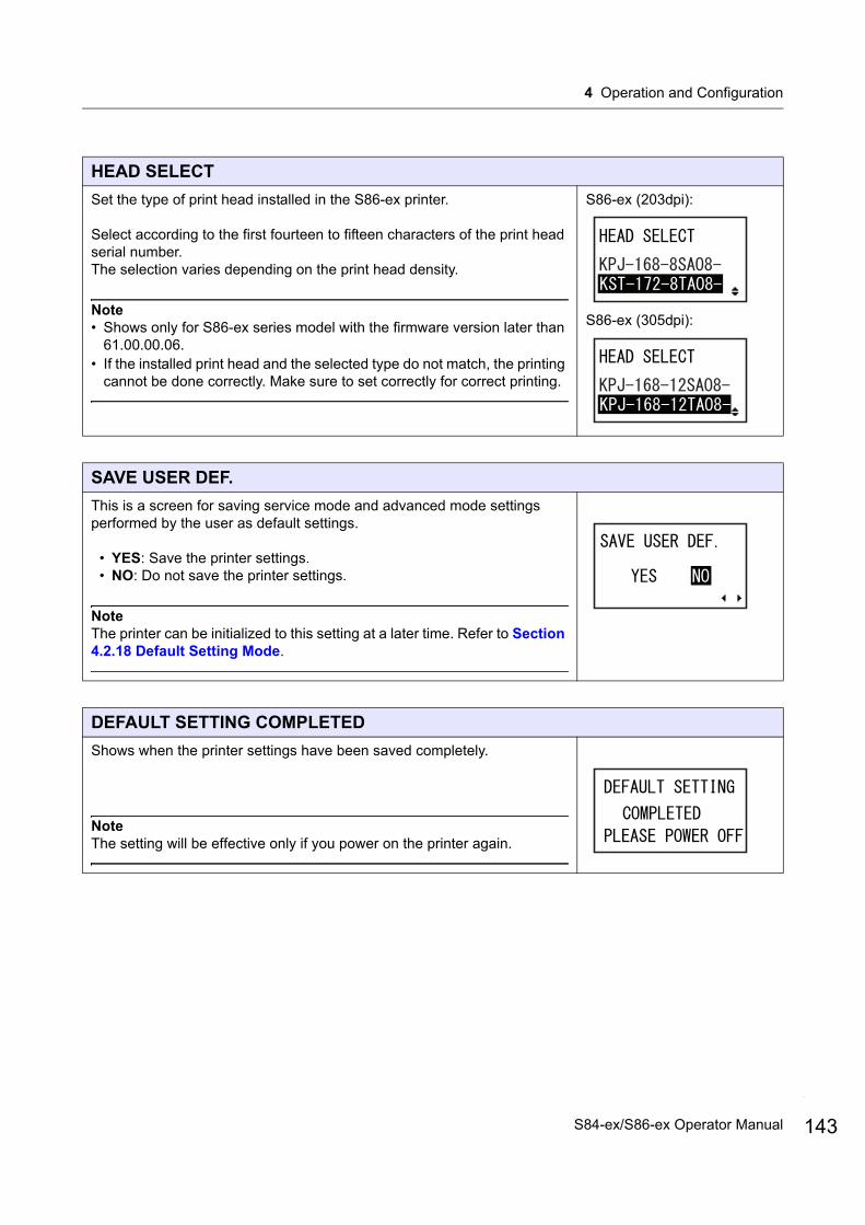
4 Operation and Configuration
HEAD SELECT
Set the type of print head installed in the S86-ex printer.
Select according to the first fourteen to fifteen characters of the print head serial number.The selection varies depending on the print head density.
Note• Shows only for S86-ex series model with the firmware version later than
61.00.00.06.• If the installed print head and the selected type do not match, the printing
cannot be done correctly. Make sure to set correctly for correct printing.
S86-ex (203dpi):
S86-ex (305dpi):
SAVE USER DEF.
This is a screen for saving service mode and advanced mode settings performed by the user as default settings.
• YES: Save the printer settings.• NO: Do not save the printer settings.
NoteThe printer can be initialized to this setting at a later time. Refer to Section 4.2.18 Default Setting Mode.
DEFAULT SETTING COMPLETED
Shows when the printer settings have been saved completely.
NoteThe setting will be effective only if you power on the printer again.
143S84-ex/S86-ex Operator Manual
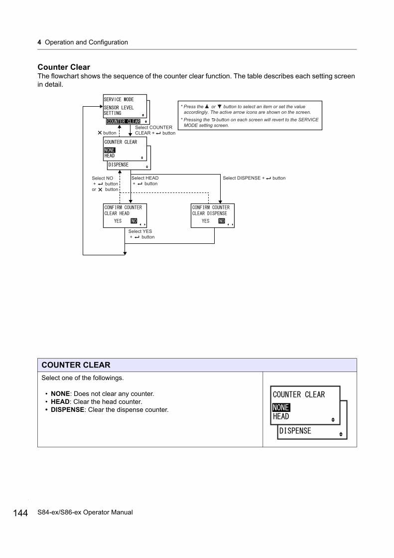
4 Operation and Configuration
144
Counter ClearThe flowchart shows the sequence of the counter clear function. The table describes each setting screen in detail.
COUNTER CLEAR
Select one of the followings.
• NONE: Does not clear any counter.• HEAD: Clear the head counter.• DISPENSE: Clear the dispense counter.
buttonSelect COUNTER CLEAR + button
* Press the or button to select an item or set the value accordingly. The active arrow icons are shown on the screen.
* Pressing the button on each screen will revert to the SERVICE MODE setting screen.
Select HEAD + button
Select DISPENSE + button
Select YES + button
Select NO + button or button
S84-ex/S86-ex Operator Manual

4 Operation and Configuration
CONFIRM COUNTER CLEAR HEAD
Select whether to clear the head counter or not.
• YES: Clear the head counter.• NO: Does not clear the head counter.
CONFIRM COUNTER CLEAR DISPENSE
Select whether to clear the dispense counter or not.
• YES: Clear the dispense counter.• NO: Does not clear the dispense counter.
145S84-ex/S86-ex Operator Manual
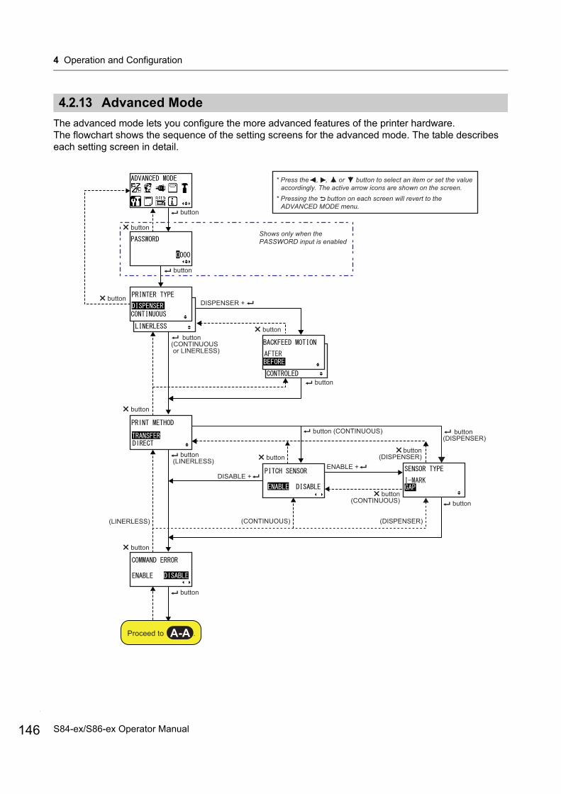
4 Operation and Configuration
146
4.2.13 Advanced Mode
The advanced mode lets you configure the more advanced features of the printer hardware.The flowchart shows the sequence of the setting screens for the advanced mode. The table describes each setting screen in detail.
Shows only when the PASSWORD input is enabled
* Press the , , or button to select an item or set the value accordingly. The active arrow icons are shown on the screen.
* Pressing the button on each screen will revert to the ADVANCED MODE menu.
button
button
button
DISPENSER +
button
button
button (CONTINUOUS)
button button
(DISPENSER) button (LINERLESS)
DISABLE +ENABLE +
button (CONTINUOUS) button
button
button (CONTINUOUS or LINERLESS)
button
(DISPENSER)
button (DISPENSER)
button
button
(CONTINUOUS)(LINERLESS)
Proceed to .A-A
S84-ex/S86-ex Operator Manual
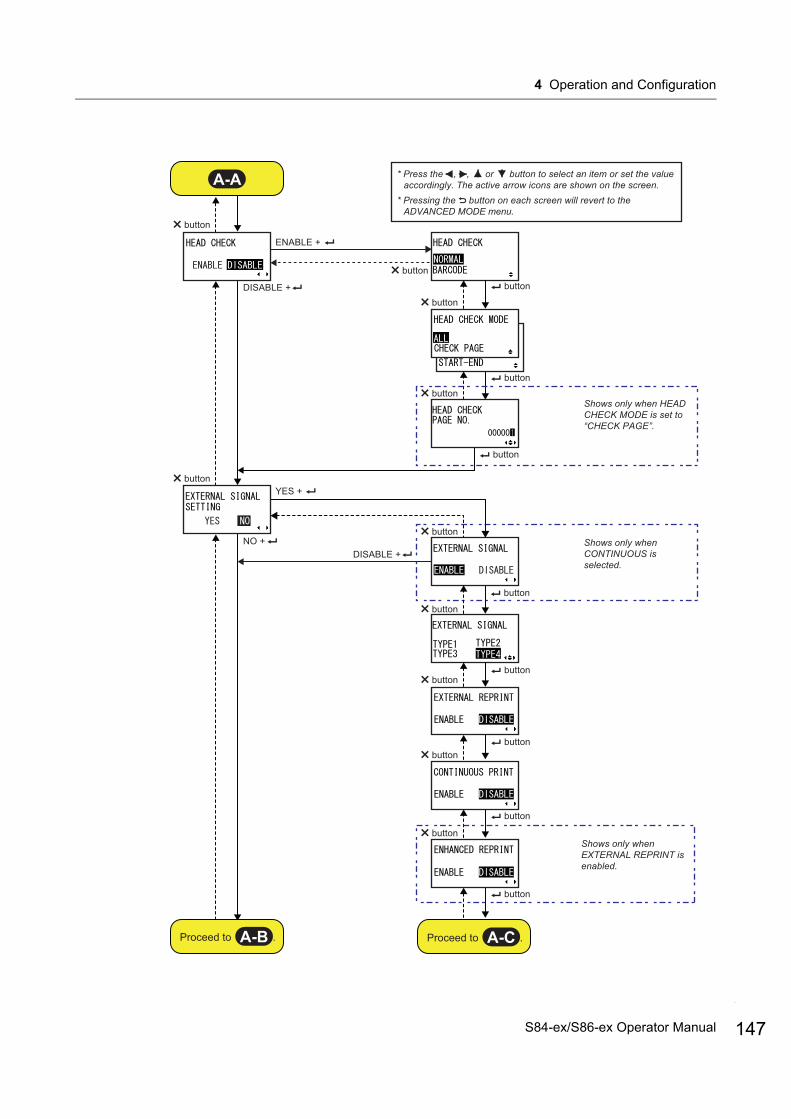
4 Operation and Configuration
Shows only when HEAD CHECK MODE is set to “CHECK PAGE”.
* Press the , , or button to select an item or set the value accordingly. The active arrow icons are shown on the screen.
* Pressing the button on each screen will revert to the ADVANCED MODE menu.
button
DISABLE +
ENABLE +
button
button
button
button
button
button
button
YES +
NO +button
Shows only when CONTINUOUS is selected.
button
buttonbutton
buttonbutton
button
button
DISABLE +
Shows only when EXTERNAL REPRINT is enabled.
button
A-A
Proceed to .A-CProceed to .A-B
button
147S84-ex/S86-ex Operator Manual
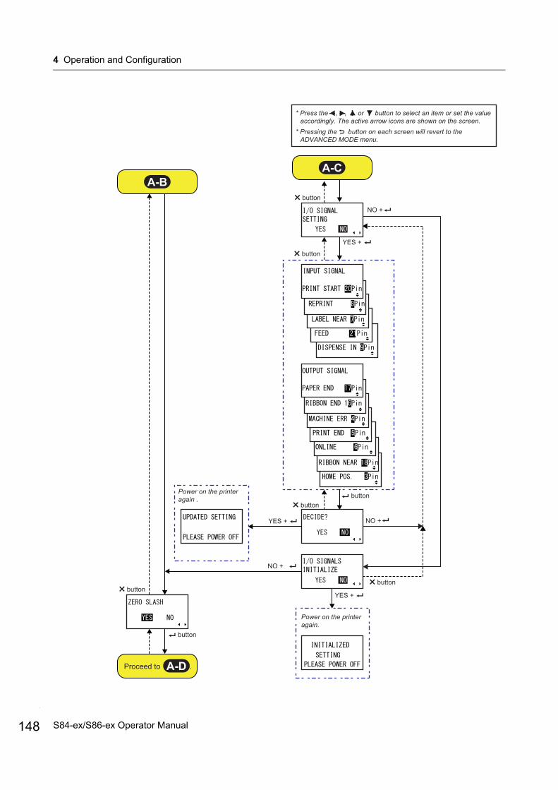
4 Operation and Configuration
148
button
button
button
buttonbutton
NO +
YES +
NO +YES +
NO +
button
Power on the printer again .
Power on the printer again.
YES +
button
* Press the , , or button to select an item or set the value accordingly. The active arrow icons are shown on the screen.
* Pressing the button on each screen will revert to the ADVANCED MODE menu.
A-BA-C
Proceed to .A-D
S84-ex/S86-ex Operator Manual

4 Operation and Configuration
* Press the , , or button to select an item or set the value accordingly. The active arrow icons are shown on the screen.
* Pressing the button on each screen will revert to the ADVANCED MODE menu.
button
YES +
NO +button
button
button
buttonbutton
button
button
button
button
button
button
Shows only when the head density is 12 dots/mm and legacy command support is selected.
Shows only when the calendar IC is installed
buttonbutton
button
button
button
button
A-D
Proceed to .A-E
button
button
YES +
NO +
149S84-ex/S86-ex Operator Manual
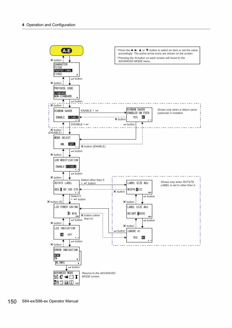
4 Operation and Configuration
150
* Press the , , or button to select an item or set the value accordingly. The active arrow icons are shown on the screen.
* Pressing the button on each screen will revert to the ADVANCED MODE menu.
button
button (0)
buttonbutton
button
button button
button
button
button button
button button
button
button
button
Returns to the ADVANCED MODE screen.
Shows only when ROTATE LABEL is set to other than 0.
A-E
buttonbutton
button
Select other than 0+ button
Select 0+ button
button (other than 0)
Shows only when a ribbon saver (optional) is installed.
button
button
button
DISABLE +
ENABLE +
button
button
button (ENABLE)
(DISABLE)
S84-ex/S86-ex Operator Manual
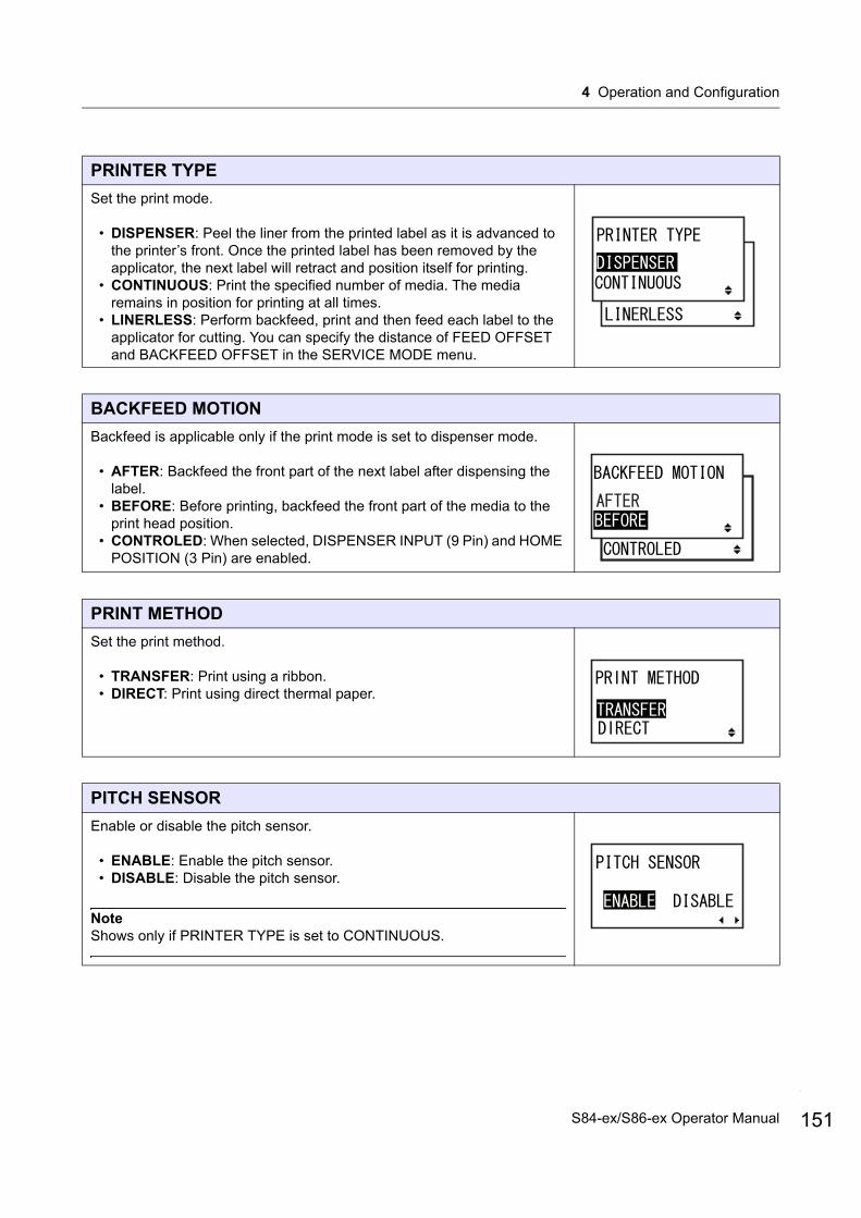
4 Operation and Configuration
PRINTER TYPE
Set the print mode.
• DISPENSER: Peel the liner from the printed label as it is advanced to the printer’s front. Once the printed label has been removed by the applicator, the next label will retract and position itself for printing.
• CONTINUOUS: Print the specified number of media. The media remains in position for printing at all times.
• LINERLESS: Perform backfeed, print and then feed each label to the applicator for cutting. You can specify the distance of FEED OFFSET and BACKFEED OFFSET in the SERVICE MODE menu.
BACKFEED MOTION
Backfeed is applicable only if the print mode is set to dispenser mode.
• AFTER: Backfeed the front part of the next label after dispensing the label.
• BEFORE: Before printing, backfeed the front part of the media to the print head position.
• CONTROLED: When selected, DISPENSER INPUT (9 Pin) and HOME POSITION (3 Pin) are enabled.
PRINT METHOD
Set the print method.
• TRANSFER: Print using a ribbon.• DIRECT: Print using direct thermal paper.
PITCH SENSOR
Enable or disable the pitch sensor.
• ENABLE: Enable the pitch sensor.• DISABLE: Disable the pitch sensor.
NoteShows only if PRINTER TYPE is set to CONTINUOUS.
151S84-ex/S86-ex Operator Manual
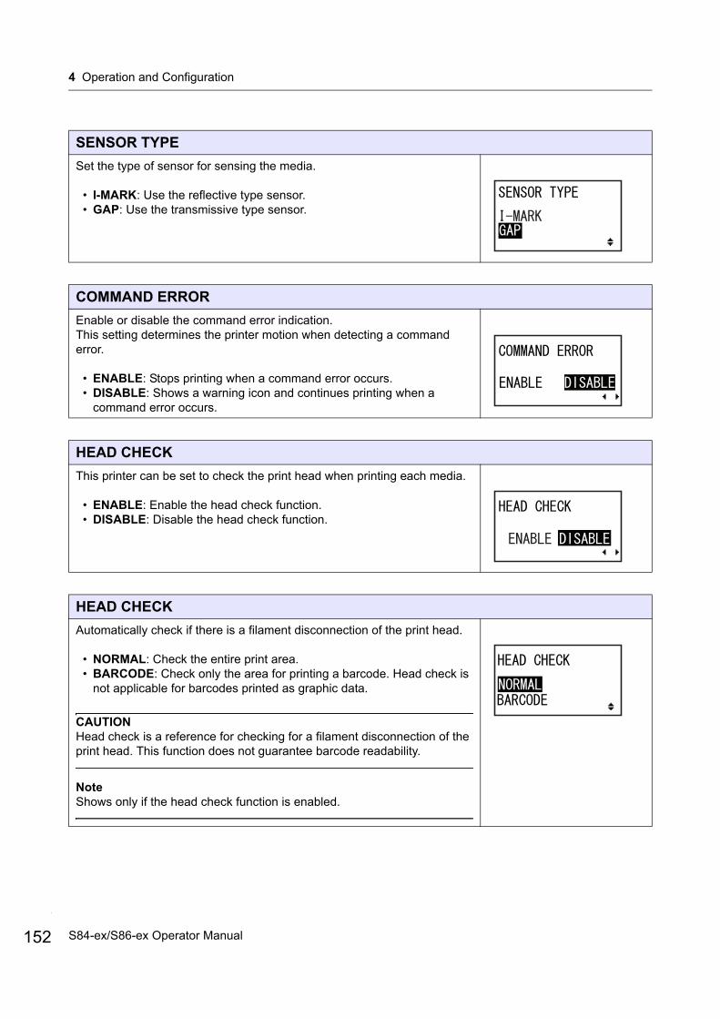
4 Operation and Configuration
152
SENSOR TYPE
Set the type of sensor for sensing the media.
• I-MARK: Use the reflective type sensor.• GAP: Use the transmissive type sensor.
COMMAND ERROR
Enable or disable the command error indication.This setting determines the printer motion when detecting a command error.
• ENABLE: Stops printing when a command error occurs.• DISABLE: Shows a warning icon and continues printing when a
command error occurs.
HEAD CHECK
This printer can be set to check the print head when printing each media.
• ENABLE: Enable the head check function.• DISABLE: Disable the head check function.
HEAD CHECK
Automatically check if there is a filament disconnection of the print head.
• NORMAL: Check the entire print area.• BARCODE: Check only the area for printing a barcode. Head check is
not applicable for barcodes printed as graphic data.
CAUTIONHead check is a reference for checking for a filament disconnection of the print head. This function does not guarantee barcode readability.
NoteShows only if the head check function is enabled.
S84-ex/S86-ex Operator Manual
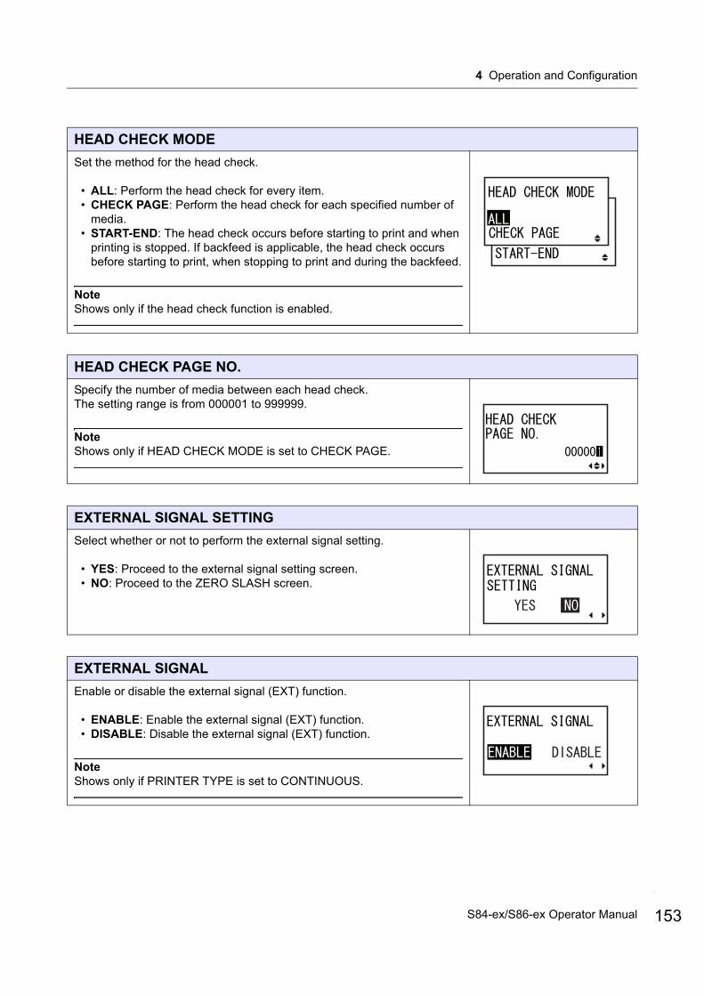
4 Operation and Configuration
HEAD CHECK MODE
Set the method for the head check.
• ALL: Perform the head check for every item.• CHECK PAGE: Perform the head check for each specified number of
media.• START-END: The head check occurs before starting to print and when
printing is stopped. If backfeed is applicable, the head check occurs before starting to print, when stopping to print and during the backfeed.
NoteShows only if the head check function is enabled.
HEAD CHECK PAGE NO.
Specify the number of media between each head check.The setting range is from 000001 to 999999.
NoteShows only if HEAD CHECK MODE is set to CHECK PAGE.
EXTERNAL SIGNAL SETTING
Select whether or not to perform the external signal setting.
• YES: Proceed to the external signal setting screen.• NO: Proceed to the ZERO SLASH screen.
EXTERNAL SIGNAL
Enable or disable the external signal (EXT) function.
• ENABLE: Enable the external signal (EXT) function.• DISABLE: Disable the external signal (EXT) function.
NoteShows only if PRINTER TYPE is set to CONTINUOUS.
153S84-ex/S86-ex Operator Manual

4 Operation and Configuration
154
EXTERNAL SIGNAL
Set the output signal type of the print end signal (PREND). The following options are available:
Note• Shows only if the external signal (EXT) function is enabled.• Refer to the Timing Chart of the EXT Input Signal for details.
EXTERNAL REPRINT
Set the reprint function by reprint signal (PRIN2) from the external signal.
• ENABLE: Enable the reprint when no print quantity is remaining.• DISABLE: Disable the reprint.
NoteThe printer will not reprint if a command error occurs.
CONTINUOUS PRINT
Set the reprint function by the print start signal (PRIN) from an external signal.
• ENABLE: Enable the continuous print when no print quantity is remaining.
• DISABLE: Disable the continuous print.
Type Operation Details
TYPE1 The print end signal (PREND) is High before label printing, and it becomes Low after print completion. The signal level becomes High after 20 ms.
TYPE2 The print end signal (PREND) is Low before label printing, and it becomes High after print completion. The signal level becomes Low after 20 ms.
TYPE3 The print end signal (PREND) is High before label printing, becomes Low from the start to the end of print, and becomes High again after print completion.
TYPE4 The print end signal (PREND) is Low before label printing, becomes High from the start to the end of print, and becomes Low again after print completion.
S84-ex/S86-ex Operator Manual
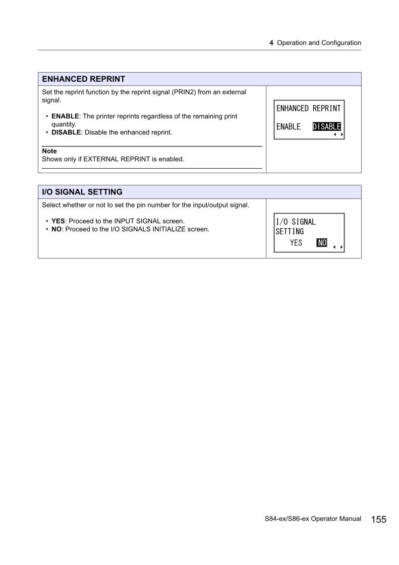
4 Operation and Configuration
ENHANCED REPRINT
Set the reprint function by the reprint signal (PRIN2) from an external signal.
• ENABLE: The printer reprints regardless of the remaining print quantity.
• DISABLE: Disable the enhanced reprint.
NoteShows only if EXTERNAL REPRINT is enabled.
I/O SIGNAL SETTING
Select whether or not to set the pin number for the input/output signal.
• YES: Proceed to the INPUT SIGNAL screen.• NO: Proceed to the I/O SIGNALS INITIALIZE screen.
155S84-ex/S86-ex Operator Manual

4 Operation and Configuration
156
INPUT SIGNAL/OUTPUT SIGNAL
Set the pin number for the input/output signal.The setting details are as follows:
Note• DISPENSE INPUT and HOME POSITION are available only if
CONTROLED is selected in BACKFEED MOTION.• For details, refer to Section 8.5 Input/Output Signal of the External
Signal.
Signal Name Input/Output
Default Pin No.
Overlapping
Available Pin No.
PRINT START Input 20 Not Allowed
Can be set to 8 or 20.
REPRINT Input 8 Not Allowed
LABEL NEAR END Input 7 Not Allowed
Can be set to 7 or 21.“-”: Function is disabled.
FEED Input 21 Not Allowed
DISPENSE INPUT Input 9 Not Allowed
Can be set to 7, 9 or 21.“-”: Printer
operates with PRIN START as a trigger.
PAPER END Output 17 Allowed Can be set to 4, 5, 6, 16, 17 or 18.“-”: No output
RIBBON END Output 16 Allowed
MACHINE ERROR Output 4 Allowed
PRINT END Output 5 Not Allowed
ONLINE Output 6 Allowed
RIBBON NEAR END Output 18 Allowed
HOME POSITION Output 3 Not Allowed
Can be set to 3, 4, 5, 6, 16, 17 or 18.“-”: No output
S84-ex/S86-ex Operator Manual
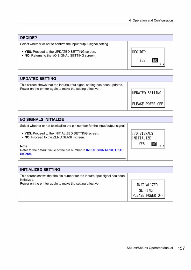
4 Operation and Configuration
DECIDE?
Select whether or not to confirm the input/output signal setting.
• YES: Proceed to the UPDATED SETTING screen.• NO: Returns to the I/O SIGNAL SETTING screen.
UPDATED SETTING
This screen shows that the input/output signal setting has been updated. Power on the printer again to make the setting effective.
I/O SIGNALS INITIALIZE
Select whether or not to initialize the pin number for the input/output signal.
• YES: Proceed to the INITIALIZED SETTING screen.• NO: Proceed to the ZERO SLASH screen.
NoteRefer to the default value of the pin number in INPUT SIGNAL/OUTPUT SIGNAL.
INITIALIZED SETTING
This screen shows that the pin number for the input/output signal has been initialized. Power on the printer again to make the setting effective.
157S84-ex/S86-ex Operator Manual
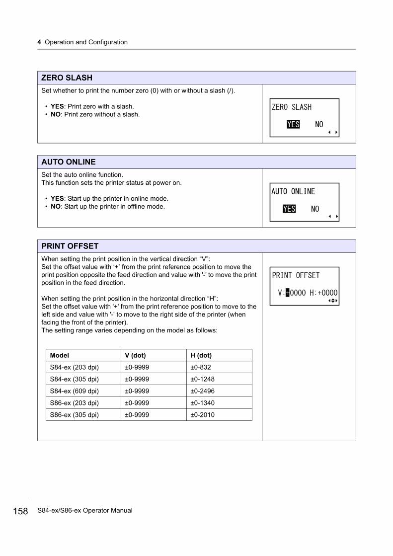
4 Operation and Configuration
158
ZERO SLASH
Set whether to print the number zero (0) with or without a slash (/).
• YES: Print zero with a slash.• NO: Print zero without a slash.
AUTO ONLINE
Set the auto online function.This function sets the printer status at power on.
• YES: Start up the printer in online mode.• NO: Start up the printer in offline mode.
PRINT OFFSET
When setting the print position in the vertical direction “V”:Set the offset value with ‘+’ from the print reference position to move the print position opposite the feed direction and value with '-' to move the print position in the feed direction.
When setting the print position in the horizontal direction “H”:Set the offset value with '+' from the print reference position to move to the left side and value with '-' to move to the right side of the printer (when facing the front of the printer).The setting range varies depending on the model as follows:
Model V (dot) H (dot)
S84-ex (203 dpi) ±0-9999 ±0-832
S84-ex (305 dpi) ±0-9999 ±0-1248
S84-ex (609 dpi) ±0-9999 ±0-2496
S86-ex (203 dpi) ±0-9999 ±0-1340
S86-ex (305 dpi) ±0-9999 ±0-2010
S84-ex/S86-ex Operator Manual
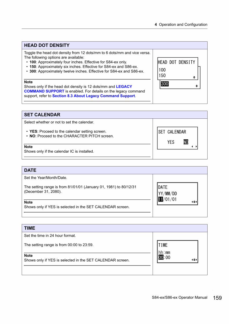
4 Operation and Configuration
HEAD DOT DENSITY
Toggle the head dot density from 12 dots/mm to 6 dots/mm and vice versa.The following options are available:
• 100: Approximately four inches. Effective for S84-ex only.• 150: Approximately six inches. Effective for S84-ex and S86-ex.• 300: Approximately twelve inches. Effective for S84-ex and S86-ex.
NoteShows only if the head dot density is 12 dots/mm and LEGACY COMMAND SUPPORT is enabled. For details on the legacy command support, refer to Section 8.3 About Legacy Command Support.
SET CALENDAR
Select whether or not to set the calendar.
• YES: Proceed to the calendar setting screen.• NO: Proceed to the CHARACTER PITCH screen.
NoteShows only if the calendar IC is installed.
DATE
Set the Year/Month/Date.
The setting range is from 81/01/01 (January 01, 1981) to 80/12/31 (December 31, 2080).
NoteShows only if YES is selected in the SET CALENDAR screen.
TIME
Set the time in 24 hour format.
The setting range is from 00:00 to 23:59.
NoteShows only if YES is selected in the SET CALENDAR screen.
159S84-ex/S86-ex Operator Manual
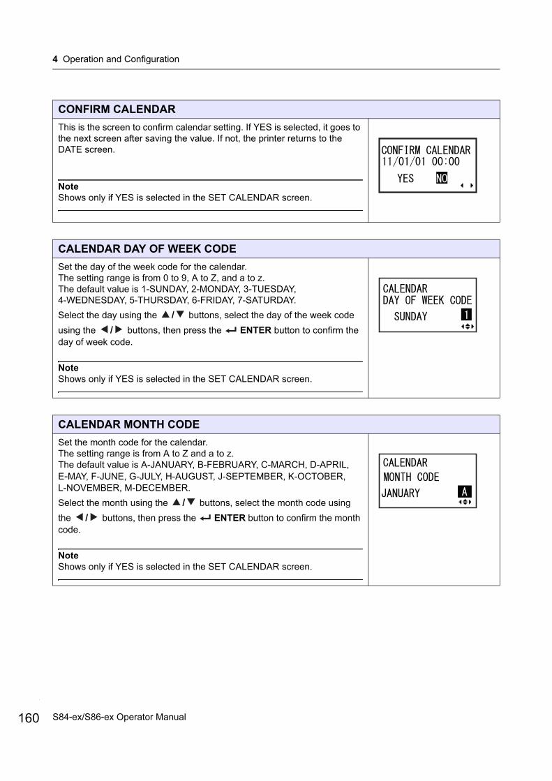
4 Operation and Configuration
160
CONFIRM CALENDAR
This is the screen to confirm calendar setting. If YES is selected, it goes to the next screen after saving the value. If not, the printer returns to the DATE screen.
NoteShows only if YES is selected in the SET CALENDAR screen.
CALENDAR DAY OF WEEK CODE
Set the day of the week code for the calendar.The setting range is from 0 to 9, A to Z, and a to z. The default value is 1-SUNDAY, 2-MONDAY, 3-TUESDAY, 4-WEDNESDAY, 5-THURSDAY, 6-FRIDAY, 7-SATURDAY.
Select the day using the / buttons, select the day of the week code
using the / buttons, then press the ENTER button to confirm the day of week code.
NoteShows only if YES is selected in the SET CALENDAR screen.
CALENDAR MONTH CODE
Set the month code for the calendar.The setting range is from A to Z and a to z.The default value is A-JANUARY, B-FEBRUARY, C-MARCH, D-APRIL, E-MAY, F-JUNE, G-JULY, H-AUGUST, J-SEPTEMBER, K-OCTOBER, L-NOVEMBER, M-DECEMBER.
Select the month using the / buttons, select the month code using
the / buttons, then press the ENTER button to confirm the month code.
NoteShows only if YES is selected in the SET CALENDAR screen.
S84-ex/S86-ex Operator Manual
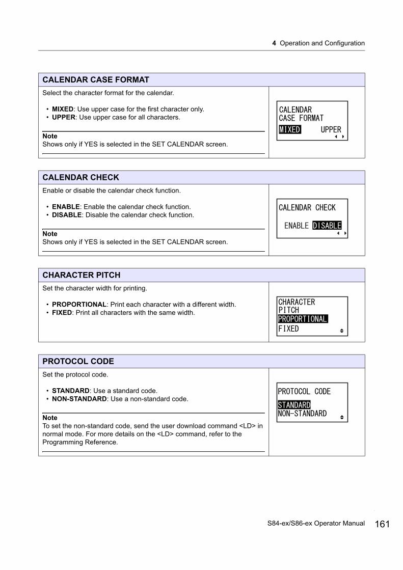
4 Operation and Configuration
CALENDAR CASE FORMAT
Select the character format for the calendar.
• MIXED: Use upper case for the first character only.• UPPER: Use upper case for all characters.
NoteShows only if YES is selected in the SET CALENDAR screen.
CALENDAR CHECK
Enable or disable the calendar check function.
• ENABLE: Enable the calendar check function.• DISABLE: Disable the calendar check function.
NoteShows only if YES is selected in the SET CALENDAR screen.
CHARACTER PITCH
Set the character width for printing.
• PROPORTIONAL: Print each character with a different width.• FIXED: Print all characters with the same width.
PROTOCOL CODE
Set the protocol code.
• STANDARD: Use a standard code.• NON-STANDARD: Use a non-standard code.
NoteTo set the non-standard code, send the user download command <LD> in normal mode. For more details on the <LD> command, refer to the Programming Reference.
161S84-ex/S86-ex Operator Manual

4 Operation and Configuration
162
RIBBON SAVER
Enable or disable the ribbon saver function.
• ENABLE: Use the ribbon saver.• DISABLE: Do not use the ribbon saver.
NoteShows only if the optional ribbon saver is installed. The optional ribbon saver is only available for the S84-ex printer. For details on the ribbon saver function, refer to Section 8.10 Optional Ribbon Saver.
RIBBON SAVER ENABLED ON FEED
Enable or disable the ribbon saver function during feed.
• YES: Use the ribbon saver during feed.• NO: Use the ribbon saver but not during feed.
NoteShows only if the optional ribbon saver is installed and enabled. The optional ribbon saver is only available for the S84-ex printer. For details on the ribbon saver function, refer to Section 8.10 Optional Ribbon Saver.
MODE SELECT
Set the communication command mode for analysis.
• XML: Use for supporting Oracle and SAP mode.• SBPL: Use SBPL (SATO Barcode Printer Language) for the printer
commands.
NoteThe setting will be effective only if you power on the printer again.
JOB MODIFICATION
Set the job modification function.Use the job modification command <#J> to specify the strings before and after conversion.
• ENABLE: Enable the job modification function.• DISABLE: Disable the job modification function.
S84-ex/S86-ex Operator Manual
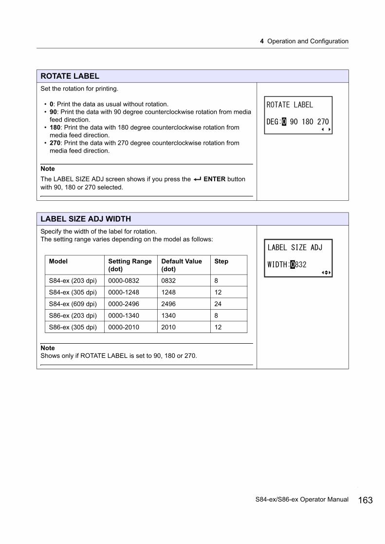
4 Operation and Configuration
ROTATE LABEL
Set the rotation for printing.
• 0: Print the data as usual without rotation.• 90: Print the data with 90 degree counterclockwise rotation from media
feed direction.• 180: Print the data with 180 degree counterclockwise rotation from
media feed direction.• 270: Print the data with 270 degree counterclockwise rotation from
media feed direction.
Note
The LABEL SIZE ADJ screen shows if you press the ENTER button with 90, 180 or 270 selected.
LABEL SIZE ADJ WIDTH
Specify the width of the label for rotation.The setting range varies depending on the model as follows:
NoteShows only if ROTATE LABEL is set to 90, 180 or 270.
Model Setting Range (dot)
Default Value (dot)
Step
S84-ex (203 dpi) 0000-0832 0832 8
S84-ex (305 dpi) 0000-1248 1248 12
S84-ex (609 dpi) 0000-2496 2496 24
S86-ex (203 dpi) 0000-1340 1340 8
S86-ex (305 dpi) 0000-2010 2010 12
163S84-ex/S86-ex Operator Manual

4 Operation and Configuration
164
LABEL SIZE ADJ HEIGHT
Specify the height of the label for rotation.The setting range varies depending on the model as follows:
NoteShows only if ROTATE LABEL is set to 90, 180 or 270.
IGNORE A1
Select whether or not to ignore the <A1> command.<A1> command is to set the media size.Refer to the Programming Reference for details of the command.
• YES: Ignore the <A1> command.• NO: Proceed with the <A1> command.
NoteShows only if ROTATE LABEL is set to 90, 180 or 270.
LCD POWER SAVING
Specify a period of time to light off the LCD backlight when the printer is not operated.The setting range is from 00 to 15 minutes.
NoteThis function is disabled if set to 00; the LCD backlight will remain on. For details, refer to Section 8.4 LCD Power Saving Mode.
Model Setting Range (dot)
Default Value (dot)
S84-ex (203 dpi) 00000-20000 20000
S84-ex (305 dpi) 00000-18000 18000
S84-ex (609 dpi) 00000-09600 09600
S86-ex (203 dpi) 00000-09992 09992
S86-ex (305 dpi) 00000-14988 14988
S84-ex/S86-ex Operator Manual
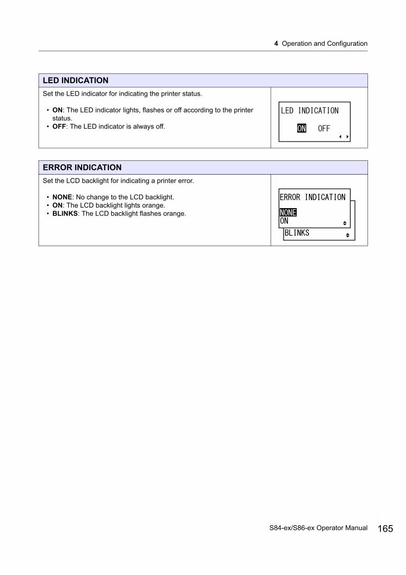
4 Operation and Configuration
LED INDICATION
Set the LED indicator for indicating the printer status.
• ON: The LED indicator lights, flashes or off according to the printer status.
• OFF: The LED indicator is always off.
ERROR INDICATION
Set the LCD backlight for indicating a printer error.
• NONE: No change to the LCD backlight.• ON: The LCD backlight lights orange.• BLINKS: The LCD backlight flashes orange.
165S84-ex/S86-ex Operator Manual
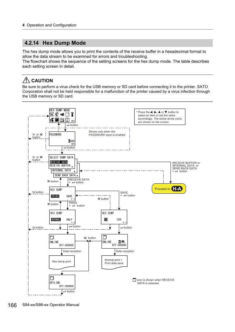
4 Operation and Configuration
166
4.2.14 Hex Dump Mode
The hex dump mode allows you to print the contents of the receive buffer in a hexadecimal format to allow the data stream to be examined for errors and troubleshooting.The flowchart shows the sequence of the setting screens for the hex dump mode. The table describes each setting screen in detail.
CAUTIONBe sure to perform a virus check for the USB memory or SD card before connecting it to the printer. SATO Corporation shall not be held responsible for a malfunction of the printer caused by a virus infection through the USB memory or SD card.
Hex dump print
RECEIVE BUFFER or INTERNAL DATA orSEND BACK DATA+ button
Shows only when the PASSWORD input is enabled
Normal print + Print data save
* Press the , , or button to select an item or set the value accordingly. The active arrow icons are shown on the screen.
Data reception
icon is shown when RECEIVE DATA is selected.
button
or button
or button
button
RECEIVE DATA+ button
button button
button
button
Proceed to .H-A
button
button
PRINT+ button
button
button
SAVE+ button
button
Data reception
S84-ex/S86-ex Operator Manual
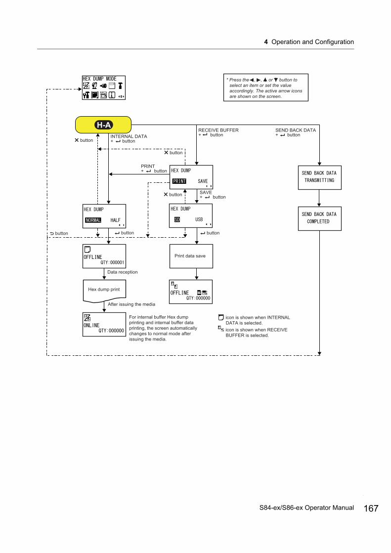
4 Operation and Configuration
Hex dump print
For internal buffer Hex dump printing and internal buffer data printing, the screen automatically changes to normal mode after issuing the media.
* Press the , , or button to select an item or set the value accordingly. The active arrow icons are shown on the screen.
After issuing the media
icon is shown when INTERNAL DATA is selected.icon is shown when RECEIVE BUFFER is selected.
RECEIVE BUFFER + buttonINTERNAL DATA
+ button
button button
SEND BACK DATA+ button
H-A
button SAVE+ button
button
button
button
PRINT+ button
Data reception
Print data save
167S84-ex/S86-ex Operator Manual
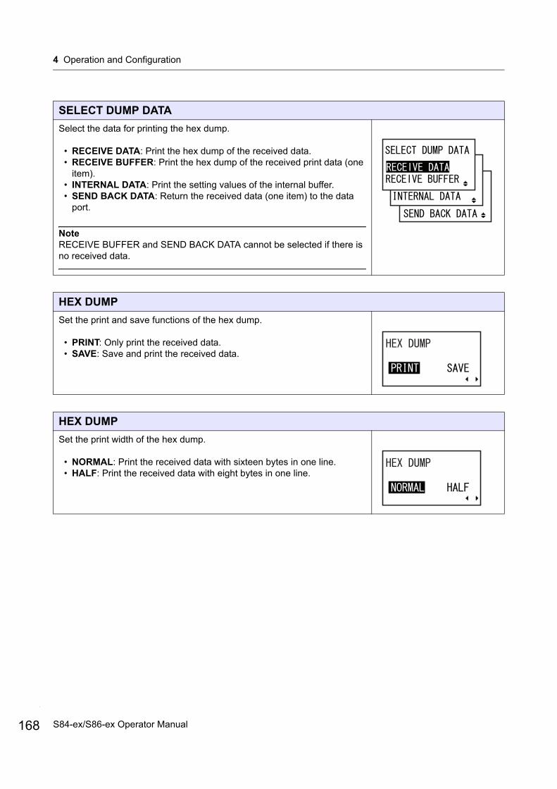
4 Operation and Configuration
168
SELECT DUMP DATA
Select the data for printing the hex dump.
• RECEIVE DATA: Print the hex dump of the received data.• RECEIVE BUFFER: Print the hex dump of the received print data (one
item).• INTERNAL DATA: Print the setting values of the internal buffer.• SEND BACK DATA: Return the received data (one item) to the data
port.
NoteRECEIVE BUFFER and SEND BACK DATA cannot be selected if there is no received data.
HEX DUMP
Set the print and save functions of the hex dump.
• PRINT: Only print the received data.• SAVE: Save and print the received data.
HEX DUMP
Set the print width of the hex dump.
• NORMAL: Print the received data with sixteen bytes in one line.• HALF: Print the received data with eight bytes in one line.
S84-ex/S86-ex Operator Manual
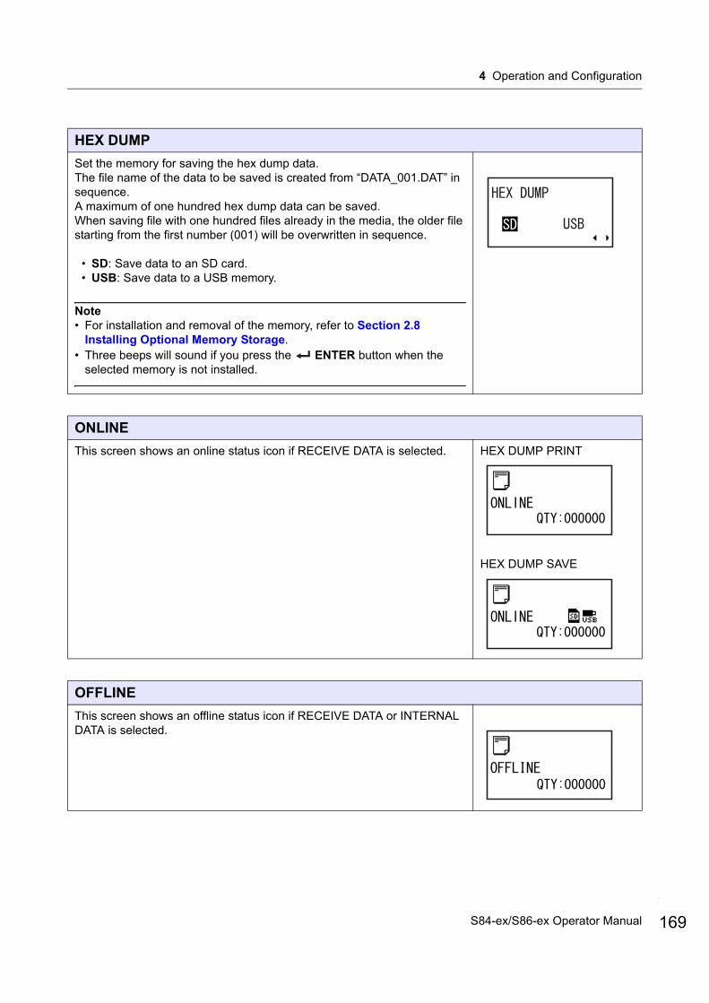
4 Operation and Configuration
HEX DUMP
Set the memory for saving the hex dump data.The file name of the data to be saved is created from “DATA_001.DAT” in sequence.A maximum of one hundred hex dump data can be saved.When saving file with one hundred files already in the media, the older file starting from the first number (001) will be overwritten in sequence.
• SD: Save data to an SD card.• USB: Save data to a USB memory.
Note• For installation and removal of the memory, refer to Section 2.8
Installing Optional Memory Storage.• Three beeps will sound if you press the ENTER button when the
selected memory is not installed.
ONLINE
This screen shows an online status icon if RECEIVE DATA is selected. HEX DUMP PRINT
HEX DUMP SAVE
OFFLINE
This screen shows an offline status icon if RECEIVE DATA or INTERNAL DATA is selected.
169S84-ex/S86-ex Operator Manual
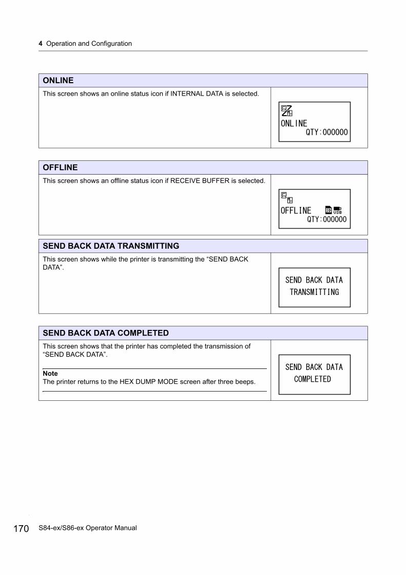
4 Operation and Configuration
170
ONLINE
This screen shows an online status icon if INTERNAL DATA is selected.
OFFLINE
This screen shows an offline status icon if RECEIVE BUFFER is selected.
SEND BACK DATA TRANSMITTING
This screen shows while the printer is transmitting the “SEND BACK DATA”.
SEND BACK DATA COMPLETED
This screen shows that the printer has completed the transmission of “SEND BACK DATA”.
NoteThe printer returns to the HEX DUMP MODE screen after three beeps.
S84-ex/S86-ex Operator Manual
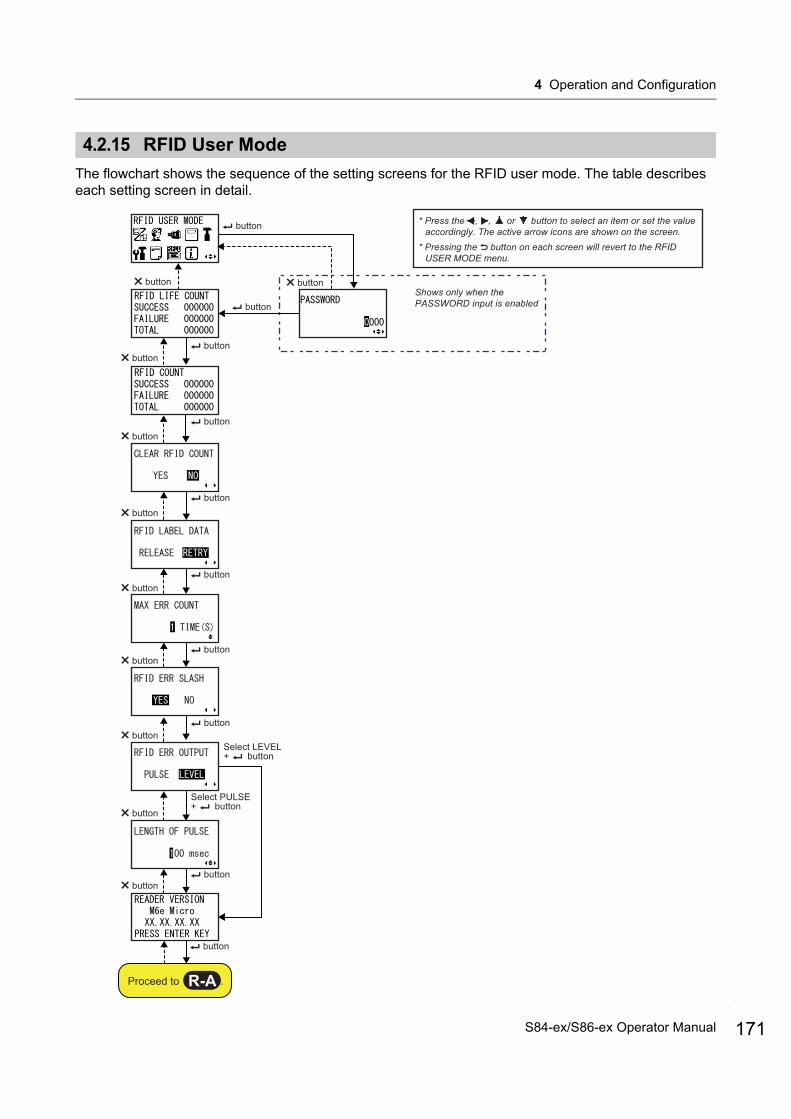
4 Operation and Configuration
4.2.15 RFID User Mode
The flowchart shows the sequence of the setting screens for the RFID user mode. The table describes each setting screen in detail.
* Press the , , or button to select an item or set the value accordingly. The active arrow icons are shown on the screen.
* Pressing the button on each screen will revert to the RFID USER MODE menu.
button
buttonbutton
button
button
button button
button button
button
button
button button
buttonbutton
Shows only when the PASSWORD input is enabled
button
button
buttonbutton
button
Proceed to .R-A
Select LEVEL + button
Select PULSE + button
171S84-ex/S86-ex Operator Manual
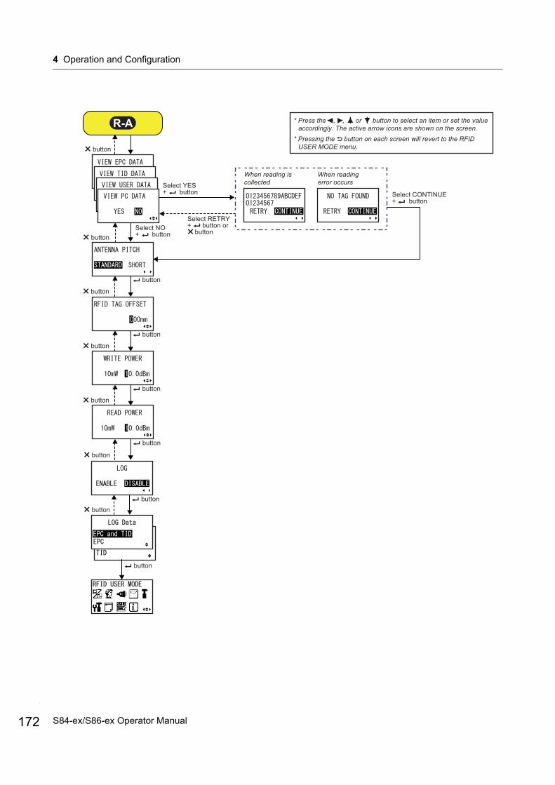
4 Operation and Configuration
172
* Press the , , or button to select an item or set the value accordingly. The active arrow icons are shown on the screen.
* Pressing the button on each screen will revert to the RFID USER MODE menu.
button
button button
button
button
R-A
button
Select YES + button
When reading error occurs
When reading is collected
button
button
button
button
button
button
button
Select CONTINUE + button
Select RETRY + button or buttonSelect NO
+ button
S84-ex/S86-ex Operator Manual
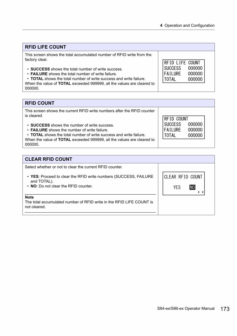
4 Operation and Configuration
RFID LIFE COUNT
This screen shows the total accumulated number of RFID write from the factory clear.
• SUCCESS shows the total number of write success.• FAILURE shows the total number of write failure.• TOTAL shows the total number of write success and write failure.
When the value of TOTAL exceeded 999999, all the values are cleared to 000000.
RFID COUNT
This screen shows the current RFID write numbers after the RFID counter is cleared.
• SUCCESS shows the number of write success.• FAILURE shows the number of write failure.• TOTAL shows the total number of write success and write failure.
When the value of TOTAL exceeded 999999, all the values are cleared to 000000.
CLEAR RFID COUNT
Select whether or not to clear the current RFID counter.
• YES: Proceed to clear the RFID write numbers (SUCCESS, FAILURE and TOTAL).
• NO: Do not clear the RFID counter.
NoteThe total accumulated number of RFID write in the RFID LIFE COUNT is not cleared.
173S84-ex/S86-ex Operator Manual
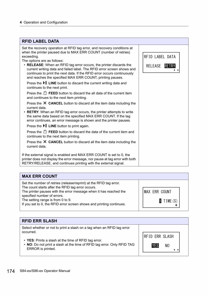
4 Operation and Configuration
174
RFID LABEL DATA
Set the recovery operation at RFID tag error, and recovery conditions at when the printer paused due to MAX ERR COUNT (number of retries) exceeding.The options are as follows:
• RELEASE: When an RFID tag error occurs, the printer discards the current writing data and failed label. The RFID error screen shows and continues to print the next data. If the RFID error occurs continuously and reaches the specified MAX ERR COUNT, printing pauses.
Press the LINE button to discard the current writing data and continues to the next print.
Press the FEED button to discard the all data of the current item and continues to the next item printing.
Press the CANCEL button to discard all the item data including the current data.
• RETRY: When an RFID tag error occurs, the printer attempts to write the same data based on the specified MAX ERR COUNT. If the tag error continues, an error message is shown and the printer pauses.
Press the LINE button to print again.
Press the FEED button to discard the data of the current item and continues to the next item printing.
Press the CANCEL button to discard all the item data including the current data.
If the external signal is enabled and MAX ERR COUNT is set to 0, the printer does not display the error message, nor pause at tag error with both RETRY/RELEASE, and continues printing with the external signal.
MAX ERR COUNT
Set the number of retries (release/reprint) at the RFID tag error.The count starts after the RFID tag error occurs.The printer pauses with the error message when it has reached the specified number of errors.The setting range is from 0 to 9. If you set to 0, the RFID error screen shows and printing continues.
RFID ERR SLASH
Select whether or not to print a slash on a tag when an RFID tag error occurred.
• YES: Prints a slash at the time of RFID tag error.• NO: Do not print a slash at the time of RFID tag error. Only RFID TAG
ERROR is printed.
S84-ex/S86-ex Operator Manual
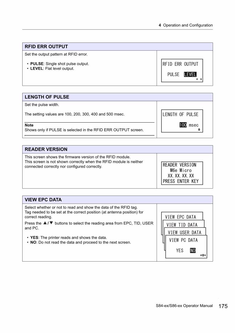
4 Operation and Configuration
RFID ERR OUTPUT
Set the output pattern at RFID error.
• PULSE: Single shot pulse output.• LEVEL: Flat level output.
LENGTH OF PULSE
Set the pulse width.
The setting values are 100, 200, 300, 400 and 500 msec.
NoteShows only if PULSE is selected in the RFID ERR OUTPUT screen.
READER VERSION
This screen shows the firmware version of the RFID module.This screen is not shown correctly when the RFID module is neither connected correctly nor configured correctly.
VIEW EPC DATA
Select whether or not to read and show the data of the RFID tag.Tag needed to be set at the correct position (at antenna position) for correct reading.
Press the / buttons to select the reading area from EPC, TID, USER and PC.
• YES: The printer reads and shows the data.• NO: Do not read the data and proceed to the next screen.
175S84-ex/S86-ex Operator Manual
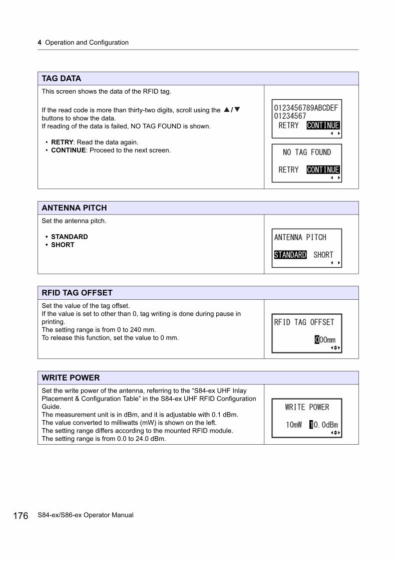
4 Operation and Configuration
176
TAG DATA
This screen shows the data of the RFID tag.
If the read code is more than thirty-two digits, scroll using the / buttons to show the data.If reading of the data is failed, NO TAG FOUND is shown.
• RETRY: Read the data again.• CONTINUE: Proceed to the next screen.
ANTENNA PITCH
Set the antenna pitch.
• STANDARD• SHORT
RFID TAG OFFSET
Set the value of the tag offset.If the value is set to other than 0, tag writing is done during pause in printing.The setting range is from 0 to 240 mm.To release this function, set the value to 0 mm.
WRITE POWER
Set the write power of the antenna, referring to the “S84-ex UHF Inlay Placement & Configuration Table” in the S84-ex UHF RFID Configuration Guide.The measurement unit is in dBm, and it is adjustable with 0.1 dBm.The value converted to milliwatts (mW) is shown on the left.The setting range differs according to the mounted RFID module.The setting range is from 0.0 to 24.0 dBm.
S84-ex/S86-ex Operator Manual

4 Operation and Configuration
READ POWER
Set the read power of the antenna, referring to the “S84-ex UHF Inlay Placement & Configuration Table” in the S84-ex UHF RFID Configuration Guide.The measurement unit is in dBm, and it is adjustable with 0.1 dBm.The value converted to milliwatts (mW) is shown on the left.The setting range differs according to the mounted RFID module.The setting range is from 0.0 to 24.0 dBm.
LOG
Enable or disable the log function to record the RFID data.The log data can record up to100 tags of information.
• ENABLE: Enable the log function to record the RFID data.• DISABLE: Disable the log function to record the RFID data.
LOG Data
Set the data to be recorded in the log when LOG is enabled.
• EPC and TID: Store the EPC and TID data.• EPC: Store the EPC data.• TID: Store the TID data.
177S84-ex/S86-ex Operator Manual
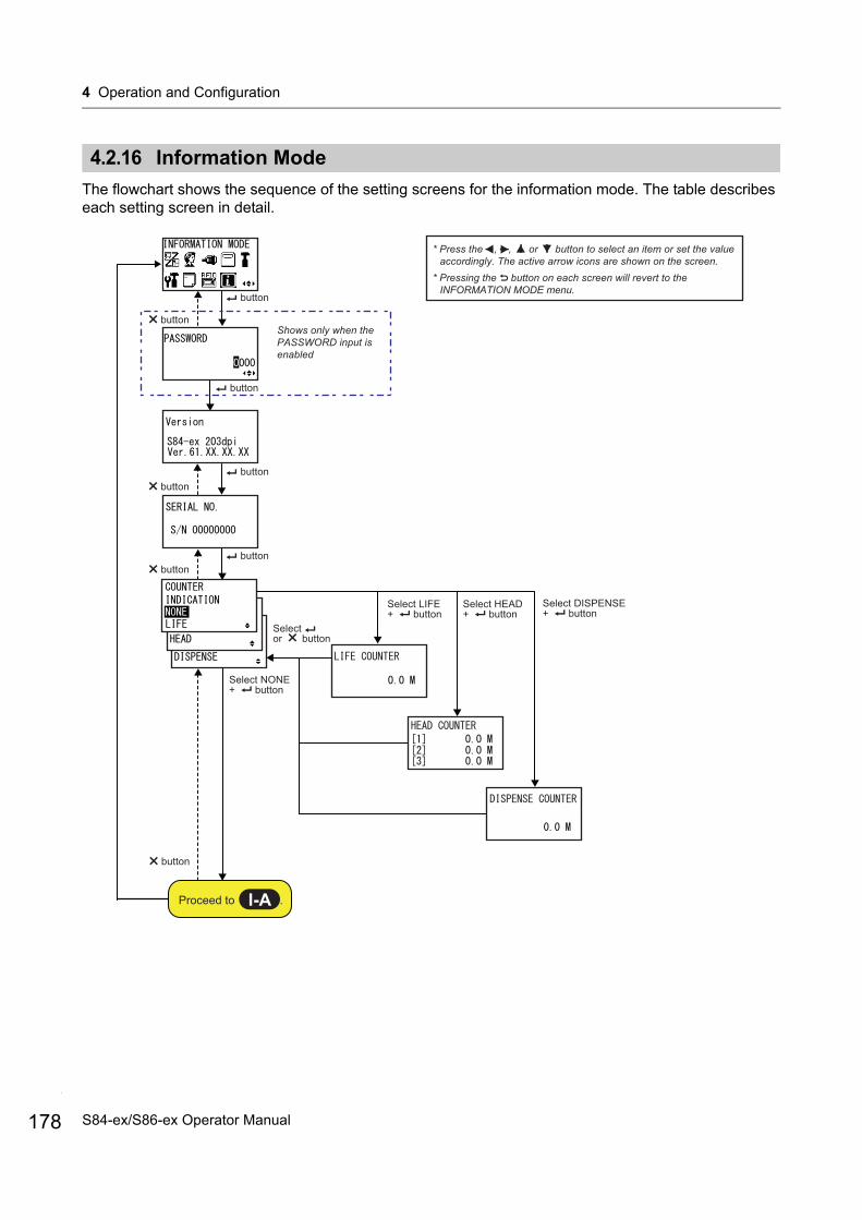
4 Operation and Configuration
178
4.2.16 Information Mode
The flowchart shows the sequence of the setting screens for the information mode. The table describes each setting screen in detail.
* Press the , , or button to select an item or set the value accordingly. The active arrow icons are shown on the screen.
* Pressing the button on each screen will revert to the INFORMATION MODE menu.
button
button
button
button button
Shows only when the PASSWORD input is enabled
button
Proceed to .I-A
button
Select NONE + button
Select LIFE + button
Select HEAD + button
button
Select DISPENSE + button
Select or button
S84-ex/S86-ex Operator Manual

4 Operation and Configuration
Version
Shows the model name and firmware version of this printer.
SERIAL NO.
Shows the serial number of the control board in this printer.
* Press the , , or button to select an item or set the value accordingly. The active arrow icons are shown on the screen.
* Pressing the button on each screen will revert to the INFORMATION MODE menu.
button button
button
button
button
Shows as “---.---.---.---” if an IP address is not acquired from the DHCP setting.
button
button
button
button
button
button
button
button
button
button
buttonbutton
Shows only when a wireless LAN unit is installed.
Shows with the following conditions: Manual setting: DISABLE Auto settings (not confirmed): -----Auto settings (confirmed): IEEE1284/RS-232C/LAN/USB/WLAN/Bluetooth
I-A
179S84-ex/S86-ex Operator Manual
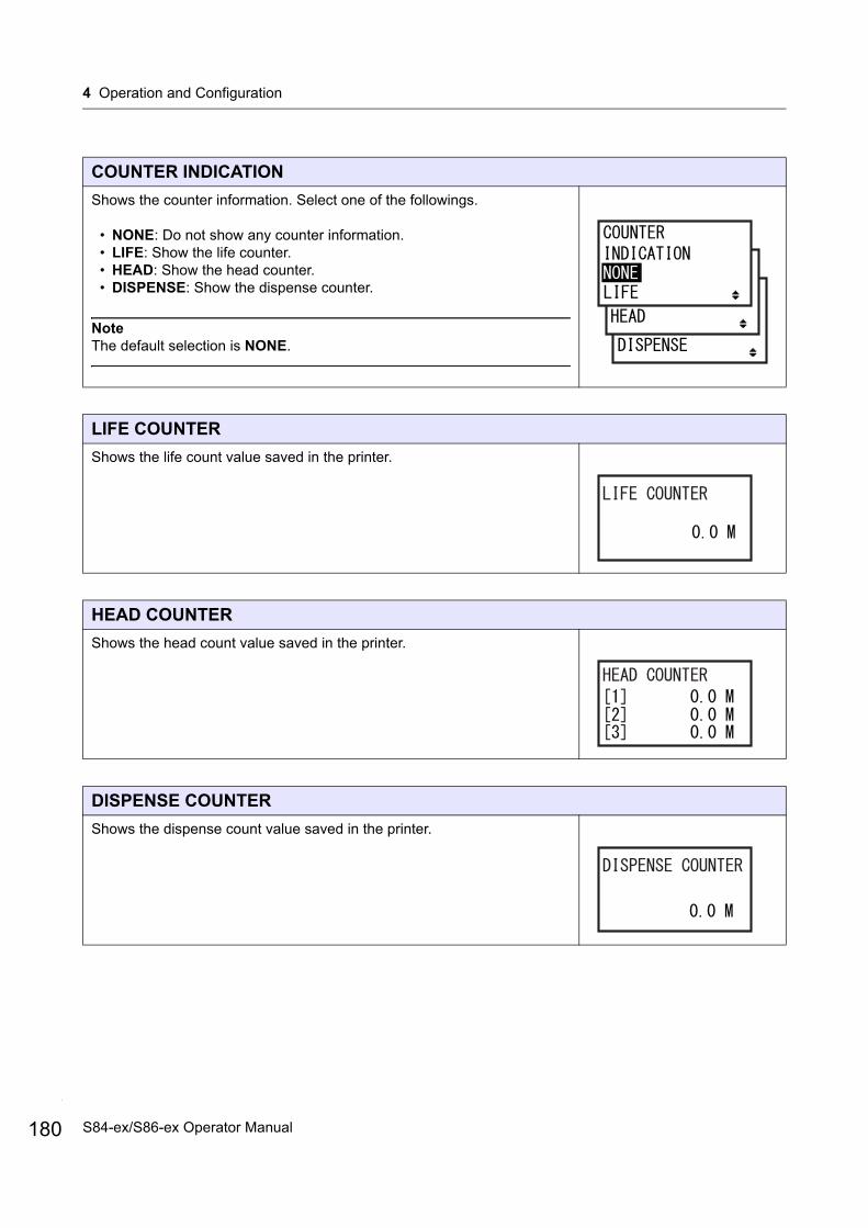
4 Operation and Configuration
180
COUNTER INDICATION
Shows the counter information. Select one of the followings.
• NONE: Do not show any counter information.• LIFE: Show the life counter.• HEAD: Show the head counter.• DISPENSE: Show the dispense counter.
NoteThe default selection is NONE.
LIFE COUNTER
Shows the life count value saved in the printer.
HEAD COUNTER
Shows the head count value saved in the printer.
DISPENSE COUNTER
Shows the dispense count value saved in the printer.
S84-ex/S86-ex Operator Manual
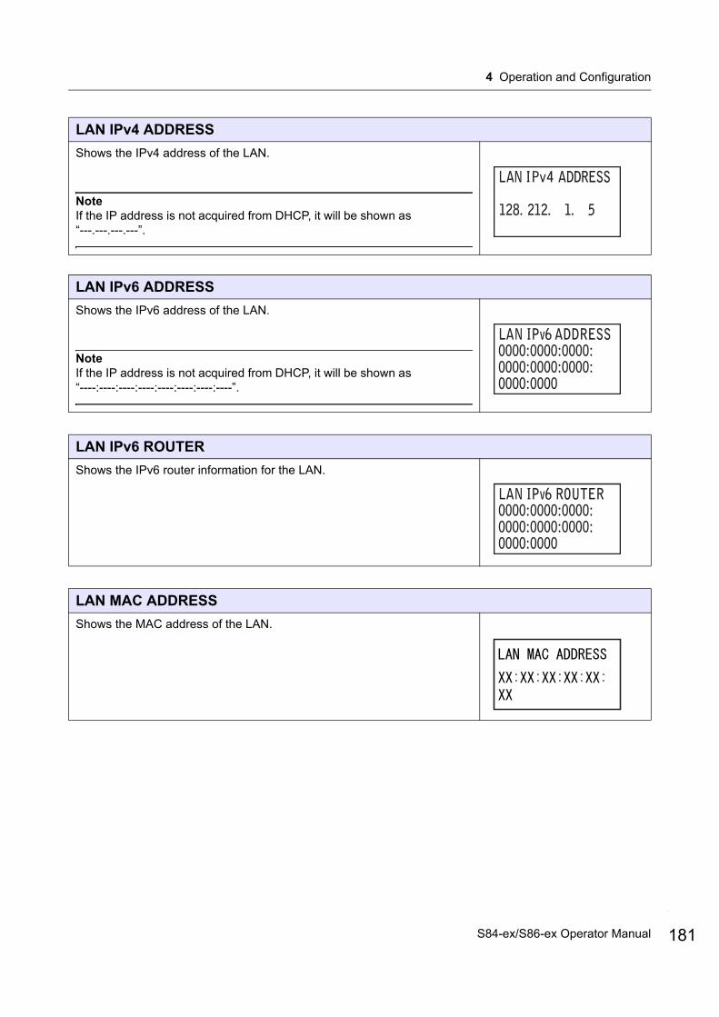
4 Operation and Configuration
LAN IPv4 ADDRESS
Shows the IPv4 address of the LAN.
NoteIf the IP address is not acquired from DHCP, it will be shown as “---.---.---.---”.
LAN IPv6 ADDRESS
Shows the IPv6 address of the LAN.
NoteIf the IP address is not acquired from DHCP, it will be shown as “----:----:----:----:----:----:----:----”.
LAN IPv6 ROUTER
Shows the IPv6 router information for the LAN.
LAN MAC ADDRESS
Shows the MAC address of the LAN.
181S84-ex/S86-ex Operator Manual
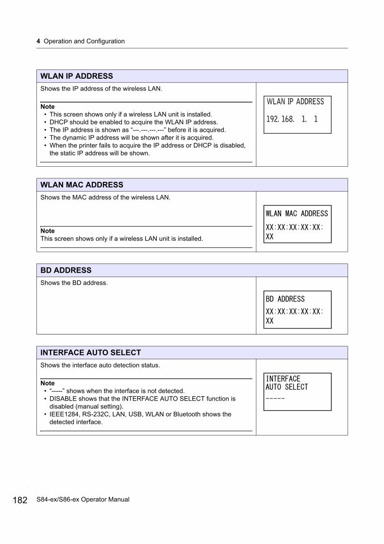
4 Operation and Configuration
182
WLAN IP ADDRESS
Shows the IP address of the wireless LAN.
Note• This screen shows only if a wireless LAN unit is installed.• DHCP should be enabled to acquire the WLAN IP address.• The IP address is shown as “---.---.---.---” before it is acquired.• The dynamic IP address will be shown after it is acquired.• When the printer fails to acquire the IP address or DHCP is disabled,
the static IP address will be shown.
WLAN MAC ADDRESS
Shows the MAC address of the wireless LAN.
NoteThis screen shows only if a wireless LAN unit is installed.
BD ADDRESS
Shows the BD address.
INTERFACE AUTO SELECT
Shows the interface auto detection status.
Note• “-----” shows when the interface is not detected.• DISABLE shows that the INTERFACE AUTO SELECT function is
disabled (manual setting).• IEEE1284, RS-232C, LAN, USB, WLAN or Bluetooth shows the
detected interface.
S84-ex/S86-ex Operator Manual
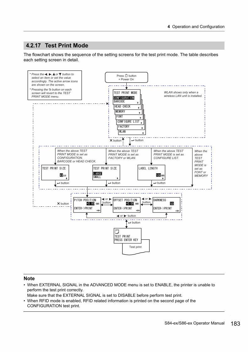
4 Operation and Configuration
4.2.17 Test Print Mode
The flowchart shows the sequence of the setting screens for the test print mode. The table describes each setting screen in detail.
Note• When EXTERNAL SIGNAL in the ADVANCED MODE menu is set to ENABLE, the printer is unable to
perform the test print correctly.Make sure that the EXTERNAL SIGNAL is set to DISABLE before perform test print.
• When RFID mode is enabled, RFID related information is printed on the second page of the CONFIGURATION test print.
Test print
When the above TEST PRINT MODE is set as FONT or MEMORY
Press button+ Power On
When the above TEST PRINT MODE is set as FACTORY or WLAN.
When the above TEST PRINT MODE is set as CONFIGURATION, BARCODE or HEAD CHECK.
or button
or button
or button
* Press the , , or button to select an item or set the value accordingly. The active arrow icons are shown on the screen.
* Pressing the button on each screen will revert to the TEST PRINT MODE menu.
buttonbutton
WLAN shows only when a wireless LAN unit is installed.
button button
button
button
When the above TEST PRINT MODE is set as CONFIGURE LIST.
button
183S84-ex/S86-ex Operator Manual
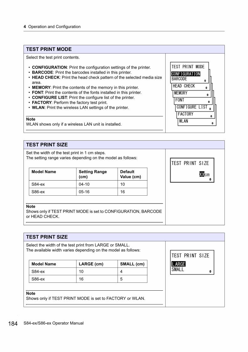
4 Operation and Configuration
184
TEST PRINT MODE
Select the test print contents.
• CONFIGURATION: Print the configuration settings of the printer.• BARCODE: Print the barcodes installed in this printer.• HEAD CHECK: Print the head check pattern of the selected media size
area.• MEMORY: Print the contents of the memory in this printer.• FONT: Print the contents of the fonts installed in this printer.• CONFIGURE LIST: Print the configure list of the printer.• FACTORY: Perform the factory test print.• WLAN: Print the wireless LAN settings of the printer.
NoteWLAN shows only if a wireless LAN unit is installed.
TEST PRINT SIZE
Set the width of the test print in 1 cm steps.The setting range varies depending on the model as follows:
NoteShows only if TEST PRINT MODE is set to CONFIGURATION, BARCODE or HEAD CHECK.
TEST PRINT SIZE
Select the width of the test print from LARGE or SMALL.The available width varies depending on the model as follows:
NoteShows only if TEST PRINT MODE is set to FACTORY or WLAN.
Model Name Setting Range (cm)
Default Value (cm)
S84-ex 04-10 10
S86-ex 05-16 16
Model Name LARGE (cm) SMALL (cm)
S84-ex 10 4
S86-ex 16 5
S84-ex/S86-ex Operator Manual
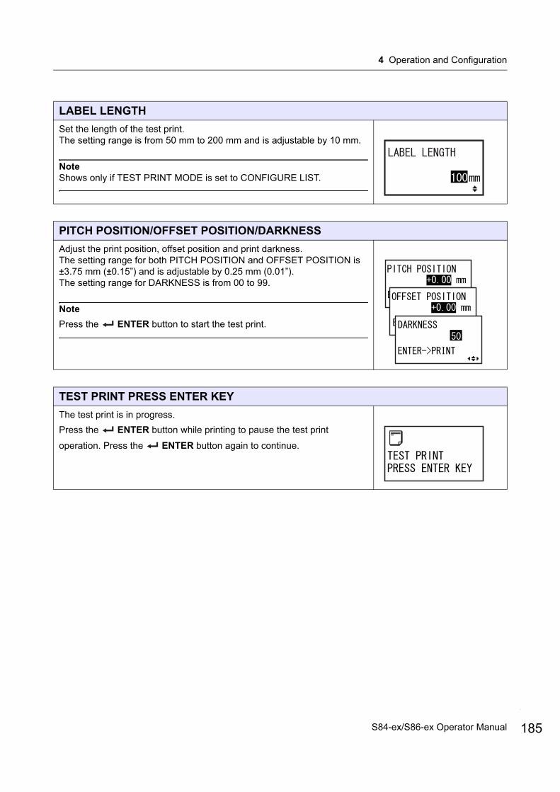
4 Operation and Configuration
LABEL LENGTH
Set the length of the test print.The setting range is from 50 mm to 200 mm and is adjustable by 10 mm.
NoteShows only if TEST PRINT MODE is set to CONFIGURE LIST.
PITCH POSITION/OFFSET POSITION/DARKNESS
Adjust the print position, offset position and print darkness.The setting range for both PITCH POSITION and OFFSET POSITION is ±3.75 mm (±0.15”) and is adjustable by 0.25 mm (0.01”). The setting range for DARKNESS is from 00 to 99.
Note
Press the ENTER button to start the test print.
TEST PRINT PRESS ENTER KEY
The test print is in progress.
Press the ENTER button while printing to pause the test print
operation. Press the ENTER button again to continue.
185S84-ex/S86-ex Operator Manual
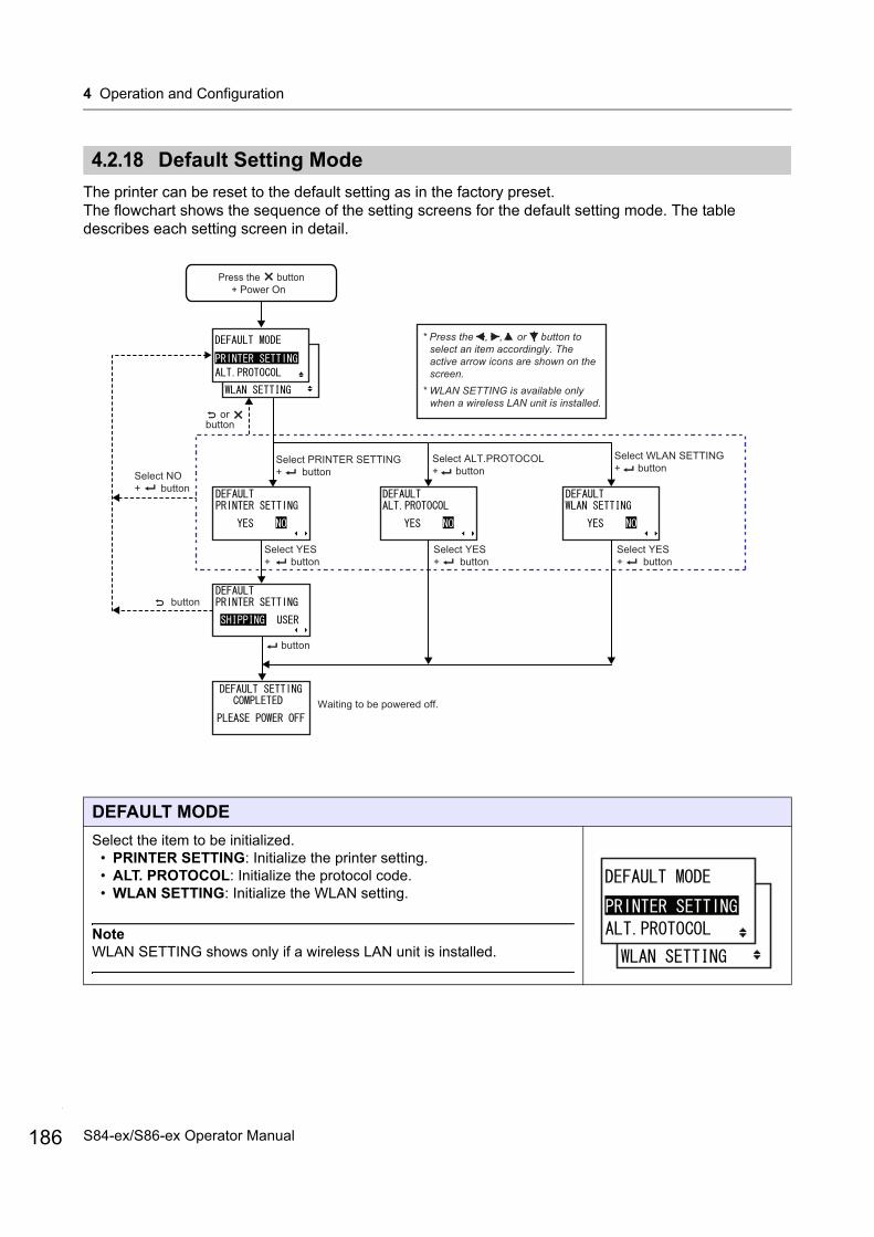
4 Operation and Configuration
186
4.2.18 Default Setting Mode
The printer can be reset to the default setting as in the factory preset.The flowchart shows the sequence of the setting screens for the default setting mode. The table describes each setting screen in detail.
DEFAULT MODE
Select the item to be initialized.• PRINTER SETTING: Initialize the printer setting.• ALT. PROTOCOL: Initialize the protocol code.• WLAN SETTING: Initialize the WLAN setting.
NoteWLAN SETTING shows only if a wireless LAN unit is installed.
Select ALT.PROTOCOL + button
Press the button+ Power On
Select PRINTER SETTING + button
Select YES + button
* Press the , , or button to select an item accordingly. The active arrow icons are shown on the screen.
* WLAN SETTING is available only when a wireless LAN unit is installed.
Waiting to be powered off.
or button
Select WLAN SETTING + button
Select NO + button
button
button
Select YES + button
Select YES + button
S84-ex/S86-ex Operator Manual
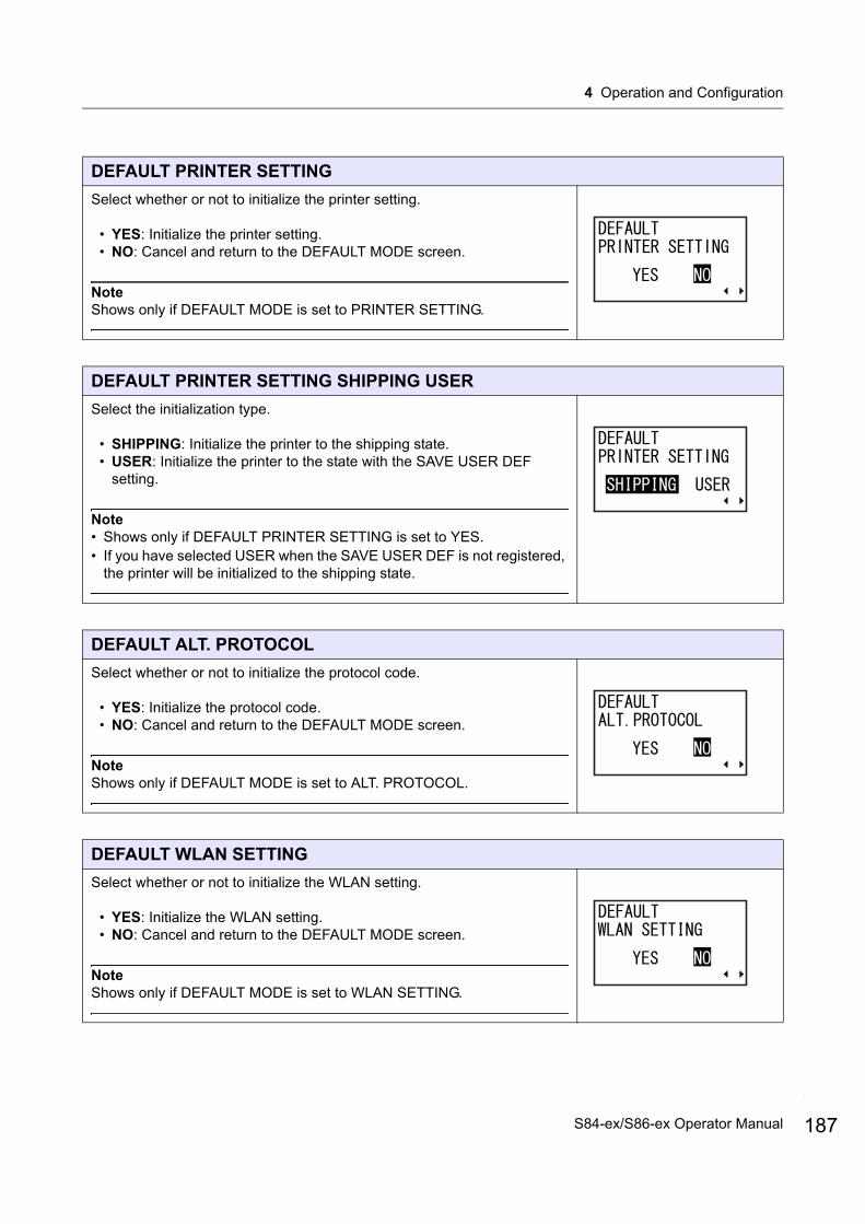
4 Operation and Configuration
DEFAULT PRINTER SETTING
Select whether or not to initialize the printer setting.
• YES: Initialize the printer setting.• NO: Cancel and return to the DEFAULT MODE screen.
NoteShows only if DEFAULT MODE is set to PRINTER SETTING.
DEFAULT PRINTER SETTING SHIPPING USER
Select the initialization type.
• SHIPPING: Initialize the printer to the shipping state.• USER: Initialize the printer to the state with the SAVE USER DEF
setting.
Note• Shows only if DEFAULT PRINTER SETTING is set to YES.• If you have selected USER when the SAVE USER DEF is not registered,
the printer will be initialized to the shipping state.
DEFAULT ALT. PROTOCOL
Select whether or not to initialize the protocol code.
• YES: Initialize the protocol code.• NO: Cancel and return to the DEFAULT MODE screen.
NoteShows only if DEFAULT MODE is set to ALT. PROTOCOL.
DEFAULT WLAN SETTING
Select whether or not to initialize the WLAN setting.
• YES: Initialize the WLAN setting.• NO: Cancel and return to the DEFAULT MODE screen.
NoteShows only if DEFAULT MODE is set to WLAN SETTING.
187S84-ex/S86-ex Operator Manual
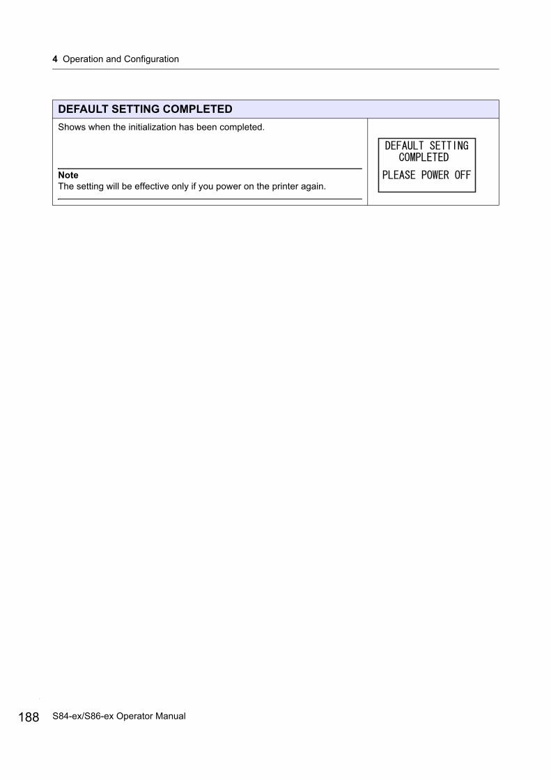
4 Operation and Configuration
188
DEFAULT SETTING COMPLETED
Shows when the initialization has been completed.
NoteThe setting will be effective only if you power on the printer again.
S84-ex/S86-ex Operator Manual
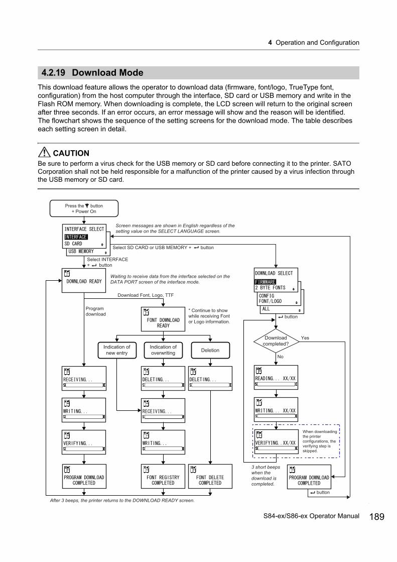
4 Operation and Configuration
4.2.19 Download Mode
This download feature allows the operator to download data (firmware, font/logo, TrueType font, configuration) from the host computer through the interface, SD card or USB memory and write in the Flash ROM memory. When downloading is complete, the LCD screen will return to the original screen after three seconds. If an error occurs, an error message will show and the reason will be identified.The flowchart shows the sequence of the setting screens for the download mode. The table describes each setting screen in detail.
CAUTIONBe sure to perform a virus check for the USB memory or SD card before connecting it to the printer. SATO Corporation shall not be held responsible for a malfunction of the printer caused by a virus infection through the USB memory or SD card.
Download Font, Logo, TTF
Press the button+ Power On
Program download
Indication of new entry
Indication of overwriting Deletion
Screen messages are shown in English regardless of the setting value on the SELECT LANGUAGE screen.
Select INTERFACE + button
After 3 beeps, the printer returns to the DOWNLOAD READY screen.
Downloadcompleted?
Yes
No
When downloading the printer configurations, the verifying step is skipped.
Select SD CARD or USB MEMORY + button
Waiting to receive data from the interface selected on the DATA PORT screen of the interface mode.
* Continue to show while receiving Font or Logo information.
3 short beeps when the download is completed.
button
button
189S84-ex/S86-ex Operator Manual
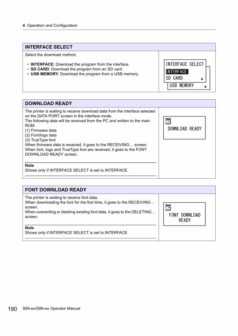
4 Operation and Configuration
190
INTERFACE SELECT
Select the download method.
• INTERFACE: Download the program from the interface.• SD CARD: Download the program from an SD card.• USB MEMORY: Download the program from a USB memory.
DOWNLOAD READY
The printer is waiting to receive download data from the interface selected on the DATA PORT screen in the interface mode.The following data will be received from the PC and written to the main ROM.(1) Firmware data(2) Font/logo data(3) TrueType fontWhen firmware data is received, it goes to the RECEIVING… screen.When font, logo and TrueType font are received, it goes to the FONT DOWNLOAD READY screen.
NoteShows only if INTERFACE SELECT is set to INTERFACE.
FONT DOWNLOAD READY
The printer is waiting to receive font data.When downloading the font for the first time, it goes to the RECEIVING… screen.When overwriting or deleting existing font data, it goes to the DELETING… screen.
NoteShows only if INTERFACE SELECT is set to INTERFACE.
S84-ex/S86-ex Operator Manual
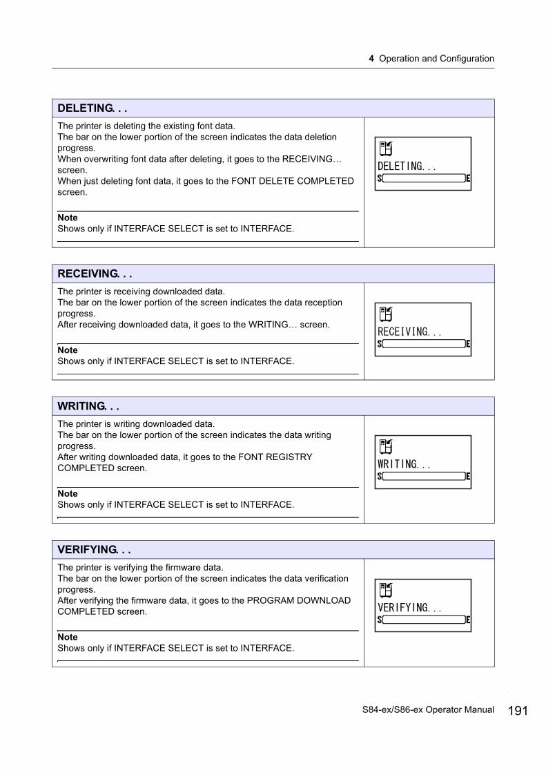
4 Operation and Configuration
DELETING. . .
The printer is deleting the existing font data.The bar on the lower portion of the screen indicates the data deletion progress.When overwriting font data after deleting, it goes to the RECEIVING… screen.When just deleting font data, it goes to the FONT DELETE COMPLETED screen.
NoteShows only if INTERFACE SELECT is set to INTERFACE.
RECEIVING. . .
The printer is receiving downloaded data.The bar on the lower portion of the screen indicates the data reception progress.After receiving downloaded data, it goes to the WRITING… screen.
NoteShows only if INTERFACE SELECT is set to INTERFACE.
WRITING. . .
The printer is writing downloaded data.The bar on the lower portion of the screen indicates the data writing progress.After writing downloaded data, it goes to the FONT REGISTRY COMPLETED screen.
NoteShows only if INTERFACE SELECT is set to INTERFACE.
VERIFYING. . .
The printer is verifying the firmware data.The bar on the lower portion of the screen indicates the data verification progress.After verifying the firmware data, it goes to the PROGRAM DOWNLOAD COMPLETED screen.
NoteShows only if INTERFACE SELECT is set to INTERFACE.
191S84-ex/S86-ex Operator Manual

4 Operation and Configuration
192
PROGRAM DOWNLOAD COMPLETED
This screen shows the completion of the download.Three beeps will sound when the program download is completed.If downloading through INTERFACE, it will return to the DOWNLOAD READY screen.
If downloading through SD CARD or USB MEMORY, press the ENTER button to return to the INTERFACE SELECT screen.
FONT REGISTRY COMPLETED
This screen shows the completion of the font registry.Three beeps will sound when the font registry is completed.The printer returns to the DOWNLOAD READY screen.
NoteShows only if INTERFACE SELECT is set to INTERFACE.
FONT DELETE COMPLETED
This screen shows the completion of the font deletion.Three beeps will sound when the font deletion is completed.The printer returns to the DOWNLOAD READY screen.
NoteShows only if INTERFACE SELECT is set to INTERFACE.
DOWNLOAD SELECT
Select the item to be downloaded.
• FIRMWARE: Download “Firmware”, “2 byte fonts” and “Outline font”.• 2 BYTE FONTS: Download “2 byte fonts” and “Outline font”.• CONFIG: Download printer configurations.• FONT/LOGO: Download font/logo data.• ALL: Download all data.
NoteShows only if INTERFACE SELECT is set to SD CARD or USB MEMORY.
S84-ex/S86-ex Operator Manual

4 Operation and Configuration
READING. . . XX/XX (DOWNLOAD)
The printer is reading the downloaded data.The bar on the lower portion of the screen indicates the data reading progress.XX/XX shows the file number being read and total number of files.After reading the data, it goes to the WRITING… screen.
NoteShows only if INTERFACE SELECT is set to SD CARD or USB MEMORY.
WRITING. . . XX/XX (DOWNLOAD)
The printer is writing the downloaded data.The bar on the lower portion of the screen indicates the data writing progress.XX/XX shows the file number being written and total number of files.After writing the data, it goes to the VERIFYING... screen.
NoteShows only if INTERFACE SELECT is set to SD CARD or USB MEMORY.
VERIFYING. . . XX/XX (DOWNLOAD)
The printer is verifying the downloaded data.The bar on the lower portion of the screen indicates the data verification progress.XX/XX shows the file number being verified and total number of files.After verifying the data, it goes to the PROGRAM DOWNLOAD COMPLETED screen.
NoteShows only if INTERFACE SELECT is set to SD CARD or USB MEMORY.
193S84-ex/S86-ex Operator Manual

4 Operation and Configuration
194
4.2.20 Upload Mode
The upload feature allows the operator to upload data (firmware, font/logo, TrueType font, configuration, status5 log) from the printer and write it to an SD card or USB memory. When uploading is complete, the LCD screen will return to the original screen after three seconds. If an error occurs, an error message will show and the reason will be identified.
CAUTIONBe sure to perform a virus check for the USB memory or SD card before connecting it to the printer. SATO Corporation shall not be held responsible for a malfunction of the printer caused by a virus infection through the USB memory or SD card.
Press button+ Power On
・ If the item selected on the UPLOAD SELECT screen does not have data to be uploaded, nothing will be uploaded.
・ Selecting ALL will upload all the items on the UPLOAD SELECT screen.
・ Screen messages are shown in English regardless of the setting value on the SELECT LANGUAGE screen.
Uploadcompleted?
Yes
No
Reading the data
Writing the data
Finished receiving the uploaded data
Finished writing the uploaded data
3 short beeps when the upload is completed
button
button
button
S84-ex/S86-ex Operator Manual
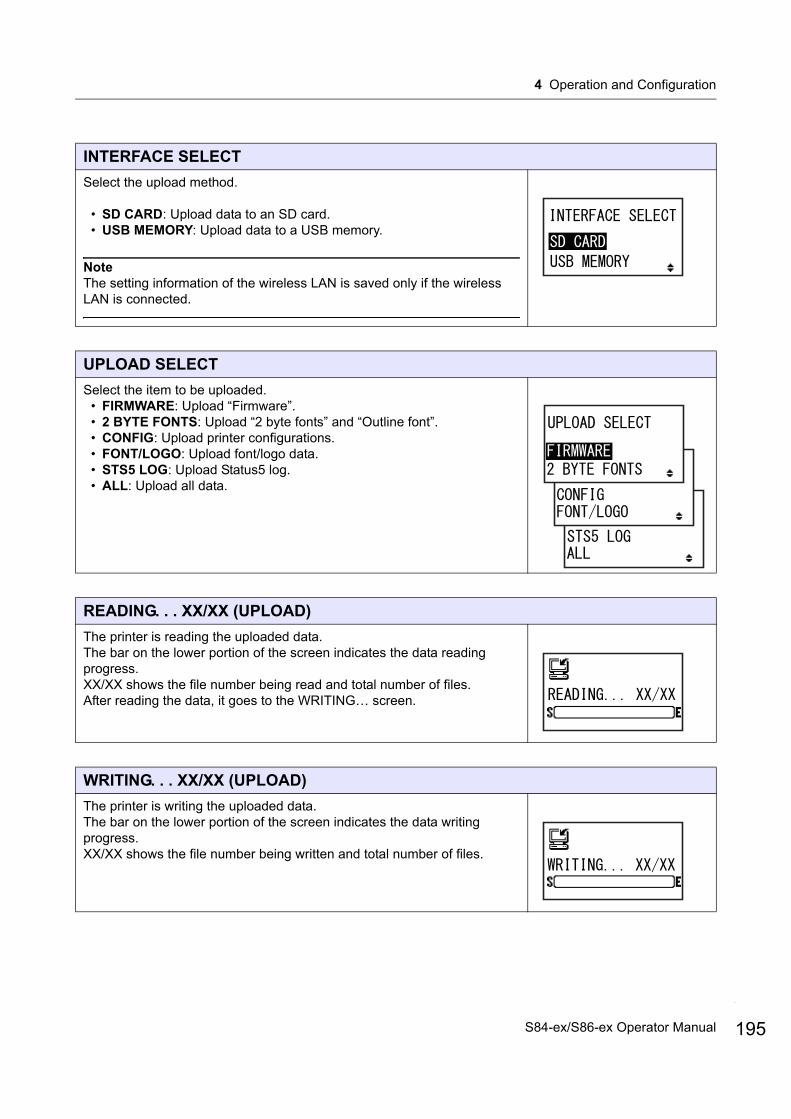
4 Operation and Configuration
INTERFACE SELECT
Select the upload method.
• SD CARD: Upload data to an SD card.• USB MEMORY: Upload data to a USB memory.
NoteThe setting information of the wireless LAN is saved only if the wireless LAN is connected.
UPLOAD SELECT
Select the item to be uploaded.• FIRMWARE: Upload “Firmware”.• 2 BYTE FONTS: Upload “2 byte fonts” and “Outline font”.• CONFIG: Upload printer configurations.• FONT/LOGO: Upload font/logo data.• STS5 LOG: Upload Status5 log.• ALL: Upload all data.
READING. . . XX/XX (UPLOAD)
The printer is reading the uploaded data.The bar on the lower portion of the screen indicates the data reading progress.XX/XX shows the file number being read and total number of files.After reading the data, it goes to the WRITING… screen.
WRITING. . . XX/XX (UPLOAD)
The printer is writing the uploaded data.The bar on the lower portion of the screen indicates the data writing progress.XX/XX shows the file number being written and total number of files.
195S84-ex/S86-ex Operator Manual

4 Operation and Configuration
196
4.2.21 Hidden Setting Mode
This mode allows the operator access to set the label out sensor status and work shift mode status.The flowchart shows the sequence of the setting screens for the hidden setting mode. The table describes each setting screen in detail.
PROGRAM UPLOAD COMPLETED
This screen shows the completion of the upload.Three beeps will sound when the program upload is completed.
Press the ENTER button to return to the INTERFACE SELECT screen.
LABEL OUT SENSOR
Enable or disable the paper end detection.
• YES: Enable the paper end detection.• NO: Disable the paper end detection.
SHIFT CODE
Enable or disable the work shift setting mode.
• YES: Enable the work shift setting mode.• NO: Disable the work shift setting mode.
NoteFor details on the work shift setting mode, refer to Section 4.2.6 Work Shift Setting Mode.
+ + +Power on
or button
or button
S84-ex/S86-ex Operator Manual

4 Operation and Configuration
4.2.22 Wireless LAN Certificate Download Mode
This mode allows the user to download the wireless LAN certification data.The flowchart shows the sequence of the setting screens for the wireless LAN certificate download mode. The table describes each setting screen in detail.
CAUTIONBe sure to perform a virus check for the USB memory or SD card before connecting it to the printer. SATO Corporation shall not be held responsible for a malfunction of the printer caused by a virus infection through the USB memory or SD card.
File?No
Yes
Waiting to be powered off.
+ +Power on
button
Waiting to be powered off.
197S84-ex/S86-ex Operator Manual
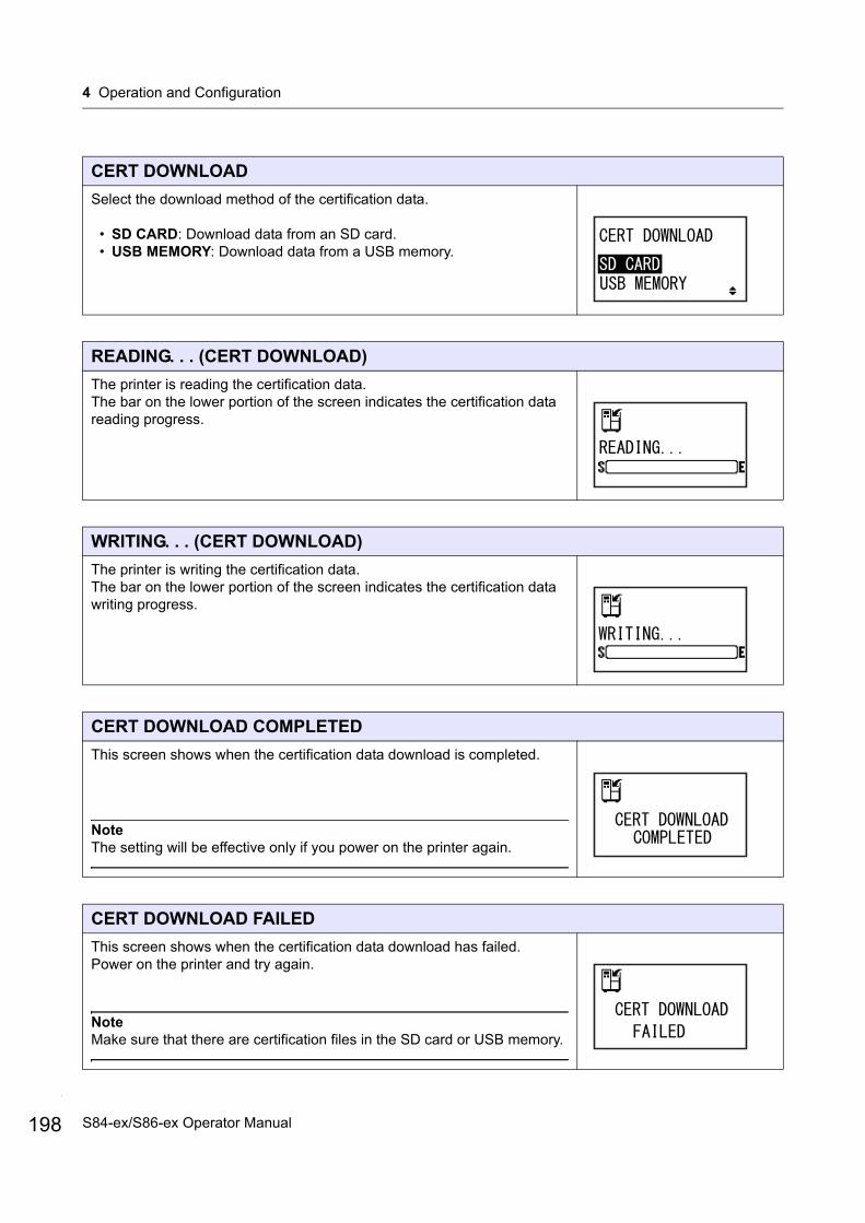
4 Operation and Configuration
198
CERT DOWNLOAD
Select the download method of the certification data.
• SD CARD: Download data from an SD card.• USB MEMORY: Download data from a USB memory.
READING. . . (CERT DOWNLOAD)
The printer is reading the certification data.The bar on the lower portion of the screen indicates the certification data reading progress.
WRITING. . . (CERT DOWNLOAD)
The printer is writing the certification data.The bar on the lower portion of the screen indicates the certification data writing progress.
CERT DOWNLOAD COMPLETED
This screen shows when the certification data download is completed.
NoteThe setting will be effective only if you power on the printer again.
CERT DOWNLOAD FAILED
This screen shows when the certification data download has failed.Power on the printer and try again.
NoteMake sure that there are certification files in the SD card or USB memory.
S84-ex/S86-ex Operator Manual

4 Operation and Configuration
4.2.23 Site Survey Mode
This mode allows you to acquire the information of access points.The flowchart shows the sequence of the setting screens for the site survey mode. The table describes each setting screen in detail.
Site survey mode stops when powered off.
+ +Power on
Infrastructure is selectedin the WIRELESS MODEof the WLAN interface setting.
Site survey mode stops when powered off.
button
Ad Hoc is selected in the WIRELESS MODE of the WLAN interface setting.
buttonbutton
button
buttonbutton
(1) The order of field intensity (1 is stronger)(2) MAC address(3) MAC address (lower 6 digits)(4) Used channel(5) RSSI value [dBm] (absolute value)
button
button
button
button
When AP is not found
button button button button
Print completion
(1) (1)(3) (2)(4) (5)
* In Site survey mode, the printer prints only one label. After the print completion or error release, the printer returns to the list screen.
button
button
199S84-ex/S86-ex Operator Manual
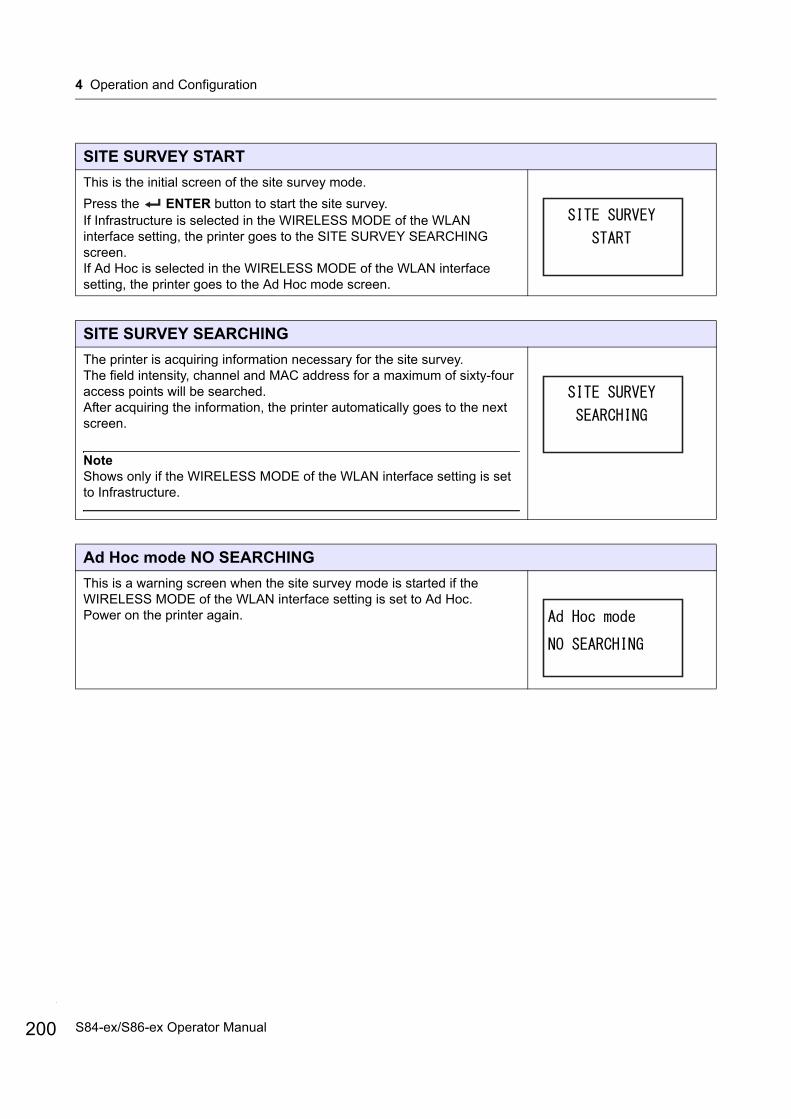
4 Operation and Configuration
200
SITE SURVEY START
This is the initial screen of the site survey mode.
Press the ENTER button to start the site survey.If Infrastructure is selected in the WIRELESS MODE of the WLAN interface setting, the printer goes to the SITE SURVEY SEARCHING screen.If Ad Hoc is selected in the WIRELESS MODE of the WLAN interface setting, the printer goes to the Ad Hoc mode screen.
SITE SURVEY SEARCHING
The printer is acquiring information necessary for the site survey.The field intensity, channel and MAC address for a maximum of sixty-four access points will be searched.After acquiring the information, the printer automatically goes to the next screen.
NoteShows only if the WIRELESS MODE of the WLAN interface setting is set to Infrastructure.
Ad Hoc mode NO SEARCHING
This is a warning screen when the site survey mode is started if the WIRELESS MODE of the WLAN interface setting is set to Ad Hoc.Power on the printer again.
S84-ex/S86-ex Operator Manual
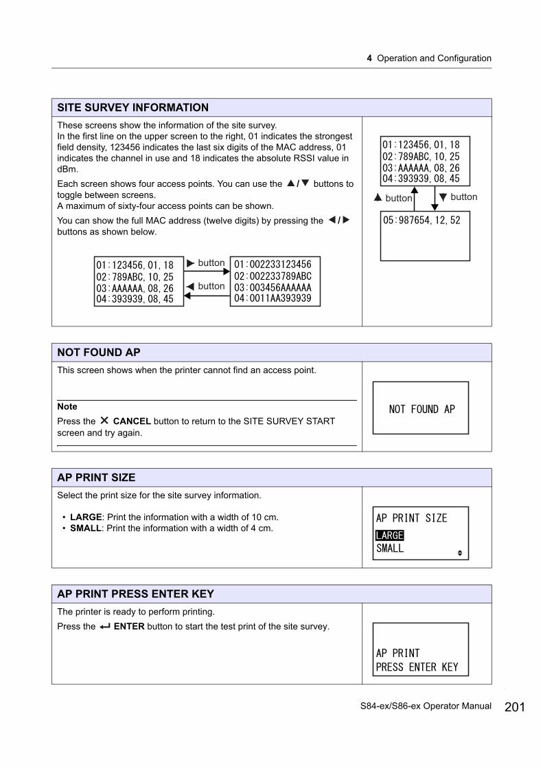
4 Operation and Configuration
SITE SURVEY INFORMATION
These screens show the information of the site survey.In the first line on the upper screen to the right, 01 indicates the strongest field density, 123456 indicates the last six digits of the MAC address, 01 indicates the channel in use and 18 indicates the absolute RSSI value in dBm.
Each screen shows four access points. You can use the / buttons to toggle between screens.A maximum of sixty-four access points can be shown.
You can show the full MAC address (twelve digits) by pressing the / buttons as shown below.
NOT FOUND AP
This screen shows when the printer cannot find an access point.
Note
Press the CANCEL button to return to the SITE SURVEY START screen and try again.
AP PRINT SIZE
Select the print size for the site survey information.
• LARGE: Print the information with a width of 10 cm.• SMALL: Print the information with a width of 4 cm.
AP PRINT PRESS ENTER KEY
The printer is ready to perform printing.
Press the ENTER button to start the test print of the site survey.
button
button
button button
201S84-ex/S86-ex Operator Manual
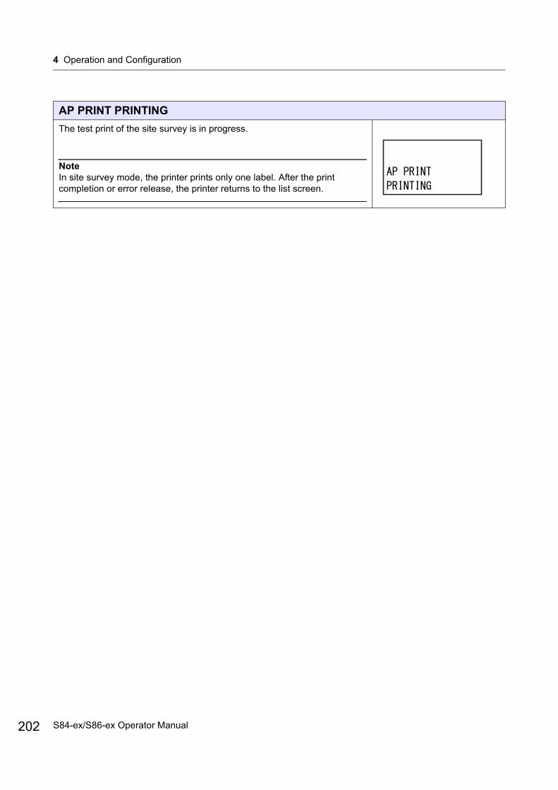
4 Operation and Configuration
202
AP PRINT PRINTING
The test print of the site survey is in progress.
NoteIn site survey mode, the printer prints only one label. After the print completion or error release, the printer returns to the list screen.
S84-ex/S86-ex Operator Manual
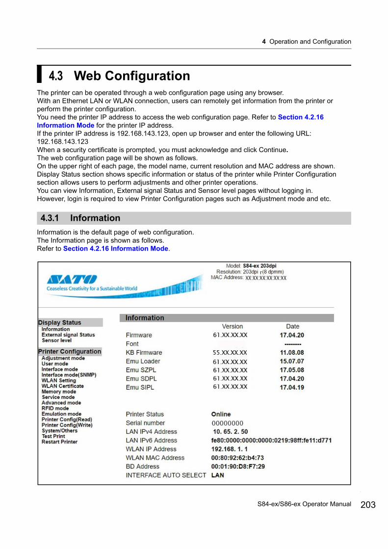
4 Operation and Configuration
4.3 Web ConfigurationThe printer can be operated through a web configuration page using any browser.With an Ethernet LAN or WLAN connection, users can remotely get information from the printer or perform the printer configuration.You need the printer IP address to access the web configuration page. Refer to Section 4.2.16 Information Mode for the printer IP address.If the printer IP address is 192.168.143.123, open up browser and enter the following URL:192.168.143.123When a security certificate is prompted, you must acknowledge and click Continue. The web configuration page will be shown as follows.On the upper right of each page, the model name, current resolution and MAC address are shown.Display Status section shows specific information or status of the printer while Printer Configuration section allows users to perform adjustments and other printer operations.You can view Information, External signal Status and Sensor level pages without logging in.However, login is required to view Printer Configuration pages such as Adjustment mode and etc.
4.3.1 Information
Information is the default page of web configuration. The Information page is shown as follows.Refer to Section 4.2.16 Information Mode.
203S84-ex/S86-ex Operator Manual

4 Operation and Configuration
204
4.3.2 External Signal Status
The External signal Status page is shown as follows.Refer to Section 8.5 Input/Output Signal of the External Signal.
S84-ex/S86-ex Operator Manual
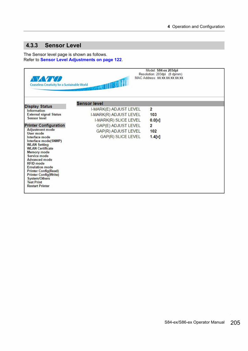
4 Operation and Configuration
4.3.3 Sensor Level
The Sensor level page is shown as follows.Refer to Sensor Level Adjustments on page 122.
205S84-ex/S86-ex Operator Manual
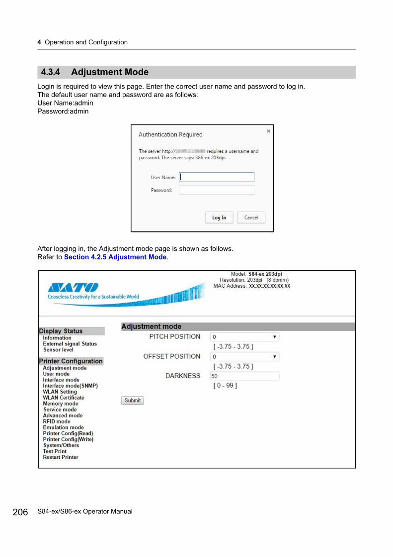
4 Operation and Configuration
206
4.3.4 Adjustment Mode
Login is required to view this page. Enter the correct user name and password to log in.The default user name and password are as follows:User Name:adminPassword:admin
After logging in, the Adjustment mode page is shown as follows.Refer to Section 4.2.5 Adjustment Mode.
S84-ex/S86-ex Operator Manual
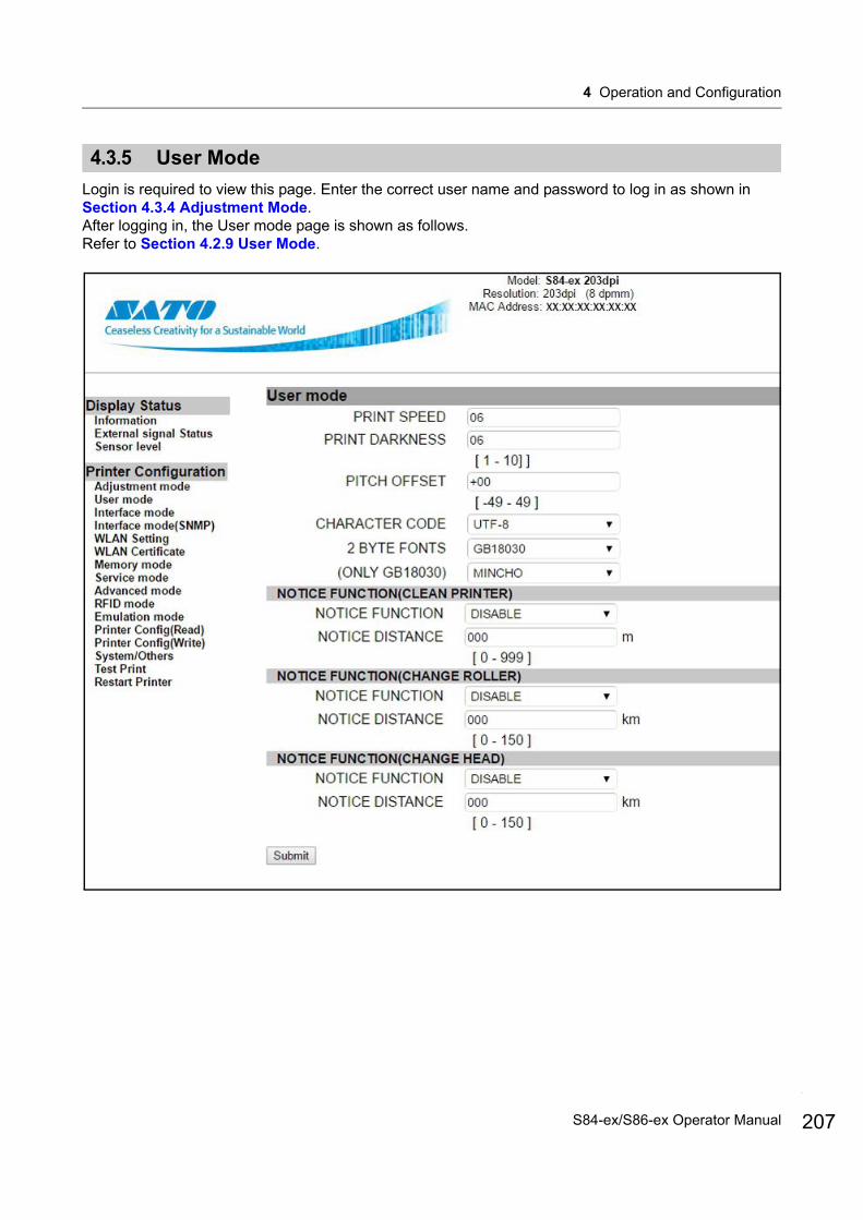
4 Operation and Configuration
4.3.5 User Mode
Login is required to view this page. Enter the correct user name and password to log in as shown in Section 4.3.4 Adjustment Mode.After logging in, the User mode page is shown as follows.Refer to Section 4.2.9 User Mode.
207S84-ex/S86-ex Operator Manual
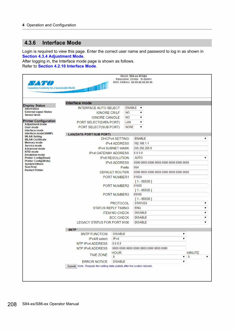
4 Operation and Configuration
208
4.3.6 Interface Mode
Login is required to view this page. Enter the correct user name and password to log in as shown in Section 4.3.4 Adjustment Mode.After logging in, the Interface mode page is shown as follows.Refer to Section 4.2.10 Interface Mode.
S84-ex/S86-ex Operator Manual

4 Operation and Configuration
4.3.7 Interface Mode (SNMP)
Login is required to view this page. Enter the correct user name and password to log in as shown in Section 4.3.4 Adjustment Mode.After logging in, the Interface mode (SNMP) page is shown as follows (continued to the next page).Refer to SNMP FUNCTION on page 84.
209S84-ex/S86-ex Operator Manual

4 Operation and Configuration
210
S84-ex/S86-ex Operator Manual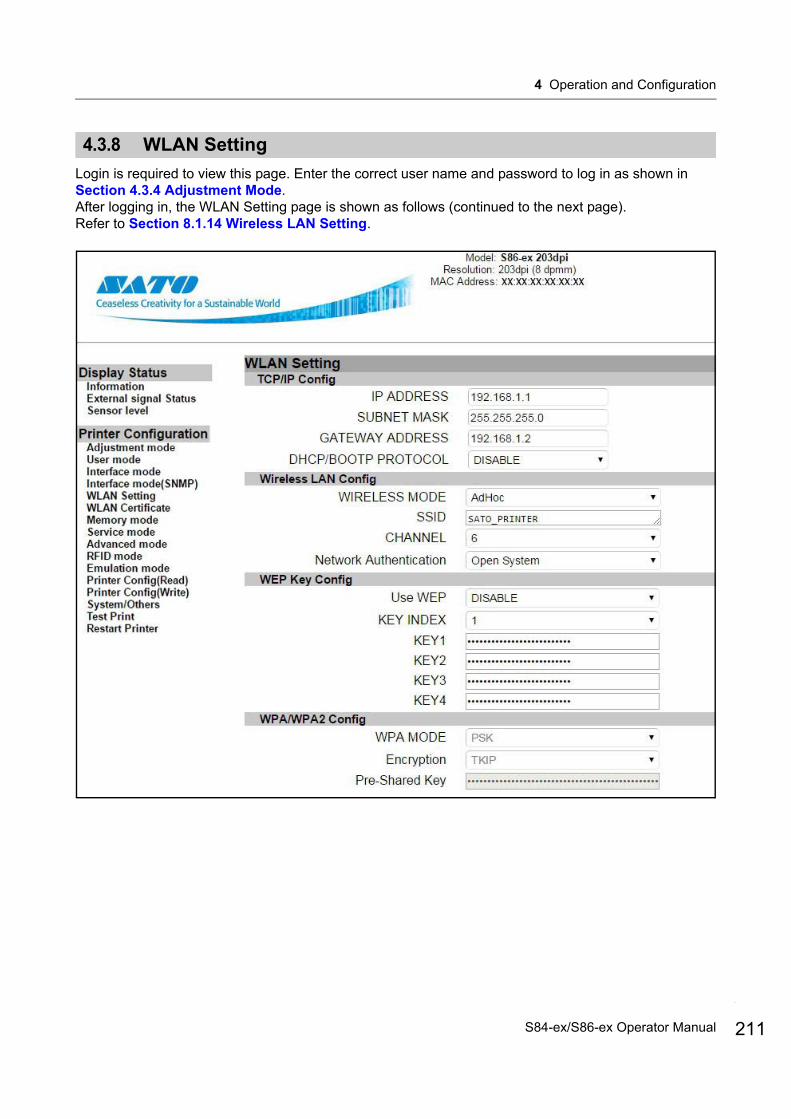
4 Operation and Configuration
4.3.8 WLAN Setting
Login is required to view this page. Enter the correct user name and password to log in as shown in Section 4.3.4 Adjustment Mode.After logging in, the WLAN Setting page is shown as follows (continued to the next page).Refer to Section 8.1.14 Wireless LAN Setting.
211S84-ex/S86-ex Operator Manual
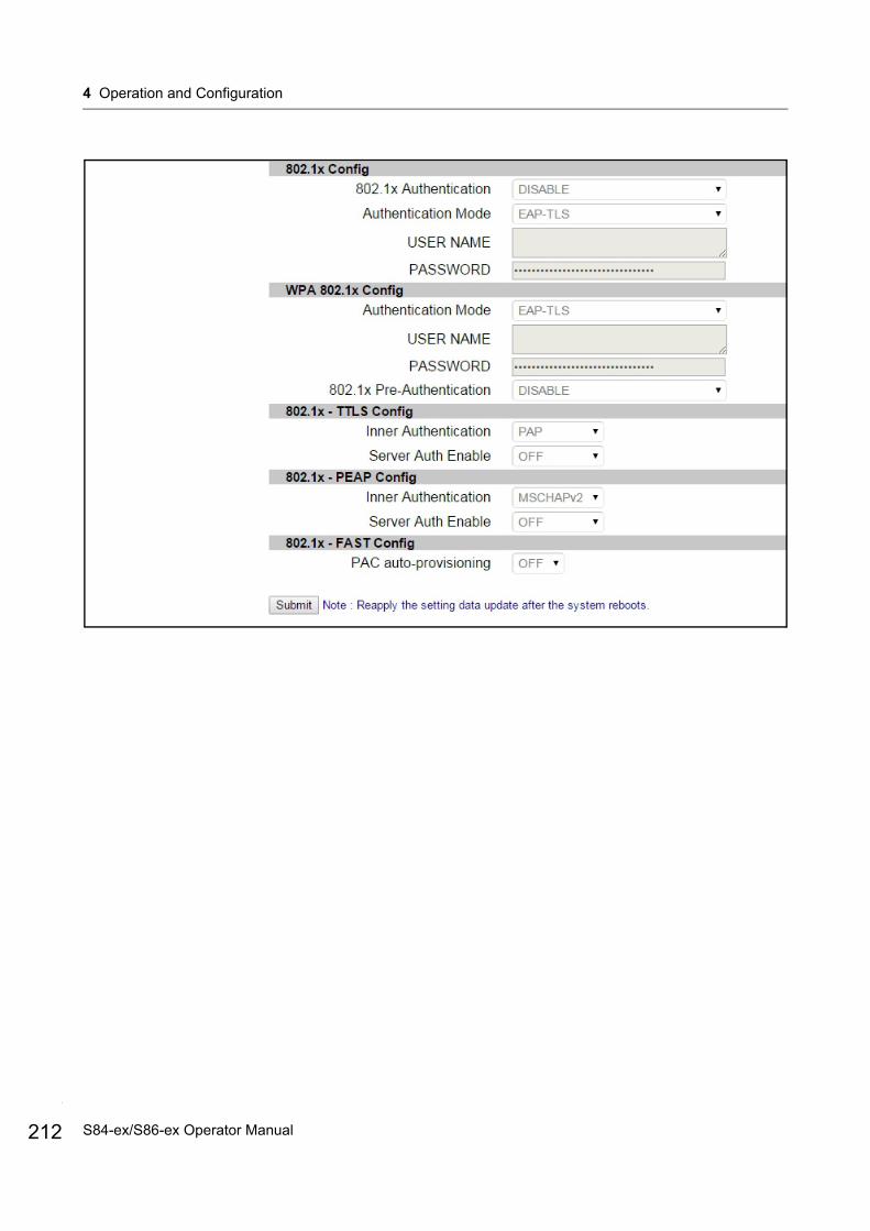
4 Operation and Configuration
212
S84-ex/S86-ex Operator Manual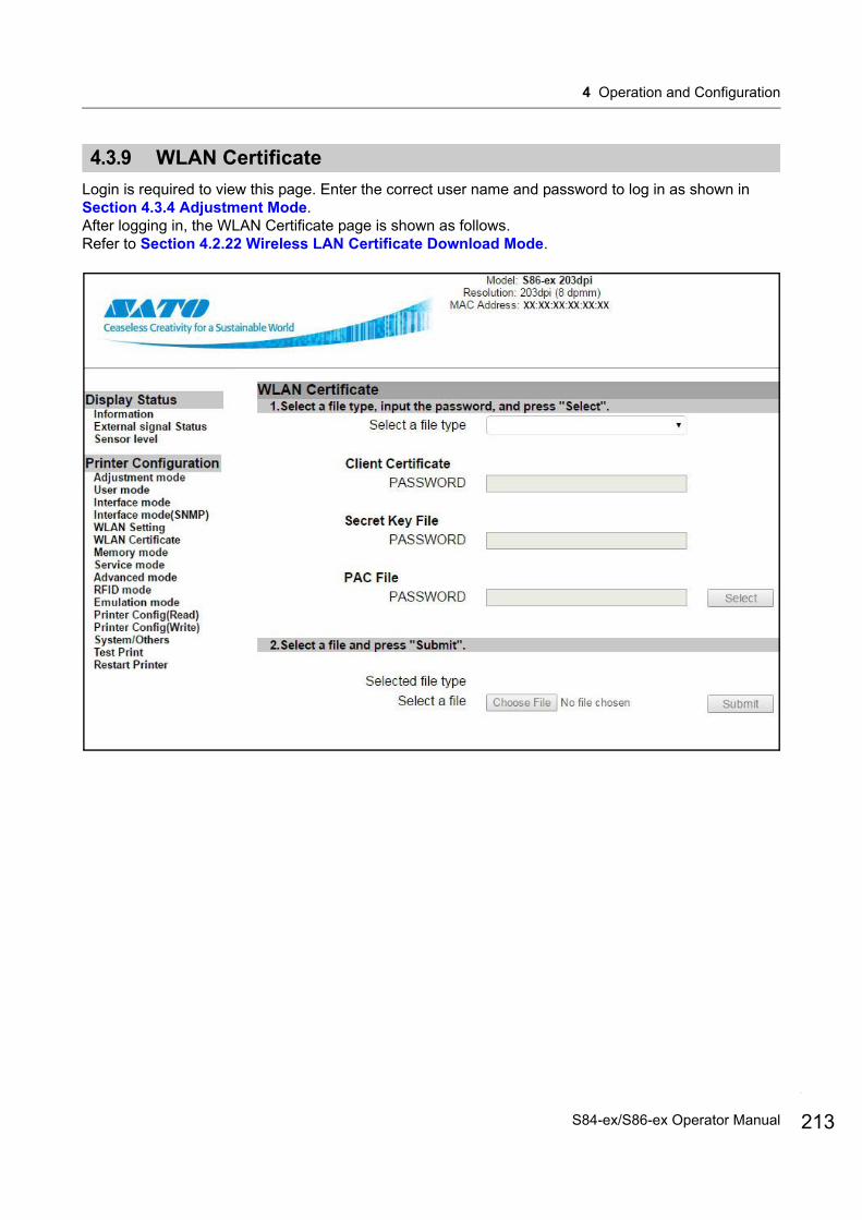
4 Operation and Configuration
4.3.9 WLAN Certificate
Login is required to view this page. Enter the correct user name and password to log in as shown in Section 4.3.4 Adjustment Mode.After logging in, the WLAN Certificate page is shown as follows.Refer to Section 4.2.22 Wireless LAN Certificate Download Mode.
213S84-ex/S86-ex Operator Manual

4 Operation and Configuration
214
4.3.10 Memory Mode
Login is required to view this page. Enter the correct user name and password to log in as shown in Section 4.3.4 Adjustment Mode.After logging in, the Memory mode page is shown as follows.Refer to Section 4.2.11 Memory Mode.
S84-ex/S86-ex Operator Manual
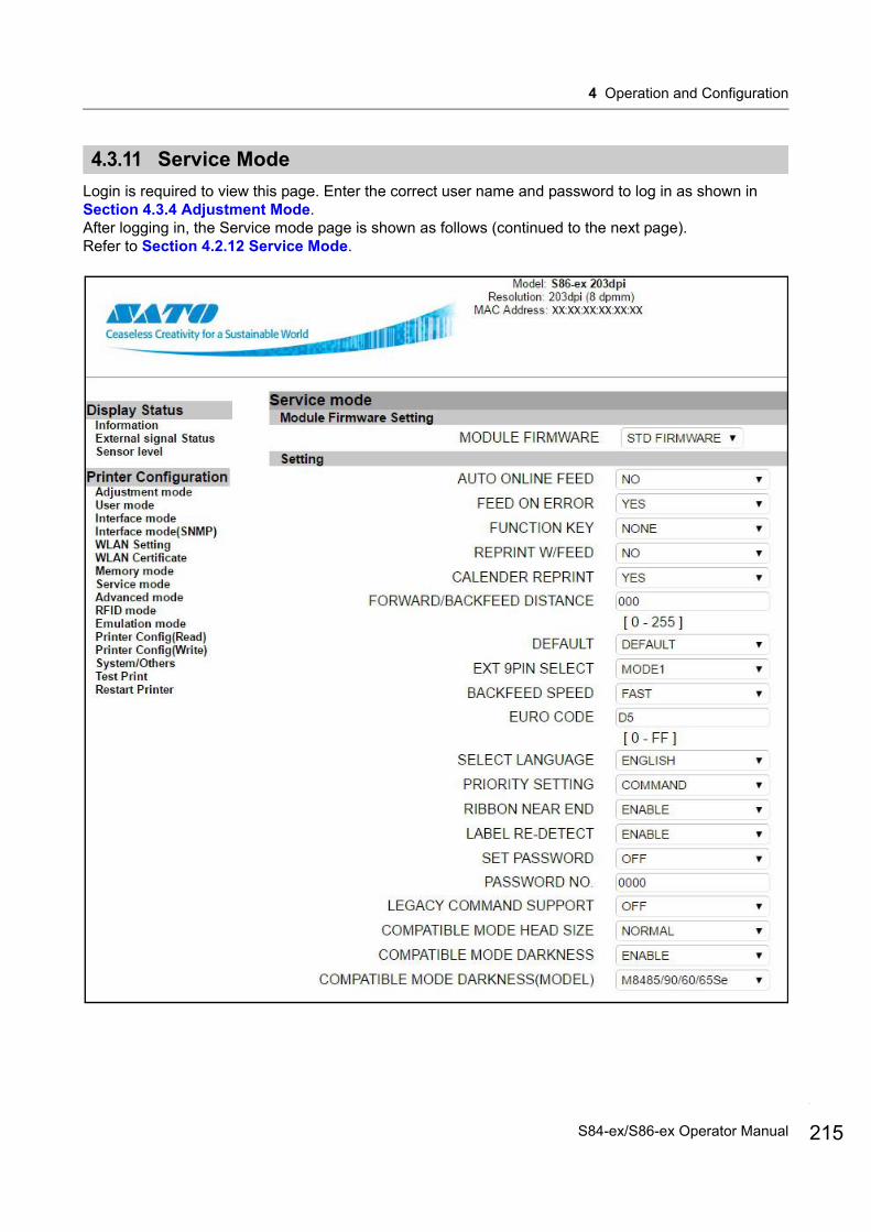
4 Operation and Configuration
4.3.11 Service Mode
Login is required to view this page. Enter the correct user name and password to log in as shown in Section 4.3.4 Adjustment Mode.After logging in, the Service mode page is shown as follows (continued to the next page).Refer to Section 4.2.12 Service Mode.
215S84-ex/S86-ex Operator Manual
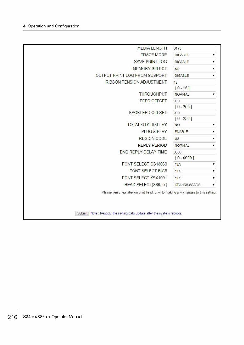
4 Operation and Configuration
216
S84-ex/S86-ex Operator Manual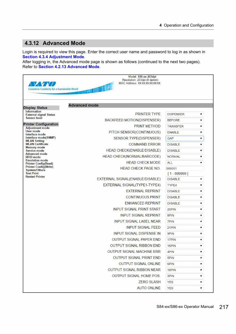
4 Operation and Configuration
4.3.12 Advanced Mode
Login is required to view this page. Enter the correct user name and password to log in as shown in Section 4.3.4 Adjustment Mode.After logging in, the Advanced mode page is shown as follows (continued to the next two pages).Refer to Section 4.2.13 Advanced Mode.
217S84-ex/S86-ex Operator Manual
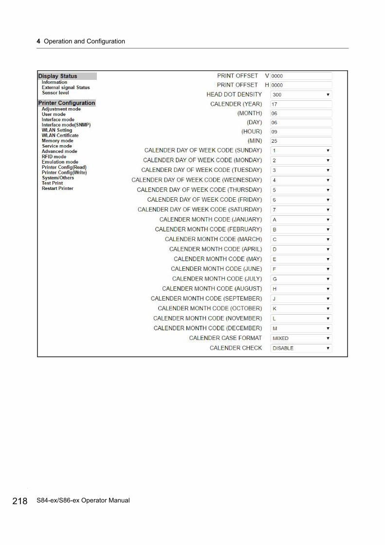
4 Operation and Configuration
218
S84-ex/S86-ex Operator Manual
4 Operation and Configuration
219S84-ex/S86-ex Operator Manual

4 Operation and Configuration
220
4.3.13 RFID Mode
Login is required to view this page. Enter the correct user name and password to log in as shown in Section 4.3.4 Adjustment Mode.After logging in, the RFID mode page is shown as follows.Refer to Section 2.1.4 RFID Mode of the S84-ex/S86-ex service manual.
S84-ex/S86-ex Operator Manual

4 Operation and Configuration
4.3.14 Emulation Mode
Login is required to view this page. Enter the correct user name and password to log in as shown in Section 4.3.4 Adjustment Mode.After logging in, the Emulation mode page is shown as follows (continued to the next page).Refer to Section 5.2 SZPL Emulation Mode, Section 5.3 SDPL Emulation Mode or Section 5.4 SIPL Emulation Mode.
221S84-ex/S86-ex Operator Manual
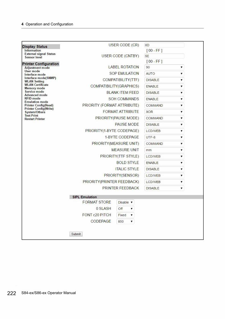
4 Operation and Configuration
222
S84-ex/S86-ex Operator Manual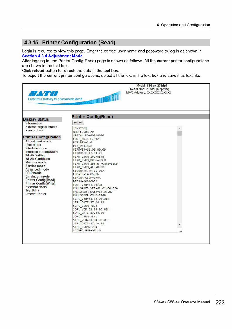
4 Operation and Configuration
4.3.15 Printer Configuration (Read)
Login is required to view this page. Enter the correct user name and password to log in as shown in Section 4.3.4 Adjustment Mode.After logging in, the Printer Config(Read) page is shown as follows. All the current printer configurations are shown in the text box.Click reload button to refresh the data in the text box.To export the current printer configurations, select all the text in the text box and save it as text file.
223S84-ex/S86-ex Operator Manual
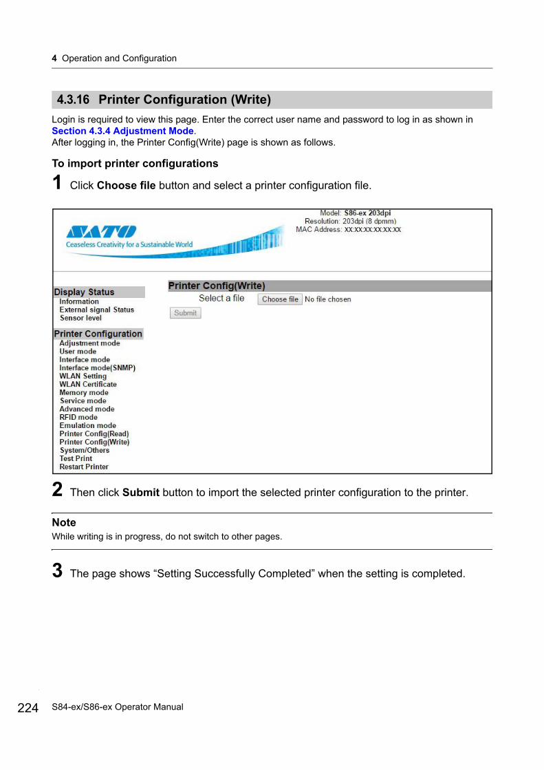
4 Operation and Configuration
224
4.3.16 Printer Configuration (Write)
Login is required to view this page. Enter the correct user name and password to log in as shown in Section 4.3.4 Adjustment Mode.After logging in, the Printer Config(Write) page is shown as follows.
To import printer configurations
1 Click Choose file button and select a printer configuration file.
2 Then click Submit button to import the selected printer configuration to the printer.
NoteWhile writing is in progress, do not switch to other pages.
3 The page shows “Setting Successfully Completed” when the setting is completed.
S84-ex/S86-ex Operator Manual
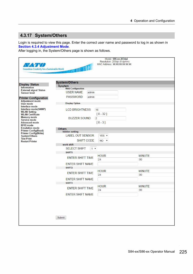
4 Operation and Configuration
4.3.17 System/Others
Login is required to view this page. Enter the correct user name and password to log in as shown in Section 4.3.4 Adjustment Mode.After logging in, the System/Others page is shown as follows.
225S84-ex/S86-ex Operator Manual

4 Operation and Configuration
226
4.3.18 Test Print
Login is required to view this page. Enter the correct user name and password to log in as shown in Section 4.3.4 Adjustment Mode.After logging in, the page is shown as follows.
S84-ex/S86-ex Operator Manual
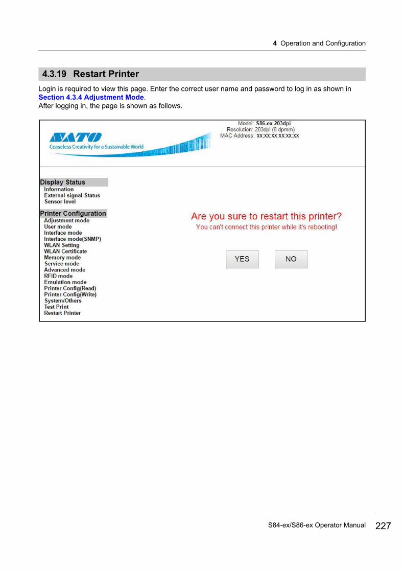
4 Operation and Configuration
4.3.19 Restart Printer
Login is required to view this page. Enter the correct user name and password to log in as shown in Section 4.3.4 Adjustment Mode.After logging in, the page is shown as follows.
227S84-ex/S86-ex Operator Manual
4 Operation and Configuration
228
This page is intentionally left blank.
S84-ex/S86-ex Operator Manual
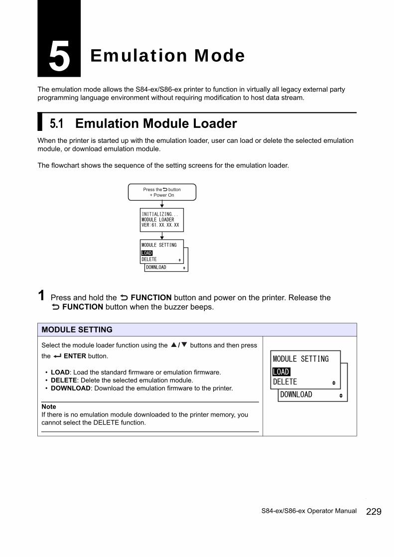
The emulation mode allows the S84-ex/S86-ex printer to function in virtually all legacy external party programming language environment without requiring modification to host data stream.
5.1 Emulation Module LoaderWhen the printer is started up with the emulation loader, user can load or delete the selected emulation module, or download emulation module.
The flowchart shows the sequence of the setting screens for the emulation loader.
1 Press and hold the FUNCTION button and power on the printer. Release the FUNCTION button when the buzzer beeps.
5 Emulation Mode
MODULE SETTING
Select the module loader function using the / buttons and then press
the ENTER button.
• LOAD: Load the standard firmware or emulation firmware.• DELETE: Delete the selected emulation module.• DOWNLOAD: Download the emulation firmware to the printer.
NoteIf there is no emulation module downloaded to the printer memory, you cannot select the DELETE function.
Press the button+ Power On
229S84-ex/S86-ex Operator Manual
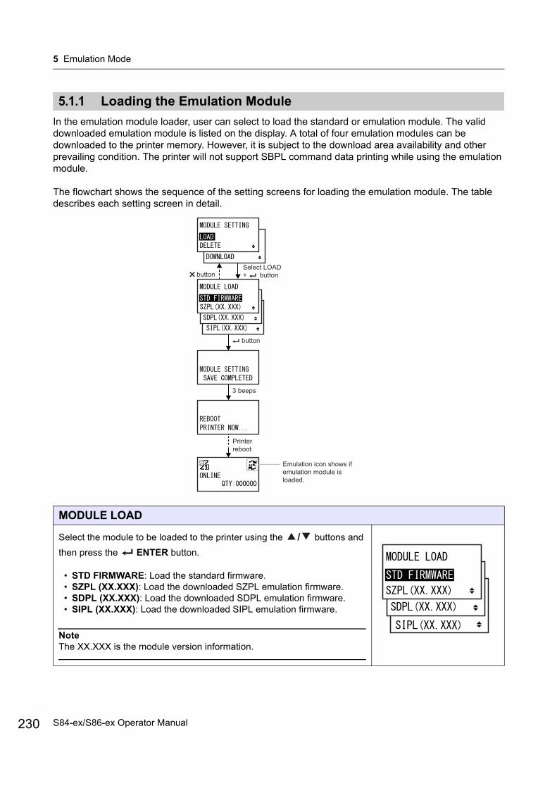
5 Emulation Mode
230
5.1.1 Loading the Emulation Module
In the emulation module loader, user can select to load the standard or emulation module. The valid downloaded emulation module is listed on the display. A total of four emulation modules can be downloaded to the printer memory. However, it is subject to the download area availability and other prevailing condition. The printer will not support SBPL command data printing while using the emulation module.
The flowchart shows the sequence of the setting screens for loading the emulation module. The table describes each setting screen in detail.
MODULE LOAD
Select the module to be loaded to the printer using the / buttons and
then press the ENTER button.
• STD FIRMWARE: Load the standard firmware.• SZPL (XX.XXX): Load the downloaded SZPL emulation firmware.• SDPL (XX.XXX): Load the downloaded SDPL emulation firmware.• SIPL (XX.XXX): Load the downloaded SIPL emulation firmware.
NoteThe XX.XXX is the module version information.
Select LOAD+ button
button
3 beeps
Printer reboot
Emulation icon shows if emulation module is loaded.
button
S84-ex/S86-ex Operator Manual
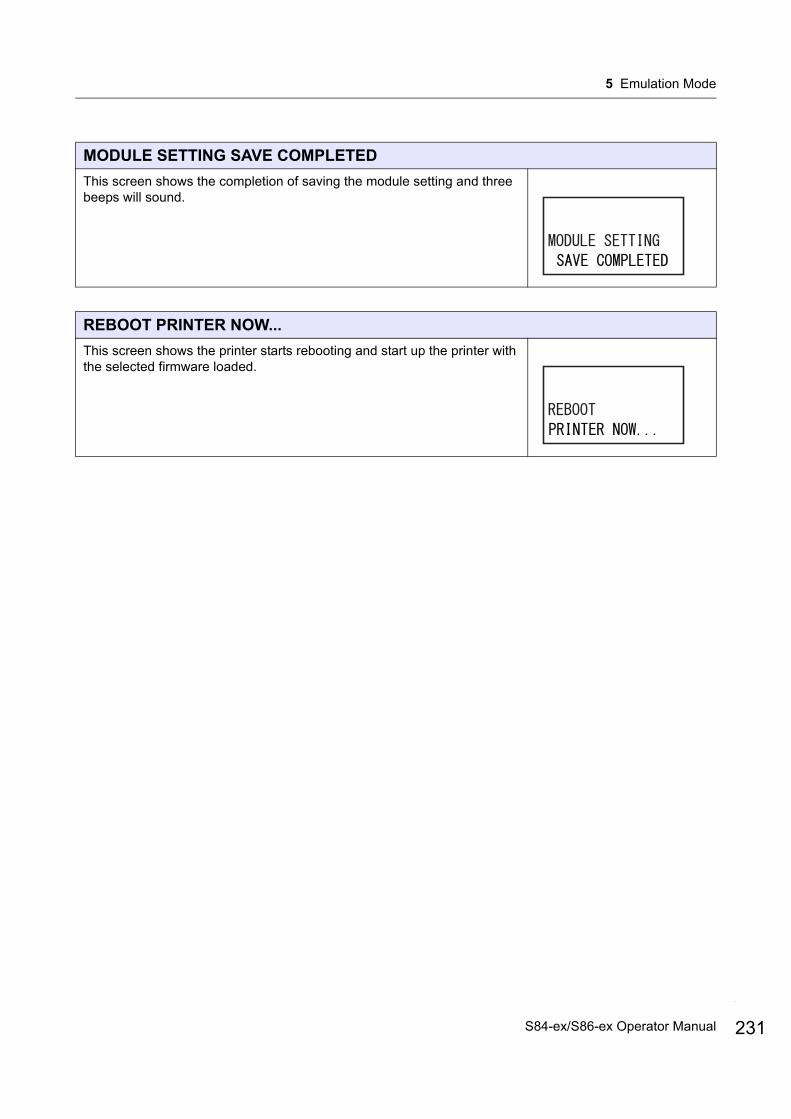
5 Emulation Mode
MODULE SETTING SAVE COMPLETED
This screen shows the completion of saving the module setting and three beeps will sound.
REBOOT PRINTER NOW...
This screen shows the printer starts rebooting and start up the printer with the selected firmware loaded.
231S84-ex/S86-ex Operator Manual
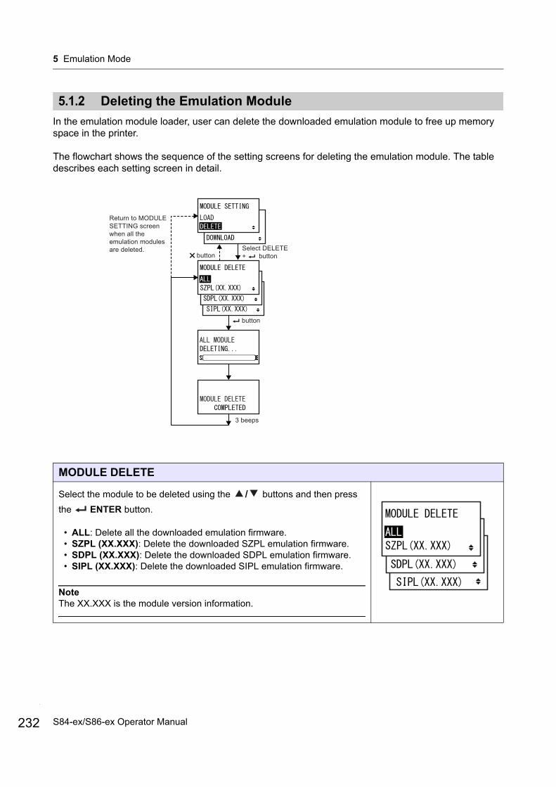
5 Emulation Mode
232
5.1.2 Deleting the Emulation Module
In the emulation module loader, user can delete the downloaded emulation module to free up memory space in the printer.
The flowchart shows the sequence of the setting screens for deleting the emulation module. The table describes each setting screen in detail.
MODULE DELETE
Select the module to be deleted using the / buttons and then press
the ENTER button.
• ALL: Delete all the downloaded emulation firmware.• SZPL (XX.XXX): Delete the downloaded SZPL emulation firmware. • SDPL (XX.XXX): Delete the downloaded SDPL emulation firmware.• SIPL (XX.XXX): Delete the downloaded SIPL emulation firmware.
NoteThe XX.XXX is the module version information.
Select DELETE+ button
button
3 beeps
button
Return to MODULE SETTING screen when all the emulation modules are deleted.
S84-ex/S86-ex Operator Manual
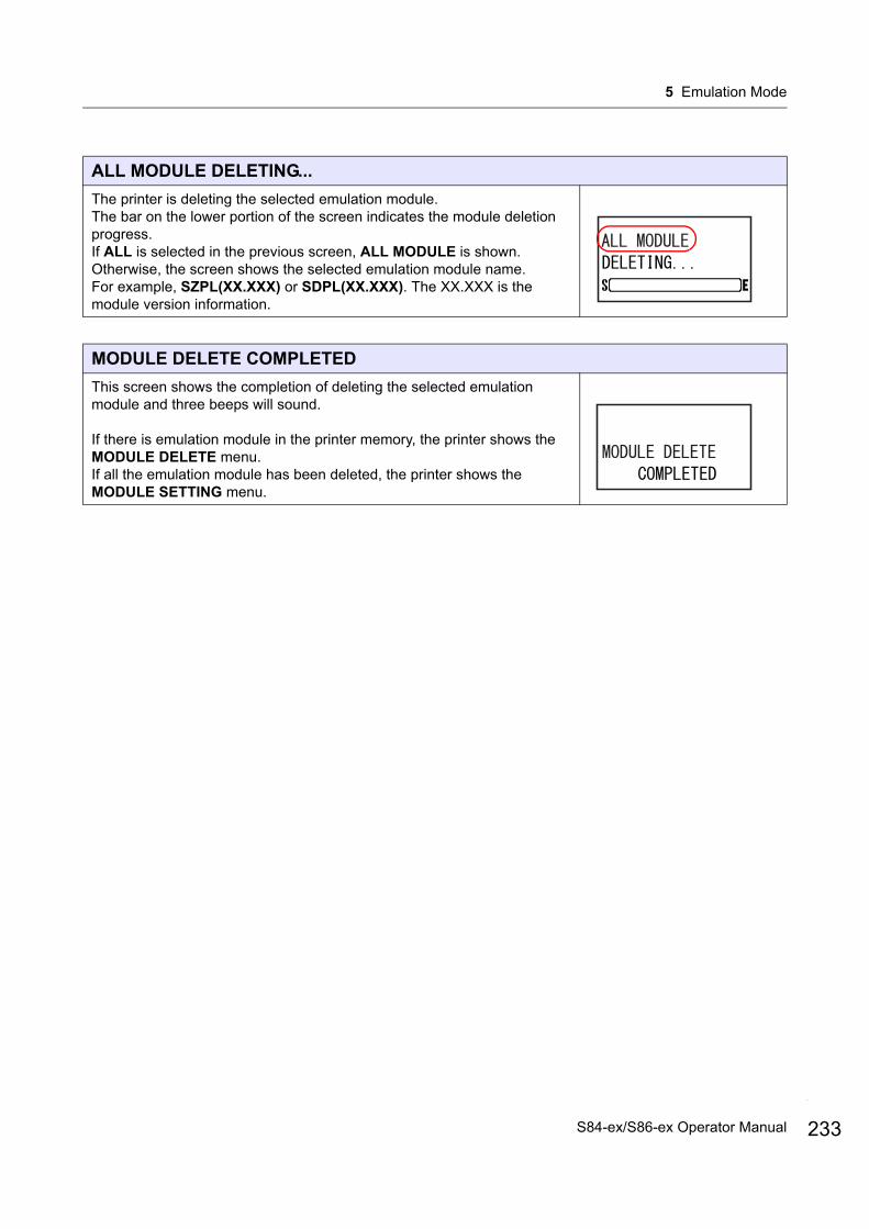
5 Emulation Mode
ALL MODULE DELETING...
The printer is deleting the selected emulation module.The bar on the lower portion of the screen indicates the module deletion progress.If ALL is selected in the previous screen, ALL MODULE is shown. Otherwise, the screen shows the selected emulation module name.For example, SZPL(XX.XXX) or SDPL(XX.XXX). The XX.XXX is the module version information.
MODULE DELETE COMPLETED
This screen shows the completion of deleting the selected emulation module and three beeps will sound.
If there is emulation module in the printer memory, the printer shows the MODULE DELETE menu.If all the emulation module has been deleted, the printer shows the MODULE SETTING menu.
233S84-ex/S86-ex Operator Manual
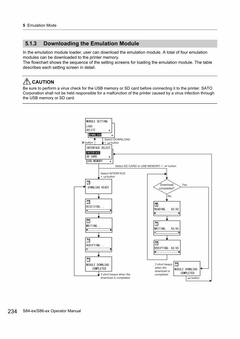
5 Emulation Mode
234
5.1.3 Downloading the Emulation Module
In the emulation module loader, user can download the emulation module. A total of four emulation modules can be downloaded to the printer memory.The flowchart shows the sequence of the setting screens for loading the emulation module. The table describes each setting screen in detail.
CAUTIONBe sure to perform a virus check for the USB memory or SD card before connecting it to the printer. SATO Corporation shall not be held responsible for a malfunction of the printer caused by a virus infection through the USB memory or SD card.
Downloadcompleted?
Yes
No
3 short beeps when the download is completed.
Select DOWNLOAD+ button
Select SD CARD or USB MEMORY + button
button
button
Select INTERFACE+ button
3 short beeps when the download is completed.
S84-ex/S86-ex Operator Manual
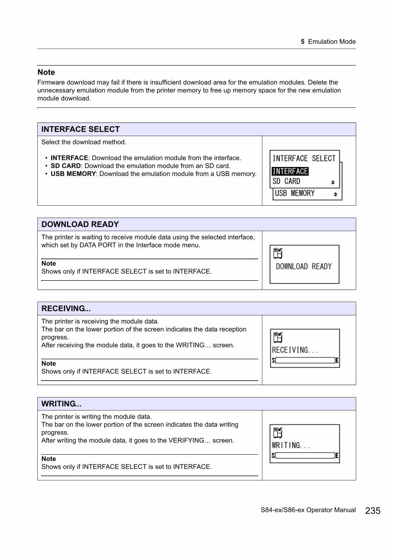
5 Emulation Mode
NoteFirmware download may fail if there is insufficient download area for the emulation modules. Delete the unnecessary emulation module from the printer memory to free up memory space for the new emulation module download.
INTERFACE SELECT
Select the download method.
• INTERFACE: Download the emulation module from the interface.• SD CARD: Download the emulation module from an SD card.• USB MEMORY: Download the emulation module from a USB memory.
DOWNLOAD READY
The printer is waiting to receive module data using the selected interface, which set by DATA PORT in the Interface mode menu.
NoteShows only if INTERFACE SELECT is set to INTERFACE.
RECEIVING...
The printer is receiving the module data.The bar on the lower portion of the screen indicates the data reception progress.After receiving the module data, it goes to the WRITING… screen.
NoteShows only if INTERFACE SELECT is set to INTERFACE.
WRITING...
The printer is writing the module data.The bar on the lower portion of the screen indicates the data writing progress.After writing the module data, it goes to the VERIFYING… screen.
NoteShows only if INTERFACE SELECT is set to INTERFACE.
235S84-ex/S86-ex Operator Manual
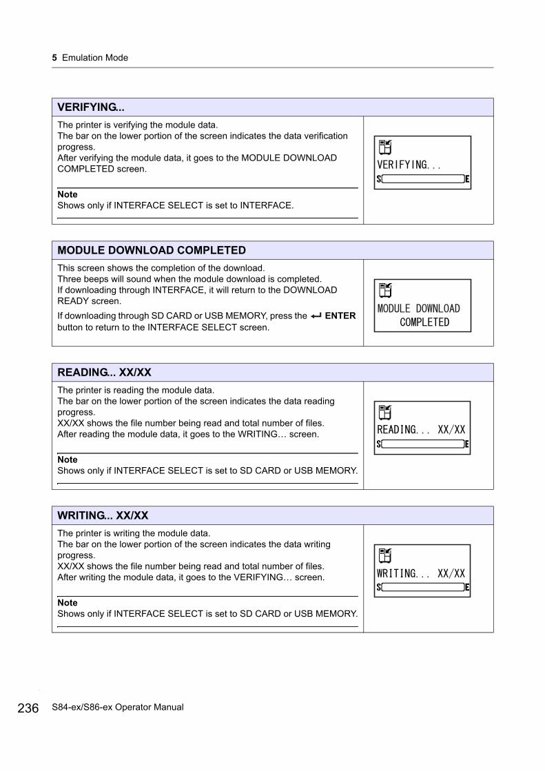
5 Emulation Mode
236
VERIFYING...
The printer is verifying the module data.The bar on the lower portion of the screen indicates the data verification progress.After verifying the module data, it goes to the MODULE DOWNLOAD COMPLETED screen.
NoteShows only if INTERFACE SELECT is set to INTERFACE.
MODULE DOWNLOAD COMPLETED
This screen shows the completion of the download.Three beeps will sound when the module download is completed.If downloading through INTERFACE, it will return to the DOWNLOAD READY screen.
If downloading through SD CARD or USB MEMORY, press the ENTER button to return to the INTERFACE SELECT screen.
READING... XX/XX
The printer is reading the module data.The bar on the lower portion of the screen indicates the data reading progress.XX/XX shows the file number being read and total number of files.After reading the module data, it goes to the WRITING… screen.
NoteShows only if INTERFACE SELECT is set to SD CARD or USB MEMORY.
WRITING... XX/XX
The printer is writing the module data.The bar on the lower portion of the screen indicates the data writing progress.XX/XX shows the file number being read and total number of files.After writing the module data, it goes to the VERIFYING… screen.
NoteShows only if INTERFACE SELECT is set to SD CARD or USB MEMORY.
S84-ex/S86-ex Operator Manual
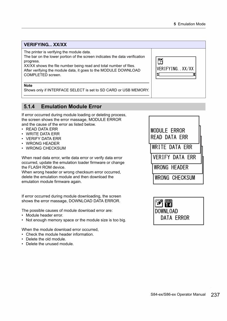
5 Emulation Mode
5.1.4 Emulation Module Error
If error occurred during module loading or deleting process, the screen shows the error massage, MODULE ERROR and the cause of the error as listed below.• READ DATA ERR• WRITE DATA ERR• VERIFY DATA ERR• WRONG HEADER• WRONG CHECKSUM
When read data error, write data error or verify data error occurred, update the emulation loader firmware or change the FLASH ROM device.When wrong header or wrong checksum error occurred, delete the emulation module and then download the emulation module firmware again.
If error occurred during module downloading, the screen shows the error massage, DOWNLOAD DATA ERROR.
The possible causes of module download error are:• Module header error.• Not enough memory space or the module size is too big.
When the module download error occurred, • Check the module header information.• Delete the old module.• Delete the unused module.
VERIFYING... XX/XX
The printer is verifying the module data.The bar on the lower portion of the screen indicates the data verification progress.XX/XX shows the file number being read and total number of files.After verifying the module data, it goes to the MODULE DOWNLOAD COMPLETED screen.
NoteShows only if INTERFACE SELECT is set to SD CARD or USB MEMORY.
237S84-ex/S86-ex Operator Manual
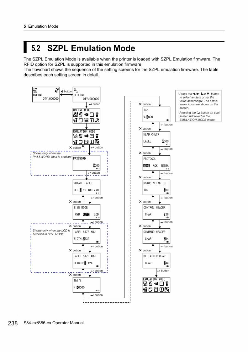
5 Emulation Mode
238
5.2 SZPL Emulation ModeThe SZPL Emulation Mode is available when the printer is loaded with SZPL Emulation firmware. The RFID option for SZPL is supported in this emulation firmware.The flowchart shows the sequence of the setting screens for the SZPL emulation firmware. The table describes each setting screen in detail.
* Press the , , or button to select an item or set the value accordingly. The active arrow icons are shown on the screen.
* Pressing the button on each screen will revert to the EMULATION MODE menu.
button
button
Shows only when the PASSWORD input is enabled
buttonbutton
button
buttonbutton
buttonbutton
buttonbutton
button
buttonbutton
buttonbutton
buttonbutton
buttonbutton
buttonbutton
buttonbutton
buttonbutton
button
Shows only when the LCD is selected in SIZE MODE.
button
S84-ex/S86-ex Operator Manual
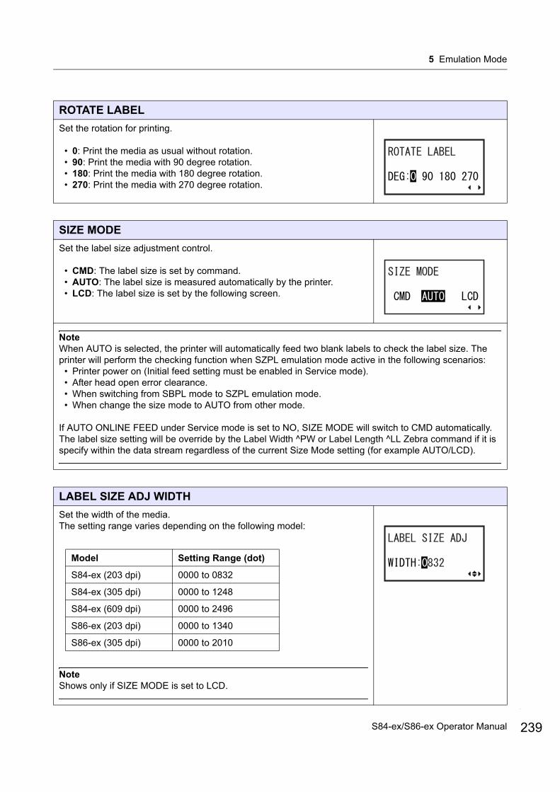
5 Emulation Mode
ROTATE LABEL
Set the rotation for printing.
• 0: Print the media as usual without rotation.• 90: Print the media with 90 degree rotation.• 180: Print the media with 180 degree rotation.• 270: Print the media with 270 degree rotation.
SIZE MODE
Set the label size adjustment control.
• CMD: The label size is set by command.• AUTO: The label size is measured automatically by the printer.• LCD: The label size is set by the following screen.
NoteWhen AUTO is selected, the printer will automatically feed two blank labels to check the label size. The printer will perform the checking function when SZPL emulation mode active in the following scenarios:
• Printer power on (Initial feed setting must be enabled in Service mode).• After head open error clearance.• When switching from SBPL mode to SZPL emulation mode.• When change the size mode to AUTO from other mode.
If AUTO ONLINE FEED under Service mode is set to NO, SIZE MODE will switch to CMD automatically.The label size setting will be override by the Label Width ^PW or Label Length ^LL Zebra command if it is specify within the data stream regardless of the current Size Mode setting (for example AUTO/LCD).
LABEL SIZE ADJ WIDTH
Set the width of the media.The setting range varies depending on the following model:
NoteShows only if SIZE MODE is set to LCD.
Model Setting Range (dot)
S84-ex (203 dpi) 0000 to 0832
S84-ex (305 dpi) 0000 to 1248
S84-ex (609 dpi) 0000 to 2496
S86-ex (203 dpi) 0000 to 1340
S86-ex (305 dpi) 0000 to 2010
239S84-ex/S86-ex Operator Manual
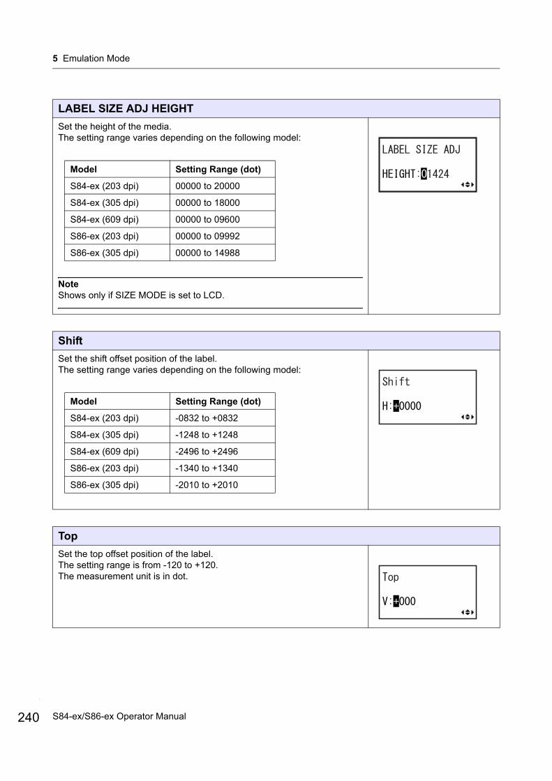
5 Emulation Mode
240
LABEL SIZE ADJ HEIGHT
Set the height of the media.The setting range varies depending on the following model:
NoteShows only if SIZE MODE is set to LCD.
Shift
Set the shift offset position of the label.The setting range varies depending on the following model:
Top
Set the top offset position of the label.The setting range is from -120 to +120.The measurement unit is in dot.
Model Setting Range (dot)
S84-ex (203 dpi) 00000 to 20000
S84-ex (305 dpi) 00000 to 18000
S84-ex (609 dpi) 00000 to 09600
S86-ex (203 dpi) 00000 to 09992
S86-ex (305 dpi) 00000 to 14988
Model Setting Range (dot)
S84-ex (203 dpi) -0832 to +0832
S84-ex (305 dpi) -1248 to +1248
S84-ex (609 dpi) -2496 to +2496
S86-ex (203 dpi) -1340 to +1340
S86-ex (305 dpi) -2010 to +2010
S84-ex/S86-ex Operator Manual

5 Emulation Mode
HEAD CHECK
Specify the number of media between each head check.The setting range is from 0000 to 9999.The head check function is disabled when the value is set to 0000.
PROTOCOL
Set the SZPL communication protocol.
• NONE• ACK• ZEBRA
RS485 NETWK ID
Set the RS485 network ID.The setting range is from 000 to 999.The network is not in used when the ID is set to 000.
CONTROL HEADER
Set the control header character.The setting range is from 000 (00H) to 255 (FFH).
COMMAND HEADER
Set the command header character.The setting range is from 000 (00H) to 255 (FFH).
241S84-ex/S86-ex Operator Manual
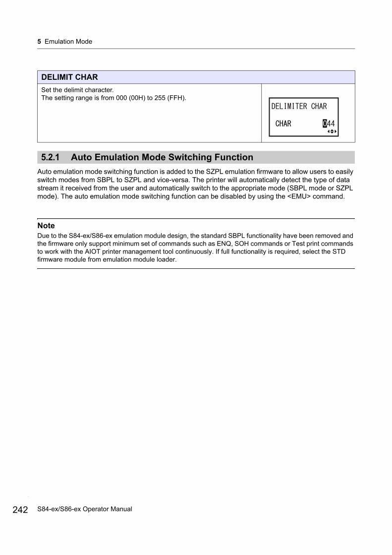
5 Emulation Mode
242
5.2.1 Auto Emulation Mode Switching Function
Auto emulation mode switching function is added to the SZPL emulation firmware to allow users to easily switch modes from SBPL to SZPL and vice-versa. The printer will automatically detect the type of data stream it received from the user and automatically switch to the appropriate mode (SBPL mode or SZPL mode). The auto emulation mode switching function can be disabled by using the <EMU> command.
NoteDue to the S84-ex/S86-ex emulation module design, the standard SBPL functionality have been removed and the firmware only support minimum set of commands such as ENQ, SOH commands or Test print commands to work with the AIOT printer management tool continuously. If full functionality is required, select the STD firmware module from emulation module loader.
DELIMIT CHAR
Set the delimit character.The setting range is from 000 (00H) to 255 (FFH).
S84-ex/S86-ex Operator Manual
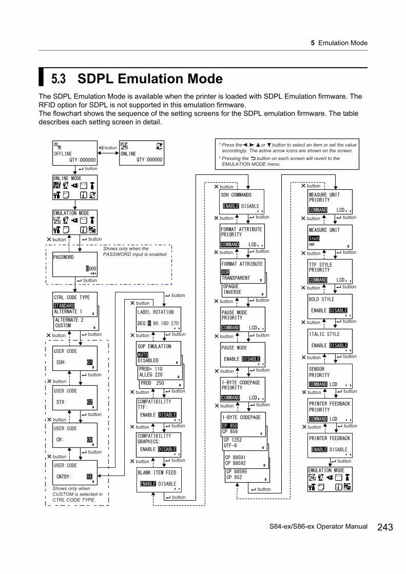
5 Emulation Mode
5.3 SDPL Emulation ModeThe SDPL Emulation Mode is available when the printer is loaded with SDPL Emulation firmware. The RFID option for SDPL is not supported in this emulation firmware.The flowchart shows the sequence of the setting screens for the SDPL emulation firmware. The table describes each setting screen in detail.
* Press the , , or button to select an item or set the value accordingly. The active arrow icons are shown on the screen.
* Pressing the button on each screen will revert to the EMULATION MODE menu.
button
button
Shows only when the PASSWORD input is enabled
buttonbutton
button
buttonbutton
buttonbutton
buttonbutton
button
buttonbutton
buttonbutton
button
Shows only whenCUSTOM is selected inCTRL CODE TYPE.
button
buttonbutton
buttonbutton
buttonbutton
buttonbutton
buttonbutton
buttonbutton
buttonbutton
buttonbutton
buttonbutton
buttonbutton
buttonbutton
buttonbutton
buttonbutton
buttonbutton
buttonbutton
buttonbutton
button
button
buttonbutton
243S84-ex/S86-ex Operator Manual
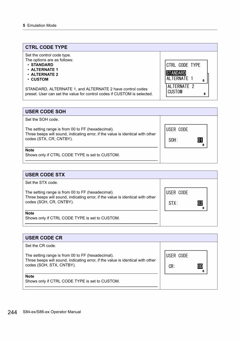
5 Emulation Mode
244
CTRL CODE TYPE
Set the control code type.The options are as follows:
• STANDARD• ALTERNATE 1 • ALTERNATE 2 • CUSTOM
STANDARD, ALTERNATE 1, and ALTERNATE 2 have control codes preset. User can set the value for control codes if CUSTOM is selected.
USER CODE SOH
Set the SOH code.
The setting range is from 00 to FF (hexadecimal).Three beeps will sound, indicating error, if the value is identical with other codes (STX, CR, CNTBY).
NoteShows only if CTRL CODE TYPE is set to CUSTOM.
USER CODE STX
Set the STX code.
The setting range is from 00 to FF (hexadecimal).Three beeps will sound, indicating error, if the value is identical with other codes (SOH, CR, CNTBY).
NoteShows only if CTRL CODE TYPE is set to CUSTOM.
USER CODE CR
Set the CR code.
The setting range is from 00 to FF (hexadecimal).Three beeps will sound, indicating error, if the value is identical with other codes (SOH, STX, CNTBY).
NoteShows only if CTRL CODE TYPE is set to CUSTOM.
S84-ex/S86-ex Operator Manual
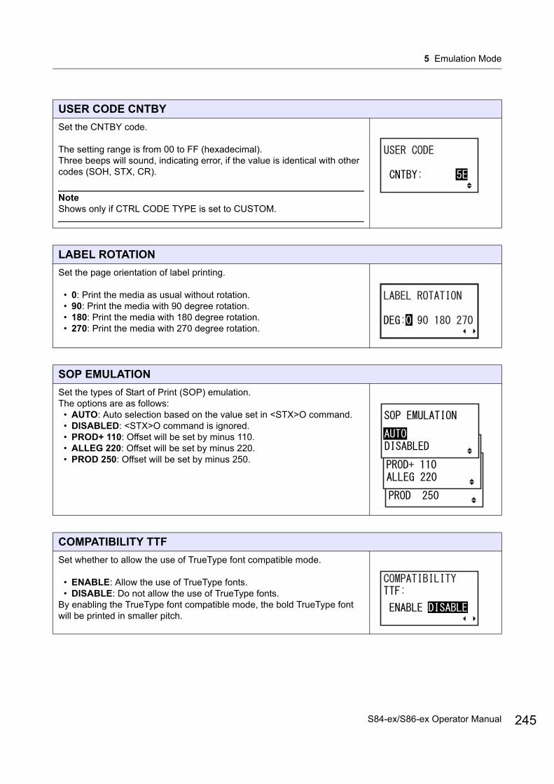
5 Emulation Mode
USER CODE CNTBY
Set the CNTBY code.
The setting range is from 00 to FF (hexadecimal).Three beeps will sound, indicating error, if the value is identical with other codes (SOH, STX, CR).
NoteShows only if CTRL CODE TYPE is set to CUSTOM.
LABEL ROTATION
Set the page orientation of label printing.
• 0: Print the media as usual without rotation.• 90: Print the media with 90 degree rotation.• 180: Print the media with 180 degree rotation.• 270: Print the media with 270 degree rotation.
SOP EMULATION
Set the types of Start of Print (SOP) emulation.The options are as follows:
• AUTO: Auto selection based on the value set in <STX>O command.• DISABLED: <STX>O command is ignored.• PROD+ 110: Offset will be set by minus 110.• ALLEG 220: Offset will be set by minus 220.• PROD 250: Offset will be set by minus 250.
COMPATIBILITY TTF
Set whether to allow the use of TrueType font compatible mode.
• ENABLE: Allow the use of TrueType fonts.• DISABLE: Do not allow the use of TrueType fonts.
By enabling the TrueType font compatible mode, the bold TrueType font will be printed in smaller pitch.
245S84-ex/S86-ex Operator Manual
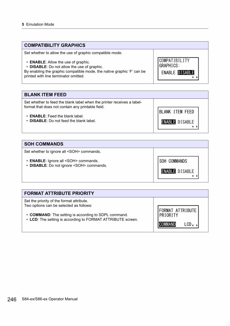
5 Emulation Mode
246
COMPATIBILITY GRAPHICS
Set whether to allow the use of graphic compatible mode.
• ENABLE: Allow the use of graphic.• DISABLE: Do not allow the use of graphic.
By enabling the graphic compatible mode, the native graphic ‘F’ can be printed with line terminator omitted.
BLANK ITEM FEED
Set whether to feed the blank label when the printer receives a label-format that does not contain any printable field.
• ENABLE: Feed the blank label.• DISABLE: Do not feed the blank label.
SOH COMMANDS
Set whether to ignore all <SOH> commands.
• ENABLE: Ignore all <SOH> commands.• DISABLE: Do not ignore <SOH> commands.
FORMAT ATTRIBUTE PRIORITY
Set the priority of the format attribute.Two options can be selected as follows:
• COMMAND: The setting is according to SDPL command.• LCD: The setting is according to FORMAT ATTRIBUTE screen.
S84-ex/S86-ex Operator Manual
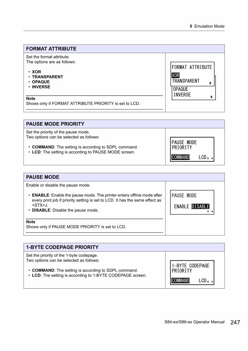
5 Emulation Mode
FORMAT ATTRIBUTE
Set the format attribute.The options are as follows:
• XOR• TRANSPARENT• OPAQUE• INVERSE
NoteShows only if FORMAT ATTRIBUTE PRIORITY is set to LCD.
PAUSE MODE PRIORITY
Set the priority of the pause mode.Two options can be selected as follows:
• COMMAND: The setting is according to SDPL command.• LCD: The setting is according to PAUSE MODE screen.
PAUSE MODE
Enable or disable the pause mode.
• ENABLE: Enable the pause mode. The printer enters offline mode after every print job if priority setting is set to LCD. It has the same effect as <STX>J.
• DISABLE: Disable the pause mode.
NoteShows only if PAUSE MODE PRIORITY is set to LCD.
1-BYTE CODEPAGE PRIORITY
Set the priority of the 1-byte codepage.Two options can be selected as follows:
• COMMAND: The setting is according to SDPL command.• LCD: The setting is according to 1-BYTE CODEPAGE screen.
247S84-ex/S86-ex Operator Manual

5 Emulation Mode
248
1-BYTE CODEPAGE
Select the code page to be used for 1-byte characters from the list.The options are as follows:
• CP 850• CP 858• CP 1252• UTF-8• CP 88591• CP 88592• CP 88595• CP 852
NoteShows only if 1-BYTE CODEPAGE PRIORITY is set to LCD.
MEASURE UNIT PRIORITY
Set the priority of SDPL measure unit.Two options can be selected as follows:
• COMMAND: The setting is according to SDPL command.• LCD: The setting is according to MEASURE UNIT screen.
MEASURE UNIT
Set the measurement unit.
• Inch• mm
NoteShows only if MEASURE UNIT PRIORITY is set to LCD.
TTF STYLE PRIORITY
Set the priority of the TrueType font style.Two options can be selected as follows:
• COMMAND: The setting is according to SDPL command.• LCD: The setting is according to BOLD STYLE screen.
S84-ex/S86-ex Operator Manual

5 Emulation Mode
BOLD STYLE
Set whether or not to print the scalable TrueType font in bold style.
• ENABLE: The scalable TrueType font is always printed in bold style.• DISABLE: The scalable TrueType font is not printed in bold style.
NoteShows only if TTF STYLE PRIORITY is set to LCD.
ITALIC STYLE
Set whether or not to print the scalable TrueType font in italic style.
• ENABLE: The scalable TrueType font is always printed in italic style.• DISABLE: The scalable TrueType font is not printed in italic style.
NoteShows only if TTF STYLE PRIORITY is set to LCD.
SENSOR PRIORITY
Set the priority of SDPL sensor.Two options can be selected as follows:
• COMMAND: The setting is according to SDPL command.• LCD: The setting is according to PRINTER FEEDBACK PRIORITY
screen. Commands <STX>c, <STX>e and <STX>r are ignored.
PRINTER FEEDBACK PRIORITY
Set the priority of printer feedback.Two options can be selected as follows:
• COMMAND: The setting is according to <STX>a command. This command is effective until you restart the printer
• LCD: The setting is according to PRINTER FEEDBACK screen.
249S84-ex/S86-ex Operator Manual

5 Emulation Mode
250
PRINTER FEEDBACK
Set whether to send the printer feedback.Two options can be selected as follows:
• ENABLE: Always send the printer feedback characters to the host.• DISABLE: Do not send the printer feedback characters to the host
except for the power reset signal.
NoteShows only if PRINTER FEEDBACK PRIORITY is set to LCD.
S84-ex/S86-ex Operator Manual
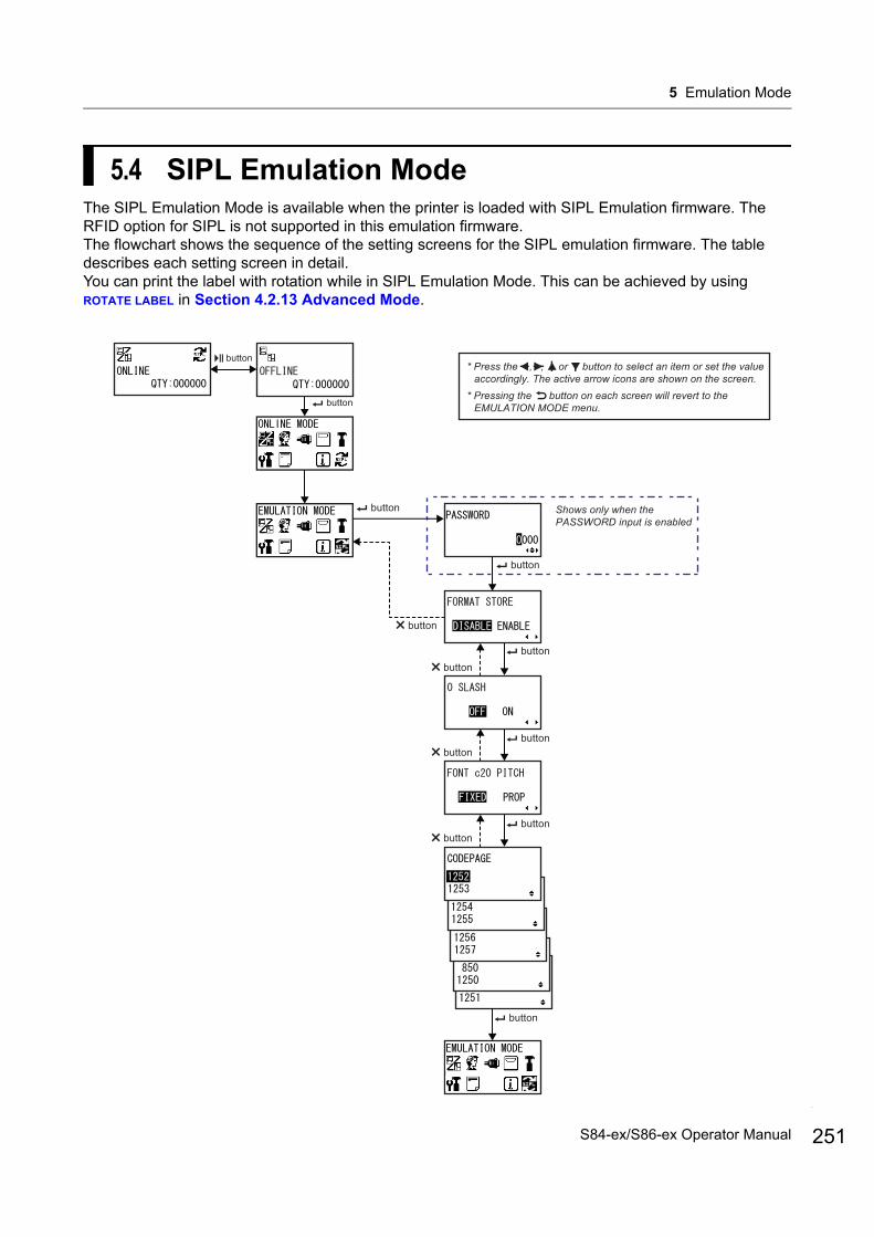
5 Emulation Mode
5.4 SIPL Emulation ModeThe SIPL Emulation Mode is available when the printer is loaded with SIPL Emulation firmware. The RFID option for SIPL is not supported in this emulation firmware.The flowchart shows the sequence of the setting screens for the SIPL emulation firmware. The table describes each setting screen in detail.You can print the label with rotation while in SIPL Emulation Mode. This can be achieved by using ROTATE LABEL in Section 4.2.13 Advanced Mode.
* Press the , , or button to select an item or set the value accordingly. The active arrow icons are shown on the screen.
* Pressing the button on each screen will revert to the EMULATION MODE menu.button
button
Shows only when the PASSWORD input is enabled
button
button
button
buttonbutton
buttonbutton
buttonbutton
button
251S84-ex/S86-ex Operator Manual

5 Emulation Mode
252
FORMAT STORE
Set whether to save the user format data registered at printing in the printer.The options are as follows:
• DISABLE: Do not save the user format data registered at printing in the printer. The user format data remains in the printer memory until the printer is powered off. You need to register a user format again after reboot.
• ENABLE: Save the user format data registered at printing in the printer.
0 SLASH
Set whether to print the number zero (0) with or without a slash (/).The options are as follows:
• OFF: Print zero without a slash.• ON: Print zero with a slash.
FONT c20 PITCH
Set whether to print each character using a fixed pitch or proportional pitch spacing.The options are as follows:
• FIXED: Print all characters with the fixed pitch.• PROP: Print each character with proportional pitch spacing.
CODEPAGE
Select the code page to be used from the list.The options are as follows:
• 1252• 1253• 1254• 1255• 1256• 1257• 850• 1250• 1251
S84-ex/S86-ex Operator Manual

6.1 MaintenanceA dirty print head or platen roller not only affects the print quality but also causes errors. Use a cleaning kit or cleaning sheet to clean the printer regularly.
CAUTION• Do not touch the power switch, connect or disconnect the power cord while your hands are wet. Doing so
could cause an electric shock.• Disconnect the power cord from the AC outlet before you begin cleaning.
The print head and its surroundings are hot after printing. Wait until the printer cools down.• Touching the edge of the print head with your bare hand could cause injury.• Use a cleaning pen, cotton swab or cotton cloth from a cleaning kit to clean. Do not clean with a hard object.
Doing so could cause damage.• Remove the media and ribbon before cleaning.
NoteYou can purchase a cleaning kit or cleaning sheet from a SATO reseller or technical service center.
6 Cleaning and Performing Printer Adjustments
253S84-ex/S86-ex Operator Manual
6 Cleaning and Performing Printer Adjustments
254
6.2 Maintenance of the Print Head and Platen Roller
Maintenance should be performed at the following regular intervals:
• After you print one media roll or print media for one hundred and fifty meters.Use the cleaning kit to clean these parts:
• Print head • Platen roller• Media sensors • Media guide
• After you print six media rolls or print media for nine hundred meters.Use the cleaning sheet to clean these parts:
• Print head • Platen rollerUse the cleaning kit to clean these parts:
• Media guide • Feed roller• Media route • Ribbon route
NoteThe above maintenance intervals are only for reference. Perform the cleaning when necessary.
6.2.1 Maintenance using the Cleaning Kit
The maintenance procedure using the cleaning kit is as follows:
NoteFor details on the cleaning kit, refer to the manual attached to the cleaning kit.
1 Make sure that the printer is in power off mode, then disconnect the power cord from the AC outlet.
2 Open the top cover.
CAUTIONOpen the top cover fully to prevent accidental drop of the cover.
S84-ex/S86-ex Operator Manual
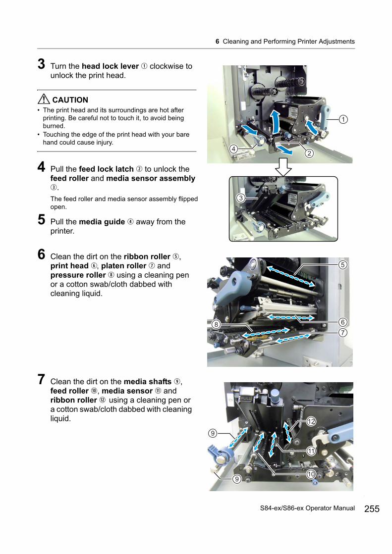
6 Cleaning and Performing Printer Adjustments
3 Turn the head lock lever clockwise to unlock the print head.
CAUTION• The print head and its surroundings are hot after
printing. Be careful not to touch it, to avoid being burned.
• Touching the edge of the print head with your bare hand could cause injury.
4 Pull the feed lock latch to unlock the feed roller and media sensor assembly .The feed roller and media sensor assembly flipped open.
5 Pull the media guide away from the printer.
6 Clean the dirt on the ribbon roller , print head , platen roller and pressure roller using a cleaning pen or a cotton swab/cloth dabbed with cleaning liquid.
7 Clean the dirt on the media shafts , feed roller , media sensor and ribbon roller using a cleaning pen or a cotton swab/cloth dabbed with cleaning liquid.
1
42
3
5
67
8
12
10
9
11
9
255S84-ex/S86-ex Operator Manual
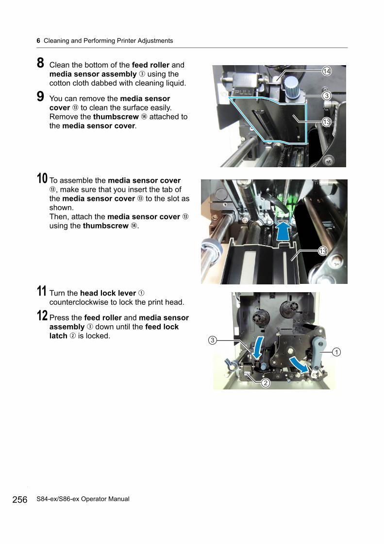
6 Cleaning and Performing Printer Adjustments
256
8 Clean the bottom of the feed roller and media sensor assembly using the cotton cloth dabbed with cleaning liquid.
9 You can remove the media sensor cover to clean the surface easily. Remove the thumbscrew attached to the media sensor cover.
10 To assemble the media sensor cover , make sure that you insert the tab of the media sensor cover to the slot as shown.Then, attach the media sensor cover using the thumbscrew .
11 Turn the head lock lever counterclockwise to lock the print head.
12 Press the feed roller and media sensor assembly down until the feed lock latch is locked.
14
3
13
13
2
3
1
S84-ex/S86-ex Operator Manual

6 Cleaning and Performing Printer Adjustments
6.2.2 Maintenance using the Cleaning Sheet
The maintenance procedure using the cleaning sheet is as follows:
1 Make sure that the printer is in power off mode, then disconnect the power cord from the AC outlet.
2 Open the top cover.
CAUTIONOpen the top cover fully to prevent accidental drop of the cover.
3 Turn the head lock lever clockwise to unlock the print head.
CAUTION• The print head and its surroundings are hot after
printing. Be careful not to touch it, to avoid being burned.
• Touching the edge of the print head with your bare hand could cause injury.
4 Place the cleaning sheet between the print head and the platen roller.
NoteAlign the rough side of the cleaning sheet adjacent to the print head.
1
2
257S84-ex/S86-ex Operator Manual
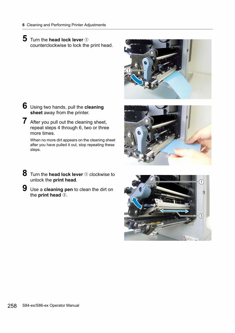
6 Cleaning and Performing Printer Adjustments
258
5 Turn the head lock lever counterclockwise to lock the print head.
6 Using two hands, pull the cleaning sheet away from the printer.
7 After you pull out the cleaning sheet, repeat steps 4 through 6, two or three more times.When no more dirt appears on the cleaning sheet after you have pulled it out, stop repeating these steps.
8 Turn the head lock lever clockwise to unlock the print head.
9 Use a cleaning pen to clean the dirt on the print head .
1
1
3
S84-ex/S86-ex Operator Manual

6 Cleaning and Performing Printer Adjustments
6.3 Adjusting the Base Reference Point
6.3.1 About the Base Reference Point
The base reference point is the point at which one determines the print position and stop/dispensing position.The base reference point differs depending on the operation mode or media sensor you use.
Gap LabelI-mark Label
Continuous Mode
Gap LabelI-mark Label
Print and dispensing position
Dispenser Mode
Print and dispensing position
Print and stop position Print and
stop position
Feed
dire
ctio
n
Feed
dire
ctio
n
Feed
dire
ctio
n
Feed
dire
ctio
n
259S84-ex/S86-ex Operator Manual

6 Cleaning and Performing Printer Adjustments
260
6.3.2 Adjusting the Print Position
Print position is adjustable within the range of +3.75 mm to -3.75 mm (+0.15” to -0.15”) in the adjustment mode described above. The shift experienced by the media, ribbon or print layout can be offset with the adjustment of the pitch position.
NoteThe above base reference point (print position) will be the stop position when the sensor type is set to Gap sensor.
Adjust the print position using the following procedure:
1 Make sure that the printer is in online mode or offline mode.
2 Press the and buttons for one second to enter the adjustment mode.PITCH POSITION shows on the screen.
Adjustment Location Adjustment Range
Adjustment Mode: Pitch Position +3.75 mm to -3.75 mm(+0.15” to -0.15”)
-3.75 mm (-0.15”) ~ +3.75 mm (+0.15”)
Media feed direction
Print position (Print head)
Adjustment for“+” value
No adjustment
Adjustment for“-” value
Gap sensor
S84-ex/S86-ex Operator Manual

6 Cleaning and Performing Printer Adjustments
3 Change the setting value. Press the / buttons to set the desired value.Set the offset value with ‘+’ to move the print position opposite the feed direction, and value with ‘-’ to move the print position in the feed direction.The setting value is adjustable by 0.25 mm (0.01”) regardless of print resolution.The setting range is from -3.75 mm (-0.15”) to +3.75 mm (+0.15”).
4 Press the ENTER button to save the setting and go to the next adjustment screen.
6.3.3 Adjusting the Media Stop Position
The stop position for options (such as Dispenser) is adjustable within the range of +3.75 mm to -3.75 mm (+0.15” to -0.15”) in the adjustment mode described above.
NoteThe above dispensing position for printing indicates the label stop position when the media sensor is set to Gap sensor.
Adjustment Location Adjustment Range
Adjustment Mode: Offset Position +3.75 mm to -3.75 mm(+0.15” to -0.15”)
-3.75 mm (-0.15”) ~ +3.75 mm (+0.15”)
Media feed direction
Print position (Print head)
Adjustment for“+” value
No adjustment
Adjustment for“-” value
Dispensing position
261S84-ex/S86-ex Operator Manual
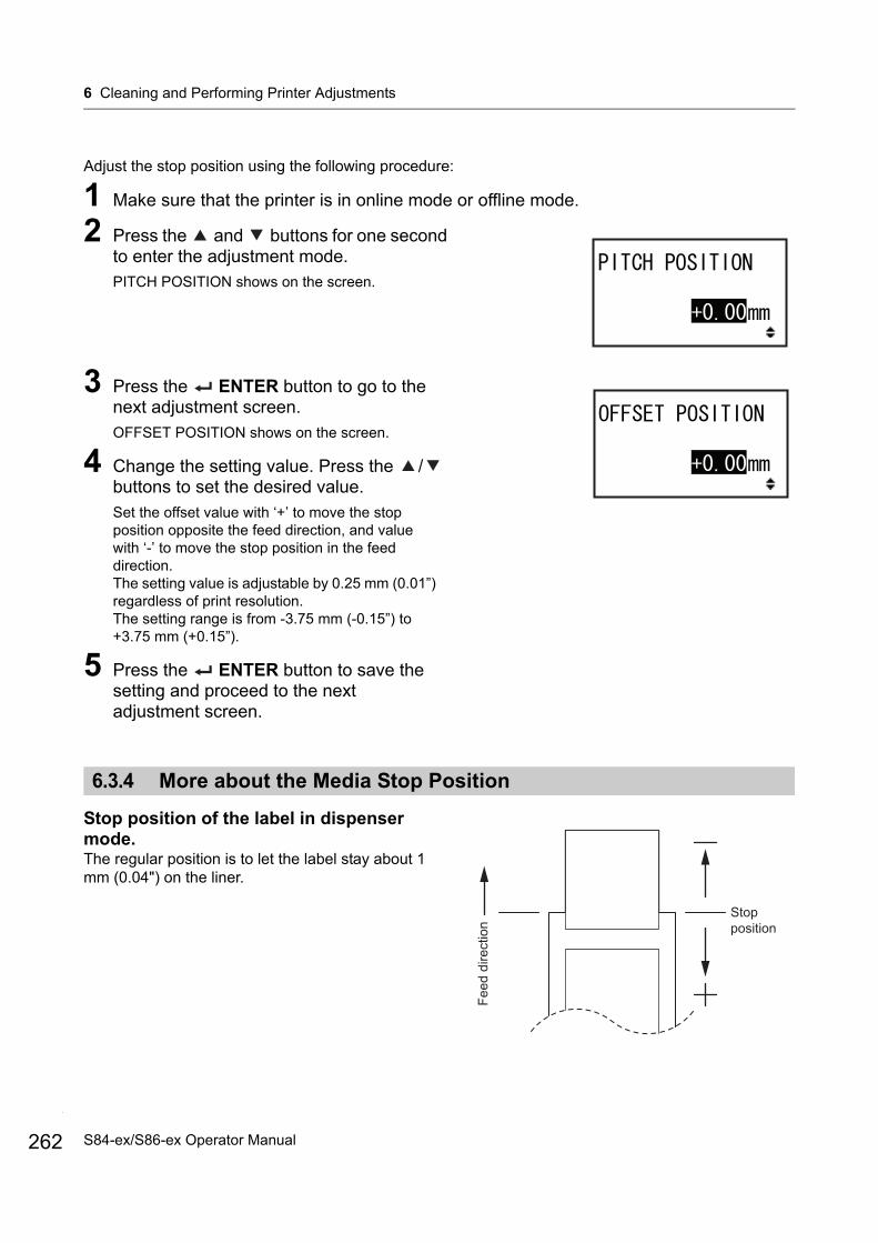
6 Cleaning and Performing Printer Adjustments
262
Adjust the stop position using the following procedure:
1 Make sure that the printer is in online mode or offline mode.
2 Press the and buttons for one second to enter the adjustment mode.PITCH POSITION shows on the screen.
3 Press the ENTER button to go to the next adjustment screen.OFFSET POSITION shows on the screen.
4 Change the setting value. Press the / buttons to set the desired value.Set the offset value with ‘+’ to move the stop position opposite the feed direction, and value with ‘-’ to move the stop position in the feed direction.The setting value is adjustable by 0.25 mm (0.01”) regardless of print resolution.The setting range is from -3.75 mm (-0.15”) to +3.75 mm (+0.15”).
5 Press the ENTER button to save the setting and proceed to the next adjustment screen.
6.3.4 More about the Media Stop Position
Stop position of the label in dispenser mode.The regular position is to let the label stay about 1 mm (0.04") on the liner.
Stop position
Feed
dire
ctio
n
S84-ex/S86-ex Operator Manual
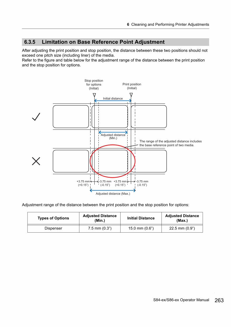
6 Cleaning and Performing Printer Adjustments
6.3.5 Limitation on Base Reference Point Adjustment
After adjusting the print position and stop position, the distance between these two positions should not exceed one pitch size (including liner) of the media.Refer to the figure and table below for the adjustment range of the distance between the print position and the stop position for options.
Adjustment range of the distance between the print position and the stop position for options:
Types of OptionsAdjusted Distance
(Min.)Initial Distance
Adjusted Distance (Max.)
Dispenser 7.5 mm (0.3”) 15.0 mm (0.6”) 22.5 mm (0.9”)
Print position(Initial)
Stop position for options
(Initial)
+3.75 mm(+0.15”)
Initial distance
-3.75 mm(-0.15”)
+3.75 mm(+0.15”)
-3.75 mm(-0.15”)
Adjusted distance (Max.)
The range of the adjusted distance includes the base reference point of two media.
Adjusted distance(Min.)
263S84-ex/S86-ex Operator Manual
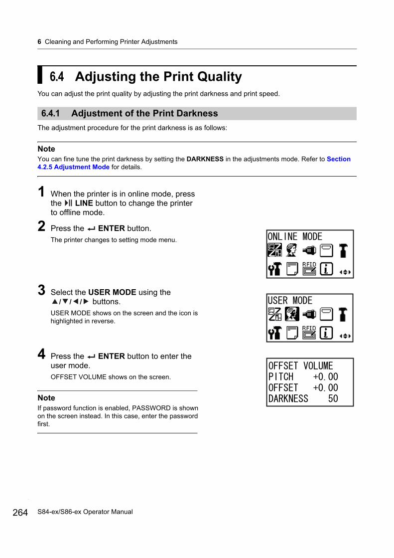
6 Cleaning and Performing Printer Adjustments
264
6.4 Adjusting the Print QualityYou can adjust the print quality by adjusting the print darkness and print speed.
6.4.1 Adjustment of the Print Darkness
The adjustment procedure for the print darkness is as follows:
NoteYou can fine tune the print darkness by setting the DARKNESS in the adjustments mode. Refer to Section 4.2.5 Adjustment Mode for details.
1 When the printer is in online mode, press the LINE button to change the printer to offline mode.
2 Press the ENTER button.The printer changes to setting mode menu.
3 Select the USER MODE using the / / / buttons.
USER MODE shows on the screen and the icon is highlighted in reverse.
4 Press the ENTER button to enter the user mode.OFFSET VOLUME shows on the screen.
NoteIf password function is enabled, PASSWORD is shown on the screen instead. In this case, enter the password first.
S84-ex/S86-ex Operator Manual
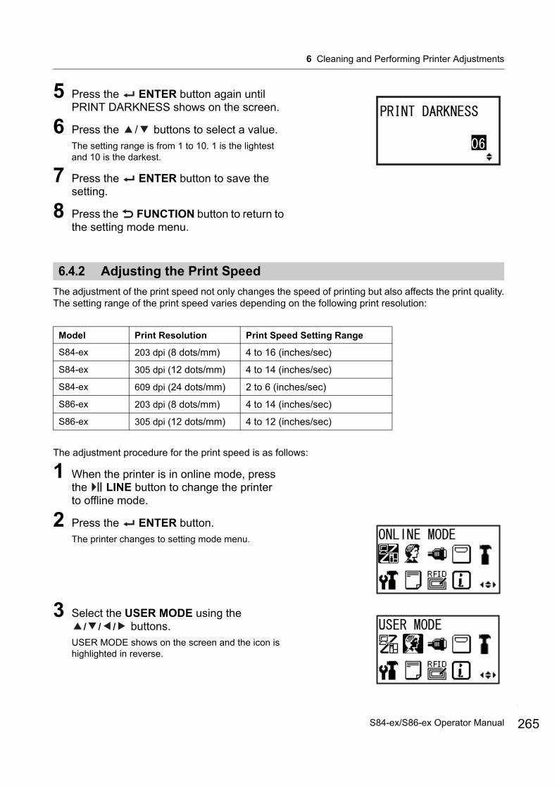
6 Cleaning and Performing Printer Adjustments
5 Press the ENTER button again until PRINT DARKNESS shows on the screen.
6 Press the / buttons to select a value.The setting range is from 1 to 10. 1 is the lightest and 10 is the darkest.
7 Press the ENTER button to save the setting.
8 Press the FUNCTION button to return to the setting mode menu.
6.4.2 Adjusting the Print Speed
The adjustment of the print speed not only changes the speed of printing but also affects the print quality.The setting range of the print speed varies depending on the following print resolution:
The adjustment procedure for the print speed is as follows:
1 When the printer is in online mode, press the LINE button to change the printer to offline mode.
2 Press the ENTER button.The printer changes to setting mode menu.
3 Select the USER MODE using the / / / buttons.
USER MODE shows on the screen and the icon is highlighted in reverse.
Model Print Resolution Print Speed Setting Range
S84-ex 203 dpi (8 dots/mm) 4 to 16 (inches/sec)
S84-ex 305 dpi (12 dots/mm) 4 to 14 (inches/sec)
S84-ex 609 dpi (24 dots/mm) 2 to 6 (inches/sec)
S86-ex 203 dpi (8 dots/mm) 4 to 14 (inches/sec)
S86-ex 305 dpi (12 dots/mm) 4 to 12 (inches/sec)
265S84-ex/S86-ex Operator Manual
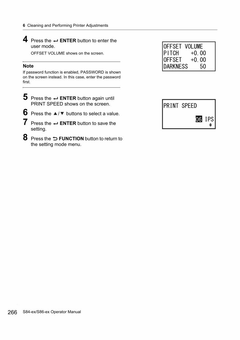
6 Cleaning and Performing Printer Adjustments
266
4 Press the ENTER button to enter the user mode.OFFSET VOLUME shows on the screen.
NoteIf password function is enabled, PASSWORD is shown on the screen instead. In this case, enter the password first.
5 Press the ENTER button again until PRINT SPEED shows on the screen.
6 Press the / buttons to select a value.
7 Press the ENTER button to save the setting.
8 Press the FUNCTION button to return to the setting mode menu.
S84-ex/S86-ex Operator Manual
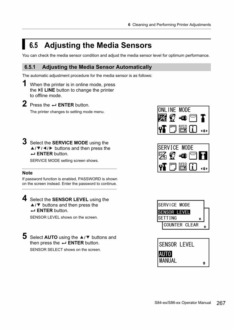
6 Cleaning and Performing Printer Adjustments
6.5 Adjusting the Media SensorsYou can check the media sensor condition and adjust the media sensor level for optimum performance.
6.5.1 Adjusting the Media Sensor Automatically
The automatic adjustment procedure for the media sensor is as follows:
1 When the printer is in online mode, press the LINE button to change the printer to offline mode.
2 Press the ENTER button.The printer changes to setting mode menu.
3 Select the SERVICE MODE using the / / / buttons and then press the ENTER button.
SERVICE MODE setting screen shows.
NoteIf password function is enabled, PASSWORD is shown on the screen instead. Enter the password to continue.
4 Select the SENSOR LEVEL using the / buttons and then press the ENTER button.
SENSOR LEVEL shows on the screen.
5 Select AUTO using the / buttons and then press the ENTER button.SENSOR SELECT shows on the screen.
267S84-ex/S86-ex Operator Manual

6 Cleaning and Performing Printer Adjustments
268
6 Press the / buttons to select the type of sensor to be adjusted and then press the
ENTER button.
The instruction of placing the media shows.
7 Open the top cover and unlock the media feed and media sensor assembly .
8 Place the media/liner on the media sensor.To adjust the I-mark sensor, place the white area of media under the media sensor.To adjust the gap sensor, peel off the label and place the liner under the media sensor.
9 Press the media feed and media sensor assembly down to lock it.To get the correct adjustment result, perform the adjustment after you have closed the media sensor assembly.
10 Press the ENTER button to start the sensor adjustment.
When I-MARK is selected
When GAP is selected
1
2
Media sensors area
S84-ex/S86-ex Operator Manual
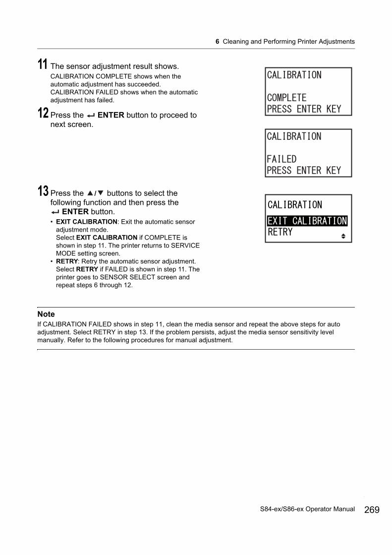
6 Cleaning and Performing Printer Adjustments
11 The sensor adjustment result shows.CALIBRATION COMPLETE shows when the automatic adjustment has succeeded.CALIBRATION FAILED shows when the automatic adjustment has failed.
12 Press the ENTER button to proceed to next screen.
13 Press the / buttons to select the following function and then press the
ENTER button.• EXIT CALIBRATION: Exit the automatic sensor
adjustment mode.Select EXIT CALIBRATION if COMPLETE is shown in step 11. The printer returns to SERVICE MODE setting screen.
• RETRY: Retry the automatic sensor adjustment.Select RETRY if FAILED is shown in step 11. The printer goes to SENSOR SELECT screen and repeat steps 6 through 12.
NoteIf CALIBRATION FAILED shows in step 11, clean the media sensor and repeat the above steps for auto adjustment. Select RETRY in step 13. If the problem persists, adjust the media sensor sensitivity level manually. Refer to the following procedures for manual adjustment.
269S84-ex/S86-ex Operator Manual

6 Cleaning and Performing Printer Adjustments
270
6.5.2 Adjusting the I-mark Sensor Level Manually
The adjustment procedure for the I-mark sensor level is as follows:
1 Go to the SENSOR LEVEL setting screen of SERVICE MODE.Perform steps 1 through 4 of Section 6.5.1 Adjusting the Media Sensor Automatically.
2 Select MANUAL using the / buttons and then press the ENTER button.The light emission level adjustment of the I-mark sensor is shown.
3 On the SENSOR LEVEL I-MARK(E) screen, press the / buttons to set ADJUST LEVEL to 2 and then press the
ENTER button.The adjustment range of ADJUST LEVEL is from 0 to 3.We recommend using the initial value which is 2.The light reception level adjustment of the I-mark sensor is shown.
First, adjust the “Low” reception level (voltage) of the I-mark sensor.
4 Open the top cover and unlock the media feed and media sensor assembly .
5 Physically place the media , with the portion without the I-mark resting over the I-mark sensor.
6 Press the media feed and media sensor assembly down to lock it.To get the correct adjustment result, close the media sensor assembly before performing the adjustment.
1
2 I-mark sensor
S84-ex/S86-ex Operator Manual
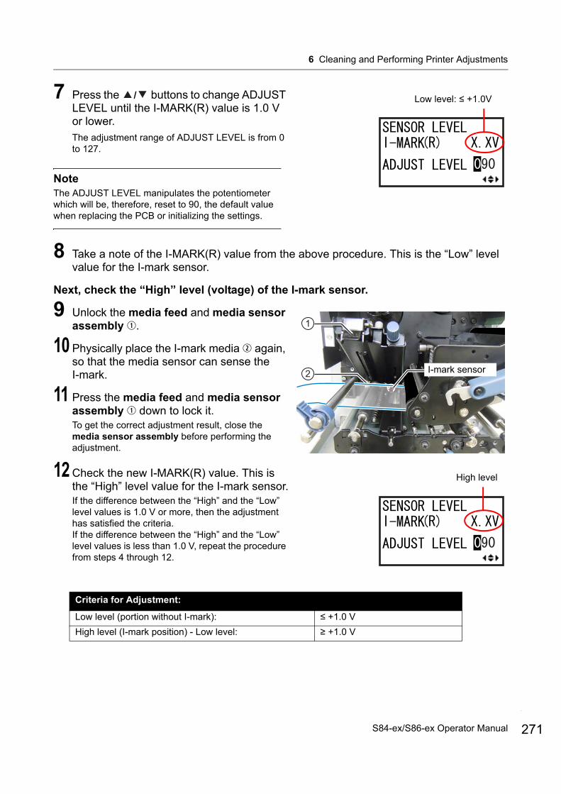
6 Cleaning and Performing Printer Adjustments
7 Press the / buttons to change ADJUST LEVEL until the I-MARK(R) value is 1.0 V or lower.The adjustment range of ADJUST LEVEL is from 0 to 127.
NoteThe ADJUST LEVEL manipulates the potentiometer which will be, therefore, reset to 90, the default value when replacing the PCB or initializing the settings.
8 Take a note of the I-MARK(R) value from the above procedure. This is the “Low” level value for the I-mark sensor.
Next, check the “High” level (voltage) of the I-mark sensor.
9 Unlock the media feed and media sensor assembly .
10 Physically place the I-mark media again, so that the media sensor can sense the I-mark.
11 Press the media feed and media sensor assembly down to lock it.To get the correct adjustment result, close the media sensor assembly before performing the adjustment.
12 Check the new I-MARK(R) value. This is the “High” level value for the I-mark sensor.If the difference between the “High” and the “Low” level values is 1.0 V or more, then the adjustment has satisfied the criteria.If the difference between the “High” and the “Low” level values is less than 1.0 V, repeat the procedure from steps 4 through 12.
Criteria for Adjustment:
Low level (portion without I-mark): ≤ +1.0 V
High level (I-mark position) - Low level: ≥ +1.0 V
Low level: ≤ +1.0V
1
2 I-mark sensor
High level
271S84-ex/S86-ex Operator Manual

6 Cleaning and Performing Printer Adjustments
272
13 Press the ENTER button to confirm the setting and proceed to slice level adjustment screen.
NoteIf you are having difficulties in adjusting the sensor level properly, clean the media sensor portion. If the problem persists, contact your SATO reseller or technical support center to replace the media sensor.
14 Press the / buttons to change the SLICE LEVEL and then press the
ENTER button.The slice level can be set to 0.0 V, or from 0.3 V to 2.9 V. (adjustable in increments of 0.1 V)If you set the SLICE LEVEL to 0.0 V, the printer sets the slice level automatically.
15 If you completed with I-mark sensor level adjustment, press the FUNCTION button to return to the SERVICE MODE menu. Otherwise, continue with the Gap sensor level adjustment.Proceed to step 2 of Section 6.5.3 Adjusting the Gap Sensor Level Manually.
S84-ex/S86-ex Operator Manual

6 Cleaning and Performing Printer Adjustments
6.5.3 Adjusting the Gap Sensor Level Manually
The adjustment procedure for the Gap sensor level is as follows:
1 Continue the procedure from step 15 of Section 6.5.2 Adjusting the I-mark Sensor Level Manually.If you only want to adjust the Gap sensor level, after selecting MANUAL in SENSOR LEVEL screen, press ENTER button repeatedly until SENSOR LEVEL GAP(E) screen is shown.
2 On the SENSOR LEVEL GAP(E) screen, press the / buttons to set ADJUST LEVEL to 2 and then press the ENTER button.The adjustment range of ADJUST LEVEL is from 0 to 3.We recommend using the initial value which is 2.The light reception level adjustment of the Gap sensor is shown.
First, adjust the “Low” reception level (voltage) of the Gap sensor.
3 Open the top cover and unlock the media feed and media sensor assembly .
4 Physically place the liner without the label resting over the Gap sensor.
5 Press the media feed and media sensor assembly down to lock it.To get the correct adjustment result, close the media sensor assembly before performing the adjustment.
6 Press the / buttons to change ADJUST LEVEL until the GAP(R) value is 1.0 V or lower.The adjustment range of ADJUST LEVEL is from 0 to 127.
NoteThe ADJUST LEVEL manipulates the potentiometer which will be, therefore, reset to 90, the default value when replacing the PCB or initializing the settings.
1
2
Gap sensors area
Low level: ≤ +1.0V
273S84-ex/S86-ex Operator Manual
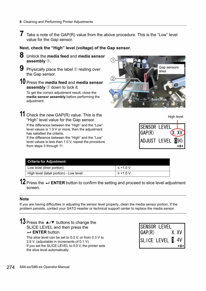
6 Cleaning and Performing Printer Adjustments
274
7 Take a note of the GAP(R) value from the above procedure. This is the “Low” level value for the Gap sensor.
Next, check the “High” level (voltage) of the Gap sensor.
8 Unlock the media feed and media sensor assembly .
9 Physically place the label resting over the Gap sensor.
10 Press the media feed and media sensor assembly down to lock it.To get the correct adjustment result, close the media sensor assembly before performing the adjustment.
11 Check the new GAP(R) value. This is the “High” level value for the Gap sensor.If the difference between the “High” and the “Low” level values is 1.0 V or more, then the adjustment has satisfied the criteria.If the difference between the “High” and the “Low” level values is less than 1.0 V, repeat the procedure from steps 3 through 11.
12 Press the ENTER button to confirm the setting and proceed to slice level adjustment screen.
NoteIf you are having difficulties in adjusting the sensor level properly, clean the media sensor portion. If the problem persists, contact your SATO reseller or technical support center to replace the media sensor.
13 Press the / buttons to change the SLICE LEVEL and then press the
ENTER button.The slice level can be set to 0.0 V, or from 0.3 V to 2.9 V. (adjustable in increments of 0.1 V)If you set the SLICE LEVEL to 0.0 V, the printer sets the slice level automatically.
Criteria for Adjustment:
Low level (liner portion): ≤ +1.0 V
High level (label portion) - Low level: ≥ +1.0 V
1
Gap sensors area
2
High level
S84-ex/S86-ex Operator Manual

6 Cleaning and Performing Printer Adjustments
6.5.4 Adjusting the Paper End Sensor
This printer uses an I-mark sensor to sense the Paper end error.The checking and adjustment procedures for the Paper end (I-mark) sensor level are as follows:
1 Go to the SENSOR LEVEL I-MARK(R) setting screen of SERVICE MODE.
First, check the I-MARK(R) value (voltage) of the Paper end (I-mark) sensor when the liner is placed on the sensor.
2 Open the top cover and unlock the media feed and media sensor assembly .
3 Physically place the liner without the label resting over the I-mark sensor.
4 Press the media feed and media sensor assembly down to lock it.To get the correct adjustment result, close the media sensor assembly before performing the adjustment.
5 Check if the I-MARK(R) value is 2.0 V or lower.If not, change ADJUST LEVEL using the / buttons until the I-MARK(R) value is 2.0 V or lower.
1
2 I-mark sensor
I-MARK(R) level: ≤ +2.0V
275S84-ex/S86-ex Operator Manual
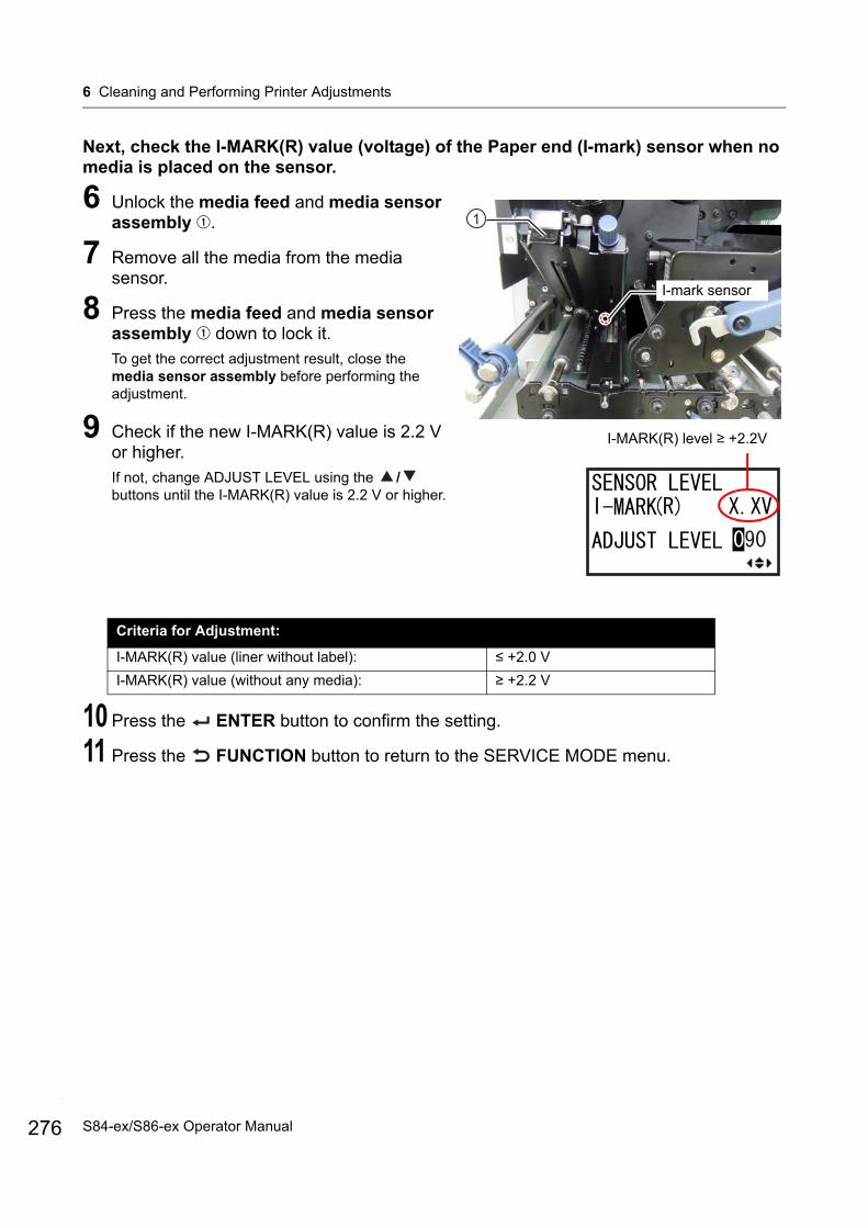
6 Cleaning and Performing Printer Adjustments
276
Next, check the I-MARK(R) value (voltage) of the Paper end (I-mark) sensor when no media is placed on the sensor.
6 Unlock the media feed and media sensor assembly .
7 Remove all the media from the media sensor.
8 Press the media feed and media sensor assembly down to lock it.To get the correct adjustment result, close the media sensor assembly before performing the adjustment.
9 Check if the new I-MARK(R) value is 2.2 V or higher. If not, change ADJUST LEVEL using the / buttons until the I-MARK(R) value is 2.2 V or higher.
10 Press the ENTER button to confirm the setting.
11 Press the FUNCTION button to return to the SERVICE MODE menu.
Criteria for Adjustment:
I-MARK(R) value (liner without label): ≤ +2.0 V
I-MARK(R) value (without any media): ≥ +2.2 V
1
I-mark sensor
I-MARK(R) level ≥ +2.2V
S84-ex/S86-ex Operator Manual
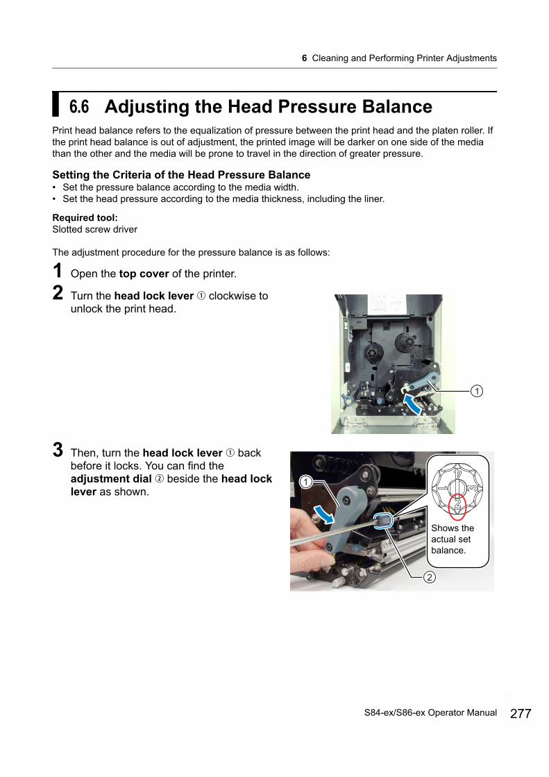
6 Cleaning and Performing Printer Adjustments
6.6 Adjusting the Head Pressure BalancePrint head balance refers to the equalization of pressure between the print head and the platen roller. If the print head balance is out of adjustment, the printed image will be darker on one side of the media than the other and the media will be prone to travel in the direction of greater pressure.
Setting the Criteria of the Head Pressure Balance• Set the pressure balance according to the media width.• Set the head pressure according to the media thickness, including the liner.
Required tool:Slotted screw driver
The adjustment procedure for the pressure balance is as follows:
1 Open the top cover of the printer.
2 Turn the head lock lever clockwise to unlock the print head.
3 Then, turn the head lock lever back before it locks. You can find the adjustment dial beside the head lock lever as shown.
1
2
1
Shows the actual set balance.
277S84-ex/S86-ex Operator Manual

6 Cleaning and Performing Printer Adjustments
278
4 Use the slotted screw driver to turn the adjustment dial . Set the pressure balance according to the media width and media thickness.
Note• The factory default setting is .• The thickness of the media includes the liner.
Media Thickness0.05 to 0.20 mm
(0.002” to 0.0079”)Thin paper/normal label, etc.
0.20 to 0.31 mm(0.0079” to 0.30122”)Thick paper/tag, etc.
Media Width
S84-ex30 to 128 mm (1.18” to 5.04”)
10 to <30 mm (0.39” to <1.18”)
30 to 128 mm (1.18” to 5.04”)
10 to <30 mm (0.39” to <1.18”)
S86-ex80 to 177 mm (3.15” to 6.97”)
51 to <80 mm (2.01” to <3.15”)
80 to 177 mm (3.15” to 6.97”)
51 to <80 mm (2.01” to <3.15”)
Pressure Balance Adjustment Dial
S84-ex/S86-ex Operator Manual

6 Cleaning and Performing Printer Adjustments
6.7 Adjusting the Head Position
6.7.1 Left - Right Pressure Balance Setting
Required tool:Phillips screwdriver
The adjustment procedure for the pressure balance is as follows:
1 Open the top cover of the printer.
2 Make sure that the head lock lever is in the lock position.If it is not locked, turn the head lock lever counterclockwise to lock the print head.
3 Locate the adjust collar on the side of the print head assembly.
4 Loosen the screw attached to the adjust collar .Do not remove the screw.
5 Rotate the adjust collar to adjust the head pressure balance. • Rotate the adjust collar counterclockwise to
increase the head pressure on the frame side.• Rotate the adjust collar clockwise to increase the
head pressure on the opposite side.
NoteIf the printer orientation is opposite from the photo, the adjustment direction is reversed.
6 Hold the adjust collar in the set position and tighten the screw .
1
2
1
279S84-ex/S86-ex Operator Manual

6 Cleaning and Performing Printer Adjustments
280
6.7.2 Front - Rear Head Alignment
Required tools:• Phillips screwdriver • Slotted screwdriver
The adjustment procedure for the head alignment is as follows:
1 Open the top cover of the printer.
2 Make sure that the head lock lever is in the lock position.If it is not locked, turn the head lock lever counterclockwise to lock the print head.
3 Locate two screws from the front of the print head assembly.
4 Loosen two screws using the Phillips screwdriver.Do not remove the screws.
5 Insert the slotted screwdriver into the regulation apertures on the left and right sides. Adjust the head position by turning the slotted screwdriver in the relevant direction.• Direction A: Print head position moves forward. • Direction B: Print head position moves backward.
6 Tighten two screws .
1 12 2
B
A
B
A
S84-ex/S86-ex Operator Manual
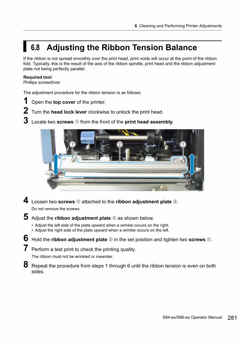
6 Cleaning and Performing Printer Adjustments
6.8 Adjusting the Ribbon Tension BalanceIf the ribbon is not spread smoothly over the print head, print voids will occur at the point of the ribbon fold. Typically, this is the result of the axis of the ribbon spindle, print head and the ribbon adjustment plate not being perfectly parallel.
Required tool:Phillips screwdriver
The adjustment procedure for the ribbon tension is as follows:
1 Open the top cover of the printer.
2 Turn the head lock lever clockwise to unlock the print head.
3 Locate two screws from the front of the print head assembly.
4 Loosen two screws attached to the ribbon adjustment plate .Do not remove the screws.
5 Adjust the ribbon adjustment plate as shown below.• Adjust the left side of the plate upward when a wrinkle occurs on the right.• Adjust the right side of the plate upward when a wrinkle occurs on the left.
6 Hold the ribbon adjustment plate in the set position and tighten two screws .
7 Perform a test print to check the printing quality.The ribbon must not be wrinkled or meander.
8 Repeat the procedure from steps 1 through 6 until the ribbon tension is even on both sides.
21 1
281S84-ex/S86-ex Operator Manual
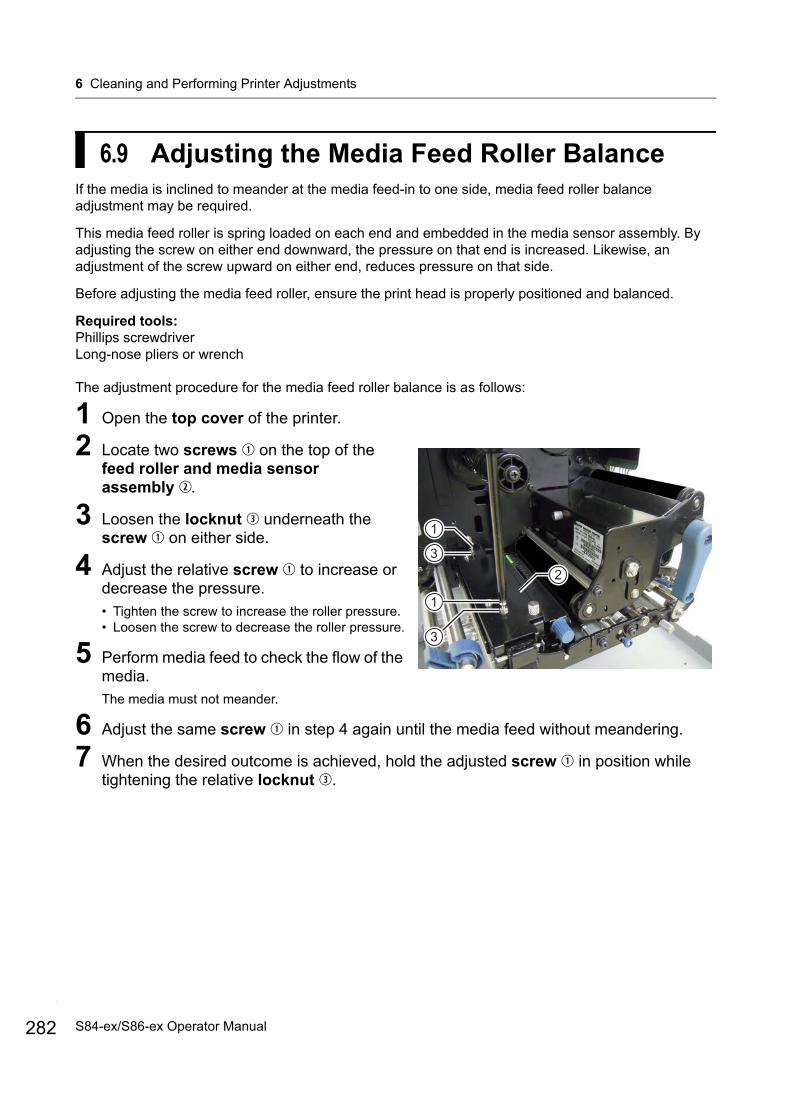
6 Cleaning and Performing Printer Adjustments
282
6.9 Adjusting the Media Feed Roller BalanceIf the media is inclined to meander at the media feed-in to one side, media feed roller balance adjustment may be required.
This media feed roller is spring loaded on each end and embedded in the media sensor assembly. By adjusting the screw on either end downward, the pressure on that end is increased. Likewise, an adjustment of the screw upward on either end, reduces pressure on that side.
Before adjusting the media feed roller, ensure the print head is properly positioned and balanced.
Required tools:Phillips screwdriverLong-nose pliers or wrench
The adjustment procedure for the media feed roller balance is as follows:
1 Open the top cover of the printer.
2 Locate two screws on the top of the feed roller and media sensor assembly .
3 Loosen the locknut underneath the screw on either side.
4 Adjust the relative screw to increase or decrease the pressure.• Tighten the screw to increase the roller pressure.• Loosen the screw to decrease the roller pressure.
5 Perform media feed to check the flow of the media.The media must not meander.
6 Adjust the same screw in step 4 again until the media feed without meandering.
7 When the desired outcome is achieved, hold the adjusted screw in position while tightening the relative locknut .
2
1
1
3
3
S84-ex/S86-ex Operator Manual
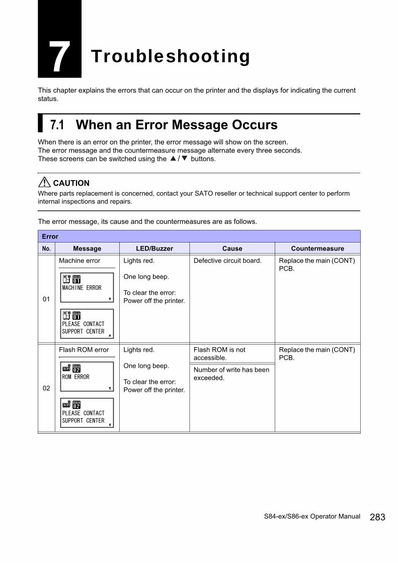
This chapter explains the errors that can occur on the printer and the displays for indicating the current status.
7.1 When an Error Message OccursWhen there is an error on the printer, the error message will show on the screen.The error message and the countermeasure message alternate every three seconds.These screens can be switched using the / buttons.
CAUTIONWhere parts replacement is concerned, contact your SATO reseller or technical support center to perform internal inspections and repairs.
The error message, its cause and the countermeasures are as follows.
7 Troubleshooting
Error
No. Message LED/Buzzer Cause Countermeasure
01
Machine error Lights red.
One long beep.
To clear the error: Power off the printer.
Defective circuit board. Replace the main (CONT) PCB.
02
Flash ROM error Lights red.
One long beep.
To clear the error: Power off the printer.
Flash ROM is not accessible.
Replace the main (CONT) PCB.
Number of write has been exceeded.
283S84-ex/S86-ex Operator Manual
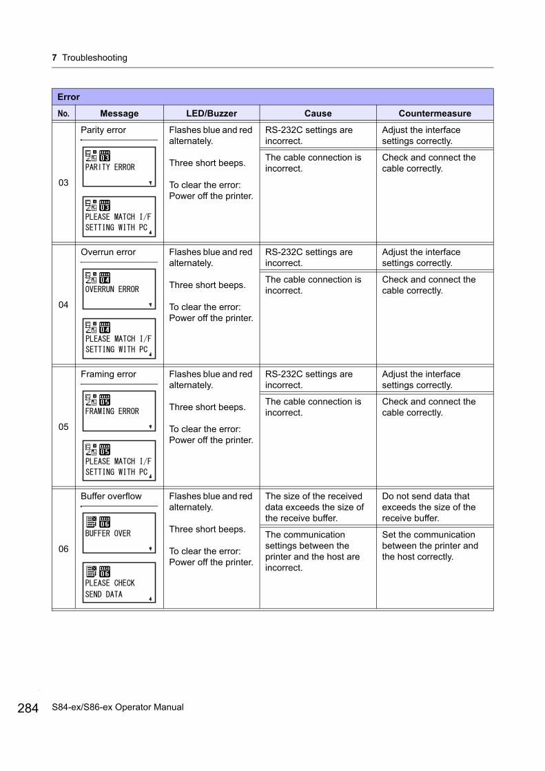
7 Troubleshooting
284
03
Parity error Flashes blue and red alternately.
Three short beeps.
To clear the error: Power off the printer.
RS-232C settings are incorrect.
Adjust the interface settings correctly.
The cable connection is incorrect.
Check and connect the cable correctly.
04
Overrun error Flashes blue and red alternately.
Three short beeps.
To clear the error: Power off the printer.
RS-232C settings are incorrect.
Adjust the interface settings correctly.
The cable connection is incorrect.
Check and connect the cable correctly.
05
Framing error Flashes blue and red alternately.
Three short beeps.
To clear the error: Power off the printer.
RS-232C settings are incorrect.
Adjust the interface settings correctly.
The cable connection is incorrect.
Check and connect the cable correctly.
06
Buffer overflow Flashes blue and red alternately.
Three short beeps.
To clear the error: Power off the printer.
The size of the received data exceeds the size of the receive buffer.
Do not send data that exceeds the size of the receive buffer.
The communication settings between the printer and the host are incorrect.
Set the communication between the printer and the host correctly.
Error
No. Message LED/Buzzer Cause Countermeasure
S84-ex/S86-ex Operator Manual
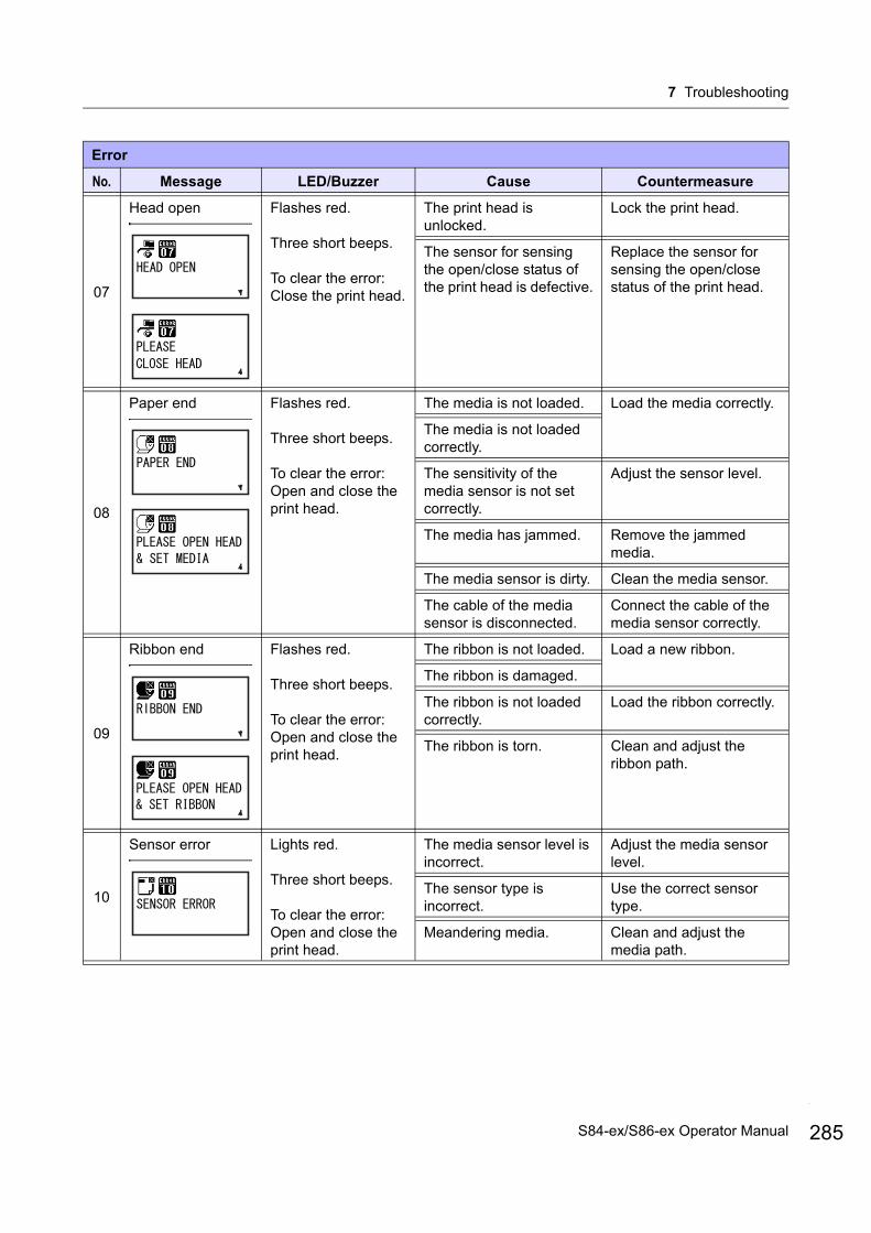
7 Troubleshooting
07
Head open Flashes red.
Three short beeps.
To clear the error:Close the print head.
The print head is unlocked.
Lock the print head.
The sensor for sensing the open/close status of the print head is defective.
Replace the sensor for sensing the open/close status of the print head.
08
Paper end Flashes red.
Three short beeps.
To clear the error:Open and close the print head.
The media is not loaded. Load the media correctly.
The media is not loaded correctly.
The sensitivity of the media sensor is not set correctly.
Adjust the sensor level.
The media has jammed. Remove the jammed media.
The media sensor is dirty. Clean the media sensor.
The cable of the media sensor is disconnected.
Connect the cable of the media sensor correctly.
09
Ribbon end Flashes red.
Three short beeps.
To clear the error:Open and close the print head.
The ribbon is not loaded. Load a new ribbon.
The ribbon is damaged.
The ribbon is not loaded correctly.
Load the ribbon correctly.
The ribbon is torn. Clean and adjust the ribbon path.
10
Sensor error Lights red.
Three short beeps.
To clear the error:Open and close the print head.
The media sensor level is incorrect.
Adjust the media sensor level.
The sensor type is incorrect.
Use the correct sensor type.
Meandering media. Clean and adjust the media path.
Error
No. Message LED/Buzzer Cause Countermeasure
285S84-ex/S86-ex Operator Manual

7 Troubleshooting
286
11
Print head error Lights red.
One long beep.
To clear the error:Power off or change the head check conditions.
The print elements are worn out.
Change print head check conditions to only check for missing elements in barcodes and try to adjust missing elements to white bars.Refer to Section 7.1.2 More Information about Head Check Function for details.
The print head is damaged.
Replace the print head.Refer to Section 8.7.1 Replacing the Print Head for details.
12
Memory write error
Printer memory:
USB memory:
Flashes red.
One long beep.
To clear the error:Power off the printer.
The USB memory is disconnected while writing.
Connect the USB memory.
The copy area in the memory is not sufficient.
Make sure that the memory has sufficient copy area.
Writing to the memory fails.
Replace the memory.
The USB memory is not formatted.
Format the USB memory in the memory mode.Refer to Section 4.2.11 Memory Mode for details.
SD card write error Flashes red.
One long beep.
To clear the error:Power off the printer.
The SD card is not connected.
Connect the SD card.
The SD card is not connected correctly.
Connect the SD card correctly.
The SD card is disconnected while writing.
Connect the SD card.
The SD card read/write fails.
Replace the SD card.
The SD card is not formatted.
Format the SD card in the memory mode.Refer to Section 4.2.11 Memory Mode for details.
The SD card is write-protected.
Release the write-protect of the SD card.
Error
No. Message LED/Buzzer Cause Countermeasure
S84-ex/S86-ex Operator Manual
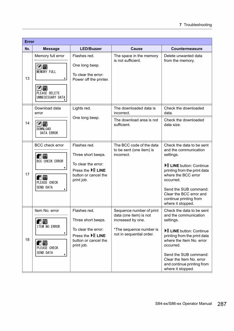
7 Troubleshooting
13
Memory full error Flashes red.
One long beep.
To clear the error:Power off the printer.
The space in the memory is not sufficient.
Delete unwanted data from the memory.
14
Download data error
Lights red.
One long beep.
The downloaded data is incorrect.
Check the downloaded data.
The download area is not sufficient.
Check the downloaded data size.
17
BCC check error Flashes red.
Three short beeps.
To clear the error:
Press the LINE button or cancel the print job.
The BCC code of the data to be sent (one item) is incorrect.
Check the data to be sent and the communication settings.
LINE button: Continue printing from the print data where the BCC error occurred.
Send the SUB command: Clear the BCC error and continue printing from where it stopped.
18
Item No. error Flashes red.
Three short beeps.
To clear the error:
Press the LINE button or cancel the print job.
Sequence number of print data (one item) is not increased by one.
*The sequence number is not in sequential order.
Check the data to be sent and the communication settings.
LINE button: Continue printing from the print data where the Item No. error occurred.
Send the SUB command: Clear the Item No. error and continue printing from where it stopped.
Error
No. Message LED/Buzzer Cause Countermeasure
287S84-ex/S86-ex Operator Manual
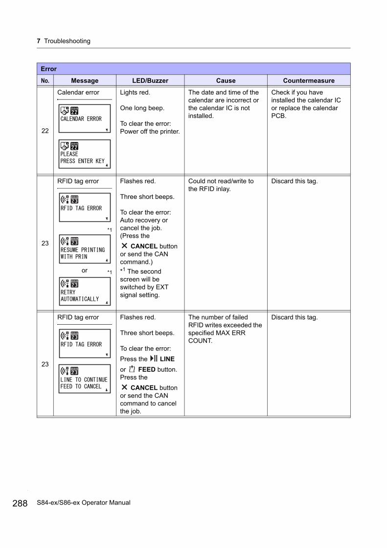
7 Troubleshooting
288
22
Calendar error Lights red.
One long beep.
To clear the error:Power off the printer.
The date and time of the calendar are incorrect or the calendar IC is not installed.
Check if you have installed the calendar IC or replace the calendar PCB.
23
RFID tag error
*1
or *1
Flashes red.
Three short beeps.
To clear the error: Auto recovery or cancel the job. (Press the
CANCEL button or send the CAN command.)
*1 The second screen will be switched by EXT signal setting.
Could not read/write to the RFID inlay.
Discard this tag.
23
RFID tag error Flashes red.
Three short beeps.
To clear the error:
Press the LINE
or FEED button.Press the
CANCEL button or send the CAN command to cancel the job.
The number of failed RFID writes exceeded the specified MAX ERR COUNT.
Discard this tag.
Error
No. Message LED/Buzzer Cause Countermeasure
S84-ex/S86-ex Operator Manual

7 Troubleshooting
26
Overheat error Flashes blue and red alternately.
One long beep.
To clear the error: Stop the operation of the printer and wait until the temperature decreases.
The temperature of the printer has exceeded its tolerance value.
Stop the operation of the printer to let the temperature decrease.
27
Command error Flashes red.
Three short beeps.
To clear the error:
Press the LINE button.
Incorrect command or parameter in the print data.
Caaa: position of error occurrence
<bb>: error command name
cc: error code
Check the print data.Refer to Section 7.1.1 More Information about Command Error for details.
35
CRC check error Flashes red.
Three short beeps.
To clear the error:
Press the LINE button or cancel the print job.
The CRC code of the data to be sent (one item) is incorrect.
Check the data to be sent and the communication settings.
LINE button: Continue printing from the print data where the CRC error occurred.
Send the SUB command: Clear the CRC error and continue printing from where it stopped.
37
Wireless LAN error Flashes blue and red alternately.
Three short beeps.
To clear the error:Power off the printer.
No wireless LAN unit is connected while the printer is in wireless LAN download mode.
Make sure that the wireless LAN unit is connected correctly.
The printer failed to connect to the wireless LAN unit.
Change the wireless LAN unit.*When you change the wireless LAN, the data port and sub port in the communication settings change depending on the settings.
Error
No. Message LED/Buzzer Cause Countermeasure
35
35
37
37
289S84-ex/S86-ex Operator Manual
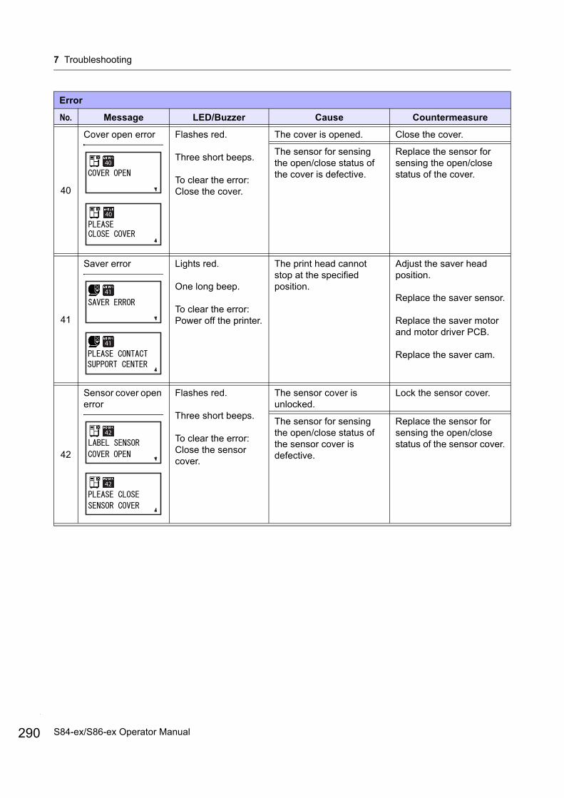
7 Troubleshooting
290
40
Cover open error Flashes red.
Three short beeps.
To clear the error:Close the cover.
The cover is opened. Close the cover.
The sensor for sensing the open/close status of the cover is defective.
Replace the sensor for sensing the open/close status of the cover.
41
Saver error Lights red.
One long beep.
To clear the error:Power off the printer.
The print head cannot stop at the specified position.
Adjust the saver head position.
Replace the saver sensor.
Replace the saver motor and motor driver PCB.
Replace the saver cam.
42
Sensor cover open error
Flashes red.
Three short beeps.
To clear the error:Close the sensor cover.
The sensor cover is unlocked.
Lock the sensor cover.
The sensor for sensing the open/close status of the sensor cover is defective.
Replace the sensor for sensing the open/close status of the sensor cover.
Error
No. Message LED/Buzzer Cause Countermeasure
40
40
41
41
42
42
S84-ex/S86-ex Operator Manual

7 Troubleshooting
7.1.1 More Information about Command Error
Printer motion when detecting a command error When COMMAND ERROR is set to ENABLE in advanced mode, the command error information is shown on the error message (second line), and the print operation is paused.This error can be cleared by pressing the LINE button, but the data in which an error is detected is discarded and cannot be printed.
Location of error occurrence“Caaa” in the command error message shows the location of command error.The number of ESC commands from ESC+A is shown in “aaa”.Note that the ESC+A command is not included in the number of ESC commands, which can be shown up to 999. If the number of ESC commands exceeds 999, it is shown as “999”.
Example)When a command error is detected by the Horizontal Print Position <H> command.
-------: [ESC]AC001: [ESC]V100
C002: [ESC]H99999 => Location of the command error
C003: [ESC]L0202C004: [ESC]M,ABCDEFC005: [ESC]Q1C006: [ESC]Z
In this case, C002 is the location of the error.
Error command nameThe command name, in which an error is detected, is shown in “<bb>”.* A one-byte command name is left aligned.
Error codeThe cause of command error will be indicated in the code in “cc” where an error is being shown.
Code <cc> Cause
01 Analyzed improper command.
02 Received improper parameter.
03 Analyzed improper graphic and external character data.
04 Specified memory area (card slot) is inappropriate.Tried to write to a write-protected media.
05 Number specified by registration command has already been taken.
06 Exceeded the registration area. (Memory full).
07 Data is not registered.
08 The specified print start position is outside the printable area.
09 The printing image is outside the printable area. (Barcode only).
Command error information
291S84-ex/S86-ex Operator Manual

7 Troubleshooting
292
7.1.2 More Information about Head Check Function
The head check function detects the integrity of the heating elements in the print head. However, malfunctions cannot be detected instantaneously — a few printed media may start showing printing defects before the printer warns of a print head error.After detection of a print head error, use a scanner to check all affected media.
When a print head error occurs during normal printing (barcodes, text and graphics)
1 Press and hold down the FEED button for five seconds.HEAD CHECK setting screen shows.
2 Select BARCODE using the / buttons and then press the ENTER button.
3 See if printing can be resumed normally.
If printing resumes, the print head fault does not fall on the barcode area for the current print job. As such, printing may be continued but with degraded print quality and readable barcodes.
If the head check error still occurs and the current print job has to be completed, printing can be forced to resume by holding down the LINE and FEED buttons for five seconds.Read the caution note below before you proceed with this operation.
CAUTIONAlthough restricting the head check type to BARCODE allows you to continue printing, or forcing the printer to resume printing, you should only do so in order to complete an urgent print job. Check the printed media to make sure the output is usable in spite of the head error. As soon as possible, stop using the print head to prevent further damage. If necessary, replace the print head.
Disable the head check function temporarily until the printer is turned off.
HEAD CHECK“NORMAL” : Actual printed area“BARCODE” : Barcode printed area
Head Check OK?
NG
OK
Press the FEED button for five seconds.
ENTER button
Press the LINE + FEED buttons for five seconds.
S84-ex/S86-ex Operator Manual
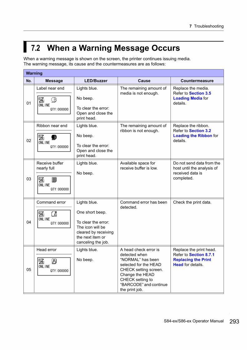
7 Troubleshooting
a
7.2 When a Warning Message OccursWhen a warning message is shown on the screen, the printer continues issuing media.The warning message, its cause and the countermeasures are as follows:
Warning
No. Message LED/Buzzer Cause Countermeasure
01
Label near end Lights blue.
No beep.
To clear the error: Open and close the print head.
The remaining amount of media is not enough.
Replace the media.Refer to Section 3.5 Loading Media for details.
02
Ribbon near end Lights blue.
No beep.
To clear the error: Open and close the print head.
The remaining amount of ribbon is not enough.
Replace the ribbon.Refer to Section 3.2 Loading the Ribbon for details.
03
Receive buffer nearly full
Lights blue.
No beep.
Available space for receive buffer is low.
Do not send data from the host until the analysis of received data is completed.
04
Command error Lights blue.
One short beep.
To clear the error: The icon will be cleared by receiving the next item or canceling the job.
Command error has been detected.
Check the print data.
05
Head error Lights blue.
No beep.
A head check error is detected when “NORMAL” has been selected for the HEAD CHECK setting screen. Change the HEAD CHECK setting to “BARCODE” and continue the print job.
Replace the print head.Refer to Section 8.7.1 Replacing the Print Head for details.
293S84-ex/S86-ex Operator Manual
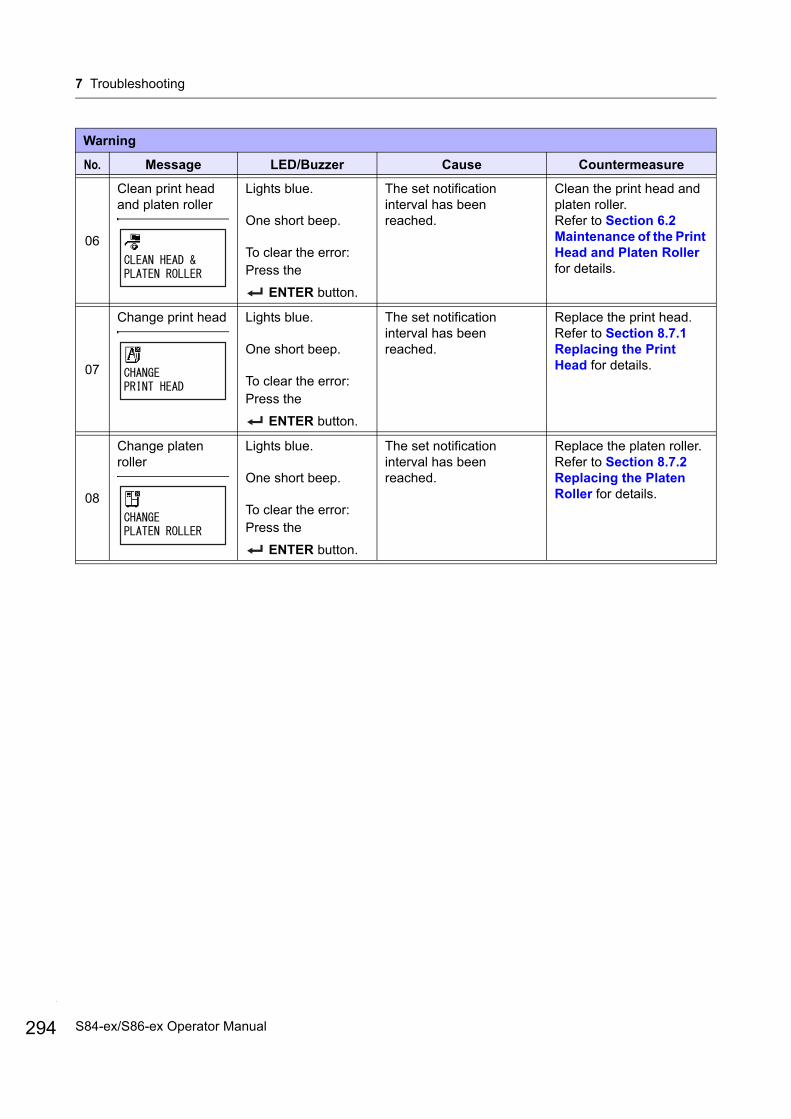
7 Troubleshooting
294
06
Clean print head and platen roller
Lights blue.
One short beep.
To clear the error: Press the
ENTER button.
The set notification interval has been reached.
Clean the print head and platen roller.Refer to Section 6.2 Maintenance of the Print Head and Platen Roller for details.
07
Change print head Lights blue.
One short beep.
To clear the error: Press the
ENTER button.
The set notification interval has been reached.
Replace the print head.Refer to Section 8.7.1 Replacing the Print Head for details.
08
Change platen roller
Lights blue.
One short beep.
To clear the error: Press the
ENTER button.
The set notification interval has been reached.
Replace the platen roller.Refer to Section 8.7.2 Replacing the Platen Roller for details.
Warning
No. Message LED/Buzzer Cause Countermeasure
S84-ex/S86-ex Operator Manual

7 Troubleshooting
7.3 When the LED Lights Red/BlueThe LED will light or flash to show the current status of the printer.The status when the LED lights or flashes is as follows:
LED Printer Status Countermeasure
Light off. The power is off or the printer is in offline mode.
Power on the printer or change it to online mode.
Lights blue. The printer is in online mode. You can operate the printer.
Lights red/Flashes red/
Flashes blue and red alternately.
An error has occurred. Clear the error according to the message.
295S84-ex/S86-ex Operator Manual
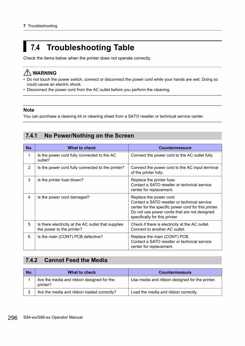
7 Troubleshooting
296
7.4 Troubleshooting TableCheck the items below when the printer does not operate correctly.
WARNING• Do not touch the power switch, connect or disconnect the power cord while your hands are wet. Doing so
could cause an electric shock.• Disconnect the power cord from the AC outlet before you perform the cleaning.
NoteYou can purchase a cleaning kit or cleaning sheet from a SATO reseller or technical service center.
7.4.1 No Power/Nothing on the Screen
7.4.2 Cannot Feed the Media
No. What to check Countermeasure
1 Is the power cord fully connected to the AC outlet?
Connect the power cord to the AC outlet fully.
2 Is the power cord fully connected to the printer? Connect the power cord to the AC input terminal of the printer fully.
3 Is the printer fuse blown? Replace the printer fuse.Contact a SATO reseller or technical service center for replacement.
4 Is the power cord damaged? Replace the power cord.Contact a SATO reseller or technical service center for the specific power cord for this printer. Do not use power cords that are not designed specifically for this printer.
5 Is there electricity at the AC outlet that supplies the power to the printer?
Check if there is electricity at the AC outlet.Connect to another AC outlet.
6 Is the main (CONT) PCB defective? Replace the main (CONT) PCB.Contact a SATO reseller or technical service center for replacement.
No. What to check Countermeasure
1 Are the media and ribbon designed for the printer?
Use media and ribbon designed for the printer.
2 Are the media and ribbon loaded correctly? Load the media and ribbon correctly.
S84-ex/S86-ex Operator Manual
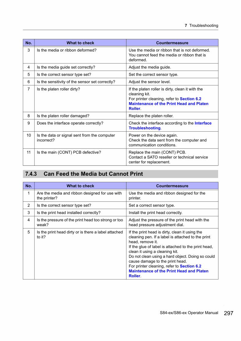
7 Troubleshooting
7.4.3 Can Feed the Media but Cannot Print
3 Is the media or ribbon deformed? Use the media or ribbon that is not deformed. You cannot feed the media or ribbon that is deformed.
4 Is the media guide set correctly? Adjust the media guide.
5 Is the correct sensor type set? Set the correct sensor type.
6 Is the sensitivity of the sensor set correctly? Adjust the sensor level.
7 Is the platen roller dirty? If the platen roller is dirty, clean it with the cleaning kit.For printer cleaning, refer to Section 6.2 Maintenance of the Print Head and Platen Roller.
8 Is the platen roller damaged? Replace the platen roller.
9 Does the interface operate correctly? Check the interface according to the Interface Troubleshooting.
10 Is the data or signal sent from the computer incorrect?
Power on the device again.Check the data sent from the computer and communication conditions.
11 Is the main (CONT) PCB defective? Replace the main (CONT) PCB.Contact a SATO reseller or technical service center for replacement.
No. What to check Countermeasure
1 Are the media and ribbon designed for use with the printer?
Use the media and ribbon designed for the printer.
2 Is the correct sensor type set? Set a correct sensor type.
3 Is the print head installed correctly? Install the print head correctly.
4 Is the pressure of the print head too strong or too weak?
Adjust the pressure of the print head with the head pressure adjustment dial.
5 Is the print head dirty or is there a label attached to it?
If the print head is dirty, clean it using the cleaning pen. If a label is attached to the print head, remove it.If the glue of label is attached to the print head, clean it using a cleaning kit.Do not clean using a hard object. Doing so could cause damage to the print head.For printer cleaning, refer to Section 6.2 Maintenance of the Print Head and Platen Roller.
No. What to check Countermeasure
297S84-ex/S86-ex Operator Manual
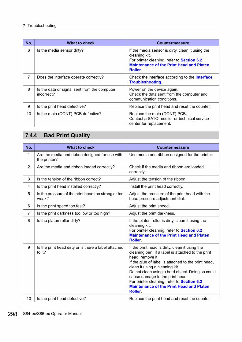
7 Troubleshooting
298
7.4.4 Bad Print Quality
6 Is the media sensor dirty? If the media sensor is dirty, clean it using the cleaning kit.For printer cleaning, refer to Section 6.2 Maintenance of the Print Head and Platen Roller.
7 Does the interface operate correctly? Check the interface according to the Interface Troubleshooting.
8 Is the data or signal sent from the computer incorrect?
Power on the device again.Check the data sent from the computer and communication conditions.
9 Is the print head defective? Replace the print head and reset the counter.
10 Is the main (CONT) PCB defective? Replace the main (CONT) PCB.Contact a SATO reseller or technical service center for replacement.
No. What to check Countermeasure
1 Are the media and ribbon designed for use with the printer?
Use media and ribbon designed for the printer.
2 Are the media and ribbon loaded correctly? Check if the media and ribbon are loaded correctly.
3 Is the tension of the ribbon correct? Adjust the tension of the ribbon.
4 Is the print head installed correctly? Install the print head correctly.
5 Is the pressure of the print head too strong or too weak?
Adjust the pressure of the print head with the head pressure adjustment dial.
6 Is the print speed too fast? Adjust the print speed.
7 Is the print darkness too low or too high? Adjust the print darkness.
8 Is the platen roller dirty? If the platen roller is dirty, clean it using the cleaning kit.For printer cleaning, refer to Section 6.2 Maintenance of the Print Head and Platen Roller.
9 Is the print head dirty or is there a label attached to it?
If the print head is dirty, clean it using the cleaning pen. If a label is attached to the print head, remove it.If the glue of label is attached to the print head, clean it using a cleaning kit.Do not clean using a hard object. Doing so could cause damage to the print head.For printer cleaning, refer to Section 6.2 Maintenance of the Print Head and Platen Roller.
10 Is the print head defective? Replace the print head and reset the counter.
No. What to check Countermeasure
S84-ex/S86-ex Operator Manual
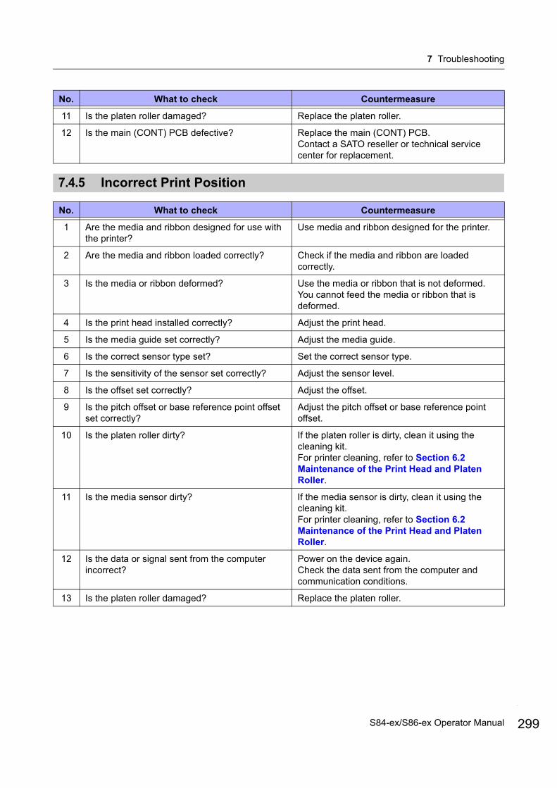
7 Troubleshooting
7.4.5 Incorrect Print Position
11 Is the platen roller damaged? Replace the platen roller.
12 Is the main (CONT) PCB defective? Replace the main (CONT) PCB.Contact a SATO reseller or technical service center for replacement.
No. What to check Countermeasure
1 Are the media and ribbon designed for use with the printer?
Use media and ribbon designed for the printer.
2 Are the media and ribbon loaded correctly? Check if the media and ribbon are loaded correctly.
3 Is the media or ribbon deformed? Use the media or ribbon that is not deformed. You cannot feed the media or ribbon that is deformed.
4 Is the print head installed correctly? Adjust the print head.
5 Is the media guide set correctly? Adjust the media guide.
6 Is the correct sensor type set? Set the correct sensor type.
7 Is the sensitivity of the sensor set correctly? Adjust the sensor level.
8 Is the offset set correctly? Adjust the offset.
9 Is the pitch offset or base reference point offset set correctly?
Adjust the pitch offset or base reference point offset.
10 Is the platen roller dirty? If the platen roller is dirty, clean it using the cleaning kit.For printer cleaning, refer to Section 6.2 Maintenance of the Print Head and Platen Roller.
11 Is the media sensor dirty? If the media sensor is dirty, clean it using the cleaning kit.For printer cleaning, refer to Section 6.2 Maintenance of the Print Head and Platen Roller.
12 Is the data or signal sent from the computer incorrect?
Power on the device again.Check the data sent from the computer and communication conditions.
13 Is the platen roller damaged? Replace the platen roller.
No. What to check Countermeasure
299S84-ex/S86-ex Operator Manual
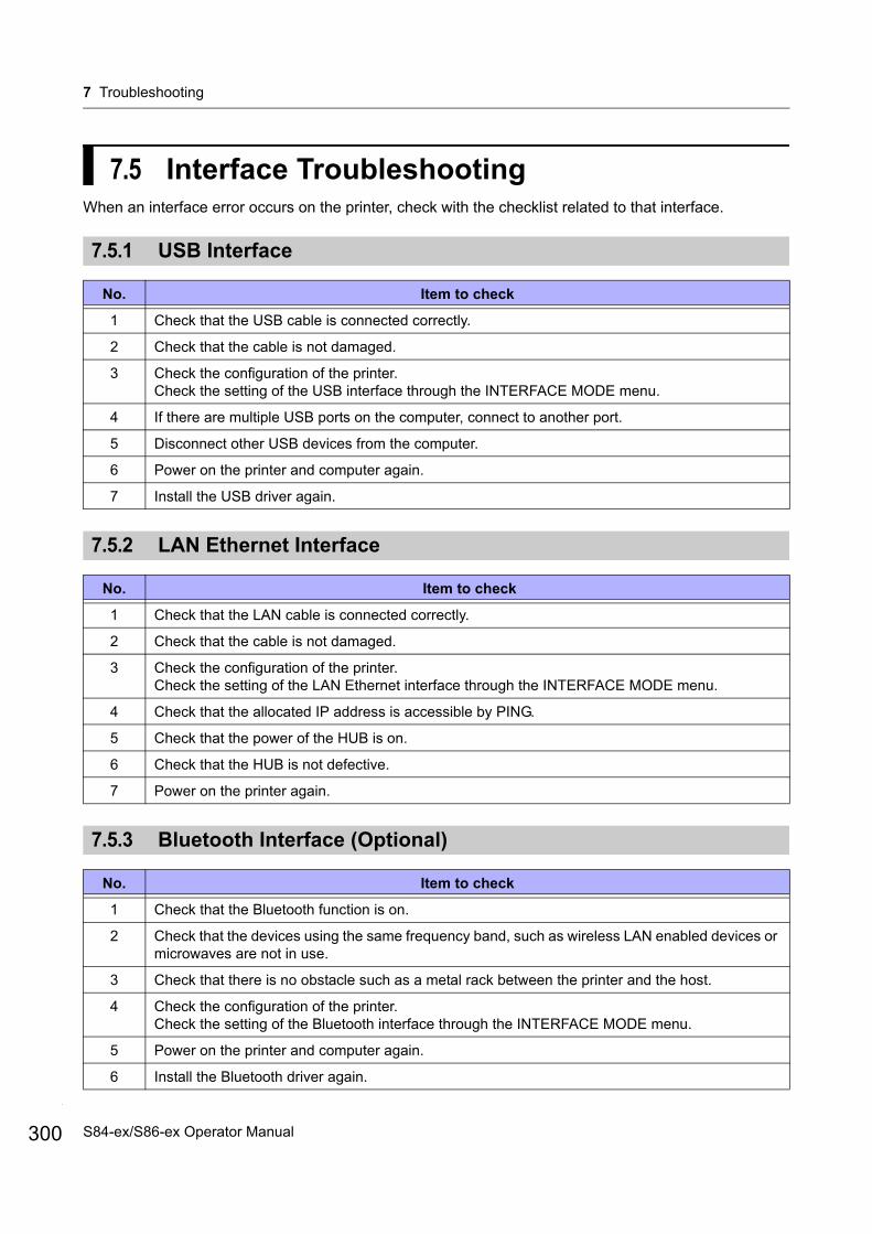
7 Troubleshooting
300
7.5 Interface TroubleshootingWhen an interface error occurs on the printer, check with the checklist related to that interface.
7.5.1 USB Interface
7.5.2 LAN Ethernet Interface
7.5.3 Bluetooth Interface (Optional)
No. Item to check
1 Check that the USB cable is connected correctly.
2 Check that the cable is not damaged.
3 Check the configuration of the printer.Check the setting of the USB interface through the INTERFACE MODE menu.
4 If there are multiple USB ports on the computer, connect to another port.
5 Disconnect other USB devices from the computer.
6 Power on the printer and computer again.
7 Install the USB driver again.
No. Item to check
1 Check that the LAN cable is connected correctly.
2 Check that the cable is not damaged.
3 Check the configuration of the printer.Check the setting of the LAN Ethernet interface through the INTERFACE MODE menu.
4 Check that the allocated IP address is accessible by PING.
5 Check that the power of the HUB is on.
6 Check that the HUB is not defective.
7 Power on the printer again.
No. Item to check
1 Check that the Bluetooth function is on.
2 Check that the devices using the same frequency band, such as wireless LAN enabled devices or microwaves are not in use.
3 Check that there is no obstacle such as a metal rack between the printer and the host.
4 Check the configuration of the printer.Check the setting of the Bluetooth interface through the INTERFACE MODE menu.
5 Power on the printer and computer again.
6 Install the Bluetooth driver again.
S84-ex/S86-ex Operator Manual
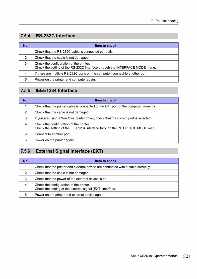
7 Troubleshooting
7.5.4 RS-232C Interface
7.5.5 IEEE1284 Interface
7.5.6 External Signal Interface (EXT)
No. Item to check
1 Check that the RS-232C cable is connected correctly.
2 Check that the cable is not damaged.
3 Check the configuration of the printer.Check the setting of the RS-232C interface through the INTERFACE MODE menu.
4 If there are multiple RS-232C ports on the computer, connect to another port.
5 Power on the printer and computer again.
No. Item to check
1 Check that the printer cable is connected to the LPT port of the computer correctly.
2 Check that the cable is not damaged.
3 If you are using a Windows printer driver, check that the correct port is selected.
4 Check the configuration of the printer.Check the setting of the IEEE1284 interface through the INTERFACE MODE menu.
5 Connect to another port.
6 Power on the printer again.
No. Item to check
1 Check that the printer and external device are connected with a cable correctly.
2 Check that the cable is not damaged.
3 Check that the power of the external device is on.
4 Check the configuration of the printer.Check the setting of the external signal (EXT) interface.
5 Power on the printer and external device again.
301S84-ex/S86-ex Operator Manual
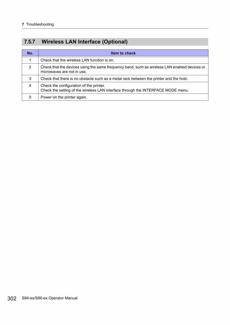
7 Troubleshooting
302
7.5.7 Wireless LAN Interface (Optional)
No. Item to check
1 Check that the wireless LAN function is on.
2 Check that the devices using the same frequency band, such as wireless LAN enabled devices or microwaves are not in use.
3 Check that there is no obstacle such as a metal rack between the printer and the host.
4 Check the configuration of the printer.Check the setting of the wireless LAN interface through the INTERFACE MODE menu.
5 Power on the printer again.
S84-ex/S86-ex Operator Manual
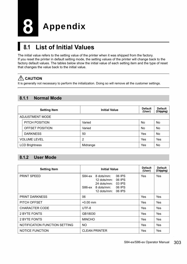
8.1 List of Initial ValuesThe initial value refers to the setting value of the printer when it was shipped from the factory.If you reset the printer in default setting mode, the setting values of the printer will change back to the factory default values. The tables below show the initial value of each setting item and the type of reset that changes the value back to the initial value.
CAUTIONIt is generally not necessary to perform the initialization. Doing so will remove all the customer settings.
8.1.1 Normal Mode
8.1.2 User Mode
8 Appendix
Setting Item Initial Value Default(User)
Default(Shipping)
ADJUSTMENT MODE
PITCH POSITION Varied No No
OFFSET POSITION Varied No No
DARKNESS 50 Yes No
VOLUME LEVEL 2 Yes Yes
LCD Brightness Midrange Yes No
Setting Item Initial Value Default(User)
Default(Shipping)
PRINT SPEED S84-ex 8 dots/mm: 06 IPS12 dots/mm: 06 IPS24 dots/mm: 03 IPS
S86-ex 8 dots/mm: 06 IPS12 dots/mm: 06 IPS
Yes Yes
PRINT DARKNESS 06 Yes Yes
PITCH OFFSET +0.00 mm Yes Yes
CHARACTER CODE UTF-8 Yes Yes
2 BYTE FONTS GB18030 Yes Yes
2 BYTE FONTS MINCHO Yes Yes
NOTIFICATION FUNCTION SETTING NO Yes Yes
NOTICE FUNCTION CLEAN PRINTER Yes Yes
303S84-ex/S86-ex Operator Manual

8 Appendix
304
8.1.3 Interface Mode
NOTICE FUNCTION DISABLE Yes Yes
CLEAN PRINTER NOTICE DISTANCE 0 m Yes Yes
CHANGE ROLLER NOTICE DISTANCE 0 km Yes Yes
CHANGE HEAD NOTICE DISTANCE 0 km Yes Yes
Setting Item Initial Value Default(User)
Default(Shipping)
INTERFACE AUTO SELECT DISABLE Yes Yes
INTERFACE SETTING NO - -
PORT SELECT DATA PORT Yes Yes
DATA PORT USB Yes Yes
SUB PORT NONE Yes Yes
LAN
DHCP SETTING DISABLE Yes No
IPv4 ADDRESS 192.168.001.001 Yes No
IPv4 SUBNET MASK 255.255.255.000 Yes No
IPv4 GATEWAY ADR 0.0.0.0 Yes No
IPv6 RESOLUTION AUTO Yes No
IPv6 ADDRESS 0000:0000:0000:0000:0000:0000:0000:0000
Yes No
PREFIX LENGTH 64 Yes No
DEFAULT ROUTER 0000:0000:0000:0000:0000:0000:0000:0000
Yes No
PORT NUMBER1 1024 Yes No
PORT NUMBER2 1025 Yes No
PORT NUMBER3 9100 Yes No
PROTOCOL STATUS5 Yes Yes
ITEM NO. CHECK DISABLE (When STATUS5 is selected) Yes Yes
BCC CHECK DISABLE (When STATUS5 is selected) Yes Yes
STATUS REPLY TIMING ENQ (When STATUS4 is selected) Yes Yes
Setting Item Initial Value Default(User)
Default(Shipping)
S84-ex/S86-ex Operator Manual
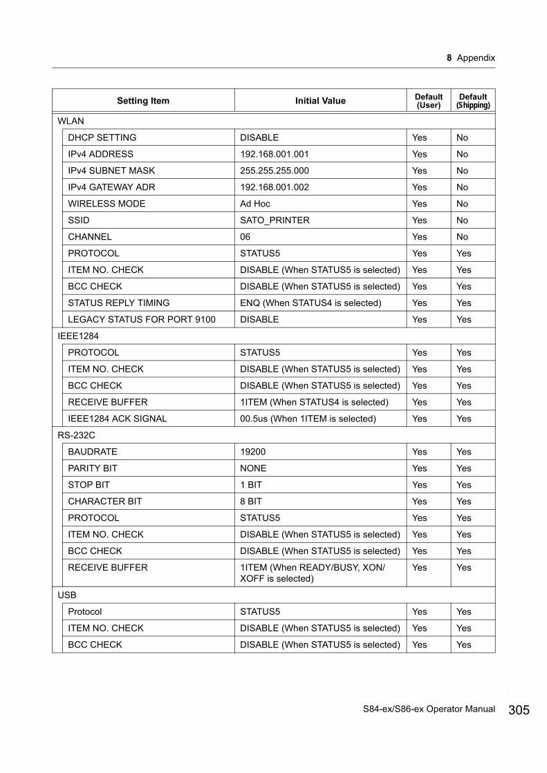
8 Appendix
WLAN
DHCP SETTING DISABLE Yes No
IPv4 ADDRESS 192.168.001.001 Yes No
IPv4 SUBNET MASK 255.255.255.000 Yes No
IPv4 GATEWAY ADR 192.168.001.002 Yes No
WIRELESS MODE Ad Hoc Yes No
SSID SATO_PRINTER Yes No
CHANNEL 06 Yes No
PROTOCOL STATUS5 Yes Yes
ITEM NO. CHECK DISABLE (When STATUS5 is selected) Yes Yes
BCC CHECK DISABLE (When STATUS5 is selected) Yes Yes
STATUS REPLY TIMING ENQ (When STATUS4 is selected) Yes Yes
LEGACY STATUS FOR PORT 9100 DISABLE Yes Yes
IEEE1284
PROTOCOL STATUS5 Yes Yes
ITEM NO. CHECK DISABLE (When STATUS5 is selected) Yes Yes
BCC CHECK DISABLE (When STATUS5 is selected) Yes Yes
RECEIVE BUFFER 1ITEM (When STATUS4 is selected) Yes Yes
IEEE1284 ACK SIGNAL 00.5us (When 1ITEM is selected) Yes Yes
RS-232C
BAUDRATE 19200 Yes Yes
PARITY BIT NONE Yes Yes
STOP BIT 1 BIT Yes Yes
CHARACTER BIT 8 BIT Yes Yes
PROTOCOL STATUS5 Yes Yes
ITEM NO. CHECK DISABLE (When STATUS5 is selected) Yes Yes
BCC CHECK DISABLE (When STATUS5 is selected) Yes Yes
RECEIVE BUFFER 1ITEM (When READY/BUSY, XON/XOFF is selected)
Yes Yes
USB
Protocol STATUS5 Yes Yes
ITEM NO. CHECK DISABLE (When STATUS5 is selected) Yes Yes
BCC CHECK DISABLE (When STATUS5 is selected) Yes Yes
Setting Item Initial Value Default(User)
Default(Shipping)
305S84-ex/S86-ex Operator Manual

8 Appendix
306
Bluetooth
Authentication Level NONE Yes Yes
PIN CODE 0000000000000000 Yes Yes
DEVICE NAME SATO_PRINTER Yes Yes
DISCOVERY SETTING ENABLE Yes Yes
PARAMETER SETTING(ISI) 0800 Yes Yes
PARAMETER SETTING(ISW) 0012 Yes Yes
PARAMETER SETTING(PSI) 0800 Yes Yes
PARAMETER SETTING(PSW) 0012 Yes Yes
PROTOCOL STATUS4 Yes Yes
CRC CHECK DISABLE Yes Yes
IGNORE CR/LF NO Yes Yes
IGNORE CAN/DLE NO (When STATUS4, MULTI is selected in IEEE1284)
Yes Yes
SNTP FUNCTION DISABLE Yes No
IPv4/6 select IPv4 Yes No
NTP IPv4 ADDRESSNTP IPv6 ADDRESS
IPv4: 000.000.000.000IPv6: 0000:0000:0000:0000:
0000:0000:0000:0000
Yes No
TIME ZONE 00:00 Yes No
ERROR NOTICE DISABLE Yes No
SNMP FUNCTION DISABLE Yes No
SNMP SETTING
COMMUNITY NAME SNMP v1/v2c[1] : publicSNMP v1/v2c[2] : NULL
No No
COMMUNITY WRITE DISABLE No No
USER NAME Null No No
AUTH PROTOCOL NONE No No
AUTH KEY Null No No
PRIVACY PROTOCOL NONE No No
PRIVACY KEY Null No No
USER MIB WRITE DISABLE No No
TRAP SET
TRAP TYPE SELECT SNMPv2c No No
TRAP DISABLE No No
COMMUNITY NAME Null No No
Setting Item Initial Value Default(User)
Default(Shipping)
S84-ex/S86-ex Operator Manual

8 Appendix
8.1.4 Memory Mode
8.1.5 Advanced Mode
TRAP SET
USER NAME Null No No
AUTH PROTOCOL NONE No No
AUTH KEY Null No No
PRIVACY PROTOCOL NONE No No
PRIVACY KEY Null No No
IPv4/6 select IPv4 No No
TRAP IPv4 ADR 000.000.000.000 No No
TRAP IPv6 ADR 0000:0000:0000:0000:0000:0000:0000:0000
No No
Setting Item Initial Value Default(User)
Default(Shipping)
SLOT SETTING NO Yes Yes
CARD SLOT SELECT SLOT0 RAM Yes Yes
CARD SLOT SELECT SLOT1 FROM Yes Yes
CARD SLOT SELECT SLOT2 SD Yes Yes
MEMORY MODE MEMORY SIZE - -
STORED CONTENTS FORM OVERLAY - -
MEMORY FORMAT NO - -
FORMAT START NO - -
Setting Item Initial Value Default(User)
Default(Shipping)
PRINTER TYPE DISPENSER Yes Yes
BACKFEED MOTION BEFORE Yes Yes
PRINT METHOD TRANSFER (Set to DIRECT with direct thermal model)
Yes Yes
PITCH SENSOR ENABLE (When CONTINUOUS is selected)
Yes Yes
SENSOR TYPE GAP Yes Yes
COMMAND ERROR DISABLE Yes Yes
Setting Item Initial Value Default(User)
Default(Shipping)
307S84-ex/S86-ex Operator Manual
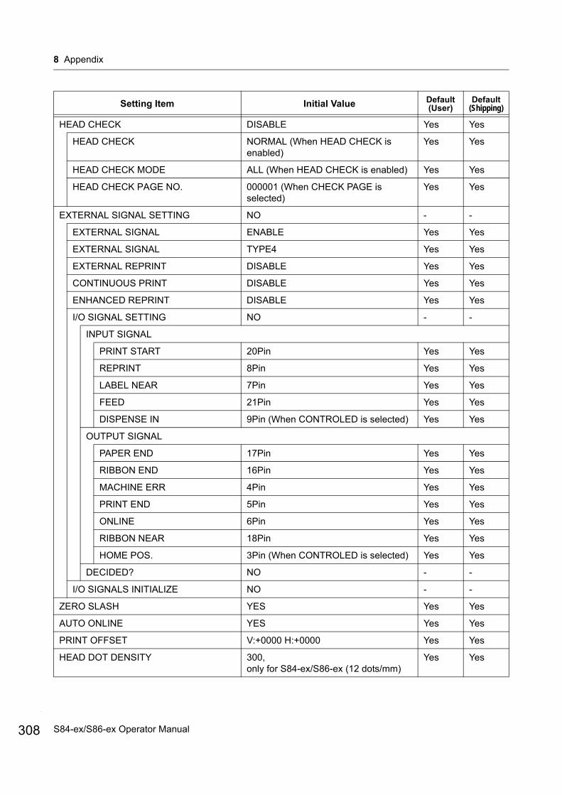
8 Appendix
308
HEAD CHECK DISABLE Yes Yes
HEAD CHECK NORMAL (When HEAD CHECK is enabled)
Yes Yes
HEAD CHECK MODE ALL (When HEAD CHECK is enabled) Yes Yes
HEAD CHECK PAGE NO. 000001 (When CHECK PAGE is selected)
Yes Yes
EXTERNAL SIGNAL SETTING NO - -
EXTERNAL SIGNAL ENABLE Yes Yes
EXTERNAL SIGNAL TYPE4 Yes Yes
EXTERNAL REPRINT DISABLE Yes Yes
CONTINUOUS PRINT DISABLE Yes Yes
ENHANCED REPRINT DISABLE Yes Yes
I/O SIGNAL SETTING NO - -
INPUT SIGNAL
PRINT START 20Pin Yes Yes
REPRINT 8Pin Yes Yes
LABEL NEAR 7Pin Yes Yes
FEED 21Pin Yes Yes
DISPENSE IN 9Pin (When CONTROLED is selected) Yes Yes
OUTPUT SIGNAL
PAPER END 17Pin Yes Yes
RIBBON END 16Pin Yes Yes
MACHINE ERR 4Pin Yes Yes
PRINT END 5Pin Yes Yes
ONLINE 6Pin Yes Yes
RIBBON NEAR 18Pin Yes Yes
HOME POS. 3Pin (When CONTROLED is selected) Yes Yes
DECIDED? NO - -
I/O SIGNALS INITIALIZE NO - -
ZERO SLASH YES Yes Yes
AUTO ONLINE YES Yes Yes
PRINT OFFSET V:+0000 H:+0000 Yes Yes
HEAD DOT DENSITY 300,only for S84-ex/S86-ex (12 dots/mm)
Yes Yes
Setting Item Initial Value Default(User)
Default(Shipping)
S84-ex/S86-ex Operator Manual
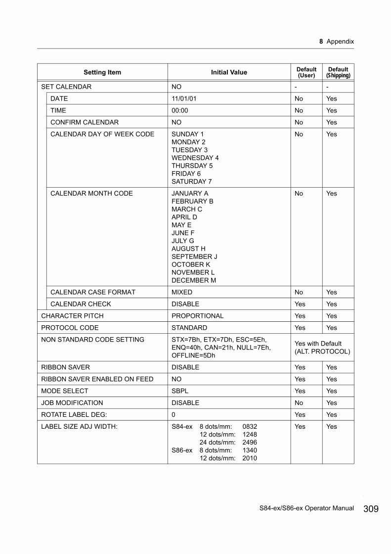
8 Appendix
SET CALENDAR NO - -
DATE 11/01/01 No Yes
TIME 00:00 No Yes
CONFIRM CALENDAR NO No Yes
CALENDAR DAY OF WEEK CODE SUNDAY 1MONDAY 2TUESDAY 3WEDNESDAY 4THURSDAY 5FRIDAY 6SATURDAY 7
No Yes
CALENDAR MONTH CODE JANUARY AFEBRUARY BMARCH CAPRIL DMAY EJUNE FJULY GAUGUST HSEPTEMBER JOCTOBER KNOVEMBER LDECEMBER M
No Yes
CALENDAR CASE FORMAT MIXED No Yes
CALENDAR CHECK DISABLE Yes Yes
CHARACTER PITCH PROPORTIONAL Yes Yes
PROTOCOL CODE STANDARD Yes Yes
NON STANDARD CODE SETTING STX=7Bh, ETX=7Dh, ESC=5Eh, ENQ=40h, CAN=21h, NULL=7Eh, OFFLINE=5Dh
Yes with Default(ALT. PROTOCOL)
RIBBON SAVER DISABLE Yes Yes
RIBBON SAVER ENABLED ON FEED NO Yes Yes
MODE SELECT SBPL Yes Yes
JOB MODIFICATION DISABLE No Yes
ROTATE LABEL DEG: 0 Yes Yes
LABEL SIZE ADJ WIDTH: S84-ex 8 dots/mm: 083212 dots/mm: 124824 dots/mm: 2496
S86-ex 8 dots/mm: 134012 dots/mm: 2010
Yes Yes
Setting Item Initial Value Default(User)
Default(Shipping)
309S84-ex/S86-ex Operator Manual

8 Appendix
310
8.1.6 Hex Dump Mode
8.1.7 RFID User Mode
LABEL SIZE ADJ HEIGHT: S84-ex 8 dots/mm: 2000012 dots/mm: 1800024 dots/mm: 9600
S86-ex 8 dots/mm: 999212 dots/mm: 14988
No No
IGNORE A1 NO Yes Yes
LCD POWER SAVING 00 MIN Yes Yes
LED INDICATION ON Yes Yes
ERROR INDICATION NONE Yes Yes
Setting Item Initial Value Default(User)
Default(Shipping)
SELECT DUMP DATA RECEIVE DATA - -
HEX DUMP NORMAL - -
Setting Item Initial Value Default(User)
Default(Shipping)
RFID LIFE COUNT SUCCESS 000000 - -
RFID LIFE COUNT FAILURE 000000 - -
RFID LIFE COUNT TOTAL 000000 - -
RFID COUNT SUCCESS 000000 No Yes
RFID COUNT FAILURE 000000 No Yes
RFID COUNT TOTAL 000000 No Yes
CLEAR RFID COUNT NO - -
RFID LABEL DATA RETRY No Yes
MAX ERR COUNT 1 TIME(S) No Yes
RFID ERR SLASH YES No Yes
RFID ERR OUTPUT LEVEL No Yes
LENGTH OF PULSE 100 msec No Yes
VIEW EPC DATA/VIEW TID DATA/VIEW USER DATA/VIEW PC DATA
NO - -
ANTENNA PITCH STANDARD No No
Setting Item Initial Value Default(User)
Default(Shipping)
S84-ex/S86-ex Operator Manual
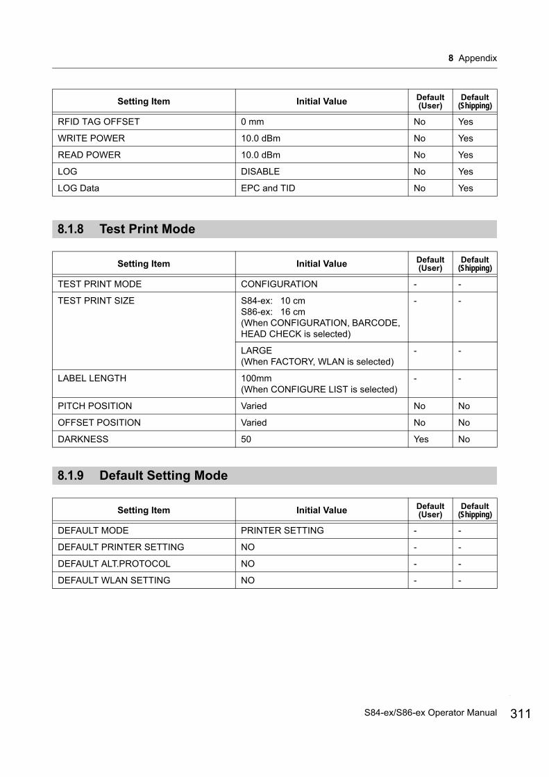
8 Appendix
8.1.8 Test Print Mode
8.1.9 Default Setting Mode
RFID TAG OFFSET 0 mm No Yes
WRITE POWER 10.0 dBm No Yes
READ POWER 10.0 dBm No Yes
LOG DISABLE No Yes
LOG Data EPC and TID No Yes
Setting Item Initial Value Default(User)
Default(Shipping)
TEST PRINT MODE CONFIGURATION - -
TEST PRINT SIZE S84-ex: 10 cmS86-ex: 16 cm(When CONFIGURATION, BARCODE, HEAD CHECK is selected)
- -
LARGE(When FACTORY, WLAN is selected)
- -
LABEL LENGTH 100mm(When CONFIGURE LIST is selected)
- -
PITCH POSITION Varied No No
OFFSET POSITION Varied No No
DARKNESS 50 Yes No
Setting Item Initial Value Default(User)
Default(Shipping)
DEFAULT MODE PRINTER SETTING - -
DEFAULT PRINTER SETTING NO - -
DEFAULT ALT.PROTOCOL NO - -
DEFAULT WLAN SETTING NO - -
Setting Item Initial Value Default(User)
Default(Shipping)
311S84-ex/S86-ex Operator Manual
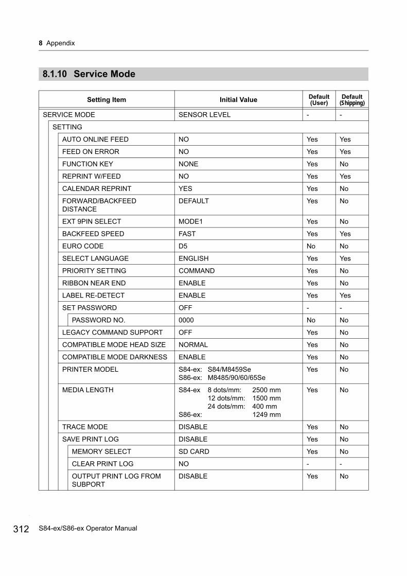
8 Appendix
312
8.1.10 Service Mode
Setting Item Initial Value Default(User)
Default(Shipping)
SERVICE MODE SENSOR LEVEL - -
SETTING
AUTO ONLINE FEED NO Yes Yes
FEED ON ERROR NO Yes Yes
FUNCTION KEY NONE Yes No
REPRINT W/FEED NO Yes Yes
CALENDAR REPRINT YES Yes No
FORWARD/BACKFEED DISTANCE
DEFAULT Yes No
EXT 9PIN SELECT MODE1 Yes No
BACKFEED SPEED FAST Yes Yes
EURO CODE D5 No No
SELECT LANGUAGE ENGLISH Yes Yes
PRIORITY SETTING COMMAND Yes No
RIBBON NEAR END ENABLE Yes No
LABEL RE-DETECT ENABLE Yes Yes
SET PASSWORD OFF - -
PASSWORD NO. 0000 No No
LEGACY COMMAND SUPPORT OFF Yes No
COMPATIBLE MODE HEAD SIZE NORMAL Yes No
COMPATIBLE MODE DARKNESS ENABLE Yes No
PRINTER MODEL S84-ex: S84/M8459SeS86-ex: M8485/90/60/65Se
Yes No
MEDIA LENGTH S84-ex 8 dots/mm: 2500 mm12 dots/mm: 1500 mm24 dots/mm: 400 mm
S86-ex: 1249 mm
Yes No
TRACE MODE DISABLE Yes No
SAVE PRINT LOG DISABLE Yes No
MEMORY SELECT SD CARD Yes No
CLEAR PRINT LOG NO - -
OUTPUT PRINT LOG FROM SUBPORT
DISABLE Yes No
S84-ex/S86-ex Operator Manual
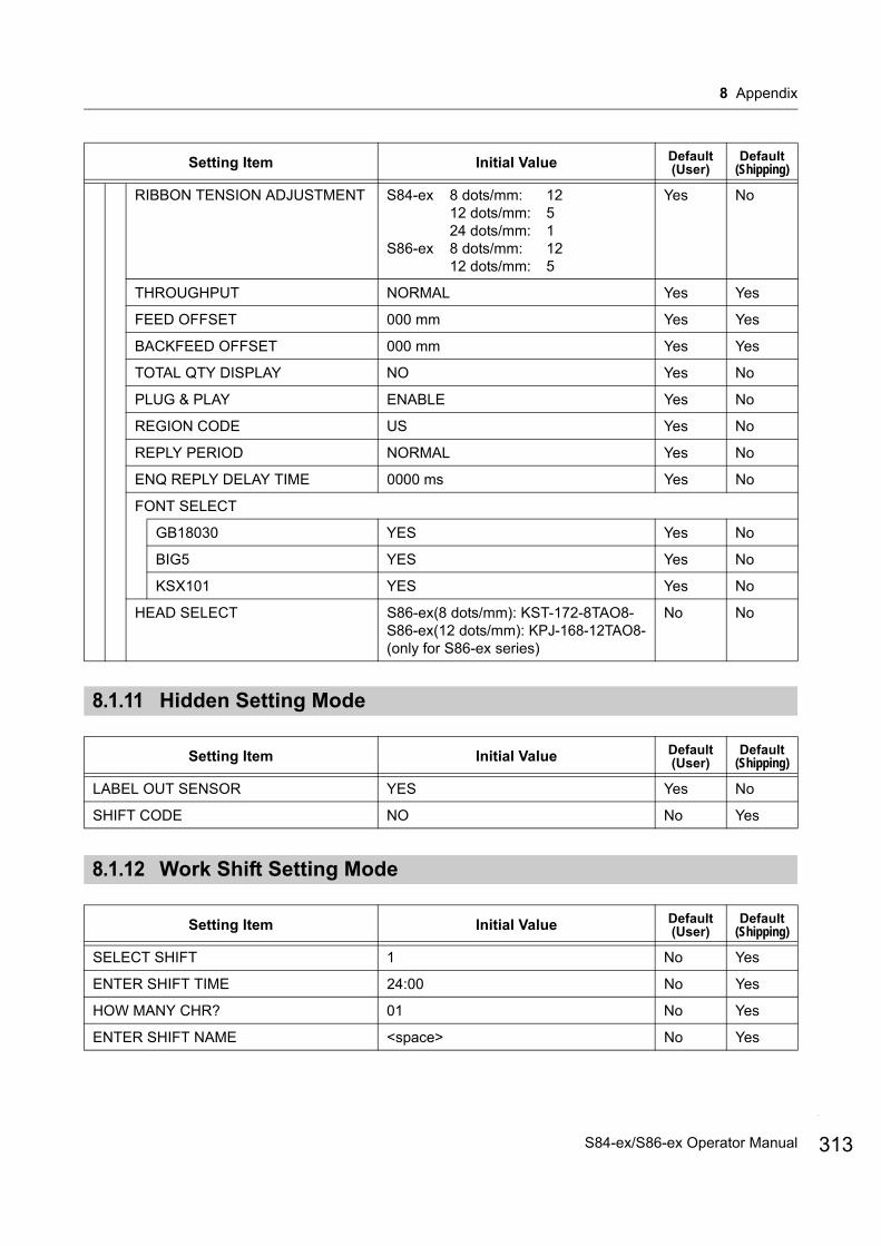
8 Appendix
8.1.11 Hidden Setting Mode
8.1.12 Work Shift Setting Mode
RIBBON TENSION ADJUSTMENT S84-ex 8 dots/mm: 1212 dots/mm: 524 dots/mm: 1
S86-ex 8 dots/mm: 1212 dots/mm: 5
Yes No
THROUGHPUT NORMAL Yes Yes
FEED OFFSET 000 mm Yes Yes
BACKFEED OFFSET 000 mm Yes Yes
TOTAL QTY DISPLAY NO Yes No
PLUG & PLAY ENABLE Yes No
REGION CODE US Yes No
REPLY PERIOD NORMAL Yes No
ENQ REPLY DELAY TIME 0000 ms Yes No
FONT SELECT
GB18030 YES Yes No
BIG5 YES Yes No
KSX101 YES Yes No
HEAD SELECT S86-ex(8 dots/mm): KST-172-8TAO8-S86-ex(12 dots/mm): KPJ-168-12TAO8-(only for S86-ex series)
No No
Setting Item Initial Value Default(User)
Default(Shipping)
LABEL OUT SENSOR YES Yes No
SHIFT CODE NO No Yes
Setting Item Initial Value Default(User)
Default(Shipping)
SELECT SHIFT 1 No Yes
ENTER SHIFT TIME 24:00 No Yes
HOW MANY CHR? 01 No Yes
ENTER SHIFT NAME <space> No Yes
Setting Item Initial Value Default(User)
Default(Shipping)
313S84-ex/S86-ex Operator Manual
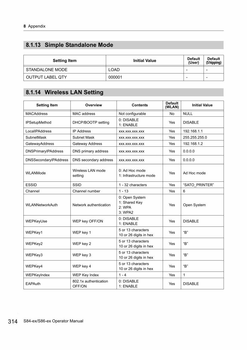
8 Appendix
314
8.1.13 Simple Standalone Mode
8.1.14 Wireless LAN Setting
Setting Item Initial Value Default(User)
Default(Shipping)
STANDALONE MODE LOAD - -
OUTPUT LABEL QTY 000001 - -
Setting Item Overview Contents Default(WLAN) Initial Value
MACAddress MAC address Not configurable No NULL
IPSetupMethod DHCP/BOOTP setting0: DISABLE1: ENABLE
Yes DISABLE
LocalIPAddress IP Address xxx.xxx.xxx.xxx Yes 192.168.1.1
SubnetMask Subnet Mask xxx.xxx.xxx.xxx Yes 255.255.255.0
GatewayAddress Gateway Address xxx.xxx.xxx.xxx Yes 192.168.1.2
DNSPrimaryIPAddress DNS primary address xxx.xxx.xxx.xxx Yes 0.0.0.0
DNSSecondaryIPAddress DNS secondary address xxx.xxx.xxx.xxx Yes 0.0.0.0
WLANModeWireless LAN mode setting
0: Ad Hoc mode1: Infrastructure mode
Yes Ad Hoc mode
ESSID SSID 1 - 32 characters Yes “SATO_PRINTER”
Channel Channel number 1 - 13 Yes 6
WLANNetworkAuth Network authentication
0: Open System1: Shared Key2: WPA3: WPA2
Yes Open System
WEPKeyUse WEP key OFF/ON0: DISABLE1: ENABLE
Yes DISABLE
WEPKey1 WEP key 15 or 13 characters10 or 26 digits in hex
Yes “B”
WEPKey2 WEP key 25 or 13 characters10 or 26 digits in hex
Yes “B”
WEPKey3 WEP key 35 or 13 characters10 or 26 digits in hex
Yes “B”
WEPKey4 WEP key 45 or 13 characters10 or 26 digits in hex
Yes “B”
WEPKeyIndex WEP Key Index 1 - 4 Yes 1
EAPAuth802.1x authentication OFF/ON
0: DISABLE1: ENABLE
Yes DISABLE
S84-ex/S86-ex Operator Manual
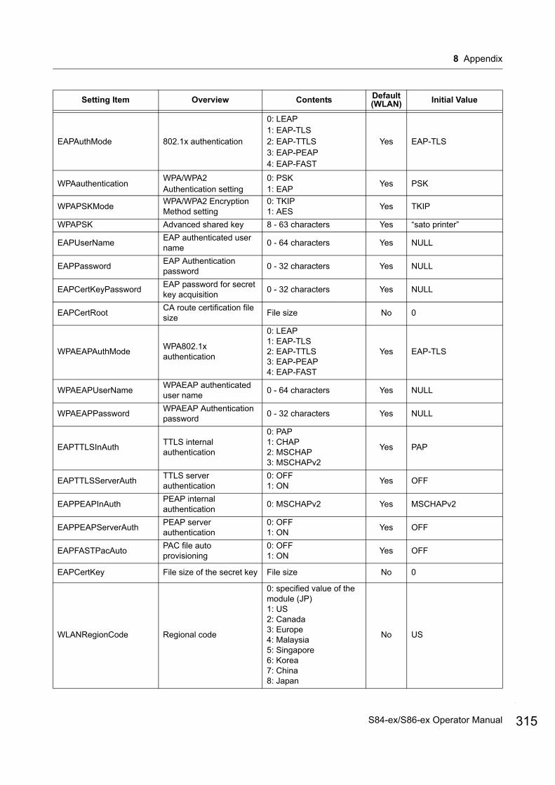
8 Appendix
EAPAuthMode 802.1x authentication
0: LEAP1: EAP-TLS2: EAP-TTLS3: EAP-PEAP4: EAP-FAST
Yes EAP-TLS
WPAauthenticationWPA/WPA2 Authentication setting
0: PSK1: EAP
Yes PSK
WPAPSKModeWPA/WPA2 Encryption Method setting
0: TKIP1: AES
Yes TKIP
WPAPSK Advanced shared key 8 - 63 characters Yes “sato printer”
EAPUserNameEAP authenticated user name
0 - 64 characters Yes NULL
EAPPasswordEAP Authentication password
0 - 32 characters Yes NULL
EAPCertKeyPasswordEAP password for secret key acquisition
0 - 32 characters Yes NULL
EAPCertRootCA route certification file size
File size No 0
WPAEAPAuthModeWPA802.1x authentication
0: LEAP1: EAP-TLS2: EAP-TTLS3: EAP-PEAP4: EAP-FAST
Yes EAP-TLS
WPAEAPUserNameWPAEAP authenticated user name
0 - 64 characters Yes NULL
WPAEAPPasswordWPAEAP Authentication password
0 - 32 characters Yes NULL
EAPTTLSInAuthTTLS internal authentication
0: PAP1: CHAP2: MSCHAP3: MSCHAPv2
Yes PAP
EAPTTLSServerAuthTTLS server authentication
0: OFF1: ON
Yes OFF
EAPPEAPInAuthPEAP internal authentication
0: MSCHAPv2 Yes MSCHAPv2
EAPPEAPServerAuthPEAP server authentication
0: OFF1: ON
Yes OFF
EAPFASTPacAutoPAC file auto provisioning
0: OFF1: ON
Yes OFF
EAPCertKey File size of the secret key File size No 0
WLANRegionCode Regional code
0: specified value of the module (JP)1: US2: Canada3: Europe4: Malaysia5: Singapore6: Korea7: China8: Japan
No US
Setting Item Overview Contents Default(WLAN) Initial Value
315S84-ex/S86-ex Operator Manual

8 Appendix
316
RoamingThresholdThreshold for roaming condition
-94 to -35 (dBm) Yes 80
AssociationThresholdThreshold for association process
-94 to -35 (dBm) Yes 85
RoamingScanWaitTimeThe time from scan end to scan start
3 - 300 (sec) Yes 300
WLANPeriodicArpInterval
ARP packet send intervals for monitoring the connection status with AP
3000 - 60000 (ms) Yes 3000
WLANBeaconLostCountDetected disconnection count number by beacon lost of the access point
1 - 60 Yes 15
EAPPreAuthEnable/Disable the EAP advanced authentication
0: DISABLE1: ENABLE
Yes DISABLE
FtpEnableLoginAccountFTP authentication method
0: OFF (No user authentication) 1: ON (User authentication)
Yes OFF
FtpLoginUser FTP login user name 1 - 32 characters Yes “guest”
FtpLoginPasswordPassword for the FTP login user
0 - 32 characters Yes “guest”
FtpDiscTimeoutDisconnected timeout time of the control connection
10 - 900 (sec) Yes 30
RawProtocol Communication protocol
0: Status 4 (cycle response)1: Status 4 (ENQ response)2: Status 3/5
Yes Status 5
RawRecvBufferSize Receive buffer size 4096 Yes 4096
RawDiscTimeout Disconnection timeout 0 - 3600 (sec) Yes 60
RawEnableDiscTimeoutENABLE/DISABLE disconnection timeout
0: DISABLE1: ENABLE
Yes ENABLE
LpdDiscTimeoutDisconnection timeout time
10 - 900 (sec) Yes 30
WebAppLoginUserWEB page login user name
0 - 63 characters Yes “admin”
WebAppLoginPasswordWEB page login password
0 - 63 characters Yes “admin”
Language Language0: Japanese1: English
Yes English
DebugMode Debug mode setting0: DISABLE1: ENABLE (log + print data)
Yes DISABLE
SignalLevel1Field intensity setting threshold 1
Absolute value from 00 to 99
Yes 85
SignalLevel2Field intensity setting threshold 2
Absolute value from 00 to 99
Yes 74
SignalLevel3Field intensity setting threshold 3
Absolute value from 00 to 99
Yes 64
Setting Item Overview Contents Default(WLAN) Initial Value
S84-ex/S86-ex Operator Manual
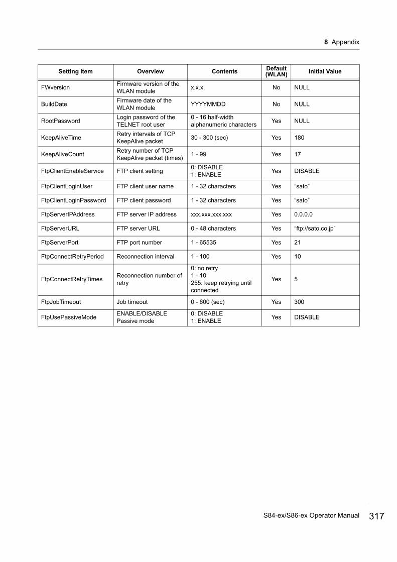
8 Appendix
FWversionFirmware version of the WLAN module
x.x.x. No NULL
BuildDateFirmware date of the WLAN module
YYYYMMDD No NULL
RootPasswordLogin password of the TELNET root user
0 - 16 half-width alphanumeric characters
Yes NULL
KeepAliveTimeRetry intervals of TCP KeepAlive packet
30 - 300 (sec) Yes 180
KeepAliveCountRetry number of TCP KeepAlive packet (times)
1 - 99 Yes 17
FtpClientEnableService FTP client setting0: DISABLE1: ENABLE
Yes DISABLE
FtpClientLoginUser FTP client user name 1 - 32 characters Yes “sato”
FtpClientLoginPassword FTP client password 1 - 32 characters Yes “sato”
FtpServerIPAddress FTP server IP address xxx.xxx.xxx.xxx Yes 0.0.0.0
FtpServerURL FTP server URL 0 - 48 characters Yes “ftp://sato.co.jp”
FtpServerPort FTP port number 1 - 65535 Yes 21
FtpConnectRetryPeriod Reconnection interval 1 - 100 Yes 10
FtpConnectRetryTimesReconnection number of retry
0: no retry1 - 10255: keep retrying until connected
Yes 5
FtpJobTimeout Job timeout 0 - 600 (sec) Yes 300
FtpUsePassiveModeENABLE/DISABLE Passive mode
0: DISABLE1: ENABLE
Yes DISABLE
Setting Item Overview Contents Default(WLAN) Initial Value
317S84-ex/S86-ex Operator Manual
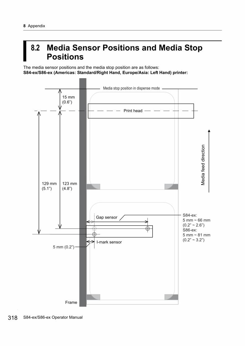
8 Appendix
318
8.2 Media Sensor Positions and Media Stop Positions
The media sensor positions and the media stop position are as follows:S84-ex/S86-ex (Americas: Standard/Right Hand, Europe/Asia: Left Hand) printer:
I-mark sensor
Med
ia fe
ed d
irect
ion
Media stop position in dispense mode
Gap sensor
Frame
Print head
123 mm(4.8”)
15 mm(0.6”)
5 mm (0.2”)
S84-ex:5 mm ~ 66 mm(0.2” ~ 2.6”)S86-ex:5 mm ~ 81 mm(0.2” ~ 3.2”)
129 mm(5.1”)
I-mark sensor
Gap sensor
Print head
Med
ia fe
ed d
irect
ion
S84-ex/S86-ex Operator Manual
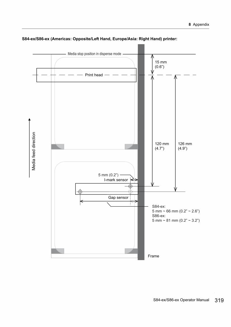
8 Appendix
S84-ex/S86-ex (Americas: Opposite/Left Hand, Europe/Asia: Right Hand) printer:
I-mark sensor
Med
ia fe
ed d
irect
ion
Gap sensor
Frame
Print head
120 mm(4.7”)
15 mm(0.6”)
5 mm (0.2”)
S84-ex:5 mm ~ 66 mm (0.2” ~ 2.6”)S86-ex:5 mm ~ 81 mm (0.2” ~ 3.2”)
126 mm(4.9”)
Media stop position in dispense mode
I-mark sensor
Gap sensor
Print head
Med
ia fe
ed d
irect
ion
319S84-ex/S86-ex Operator Manual
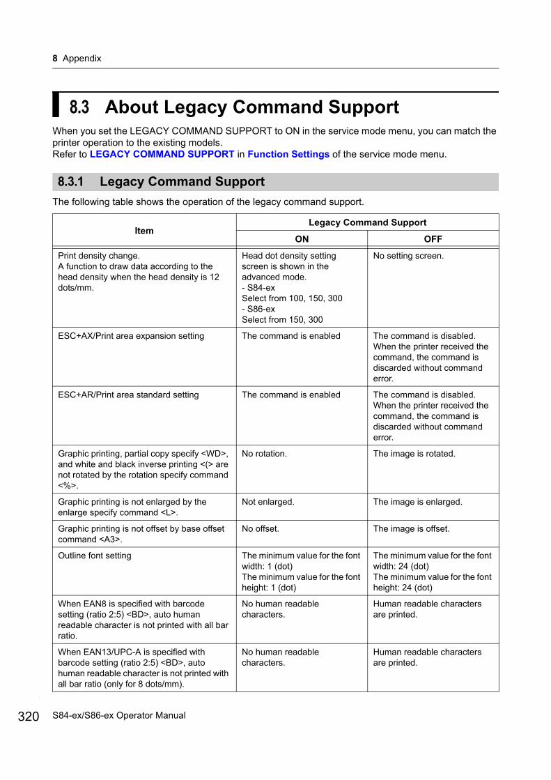
8 Appendix
320
8.3 About Legacy Command SupportWhen you set the LEGACY COMMAND SUPPORT to ON in the service mode menu, you can match the printer operation to the existing models.Refer to LEGACY COMMAND SUPPORT in Function Settings of the service mode menu.
8.3.1 Legacy Command Support
The following table shows the operation of the legacy command support.
ItemLegacy Command Support
ON OFF
Print density change.A function to draw data according to the head density when the head density is 12 dots/mm.
Head dot density setting screen is shown in the advanced mode.- S84-exSelect from 100, 150, 300- S86-exSelect from 150, 300
No setting screen.
ESC+AX/Print area expansion setting The command is enabled The command is disabled.When the printer received the command, the command is discarded without command error.
ESC+AR/Print area standard setting The command is enabled The command is disabled.When the printer received the command, the command is discarded without command error.
Graphic printing, partial copy specify <WD>, and white and black inverse printing <(> are not rotated by the rotation specify command <%>.
No rotation. The image is rotated.
Graphic printing is not enlarged by the enlarge specify command <L>.
Not enlarged. The image is enlarged.
Graphic printing is not offset by base offset command <A3>.
No offset. The image is offset.
Outline font setting The minimum value for the font width: 1 (dot)The minimum value for the font height: 1 (dot)
The minimum value for the font width: 24 (dot)The minimum value for the font height: 24 (dot)
When EAN8 is specified with barcode setting (ratio 2:5) <BD>, auto human readable character is not printed with all bar ratio.
No human readable characters.
Human readable characters are printed.
When EAN13/UPC-A is specified with barcode setting (ratio 2:5) <BD>, auto human readable character is not printed with all bar ratio (only for 8 dots/mm).
No human readable characters.
Human readable characters are printed.
S84-ex/S86-ex Operator Manual
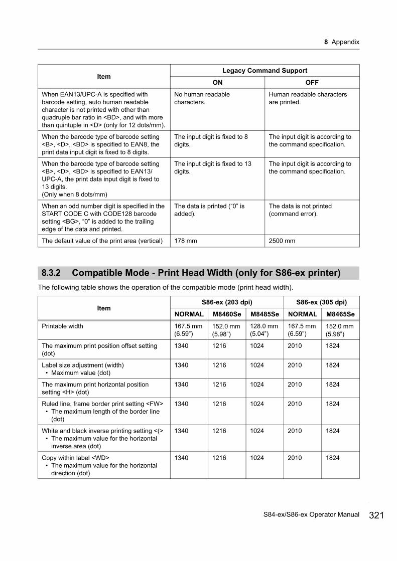
8 Appendix
8.3.2 Compatible Mode - Print Head Width (only for S86-ex printer)
The following table shows the operation of the compatible mode (print head width).
When EAN13/UPC-A is specified with barcode setting, auto human readable character is not printed with other than quadruple bar ratio in <BD>, and with more than quintuple in <D> (only for 12 dots/mm).
No human readable characters.
Human readable characters are printed.
When the barcode type of barcode setting <B>, <D>, <BD> is specified to EAN8, the print data input digit is fixed to 8 digits.
The input digit is fixed to 8 digits.
The input digit is according to the command specification.
When the barcode type of barcode setting <B>, <D>, <BD> is specified to EAN13/UPC-A, the print data input digit is fixed to 13 digits. (Only when 8 dots/mm)
The input digit is fixed to 13 digits.
The input digit is according to the command specification.
When an odd number digit is specified in the START CODE C with CODE128 barcode setting <BG>, “0” is added to the trailing edge of the data and printed.
The data is printed (“0” is added).
The data is not printed (command error).
The default value of the print area (vertical) 178 mm 2500 mm
ItemS86-ex (203 dpi) S86-ex (305 dpi)
NORMAL M8460Se M8485Se NORMAL M8465Se
Printable width 167.5 mm (6.59”)
152.0 mm (5.98”)
128.0 mm (5.04”)
167.5 mm (6.59”)
152.0 mm (5.98”)
The maximum print position offset setting (dot)
1340 1216 1024 2010 1824
Label size adjustment (width)• Maximum value (dot)
1340 1216 1024 2010 1824
The maximum print horizontal position setting <H> (dot)
1340 1216 1024 2010 1824
Ruled line, frame border print setting <FW>• The maximum length of the border line
(dot)
1340 1216 1024 2010 1824
White and black inverse printing setting <(>• The maximum value for the horizontal
inverse area (dot)
1340 1216 1024 2010 1824
Copy within label <WD>• The maximum value for the horizontal
direction (dot)
1340 1216 1024 2010 1824
ItemLegacy Command Support
ON OFF
321S84-ex/S86-ex Operator Manual

8 Appendix
322
Mirror rotation setting <RM>• The maximum value for the horizontal
direction (dot)
1340 1216 1024 2010 1824
Graphics print <G>• The maximum byte for the horizontal
direction
168 152 128 252 228
Media size <A1>• The maximum label width (dot)
1340 1216 1024 2010 1824
Base offset setting <A3>• The maximum value for the horizontal
direction offset (dot)
1340 1216 1024 2010 1824
Printer operation register setting <PG>• The maximum label width (dot)
1340 1216 1024 2010 1824
Printer operation register setting <PC>• The maximum label width (dot)
1340 1216 1024 2010 1824
Form overlay registration <&S>• The maximum horizontal direction
available range (dot)
1340 1216 1024 2010 1824
Graphics registration <GI>• The maximum byte for the horizontal
direction
168 152 128 252 228
Print configuration request <SOH+MG>• The maximum label width (dot)
1340 1216 1024 2010 1824
Print configuration request <SOH+MG>• The maximum offset value for the
horizontal base point (dot)
1340 1216 1024 2010 1824
ItemS86-ex (203 dpi) S86-ex (305 dpi)
NORMAL M8460Se M8485Se NORMAL M8465Se
S84-ex/S86-ex Operator Manual

8 Appendix
8.3.3 Print Head Width and Printable Area Range
Print head width and printable width
Print Head Density
S86-ex M8460Se/M8465Se M8485Se
Print Head Width
Printable Width
Print Head Width
Printable Width
Print Head Width
Printable Width
8 dots/mm (203 dpi) 168 mm (6.61”)
167.5 mm (6.59”)
152 mm (5.98”)
152 mm (5.98”)
128 mm (5.04”)
128 mm (5.04”)
12 dots/mm (305 dpi) 167.9 mm (6.61”)
167.5 mm (6.59”)
154.7 mm (6.09”)
152 mm (5.98”)
- -
Med
ia fe
ed d
irect
ion
Base reference point for printing
S86-ex(203dpi)M8460Se compatible
M8460Se
M8485Se
M8465Se compatibleM8465Se
Frame
168.0 mm
152.0 mm
128.0 mm
167.9 mm
154.7 mm
3.0 mm
Printable width(M8485Se compatible)
128.0 mm
Printable width(M846xSe compatible)
152.0 mmPrintable width167.5 mm
S86-ex(305dpi)
M8485Se compatible
Base reference point for printing
168.0 mm
152.0 mm
128.0 mm
167.9 mm
154.7 mm
3.0 mm
Printable width(M8485Se compatible)
128.0 mm
Printable width(M846xSe compatible)
152.0 mmPrintable width167.5 mm
S86-ex(203dpi)M8460Se compatible
M8460Se
M8485Se
M8465Se compatibleM8465Se
S86-ex(305dpi)
M8485Se compatible
Frame
S86-ex (Americas: Opposite/Left Hand, Europe/Asia: Right Hand) printer
S86-ex (Americas: Standard/Right Hand,Europe/Asia: Left Hand) printer
323S84-ex/S86-ex Operator Manual
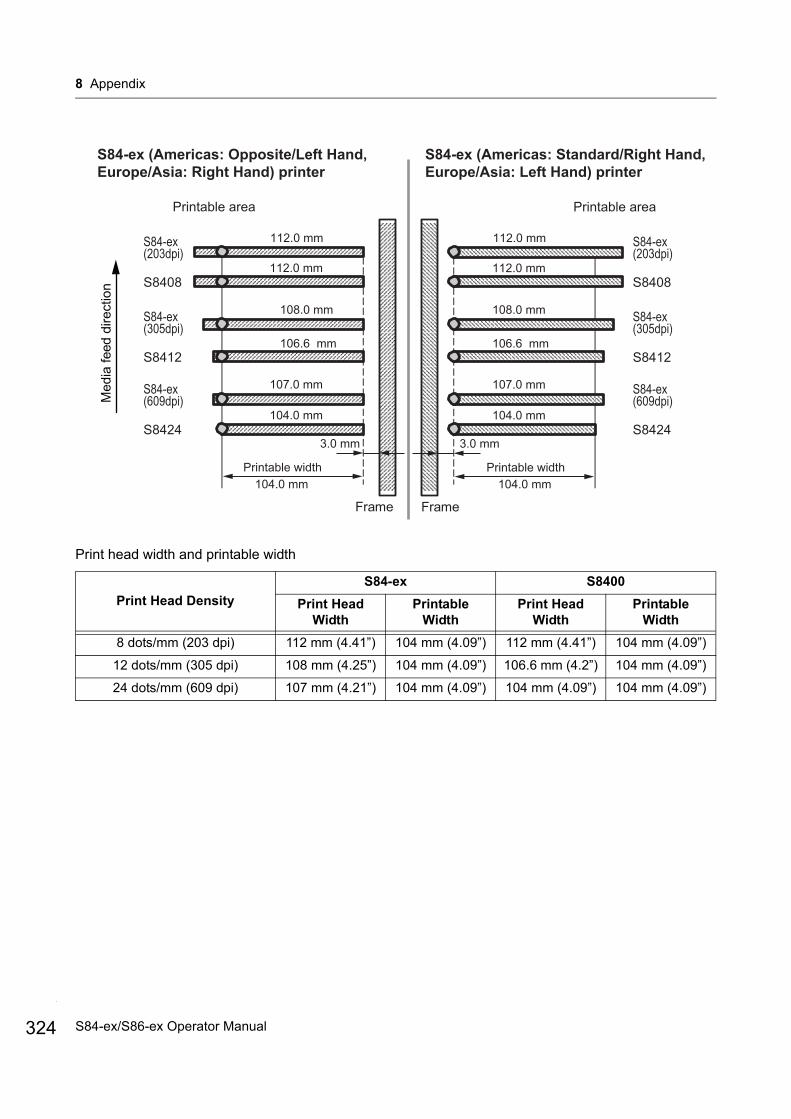
8 Appendix
324
Print head width and printable width
Print Head Density
S84-ex S8400
Print Head Width
Printable Width
Print Head Width
Printable Width
8 dots/mm (203 dpi) 112 mm (4.41”) 104 mm (4.09”) 112 mm (4.41”) 104 mm (4.09”)
12 dots/mm (305 dpi) 108 mm (4.25”) 104 mm (4.09”) 106.6 mm (4.2”) 104 mm (4.09”)
24 dots/mm (609 dpi) 107 mm (4.21”) 104 mm (4.09”) 104 mm (4.09”) 104 mm (4.09”)
Med
ia fe
ed d
irect
ion
Frame
S84-ex (Americas: Opposite/Left Hand, Europe/Asia: Right Hand) printer
S84-ex (Americas: Standard/Right Hand,Europe/Asia: Left Hand) printer
Printable area
112.0 mm
112.0 mm
108.0 mm
106.6 mm
107.0 mm
104.0 mm
3.0 mm
Printable width104.0 mm
S84-ex(203dpi)
S8408
S84-ex(305dpi)
S8412
S84-ex(609dpi)
S8424
Frame
Printable area
112.0 mm
112.0 mm
108.0 mm
106.6 mm
107.0 mm
104.0 mm
3.0 mm
Printable width104.0 mm
S84-ex(203dpi)
S8408
S84-ex(305dpi)
S8412
S84-ex(609dpi)
S8424
S84-ex/S86-ex Operator Manual

8 Appendix
8.4 LCD Power Saving ModeThis function is designed to reduce power consumption by setting the LCD backlight to off when the printer is not operated for a specified period of time. The time required for the LCD backlight to light off can be set at LCD POWER SAVING setting screen in the advanced mode.Refer to Section 4.2.13 Advanced Mode for the flowchart to access the setting. The setting procedure of the LCD power saving mode is as follows:
1 In offline mode, press the ENTER button.The printer changes to setting mode menu.
2 Select the ADVANCED MODE using the / / / buttons and then press the ENTER button.
3 Press the ENTER button again until LCD POWER SAVING shows on the screen.
4 Press the / buttons to select a value.The setting range is from 00 to 15 MIN.When “00” is selected, this function is disabled and the LCD backlight is always on.
5 Press the ENTER button to save the setting.
Conditions to set the LCD backlight to offUnder the following conditions, the LCD backlight lights off when the time specified on the LCD POWER SAVING setting screen has elapsed. With this function, only the LCD backlight lights off and the on-screen message remains the same.
• The printer has not received the print data* (ESC+A to ESC+Z) in various interfaces.* Each protocol’s status return request, cancel request and incorrect data are omitted.
• No button is pressed.• The printer is not in error mode.• The printer is neither printing nor feeding media.• The printer is in online mode, offline mode or hex dump mode.
This function is disabled in download mode.
Conditions to set the LCD backlight to onAny of the following conditions will light the LCD backlight on again.
• The printer receives the print data* from various interfaces.* Each protocol’s status return request, cancel request and incorrect data are omitted.
• Any button on the operator panel is pressed.• Printer error such as “Head open” occurs.• The printer starts the printing operation.
Pressing any button while the LCD backlight is off will only light the LCD backlight back on. The function of the button is invalid.(For example, the printer does not go offline by pressing the LINE button when the LCD backlight is off in online mode.)
325S84-ex/S86-ex Operator Manual
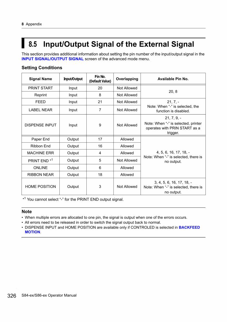
8 Appendix
326
8.5 Input/Output Signal of the External SignalThis section provides additional information about setting the pin number of the input/output signal in the INPUT SIGNAL/OUTPUT SIGNAL screen of the advanced mode menu.
Setting Conditions
*1 You cannot select “-” for the PRINT END output signal.
Note• When multiple errors are allocated to one pin, the signal is output when one of the errors occurs.• All errors need to be released in order to switch the signal output back to normal.• DISPENSE INPUT and HOME POSITION are available only if CONTROLED is selected in BACKFEED
MOTION.
Signal Name Input/OutputPin No.
(Default Value)Overlapping Available Pin No.
PRINT START Input 20 Not Allowed20, 8
Reprint Input 8 Not Allowed
FEED Input 21 Not Allowed 21, 7, -Note: When “-” is selected, the
function is disabled.LABEL NEAR Input 7 Not Allowed
DISPENSE INPUT Input 9 Not Allowed
21, 7, 9, -
Note: When “-” is selected, printer operates with PRIN START as a
trigger.
Paper End Output 17 Allowed
4, 5, 6, 16, 17, 18, -Note: When “-” is selected, there is
no output.
Ribbon End Output 16 Allowed
MACHINE ERR Output 4 Allowed
PRINT END *1 Output 5 Not Allowed
ONLINE Output 6 Allowed
RIBBON NEAR Output 18 Allowed
HOME POSITION Output 3 Not Allowed3, 4, 5, 6, 16, 17, 18, -
Note: When “-” is selected, there is no output.
S84-ex/S86-ex Operator Manual
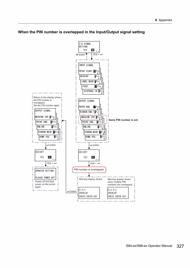
8 Appendix
When the PIN number is overlapped in the Input/Output signal setting
button
button
YES +
YES +
Power off and then power on the printer again .
button
Same PIN number is set.
PIN number is overlapped.
Return to the display where the PIN number is overlapped.Set the PIN number again.
button
YES +
Warning display shows. Warning display shows when multiple PIN numbers are overlapped.
327S84-ex/S86-ex Operator Manual
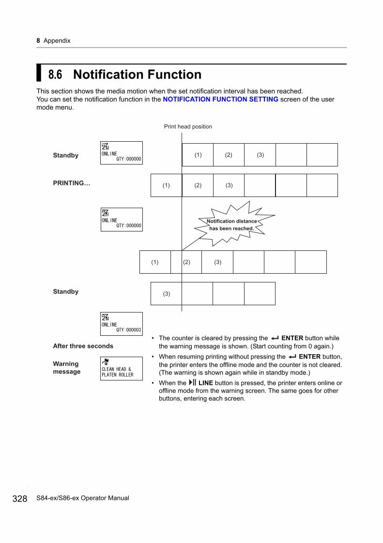
8 Appendix
328
8.6 Notification FunctionThis section shows the media motion when the set notification interval has been reached. You can set the notification function in the NOTIFICATION FUNCTION SETTING screen of the user mode menu.
Print head position
Standby
PRINTING…
Standby
After three seconds
Warningmessage
(1) (2) (3)
(1) (2) (3)
(1) (2) (3)
Notification distance has been reached.
(3)
• The counter is cleared by pressing the ENTER button while the warning message is shown. (Start counting from 0 again.)
• When resuming printing without pressing the ENTER button, the printer enters the offline mode and the counter is not cleared. (The warning is shown again while in standby mode.)
• When the LINE button is pressed, the printer enters online or offline mode from the warning screen. The same goes for other buttons, entering each screen.
S84-ex/S86-ex Operator Manual
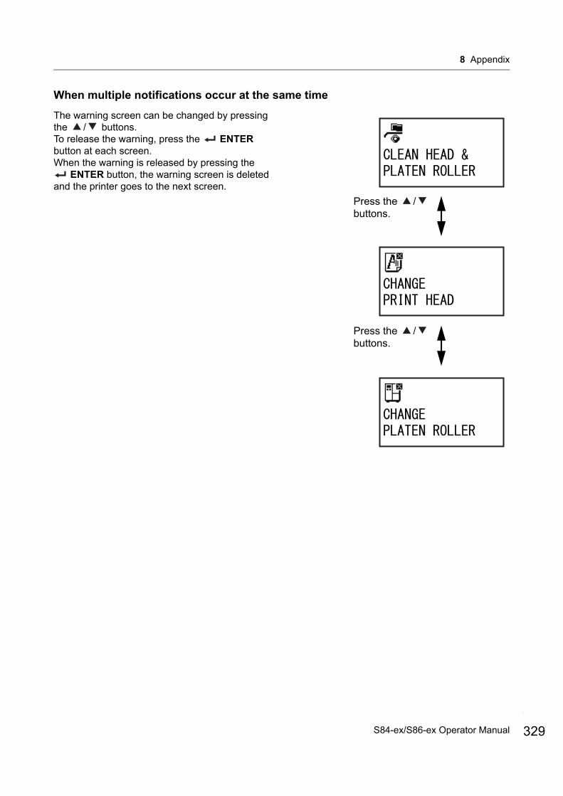
8 Appendix
When multiple notifications occur at the same time
The warning screen can be changed by pressing the / buttons.To release the warning, press the ENTER button at each screen.When the warning is released by pressing the
ENTER button, the warning screen is deleted and the printer goes to the next screen.
Press the / buttons.
Press the / buttons.
329S84-ex/S86-ex Operator Manual
8 Appendix
330
8.7 Replacing Consumable PartsSome consumable parts, such as the print head and platen roller, will wear out over time and can be replaced easily. This section describes the procedures to replace these parts.
Note• Use only SATO genuine consumable parts for replacement.
Contact your SATO reseller or technical support center for parts ordering information.• Regular cleaning may extend the life span of some print heads and platen rollers. Refer to Section 6.2
Maintenance of the Print Head and Platen Roller for details.
8.7.1 Replacing the Print Head
You can easily remove and replace a damaged or worn print head.
Before replacementPerform a factory test print and check the head counter.
WARNING• Do not touch the power switch, connect or disconnect the power cord while your hands are wet. Doing so
could cause an electric shock.• Disconnect the power cord from the AC outlet before you replace the print head.• Wear gloves before replacing the print head, to prevent damage to the print head.
1 Make sure that the printer is in power off mode, then disconnect the power cord from the AC outlet.
2 Open the top cover.
CAUTIONOpen the top cover fully to prevent accidental drop of the cover.
S84-ex/S86-ex Operator Manual
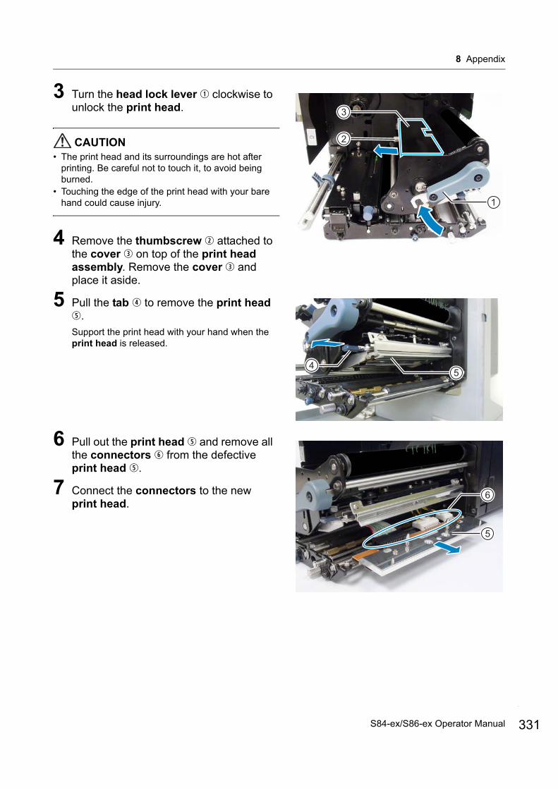
8 Appendix
3 Turn the head lock lever clockwise to unlock the print head.
CAUTION• The print head and its surroundings are hot after
printing. Be careful not to touch it, to avoid being burned.
• Touching the edge of the print head with your bare hand could cause injury.
4 Remove the thumbscrew attached to the cover on top of the print head assembly. Remove the cover and place it aside.
5 Pull the tab to remove the print head .Support the print head with your hand when the print head is released.
6 Pull out the print head and remove all the connectors from the defective print head .
7 Connect the connectors to the new print head.
1
2
3
45
5
6
331S84-ex/S86-ex Operator Manual
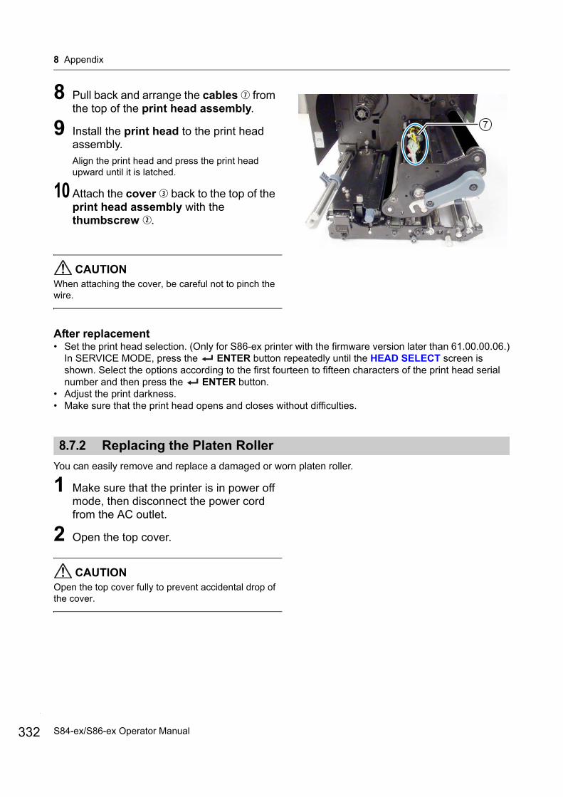
8 Appendix
332
8 Pull back and arrange the cables from the top of the print head assembly.
9 Install the print head to the print head assembly.Align the print head and press the print head upward until it is latched.
10 Attach the cover back to the top of the print head assembly with the thumbscrew .
CAUTIONWhen attaching the cover, be careful not to pinch the wire.
After replacement• Set the print head selection. (Only for S86-ex printer with the firmware version later than 61.00.00.06.)
In SERVICE MODE, press the ENTER button repeatedly until the HEAD SELECT screen is shown. Select the options according to the first fourteen to fifteen characters of the print head serial number and then press the ENTER button.
• Adjust the print darkness.• Make sure that the print head opens and closes without difficulties.
8.7.2 Replacing the Platen Roller
You can easily remove and replace a damaged or worn platen roller.
1 Make sure that the printer is in power off mode, then disconnect the power cord from the AC outlet.
2 Open the top cover.
CAUTIONOpen the top cover fully to prevent accidental drop of the cover.
7
S84-ex/S86-ex Operator Manual
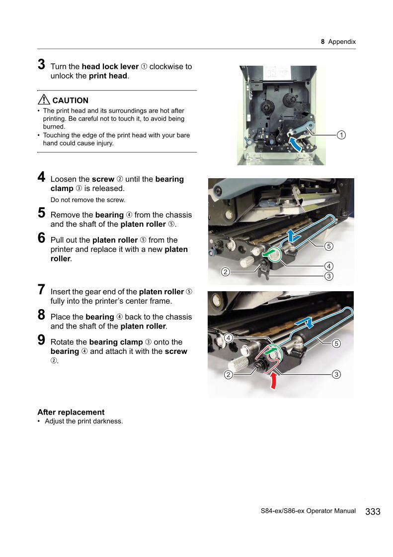
8 Appendix
3 Turn the head lock lever clockwise to unlock the print head.
CAUTION• The print head and its surroundings are hot after
printing. Be careful not to touch it, to avoid being burned.
• Touching the edge of the print head with your bare hand could cause injury.
4 Loosen the screw until the bearing clamp is released.Do not remove the screw.
5 Remove the bearing from the chassis and the shaft of the platen roller .
6 Pull out the platen roller from the printer and replace it with a new platen roller.
7 Insert the gear end of the platen roller fully into the printer’s center frame.
8 Place the bearing back to the chassis and the shaft of the platen roller.
9 Rotate the bearing clamp onto the bearing and attach it with the screw .
After replacement• Adjust the print darkness.
1
432
5
5
32
4
333S84-ex/S86-ex Operator Manual

8 Appendix
334
8.7.3 Replacing the Pressure Roller
You can easily remove and replace a damaged or worn pressure roller.
1 Make sure that the printer is in power off mode, then disconnect the power cord from the AC outlet.
2 Open the top cover.
CAUTIONOpen the top cover fully to prevent accidental drop of the cover.
3 Turn the head lock lever clockwise to unlock the print head.
CAUTION• The print head and its surroundings are hot after
printing. Be careful not to touch it, to avoid being burned.
• Touching the edge of the print head with your bare hand could cause injury.
4 Push the pressure roller release tab up to release the pressure roller plate .
5 Loosen the screw until the bearing clamp is released.Do not remove the screw.
6 Remove the bearing from the chassis and the shaft of the pressure roller .
7 Pull out the pressure roller from the printer and replace it with a new pressure roller.
1
5
6
32
47
S84-ex/S86-ex Operator Manual
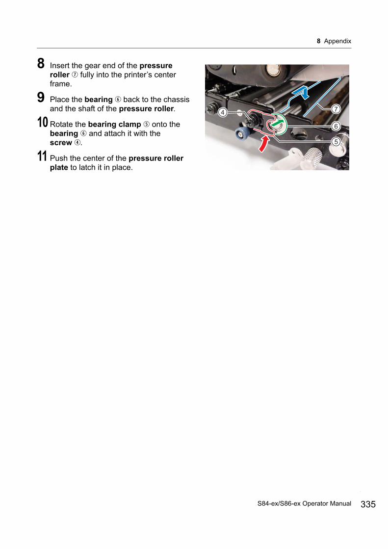
8 Appendix
8 Insert the gear end of the pressure roller fully into the printer’s center frame.
9 Place the bearing back to the chassis and the shaft of the pressure roller.
10 Rotate the bearing clamp onto the bearing and attach it with the screw .
11 Push the center of the pressure roller plate to latch it in place.
7
5
6
4
335S84-ex/S86-ex Operator Manual

8 Appendix
336
8.7.4 Replacing the Media Feed Roller
You can easily remove and replace a damaged or worn media feed roller.
1 Make sure that the printer is in power off mode, then disconnect the power cord from the AC outlet.
2 Open the top cover.
CAUTIONOpen the top cover fully to prevent accidental drop of the cover.
3 Turn the head lock lever clockwise to unlock the print head.
CAUTION• The print head and its surroundings are hot after
printing. Be careful not to touch it, to avoid being burned.
• Touching the edge of the print head with your bare hand could cause injury.
4 Pull the feed lock latch to unlock the feed roller and media sensor assembly .The feed roller and media sensor assembly will flip open.
5 Loosen the screw until the bearing clamp is released.Do not remove the screw.
6 Remove the bearing from the chassis and the shaft of the media feed roller .
7 Pull out the media feed roller from the printer and replace it with a new media feed roller.
1
2
3
654
7
S84-ex/S86-ex Operator Manual

8 Appendix
8 Insert the gear end of the new media feed roller fully into the printer’s center frame.
9 Place the bearing back to the chassis and the shaft of the media feed roller.
10 Rotate the bearing clamp onto the bearing and attach it with the screw .
8.7.5 Replacing the Fan Filter
The fan filter prevents atmospheric debris from being drawn into the printer.
1 Peel off the old fan filter from the rear of the printer.
2 Clean the printer to remove any adhesive residue on the surface.
NoteYou can purchase a cleaning kit from a SATO reseller or technical service center.
3 Remove the backing paper from the new fan filter and paste the fan filter over the fan exhaust holes.
7
5
4
6
1
337S84-ex/S86-ex Operator Manual
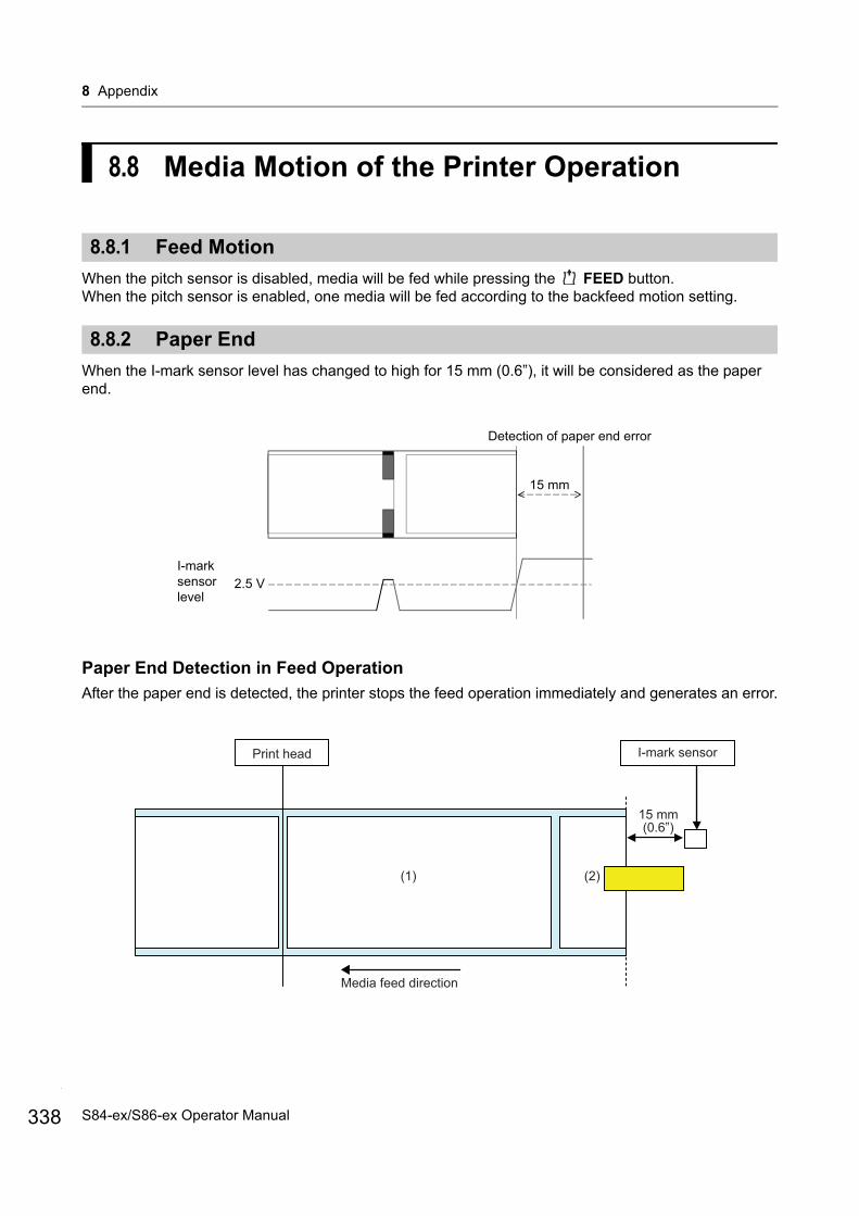
8 Appendix
338
8.8 Media Motion of the Printer Operation
8.8.1 Feed Motion
When the pitch sensor is disabled, media will be fed while pressing the FEED button. When the pitch sensor is enabled, one media will be fed according to the backfeed motion setting.
8.8.2 Paper End
When the I-mark sensor level has changed to high for 15 mm (0.6”), it will be considered as the paper end.
Paper End Detection in Feed Operation
After the paper end is detected, the printer stops the feed operation immediately and generates an error.
15 mm
Detection of paper end error
2.5 VI-mark sensor level
Media feed direction
Print head I-mark sensor
15 mm (0.6”)
(1) (2)
S84-ex/S86-ex Operator Manual
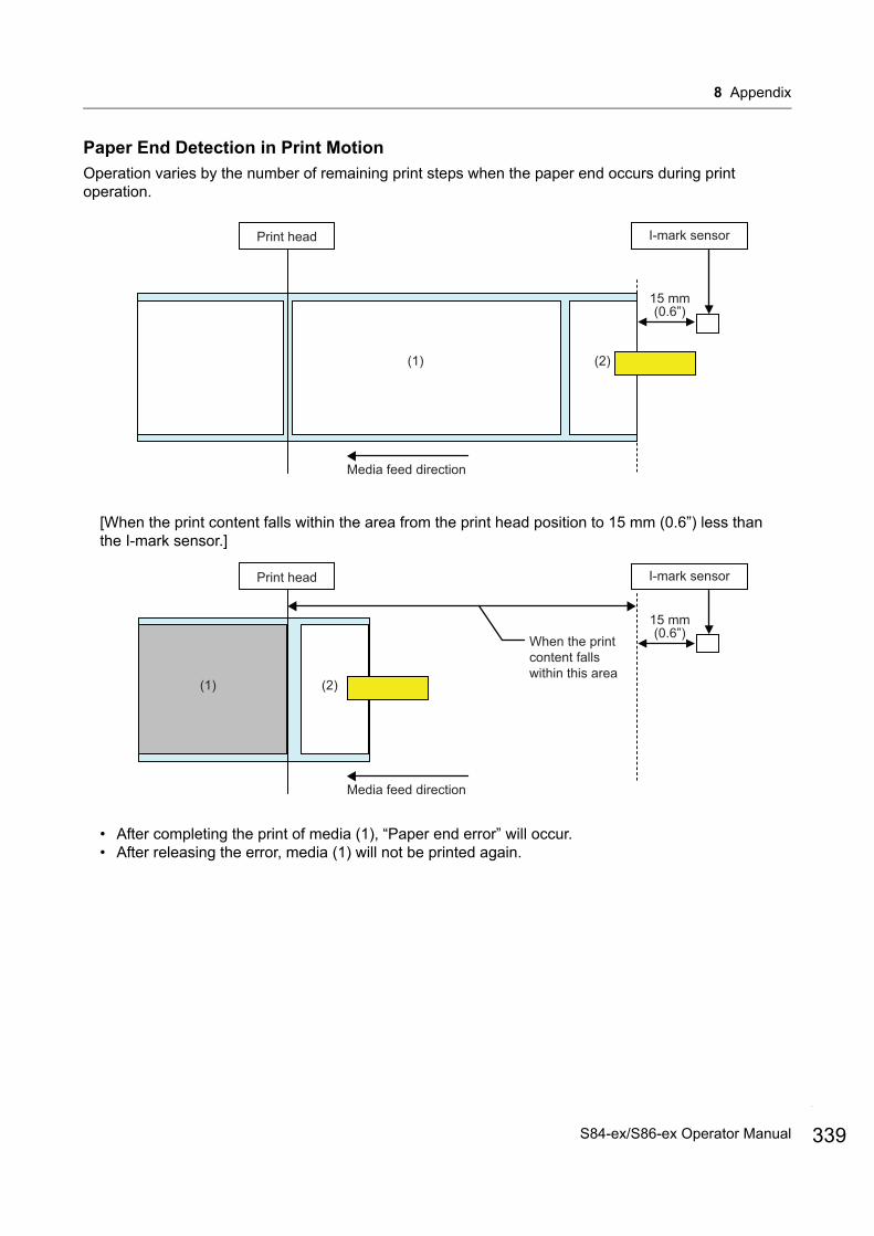
8 Appendix
Paper End Detection in Print Motion
Operation varies by the number of remaining print steps when the paper end occurs during print operation.
[When the print content falls within the area from the print head position to 15 mm (0.6”) less than the I-mark sensor.]
• After completing the print of media (1), “Paper end error” will occur.• After releasing the error, media (1) will not be printed again.
Media feed direction
Print head I-mark sensor
15 mm (0.6”)
(1) (2)
Media feed direction
Print head I-mark sensor
15 mm (0.6”)
(1) (2)
When the print content falls within this area
339S84-ex/S86-ex Operator Manual
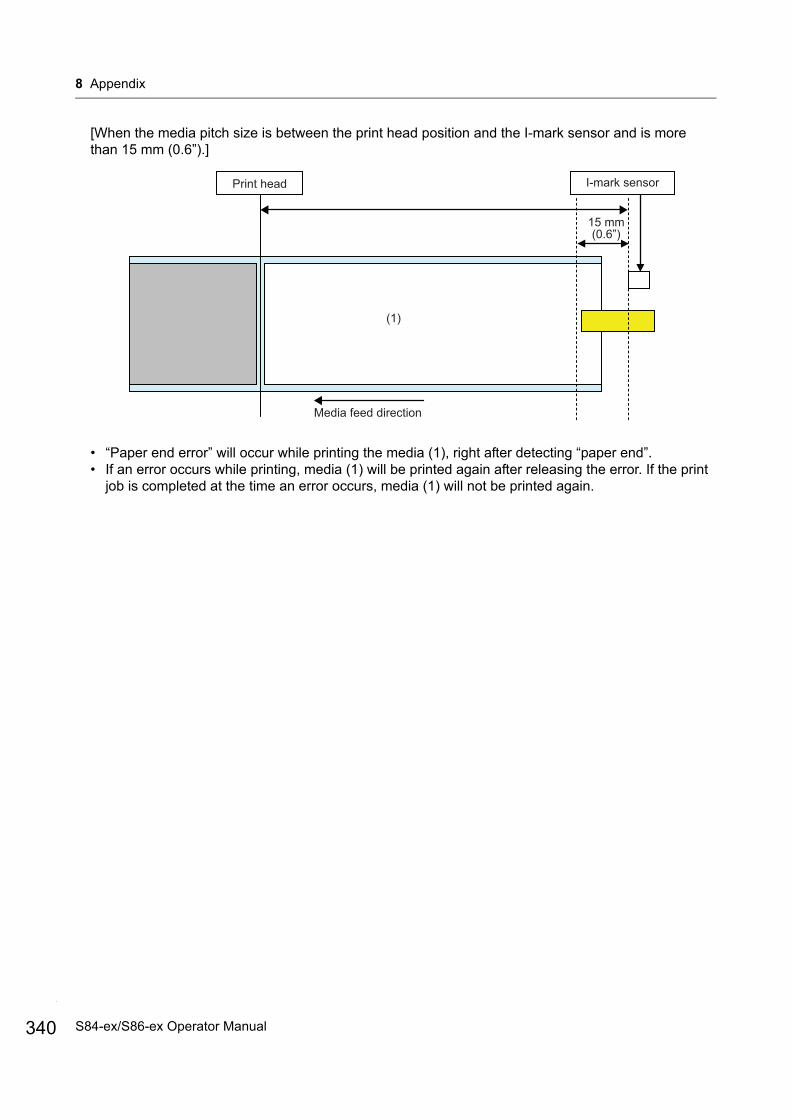
8 Appendix
340
[When the media pitch size is between the print head position and the I-mark sensor and is more than 15 mm (0.6”).]
• “Paper end error” will occur while printing the media (1), right after detecting “paper end”.• If an error occurs while printing, media (1) will be printed again after releasing the error. If the print
job is completed at the time an error occurs, media (1) will not be printed again.
(1)
Media feed direction
Print head I-mark sensor
15 mm (0.6”)
S84-ex/S86-ex Operator Manual
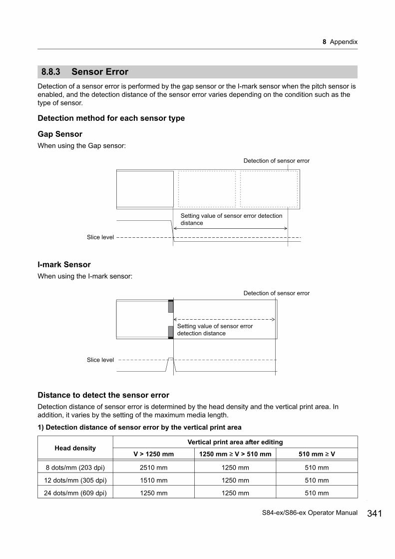
8 Appendix
8.8.3 Sensor Error
Detection of a sensor error is performed by the gap sensor or the I-mark sensor when the pitch sensor is enabled, and the detection distance of the sensor error varies depending on the condition such as the type of sensor.
Detection method for each sensor type
Gap Sensor
When using the Gap sensor:
I-mark Sensor
When using the I-mark sensor:
Distance to detect the sensor error
Detection distance of sensor error is determined by the head density and the vertical print area. In addition, it varies by the setting of the maximum media length.
1) Detection distance of sensor error by the vertical print area
Head densityVertical print area after editing
V > 1250 mm 1250 mm ≥ V > 510 mm 510 mm ≥ V
8 dots/mm (203 dpi) 2510 mm 1250 mm 510 mm
12 dots/mm (305 dpi) 1510 mm 1250 mm 510 mm
24 dots/mm (609 dpi) 1250 mm 1250 mm 510 mm
Detection of sensor error
Slice level
Setting value of sensor error detection distance
Detection of sensor error
Slice level
Setting value of sensor error detection distance
341S84-ex/S86-ex Operator Manual
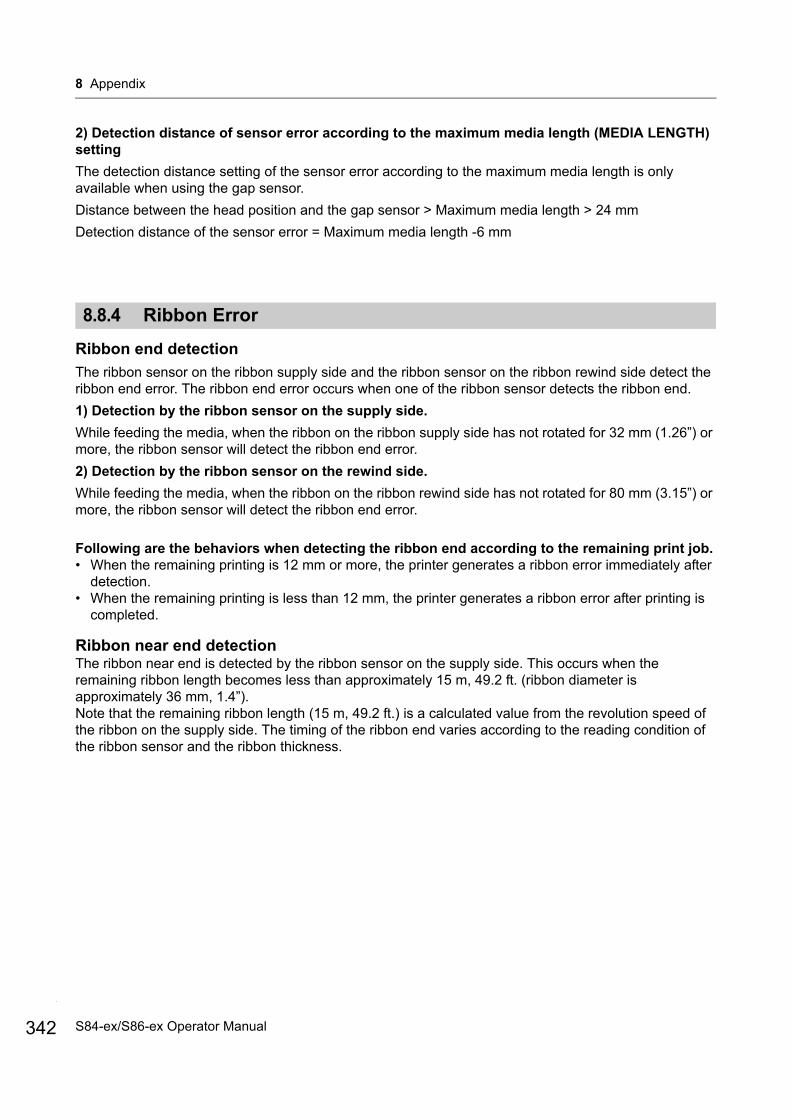
8 Appendix
342
2) Detection distance of sensor error according to the maximum media length (MEDIA LENGTH) setting
The detection distance setting of the sensor error according to the maximum media length is only available when using the gap sensor.
Distance between the head position and the gap sensor > Maximum media length > 24 mm
Detection distance of the sensor error = Maximum media length -6 mm
8.8.4 Ribbon Error
Ribbon end detection
The ribbon sensor on the ribbon supply side and the ribbon sensor on the ribbon rewind side detect the ribbon end error. The ribbon end error occurs when one of the ribbon sensor detects the ribbon end.
1) Detection by the ribbon sensor on the supply side.
While feeding the media, when the ribbon on the ribbon supply side has not rotated for 32 mm (1.26”) or more, the ribbon sensor will detect the ribbon end error.
2) Detection by the ribbon sensor on the rewind side.
While feeding the media, when the ribbon on the ribbon rewind side has not rotated for 80 mm (3.15”) or more, the ribbon sensor will detect the ribbon end error.
Following are the behaviors when detecting the ribbon end according to the remaining print job.• When the remaining printing is 12 mm or more, the printer generates a ribbon error immediately after
detection.• When the remaining printing is less than 12 mm, the printer generates a ribbon error after printing is
completed.
Ribbon near end detectionThe ribbon near end is detected by the ribbon sensor on the supply side. This occurs when the remaining ribbon length becomes less than approximately 15 m, 49.2 ft. (ribbon diameter is approximately 36 mm, 1.4”).Note that the remaining ribbon length (15 m, 49.2 ft.) is a calculated value from the revolution speed of the ribbon on the supply side. The timing of the ribbon end varies according to the reading condition of the ribbon sensor and the ribbon thickness.
S84-ex/S86-ex Operator Manual
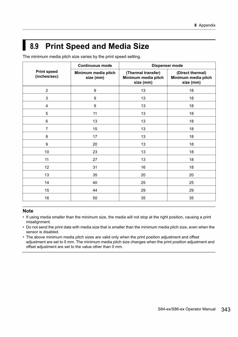
8 Appendix
8.9 Print Speed and Media SizeThe minimum media pitch size varies by the print speed setting.
Note• If using media smaller than the minimum size, the media will not stop at the right position, causing a print
misalignment.• Do not send the print data with media size that is smaller than the minimum media pitch size, even when the
sensor is disabled.• The above minimum media pitch sizes are valid only when the print position adjustment and offset
adjustment are set to 0 mm. The minimum media pitch size changes when the print position adjustment and offset adjustment are set to the value other than 0 mm.
Print speed(inches/sec)
Continuous mode Dispenser mode
Minimum media pitch size (mm)
(Thermal transfer)Minimum media pitch
size (mm)
(Direct thermal)Minimum media pitch
size (mm)
2 9 13 18
3 9 13 18
4 9 13 18
5 11 13 18
6 13 13 18
7 15 13 18
8 17 13 18
9 20 13 18
10 23 13 18
11 27 13 18
12 31 16 18
13 35 20 20
14 40 25 25
15 44 29 29
16 50 35 35
343S84-ex/S86-ex Operator Manual
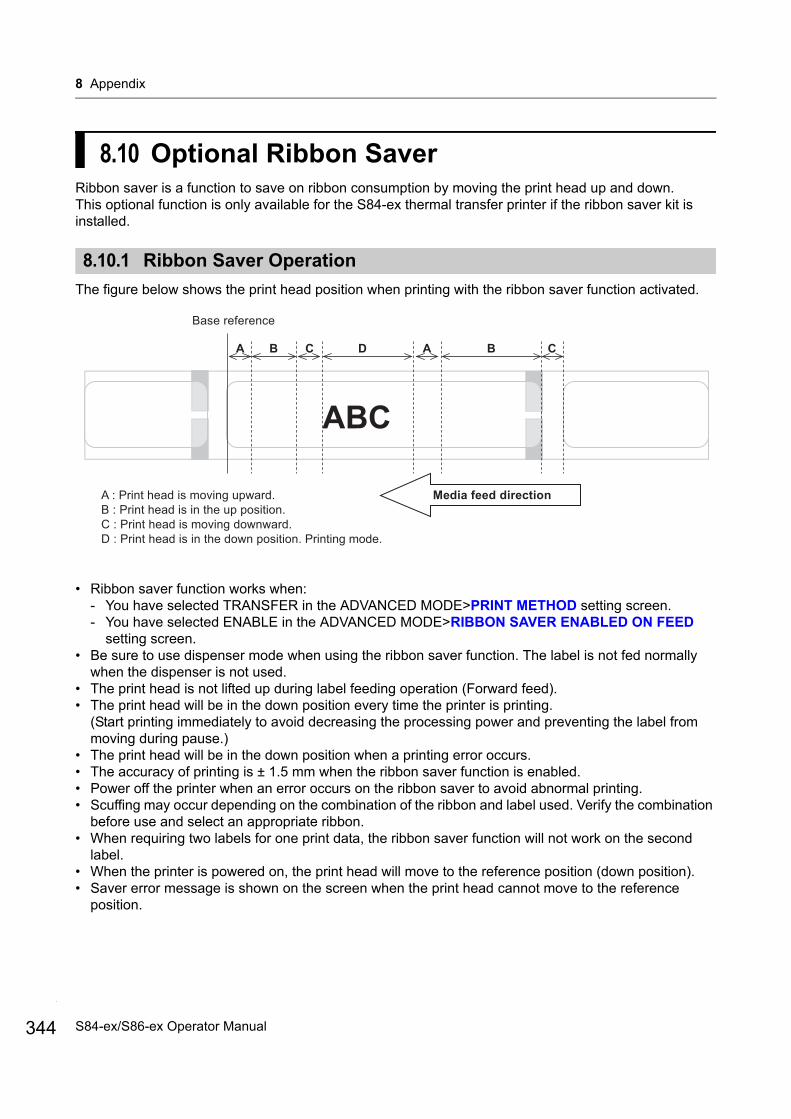
8 Appendix
344
8.10 Optional Ribbon SaverRibbon saver is a function to save on ribbon consumption by moving the print head up and down.This optional function is only available for the S84-ex thermal transfer printer if the ribbon saver kit is installed.
8.10.1 Ribbon Saver Operation
The figure below shows the print head position when printing with the ribbon saver function activated.
• Ribbon saver function works when:- You have selected TRANSFER in the ADVANCED MODE>PRINT METHOD setting screen.- You have selected ENABLE in the ADVANCED MODE>RIBBON SAVER ENABLED ON FEED
setting screen.• Be sure to use dispenser mode when using the ribbon saver function. The label is not fed normally
when the dispenser is not used.• The print head is not lifted up during label feeding operation (Forward feed).• The print head will be in the down position every time the printer is printing.
(Start printing immediately to avoid decreasing the processing power and preventing the label from moving during pause.)
• The print head will be in the down position when a printing error occurs.• The accuracy of printing is ± 1.5 mm when the ribbon saver function is enabled.• Power off the printer when an error occurs on the ribbon saver to avoid abnormal printing.• Scuffing may occur depending on the combination of the ribbon and label used. Verify the combination
before use and select an appropriate ribbon.• When requiring two labels for one print data, the ribbon saver function will not work on the second
label.• When the printer is powered on, the print head will move to the reference position (down position).• Saver error message is shown on the screen when the print head cannot move to the reference
position.
A : Print head is moving upward.B : Print head is in the up position.C : Print head is moving downward.D : Print head is in the down position. Printing mode.
CBADCBA
ABC
Base reference
Media feed direction
S84-ex/S86-ex Operator Manual
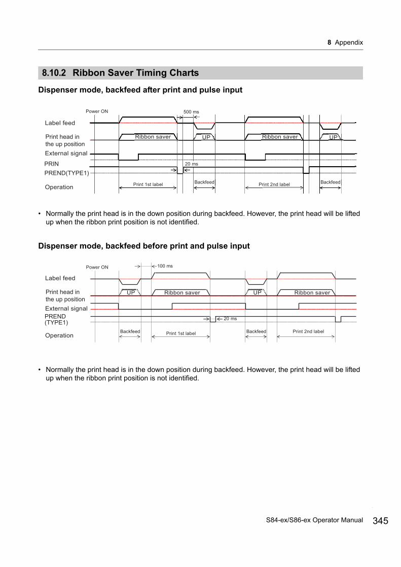
8 Appendix
8.10.2 Ribbon Saver Timing Charts
Dispenser mode, backfeed after print and pulse input
• Normally the print head is in the down position during backfeed. However, the print head will be lifted up when the ribbon print position is not identified.
Dispenser mode, backfeed before print and pulse input
• Normally the print head is in the down position during backfeed. However, the print head will be lifted up when the ribbon print position is not identified.
Power ON 500 ms
20 ms
Backfeed BackfeedPrint 1st label Print 2nd label
Print head in the up position
Label feed
External signal
PREND(TYPE1)
Operation
PRIN
Print head in the up position
100 msPower ON
Label feed
External signal
UP Ribbon saver UP Ribbon saver
20 msPREND(TYPE1)
Backfeed BackfeedPrint 1st label Print 2nd labelOperation
345S84-ex/S86-ex Operator Manual

8 Appendix
346
8.10.3 Ribbon Saver Operation and Ribbon Consumption
When a gap exists in front of the labelThe figure and table below show the minimum distance (A) from the top of the label to the print start position for each print speed required for the ribbon saver function. It also shows the consumption of the ribbon (B) when the ribbon saver is operating.
The ribbon consumption might be different from the value in the above table depending on the ribbon condition.
(unit: mm)Print speed (inches/sec)
Distance (A)Ribbon
consumption (B)2 11.0 6.5 3 12.0 7.5 4 13.0 8.8 5 14.0 9.9 6 16.0 10.5 7 16.0 11.0 8 18.0 11.5 9 19.0 12.0
10 21.0 12.5 11 22.0 13.0 12 24.0 13.5 13 26.0 14.5 14 27.0 15.0 15 29.0 16.0
16 31.0 16.5
<Label> <Ribbon>
Media feed direction
Print data 2
(A)
Print data 1
Print data 2
Print data 1
Print data 2
(B)
Print data 1
Print data 2
Print data 1
S84-ex/S86-ex Operator Manual
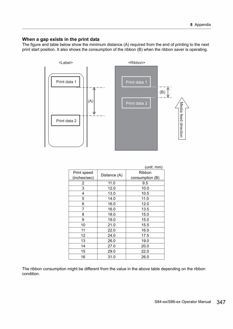
8 Appendix
When a gap exists in the print dataThe figure and table below show the minimum distance (A) required from the end of printing to the next print start position. It also shows the consumption of the ribbon (B) when the ribbon saver is operating.
The ribbon consumption might be different from the value in the above table depending on the ribbon condition.
(unit: mm)
Print speed (inches/sec)
Distance (A)Ribbon
consumption (B)2 11.0 9.5 3 12.0 10.0 4 13.0 10.5 5 14.0 11.0 6 16.0 12.0 7 16.0 13.5 8 18.0 15.0 9 19.0 15.0
10 21.0 15.5 11 22.0 16.0 12 24.0 17.5 13 26.0 19.0 14 27.0 20.0 15 29.0 22.0
16 31.0 26.0
<Label> <Ribbon>
Media feed direction
Print data 1
(A)
Print data 2
Print data 1
(B)
Print data 2
347S84-ex/S86-ex Operator Manual
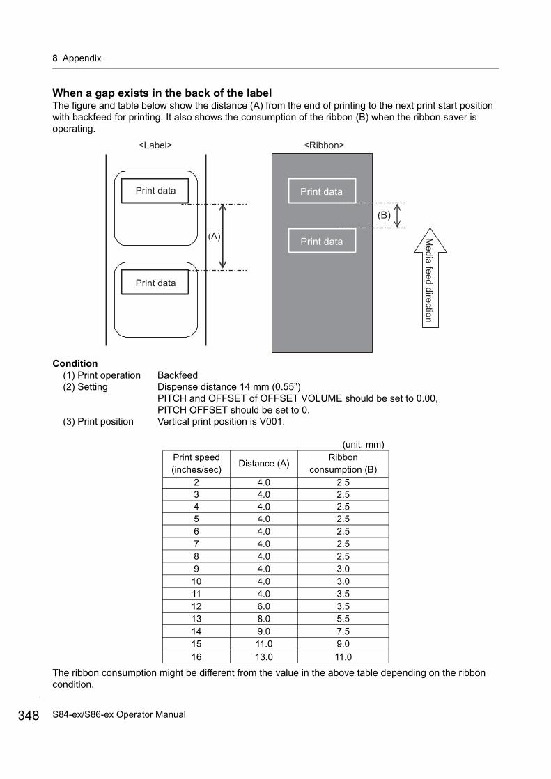
8 Appendix
348
When a gap exists in the back of the labelThe figure and table below show the distance (A) from the end of printing to the next print start position with backfeed for printing. It also shows the consumption of the ribbon (B) when the ribbon saver is operating.
Condition(1) Print operation Backfeed(2) Setting Dispense distance 14 mm (0.55”)
PITCH and OFFSET of OFFSET VOLUME should be set to 0.00, PITCH OFFSET should be set to 0.
(3) Print position Vertical print position is V001.
The ribbon consumption might be different from the value in the above table depending on the ribbon condition.
(unit: mm)Print speed (inches/sec)
Distance (A)Ribbon
consumption (B)
2 4.0 2.5 3 4.0 2.5 4 4.0 2.5 5 4.0 2.5 6 4.0 2.5 7 4.0 2.5 8 4.0 2.5 9 4.0 3.0
10 4.0 3.0 11 4.0 3.5 12 6.0 3.5 13 8.0 5.5 14 9.0 7.5 15 11.0 9.0
16 13.0 11.0
<Label> <Ribbon>
Media feed direction
Print data
(A)
Print data
Print data
(B)
Print data
S84-ex/S86-ex Operator Manual
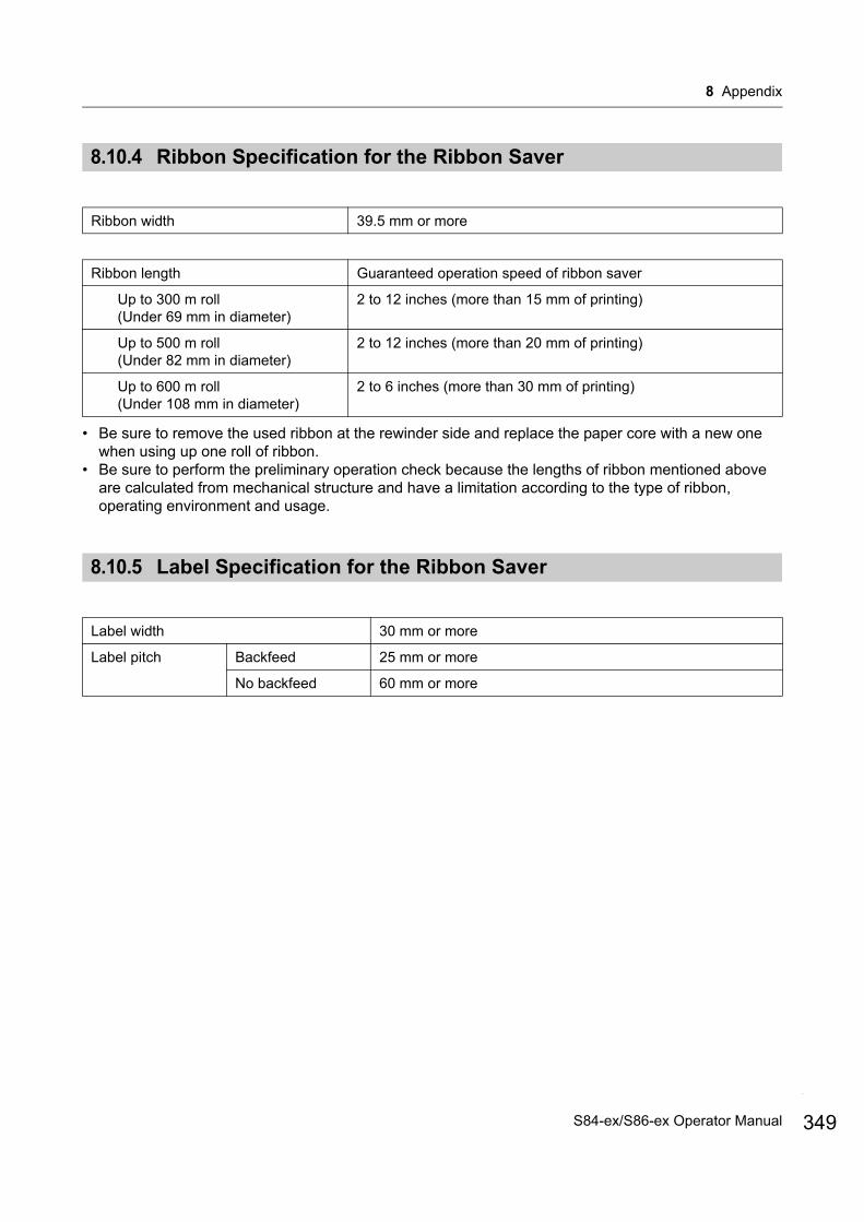
8 Appendix
8.10.4 Ribbon Specification for the Ribbon Saver
• Be sure to remove the used ribbon at the rewinder side and replace the paper core with a new one when using up one roll of ribbon.
• Be sure to perform the preliminary operation check because the lengths of ribbon mentioned above are calculated from mechanical structure and have a limitation according to the type of ribbon, operating environment and usage.
8.10.5 Label Specification for the Ribbon Saver
Ribbon width 39.5 mm or more
Ribbon length Guaranteed operation speed of ribbon saver
Up to 300 m roll (Under 69 mm in diameter)
2 to 12 inches (more than 15 mm of printing)
Up to 500 m roll (Under 82 mm in diameter)
2 to 12 inches (more than 20 mm of printing)
Up to 600 m roll (Under 108 mm in diameter)
2 to 6 inches (more than 30 mm of printing)
Label width 30 mm or more
Label pitch Backfeed 25 mm or more
No backfeed 60 mm or more
349S84-ex/S86-ex Operator Manual
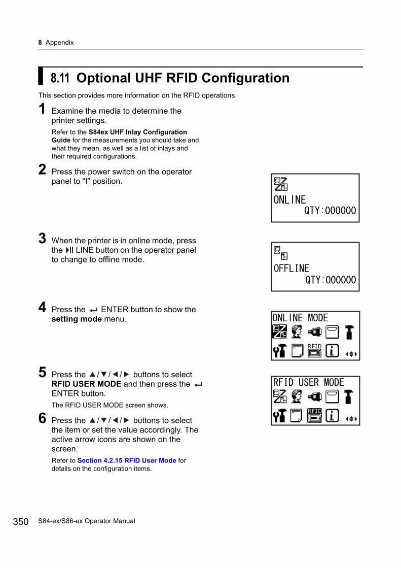
8 Appendix
350
8.11 Optional UHF RFID ConfigurationThis section provides more information on the RFID operations.
1 Examine the media to determine the printer settings.Refer to the S84ex UHF Inlay Configuration Guide for the measurements you should take and what they mean, as well as a list of inlays and their required configurations.
2 Press the power switch on the operator panel to “I” position.
3 When the printer is in online mode, press the LINE button on the operator panel to change to offline mode.
4 Press the ENTER button to show the setting mode menu.
5 Press the / / / buttons to select RFID USER MODE and then press the ENTER button.The RFID USER MODE screen shows.
6 Press the / / / buttons to select the item or set the value accordingly. The active arrow icons are shown on the screen.Refer to Section 4.2.15 RFID User Mode for details on the configuration items.
S84-ex/S86-ex Operator Manual

8 Appendix
7 Open the top cover .
CAUTIONOpen the top cover fully to prevent accidental drop of the cover.
8 Turn the head lock lever clockwise to unlock the print head.
CAUTION• The print head and its surroundings are hot after
printing. Be careful not to touch it, to avoid being burned.
• Touching the edge of the print head with your bare hand could cause injury.
9 Load the media and ribbon.Refer to Section 3.2 Loading the Ribbon and Section 3.5 Loading Media for details.
10 Confirm the operation by printing/encoding a media.Make sure that you read the data and check that it is correctly encoded.
1
2
351S84-ex/S86-ex Operator Manual
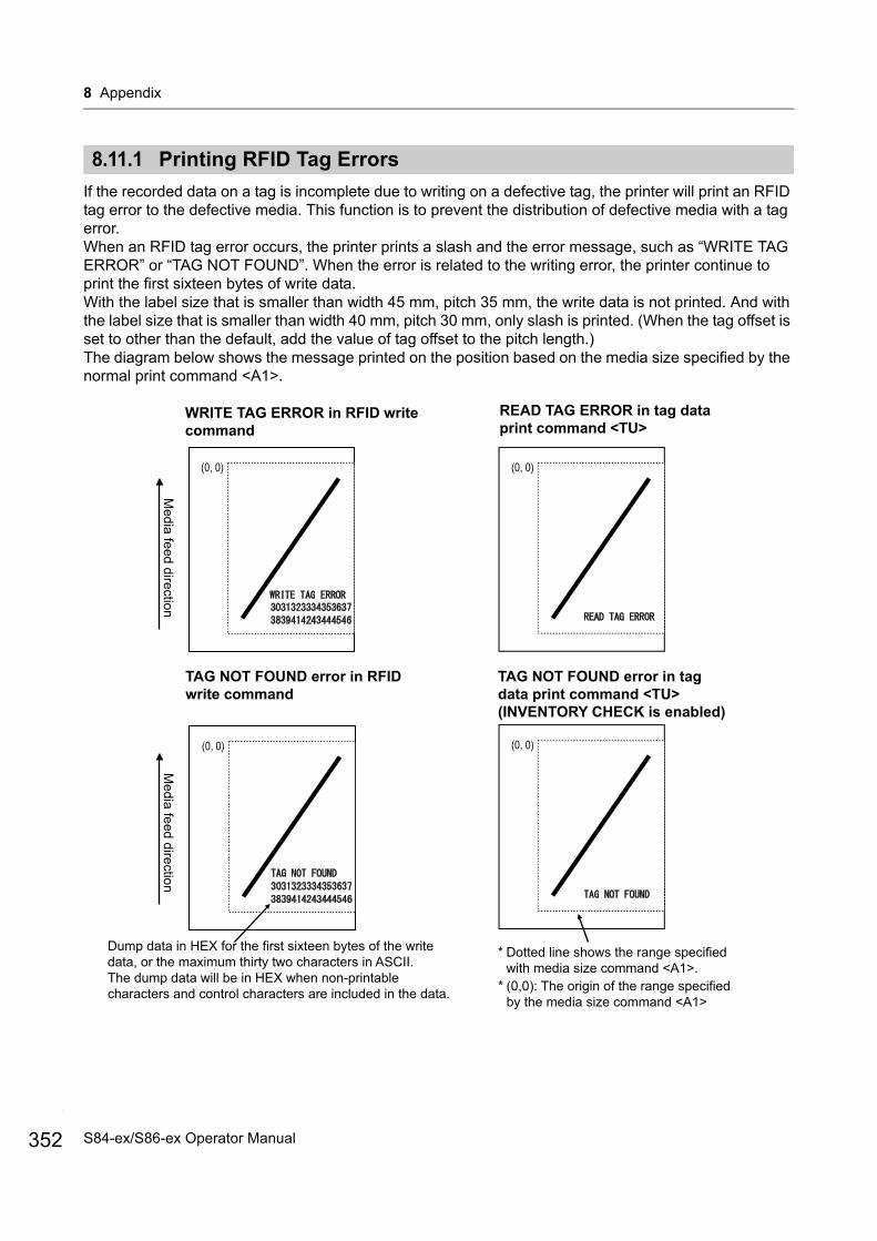
8 Appendix
352
8.11.1 Printing RFID Tag Errors
If the recorded data on a tag is incomplete due to writing on a defective tag, the printer will print an RFID tag error to the defective media. This function is to prevent the distribution of defective media with a tag error.When an RFID tag error occurs, the printer prints a slash and the error message, such as “WRITE TAG ERROR” or “TAG NOT FOUND”. When the error is related to the writing error, the printer continue to print the first sixteen bytes of write data.With the label size that is smaller than width 45 mm, pitch 35 mm, the write data is not printed. And with the label size that is smaller than width 40 mm, pitch 30 mm, only slash is printed. (When the tag offset is set to other than the default, add the value of tag offset to the pitch length.)The diagram below shows the message printed on the position based on the media size specified by the normal print command <A1>.
(0, 0)
(0, 0) (0, 0)
WRITE TAG ERROR in RFID write command
READ TAG ERROR in tag data print command <TU>
Media feed direction
TAG NOT FOUND error in RFID write command
* Dotted line shows the range specified with media size command <A1>.
Dump data in HEX for the first sixteen bytes of the write data, or the maximum thirty two characters in ASCII.The dump data will be in HEX when non-printable characters and control characters are included in the data.
Media feed direction
* (0,0): The origin of the range specified by the media size command <A1>
(0, 0)
TAG NOT FOUND error in tag data print command <TU> (INVENTORY CHECK is enabled)
S84-ex/S86-ex Operator Manual
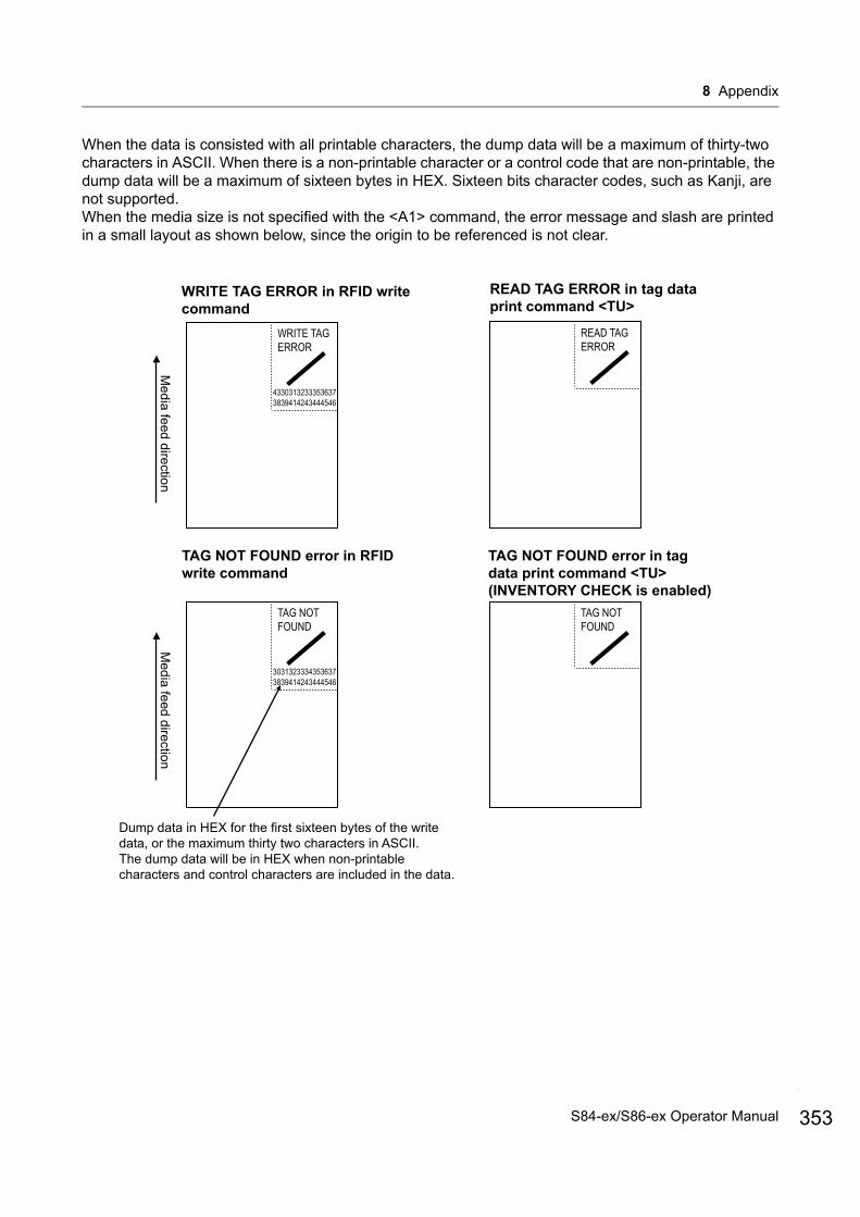
8 Appendix
When the data is consisted with all printable characters, the dump data will be a maximum of thirty-two characters in ASCII. When there is a non-printable character or a control code that are non-printable, the dump data will be a maximum of sixteen bytes in HEX. Sixteen bits character codes, such as Kanji, are not supported.When the media size is not specified with the <A1> command, the error message and slash are printed in a small layout as shown below, since the origin to be referenced is not clear.
WRITE TAG ERROR in RFID write command
READ TAG ERROR in tag data print command <TU>
Media feed direction
TAG NOT FOUND error in RFID write command
Dump data in HEX for the first sixteen bytes of the write data, or the maximum thirty two characters in ASCII.The dump data will be in HEX when non-printable characters and control characters are included in the data.
Media feed direction
TAG NOT FOUND error in tag data print command <TU> (INVENTORY CHECK is enabled)
WRITE TAG ERROR
43303132333536373839414243444546
READ TAG ERROR
TAG NOT FOUND
30313233343536373839414243444546
TAG NOT FOUND
353S84-ex/S86-ex Operator Manual
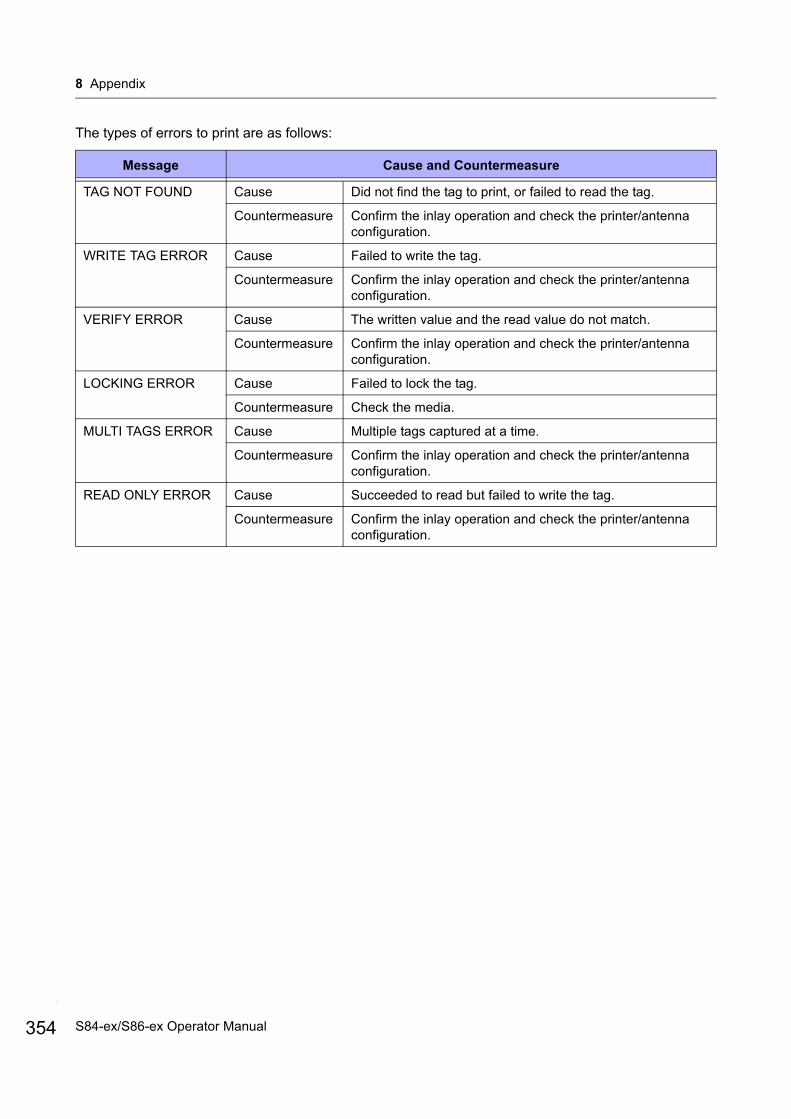
8 Appendix
354
The types of errors to print are as follows:
Message Cause and Countermeasure
TAG NOT FOUND Cause Did not find the tag to print, or failed to read the tag.
Countermeasure Confirm the inlay operation and check the printer/antenna configuration.
WRITE TAG ERROR Cause Failed to write the tag.
Countermeasure Confirm the inlay operation and check the printer/antenna configuration.
VERIFY ERROR Cause The written value and the read value do not match.
Countermeasure Confirm the inlay operation and check the printer/antenna configuration.
LOCKING ERROR Cause Failed to lock the tag.
Countermeasure Check the media.
MULTI TAGS ERROR Cause Multiple tags captured at a time.
Countermeasure Confirm the inlay operation and check the printer/antenna configuration.
READ ONLY ERROR Cause Succeeded to read but failed to write the tag.
Countermeasure Confirm the inlay operation and check the printer/antenna configuration.
S84-ex/S86-ex Operator Manual
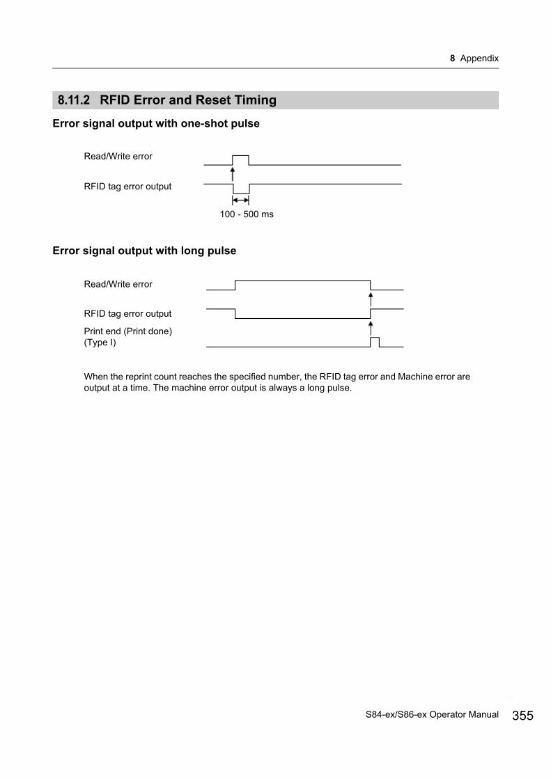
8 Appendix
8.11.2 RFID Error and Reset Timing
Error signal output with one-shot pulse
Error signal output with long pulse
Read/Write error
RFID tag error output
100 - 500 ms
Read/Write error
RFID tag error output
Print end (Print done) (Type I)
When the reprint count reaches the specified number, the RFID tag error and Machine error are output at a time. The machine error output is always a long pulse.
355S84-ex/S86-ex Operator Manual
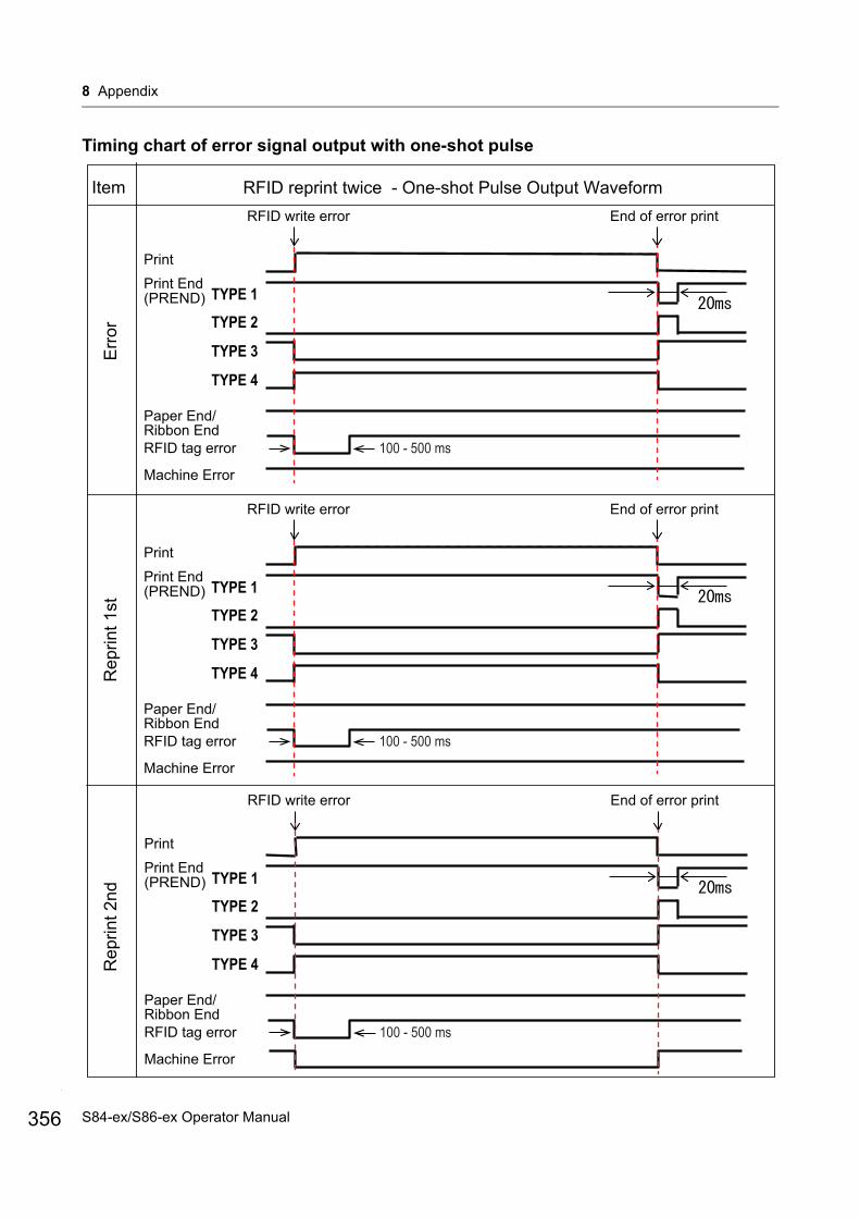
8 Appendix
356
Timing chart of error signal output with one-shot pulse
Item RFID reprint twice - One-shot Pulse Output WaveformEnd of error print
(PREND)Print EndPrint
Rep
rint 1
stR
eprin
t 2nd
Err
or
Paper End/Ribbon EndRFID tag error
Machine Error
TYPE 1
TYPE 2
TYPE 3
TYPE 4
RFID write error
100 - 500 ms
End of error print
(PREND)Print EndPrint
Paper End/Ribbon EndRFID tag error
Machine Error
TYPE 1
TYPE 2
TYPE 3
TYPE 4
RFID write error
100 - 500 ms
End of error print
(PREND)Print EndPrint
Paper End/Ribbon EndRFID tag error
Machine Error
TYPE 1
TYPE 2
TYPE 3
TYPE 4
RFID write error
100 - 500 ms
S84-ex/S86-ex Operator Manual
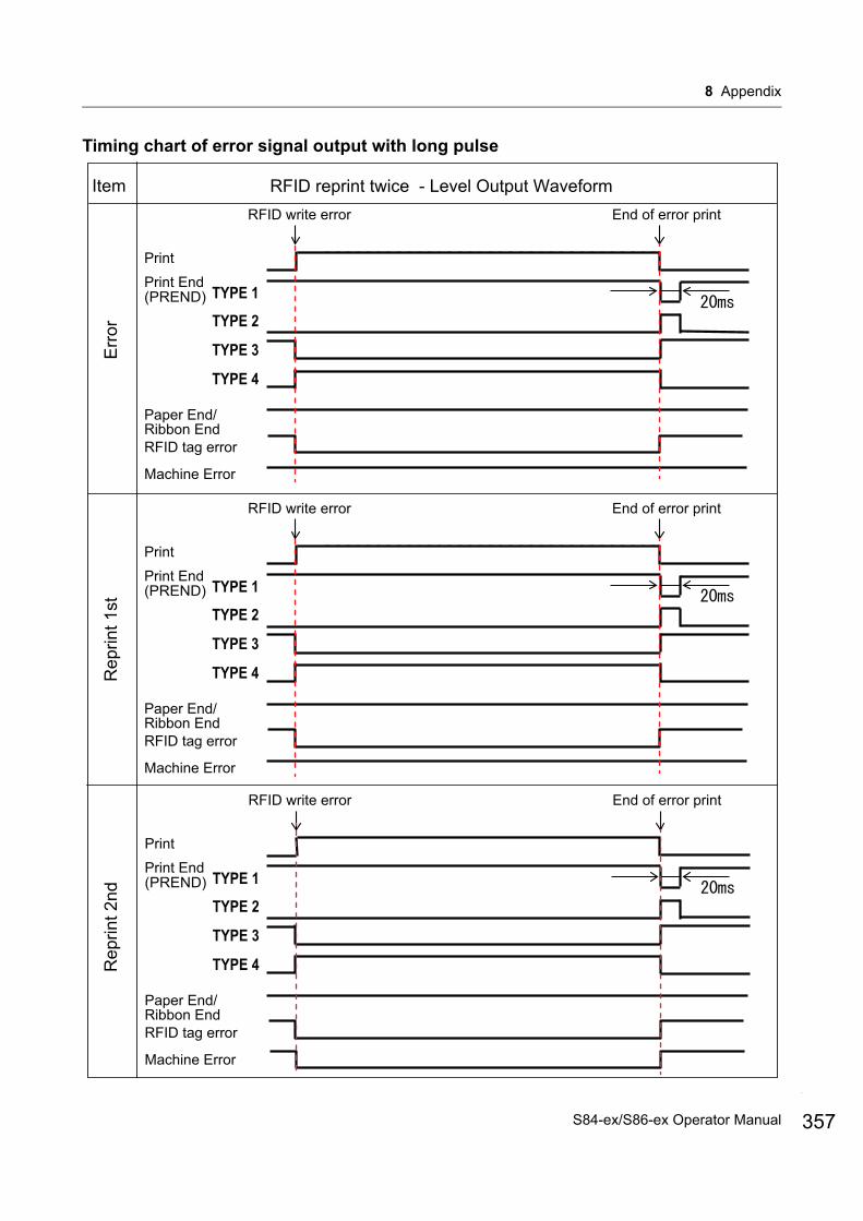
8 Appendix
Timing chart of error signal output with long pulse
Item RFID reprint twice - Level Output WaveformEnd of error print
(PREND)Print EndPrint
Rep
rint 1
stR
eprin
t 2nd
Err
or
Paper End/Ribbon EndRFID tag error
Machine Error
TYPE 1
TYPE 2
TYPE 3
TYPE 4
RFID write error
End of error print
(PREND)Print EndPrint
Paper End/Ribbon EndRFID tag error
Machine Error
TYPE 1
TYPE 2
TYPE 3
TYPE 4
RFID write error
End of error print
(PREND)Print EndPrint
Paper End/Ribbon EndRFID tag error
Machine Error
TYPE 1
TYPE 2
TYPE 3
TYPE 4
RFID write error
357S84-ex/S86-ex Operator Manual

8 Appendix
358
8.11.3 External (EXT) Signal Interfaces when RFID Module is Enabled
Standard specification is applied when the RFID module is set to DISABLE. Functions shown by shading are applied when the RFID module is set to ENABLE.
Pin No. Signal NameInput/Output(25 pins) (14 pins)
Standard SpecificationRFID Module Disabled
RFID Module Enabled
1 14 Frame Ground Frame Ground -
2 - +5 V +5 V -
3 - - - -
4 4 Machine Error Machine Error/RFID Error Output
5 6 Print end signal (PREND) Print end signal (PREND) Output
6 9 Online Online Output
7 - Label Near End Label Near End Input
8 7 Reprint signal (PRIN2) Reprint signal (PRIN2) Input
9 - - - -
10 - - - -
11 - OUT_COM OUT_COM -
12 13 +5 V +5 V -
13 12 +24 V +24 V -
14 2 GND GND -
15 2 OUT_COM OUT_COM -
16 3 Ribbon End RFID Tag Error Output
17 1 Paper End Paper End + Ribbon End Output
18 10 Ribbon Near End Ribbon Near End Output
19 - - - -
20 5 Print start signal (PRIN) Print start signal (PRIN) Input
21 11 Label Feed Label Feed Input
22 - - - -
23 - - - -
24 13 IN_COM IN_COM Input
25 - GND GND -
S84-ex/S86-ex Operator Manual
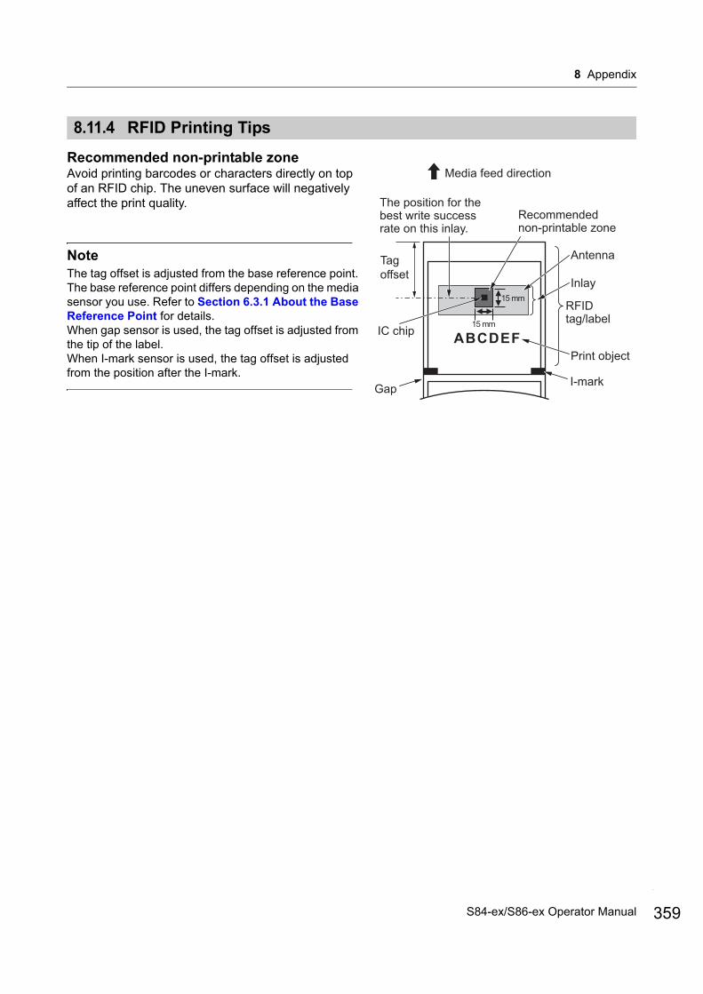
8 Appendix
8.11.4 RFID Printing Tips
Recommended non-printable zoneAvoid printing barcodes or characters directly on top of an RFID chip. The uneven surface will negatively affect the print quality.
NoteThe tag offset is adjusted from the base reference point. The base reference point differs depending on the media sensor you use. Refer to Section 6.3.1 About the Base Reference Point for details.When gap sensor is used, the tag offset is adjusted from the tip of the label.When I-mark sensor is used, the tag offset is adjusted from the position after the I-mark.
15 mm
15 mm
Media feed direction
IC chip
I-mark
Print object
Inlay
Gap
Antenna
RFID tag/label
Recommended non-printable zone
Tag offset
The position for the best write success rate on this inlay.
359S84-ex/S86-ex Operator Manual
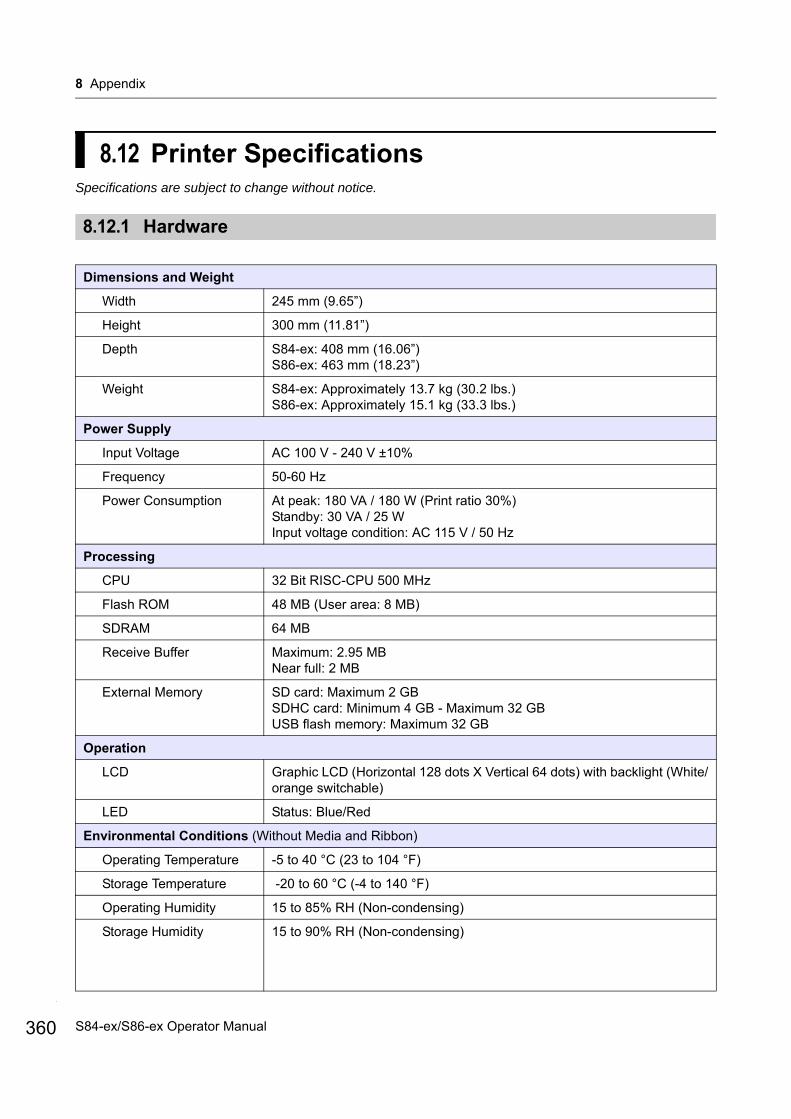
8 Appendix
360
8.12 Printer SpecificationsSpecifications are subject to change without notice.
8.12.1 Hardware
Dimensions and Weight
Width 245 mm (9.65”)
Height 300 mm (11.81”)
Depth S84-ex: 408 mm (16.06”)S86-ex: 463 mm (18.23”)
Weight S84-ex: Approximately 13.7 kg (30.2 lbs.)S86-ex: Approximately 15.1 kg (33.3 lbs.)
Power Supply
Input Voltage AC 100 V - 240 V ±10%
Frequency 50-60 Hz
Power Consumption At peak: 180 VA / 180 W (Print ratio 30%)Standby: 30 VA / 25 WInput voltage condition: AC 115 V / 50 Hz
Processing
CPU 32 Bit RISC-CPU 500 MHz
Flash ROM 48 MB (User area: 8 MB)
SDRAM 64 MB
Receive Buffer Maximum: 2.95 MBNear full: 2 MB
External Memory SD card: Maximum 2 GBSDHC card: Minimum 4 GB - Maximum 32 GBUSB flash memory: Maximum 32 GB
Operation
LCD Graphic LCD (Horizontal 128 dots X Vertical 64 dots) with backlight (White/orange switchable)
LED Status: Blue/Red
Environmental Conditions (Without Media and Ribbon)
Operating Temperature -5 to 40 °C (23 to 104 °F)
Storage Temperature -20 to 60 °C (-4 to 140 °F)
Operating Humidity 15 to 85% RH (Non-condensing)
Storage Humidity 15 to 90% RH (Non-condensing)
S84-ex/S86-ex Operator Manual
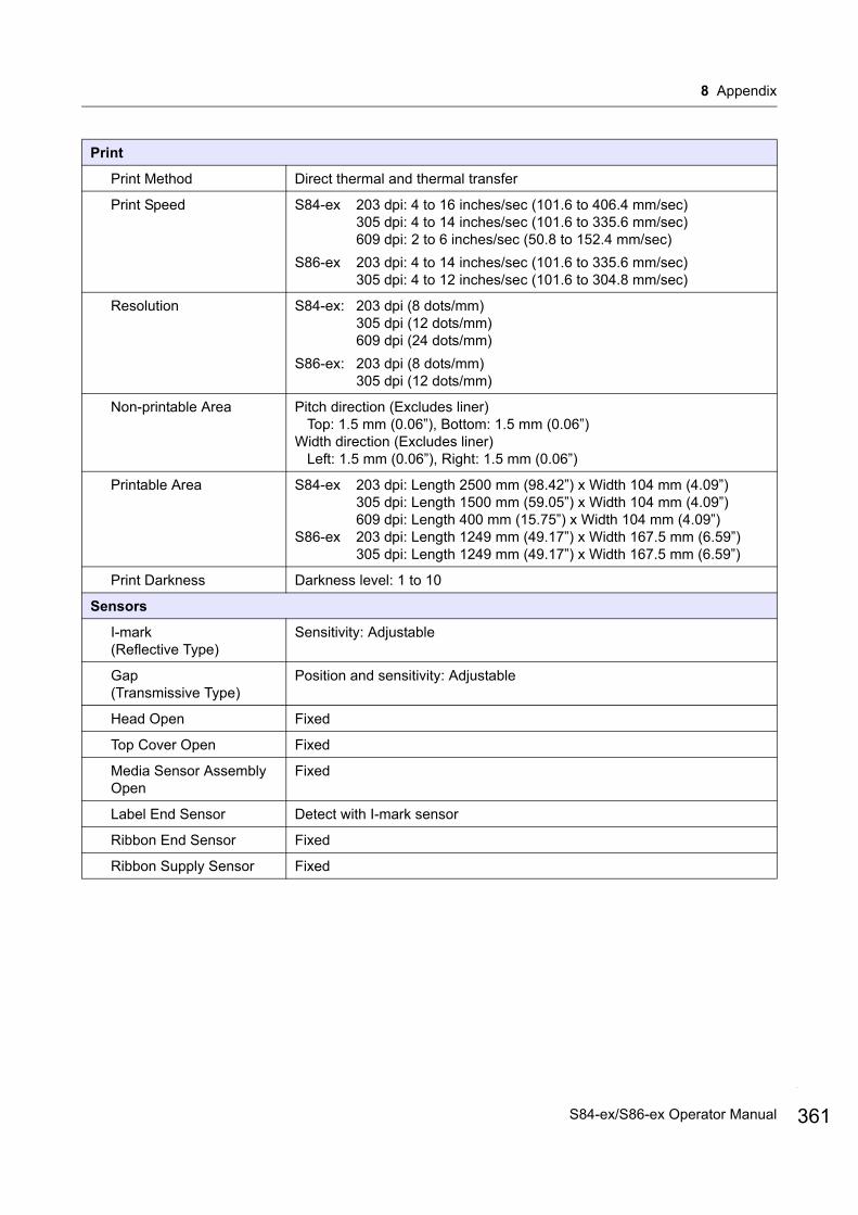
8 Appendix
Print Method Direct thermal and thermal transfer
Print Speed S84-ex 203 dpi: 4 to 16 inches/sec (101.6 to 406.4 mm/sec)305 dpi: 4 to 14 inches/sec (101.6 to 335.6 mm/sec)609 dpi: 2 to 6 inches/sec (50.8 to 152.4 mm/sec)
S86-ex 203 dpi: 4 to 14 inches/sec (101.6 to 335.6 mm/sec)305 dpi: 4 to 12 inches/sec (101.6 to 304.8 mm/sec)
Resolution S84-ex: 203 dpi (8 dots/mm)305 dpi (12 dots/mm)609 dpi (24 dots/mm)
S86-ex: 203 dpi (8 dots/mm)305 dpi (12 dots/mm)
Non-printable Area Pitch direction (Excludes liner)Top: 1.5 mm (0.06”), Bottom: 1.5 mm (0.06”)
Width direction (Excludes liner)Left: 1.5 mm (0.06”), Right: 1.5 mm (0.06”)
Printable Area S84-ex 203 dpi: Length 2500 mm (98.42”) x Width 104 mm (4.09”)305 dpi: Length 1500 mm (59.05”) x Width 104 mm (4.09”)609 dpi: Length 400 mm (15.75”) x Width 104 mm (4.09”)
S86-ex 203 dpi: Length 1249 mm (49.17”) x Width 167.5 mm (6.59”)305 dpi: Length 1249 mm (49.17”) x Width 167.5 mm (6.59”)
Print Darkness Darkness level: 1 to 10
Sensors
I-mark(Reflective Type)
Sensitivity: Adjustable
Gap(Transmissive Type)
Position and sensitivity: Adjustable
Head Open Fixed
Top Cover Open Fixed
Media Sensor Assembly Open
Fixed
Label End Sensor Detect with I-mark sensor
Ribbon End Sensor Fixed
Ribbon Supply Sensor Fixed
361S84-ex/S86-ex Operator Manual

8 Appendix
362
8.12.2 Ribbon and Media
Ribbon (Use genuine ribbon made by SATO.)
Size S84-ex Width: 25 mm to 128 mm (0.98” to 5.04”)Length:
450 m (1476.4 ft.) when width is less than 39.5 mm (1.55”)600 m (1968.5 ft.) when width is equal or more than 39.5 mm (1.55”)
S86-ex Width: 59 mm to 177 mm (2.32” to 6.97”)Length: 600 m (1968.5 ft.) when width is equal or more than 59 mm (2.32”)
Wind Direction Face-out/Face-in
Roll Diameter 108 mm (4.25”)
Core Diameter 25.6 mm (1.01”)
Media (Use genuine media made by SATO.)
Type Media roll (Face-in wound/face-out wound), fan-fold media
Size
Continuous Mode
Pitch
(With Liner)
* There is a restriction with the speed for the small pitch label.
S84-ex 203 dpi: 6 to 2500 mm (0.24” to 98.42”)305 dpi: 6 to 1500 mm (0.24” to 59.06”)609 dpi: 6 to 400 mm (0.24” to 15.75”)
S86-ex 203 dpi: 6 to 1249 mm (0.24” to 49.17”)305 dpi: 6 to 1249 mm (0.24” to 49.17”)
S84-ex 203 dpi: 9 to 2503 mm (0.35” to 98.54”)305 dpi: 9 to 1503 mm (0.35” to 59.17”)609 dpi: 9 to 403 mm (0.35” to 15.87”)
S86-ex 203 dpi: 9 to 1252 mm (0.35” to 49.29”)305 dpi: 9 to 1252 mm (0.35” to 49.29”)
Width
(With Liner)
S84-ex 10 to 128 mm (0.39” to 5.04”)S86-ex 51 to 177 mm (2.01” to 6.97”)
S84-ex 13 to 131 mm (0.51” to 5.16”)S86-ex 54 to 180 mm (2.13” to 7.09”)
S84-ex/S86-ex Operator Manual
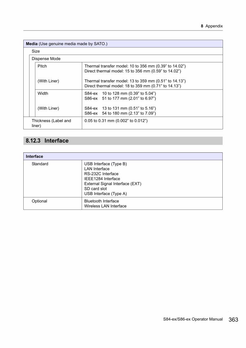
8 Appendix
8.12.3 Interface
Media (Use genuine media made by SATO.)
Size
Dispense Mode
Pitch
(With Liner)
Thermal transfer model: 10 to 356 mm (0.39” to 14.02”)Direct thermal model: 15 to 356 mm (0.59” to 14.02”)
Thermal transfer model: 13 to 359 mm (0.51” to 14.13”)Direct thermal model: 18 to 359 mm (0.71” to 14.13”)
Width
(With Liner)
S84-ex 10 to 128 mm (0.39” to 5.04”)S86-ex 51 to 177 mm (2.01” to 6.97”)
S84-ex 13 to 131 mm (0.51” to 5.16”)S86-ex 54 to 180 mm (2.13” to 7.09”)
Thickness (Label and liner)
0.05 to 0.31 mm (0.002” to 0.012”)
Interface
Standard USB Interface (Type B)LAN InterfaceRS-232C InterfaceIEEE1284 InterfaceExternal Signal Interface (EXT)SD card slotUSB Interface (Type A)
Optional Bluetooth InterfaceWireless LAN Interface
363S84-ex/S86-ex Operator Manual

8 Appendix
364
8.12.4 Built-in Functions
8.12.5 Printer Languages
Functions
Built-in Functions Status returnGraphicSequential numberForm overlayExternal font registrationCharacter modificationBlack/white inversionRuled lineDump list (Hex dump mode)Format registrationOutline fontOutline modificationZero slash switchingUnicode (UTF-8/UTF-16) switchingSimple standaloneWork shift setting modeXML printWEB browser printer setting (If wireless LAN is installed)
Self-diagnosis Functions Broken head element checkHead open detectionPaper end detectionRibbon end detectionRibbon near-end detectionTest printKanji data checkCover open detectionCalendar check settingSensor cover open detectionLabel near end signal receive and input from the applicator, and report output of label near end status through EXT.
Adjustment Functions Print DarknessPrint PositionMedia Stop PositionBuzzer VolumeLCD Brightness
Protective Functions Head overheating protection functionPower supply temperature monitor function
Printer Languages
SBPLSZPLSDPL
S84-ex/S86-ex Operator Manual

8 Appendix
8.12.6 Fonts/Symbols/Barcodes
Fonts
Bitmap Fonts
U 9 dots H x 5 dots W
S 15 dots H x 8 dots W
M 20 dots H x 13 dots W
WB 30 dots H x 18 dots W
WL 52 dots H x 28 dots W
XU 9 dots H x 5 dots W
XS 17 dots H x 17 dots W
XM 24 dots H x 24 dots W
XB 48 dots H x 48 dots W
XL 48 dots H x 48 dots W
OCR-A S84-ex/S86-ex 203 dpi: 22 dots H x 15 dots WS84-ex/S86-ex 305 dpi: 33 dots H x 22 dots WS84-ex 609 dpi: 66 dots H x 44 dots W
OCR-B S84-ex/S86-ex 203 dpi: 24 dots H x 20 dots WS84-ex/S86-ex 305 dpi: 36 dots H x 30 dots WS84-ex 609 dpi: 72 dots H x 60 dots W
Simplified Chinese Characters (GB18030)
Mincho 16 dots H x 16 dots W24 dots H x 24 dots W
Gothic 24 dots H x 24 dots W
Traditional Chinese Characters (BIG5)
Mincho 24 dots H x 24 dots W
Korea Fonts (KSX1001) Mincho 16 dots H x 16 dots W24 dots H x 24 dots W
Scalable Fonts
Rasterized Font CG TimesCG Triumvirate*Support Codepage 858, Bold/Italic
SATO GammaSATO Vica* Support WGL4
Thai (CP874)Arabic
Outline Fonts Alphanumeric, Symbols
Extended Fonts Font downloaded data (Support 1-byte, 2-byte characters)
365S84-ex/S86-ex Operator Manual
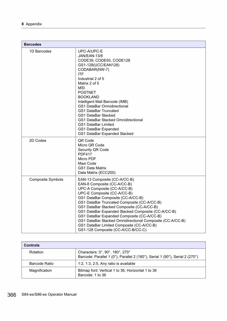
8 Appendix
366
Barcodes
1D Barcodes UPC-A/UPC-EJAN/EAN-13/8CODE39, CODE93, CODE128GS1-128(UCC/EAN128)CODABAR(NW-7)ITFIndustrial 2 of 5Matrix 2 of 5MSIPOSTNETBOOKLANDIntelligent Mail Barcode (IMB)GS1 DataBar OmnidirectionalGS1 DataBar TruncatedGS1 DataBar StackedGS1 DataBar Stacked OmnidirectionalGS1 DataBar LimitedGS1 DataBar ExpandedGS1 DataBar Expanded Stacked
2D Codes QR CodeMicro QR CodeSecurity QR CodePDF417Micro PDFMaxi CodeGS1 Data MatrixData Matrix (ECC200)
Composite Symbols EAN-13 Composite (CC-A/CC-B)EAN-8 Composite (CC-A/CC-B)UPC-A Composite (CC-A/CC-B)UPC-E Composite (CC-A/CC-B)GS1 DataBar Composite (CC-A/CC-B)GS1 DataBar Truncated Composite (CC-A/CC-B)GS1 DataBar Stacked Composite (CC-A/CC-B)GS1 DataBar Expanded Stacked Composite (CC-A/CC-B)GS1 DataBar Expanded Composite (CC-A/CC-B)GS1 DataBar Stacked Omnidirectional Composite (CC-A/CC-B)GS1 DataBar Limited Composite (CC-A/CC-B)GS1-128 Composite (CC-A/CC-B/CC-C)
Controls
Rotation Characters: 0°, 90°, 180°, 270°Barcode: Parallel 1 (0°), Parallel 2 (180°), Serial 1 (90°), Serial 2 (270°)
Barcode Ratio 1:2, 1:3, 2:5, Any ratio is available
Magnification Bitmap font: Vertical 1 to 36, Horizontal 1 to 36Barcode: 1 to 36
S84-ex/S86-ex Operator Manual

8 Appendix
8.12.7 Options
8.12.8 Accessories
8.12.9 Standards
Options
1) Wireless LAN interface kit2) Bluetooth kit3) Linerless (Only for S84-ex)4) RFID (UHF) kit (Only for S84-ex)5) Ribbon saver (Only for S84-ex)
Accessories
1) AC power cord2) Documentations (Quick Guide, Global Warranty Program leaflet, etc.)3) 14-pin conversion cable4) Ribbon core
Standards
Safety Standards CB IEC 60950-1, UL60950-1, CSA C22.2, EN60950-1, CCC, KC, BIS, RCM, EAC
EMC Standards FCC PART15B Class A, ICES-003 Class A,EN55024, EN55032, CCC,KC, BIS, RCM, EAC
Environmental StandardRoHS
RoHS directive (six hazardous) restricts the use of six hazardous materials listed below.
Hexavalent chromium . . . . . . . . . . . . . . . . . . . . .Max. 0.1%Lead and lead compounds . . . . . . . . . . . . . . . . .Max. 0.1%Mercury and mercury compounds . . . . . . . . . . .Max. 0.1%Cadmium and cadmium compounds . . . . . . . . .Max. 0.01%Polybrominated biphenyls (PBB) . . . . . . . . . . . .Max. 0.1%Polybrominated diphenyl ethers (PBDE) . . . . . .Max. 0.1%
Wireless LAN (2.45 GHz) KC, R&TTE
367S84-ex/S86-ex Operator Manual
8 Appendix
368
8.13 Interface SpecificationsFor data communication with the host, this printer supports the following interfaces:You can set the various interface settings of the printer through the Interface Mode menu.
• USB (USB type B)• LAN Ethernet• RS-232C (DB 9 pins, female)• IEEE1284 (Amphenol 36 pins)• External signal (EXT) (DB 25 pins, female)• Optional Bluetooth• Optional Wireless LAN
CAUTIONDo not connect or disconnect the interface cables (or use a switch box) with power supplied to either the printer or host. This may cause damage to the interface circuitry in the printer or host and is not covered by warranty.
Note• Bluetooth and wireless LAN are optional interfaces.• You cannot use the wireless LAN interface and USB interface at a time.
S84-ex/S86-ex Operator Manual
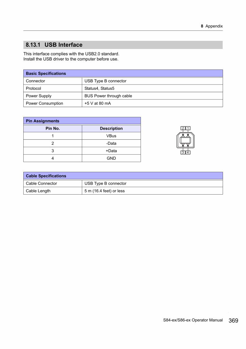
8 Appendix
8.13.1 USB Interface
This interface complies with the USB2.0 standard.Install the USB driver to the computer before use.
Basic Specifications
Connector USB Type B connector
Protocol Status4, Status5
Power Supply BUS Power through cable
Power Consumption +5 V at 80 mA
Pin Assignments
Pin No. Description
1 VBus
2 -Data
3 +Data
4 GND
Cable Specifications
Cable Connector USB Type B connector
Cable Length 5 m (16.4 feet) or less
12
43
369S84-ex/S86-ex Operator Manual
8 Appendix
370
8.13.2 LAN Ethernet Interface
Basic Specifications (When IPv4 is selected)
Connector RJ-45 Receptacle
Power Supply Powered from the printer
Protocol Status3Status4 (Cyclic response mode)Status4 (ENQ response mode)Status5
IP Address 0.0.0.0 - 255.255.255.255Initial: 192.168.1.1
Subnet Mask 0.0.0.0 - 255.255.255.255Initial: 255.255.255.0
Gateway Address 0.0.0.0 - 255.255.255.255Initial: 0.0.0.0
Basic Specifications (When IPv6 is selected)
Connector RJ-45 Receptacle
Power Supply Powered from the printer
Protocol Status3Status4 (Cyclic response mode)Status4 (ENQ response mode)Status5
IP Address 0000:0000:0000:0000:0000:0000:0000:0000 - FFFF:FFFF:FFFF:FFFF:FFFF:FFFF:FFFF:FFFFInitial: 0000:0000:0000:0000:0000:0000:0000:0000
Prefix 0 -128Initial: 64
Default Router 0000:0000:0000:0000:0000:0000:0000:0000 - FFFF:FFFF:FFFF:FFFF:FFFF:FFFF:FFFF:FFFFInitial: 0000:0000:0000:0000:0000:0000:0000:0000
S84-ex/S86-ex Operator Manual
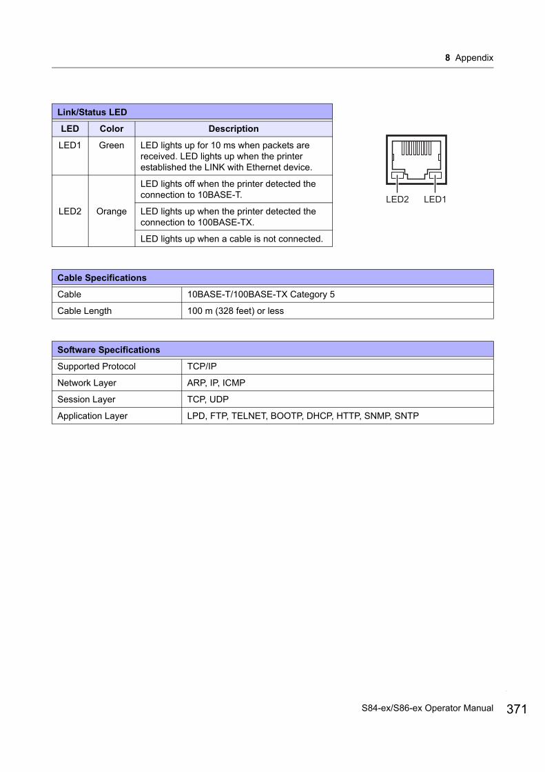
8 Appendix
Link/Status LED
LED Color Description
LED1 Green LED lights up for 10 ms when packets are received. LED lights up when the printer established the LINK with Ethernet device.
LED2 Orange
LED lights off when the printer detected the connection to 10BASE-T.
LED lights up when the printer detected the connection to 100BASE-TX.
LED lights up when a cable is not connected.
Cable Specifications
Cable 10BASE-T/100BASE-TX Category 5
Cable Length 100 m (328 feet) or less
Software Specifications
Supported Protocol TCP/IP
Network Layer ARP, IP, ICMP
Session Layer TCP, UDP
Application Layer LPD, FTP, TELNET, BOOTP, DHCP, HTTP, SNMP, SNTP
LED1LED2
371S84-ex/S86-ex Operator Manual
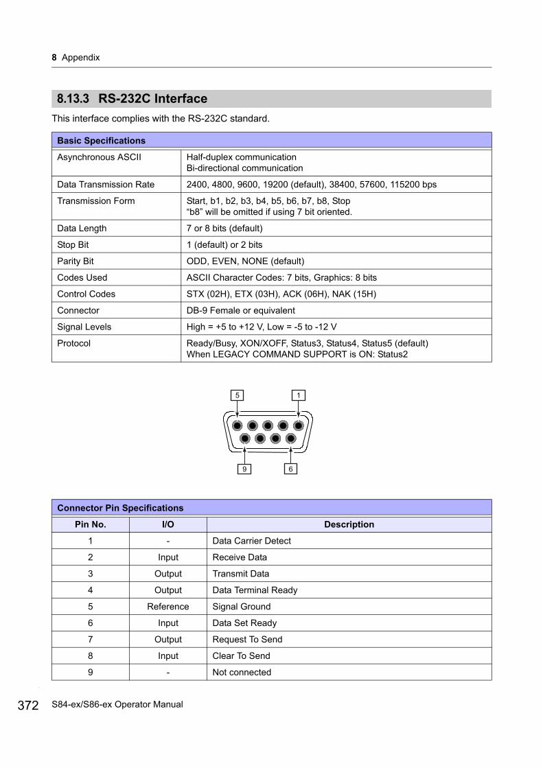
8 Appendix
372
8.13.3 RS-232C Interface
This interface complies with the RS-232C standard.
Basic Specifications
Asynchronous ASCII Half-duplex communicationBi-directional communication
Data Transmission Rate 2400, 4800, 9600, 19200 (default), 38400, 57600, 115200 bps
Transmission Form Start, b1, b2, b3, b4, b5, b6, b7, b8, Stop“b8” will be omitted if using 7 bit oriented.
Data Length 7 or 8 bits (default)
Stop Bit 1 (default) or 2 bits
Parity Bit ODD, EVEN, NONE (default)
Codes Used ASCII Character Codes: 7 bits, Graphics: 8 bits
Control Codes STX (02H), ETX (03H), ACK (06H), NAK (15H)
Connector DB-9 Female or equivalent
Signal Levels High = +5 to +12 V, Low = -5 to -12 V
Protocol Ready/Busy, XON/XOFF, Status3, Status4, Status5 (default)When LEGACY COMMAND SUPPORT is ON: Status2
Connector Pin Specifications
Pin No. I/O Description
1 - Data Carrier Detect
2 Input Receive Data
3 Output Transmit Data
4 Output Data Terminal Ready
5 Reference Signal Ground
6 Input Data Set Ready
7 Output Request To Send
8 Input Clear To Send
9 - Not connected
15
69
S84-ex/S86-ex Operator Manual
8 Appendix
Note• When using the READY/BUSY control, make sure that the printer is in power on mode before you send the
data from the host.• With communication protocols such as XON/XOFF, STATUS3, STATUS4 or STATUS5, a receive buffer full
error will occur when the received data is more than the receive buffer size (2.95 MB). Send data that is less than 2.95 MB while monitoring the status of the printer.
• A parity error will be detected if this error occurs after the reception of ESC+A.
Cable Specifications
Cable Connector DB-9 Male or equivalent
Cable Length 5 m (16.4 feet) or less
373S84-ex/S86-ex Operator Manual
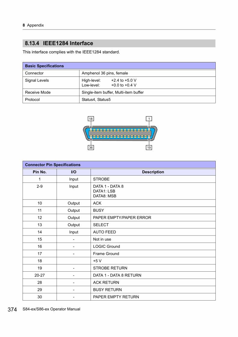
8 Appendix
374
8.13.4 IEEE1284 Interface
This interface complies with the IEEE1284 standard.
Basic Specifications
Connector Amphenol 36 pins, female
Signal Levels High-level: +2.4 to +5.0 VLow-level: +0.0 to +0.4 V
Receive Mode Single-item buffer, Multi-item buffer
Protocol Status4, Status5
Connector Pin Specifications
Pin No. I/O Description
1 Input STROBE
2-9 Input DATA 1 - DATA 8DATA1: LSBDATA8: MSB
10 Output ACK
11 Output BUSY
12 Output PAPER EMPTY/PAPER ERROR
13 Output SELECT
14 Input AUTO FEED
15 - Not in use
16 - LOGIC Ground
17 - Frame Ground
18 +5 V
19 - STROBE RETURN
20-27 - DATA 1 - DATA 8 RETURN
28 - ACK RETURN
29 - BUSY RETURN
30 - PAPER EMPTY RETURN
118
1936
S84-ex/S86-ex Operator Manual
8 Appendix
Pin No. I/O Description
31 Input INITIALIZE
32 Output FAULT
33-35 - Not in use
36 Input SELECT INPUT
Cable Specifications
Cable Connector Amphenol 36 pins, male
Cable Length 1.5 m (5 feet) or less
Connector Pin Specifications
375S84-ex/S86-ex Operator Manual
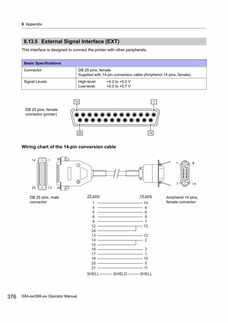
8 Appendix
376
8.13.5 External Signal Interface (EXT)
This interface is designed to connect the printer with other peripherals.
Wiring chart of the 14-pin conversion cable
Basic Specifications
Connector DB 25 pins, femaleSupplied with 14-pin conversion cable (Amphenol 14 pins, female)
Signal Levels High-level: +4.2 to +5.0 VLow-level: +0.0 to +0.7 V
113
1425
DB 25 pins, female connector (printer)
25 pins 14 pins
1 144 45 66 98 7
12 1324
121314 21516 317 118 1020 521 11
SHELL SHELLSHIELD
Amphenol 14 pins, female connector
DB 25 pins, male connector
S84-ex/S86-ex Operator Manual

8 Appendix
Connector Pin Specifications
Pin No.I/O Description
(25 pins) (14 pins)
1 14 - Frame Ground
2 - - Vcc +5 V (Maximum current 500 mA) 500 mA in total for Pin No. 2 and 12.
3 - Output Print Start Position Signal (HOME POSITION)When backfeed motion is set to CONTROLED, outputs a low signal when backfeed is done.
4 4 Output Machine Error:Outputs a low signal when an error such as the head open error is detected.
5 6 Output Print end signal (PREND):Outputs a signal when the media print is completed.
6 9 Output Online*3:Outputs a low signal when the printer is in offline mode.
7 - Input*2 Label Near End:Printer received a label near end signal when a low signal is detected.
8 7 Input*2 Reprint signal (PRIN2):Prints the previously printed content again when a low signal is detected.
9 - Input*2 Backfeed Order (DISPENSE IN)When backfeed motion is set to CONTROLED, perform a backfeed when a low signal is detected.
10 - - -
11 - - OUT_COM: Ground of peripherals
12 13 - Vcc +5 V (Maximum current 500 mA) 500 mA in total for Pin No. 2 and 12.
13 12 - VCC +24V (Maximum current 2 A)
14 2 - GND: Reference Signal Ground
15 2 - OUT_COM: Ground of peripherals
16 3 Output Ribbon End:Outputs a low signal when the ribbon end is detected.
17 1 Output Paper End:Outputs a low signal when the paper end is detected.
18 10 Output Ribbon Near End:Outputs a high signal when the ribbon near end is detected.
19 - - -
20 5 Input*2 Print start signal (PRIN):Prints one media when a low signal is detected.
21 11 Input*2 Label Feed:Feeds one media when a low signal is detected.
377S84-ex/S86-ex Operator Manual

8 Appendix
378
Note• You can set the external signal type (TYPE1 to TYPE4) for PREND output signal of pin No. 5. Refer to the
EXTERNAL SIGNAL screen of the Advanced Mode menu for details.• You can set the pin number for input and output through the INPUT SIGNAL/OUTPUT SIGNAL screen of
the Advanced Mode menu.
*1When using the 14-pin conversion cable, do not connect the power pin to [IN_COM] pin. The [IN COM] pin is connected to 5 V in cable.
*2These input signal terminals can be connected to the open collector input devices.*3This is online output signal when MODE2 is selected in the EXT 9PIN SELECT screen of the service mode.
The signal outputs the status of the remaining print existing when MODE1 is selected.
22 - - -
23 - - -
24 13 Input IN_COM*1: Power supply from peripherals
25 - - GND: Reference Signal Ground
Connector Pin Specifications
S84-ex/S86-ex Operator Manual
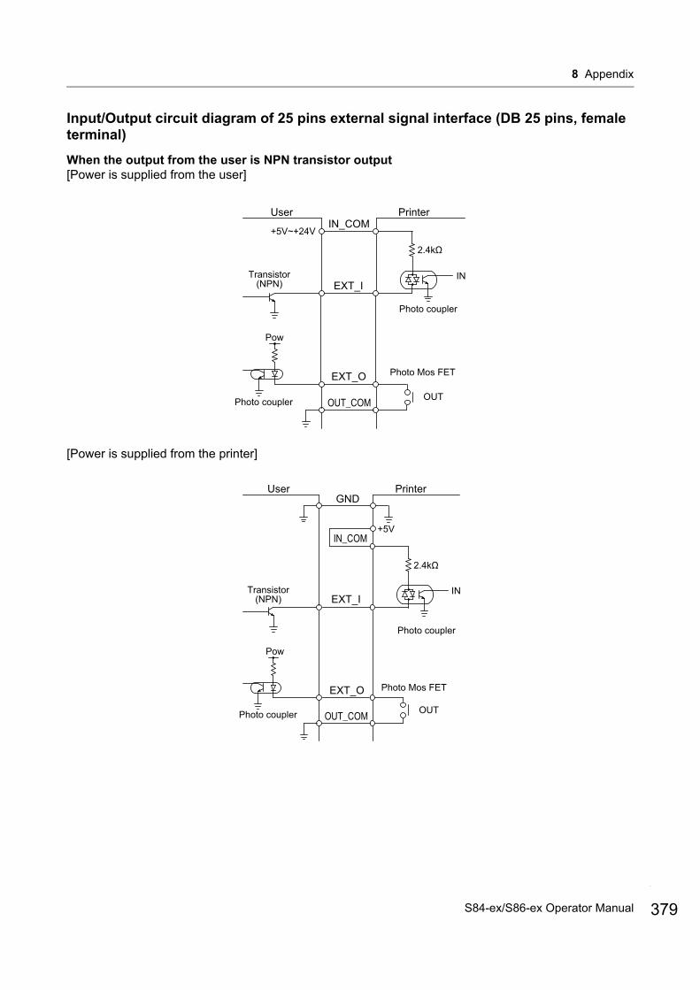
8 Appendix
Input/Output circuit diagram of 25 pins external signal interface (DB 25 pins, female terminal)
When the output from the user is NPN transistor output[Power is supplied from the user]
[Power is supplied from the printer]
PrinterUser
IN
Photo coupler
Transistor(NPN)
IN_COM
Photo Mos FET
EXT_I
EXT_O
OUT_COM
+5V~+24V
Pow
Photo coupler OUT
PrinterUser
IN
Photo coupler
Transistor(NPN)
IN_COM
Photo Mos FET
EXT_I
EXT_O
OUT_COM
+5V
Pow
Photo coupler OUT
GND
379S84-ex/S86-ex Operator Manual
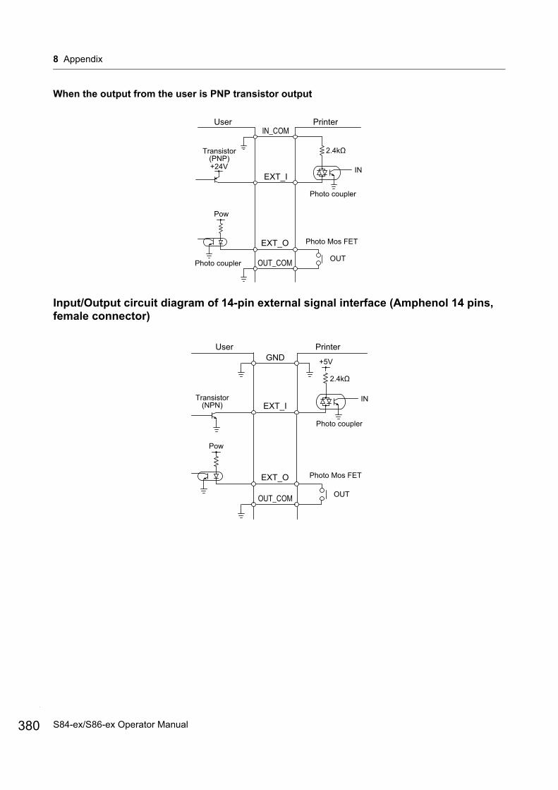
8 Appendix
380
When the output from the user is PNP transistor output
Input/Output circuit diagram of 14-pin external signal interface (Amphenol 14 pins, female connector)
PrinterUser
IN
Photo coupler
Transistor(PNP)
IN_COM
Photo Mos FET
EXT_I
EXT_O
OUT_COM
+24V
Pow
Photo coupler OUT
PrinterUser
IN
Photo coupler
Transistor(NPN)
Photo Mos FET
EXT_I
EXT_O
OUT_COM
+5V
Pow
OUT
GND
S84-ex/S86-ex Operator Manual
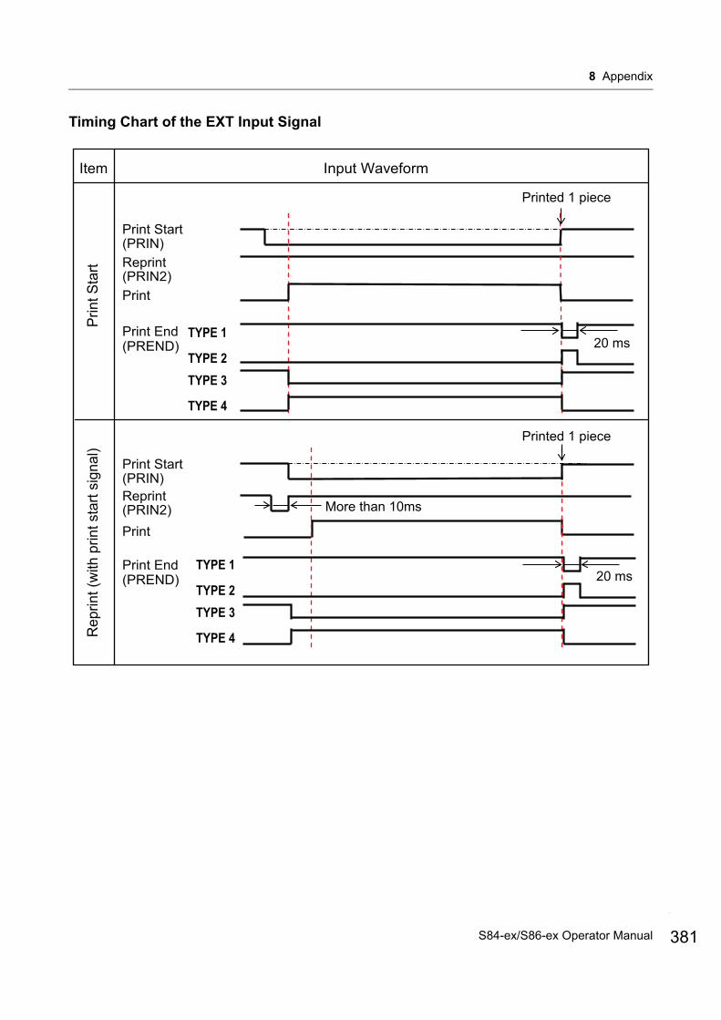
8 Appendix
Timing Chart of the EXT Input Signal
Input Waveform
Print Start
Prin
t Sta
rtR
eprin
t (w
ith p
rint s
tart
sign
al)
TYPE 1
TYPE 2TYPE 3
TYPE 4
TYPE 1
TYPE 2TYPE 3
TYPE 4
Printed 1 piece
Printed 1 piece
Reprint
Print End
(PRIN)
(PRIN2)
(PREND)
Print Start
Reprint
Print End
(PRIN)
(PRIN2)
(PREND)
Item
More than 10ms
20 ms
20 ms
381S84-ex/S86-ex Operator Manual

8 Appendix
382
Power ON
20 ms
20 ms
Backfeed BackfeedPrint 1st label Print 2nd label
Head check
Label feed
External signal
PREND(TYPE1)
Operation
PRIN
PREND(TYPE2)
PREND(TYPE3)
PREND(TYPE4)
Home position(3 pin)
Waiting time until printer recognizes PRIN signal
*1
*1 Maintain PRIN signal until PREND signal is output.
Dispenser input(9 pin)
When backfeed is complete, Home position goes Low until the Print Start is initiated and then it goes back High.
After Dispenser input becomes High, backfeed starts
When the label is removed from the dispense area, the Dispenser Input is initiated by the applicator.
*When the printer is set to Dispenser Input Mode it should backfeed upon recieving Print Start no matter the Dispense Input has been triggered or not.
*1
Input Waveform
PR
IN (D
ispe
nser
)
Item
S84-ex/S86-ex Operator Manual
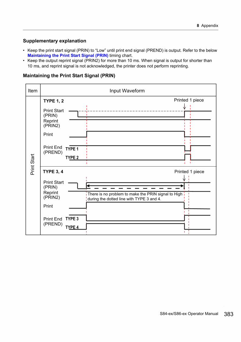
8 Appendix
Supplementary explanation
• Keep the print start signal (PRIN) to “Low” until print end signal (PREND) is output. Refer to the below Maintaining the Print Start Signal (PRIN) timing chart.
• Keep the output reprint signal (PRIN2) for more than 10 ms. When signal is output for shorter than 10 ms, and reprint signal is not acknowledged, the printer does not perform reprinting.
Maintaining the Print Start Signal (PRIN)
Input WaveformItem
Prin
t Sta
rt
Printed 1 piece
Print Start
Reprint
Print End
(PRIN)
(PRIN2)
(PREND)
TYPE 1, 2
TYPE 1
TYPE 2
TYPE 3, 4
Print Start
Reprint
Print End
(PRIN)
(PRIN2)
(PREND)TYPE 3
TYPE 4
Printed 1 piece
There is no problem to make the PRIN signal to High during the dotted line with TYPE 3 and 4.
383S84-ex/S86-ex Operator Manual
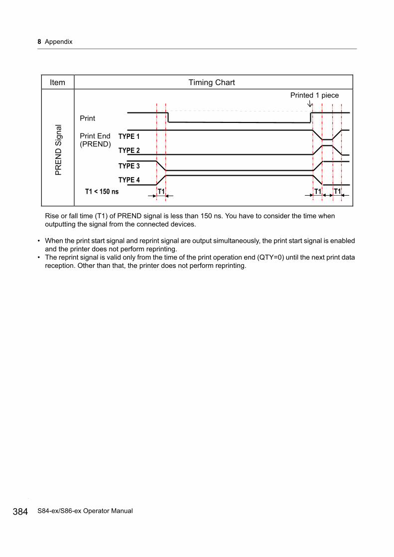
8 Appendix
384
Rise or fall time (T1) of PREND signal is less than 150 ns. You have to consider the time when outputting the signal from the connected devices.
• When the print start signal and reprint signal are output simultaneously, the print start signal is enabled and the printer does not perform reprinting.
• The reprint signal is valid only from the time of the print operation end (QTY=0) until the next print data reception. Other than that, the printer does not perform reprinting.
Timing ChartItem
PREN
D S
igna
l
Print End
(PREND)TYPE 1
TYPE 2
TYPE 3
TYPE 4
Printed 1 piece
T1 T1 T1T1 < 150 ns
S84-ex/S86-ex Operator Manual
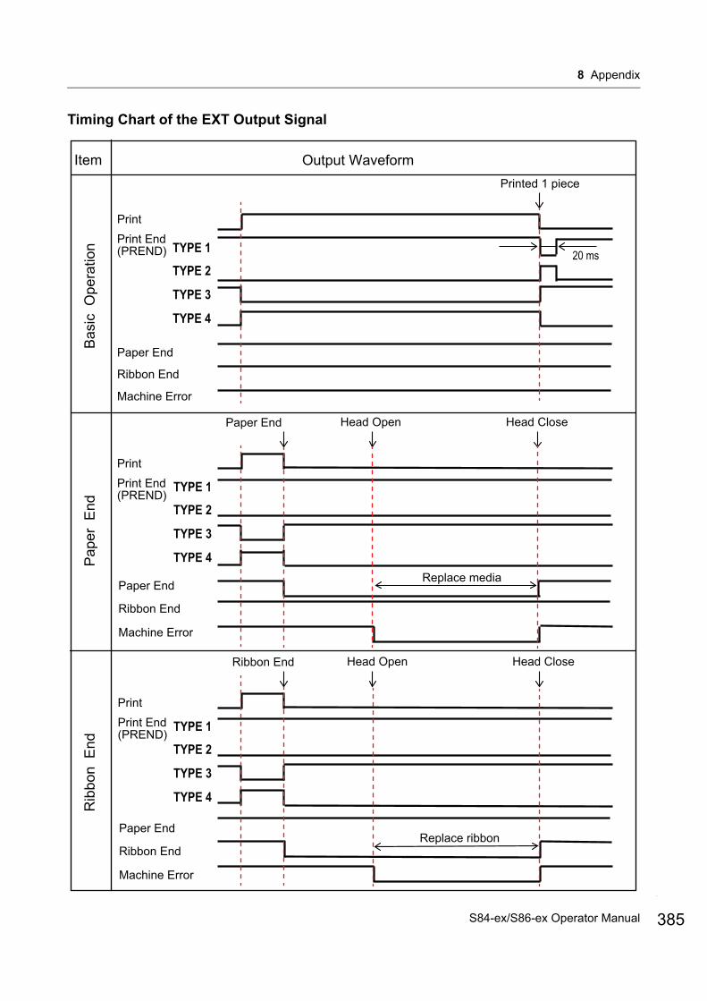
8 Appendix
Timing Chart of the EXT Output Signal
Item Output WaveformPrinted 1 piece
(PREND)Print EndPrint
Pap
er E
ndR
ibbo
n E
ndB
asic
Ope
ratio
n
Paper End
Ribbon End
Machine Error
Head Close
Paper End
Ribbon End
Paper End Head Open
Replace media
Replace ribbon
Machine Error
(PREND)Print EndPrint
Paper End
Ribbon End
Machine Error
(PREND)Print EndPrint
Head CloseRibbon End Head Open
TYPE 1
TYPE 2
TYPE 3
TYPE 4
TYPE 1
TYPE 2
TYPE 3
TYPE 4
TYPE 1
TYPE 2
TYPE 3
TYPE 4
20 ms
385S84-ex/S86-ex Operator Manual
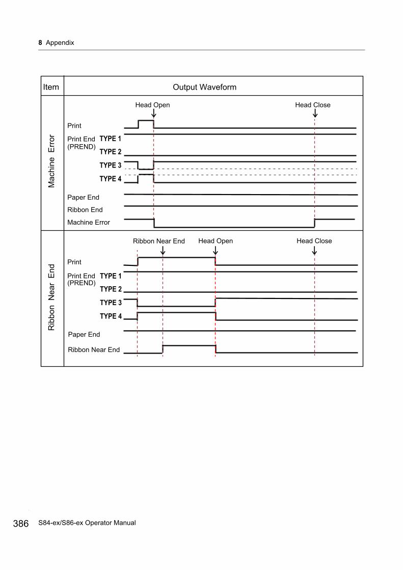
8 Appendix
386
Item Output Waveform
(PREND)Print End
Rib
bon
Nea
r E
ndM
achi
ne E
rror
Paper End
Ribbon End
Machine Error
Paper End
Ribbon Near End
(PREND)Print End
Head Open Head Close
Ribbon Near End Head Open Head Close
TYPE 1
TYPE 2
TYPE 3
TYPE 4
TYPE 1
TYPE 2
TYPE 3
TYPE 4
S84-ex/S86-ex Operator Manual

8 Appendix
Item Output Waveform
Onl
ine
Online
(PREND)Print End
Head Open Head Close Press LINE button
TYPE 1
TYPE 2
TYPE 3
TYPE 4
Print Data
MODE 1
MODE 2
Select MODE1 or MODE2 in the EXT 9PIN SELECT display of the SERVICE MODE menu.
Paper End
387S84-ex/S86-ex Operator Manual
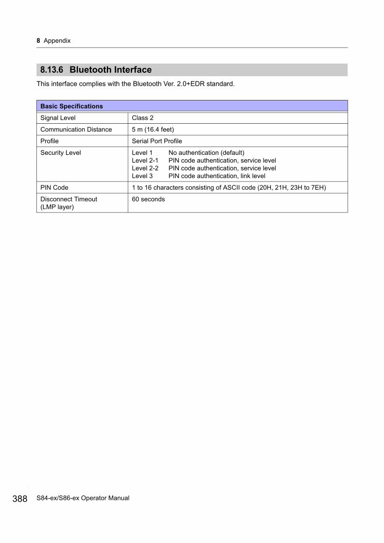
8 Appendix
388
8.13.6 Bluetooth Interface
This interface complies with the Bluetooth Ver. 2.0+EDR standard.
Basic Specifications
Signal Level Class 2
Communication Distance 5 m (16.4 feet)
Profile Serial Port Profile
Security Level Level 1 No authentication (default)Level 2-1 PIN code authentication, service levelLevel 2-2 PIN code authentication, service levelLevel 3 PIN code authentication, link level
PIN Code 1 to 16 characters consisting of ASCII code (20H, 21H, 23H to 7EH)
Disconnect Timeout (LMP layer)
60 seconds
S84-ex/S86-ex Operator Manual
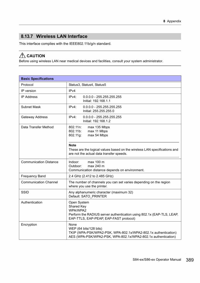
8 Appendix
8.13.7 Wireless LAN Interface
This interface complies with the IEEE802.11b/g/n standard.
CAUTIONBefore using wireless LAN near medical devices and facilities, consult your system administrator.
Basic Specifications
Protocol Status3, Status4, Status5
IP version IPv4
IP Address IPv4: 0.0.0.0 - 255.255.255.255Initial: 192.168.1.1
Subnet Mask IPv4: 0.0.0.0 - 255.255.255.255Initial: 255.255.255.0
Gateway Address IPv4: 0.0.0.0 - 255.255.255.255Initial: 192.168.1.2
Data Transfer Method 802.11n: max 135 Mbps802.11b: max 11 Mbps802.11g: max 54 Mbps
NoteThese are the logical values based on the wireless LAN specifications and are not the actual data transfer speeds.
Communication Distance Indoor: max 100 mOutdoor: max 240 mCommunication distance depends on environment.
Frequency Band 2.4 GHz (2.412 to 2.485 GHz)
Communication Channel The number of channels you can set varies depending on the region where you use the printer.
SSID Any alphanumeric character (maximum 32)Default: SATO_PRINTER
Authentication Open SystemShared KeyWPA/WPA2Perform the RADIUS server authentication using 802.1x (EAP-TLS, LEAP, EAP-TTLS, EAP-PEAP, EAP-FAST protocol)
Encryption NoneWEP (64 bits/128 bits)TKIP (WPA-PSK/WPA2-PSK, WPA-802.1x/WPA2-802.1x authentication)AES (WPA-PSK/WPA2-PSK, WPA-802.1x/WPA2-802.1x authentication)
389S84-ex/S86-ex Operator Manual
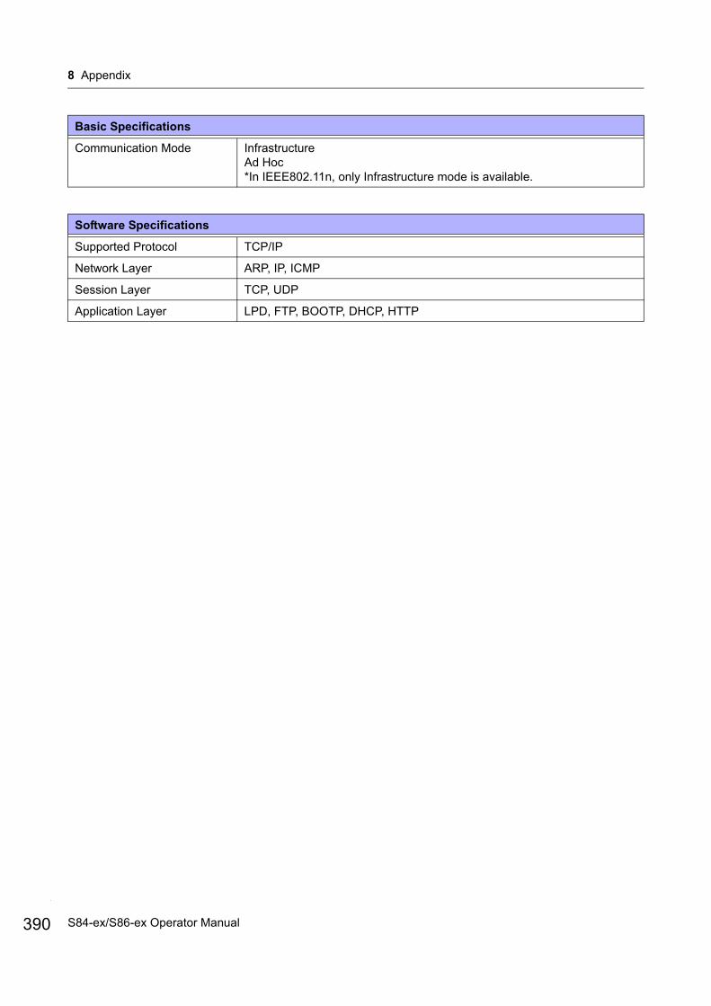
8 Appendix
390
Communication Mode InfrastructureAd Hoc*In IEEE802.11n, only Infrastructure mode is available.
Software Specifications
Supported Protocol TCP/IP
Network Layer ARP, IP, ICMP
Session Layer TCP, UDP
Application Layer LPD, FTP, BOOTP, DHCP, HTTP
Basic Specifications
S84-ex/S86-ex Operator Manual
8 Appendix
This page is intentionally left blank.
391S84-ex/S86-ex Operator Manual

Extensive contact information for worldwide SATO operations can be found on the Internet at www.satoworldwide.com
Recommended