R&S®HMC804xPower SupplySCPI Programmers Manual
SCPI
Pro
gram
mer
s M
anua
l
Test
& M
easu
rem
ent
Vers
ion
02
*5800568202*5800568202
SCPI Commands R&S®HMC804x Remote Control
2
SCPI Programmers Manual
Inhalt 1 Introduction / Basics ..................................................................................................................... 3 1.1 Remote Control Interfaces .............................................................................................................. 3 1.1.1 USB Interface .................................................................................................................................. 3 1.1.2 Ethernet (LAN) Interface ................................................................................................................. 4 1.1.4 GPIB Interface (IEC/IEEE Bus Interface) .......................................................................................... 5 1.2 Setting Up a Network (LAN) Connection ....................................................................................... 5 1.2.1 Connecting the Instrument to the Network ................................................................................... 5 1.2.2 ConfiguringLANParameters .......................................................................................................... 6 1.3 Switching to Remote Control .......................................................................................................... 8 1.4 Messages and Command Structure ............................................................................................... 8 1.4.1 Messages ........................................................................................................................................ 8 1.4.2 SCPI Command Structure ............................................................................................................... 9 1.5 Command Sequence and Synchronization ................................................................................... 13 1.5.1 Preventing Overlapping Execution ................................................................................................ 13 1.6 Status Reporting System .............................................................................................................. 14 1.6.1 Structure of a SCPI Status Register .............................................................................................. 14 17 2 Command Reference .................................................................................................................... 19 2.1 Common Commands .................................................................................................................... 19 2.2 System related commands ........................................................................................................ 22 2.3 Display commands ..................................................................................................................... 24 2.4 Trigger commands ..................................................................................................................... 24 2.5 ConfigurationCommands .......................................................................................................... 25 2.5.1 Channel selection ....................................................................................................................... 25 2.5.2 Voltage setting ........................................................................................................................... 26 2.5.3 Current setting ........................................................................................................................... 27 2.5.4 Combined setting of voltage and current ................................................................................... 29 2.5.5 Output setting ............................................................................................................................ 30 2.5.6 Fuse setting ................................................................................................................................ 32 2.5.7 OVP setting ................................................................................................................................ 34 2.5.8 OPP setting ................................................................................................................................ 36 2.6 Measurement Commands ......................................................................................................... 38 2.7 Arbitrary commands .................................................................................................................. 39 2.8 Advanced operating functions ................................................................................................... 43 2.8.1 Analog In .................................................................................................................................... 43 2.8.2 EasyRamp .................................................................................................................................. 45 2.8.3 Sequencing ................................................................................................................................ 46 2.9 Data and File Management ........................................................................................................ 48 2.9.1 Logging Example of CH1 and CH2 ............................................................................................... 54 2.10 Status Reporting ....................................................................................................................... 56 2.10.1 STATus:OPERation Register ....................................................................................................... 56 2.10.2 STATus:QUEStionable Registers ................................................................................................ 57 3 SCPI Command List ................................................................................................................... 60
SCPI Commands R&S®HMC804x Remote Control
3
Introduction / Basics
SCPI Programmers Manual
1 Introduction / BasicsThis chapter provides basic information on operating an instrument via remote control.
1.1 Remote Control Interfaces
For remote control, LAN / USB (standard interface) or GPIB (optional interface) can be used. The optional GPIB interface has its own interface module slot on the rear panel of the R&S®HMC804x.
NOTICE Within this interface description, the term GPIB is used as a synonym for the IEC/IEEE
bus interface.
SCPI (Standard Commands for Programmable Instruments) SCPI commands - messages - are used for remote control. Commands that are not taken from the SCPI standard follow the SCPI syntax rules.
1.1.1 USB Interface
In addition to a LAN interface, the R&S®HMC804x includes a USB device port. For this interface, the user can select if the instrument is accessed via virtual COM port (VCP) or via USB TMC class. The traditional version of the VCP allows the user to communicate with the R&S®HMC804x using any terminal program via SCPI commands once the corresponding Windows drivers have been installed. Naturally, the free software “HMExplorer” is also available for the R&S®HMC804x. This Windows application offers the R&S®HMC804x a terminal function or the option to create screenshots.
The modern alternative to the virtual COM port is to remote control the R&S®HMC804x via USB TMC class. TMC stands for “Test & Measurement Class” which indicates that the connected measurement instrument can be recognized without special Windows drivers if VISA drivers are installed and that it can be used directly in corresponding environments. The GPIB interface servesasmodeltothestructureoftheTMCdesign.AmajorbenefitoftheUSBTMCclassisthatbysamplingspecificregistersthecontrollingsoftwarecandetermineifcommandshavebeen terminated and if they have been processed correctly. In contrast, the communication via VCP requires analysis and polling mechanisms within the controlling software which may signi-ficantlystraintheinterfaceofthemeasurementinstruments.TheTMCstatusregisterssolvethisproblem with the USB TMC in the same manner as is the case with the GPIB interface for the hardware, namely via corresponding control lines.
If you are using USB you need to install an USB driver, which can be downloaded free of charge from the R&S homepage.
SCPI Commands R&S®HMC804x Remote Control
4
Introduction / Basics
SCPI Programmers Manual
NOTICE The currently available USB driver is fully tested, functional and released for Windows
XP™, Windows Vista™, Windows 7™, Windows 8™ or Windows 10™, both as 32Bit or 64Bit versions.
The R&S®HMC804x USB interface has to be chosen in the HMC SETUP menu and does not need any setting.
NOTICE If the virtual COM port will be used, you have to install the virtual COM port driver. The
virtual COM port (VCP) will be activated in the PC device explorer.
1.1.2 Ethernet (LAN) Interface
The settings of the parameter will be done after selecting the menu item ETHERNET and the soft key PARAMETER.YoucansetafixIPadressoradynamicIPsettingviatheDHCPfunction.Please ask your IT department for the correct setting at your network.
IP addressTo set up the connection the IP address of the instrument is required. It is part of the resource string used by the program to identify and control the instrument. The resource string has the form:
TCPIP::‹IP_address›::‹IP_port›::SOCKET
The default port number for SCPI socket communication is 5025. IP address and port number are listed In the „Ethernet Settings“ of the R&S®HMC804x, see also: chapter1.2.2,“ConfiguringLAN Parameters“.
Example: If the instrument has the IP address 192.1.2.3; the valid resource string is:
TCPIP::192.1.2.3::5025::SOCKET
If the LAN is supported by a DNS server, the host name can be used instead of the IP address. The DNS server (Domain Name System server) translates the host name to the IP address. The resource string has the form:
TCPIP::‹host_name›::‹IP_port›::SOCKET
To assign a host name to the R&S®HMC804x, select SETUP button › Misc › Device name.
Example: If the host name is TEST1; the valid resource string is:
TCPIP::TEST1::5025::SOCKET
SCPI Commands R&S®HMC804x Remote Control
5
Introduction / Basics
SCPI Programmers Manual
NOTICE The end character must be set to linefeed (LF).
1.1.4 GPIB Interface (IEC/IEEE Bus Interface)
In addition to the GPIB functions which are available via USB TMC class, the R&S®HMC804x is optionally available with an integrated GPIB interface. This solution is particularly attractive for customers who already have an existing GPIB environment. With minimum efforts, an old instru-ment can be replaced by a model of the R&S®HMC804x.
To be able to control the instrument via the GPIB bus, the instrument and the controller must be linked by a GPIB bus cable. A GPIB bus card, the card drivers and the program libraries for the programming language must be provided in the controller. The controller addresses the instru-ment with the GPIB instrument address.
CharacteristicsThe GPIB interface is described by the following characteristics:• Up to 15 instruments can be connected• The total cable length is restricted to a maximum of 15m; the cable length between two
instruments should not exceed 2m.• A wired „OR“-connection is used if several instruments are connected in parallel.
GPIB Instrument AddressIn order to operate the instrument via remote control, it must be addressed using the GPIB address. The remote control address is factory-set to 20, but it can be changed in the network environment settings or in the „Setup“ menu under „Interface --> Parameter“. For remote con-trol, a GPIB address from 0 to 30 are allowed. The GPIB address is maintained after a reset of the instrument settings.
1.2 Setting Up a Network (LAN) Connection
1.2.1 Connecting the Instrument to the Network
The network card can be operated with a 10 Mbps Ethernet IEEE 802.3 or a 100 Mbps Ethernet IEEE 802.3u interface.
NOTICE Risk of network failure
Before connecting the instrument to the network or configuring the network, consult your network administrator. Errors may affect the entire network.
SCPI Commands R&S®HMC804x Remote Control
6
Introduction / Basics
SCPI Programmers Manual
NOTICE To establish a network connection, connect a commercial RJ-45 cable to one of the
LAN ports of the instrument and to a PC.
1.2.2 Configuring LAN Parameters
Depending on the network capacities, the TCP/IP address information for the instrument can be obtained in different ways.• Automatically: DHCP or AutoIP. All address information can be assigned automatically.• Manually: the address must be set manually.
Bydefault,theinstrumentisconfiguredtouseautomaticallyconfigurationandobtainalladdressinformation automatically. This means that it is safe to establish a physical connection to the LAN withoutanypreviousinstrumentconfiguration.
NOTICE If DHCP is used and the system cannot assign an IP address to the R&S HMC804x (for
instance, if no Ethernet cable is connected or the network does not support DHCP), it may take up to three minutes until a timeout allows the interface to be configured again.
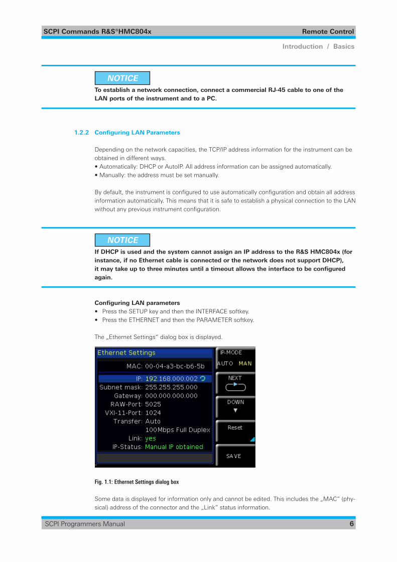
Configuring LAN parameters• Press the SETUP key and then the INTERFACE softkey.• Press the ETHERNET and then the PARAMETER softkey.
The „Ethernet Settings“ dialog box is displayed.
Fig. 1.1: Ethernet Settings dialog box
Some data is displayed for information only and cannot be edited. This includes the „MAC“ (phy-sical) address of the connector and the „Link“ status information.
SCPI Commands R&S®HMC804x Remote Control
7
Introduction / Basics
SCPI Programmers Manual
• DefinetheIPaddressoftheinstrumentbyenteringeachofthefourblocksindividually(ma-nual mode) or choose the automatic IP-Mode. a) Inmanualmode(MAN)definethefirstblocknumberusingtheknob. b) PressNexttomovetothenextblockanddefinethenumber. c) When the IP address is complete, press Down to continue with the next setting.
• Definethe„Subnetmask“and„Gateway“inthesameway.
• Select the „RAW Port“ - the port number for SCPI socket communication.
• Select the „VXI-11- Port“ used by the instrument.
• Select the „Transfer“ mode. This mode can either be determined automatically („Auto“ set-ting), or you can select a combination of a transfer rate and half or full duplex manually.
• Press SAVE to save the LAN parameters.
NOTICE The „Link“ and „IP-Status“ information at the bottom of the dialog box indicates
whether a LAN connection was established successfully.
Checking LAN and SCPI connection• Check the LAN connection using ping: ping xxx.yyy.zzz.xxx.
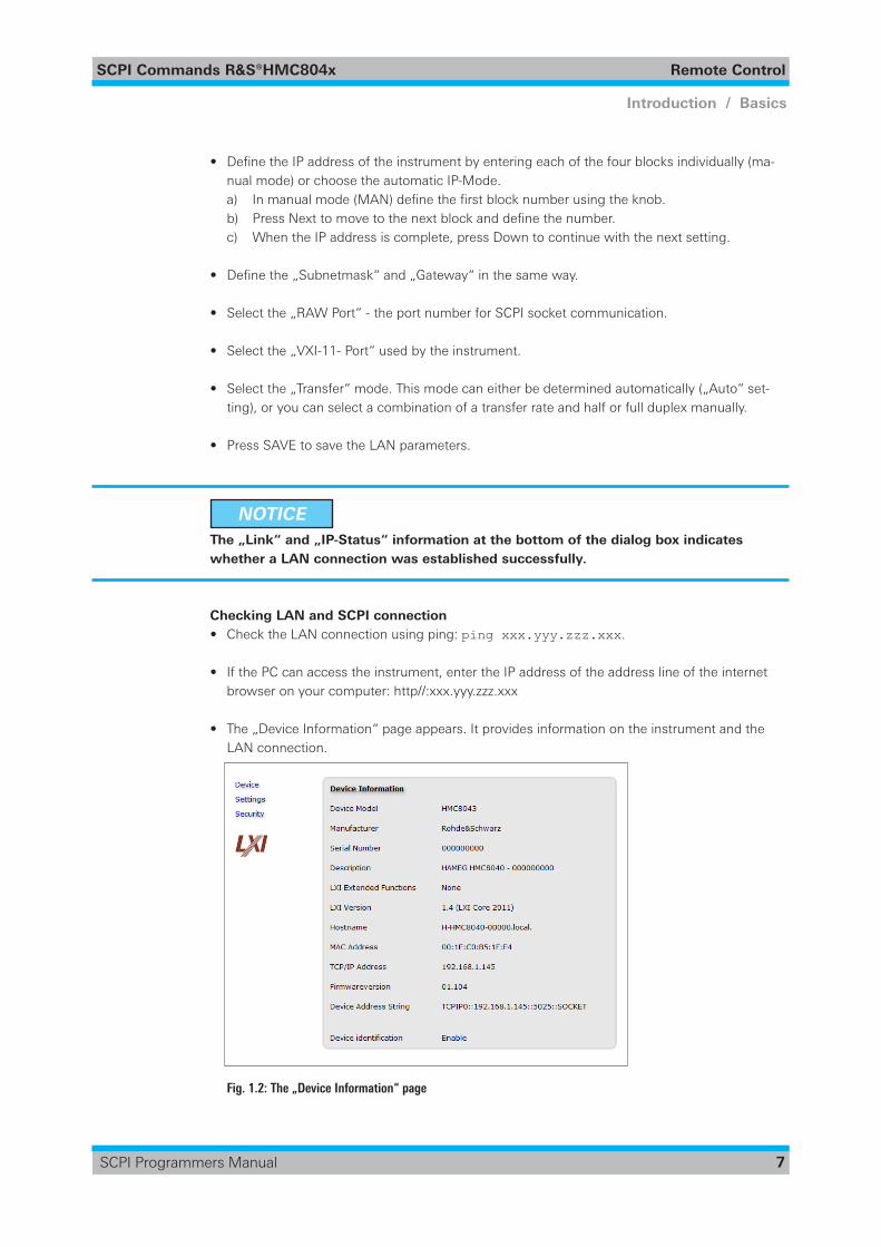
• If the PC can access the instrument, enter the IP address of the address line of the internet browser on your computer: http//:xxx.yyy.zzz.xxx
• The „Device Information“ page appears. It provides information on the instrument and the LAN connection.
Fig. 1.2: The „Device Information“ page
SCPI Commands R&S®HMC804x Remote Control
8
Introduction / Basics
SCPI Programmers Manual
1.3 Switching to Remote Control
When you switch on the instrument, it is always in manual operation state („local“ state) and can be operated via the front panel. When you send a command from the control computer, it will be received and executed by the instrument. The display remains on, manual operation via the front panel is always possible.
1.4 Messages and Command Structure
1.4.1 Messages
Instrument messages are employed in the same way for all interfaces, if not indicated otherwise in the description.See also:• Structure and syntax of the instrument messages: chapter 1.4.2, „SCPI Command Structure“.• Detailed description of all messages: chapter 2, „Command Reference“.
There are different types of instrument messages:• Commands• Instrument responses
CommandsCommands (program messages) are messages which the controller sends to the instrument. They operate the instrument functions and request information. The commands are subdivided according to two criteria:
According to the instrument effect:• Setting commands cause instrument settings such as a reset of the instrument or setting the
frequency. • Queriescausedatatobeprovidedforremotecontrol,e.g.foridentificationoftheinstrument
or polling a parameter value. Queries are formed by appending a question mark to the com-mand header.
According to their definition in standards:• ThefunctionandsyntaxoftheCommoncommandsarepreciselydefinedinstandardIEEE
488.2. They are employed identically on all instruments (if implemented). They refer to func-tions such as management of the standardized status registers, reset and self test.
• Instrument control commands refer to functions depending on the features of the instrument such as voltage settings. Many of these commands have also been standardized by the SCPI committee. These commands are marked as „SCPI compliant“ in the command reference chapters.CommandswithoutthisSCPIlabelaredevice-specific,however,theirsyntaxfollowsSCPI rules as permitted by the standard.
Instrument responsesInstrument responses (response messages and service requests) are messages which the instru-ment is sent to the controller after a query. They can contain measurement results, instrument settings and information on the instrument status.
SCPI Commands R&S®HMC804x Remote Control
9
Introduction / Basics
SCPI Programmers Manual
GPIB Interface MessagesInterface messages are transmitted to the instrument on the data lines, with the attention line (ATN) being active (LOW). They are used for communication between the controller and the instrument and can only be sent by a computer which has the function of a GPIB bus controller. GPIB interface messages can be further subdivided into:• Universal commands: act on all instruments connected to the GPIB bus without previous
addressing• Addressed commands: only act on instruments previously addressed as listeners
Universal CommandsUniversal commands are encoded in the range 10 through 1F hex. They affect all instruments connected to the bus and do not require addressing. Addressed commands are encoded in the range 00 through 0F hex. They only affect instruments addressed as listeners.
1.4.2 SCPI Command Structure
SCPI commands consist of a so-called header and, in most cases, one or more parameters. The header and the parameters are separated by a „white space“ (ASCII code 0 to 9, 11 to 32 deci-mal, e.g. blank). The headers may consist of several mnemonics (keywords). Queries are formed by appending a question mark directly to the header.
Thecommandscanbeeitherdevice-specificordevice-independent(commoncommands).Commonanddevice-specificcommandsdifferintheirsyntax.
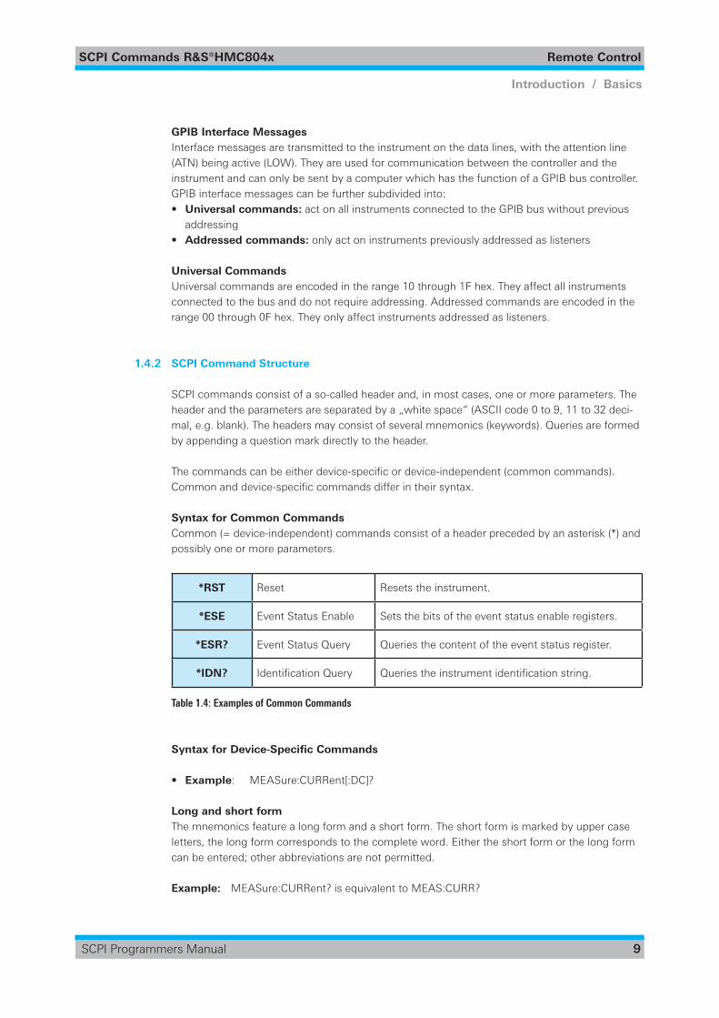
Syntax for Common CommandsCommon (= device-independent) commands consist of a header preceded by an asterisk (*) and possibly one or more parameters.
*RST Reset Resets the instrument.
*ESE Event Status Enable Sets the bits of the event status enable registers.
*ESR? Event Status Query Queries the content of the event status register.
*IDN? IdentificationQuery Queriestheinstrumentidentificationstring.
Table 1.4: Examples of Common Commands
Syntax for Device-Specific Commands
• Example: MEASure:CURRent[:DC]?
Long and short formThe mnemonics feature a long form and a short form. The short form is marked by upper case letters, the long form corresponds to the complete word. Either the short form or the long form can be entered; other abbreviations are not permitted.
Example: MEASure:CURRent? is equivalent to MEAS:CURR?
SCPI Commands R&S®HMC804x Remote Control
10
Introduction / Basics
SCPI Programmers Manual
NOTICE Case-insensitivity Upper case and lower case notation only serves to distinguish the two forms in the
manual, the instrument itself is case-insensitive.
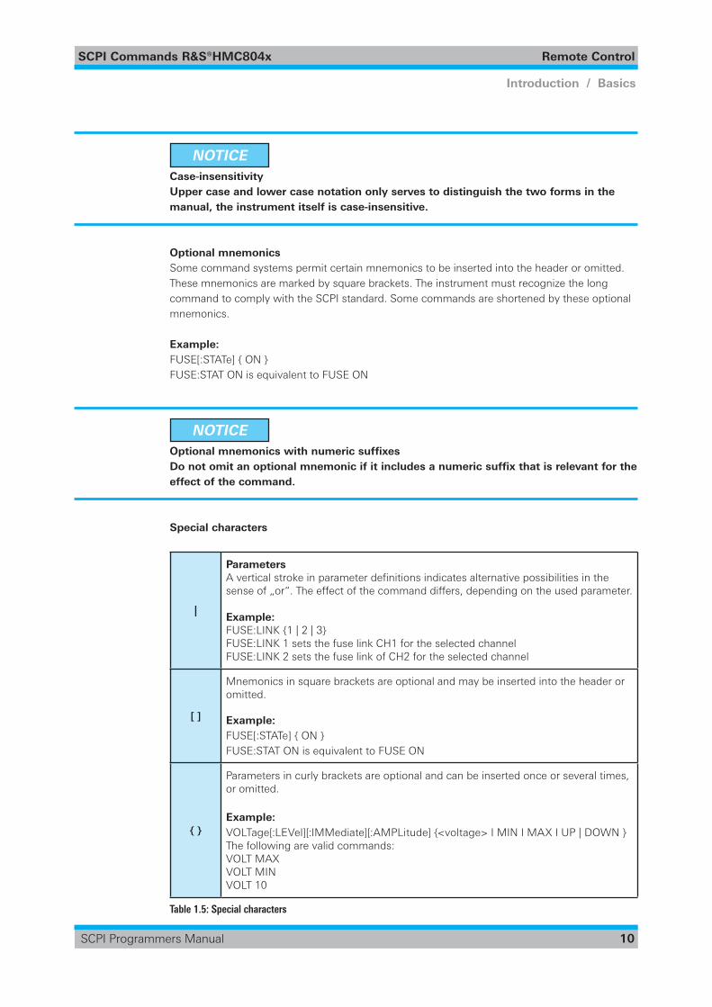
Optional mnemonicsSome command systems permit certain mnemonics to be inserted into the header or omitted. These mnemonics are marked by square brackets. The instrument must recognize the long command to comply with the SCPI standard. Some commands are shortened by these optional mnemonics.
Example: FUSE[:STATe] { ON }FUSE:STAT ON is equivalent to FUSE ON
NOTICE Optional mnemonics with numeric suffixes Do not omit an optional mnemonic if it includes a numeric suffix that is relevant for the
effect of the command.
Special characters
|
ParametersAverticalstrokeinparameterdefinitionsindicatesalternativepossibilitiesinthesense of „or“. The effect of the command differs, depending on the used parameter.
Example:FUSE:LINK {1 | 2 | 3}FUSE:LINK 1 sets the fuse link CH1 for the selected channelFUSE:LINK 2 sets the fuse link of CH2 for the selected channel
[ ]
Mnemonics in square brackets are optional and may be inserted into the header or omitted.
Example: FUSE[:STATe] { ON }FUSE:STAT ON is equivalent to FUSE ON
{ }
Parameters in curly brackets are optional and can be inserted once or several times, or omitted.
Example: VOLTage[:LEVel][:IMMediate][:AMPLitude] {<voltage> I MIN I MAX I UP | DOWN }The following are valid commands:VOLT MAXVOLT MINVOLT 10
Table 1.5: Special characters
SCPI Commands R&S®HMC804x Remote Control
11
Introduction / Basics
SCPI Programmers Manual
SCPI ParametersMany commands are supplemented by a parameter or a list of parameters. The parameters must be separated from the header by a „white space“ (ASCII code 0 to 9, 11 to 32 decimal, e.g. blank). Allowed parameters are:
• Numeric values• Special numeric values• Boolean parameters• Text• Character strings
Theparametersrequiredforeachcommandandtheallowedrangeofvaluesarespecifiedinthecommand description.
Numeric valuesNumeric values can be entered in any form, i.e. with sign, decimal point and exponent. Values exceeding the resolution of the instrument are rounded up or down. The mantissa may comprise up to 255 characters, the exponent must lie inside the value range -32000 to 32000. The expo-nent is introduced by an „E“ or „e“. Entry of the exponent alone is not allowed.
Example: VOLT 500mV = VOLT 500e-3
Special numeric valuesThe text listed below are interpreted as special numeric values. In the case of a query, the nume-ric value is provided.• MIN/MAX• MINimum and MAXimum denote the minimum and maximum value.
Example:VOLT 10VOLT?, Response: 1.0000E+01
Queries for special numeric valuesThe numeric values associated to MAXimum/MINimum can be queried by adding the correspon-ding mnemonics to the command. They must be entered following the quotation mark.
Example:VOLT:PROT? MAXReturns the maximum numeric value.
Boolean ParametersBoolean parameters represent two states. The „ON“ state (logically true) is represented by „ON“ or a numeric value 1. The „OFF“ state (logically untrue) is represented by „OFF“ or the numeric value 0. The numeric values are provided as the response for a query.
Example: OUTPut[:STATe] ONOUTPut[:STATe]?, Response: 1
SCPI Commands R&S®HMC804x Remote Control
12
Introduction / Basics
SCPI Programmers Manual
Text parametersText parameters observe the syntactic rules for mnemonics, i.e. they can be entered using a short or long form. Like any parameter, they have to be separated from the header by a white space. In the case of a query, the short form of the text is provided.
Example:HCOPy:FORMat BMPHCOPy:FORMat?, Response: BMP
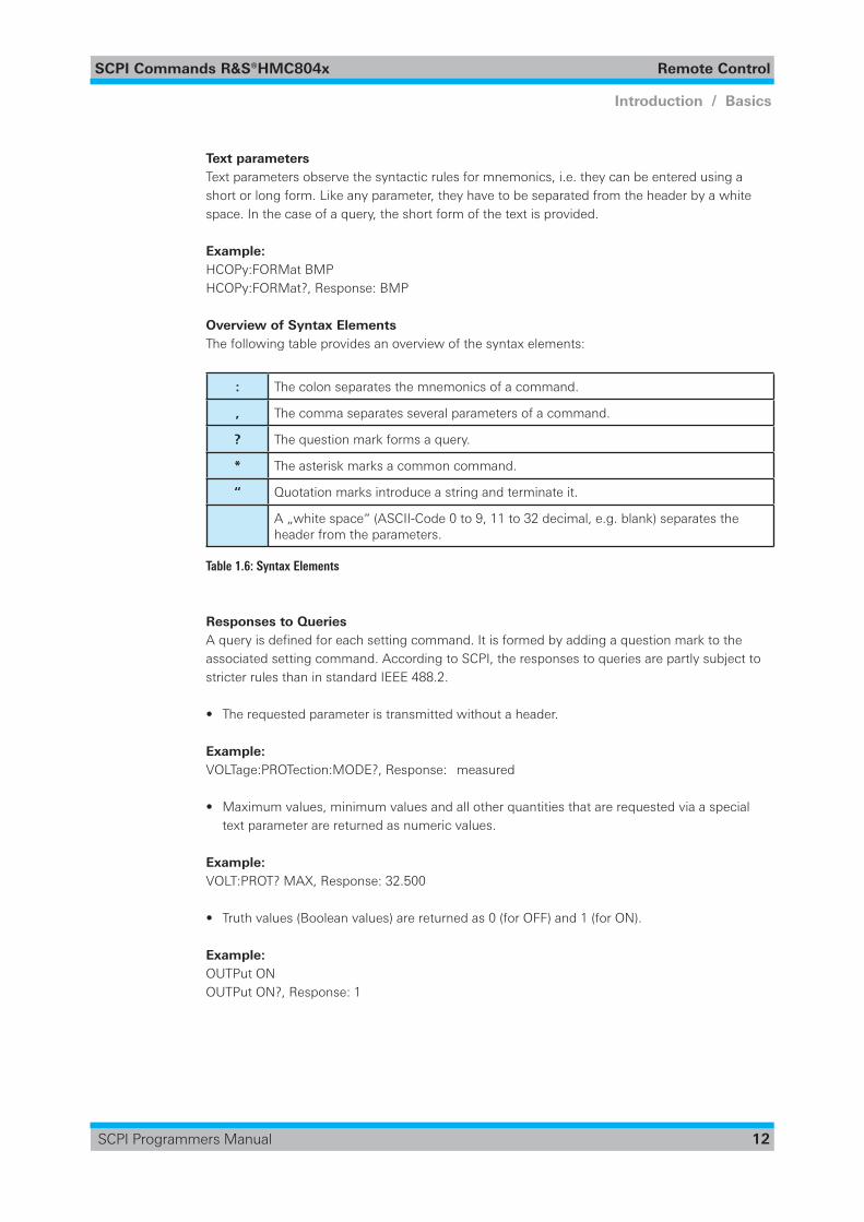
Overview of Syntax ElementsThe following table provides an overview of the syntax elements:
: The colon separates the mnemonics of a command.
, The comma separates several parameters of a command.
? The question mark forms a query.
* The asterisk marks a common command.
“ Quotation marks introduce a string and terminate it.
A „white space“ (ASCII-Code 0 to 9, 11 to 32 decimal, e.g. blank) separates the header from the parameters.
Table 1.6: Syntax Elements
Responses to QueriesAqueryisdefinedforeachsettingcommand.Itisformedbyaddingaquestionmarktotheassociated setting command. According to SCPI, the responses to queries are partly subject to stricter rules than in standard IEEE 488.2.
• The requested parameter is transmitted without a header.
Example: VOLTage:PROTection:MODE?, Response: measured
• Maximum values, minimum values and all other quantities that are requested via a special text parameter are returned as numeric values.
Example:VOLT:PROT? MAX, Response: 32.500
• Truth values (Boolean values) are returned as 0 (for OFF) and 1 (for ON).
Example:OUTPut ONOUTPut ON?, Response: 1
SCPI Commands R&S®HMC804x Remote Control
13
Introduction / Basics
SCPI Programmers Manual
1.5 Command Sequence and Synchronization
Asequentialcommandfinishestheexecutionbeforethenextcommandisstarting.Inordertomake sure that commands are actually carried out in a certain order, each command must be sent in a separate command line.
NOTICE As a general rule, send commands and queries in different program messages.
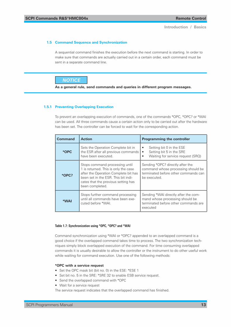
1.5.1 Preventing Overlapping Execution
To prevent an overlapping execution of commands, one of the commands *OPC, *OPC? or *WAI can be used. All three commands cause a certain action only to be carried out after the hardware has been set. The controller can be forced to wait for the corresponding action.
Command Action Programming the controller
*OPCSets the Operation Complete bit in the ESR after all previous commands have been executed.
• Setting bit 0 in the ESE• Setting bit 5 in the SRE• Waiting for service request (SRQ)
*OPC?
Stops command processing until 1 is returned. This is only the case after the Operation Complete bit has been set in the ESR. This bit indi-cates that the previous setting has been completed.
Sending *OPC? directly after the command whose processing should be terminated before other commands can be executed.
*WAI
Stops further command processing until all commands have been exe-cuted before *WAI.
Sending *WAI directly after the com-mand whose processing should be terminated before other commands are executed
Table 1.7: Synchronization using *OPC, *OPC? and *WAI
Command synchronization using *WAI or *OPC? appended to an overlapped command is a good choice if the overlapped command takes time to process. The two synchronization tech-niques simply block overlapped execution of the command. For time consuming overlapped commands it is usually desirable to allow the controller or the instrument to do other useful work while waiting for command execution. Use one of the following methods:
*OPC with a service request• Set the OPC mask bit (bit no. 0) in the ESE: *ESE 1• Set bit no. 5 in the SRE: *SRE 32 to enable ESB service request.• Send the overlapped command with *OPC• Wait for a service requestTheservicerequestindicatesthattheoverlappedcommandhasfinished.
SCPI Commands R&S®HMC804x Remote Control
14
Introduction / Basics
SCPI Programmers Manual
*OPC? with a service request• Set bit no. 4 in the SRE: *SRE 16 to enable MAV service request.• Send the overlapped command with *OPC?• Wait for a service requestTheservicerequestindicatesthattheoverlappedcommandhasfinished.
Event Status Register (ESE)• Set the OPC mask bit (bit no. 0) in the ESE: *ESE 1• Send the overlapped command without *OPC, *OPC? or *WAI• Poll the operation complete state periodically (by means of a timer) using the sequence:
*OPC; *ESR?Areturnvalue(LSB)of1indicatesthattheoverlappedcommandhasfinished.*OPC? with short timeout• Send the overlapped command without *OPC, *OPC? or *WAI• Poll the operation complete state periodically (by means of a timer) using the sequence: ‹short
timeout›; *OPC?• Areturnvalue(LSB)of1indicatesthattheoverlappedcommandhasfinished.Incaseofa
timeout, the operation is ongoing.• Reset timeout to former value• Clear the error queue with SYStem:ERRor? to remove the „-410, Query interrupted“ entries.
Using several threads in the controller applicationAs an alternative, provided the programming environment of the controller application sup-ports threads, separate threads can be used for the application GUI and for controlling the instrument(s) via SCPI. A thread waiting for a *OPC? thus will not block the GUI or the communi-cation with other instruments.
1.6 Status Reporting System
The status reporting system stores all information on the current operating state of the instru-ment, and on errors which have occurred. This information is stored in the status registers and in the error queue. Both can be queried via GPIB bus or LAN interface (STATus... commands).
1.6.1 Structure of a SCPI Status Register
Each standard SCPI register consists of 2 or 3 parts (Event, Condition and Enable register). Each part has a width of 16 bits and has different functions. The individual bits are independent of each other, i.e. each hardware status is assigned a bit number which is valid for all 2 or 3 parts. Bit15(themostsignificantbit)issettozeroforallparts.Thusthecontentsoftheregisterpartscan be processed by the controller as positive integers.
A STATus:QUEStionable:INSTrument:ISUMmary1 exists as often as device channels are available (e.g. R&S®HMC8043 = 3 channels = 3 status register). Accordingly, the description text of the channel information changes in Fig. 1.1 (e.g. instrument 1 = channel 1, instrument 2 = channel 2 etc.).
SCPI Commands R&S®HMC804x Remote Control
15
Introduction / Basics
SCPI Programmers Manual
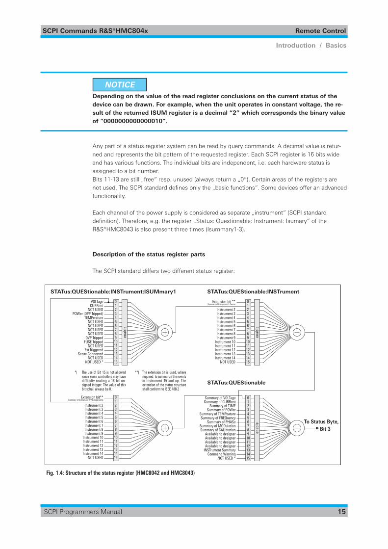
NOTICE Depending on the value of the read register conclusions on the current status of the
device can be drawn. For example, when the unit operates in constant voltage, the re-sult of the returned ISUM register is a decimal “2” which corresponds the binary value of “0000000000000010”.
Any part of a status register system can be read by query commands. A decimal value is retur-ned and represents the bit pattern of the requested register. Each SCPI register is 16 bits wide and has various functions. The individual bits are independent, i.e. each hardware status is assigned to a bit number.Bits 11-13 are still „free“ resp. unused (always return a „0“). Certain areas of the registers are not used. The SCPIstandarddefinesonlythe„basicfunctions“.Somedevicesofferanadvancedfunctionality.
Each channel of the power supply is considered as separate „instrument“ (SCPI standard definition).Therefore,e.g.theregister„Status:Questionable:Instrument:Isumary“oftheR&S®HMC8043 is also present three times (Isummary1-3).
Description of the status register parts
The SCPI standard differs two different status register:
VOLTage 0 CURRent 1 NOT USED 2 POWer (OPP Tripped) 3 TEMPerature 4 NOT USED 5 NOT USED 6 NOT USED 7 NOT USED 8 OVP Tripped 9 FUSE Tripped 10 NOT USED 11 Ext.Triggered 12 Sense Connected 13 NOT USED 14 NOT USED * 15
enab
le
Extension bit ** 0 Summary of Instrument 1 Events 1 Instrument 2 2 Instrument 3 3 Instrument 4 4 Instrument 5 5 Instrument 6 6 Instrument 7 7 Instrument 8 8 Instrument 9 9 Instrument 10 10 Instrument 11 11 Instrument 12 12 Instrument 13 13 Instrument 14 14 NOT USED 15
Extension bit** 0 Summary of Instrument 1 VOLTageEvents 1 Instrument 2 2 Instrument 3 3 Instrument 4 4 Instrument 5 5 Instrument 6 6 Instrument 7 7 Instrument 8 8 Instrument 9 9 Instrument 10 10 Instrument 11 11 Instrument 12 12 Instrument 13 13 Instrument 14 14 NOT USED 15
Summary of VOLTage 0 Summary of CURRent 1 Summary of TIME 2 Summary of POWer 3 Summary of TEMPeature 4 Summary of FREquency 5 Summary of PhaSe 6 Summary of MODulation 7 Summary of CaLibration 8 available to designer 9 available to designer 10 available to designer 11 available to designer 12 INSTrument Summary 13 Command Warning 14 NOT USED * 15
enab
leen
able
STATus:QUEStionable:INSTrument:ISUMmary1 STATus:QUEStionable:INSTrument
*** STATus:QUEStionable
To Status Byte, Bit 3
VOLTage 0 CURRent 1 NOT USED 2 POWer (OPP Tripped) 3 TEMPerature 4 NOT USED 5 NOT USED 6 NOT USED 7 NOT USED 8 OVP Tripped 9 FUSE Tripped 10 NOT USED 11 Ext.Triggered 12 Sense Connected 13 NOT USED 14 NOT USED * 15
enab
le
STATus:QUEStionable:INSTrument
*) The use of Bit 15 is not allowed since some controllers may have difficulty reading a 16 bit unsigned integer. The value of this bit shall always be 0.
To Status Byte, Bit 3
*) The use of Bit 15 is not allowed since some controllers may have difficulty reading a 16 bit un-signed integer. The value of this bit schall always be 0.
**) The extension bit is used, where required, to summarize the events in Instrument 15 and up. The extension of the status structure shall conform to IEEE 488.2
Fig. 1.4: Structure of the status register (HMC8042 and HMC8043)
SCPI Commands R&S®HMC804x Remote Control
16
Introduction / Basics
SCPI Programmers Manual
CONDition• The CONDition register queries the actual state of the instrument. If you want to query the
constant voltage or current mode, you have to use the CONDition register.
NOTICE The CONDition register delivers a „1“ (first bit set) in constant current mode (CC) and
a „2“ (second bit set) in constant voltage mode (CV).
If the correct channel is selected and the red LED of the channel button lights up (CC mode), the query of the CONDition register has to be deliver a „1“. Example:STAT:QUES:ISUM1:COND?
EVENt• The EVENt status register is set (1) until it is queried. After reading (query) the EVENt status
register is set to zero.
NOTICE The description of registers is only used for general explanation. Due to the complexity
we recommend the general accessible SCPI standard document for more detailed infor-mation.
For further descriptions of the status register, please refer to chapter 2.
Event Status Register (ESR) and Event Status Enable Register (ESE)TheESRisdefinedinIEEE488.2.ItcanbecomparedwiththeEVENt part of a SCPI register. The event status register can be read out using command *ESR?. The ESE corresponds to the ENA-Ble part of a SCPI register. If a bit is set in the ESE and the associated bit in the ESR changes from 0 to 1, the ESB bit in the STB is set. The ESE register can be set using the command *ESE and read using the command *ESE?.
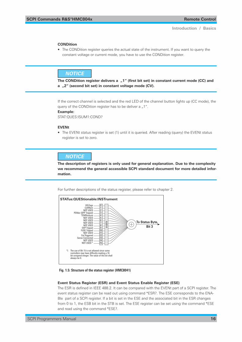
VOLTage 0 CURRent 1 NOT USED 2 POWer (OPP Tripped) 3 TEMPerature 4 NOT USED 5 NOT USED 6 NOT USED 7 NOT USED 8 OVP Tripped 9 FUSE Tripped 10 NOT USED 11 Ext.Triggered 12 Sense Connected 13 NOT USED 14 NOT USED * 15
enab
le
Extension bit ** 0 Summary of Instrument 1 Events 1 Instrument 2 2 Instrument 3 3 Instrument 4 4 Instrument 5 5 Instrument 6 6 Instrument 7 7 Instrument 8 8 Instrument 9 9 Instrument 10 10 Instrument 11 11 Instrument 12 12 Instrument 13 13 Instrument 14 14 NOT USED 15
Extension bit** 0 Summary of Instrument 1 VOLTageEvents 1 Instrument 2 2 Instrument 3 3 Instrument 4 4 Instrument 5 5 Instrument 6 6 Instrument 7 7 Instrument 8 8 Instrument 9 9 Instrument 10 10 Instrument 11 11 Instrument 12 12 Instrument 13 13 Instrument 14 14 NOT USED 15
Summary of VOLTage 0 Summary of CURRent 1 Summary of TIME 2 Summary of POWer 3 Summary of TEMPeature 4 Summary of FREquency 5 Summary of PhaSe 6 Summary of MODulation 7 Summary of CaLibration 8 available to designer 9 available to designer 10 available to designer 11 available to designer 12 INSTrument Summary 13 Command Warning 14 NOT USED * 15
enab
leen
able
STATus:QUEStionable:INSTrument:ISUMmary1 STATus:QUEStionable:INSTrument
*** STATus:QUEStionable
To Status Byte, Bit 3
VOLTage 0 CURRent 1 NOT USED 2 POWer (OPP Tripped) 3 TEMPerature 4 NOT USED 5 NOT USED 6 NOT USED 7 NOT USED 8 OVP Tripped 9 FUSE Tripped 10 NOT USED 11 Ext.Triggered 12 Sense Connected 13 NOT USED 14 NOT USED * 15
enab
le
STATus:QUEStionable:INSTrument
*) The use of Bit 15 is not allowed since some controllers may have difficulty reading a 16 bit unsigned integer. The value of this bit shall always be 0.
To Status Byte, Bit 3
Fig. 1.5: Structure of the status register (HMC8041)
SCPI Commands R&S®HMC804x Remote Control
17
Introduction / Basics
SCPI Programmers Manual
STATus:QUEStionable RegisterThis register contains information about different states which may occur. It can be read using the commands STATus:QUEStionable:CONDition? and STATus: QUEStionable[: EVENt]? .
Bit No. Meaning
0 VoltageThis bit is set while the instrument is in constant current mode (CC). This means that the voltage will be regulated and the current is constant.
1CurrentThis bit is set while the instrument is in constant voltage mode (CV). This means that the current is variable and the voltage is constant.
2 Not used
3 Not used
4Temperature overrangeThis bit is set if an over temperature occurs.
5-8 Not used
9OVP TrippedThis bit is set if the over voltage protection has tripped.
10Fuse TrippedThis bit is set if the fuse protection has tripped.
11 to 15 Not used
Table 1.8: Bits of the STATus:QUEStionable register (please refer to fig. 1.4)
Query of an instrument statusEach part of any status register can be read using queries.
There are two types of commands:• The common commands *ESR?, *IDN?, *STB? query the higher-level registers.• The commands of the STATus system query the SCPI registers (STATus:QUEStionable)
The returned value is always a decimal number that represents the bit pattern of the queried register. This number is evaluated by the controller program.
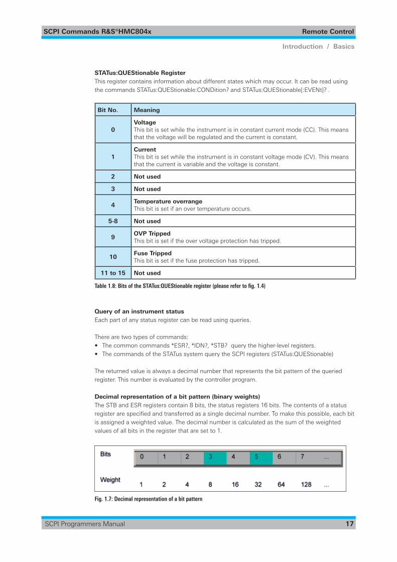
Decimal representation of a bit pattern (binary weights)The STB and ESR registers contain 8 bits, the status registers 16 bits. The contents of a status registerarespecifiedandtransferredasasingledecimalnumber.Tomakethispossible,eachbitis assigned a weighted value. The decimal number is calculated as the sum of the weighted values of all bits in the register that are set to 1.
Fig. 1.7: Decimal representation of a bit pattern

SCPI Commands R&S®HMC804x Remote Control
18
Introduction / Basics
SCPI Programmers Manual
Error QueueEach error state in the instrument leads to an entry in the error queue. The entries of the error queue are detailed plain text error messages that can be looked up in the error log or queried via remote control using SYSTem:ERRor[:NEXT]?. Each call of SYSTem:ERRor[:NEXT]? provides one entry from the error queue. If no error messages are stored, the instrument responds with 0, „No error“.
For further description of the error queue and the device error codes, please refer to chapter 2.
SCPI Commands R&S®HMC804x Remote Control
19
Introduction / Basics
SCPI Programmers Manual
2 Command ReferenceThis chapter provides the description of all remote commands available for oscilloscopes HMO series. The commands are sorted according to the menu structure of the instrument. A list of commands in alphabetical order ist given in the „List of Commands“ at the end of this documen-tation.
2.1 Common Commands
Common commands are described in the IEEE 488.2 (IEC 625-2) standard. These commands have the same effect and are employed in the same way on different devices.The headers of these commands consist of „*“ followed by three letters. Many common commands are related to the Status Reporting System.
Available common commands:
*CLS ........................................................................................................................................... 19*ESE <Value> ............................................................................................................................. 19*ESR? ......................................................................................................................................... 20*IDN? .......................................................................................................................................... 20*OPC ........................................................................................................................................... 20*RST ........................................................................................................................................... 20*SRE <Contents> ....................................................................................................................... 21*STB? ......................................................................................................................................... 21*TST? .......................................................................................................................................... 21*WAI ........................................................................................................................................... 21
*CLS CLear Status
Sets the status byte (STB), the standard event register (ESR) and the EVENt part of the QUE-Stionable to zero. The command does not alter the mask and transition parts of the registers. It clears the output buffer.
Usage: Setting only
*ESE <Value> Event Status Enable
Setstheeventstatusenableregistertothespecifiedvalue.Thequery*ESE?returnsthecontentsof the event status enable register in decimal form.
Parameters:<Value> Range: 0 to 255
SCPI Commands R&S®HMC804x Remote Control
20
Introduction / Basics
SCPI Programmers Manual
*ESR? Event Status Read
Returns the contents of the event status register in decimal form and subsequently sets the register to zero.
Return values:<Contents> Range: 0 to 255
Usage: Query only
*IDN? IDeNtification
Returnstheinstrumentidentificationstring.
Return values:<ID> ROHDE&SCHWARZ,‹devicetype›,‹serialnumber›,‹hardware›,‹firmwareversion›
Example: Rohde&Schwarz,HMC8043,000000000,HW42000000,SW01.000
Usage: Query only
*OPC OPeration Complete
Sets bit 0 in the event status register when all preceding commands have been executed. This bit can be used to initiate a service request. The query *OPC? writes a „1“ into the output buffer as soon as all preceding commands have been executed. This is used for command synchroniza-tion.
NOTICE The R&S®HMC804x does not support parallel processing of remote commands. If the
query *OPC? returns a „1“, the device is able to process new commands.
*RST ReSeT
Setstheinstrumenttoadefineddefaultstatus.
Usage: Setting only
SCPI Commands R&S®HMC804x Remote Control
21
Introduction / Basics
SCPI Programmers Manual
NOTICE We recommend to start a program by *RST in order to set the instrument to a defined
status prior to starting a program.
*SRE <Contents> Service Request Enable
Sets the service request enable register to the indicated value. This command determines under which conditions a service request is triggered. The query *SRE? returns a decimal value of the service request enable register which corresponds to the binary-weighted sum of all bits.
Parameters:<Contents> Contents of the service request enable register in decimal form. Bit 6 (MSS mask bit) is always 0.
Range: 0 to 255
NOTICE The SRE is an enable register. Consequently, there are no denotations about the bits.
This register conduce for the „OR“ combination of the bits in the status byte.
*STB? STatus Byte query
Returns the contents of the status byte in decimal form.
Usage: Query only
*TST? self TeST query
Triggers selftests of the instrument and returns an error code in decimal form. „0“ indicates no errors occured.
Usage: Query only
*WAI WAIt to continue
Prevents servicing of the subsequent commands until all preceding commands have been exe-cuted.
Usage: Event
SCPI Commands R&S®HMC804x Remote Control
22
Introduction / Basics
SCPI Programmers Manual
2.2 System related commands
SYSTem:BEEPer:STATe <Mode> ............................................................................................... 22SYSTem:BEEPer:STATe? ............................................................................................................. 22SYSTem:BEEPer[:IMMediate] ..................................................................................................... 22SYSTem:ERRor[:NEXT]? ............................................................................................................. 23SYSTem:LOCal ........................................................................................................................... 23SYSTem:REMote ........................................................................................................................ 23SYSTem:RWLock ....................................................................................................................... 23SYSTem:VERSion? ..................................................................................................................... 23
SYSTem:BEEPer:STATe <Mode> Activates or deactivates the front panel control beeper.
Parameters: <Mode> ON | OFF
ON: The front panel control beeper will be activated. OFF: The front panel control beeper will be disabled.
*RST: ON
SYSTem:BEEPer:STATe? Queries the state of the front panel control beeper. Returns “0” for deactivated (OFF) and “1” for activated (ON) control beeper.
Return values: 0 | 1
0: OFF - Control beeper is deactivated. 1: ON - Control beeper is activated.
*RST: 1
Usage: Query only
SYSTem:BEEPer[:IMMediate] The instrument returns a single beep immediately.
Usage: Setting only
SCPI Commands R&S®HMC804x Remote Control
23
Introduction / Basics
SCPI Programmers Manual
SYSTem:ERRor[:NEXT]? Queries an error and removes it from the queue. Positive error numbers are instrument- dependent. Negative error numbers are reserved by the SCPI standard. If the queue is empty the response is 0, “No error“.
Return values: 0, “No error“ -100, “Command error“ -102, “Syntax error“ -221, “Settingsconflict“ -350, “Queueoverflow“
Usage: Query only
SYSTem:LOCal Sets the system to front panel control. The front panel control is unlocked. If the front panel con-trol was locked with the SCPI command SYSTem:RWLock, the message box of the locked front panel on the HMC display will be disappeared.
Usage: Setting only
SYSTem:REMote Sets the system to remote state. The front panel control is locked. By pushing the softkey button UNLOCK KEYS the front panel control will be activated.
Usage: Setting only
SYSTem:RWLock Sets the system to remote state. The front panel control is locked and a message box is shown on the HMC display. You are only able to unlock the front panel control via SCPI command SYSTem:LOCal.
Usage: Setting only
SYSTem:VERSion? ReturnsthefirmwareversionandtheversionoftheSCPI(=StandardCommandsforProgram-mable Instruments) standard.
Usage: Query only
SCPI Commands R&S®HMC804x Remote Control
24
Introduction / Basics
SCPI Programmers Manual
2.3 Display commands
DISPlay:TEXT:CLEar ................................................................................................................... 24DISPlay:TEXT[:DATA] „<String>“ ............................................................................................... 24
DISPlay:TEXT:CLEar Clears the text message box on the front display.
Usage: Setting only
DISPlay:TEXT[:DATA] „<String>“ Displays a text message box on the front display.
Example: DISP:TEXT „HMC804x TEST“
2.4 Trigger commands
TRIGger:SLOPe {POSitive | NEGative} ........................................................................................ 24TRIGger:SLOPe? ......................................................................................................................... 24
TRIGger:SLOPe {POSitive | NEGative} Definestheslopetypeoftheexternaltriggerinput(terminalblock).
Parameters: POSitive | NEGative
POSitive: Rising edge NEGative: Falling edge
TRIGger:SLOPe? Queries the slope type of the external trigger input (terminal block)
Return values: POS | NEG
SCPI Commands R&S®HMC804x Remote Control
25
Introduction / Basics
SCPI Programmers Manual
2.5 Configuration Commands
2.5.1 Channel selection
INSTrument[:SELect] {OUTPut1 | OUTPut2 | OUTPut3 | OUT1 | OUT2 | OUT3} ........................ 25INSTrument[:SELect]? ................................................................................................................ 25INSTrument:NSELect {1 | 2 | 3} .................................................................................................. 25INSTrument:NSELect? ................................................................................................................ 26
INSTrument[:SELect] {OUTPut1 | OUTPut2 | OUTPut3 | OUT1 | OUT2 | OUT3} Selects a channel. Each channel of the power supply is considered as separate „instrument“, which is required by the SCPI standard.
Parameters: OUTPut1, OUT1 = channel 1 (CH1)OUTPut2, OUT2 = channel 2 (CH2)OUTPut3, OUT3 = channel 3 (CH3)
NOTICE R&S®HMC8042: OUTPut3, OUT3 is not supported. R&S®HMC8041: This command is not supported.
INSTrument[:SELect]? Queries the channel selection.
Return values:1 = channel CH12 = channel CH23 = channel CH3
Example:INST OUT1INST?, Response: 1
INSTrument:NSELect {1 | 2 | 3} Numerical selction of a channel. Each channel of the power supply is considered as separate „instrument“, which is required by the SCPI standard.
Parameters: 1 = channel 1 (CH1)2 = channel 2 (CH2)3 = channel 3 (CH3)
SCPI Commands R&S®HMC804x Remote Control
26
Introduction / Basics
SCPI Programmers Manual
NOTICE R&S®HMC8042: :NSELect {3} is not supported. R&S®HMC8041: This command is not supported.
INSTrument:NSELect? Queries the numerical channel selection.
Return values:1 = channel 1 (CH1)2 = channel 2 (CH2)3 = channel 3 (CH3)
Example:INST:NSEL 3INST:NSEL?, Response: 3
2.5.2 Voltage setting
[SOURce:]VOLTage[:LEVel][:IMMediate][:AMPLitude] {<Voltage>| MIN | MAX}} ..................... 26[SOURce:]VOLTage[:LEVel][:IMMediate][:AMPLitude]? [MIN I MAX] ........................................ 26[SOURce:]VOLTage[:LEVel][:IMMediate][:AMPLitude] {UP I DOWN} ........................................ 27[SOURce:]VOLTage[:LEVel]:STEP[:INCRement) {<Numeric Value>| DEFault} ........................... 27[SOURce:]VOLTage[:LEVel]:STEP[:INCRement)? [Default) ......................................................... 27
[SOURce:]VOLTage[:LEVel][:IMMediate][:AMPLitude] {<Voltage>| MIN | MAX}} Sets the voltage value of the selected channel.
Parameters: <Voltage> 0.000V to 32.050V (adjustable in 1mV steps)
MIN 0.000E+00 MAX 3.2050E+01
Example:VOLT 10
[SOURce:]VOLTage[:LEVel][:IMMediate][:AMPLitude]? [MIN I MAX] Queries the voltage value of the selected channel.
Example:INST OUT1VOLT? MAX, Response: 3.2050E+01
SCPI Commands R&S®HMC804x Remote Control
27
Introduction / Basics
SCPI Programmers Manual
[SOURce:]VOLTage[:LEVel][:IMMediate][:AMPLitude] {UP I DOWN} Increases resp. decreases the voltage value of the selected channel. The voltage step size will be definedwiththeVOLT:STEPcommand.
Parameters: UP | DOWN
UP: The voltage value will be increased. DOWN: The voltage value will be decreased.
Example: INST OUT1VOLT:STEP 4VOLT UP (= if CH1 is set to 1V the VOLT UP command sets the voltage value to 5.000V)
[SOURce:]VOLTage[:LEVel]:STEP[:INCRement) {<Numeric Value>| DEFault} DefinesthevoltagestepsizefortheVOLTUP(VOLTDOWN)command.
Parameters: <Numeric Value> 0.000E+00 to 3.2050E+01 (adjustable in 1mV steps) DEF: 1.000E+00
[SOURce:]VOLTage[:LEVel]:STEP[:INCRement)? [Default) Queries the voltage step size.
Example:INST OUT1VOLT:STEP 4VOLT:STEP?, Response: 4.000E+00
2.5.3 Current setting
[SOURce:]CURRent[:LEVel][:IMMediate][:AMPLitude] {<Current>| MIN | MAX} ...................... 28[SOURce:]CURRent[:LEVel][:IMMediate][:AMPLitude]? [MIN I MAX] ....................................... 28[SOURce:]CURRent[:LEVel][:IMMediate][:AMPLitude] {UP I DOWN} ....................................... 28[SOURce:]CURRent[:LEVel]:STEP[:INCRement) {<Numeric Value>| DEFault} .......................... 28[SOURce:]CURRent[:LEVel]:STEP[:INCRement]? [Default] ........................................................ 29
SCPI Commands R&S®HMC804x Remote Control
28
Introduction / Basics
SCPI Programmers Manual
[SOURce:]CURRent[:LEVel][:IMMediate][:AMPLitude] {<Current>| MIN | MAX} Sets the current value of the selected channel.
Parameters: <Current> Current value depending on the instrument type. Adjustablein0.1mA(I<1A)/1mA(I≥1A)steps.
MIN: 0.5mA MAX: 3.000A (R&S®HMC8043) 5.000A (R&S®HMC8042) 10.000A (R&S®HMC8041)
[SOURce:]CURRent[:LEVel][:IMMediate][:AMPLitude]? [MIN I MAX] Queries the current value of the selected channel.
Example:INST OUT1CURR 3CURR?, Response: 3.0000E+00
[SOURce:]CURRent[:LEVel][:IMMediate][:AMPLitude] {UP I DOWN} Increases resp. decreases the current value of the selected channel. The current step size will be definedwiththeCURR:STEPcommand.
Parameters: UP | DOWN
UP: The current value will be increased. DOWN: The current value will be decreased.
Example: INST OUT1CURR:STEP 2CURR UP (= if CH1 is set to 1A the CURR UP command sets the current value to 3.000A)
[SOURce:]CURRent[:LEVel]:STEP[:INCRement) {<Numeric Value>| DEFault} DefinesthecurrentstepsizefortheCURRUP(CURRDOWN)command.
Parameters: <Numeric Value> Current value depending on the instrument type. Adjustablein0.1mA(I<1A)/1mA(I≥1A)steps.
5.0000E-04 to 3.000E+00 (R&S®HMC8043) 5.0000E-04 to 5.000E+00 (R&S®HMC8042) 5.0000E-04 to 1.0000E+01 (R&S®HMC8041)
DEF: 1.0000E-01
SCPI Commands R&S®HMC804x Remote Control
29
Introduction / Basics
SCPI Programmers Manual
[SOURce:]CURRent[:LEVel]:STEP[:INCRement]? [Default] Queries the current step size.
Example:INST OUT1CURR:STEP 1CURR:STEP?, Response: 1.0000E+00
2.5.4 Combined setting of voltage and current
APPLy {<Voltage>|DEF|MIN|MAX} [,{<Current>|DEF|MIN|MAX}][,{OUT1|OUT2|OUT3}] ........ 29APPLy? ....................................................................................................................................... 29
APPLy {<Voltage>|DEF|MIN|MAX} [,{<Current>|DEF|MIN|MAX}][,{OUT1|OUT2|OUT3}] Sets the voltage and current value of the selected channel.
Parameters: <voltage> MIN: 0.000E+00 MAX: 3.2050E+01 DEF: 1.000E+00
<current> Current value depending on the instrument type.
MIN: 5.0000E-04 MAX: 3.000E+00 (R&S®HMC8043) 5.000E+00 (R&S®HMC8042) 1.0000E+01 (R&S®HMC8041) DEF: 1.0000E-01
Example:INST OUT1APPLY 6,2 (= channel 1 will be set to 6V and 2A)
APPLy? Queries the voltage and current value of the selected channel.
Return values: e.g. R&S®HMC8043 6.000E+00, 2.0000E+00
NOTICE The execution of the APPLY command needs more time (approx. 100ms) than a single
instrument setting command (e.g. INST OUT1).
SCPI Commands R&S®HMC804x Remote Control
30
Introduction / Basics
SCPI Programmers Manual
2.5.5 Output setting
OUTPut[:STATe] {OFF | ON | 0 | 1} .............................................................................................. 30OUTPut[:STATe]? ........................................................................................................................ 30OUTPut:CHANnel[:STATe] {OFF | ON | 0 | 1} .............................................................................. 30OUTPut:CHANnel[:STATe]? ........................................................................................................ 31OUTPut:MASTer[:STATe] {OFF | ON | 0 | 1} ................................................................................ 31OUTPut:MASTer[:STATe]? ........................................................................................................... 31
OUTPut[:STATe] {OFF | ON | 0 | 1} Activates or deactivates the previous selected channel and turning on the master output. The selected channel and master output LED lights up. If the output will be turned off with OUTP OFF only the previous selected channel will be deactivated. After sending OUTP OFF command the master output button is still activated.
Parameters: ON | 1: Channel and master output will be activated. OFF | 0: Channel will be deactivated.
*RST: OFF | 0
Example:INST OUT1OUTP ON (= channel CH1 output and master output will be activated; CH1 ON/OFF and MA-STER ON/OFF LED will light up)
OUTPut[:STATe]? Queries the output state.
Return values: 1: ON - Channel output is activated 0: OFF - Channel output is deactivated
Usage: Query only
OUTPut:CHANnel[:STATe] {OFF | ON | 0 | 1} Activates or deactivates the previous selected channel. The channel output LED ligths up.
Parameters: ON | 1: Channel output will be activated OFF | 0: Channel output will be deactivated
*RST: OFF | 0
Example:INST OUT1OUTP:CHAN ON (= channel CH1 output will be activated; CH1 ON/OFF LED will light up)
SCPI Commands R&S®HMC804x Remote Control
31
Introduction / Basics
SCPI Programmers Manual
OUTPut:CHANnel[:STATe]? Queries the channel output state.
Return values: 1: ON - Channel output is activated. 0: OFF - Channel output is deactivated.
OUTPut:MASTer[:STATe] {OFF | ON | 0 | 1} Turning on / off all previous selcted channels simultaneously.
Parameters: ON | 1 Master output will be activated. OFF | 0 Master output will be deactivated.
Example:INST OUT1Volt 12 Curr 0.1OUTP:CHAN ON CH1 ON/OFF LED lights up.
INST OUT2Volt 12 Curr 0.2OUTP:CHAN ON CH2 ON/OFF LED lights up.
OUTP:MAST ON Master output will be activated. All previous activated channels will be activated simultaneously. The MASTER ON/OFF LED lights up.
OUTPut:MASTer[:STATe]? Queries the master output state.
Return values: 1: ON - Master output is activated. 0: OFF - Master output is deactivated.
NOTICE With R&S®HMC8041 the OUTP:CHANnel[:STATe] and OUTP:MASTer[:STATe] commands
are not available.
SCPI Commands R&S®HMC804x Remote Control
32
Introduction / Basics
SCPI Programmers Manual
2.5.6 Fuse setting
FUSE[:STATe] {ON | OFF | 0 | 1} ................................................................................................. 32FUSE[:STATe]? ............................................................................................................................ 32FUSE:DELay {<Delay>| MIN | MAX} ......................................................................................... 32FUSE:DELay? [MIN I MAX] ........................................................................................................ 33FUSE:LINK {1 | 2 | 3} .................................................................................................................. 33FUSE:LINK? {1 | 2 | 3} ................................................................................................................ 33FUSE:UNLink {1 | 2 | 3} .............................................................................................................. 33FUSE:TRIPed? ............................................................................................................................ 34
FUSE[:STATe] {ON | OFF | 0 | 1} Activates or deactivates the fuse for the previous selected channel.
Parameters: ON | 1: Fuse will be activated. OFF | 0: Fuse will be deactivated.
*RST: OFF | 0
FUSE[:STATe]? Queries the fuse state of the previous selected channel.
Return values: 1: ON - Fuse is activated. 0: OFF - Fuse is deactivated.
Example:INST OUT1FUSE ONFUSE?, Response: 1; fuse of CH1 is activated
FUSE:DELay {<Delay>| MIN | MAX} Definesafusedelayforthepreviousselectedchannel.
Parameters:<Delay> 10ms to 10s (adjustable in 1ms steps)
MIN: 1.000E-02 MAX: 1.000E+01
Example:FUSE:DEL 0.1 (= fuse delay time of 100ms)
SCPI Commands R&S®HMC804x Remote Control
33
Introduction / Basics
SCPI Programmers Manual
FUSE:DELay? [MIN I MAX] Queries the fuse delay time for the previous selected channel.
Example:INST OUT1FUSE:DEL 0.1FUSE:DEL?, Response: 1.000E-01
FUSE:LINK {1 | 2 | 3} Combines the channel fuses (fuse linking) for the previous selected channel. Each channel fuse can be linked together (depending on the instrument type).
Parameters: 1 = channel CH1 2 = channel CH2 3 = channel CH3
NOTICE R&S®HMC8042: Channel 3 (CH3) is not available. R&S®HMC8041: The FUSE:LINK command is not available.
Example:INST OUT1FUSE:LINK 2 (= Fuse CH1 is linked with CH2)
FUSE:LINK? {1 | 2 | 3} Queries the combined fuses. If the fuse of channel 1 is linked with fuse of channel 2, a „1“ is returned; when the fuse of channel 1 is not linked to the fuse of channel 2, it returns a „0“.
Return values: 1: Fuse is linked. 0: Fuse is not linked.
Example:INST OUT1FUSE:LINK 2FUSE:LINK? 2, Response: 1 (= Fuse of CH1 is linked with CH2)
FUSE:UNLink {1 | 2 | 3} Unlinks the channel fuses (fuse linking).
Parameters: 1 = channel CH1 2 = channel CH2 3 = channel CH3
SCPI Commands R&S®HMC804x Remote Control
34
Introduction / Basics
SCPI Programmers Manual
NOTICE R&S®HMC8042: Channel 3 (CH3) is not available. R&S®HMC8041: The FUSE:UNLink command is not available.
Example:INST OUT1FUSE:LINK 2 (= Fuse CH1 is linked with CH2)FUSE:UNL 2 (= Fuse CH1 is unlinked with CH2)
FUSE:TRIPed? Queries the fuse trip of the previous selected channel.
Return values 1: Fuse is tripped. 0: Fuse is not tripped.
Example:INST OUT1FUSE:TRIP?, Response: 0 (= Fuse of CH1 has not triped)
2.5.7 OVP setting
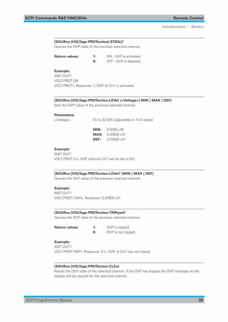
[SOURce:]VOLTage:PROTection[:STATe] {OFF | ON | 0 | 1} ........................................................ 34[SOURce:]VOLTage:PROTection[:STATe]? ................................................................................... 35[SOURce:]VOLTage:PROTection:LEVel {<Voltage>| MIN | MAX | DEF} ..................................... 35[SOURce:]VOLTage:PROTection:LEVel? [MIN | MAX | DEF] ....................................................... 35[SOURce:]VOLTage:PROTection:TRIPped? ................................................................................. 35[SOURce:]VOLTage:PROTection:CLEar ...................................................................................... 35[SOURce:]VOLTage:PROTection:MODE {MEASured | PROTected} ............................................ 36[SOURce:]VOLTage:PROTection:MODE? ................................................................................... 36
[SOURce:]VOLTage:PROTection[:STATe] {OFF | ON | 0 | 1} Activates or deactivates the OVP for the previous selected channel.
Parameters: ON | 1: OVP will be activated. OFF | 0: OVP will be deactivated.
*RST: OFF | 0
SCPI Commands R&S®HMC804x Remote Control
35
Introduction / Basics
SCPI Programmers Manual
[SOURce:]VOLTage:PROTection[:STATe]? Queries the OVP state of the previous selected channel.
Return values: 1: ON - OVP is activated. 0: OFF - OVP is disabled.
Example:INST OUT1VOLT:PROT ONVOLT:PROT?, Response: 1; OVP of CH1 is activated
[SOURce:]VOLTage:PROTection:LEVel {<Voltage>| MIN | MAX | DEF} Sets the OVP value of the previous selected channel.
Parameters: <Voltage> 0V to 32.50V (adjustable in 1mV steps)
MIN: 0.000E+00 MAX: 3.2050E+01 DEF: 3.2050E+01
Example:INST OUT1VOLT:PROT 5 (= OVP channel CH1 will be set to 5V)
[SOURce:]VOLTage:PROTection:LEVel? [MIN | MAX | DEF] Queries the OVP value of the previous selected channel.
Example:INST OUT1VOLT:PROT? MAX, Response: 3.2050E+01
[SOURce:]VOLTage:PROTection:TRIPped? Queries the OVP state of the previous selected channel.
Return values 1: OVP is tripped. 0: OVP is not tripped.
Example:INST OUT1VOLT:PROT:TRIP?, Response: 0 (= OVP of CH1 has not triped)
[SOURce:]VOLTage:PROTection:CLEar Resets the OVP state of the selected channel. If the OVP has tripped the OVP message on the display will be cleared for the selected channel.
SCPI Commands R&S®HMC804x Remote Control
36
Introduction / Basics
SCPI Programmers Manual
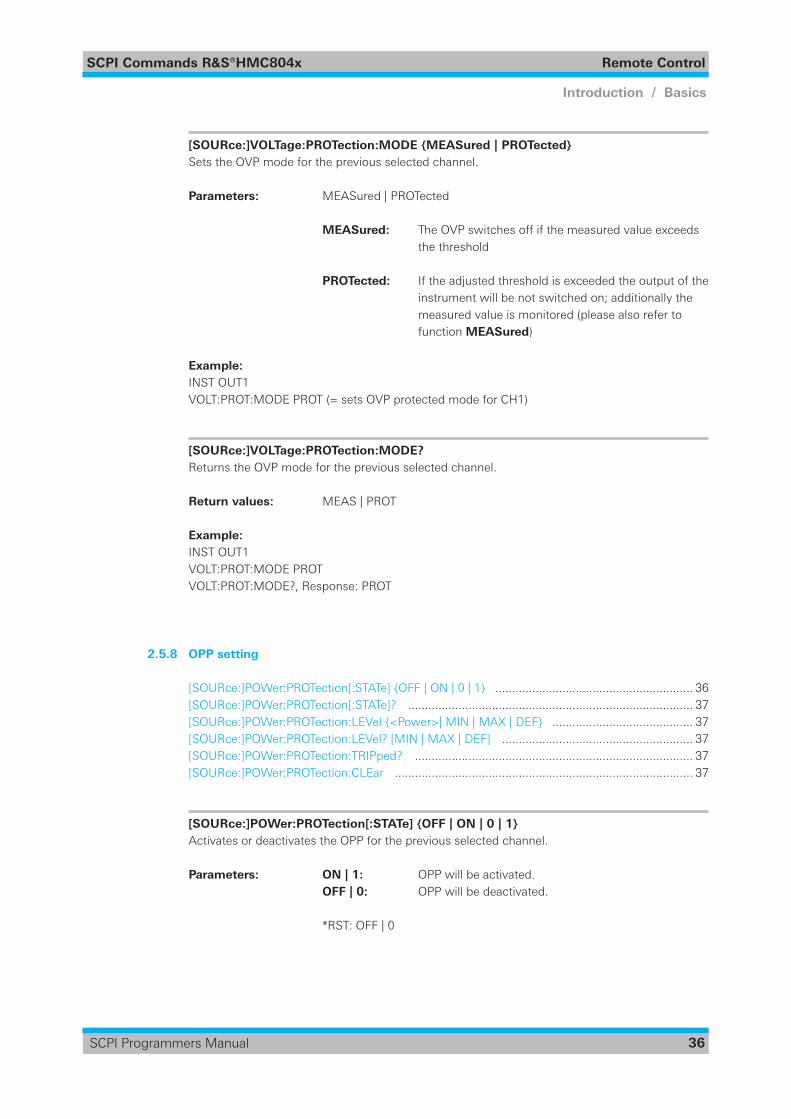
[SOURce:]VOLTage:PROTection:MODE {MEASured | PROTected} Sets the OVP mode for the previous selected channel.
Parameters: MEASured | PROTected
MEASured: The OVP switches off if the measured value exceeds the threshold
PROTected: If the adjusted threshold is exceeded the output of the instrument will be not switched on; additionally the measured value is monitored (please also refer to function MEASured)
Example:INST OUT1VOLT:PROT:MODE PROT (= sets OVP protected mode for CH1)
[SOURce:]VOLTage:PROTection:MODE? Returns the OVP mode for the previous selected channel.
Return values: MEAS | PROT
Example:INST OUT1VOLT:PROT:MODE PROTVOLT:PROT:MODE?, Response: PROT
2.5.8 OPP setting
[SOURce:]POWer:PROTection[:STATe] {OFF | ON | 0 | 1} ........................................................... 36[SOURce:]POWer:PROTection[:STATe]? ..................................................................................... 37[SOURce:]POWer:PROTection:LEVel {<Power>| MIN | MAX | DEF} .......................................... 37[SOURce:]POWer:PROTection:LEVel? [MIN | MAX | DEF] ......................................................... 37[SOURce:]POWer:PROTection:TRIPped? ................................................................................... 37[SOURce:]POWer:PROTection:CLEar ......................................................................................... 37
[SOURce:]POWer:PROTection[:STATe] {OFF | ON | 0 | 1} Activates or deactivates the OPP for the previous selected channel.
Parameters: ON | 1: OPP will be activated. OFF | 0: OPP will be deactivated.
*RST: OFF | 0
SCPI Commands R&S®HMC804x Remote Control
37
Introduction / Basics
SCPI Programmers Manual
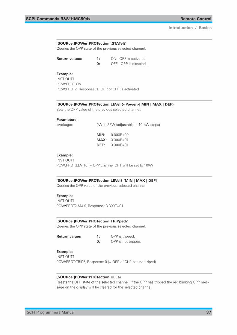
[SOURce:]POWer:PROTection[:STATe]? Queries the OPP state of the previous selected channel.
Return values: 1: ON - OPP is activated. 0: OFF - OPP is disabled.
Example:INST OUT1POW:PROT ONPOW:PROT?, Response: 1; OPP of CH1 is activated
[SOURce:]POWer:PROTection:LEVel {<Power>| MIN | MAX | DEF} Sets the OPP value of the previous selected channel.
Parameters: <Voltage> 0W to 33W (adjustable in 10mW steps)
MIN: 0.000E+00 MAX: 3.300E+01 DEF: 3.300E+01
Example:INST OUT1POW:PROT:LEV 10 (= OPP channel CH1 will be set to 10W)
[SOURce:]POWer:PROTection:LEVel? [MIN | MAX | DEF] Queries the OPP value of the previous selected channel.
Example:INST OUT1POW:PROT? MAX, Response: 3.300E+01
[SOURce:]POWer:PROTection:TRIPped? Queries the OPP state of the previous selected channel.
Return values 1: OPP is tripped. 0: OPP is not tripped.
Example:INST OUT1POW:PROT:TRIP?, Response: 0 (= OPP of CH1 has not triped)
[SOURce:]POWer:PROTection:CLEar Resets the OPP state of the selected channel. If the OPP has tripped the red blinking OPP mes-sage on the display will be cleared for the selected channel.
SCPI Commands R&S®HMC804x Remote Control
38
Introduction / Basics
SCPI Programmers Manual
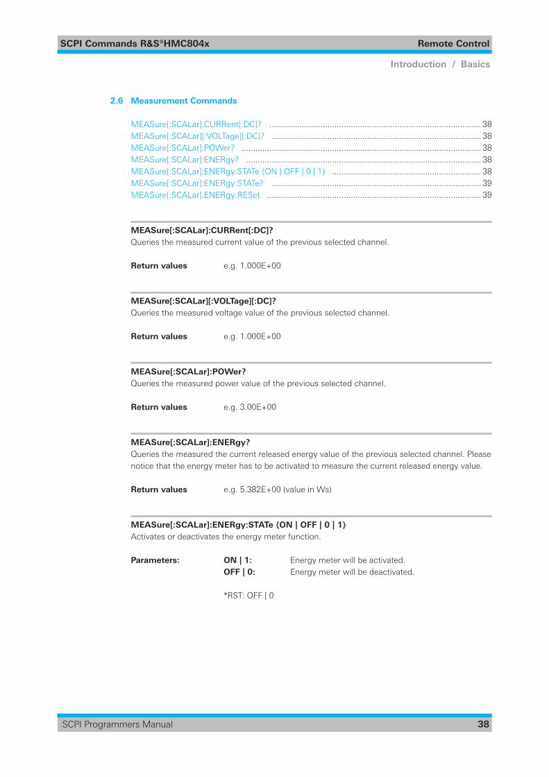
2.6 Measurement Commands
MEASure[:SCALar]:CURRent[:DC]? ........................................................................................... 38MEASure[:SCALar][:VOLTage][:DC]? .......................................................................................... 38MEASure[:SCALar]:POWer? ....................................................................................................... 38MEASure[:SCALar]:ENERgy? ..................................................................................................... 38MEASure[:SCALar]:ENERgy:STATe {ON | OFF | 0 | 1} ................................................................ 38MEASure[:SCALar]:ENERgy:STATe? .......................................................................................... 39MEASure[:SCALar]:ENERgy:RESet ............................................................................................ 39
MEASure[:SCALar]:CURRent[:DC]? Queries the measured current value of the previous selected channel.
Return values e.g. 1.000E+00
MEASure[:SCALar][:VOLTage][:DC]? Queries the measured voltage value of the previous selected channel.
Return values e.g. 1.000E+00
MEASure[:SCALar]:POWer? Queries the measured power value of the previous selected channel.
Return values e.g. 3.00E+00
MEASure[:SCALar]:ENERgy? Queries the measured the current released energy value of the previous selected channel. Please notice that the energy meter has to be activated to measure the current released energy value.
Return values e.g. 5.382E+00 (value in Ws)
MEASure[:SCALar]:ENERgy:STATe {ON | OFF | 0 | 1} Activates or deactivates the energy meter function.
Parameters: ON | 1: Energy meter will be activated. OFF | 0: Energy meter will be deactivated.
*RST: OFF | 0
SCPI Commands R&S®HMC804x Remote Control
39
Introduction / Basics
SCPI Programmers Manual
MEASure[:SCALar]:ENERgy:STATe? Queries the energy meter state of the the previous selected channel.
Return values: 1: ON - Energy meter is activated. 0: OFF - Energy meter is disabled.Example:INST OUT1MEAS:ENER:STAT ONMEAS:ENER:STAT?, Response: 1; Energy meter of CH1 is activated
MEASure[:SCALar]:ENERgy:RESet Resets the energy meter value of the previous selected channel.
Usage: Setting only
2.7 Arbitrary commands
ARBitrary[:STATe] {ON | OFF | 0 | 1} ........................................................................................... 39ARBitrary[:STATe]? ...................................................................................................................... 40ARBitrary:DATA <Data> ............................................................................................................. 40ARBitrary:DATA? ........................................................................................................................ 40ARBitrary:REPetitions <Repetitions> ......................................................................................... 40ARBitrary:REPetitions? ............................................................................................................... 41ARBitrary:ENDPoint <Endpoint> ............................................................................................... 41ARBitrary:ENDPoint? .................................................................................................................. 41ARBitrary:BEHavior:END {OFF | HOLD} ..................................................................................... 41ARBitrary:BEHavior:END? .......................................................................................................... 41ARBitrary:CLEar ......................................................................................................................... 42ARBitrary:TRIGgered[:STATe] {ON | OFF | 0 | 1} ......................................................................... 42ARBitrary:TRIGgered[:STATe]? .................................................................................................... 42ARBitrary:TRIGgered:MODE {SINGle | RUN} ............................................................................. 42ARBitrary:TRIGgered:MODE? .................................................................................................... 42ARBitrary:FNAMe {<“File_Name“>},[{INT | EXT | DEF}] ........................................................... 43ARBitrary:FNAMe? ..................................................................................................................... 43ARBitrary:SAVE .......................................................................................................................... 43ARBitrary:LOAD .......................................................................................................................... 43
ARBitrary[:STATe] {ON | OFF | 0 | 1} Activates or deactivates the arbitrary function for the previous selected channel.
Parameters: ON | 1: Arbitrary function will be activated. OFF | 0: Arbitrary function will be deactivated.
*RST: OFF | 0
SCPI Commands R&S®HMC804x Remote Control
40
Introduction / Basics
SCPI Programmers Manual
ARBitrary[:STATe]? Queries the arbitrary function state of the the previous selected channel.
Return values: 1: ON - Arbitrary function is activated. 0: OFF - Arbitrary function is disabled.
Example:INST OUT1ARB ONARB?, Response: 1; Arbitrary function of CH1 is activated
ARBitrary:DATA <Data> Definesthearbitrarypointsforthepreviousselectedchannel.Max.512arbitrarypointscanbedefined.Thedwelltimebetween2arbitrarypointsisspecifiedfrom10msto10min..
Parameters: <Data> voltage1,current1,time1,interpolation mode1,voltage2,current2, ... Voltage and current setting depending on the instrument type.
Interpolation mode 1: Y - Interpolation mode activated. 0: N - Interpolation mode disabled.
Example: INST OUT1ARB:DATA 10,1,0.5,0Definesonearbitrarypointwith:Voltage1 = 10VCurrent1 = 1ATime1 = 500msInterpolation mode = 0 (disabled)
ARBitrary:DATA? Queriesthedefinedarbitrarypointsforthepreviousselectedchannel.
Return values: e.g. 10.000,1.000,0.50,1
ARBitrary:REPetitions <Repetitions> Definestherepetitionrateofthedefinedarbitrarywaveformforthepreviousselectedchannel.Up to 255 repetitions are possible. If the repetition rate „0“ is selected the arbitrary waveform of thepreviousselectedchannelwillberepeatedinfinitely.
Parameters: 0 to 255 repetitions
Example: ARB:REP 10
SCPI Commands R&S®HMC804x Remote Control
41
Introduction / Basics
SCPI Programmers Manual
ARBitrary:REPetitions? Queriesthedefinedrepetitionrateofthepreviousselectedchannel.
Return values: 0 to 255
Example:INST OUT1ARB:REP 10ARB:REP?, Response: 10; the repetition rate of the CH1 arbitrary waveform is 10
ARBitrary:ENDPoint <Endpoint> Definesthearbitrarywaveformendpointoftheselectedchannel.Max.512arbitrarypointscanbedefined.
Parameters:<Endpoint> 1 to 512 arbitrary points
ARBitrary:ENDPoint? Queriesthedefinedarbitrarywaveformendpointoftheselectedchannel.
Return values: 0 to 512
Example:INST OUT1ARB:ENDP 30ARB:ENDP?, Response: 30; the arbitrary waveform of channel CH1 will be repeated 30 times
ARBitrary:BEHavior:END {OFF | HOLD} Definesthearbitraryendpointbehavior,whenarbitraryfunctionisfinished.
Parameters:<Endbehavior> OFF | HOLD
OFF: Ifthearbitraryfunctionisfinished,therespectivechannelwill be deactivated automatically. HOLD: Ifthearbitraryfunctionisfinished,thelastarbitrarypointof theuser-definedarbitrarylistwillbeheld.
*RST: OFF
ARBitrary:BEHavior:END? Queries the arbitrary endpoint behavior.
Return values: OFF | HOLD
SCPI Commands R&S®HMC804x Remote Control
42
Introduction / Basics
SCPI Programmers Manual
ARBitrary:CLEar Clearsthepreviousdefinedarbitrarywaveformdatafortheselectedchannel.
ARBitrary:TRIGgered[:STATe] {ON | OFF | 0 | 1} Activates or deactivates the trigger input on the rear connector (terminal block) for arbitrary functionality.
Parameters: ON | 1: Trigger input will be activated. OFF | 0: Trigger input will be deactivated.
*RST: OFF | 0
ARBitrary:TRIGgered[:STATe]? Queries the trigger input state of the the previous selected channel.
Return values: 1: ON - Trigger input is activated. 0: OFF - Trigger input is disabled.Example:INST OUT1ARB:TRIG ONARB:TRIG?, Response: 1; Trigger input on the rear connector is activated for CH1 arbitrary wave-form
ARBitrary:TRIGgered:MODE {SINGle | RUN} Selects the arbitrary trigger mode of the previous selected channel.
Parameters: SINGle | RUN
RUN A trigger event starts the whole arbitrary sequence (with all repititions). SING A trigger event starts only one arbitrary sequence.
ARBitrary:TRIGgered:MODE? Queries the arbitrary trigger mode of the previous selected channel.
Return values: RUN | SING
SCPI Commands R&S®HMC804x Remote Control
43
Introduction / Basics
SCPI Programmers Manual
ARBitrary:FNAMe {<“File_Name“>},[{INT | EXT | DEF}] Definesthefilenameandstoragelocationforthearbitraryfunction.
Parameters:<File_Name> e.g. “ARB01.CSV“,INT
INT: Internal memory EXT: USB stick DEF: Internal memory
ARBitrary:FNAMe? Queriesthefilenameandstoragelocationforthearbitraryfunction.
Return values: e.g. „ARB01.CSV“, INT
INT: Internal memory EXT: USB stick DEF: Internal memory
ARBitrary:SAVE Storesthepreviousdefinedarbitrarypointsoftheselectedchanneltotheselectedmemorywiththedefinedfilename.
Example:INST OUT1ARB:DATA 10,1,0.5,0ARB:REP 10ARB:FNAM „ARB03.CSV“,INTARB:SAVE
ARBitrary:LOAD Loads the stored arbitrary waveform of the previous selected channel and memory.
2.8 Advanced operating functions
2.8.1 Analog In
[SOURce:]VOLTage:AINPut[:STATe] {OFF | ON | 0 | 1} ............................................................... 44[SOURce:]VOLTage:AINPut[:STATe]? .......................................................................................... 44[SOURce:]VOLTage:AINPut:INPut {VOLTage | CURRent} .......................................................... 44[SOURce:]VOLTage:AINPut:INPut? ............................................................................................ 44[SOURce:]VOLTage:AINPut:MODE {LINear | STEP} ................................................................... 44[SOURce:]VOLTage:AINPut:MODE? ........................................................................................... 44[SOURce:]VOLTage:AINPut:THReshold {<Threshold>| MIN | MAX | DEF} ................................ 45[SOURce:]VOLTage:AINPut:THReshold? .................................................................................... 45
SCPI Commands R&S®HMC804x Remote Control
44
Introduction / Basics
SCPI Programmers Manual
[SOURce:]VOLTage:AINPut[:STATe] {OFF | ON | 0 | 1} Activates or deactivates the Analog In function for the previous selected channel.
Parameters: ON | 1: Analog In function will be activated. OFF | 0: Analog In function will be deactivated.
*RST: OFF | 0
[SOURce:]VOLTage:AINPut[:STATe]? Queries the Analog In function state of the the previous selected channel.
Return values: 1: ON - Analog In function is activated. 0: OFF - Analog In function is disabled.Example:INST OUT1VOLT:AINP ONVOLT:AINP?, Response: 1; Analog In function of CH1 is activated
[SOURce:]VOLTage:AINPut:INPut {VOLTage | CURRent} Selects the input unit of the Analog In connector (terminal block) on the rear panel.
Parameters: VOLTage | CURRent
[SOURce:]VOLTage:AINPut:INPut? Queries the input unit of the Analog In connector (terminal block) on the rear panel.
Return values: VOLT | CURR
[SOURce:]VOLTage:AINPut:MODE {LINear | STEP} Selects the mode of the Analog In connector (terminal block) on the rear panel.
Parameters: LINear | STEP
LINear: Output voltage linear to the input voltage. STEP: Reference value or zero depending on threshold.
[SOURce:]VOLTage:AINPut:MODE? Queries the mode of the Analog In connector (terminal block) on the rear panel.
Return values: LIN | STEP
SCPI Commands R&S®HMC804x Remote Control
45
Introduction / Basics
SCPI Programmers Manual
[SOURce:]VOLTage:AINPut:THReshold {<Threshold>| MIN | MAX | DEF} Sets the threshold for the Analog In mode STEP.
Parameters:<Threshold> 0V to 10V (adjustable in 100mV steps)
MIN: 0.0E+00 MAX: 1.00E+01 DEF: 1.0E+00
[SOURce:]VOLTage:AINPut:THReshold? Queries the threshold of the Analog In mode STEP.
Return values: e.g. 5.0E+00
Example:INST OUT 1VOLT:AINP ONVOLT:AINP:MODE STEPVOLT:AINP:THR 5VOLT:AINP:THR?, Response: 5; the threshold of the Analog In mode STEP is set to 5V
2.8.2 EasyRamp
[SOURce:]VOLTage:RAMP[:STATe] {OFF | ON | 0 | 1} ................................................................ 45[SOURce:]VOLTage:RAMP[:STATe]? ........................................................................................... 45[SOURce:]VOLTage:RAMP:DURation {<Duration>| MIN | MAX | DEF} ..................................... 46[SOURce:]VOLTage:RAMP:DURation? ....................................................................................... 46
[SOURce:]VOLTage:RAMP[:STATe] {OFF | ON | 0 | 1} Activates or deactivates the EasyRamp function for the previous selected channel.
Parameters: ON | 1: EasyRamp function will be activated. OFF | 0: EasyRamp function will be deactivated.
*RST: OFF | 0
[SOURce:]VOLTage:RAMP[:STATe]? Queries the EasyRamp function state of the the previous selected channel.
Return values: 1: ON - EasyRamp function is activated. 0: OFF - EasyRamp function is disabled.
Example:INST OUT1VOLT:RAMP ONVOLT:RAMP?, Response: 1; EasyRamp function of CH1 is activated
SCPI Commands R&S®HMC804x Remote Control
46
Introduction / Basics
SCPI Programmers Manual
[SOURce:]VOLTage:RAMP:DURation {<Duration>| MIN | MAX | DEF} Sets the duration of the voltage ramp.
Parameters:<Duration> 10ms to 10s
MIN: 1.00E-02 MAX: 1.000E+01 DEF: 1.00E-02
[SOURce:]VOLTage:RAMP:DURation? Queries the duration of the voltage ramp.
Return values: e.g. 4.00E+00
2.8.3 Sequencing
SEQuence[:STATe] {ON | OFF | 0| 1} .......................................................................................... 46SEQuence[:STATe]? .................................................................................................................... 46SEQuence:CHANnel[:STATe] {ON | OFF | 0 | 1} .......................................................................... 47SEQuence:CHANnel[:STATe]? .................................................................................................... 47SEQuence:DELay {<Delay>| MIN | MAX} .................................................................................. 47SEQuence:DELay? ..................................................................................................................... 47SEQuence:TRIGgered {ON | OFF | 0 | 1} .................................................................................... 47SEQuence:TRIGgered? ............................................................................................................... 48
SEQuence[:STATe] {ON | OFF | 0| 1} Activates or deactivates the power sequencing function.
Parameters: ON | 1: Sequencing function will be activated. OFF | 0: Sequencing function will be deactivated.
*RST: OFF | 0
SEQuence[:STATe]? Queries the power sequencing function state.
Return values: 1: ON - Sequencing function is activated. 0: OFF - Sequencing function is disabled.
Example:SEQ ONSEQ?, Response: 1; Sequencing function is activated
SCPI Commands R&S®HMC804x Remote Control
47
Introduction / Basics
SCPI Programmers Manual
SEQuence:CHANnel[:STATe] {ON | OFF | 0 | 1} Activates or deactivates the power sequencing delay of the previous selected channel.
Parameters: ON | 1: Sequencing delay will be activated. OFF | 0: Sequencing delay will be deactivated.
*RST: OFF | 0
SEQuence:CHANnel[:STATe]? Queries the power sequencing dely of the previous selected channel.
Return values: 1: ON - Sequencing delay is activated. 0: OFF - Sequencing delay is disabled.
Example:INST OUT1SEQ:CHAN ONSEQ:CHAN?, Response: 1; Sequencing delay for channel CH1 is activated
SEQuence:DELay {<Delay>| MIN | MAX} Definesthepowersequencingdelayofthepreviousselectedchannel.
Parameters:<Delay> 1ms to 60s
MIN: 1.000E-03 MAX: 6.0000E+01
SEQuence:DELay? Queries the power sequencing delay of the previous selected channel.
Return values: e.g. 2.000E+00
SEQuence:TRIGgered {ON | OFF | 0 | 1} Activates or deactivates the power sequencing trigger function of the previous selected channel.
Parameters: ON | 1: Trigger function will be activated. OFF | 0: Trigger function will be deactivated.
*RST: OFF | 0
SCPI Commands R&S®HMC804x Remote Control
48
Introduction / Basics
SCPI Programmers Manual
SEQuence:TRIGgered? Queries the state of the power sequencing trigger function.
Return values: 1: ON - Trigger function is activated. 0: OFF - Trigger function is disabled.
Example:SEQ:TRIG ONSEQ:TRIG?, Response: 1; Trigger function is activated
2.9 Data and File Management
[DATA]LOG[:STATe] {ON | OFF | 0 | 1} ........................................................................................ 49[DATA:]LOG[:STATe]? .................................................................................................................. 49[DATA:]LOG:CHANnel[:STATe] {ON | OFF | 0 | 1} ....................................................................... 49[DATA:]LOG:CHANnel[:STATe]? .................................................................................................. 49[DATA:]LOG:FNAMe {<“File_Name“>},[{INT | EXT | DEF}] ........................................................ 49[DATA:]LOG:FNAMe? ................................................................................................................. 50[DATA:]LOG:FORMat {CSV | TXT} .............................................................................................. 50[DATA:]LOG:FORMat? ................................................................................................................ 50[DATA:]LOG:MODE {UNLimited | COUNt | TIME} ...................................................................... 50[DATA:]LOG:MODE? ................................................................................................................... 50[DATA:]LOG:TIME <Time in sec> ............................................................................................... 50[DATA:]LOG:TIME? ..................................................................................................................... 51[DATA:]LOG:COUNt <No of samples> ....................................................................................... 51[DATA:]LOG:COUNt? .................................................................................................................. 51[DATA:]LOG:INTerval <Interval in seconds> ............................................................................... 51[DATA:]LOG:INTerval? ................................................................................................................. 51[DATA:]LOG:TRIGgered {ON | OFF | 0 | 1} .................................................................................. 51[DATA:]LOG:TRIGgered? ............................................................................................................. 51DATA:DATA? {<“Filename“>},[{INT | EXT | DEF}] ...................................................................... 52DATA:DELete {<“Filename“>},[{INT | EXT | DEF }] .................................................................... 52DATA:POINts? {<“Filename“>},[{INT | EXT | DEF }] ................................................................... 53DATA:LIST? [{INT | EXT | DEF}] .................................................................................................. 53HCOPy:DATA? ............................................................................................................................ 53HCOPy:FORMat {BMP | PNG} ................................................................................................... 53HCOPy:FORMat? ........................................................................................................................ 54HCOPy:SIZE:X? .......................................................................................................................... 54HCOPy:SIZE:Y? .......................................................................................................................... 54*SAV {0 | 1 | 2 | 3 | 4 | 5 | 6 | 7 | 8 | 9} ......................................................................................... 54*RCL {0 | 1 | 2 | 3 | 4 | 5 | 6 | 7 | 8 | 9} ......................................................................................... 54
SCPI Commands R&S®HMC804x Remote Control
49
Introduction / Basics
SCPI Programmers Manual
[DATA]LOG[:STATe] {ON | OFF | 0 | 1} Turns the data logging function on or off.
Parameters: ON / 1: Data logging function will be activated. OFF / 0: Data logging function will be deactivated.
*RST: OFF | 0
[DATA:]LOG[:STATe]? Queries the state of the data logging function.
Return values: 1: ON - Data logging function is activated. 0: OFF - Data logging function is disabled.
[DATA:]LOG:CHANnel[:STATe] {ON | OFF | 0 | 1} Turns the data logging function for the previous selected channel on or off.
Parameters: ON / 1: Data logging function for the previous selected channel will be activated. OFF / 0: Data logging function for the previous selected channel will be deactivated.
[DATA:]LOG:CHANnel[:STATe]? Queries the state of the data logging function.
Return values: 1: ON - Data logging function for the previous selected channel is activated. 0: OFF - Data logging function for the previous selected channel is disabled.
[DATA:]LOG:FNAMe {<“File_Name“>},[{INT | EXT | DEF}] Definesthefilenameandstoragelocationfortheloggingfunction.
Parameters:<File_Name> e.g. “Test01.CSV“,INT
INT: Internal memory EXT: USB stick DEF: Internal memory
SCPI Commands R&S®HMC804x Remote Control
50
Introduction / Basics
SCPI Programmers Manual
[DATA:]LOG:FNAMe? Returnsthefilenameandstoragelocationfortheloggingfunction.
Return values: e.g. “/INT/DATA/Test01.CSV“
INT: Internal memory EXT: USB stick DEF: Internal memory
[DATA:]LOG:FORMat {CSV | TXT} Definesthedataloggingfileformat.
Parameters: CSV: Comma separated values TXT: Textfile
*RST: CSV
[DATA:]LOG:FORMat? Returnsthedataloggingfileformat.
Return values: CSV | TXT
[DATA:]LOG:MODE {UNLimited | COUNt | TIME} Selects the data logging mode.
Parameters: UNLimited: Infinitedatacapture. COUNt: Number of measurement values to be captured. TIME: Duration of the measurement values capture.
*RST: UNL
[DATA:]LOG:MODE? Queries the data logging mode.
Return values: UNL | COUN | TIME
[DATA:]LOG:TIME <Time in sec> Sets the data logging time.
Parameters:<Time in seconds> Depending on instrument settings.
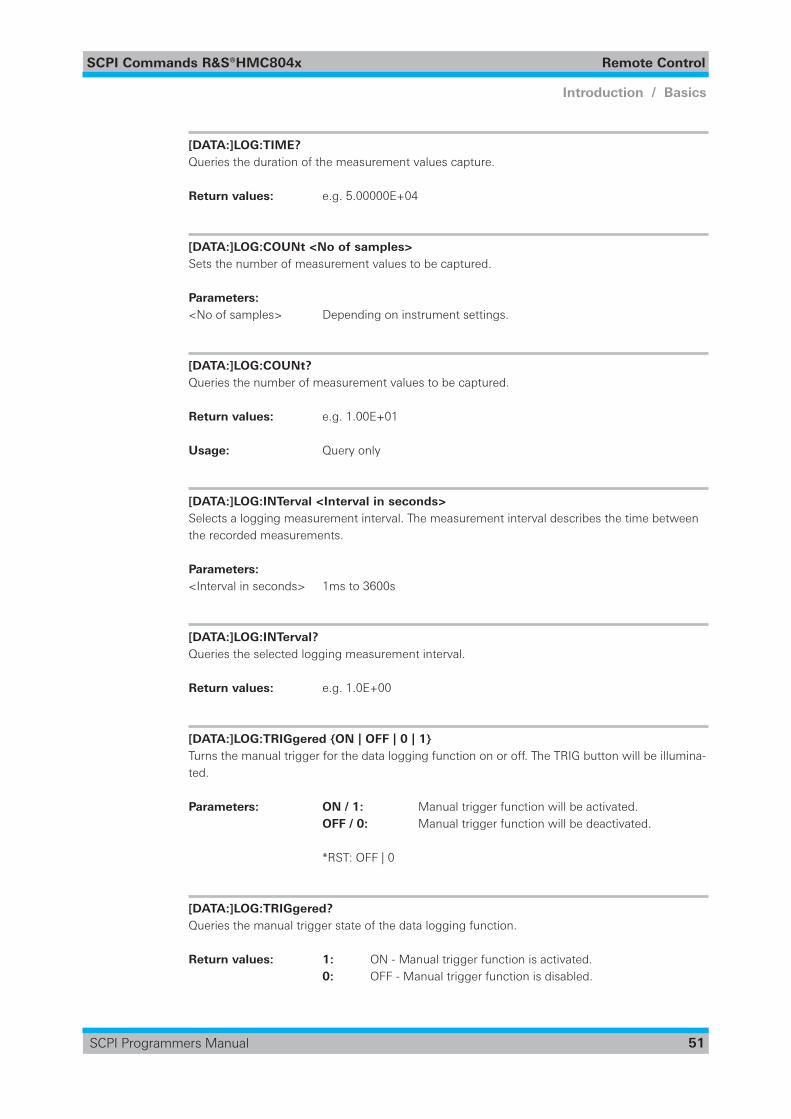
SCPI Commands R&S®HMC804x Remote Control
51
Introduction / Basics
SCPI Programmers Manual
[DATA:]LOG:TIME? Queries the duration of the measurement values capture.
Return values: e.g. 5.00000E+04
[DATA:]LOG:COUNt <No of samples> Sets the number of measurement values to be captured.
Parameters:<No of samples> Depending on instrument settings.
[DATA:]LOG:COUNt? Queries the number of measurement values to be captured.
Return values: e.g. 1.00E+01
Usage: Query only
[DATA:]LOG:INTerval <Interval in seconds> Selects a logging measurement interval. The measurement interval describes the time between the recorded measurements.
Parameters:<Interval in seconds> 1ms to 3600s
[DATA:]LOG:INTerval? Queries the selected logging measurement interval.
Return values: e.g. 1.0E+00
[DATA:]LOG:TRIGgered {ON | OFF | 0 | 1} Turns the manual trigger for the data logging function on or off. The TRIG button will be illumina-ted.
Parameters: ON / 1: Manual trigger function will be activated. OFF / 0: Manual trigger function will be deactivated.
*RST: OFF | 0
[DATA:]LOG:TRIGgered? Queries the manual trigger state of the data logging function.
Return values: 1: ON - Manual trigger function is activated. 0: OFF - Manual trigger function is disabled.
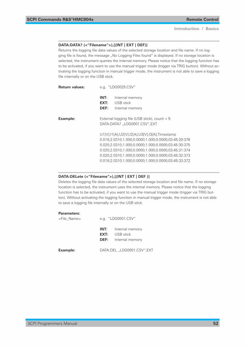
SCPI Commands R&S®HMC804x Remote Control
52
Introduction / Basics
SCPI Programmers Manual
DATA:DATA? {<“Filename“>},[{INT | EXT | DEF}] Returnstheloggingfiledatavaluesoftheselectedstoragelocationandfilename.Ifnolog-gingfileisfound,themessage„NoLoggingFilesfound“isdisplayed.Ifnostoragelocationisselected, the instrument queries the internal memory. Please notice that the logging function has to be activated, if you want to use the manual trigger mode (trigger via TRIG button). Without ac-tivating the logging function in manual trigger mode, the instrument is not able to save a logging fileinternallyorontheUSBstick.
Return values: e.g. “LOG0029.CSV“
INT: Internal memory EXT: USB stick DEF: Internal memory
Example: Externalloggingfile(USBstick),count=5 DATA:DATA? „LOG0001.CSV“,EXT
U1[V];I1[A];U2[V];I2[A];U3[V];I3[A];Timestamp 0.019;2.0310;1.000;0.0000;1.000;0.0000;03:45:29:376 0.020;2.0310;1.000;0.0000;1.000;0.0000;03:45:30:375 0.020;2.0310;1.000;0.0000;1.000;0.0000;03:45:31:374 0.020;2.0310;1.000;0.0000;1.000;0.0000;03:45:32:373 0.019;2.0310;1.000;0.0000;1.000;0.0000;03:45:33:372
DATA:DELete {<“Filename“>},[{INT | EXT | DEF }] Deletestheloggingfiledatavaluesoftheselectedstoragelocationandfilename.Ifnostoragelocation is selected, the instrument uses the internal memory. Please notice that the logging function has to be activated, if you want to use the manual trigger mode (trigger via TRIG but-ton). Without activating the logging function in manual trigger mode, the instrument is not able tosavealoggingfileinternallyorontheUSBstick.
Parameters:<File_Name> e.g. “LOG0001.CSV“
INT: Internal memory EXT: USB stick DEF: Internal memory
Example: DATA:DEL „LOG0001.CSV“,EXT
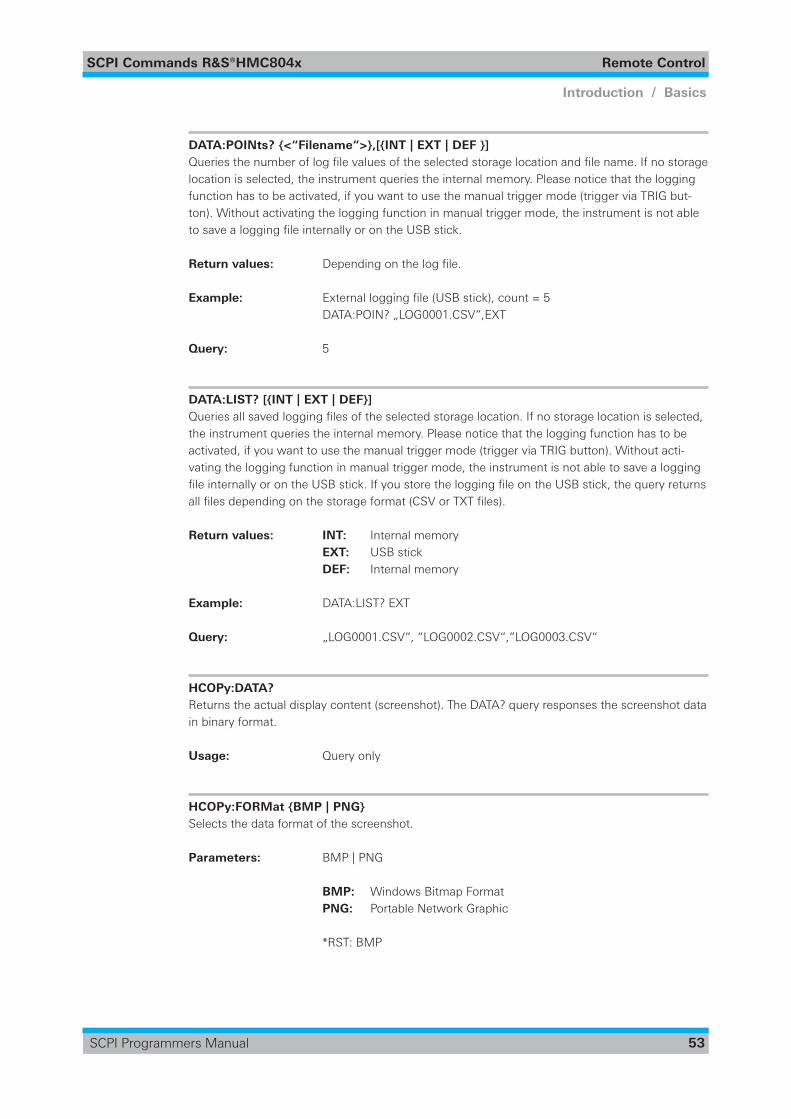
SCPI Commands R&S®HMC804x Remote Control
53
Introduction / Basics
SCPI Programmers Manual
DATA:POINts? {<“Filename“>},[{INT | EXT | DEF }] Queriesthenumberoflogfilevaluesoftheselectedstoragelocationandfilename.Ifnostoragelocation is selected, the instrument queries the internal memory. Please notice that the logging function has to be activated, if you want to use the manual trigger mode (trigger via TRIG but-ton). Without activating the logging function in manual trigger mode, the instrument is not able tosavealoggingfileinternallyorontheUSBstick.
Return values: Dependingonthelogfile.
Example: Externalloggingfile(USBstick),count=5 DATA:POIN? „LOG0001.CSV“,EXT
Query: 5
DATA:LIST? [{INT | EXT | DEF}] Queriesallsavedloggingfilesoftheselectedstoragelocation.Ifnostoragelocationisselected,the instrument queries the internal memory. Please notice that the logging function has to be activated, if you want to use the manual trigger mode (trigger via TRIG button). Without acti-vating the logging function in manual trigger mode, the instrument is not able to save a logging fileinternallyorontheUSBstick.IfyoustoretheloggingfileontheUSBstick,thequeryreturnsallfilesdependingonthestorageformat(CSVorTXTfiles).
Return values: INT: Internal memory EXT: USB stick DEF: Internal memory
Example: DATA:LIST? EXT
Query: „LOG0001.CSV“, “LOG0002.CSV“,“LOG0003.CSV“
HCOPy:DATA? Returns the actual display content (screenshot). The DATA? query responses the screenshot data in binary format.
Usage: Query only
HCOPy:FORMat {BMP | PNG} Selects the data format of the screenshot.
Parameters: BMP | PNG
BMP: Windows Bitmap Format PNG: Portable Network Graphic
*RST: BMP
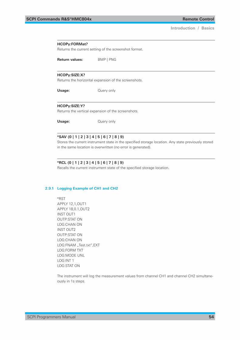
SCPI Commands R&S®HMC804x Remote Control
54
Introduction / Basics
SCPI Programmers Manual
HCOPy:FORMat? Returns the current setting of the screenshot format.
Return values: BMP | PNG
HCOPy:SIZE:X? Returns the horizontal expansion of the screenshots.
Usage: Query only
HCOPy:SIZE:Y? Returns the vertical expansion of the screenshots.
Usage: Query only
*SAV {0 | 1 | 2 | 3 | 4 | 5 | 6 | 7 | 8 | 9} Storesthecurrentinstrumentstateinthespecifiedstoragelocation.Anystatepreviouslystoredin the same location is overwritten (no error is generated).
*RCL {0 | 1 | 2 | 3 | 4 | 5 | 6 | 7 | 8 | 9} Recallsthecurrentinstrumentstateofthespecifiedstoragelocation.
2.9.1 Logging Example of CH1 and CH2
*RST APPLY 12,1,OUT1 APPLY 18,0.1,OUT2 INST OUT1 OUTP:STAT ON LOG:CHAN ONINST OUT2 OUTP:STAT ON LOG:CHAN ONLOG:FNAM „Test.txt“,EXTLOG:FORM TXT LOG:MODE UNL LOG:INT 1LOG:STAT ON
The instrument will log the measurement values from channel CH1 and channel CH2 simultane-ously in 1s steps.
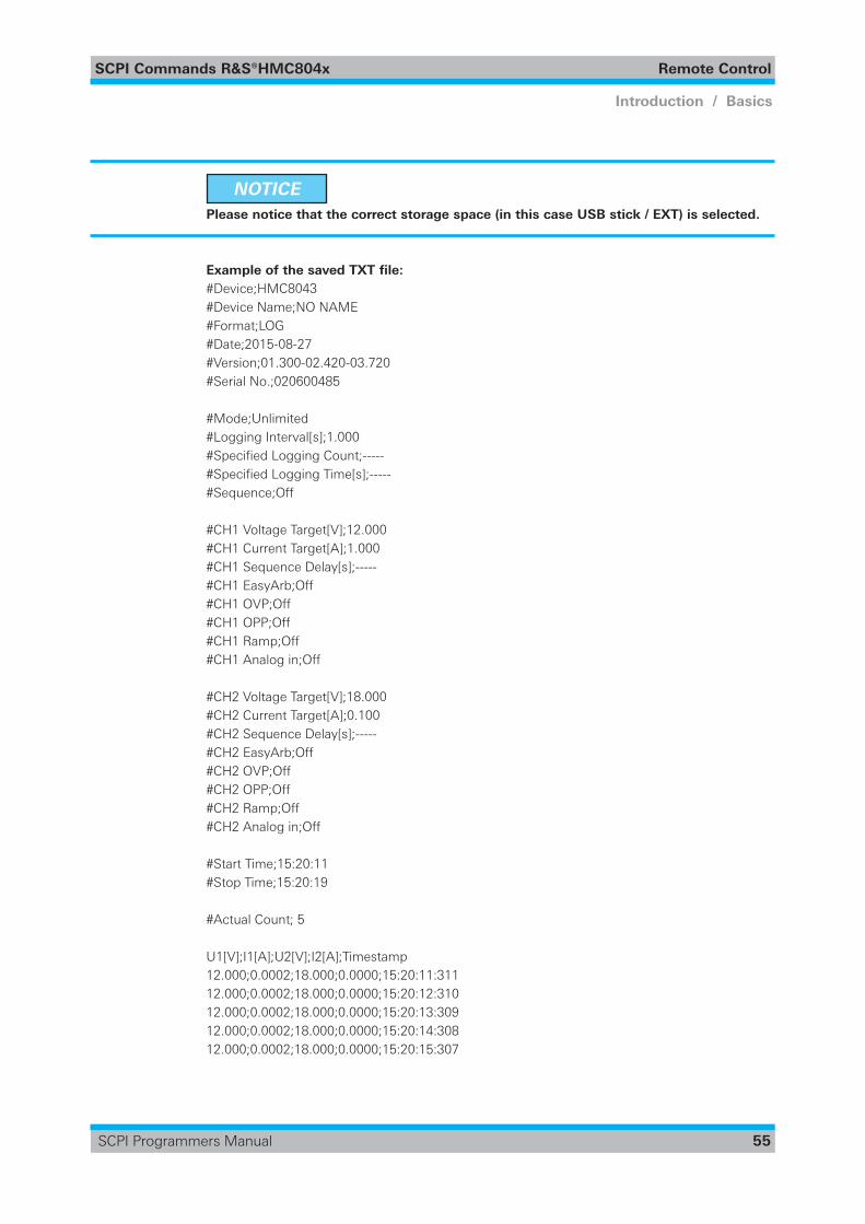
SCPI Commands R&S®HMC804x Remote Control
55
Introduction / Basics
SCPI Programmers Manual
NOTICE Please notice that the correct storage space (in this case USB stick / EXT) is selected.
Example of the saved TXT file:#Device;HMC8043#Device Name;NO NAME#Format;LOG#Date;2015-08-27#Version;01.300-02.420-03.720#Serial No.;020600485
#Mode;Unlimited#Logging Interval[s];1.000#SpecifiedLoggingCount;-----#SpecifiedLoggingTime[s];-----#Sequence;Off
#CH1 Voltage Target[V];12.000#CH1 Current Target[A];1.000#CH1 Sequence Delay[s];-----#CH1 EasyArb;Off#CH1 OVP;Off#CH1 OPP;Off#CH1 Ramp;Off#CH1 Analog in;Off
#CH2 Voltage Target[V];18.000#CH2 Current Target[A];0.100#CH2 Sequence Delay[s];-----#CH2 EasyArb;Off#CH2 OVP;Off#CH2 OPP;Off#CH2 Ramp;Off#CH2 Analog in;Off
#Start Time;15:20:11#Stop Time;15:20:19
#Actual Count; 5
U1[V];I1[A];U2[V];I2[A];Timestamp12.000;0.0002;18.000;0.0000;15:20:11:31112.000;0.0002;18.000;0.0000;15:20:12:31012.000;0.0002;18.000;0.0000;15:20:13:30912.000;0.0002;18.000;0.0000;15:20:14:30812.000;0.0002;18.000;0.0000;15:20:15:307
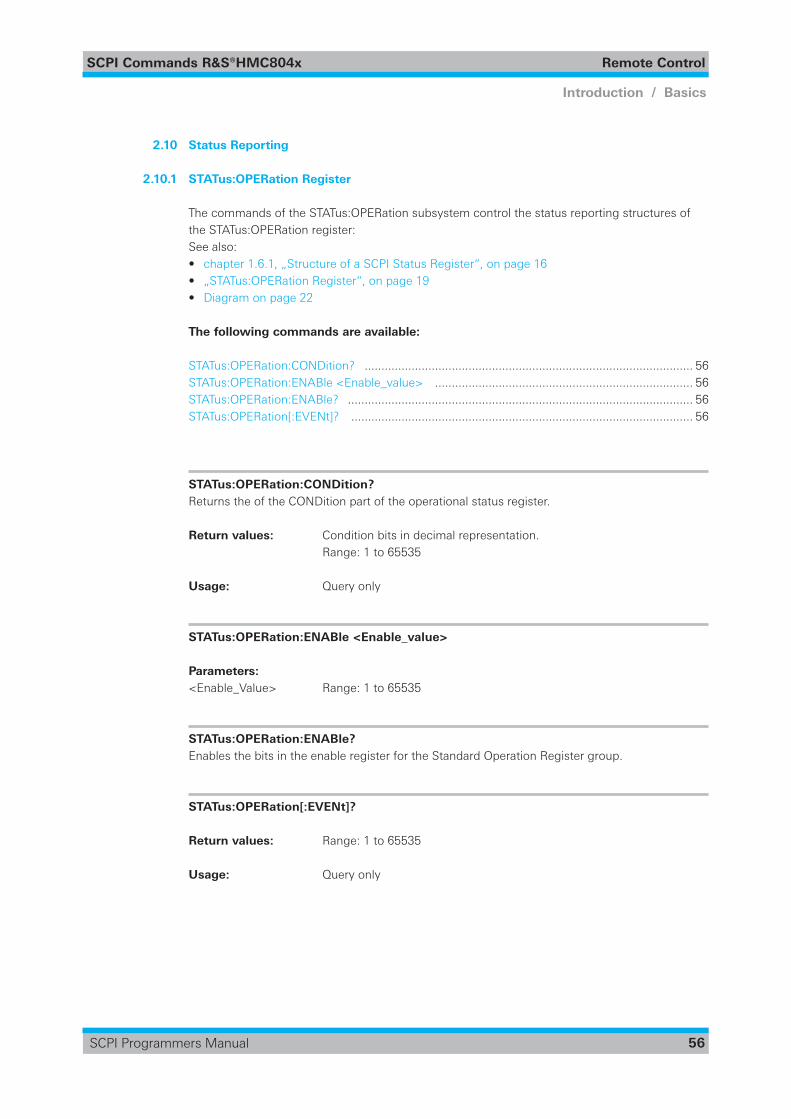
SCPI Commands R&S®HMC804x Remote Control
56
Introduction / Basics
SCPI Programmers Manual
2.10 Status Reporting
2.10.1 STATus:OPERation Register
The commands of the STATus:OPERation subsystem control the status reporting structures of the STATus:OPERation register: See also: • chapter 1.6.1, „Structure of a SCPI Status Register“, on page 16 • „STATus:OPERation Register“, on page 19• Diagram on page 22
The following commands are available:
STATus:OPERation:CONDition? .................................................................................................. 56STATus:OPERation:ENABle <Enable_value> ............................................................................. 56STATus:OPERation:ENABle? ....................................................................................................... 56STATus:OPERation[:EVENt]? ...................................................................................................... 56
STATus:OPERation:CONDition? Returns the of the CONDition part of the operational status register.
Return values: Condition bits in decimal representation. Range: 1 to 65535
Usage: Query only
STATus:OPERation:ENABle <Enable_value>
Parameters: <Enable_Value> Range: 1 to 65535
STATus:OPERation:ENABle? Enables the bits in the enable register for the Standard Operation Register group.
STATus:OPERation[:EVENt]?
Return values: Range: 1 to 65535
Usage: Query only
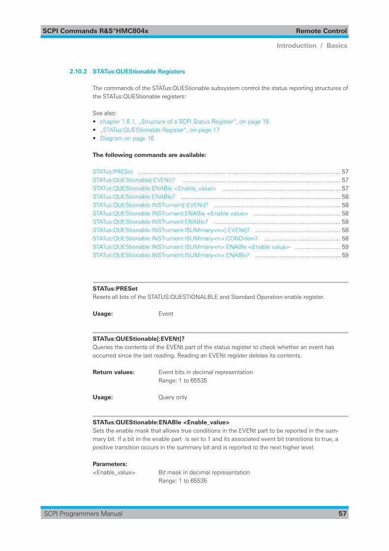
SCPI Commands R&S®HMC804x Remote Control
57
Introduction / Basics
SCPI Programmers Manual
2.10.2 STATus:QUEStionable Registers
The commands of the STATus:QUEStionable subsystem control the status reporting structures of the STATus:QUEStionable registers:
See also: • chapter 1.6.1, „Structure of a SCPI Status Register“, on page 15 • „STATus:QUEStionable Register“, on page 17• Diagram on page 16
The following commands are available:
STATus:PRESet ........................................................................................................................... 57STATus:QUEStionable[:EVENt]? ................................................................................................ 57STATus:QUEStionable:ENABle <Enable_value> ........................................................................ 57STATus:QUEStionable:ENABle? ................................................................................................. 58STATus:QUEStionable:INSTrument[:EVENt]? ............................................................................. 58STATus:QUEStionable:INSTrument:ENABle <Enable value> ..................................................... 58STATus:QUEStionable:INSTrument:ENABle? ............................................................................. 58STATus:QUEStionable:INSTrument:ISUMmary<n>[:EVENt]? .................................................... 58STATus:QUEStionable:INSTrument:ISUMmary<n>:CONDition? ............................................... 58STATus:QUEStionable:INSTrument:ISUMmary<n>:ENABle <Enable value> ............................ 59STATus:QUEStionable:INSTrument:ISUMmary<n>:ENABle? .................................................... 59
STATus:PRESet Resets all bits of the STATUS:QUESTIONALBLE and Standard Operation enable register.
Usage: Event
STATus:QUEStionable[:EVENt]? Queries the contents of the EVENt part of the status register to check whether an event has occurred since the last reading. Reading an EVENt register deletes its contents.
Return values: Event bits in decimal representation Range: 1 to 65535
Usage: Query only
STATus:QUEStionable:ENABle <Enable_value> Sets the enable mask that allows true conditions in the EVENt part to be reported in the sum-mary bit. If a bit in the enable part is set to 1 and its associated event bit transitions to true, a positive transition occurs in the summary bit and is reported to the next higher level.
Parameters: <Enable_value> Bit mask in decimal representation Range: 1 to 65535
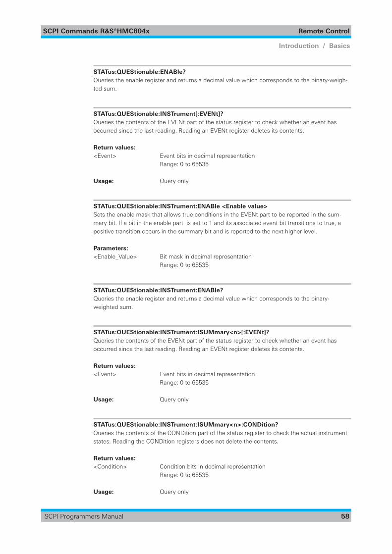
SCPI Commands R&S®HMC804x Remote Control
58
Introduction / Basics
SCPI Programmers Manual
STATus:QUEStionable:ENABle? Queries the enable register and returns a decimal value which corresponds to the binary-weigh-ted sum.
STATus:QUEStionable:INSTrument[:EVENt]? Queries the contents of the EVENt part of the status register to check whether an event has occurred since the last reading. Reading an EVENt register deletes its contents.
Return values: <Event> Event bits in decimal representation Range: 0 to 65535
Usage: Query only
STATus:QUEStionable:INSTrument:ENABle <Enable value> Sets the enable mask that allows true conditions in the EVENt part to be reported in the sum-mary bit. If a bit in the enable part is set to 1 and its associated event bit transitions to true, a positive transition occurs in the summary bit and is reported to the next higher level.
Parameters: <Enable_Value> Bit mask in decimal representation Range: 0 to 65535
STATus:QUEStionable:INSTrument:ENABle? Queries the enable register and returns a decimal value which corresponds to the binary-weighted sum.
STATus:QUEStionable:INSTrument:ISUMmary<n>[:EVENt]? Queries the contents of the EVENt part of the status register to check whether an event has occurred since the last reading. Reading an EVENt register deletes its contents.
Return values: <Event> Event bits in decimal representation Range: 0 to 65535
Usage: Query only
STATus:QUEStionable:INSTrument:ISUMmary<n>:CONDition? Queries the contents of the CONDition part of the status register to check the actual instrument states. Reading the CONDition registers does not delete the contents.
Return values: <Condition> Condition bits in decimal representation Range: 0 to 65535
Usage: Query only
SCPI Commands R&S®HMC804x Remote Control
59
Introduction / Basics
SCPI Programmers Manual
STATus:QUEStionable:INSTrument:ISUMmary<n>:ENABle <Enable value> Sets the enable mask that allows true conditions in the EVENt part to be reported in the sum-mary bit. If a bit in the enable part is set to 1 and its associated event bit transitions to true, a positive transition occurs in the summary bit and is reported to the next higher level.
Parameters: <Enable_Value> Bit mask in decimal representation Range: 0 to 65535
STATus:QUEStionable:INSTrument:ISUMmary<n>:ENABle? Queries the enable register and returns a decimal value which corresponds to the binary-weighted sum.
SCPI Commands R&S®HMC804x Remote Control
60
Introduction / Basics
SCPI Programmers Manual
3 SCPI Command Listin alphabetic order
APPLy? ....................................................................................................................................... 29APPLy {<Voltage>|DEF|MIN|MAX} [,{<Current>|DEF|MIN|MAX}][,{OUT1|OUT2|OUT3}] ........ 29ARBitrary:BEHavior:END? .......................................................................................................... 41ARBitrary:BEHavior:END {OFF | HOLD} ..................................................................................... 41ARBitrary:CLEar ......................................................................................................................... 42ARBitrary:DATA? ........................................................................................................................ 40ARBitrary:DATA <Data> ............................................................................................................. 40ARBitrary:ENDPoint? .................................................................................................................. 41ARBitrary:ENDPoint <Endpoint> ............................................................................................... 41ARBitrary:FNAMe? ..................................................................................................................... 43ARBitrary:FNAMe {<“File_Name“>},[{INT | EXT | DEF}] ........................................................... 43ARBitrary:LOAD .......................................................................................................................... 43ARBitrary:REPetitions? ............................................................................................................... 41ARBitrary:REPetitions <Repetitions> ......................................................................................... 40ARBitrary:SAVE .......................................................................................................................... 43ARBitrary[:STATe]? ...................................................................................................................... 40ARBitrary[:STATe] {ON | OFF | 0 | 1} ........................................................................................... 39ARBitrary:TRIGgered:MODE? .................................................................................................... 42ARBitrary:TRIGgered:MODE {SINGle | RUN} ............................................................................. 42ARBitrary:TRIGgered[:STATe]? .................................................................................................... 42ARBitrary:TRIGgered[:STATe] {ON | OFF | 0 | 1} ......................................................................... 42
*CLS ........................................................................................................................................... 19
DATA:DATA? {<“Filename“>},[{INT | EXT | DEF}] ...................................................................... 52DATA:DELete {<“Filename“>},[{INT | EXT | DEF }] .................................................................... 52DATA:LIST? [{INT | EXT | DEF}] .................................................................................................. 53[DATA:]LOG:CHANnel[:STATe]? .................................................................................................. 49[DATA:]LOG:CHANnel[:STATe] {ON | OFF | 0 | 1} ....................................................................... 49[DATA:]LOG:COUNt? .................................................................................................................. 51[DATA:]LOG:COUNt <No of samples> ....................................................................................... 51[DATA:]LOG:FNAMe? ................................................................................................................. 50[DATA:]LOG:FNAMe {<“File_Name“>},[{INT | EXT | DEF}] ........................................................ 49[DATA:]LOG:FORMat? ................................................................................................................ 50[DATA:]LOG:FORMat {CSV | TXT} .............................................................................................. 50[DATA:]LOG:INTerval? ................................................................................................................. 51[DATA:]LOG:INTerval <Interval in seconds> ............................................................................... 51[DATA:]LOG:MODE? ................................................................................................................... 50[DATA:]LOG:MODE {UNLimited | COUNt | TIME} ...................................................................... 50[DATA:]LOG[:STATe]? .................................................................................................................. 49[DATA]LOG[:STATe] {ON | OFF | 0 | 1} ........................................................................................ 49[DATA:]LOG:TIME? ..................................................................................................................... 51[DATA:]LOG:TIME <Time in sec> ............................................................................................... 50[DATA:]LOG:TRIGgered? ............................................................................................................. 51[DATA:]LOG:TRIGgered {ON | OFF | 0 | 1} .................................................................................. 51DATA:POINts? {<“Filename“>},[{INT | EXT | DEF }] ................................................................... 53DISPlay:TEXT:CLEar ................................................................................................................... 24
SCPI Commands R&S®HMC804x Remote Control
61
Introduction / Basics
SCPI Programmers Manual
DISPlay:TEXT[:DATA] „<String>“ ............................................................................................... 24
*ESE <Value> ............................................................................................................................. 19*ESR? ......................................................................................................................................... 20
FUSE:DELay {<Delay>| MIN | MAX} ......................................................................................... 32FUSE:DELay? [MIN I MAX] ........................................................................................................ 33FUSE:LINK {1 | 2 | 3} .................................................................................................................. 33FUSE:LINK? {1 | 2 | 3} ................................................................................................................ 33FUSE[:STATe]? ............................................................................................................................ 32FUSE[:STATe] {ON | OFF | 0 | 1} ................................................................................................. 32FUSE:TRIPed? ............................................................................................................................ 34FUSE:UNLink {1 | 2 | 3} .............................................................................................................. 33
HCOPy:DATA? ............................................................................................................................ 53HCOPy:FORMat? ........................................................................................................................ 54HCOPy:FORMat {BMP | PNG} ................................................................................................... 53HCOPy:SIZE:X? .......................................................................................................................... 54HCOPy:SIZE:Y? .......................................................................................................................... 54
*IDN? .......................................................................................................................................... 20INSTrument:NSELect? ................................................................................................................ 26INSTrument:NSELect {1 | 2 | 3} .................................................................................................. 25INSTrument[:SELect]? ................................................................................................................ 25INSTrument[:SELect] {OUTPut1 | OUTPut2 | OUTPut3 | OUT1 | OUT2 | OUT3} ........................ 25
MEASure[:SCALar]:CURRent[:DC]? ........................................................................................... 38MEASure[:SCALar]:ENERgy? ..................................................................................................... 38MEASure[:SCALar]:ENERgy:RESet ............................................................................................ 39MEASure[:SCALar]:ENERgy:STATe? .......................................................................................... 39MEASure[:SCALar]:ENERgy:STATe {ON | OFF | 0 | 1} ................................................................ 38MEASure[:SCALar]:POWer? ....................................................................................................... 38MEASure[:SCALar][:VOLTage][:DC]? .......................................................................................... 38
*OPC ........................................................................................................................................... 20OUTPut:CHANnel[:STATe]? ........................................................................................................ 31OUTPut:CHANnel[:STATe] {OFF | ON | 0 | 1} .............................................................................. 30OUTPut:MASTer[:STATe]? ........................................................................................................... 31OUTPut:MASTer[:STATe] {OFF | ON | 0 | 1} ................................................................................ 31OUTPut[:STATe]? ........................................................................................................................ 30OUTPut[:STATe] {OFF | ON | 0 | 1} .............................................................................................. 30
*RCL {0 | 1 | 2 | 3 | 4 | 5 | 6 | 7 | 8 | 9} ......................................................................................... 54*RST ........................................................................................................................................... 20
*SAV {0 | 1 | 2 | 3 | 4 | 5 | 6 | 7 | 8 | 9} ......................................................................................... 54SEQuence:CHANnel[:STATe]? .................................................................................................... 47SEQuence:CHANnel[:STATe] {ON | OFF | 0 | 1} .......................................................................... 47SEQuence:DELay? ..................................................................................................................... 47SEQuence:DELay {<Delay>| MIN | MAX} .................................................................................. 47SEQuence[:STATe]? .................................................................................................................... 46
SCPI Commands R&S®HMC804x Remote Control
62
Introduction / Basics
SCPI Programmers Manual
SEQuence[:STATe] {ON | OFF | 0| 1} .......................................................................................... 46SEQuence:TRIGgered? ............................................................................................................... 48SEQuence:TRIGgered {ON | OFF | 0 | 1} .................................................................................... 47[SOURce:]CURRent[:LEVel][:IMMediate][:AMPLitude] {<Current>| MIN | MAX} ...................... 28[SOURce:]CURRent[:LEVel][:IMMediate][:AMPLitude]? [MIN I MAX] ....................................... 28[SOURce:]CURRent[:LEVel][:IMMediate][:AMPLitude] {UP I DOWN} ....................................... 28[SOURce:]CURRent[:LEVel]:STEP[:INCRement]? [Default] ........................................................ 29[SOURce:]CURRent[:LEVel]:STEP[:INCRement) {<Numeric Value>| DEFault} .......................... 28[SOURce:]POWer:PROTection:CLEar ......................................................................................... 37[SOURce:]POWer:PROTection:LEVel? [MIN | MAX | DEF] ......................................................... 37[SOURce:]POWer:PROTection:LEVel {<Power>| MIN | MAX | DEF} .......................................... 37[SOURce:]POWer:PROTection[:STATe]? ..................................................................................... 37[SOURce:]POWer:PROTection[:STATe] {OFF | ON | 0 | 1} ........................................................... 36[SOURce:]POWer:PROTection:TRIPped? ................................................................................... 37[SOURce:]VOLTage:AINPut:INPut? ............................................................................................ 44[SOURce:]VOLTage:AINPut:INPut {VOLTage | CURRent} .......................................................... 44[SOURce:]VOLTage:AINPut:MODE? ........................................................................................... 44[SOURce:]VOLTage:AINPut:MODE {LINear | STEP} ................................................................... 44[SOURce:]VOLTage:AINPut[:STATe]? .......................................................................................... 44[SOURce:]VOLTage:AINPut[:STATe] {OFF | ON | 0 | 1} ............................................................... 44[SOURce:]VOLTage:AINPut:THReshold? .................................................................................... 45[SOURce:]VOLTage:AINPut:THReshold {<Threshold>| MIN | MAX | DEF} ................................ 45[SOURce:]VOLTage[:LEVel][:IMMediate][:AMPLitude]? [MIN I MAX] ........................................ 26[SOURce:]VOLTage[:LEVel][:IMMediate][:AMPLitude] {UP I DOWN} ........................................ 27[SOURce:]VOLTage[:LEVel][:IMMediate][:AMPLitude] {<Voltage>| MIN | MAX}} ..................... 26[SOURce:]VOLTage[:LEVel]:STEP[:INCRement)? [Default) ......................................................... 27[SOURce:]VOLTage[:LEVel]:STEP[:INCRement) {<Numeric Value>| DEFault} ........................... 27[SOURce:]VOLTage:PROTection:CLEar ...................................................................................... 35[SOURce:]VOLTage:PROTection:LEVel? [MIN | MAX | DEF] ....................................................... 35[SOURce:]VOLTage:PROTection:LEVel {<Voltage>| MIN | MAX | DEF} ..................................... 35[SOURce:]VOLTage:PROTection:MODE? ................................................................................... 36[SOURce:]VOLTage:PROTection:MODE {MEASured | PROTected} ............................................ 36[SOURce:]VOLTage:PROTection[:STATe]? ................................................................................... 35[SOURce:]VOLTage:PROTection[:STATe] {OFF | ON | 0 | 1} ........................................................ 34[SOURce:]VOLTage:PROTection:TRIPped? ................................................................................. 35[SOURce:]VOLTage:RAMP:DURation? ....................................................................................... 46[SOURce:]VOLTage:RAMP:DURation {<Duration>| MIN | MAX | DEF} ..................................... 46[SOURce:]VOLTage:RAMP[:STATe]? ........................................................................................... 45[SOURce:]VOLTage:RAMP[:STATe] {OFF | ON | 0 | 1} ................................................................ 45*SRE <Contents> ....................................................................................................................... 21STATus:OPERation:CONDition? .................................................................................................. 56STATus:OPERation:ENABle? ....................................................................................................... 56STATus:OPERation:ENABle <Enable_value> ............................................................................. 56STATus:OPERation[:EVENt]? ...................................................................................................... 56STATus:PRESet ........................................................................................................................... 57STATus:QUEStionable:ENABle? ................................................................................................. 58STATus:QUEStionable:ENABle <Enable_value> ........................................................................ 57STATus:QUEStionable[:EVENt]? ................................................................................................ 57STATus:QUEStionable:INSTrument:ENABle? ............................................................................. 58STATus:QUEStionable:INSTrument:ENABle <Enable value> ..................................................... 58STATus:QUEStionable:INSTrument[:EVENt]? ............................................................................. 58
SCPI Commands R&S®HMC804x Remote Control
63
Introduction / Basics
SCPI Programmers Manual
STATus:QUEStionable:INSTrument:ISUMmary<n>:CONDition? ............................................... 58STATus:QUEStionable:INSTrument:ISUMmary<n>:ENABle? .................................................... 59STATus:QUEStionable:INSTrument:ISUMmary<n>:ENABle <Enable value> ............................ 59STATus:QUEStionable:INSTrument:ISUMmary<n>[:EVENt]? .................................................... 58*STB? ......................................................................................................................................... 21SYSTem:BEEPer[:IMMediate] ..................................................................................................... 22SYSTem:BEEPer:STATe? ............................................................................................................. 22SYSTem:BEEPer:STATe <Mode> ............................................................................................... 22SYSTem:ERRor[:NEXT]? ............................................................................................................. 23SYSTem:LOCal ........................................................................................................................... 23SYSTem:REMote ........................................................................................................................ 23SYSTem:RWLock ....................................................................................................................... 23SYSTem:VERSion? ..................................................................................................................... 23
TRIGger:SLOPe? ......................................................................................................................... 24TRIGger:SLOPe {POSitive | NEGative} ........................................................................................ 24*TST? .......................................................................................................................................... 21
*WAI ........................................................................................................................................... 21

© 2016 Rohde & Schwarz GmbH & Co. KG
Mühldorfstr. 15, 81671 München, Germany
Phone: +49 89 41 29 - 0
Fax: +49 89 41 29 12 164
E-mail: [email protected]
Internet: www.rohde-schwarz.com
Customer Support: www.customersupport.rohde-schwarz.com
Service: www.service.rohde-schwarz.com
Subject to change – Data without tolerance limits is not binding.
R&S® is a registered trademark of Rohde & Schwarz GmbH & Co. KG.
Trade names are trademarks of the owners.
5800.5682.02 │Version 02 │R&S®HMC804x
The following abbreviations are used throughout this manual: R&S®HMC804x is abbreviated as R&S HMC804x.
Recommended