Rotax 912 iSFuel injected aircraft engineThomas GoigitzerBRP-Powertrain
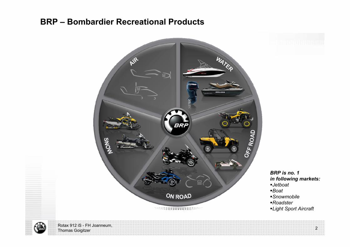
BRP – Bombardier Recreational Products
2Rotax 912 iS - FH Joanneum, Thomas Goigitzer
BRP is no. 1 in following markets:§Jetboat§Boat§Snowmobile§Roadster§Light Sport Aircraft

BRP-Powertrain GmbH & Co KG, Gunskirchen, Austria
3Rotax 912 iS - FH Joanneum, Thomas Goigitzer
n 1.100 employees
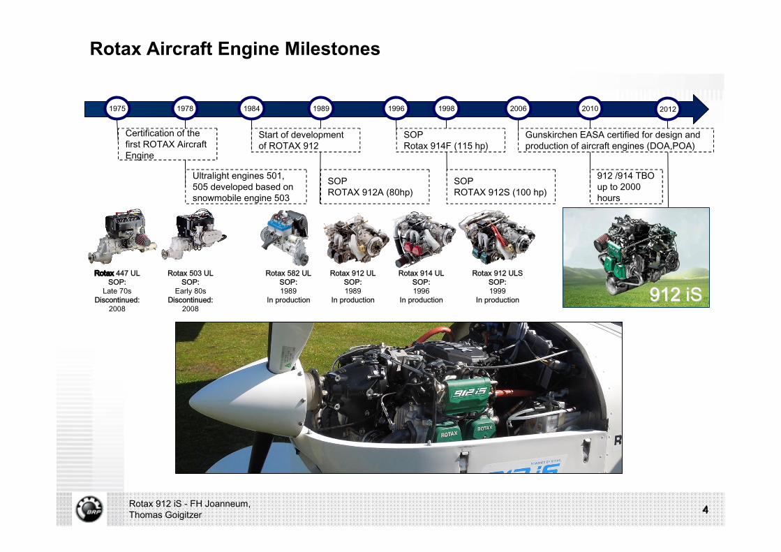
Rotax Aircraft Engine Milestones
4Rotax 912 iS - FH Joanneum, Thomas Goigitzer 4
Ultralight engines 501, 505 developed based on snowmobile engine 503
1975 1978
Certification of the first ROTAX Aircraft Engine
1984
Start of development of ROTAX 912
SOP ROTAX 912A (80hp)
1989 1996
SOPRotax 914F (115 hp)
SOPROTAX 912S (100 hp)
1998 2006
Gunskirchen EASA certified for design and production of aircraft engines (DOA,POA)
912 /914 TBO up to 2000 hours
2010
4
Rotax 447 ULSOP:
Late 70sDiscontinued:
2008
2012
Rotax 503 ULSOP:
Early 80sDiscontinued:
2008
Rotax 582 ULSOP:1989
In production
Rotax 912 ULSOP:1989
In production
Rotax 912 ULSSOP:1999
In production
Rotax 914 ULSOP:1996
In production 912912 iSiS
INDEX
§ Fuel Efficiency
§ Electric & Electronics
5Rotax 912 iS - FH Joanneum, Thomas Goigitzer
§ Control Strategy
§ Q&A
§ Mechanical Impact
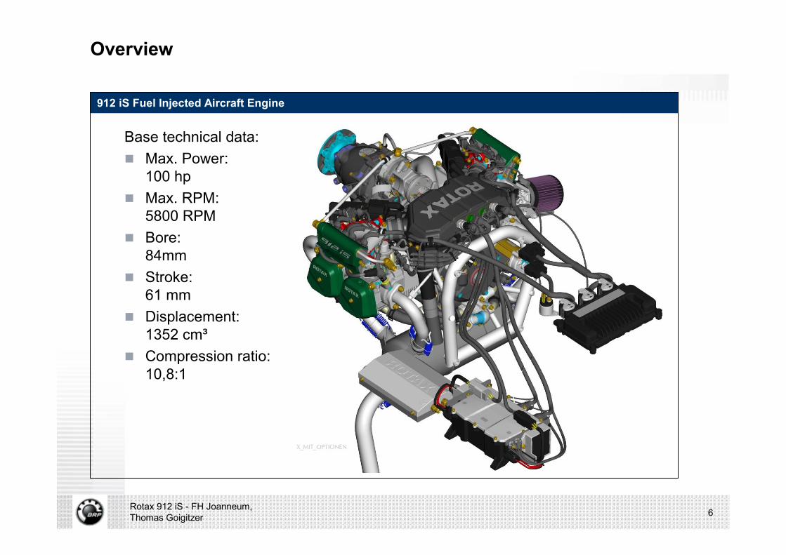
Overview
912 iS Fuel Injected Aircraft Engine
Base technical data:n Max. Power:
100 hpn Max. RPM:
5800 RPMn Bore:
84mmn Stroke:
61 mmn Displacement:
1352 cm³n Compression ratio:
10,8:1
Rotax 912 iS - FH Joanneum, Thomas Goigitzer 6

Overview
912 iS Fuel Injected Aircraft Engine
Rotax 912 iS - FH Joanneum, Thomas Goigitzer 7
Human
Mechanics Electrics
Eyes/EarsHands/Feet
Eyes/EarsHands/Feet
Human
MechanicsElectrics/
Electronics
Control Calibration
912ULS 912iS
1989 2012
Fuel Efficiency
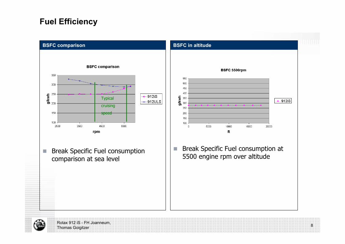
BSFC comparison
n Break Specific Fuel consumption comparison at sea level
BSFC in altitude
n Break Specific Fuel consumption at 5500 engine rpm over altitude
Rotax 912 iS - FH Joanneum, Thomas Goigitzer 8
Typical
cruising
speed
Fuel Efficiency
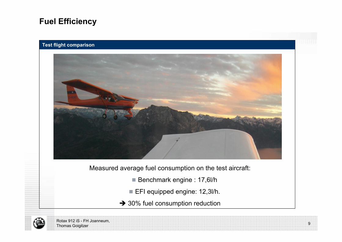
Test flight comparison
Measured average fuel consumption on the test aircraft:
n Benchmark engine : 17,6l/h
n EFI equipped engine: 12,3l/h.
è 30% fuel consumption reduction
Rotax 912 iS - FH Joanneum, Thomas Goigitzer 9

Electric & Electronics
Requirements The 912iS Engine Management System
n ECU consists of two separate control units, so called “Lanes”
n Redundant engine control system is capable of managing the redundant components
n Redundant implementation of all safety-critical sensors and actuators
Rotax 912 iS - FH Joanneum, Thomas Goigitzer 10
Requirement:Electronic fuel injection
Requirement:Aviation safety
Highly redundant Engine Management System
with intelligent redundancy management
Lane A Lane B

Electric & Electronics
Implementation of safety-critical sensors
Rotax 912 iS - FH Joanneum, Thomas Goigitzer 11
Redundant actuators Redundant sensors
Electric & Electronics
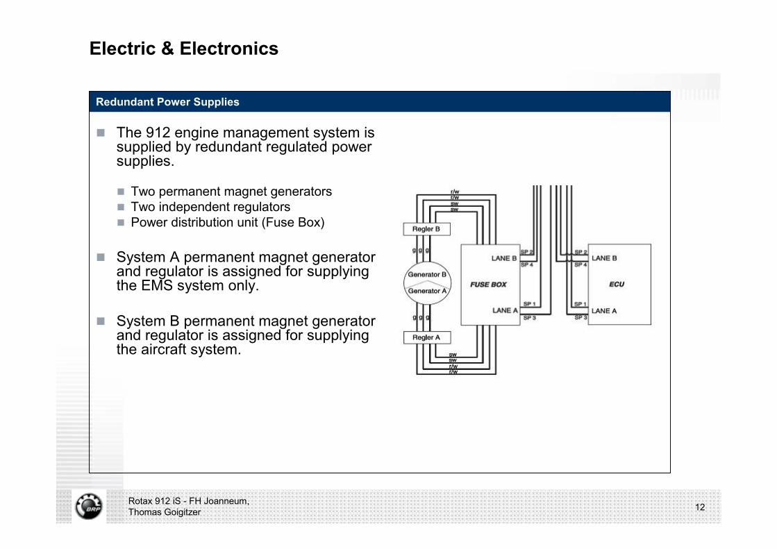
Redundant Power Supplies
n The 912 engine management system is supplied by redundant regulated power supplies.
n Two permanent magnet generators n Two independent regulators n Power distribution unit (Fuse Box)
n System A permanent magnet generator and regulator is assigned for supplying the EMS system only.
n System B permanent magnet generator and regulator is assigned for supplying the aircraft system.
Rotax 912 iS - FH Joanneum, Thomas Goigitzer 12
Electric & Electronics
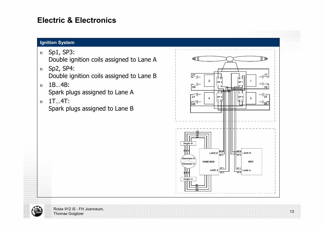
Ignition System
n Sp1, SP3: Double ignition coils assigned to Lane A
n Sp2, SP4: Double ignition coils assigned to Lane B
n 1B…4B: Spark plugs assigned to Lane A
n 1T…4T: Spark plugs assigned to Lane B
Rotax 912 iS - FH Joanneum, Thomas Goigitzer 13

Electric & Electronics
Injection system
Auto AB mode
Auto A mode
Auto B mode
Rotax 912 iS - FH Joanneum, Thomas Goigitzer 14
Auto_AB
Auto_A, Only_ A
Auto_B, Only_ B
Electric & Electronics
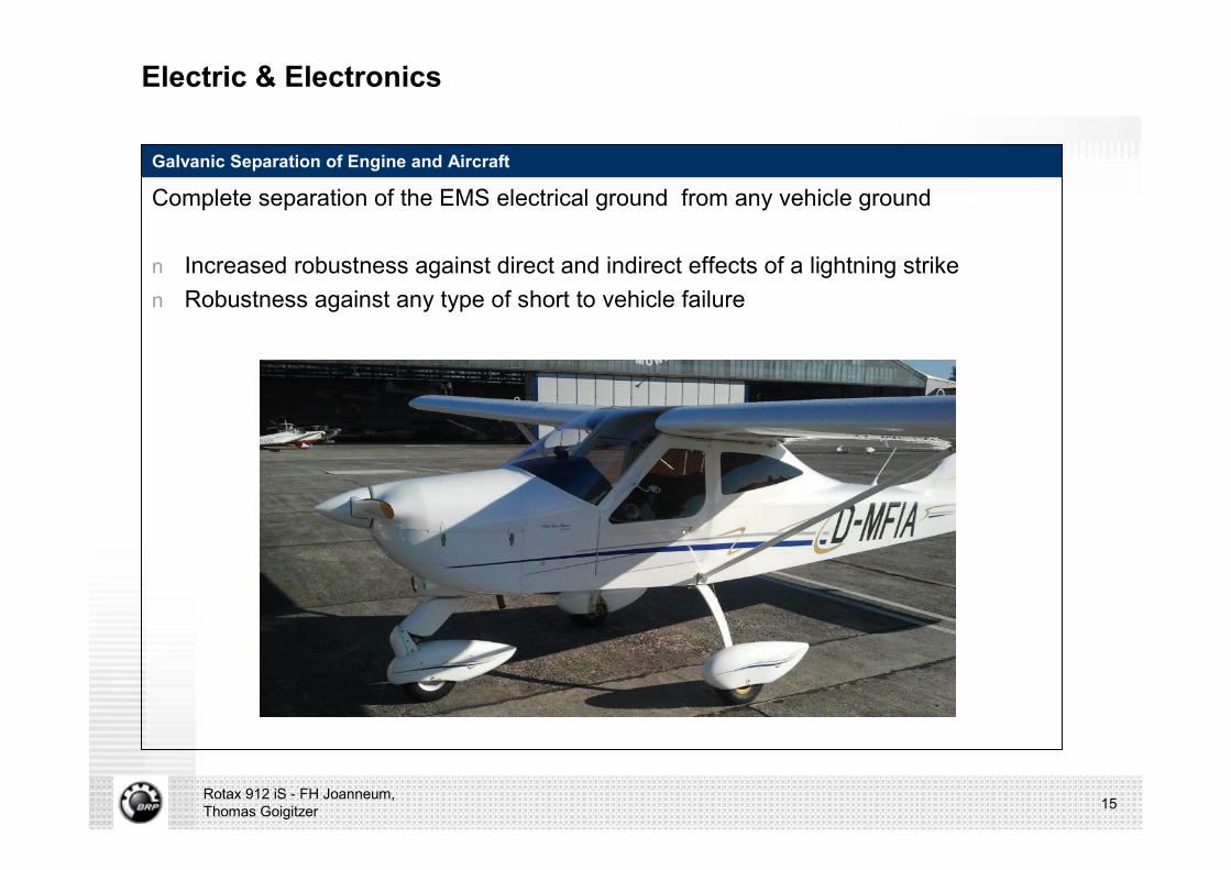
Galvanic Separation of Engine and Aircraft
Complete separation of the EMS electrical ground from any vehicle ground
n Increased robustness against direct and indirect effects of a lightning striken Robustness against any type of short to vehicle failure
Rotax 912 iS - FH Joanneum, Thomas Goigitzer 15
Control Strategy
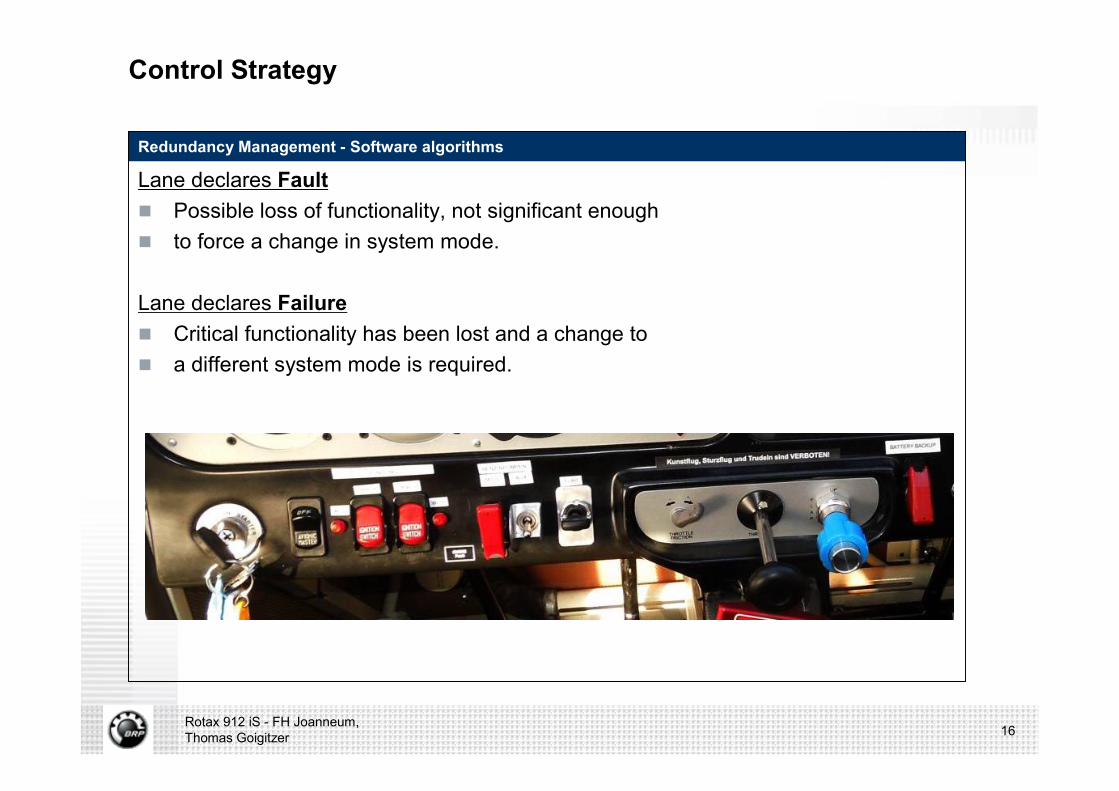
Redundancy Management - Software algorithms
Lane declares Faultn Possible loss of functionality, not significant enoughn to force a change in system mode.
Lane declares Failuren Critical functionality has been lost and a change to n a different system mode is required.
Rotax 912 iS - FH Joanneum, Thomas Goigitzer 16
Control Strategy
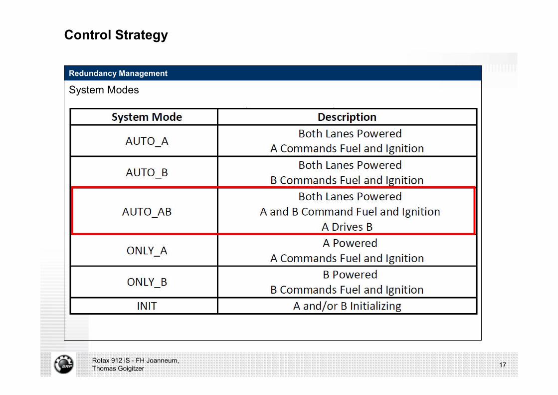
Redundancy Management
System Modes
Rotax 912 iS - FH Joanneum, Thomas Goigitzer 17

Electric & Electronics
Redundancy Management
Warning lamp matrix:
Rotax 912 iS - FH Joanneum, Thomas Goigitzer 18

Mechanical Impact
Overview
The Implementation of this unique EMS System forced nearly allmechanical systems on the engine to be changed:
n Crankcase: changedn Cranktrain: changedn Cylinderhead: changedn Gearbox/ transmission: changedn Induction system: changedn Fuel system: changedn Lubrication system: changedn Exhaust system: changedn Engine management system: changedn Cooling system: unchangedn Electric components: changed
Rotax 912 iS - FH Joanneum, Thomas Goigitzer 19
Mechanical Impact
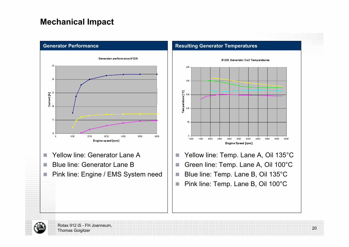
Generator Performance
n Yellow line: Generator Lane An Blue line: Generator Lane Bn Pink line: Engine / EMS System need
Resulting Generator Temperatures
n Yellow line: Temp. Lane A, Oil 135°Cn Green line: Temp. Lane A, Oil 100°Cn Blue line: Temp. Lane B, Oil 135°Cn Pink line: Temp. Lane B, Oil 100°C
Rotax 912 iS - FH Joanneum, Thomas Goigitzer 20
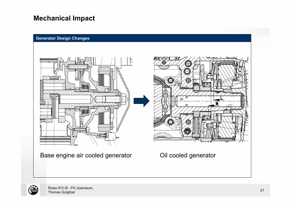
Mechanical Impact
Generator Design Changes
Rotax 912 iS - FH Joanneum, Thomas Goigitzer 21
Base engine air cooled generator Oil cooled generator

Questions?
22Rotax 912 iS - FH Joanneum, Thomas Goigitzer
Rotax 912 iS - FH Joanneum, Thomas Goigitzer 23
Recommended