ROOFTOP PACKAGED UNIT
Technical Manual
0
ROOFTOP PACKAGED UNIT
COMPANY
WITH QUALITY SYSTEM
CERTIFI
TECHNICAL BOOKLET
ED BY NGV
===ISO 9001:2000 ===

CONTENT
UNIT DESCRIPTION AND TECHNICAL DATA……………………………………………………………………………...2 ● Preface and Features……………………………………………………………………………………………………………………………....2
● Components or Assembly Descriptions………………………………………………………………………….………………………………...3
● Standard Features……………………………………………………………………………………………………………………………………4
▼ Standard Features………………………………………………………………………………………………………………...........................4
▼ Electrical features………………………………………………………………………………………………………….………………………..4
▼ Refrigeration features………………………………………………………………………………………………...……………………………..5
● Optional Features…………………………………………………………………………………………………….……..………………………..5
▼ Construction options…………………………………………………………………………………………………………………………………5
▼ Electrical options…………………………………………………………………………………..…………………………………………………5
▼ Refrigeration options………………………………………………………………………………………………..……………………………....6
● Refrigerant Piping Diagram (Sample only)…………………………………………………………………………..………..............................6
NOMENCLATURE………………………………………………………………………………………………………………..6 TECHNICAL DATA……………………………………………………………………………………………………………….7 ●10-22Kw………………………………….……………………………………………………………………………………………………………..7
●25-42Kw………………………………………………………………………………………………………………………………………………...8
●48-105Kw……………………………………………………………………………………………………………………………………………….9
●120-190Kw…………………………………………………………………………………………………………………………………………….10
CONTROLLER………………………………………………………………………………………………………………………………………….11
EXPLODED COMPONENTS VIEW (Sample only)………………………………………………………………………………………………..18
OVERALL DIMENSION…………………………………………………………………………………………………………………….………....19
INSTALLATION AND MAINTENANCE…………………………………………….…….………………………………………………..…21 PREFACE………………………………………………………………………….………………………………………………………………….21
SECTION I SAFETY………………………………………………….……………………………………………….…………………………..21
SECTION II INSTALLATION…………………………………………………………………………………………………………..…...……..22
SECTION III OPERATION……………………………………………………………………………………………………………..……………24
SECTION IV MAINTENANCE………………………………………………………………….………………….………………………….…...26
Typical installation
CONTENT
When installing or carrying out operations on the unit, closely follow the recommendations and
procedures given in this manual, observe warnings on the machine and take all precautionary
measures as required by the situation. Failure to comply with the procedures recommended by
this manual or unauthorized modification to the unit will automatically render the guarantee null
and void.
Cardiff reserves the right to alter the features of their products without the
interests of continuous improvement.
notice in
2
IPTION AND TECHNICAL DATA
Performance. These systems have been designed and tested to perform in ambient conditions as low as -10°C and as high as 45°C For the models from CAAHP 25 to CAAHP 190 belt drive fan motors are used to match the supply air requirements. The smaller units( models from CAAHP 10 to CAAHP 20 ) have 3 speed direct drive fans for adjusting air flows. Durable. Our packaged systems are bexcellent return on your investment. Tenvironments, e.g. salt laden sea airweather protection. External fastene inless steel or galvanized type. Corrosion resistant drain trays are also included. Insulatio s are gen tion and contain noise. More Safe. The refrigeration system includes a number of protection facilities, including: HP and LP switches, phase sequence relay, circuit breaker control etc.
UNIT DESCRIPTION AND TECHNICAL DATA PREFACE AND FEATURES
UNIT DESCR
PREFACE CARDIFF Rooftop Packaged Units are single packaged units which are factory assembled, tested and shipped completely with compressor, evaporator and condenser coils, fans and controls. These packages are designed for outdoor installation,and they may be used for cooling only or cooling and heat pump. The units are ideal for residential, commercial and industrial applications and are available in nominal cooling capacity from9.9 kW to 188.5 kW. Quality design and construction make CARDIFF air-cooled rooftop package units with hermetic scroll compressors the preferred applications and easy installation and maintenance. Operation range of outdoor temperature is from -10℃ to 45℃. Rooftop packaged systems are unobtrusive, quiet, and designed to provide year round comfort – warming in winter and cooling in summer. CARDIFF's wide product range offers a unit of performance capacity to suit small to large packaged air conditioner applications, e.g. offices, shops, motels, fast food outlets, restaurants, petrol stations, open plan office and work spaces, supermarkets, shopping malls and auditoriums. Units are suited to high static pressure applications where large volume spaces are to be air conditioned. Long pipe and ductruns are possible enabling greater installation flexibility. This range of units has been developed to meet the needs of typical applications. Should you have special requirements, such as higher air flows or greater sensible duty units contact your nearest CARDIFF representatives. CARDIFF engineers have extensive experience in designing air conditioning equipment for specific applications.
11-49110000 FEATURES Efficient. These reverse cycle (heat pump) air conditioners provide one of the most efficient forms of heating you can invest in. For every 1 kW of power consumed, up to 2.8 kW of heat is generated. For every 1 kW of power consumed, up to 3.1 kW of heat is generated. Each outdoor unit incorporates high efficiency scroll compressors. Heat exchange coils use high efficient tube for better heat transfer.
.
uilt tough to withstand all weathers. Their durable construction ensures a long life and he out oor air coils' aluminum fins are epoxy coated for extra protection in corrosive . Cabinets are constructed from high grade steel - polyester powder coated for all rs are ta
d
s
n. Indoor air section erously insulated to reduce condensa

Economy. Some models feature the flexibility and economy of 2~4 stages operation. Compressors are progressively
3
switched on only as they are needed. This has the added advantage of lowering start-up current.
conomizer Option. If the outdoor air heat content or temperature is below that of the return air, a fresh air damper opens amper closes to provide the first stage of cooling. Operating costs are reduced as the compressor(s) will
nly operate to provide more cooling if it is required.
recommended and are available as options.
,
cts — chosen because of their proven efficiency, durability, performance, reliability and value. asy service. Quick release fasteners are provided on electrical and compressor panel.
Assembly Descriptions
) Quiet operation. The packaged Rooftop series are basic constructed and engineered with noise reduction as a first
d to their operating position through the lifting supports available on the units. ) Capacities to Fit. There is a large production line of packaged units, with capacities ranging from 9.9 to 188.5kW for 50
thickness luminum frame filter that slides out or easy cleaning or replacement.
erformance at all design conditions. Coils are manufactured from seamless copper tubes mechanically expanded to aluminum fins. All coils are tested at 30kg/cm2 (450 Psi) air pressure, under water to avoid leakage. They also
) Direct Driven Condenser Axial Fans. All condenser fans are of the axial type, which are directly mounted on the motor
tically and dynamically balanced before Installation. CARDIFF tries its bests to
Eand the return air do Fresh Air Introduction. An optional fresh air damper is available for most models. For applications using high proportions of fresh air (50%+) a hot gas bypass and HP fan speed controller are Peace of mind. The manufacturer operates a quality management system that conforms to international standard like CEISO14001, ISO9001:2000. CARDIFF products have been chosen, against worldwide competition, for use in some of themost exclusive projeE Quiet design. Apartments are provided on electrical and compressor section, low noise.
WITH CE CERTIFICATE WITH ECONOMIZER
IS OPTIONAL
Components or Aconsideration, low noise mounted fans are used, 15mm wave type acoustic Insulation for compressor section and compressors are mounted on vibration isolators. B) Low Cost Installation. Units are factory assembled and pre-charged, with a single point electrical connection. On arrival to the job site they are ready to be lifteCHz refrigeration tons at nominal conditions. D) Casing. Heavy grade steel casing with polyester epoxy powder electrostatic oven-baked paint of coating finish, designed for outdoor installation with 10mm insulation for evaporator section only. All units are provided with an 8mmaE) Compressor. The compressor used is hermetic refrigerant gas cooled, with internal thermal protection in each phase, scroll type. The terminal boxes are rain tight, starting is direct-on-line. With high efficiency, low sound, so as to match all other CARDIFF products’ reliability and efficiency. F) Evaporator and Condenser Coils. The evaporator and condenser coils are designed to deliver their respective duties at optimum pinundergo dry chemical cleaning after manufacturing for optimum system cleanness. Gshaft. All fans are selected for optimum efficiency and for maximum sound power reduction. Fan blades are made for maximum corrosion resistance, and are sta
4
rrent overload protected, ith class “IP56” electrical insulation.
) Evaporator Fan Motors. Motors are of the totally enclosed induction type, with fan motor assembly placed on a floating
d and with lass “B” insulation. Fan motors with V-belt-driven type are of 1 speed type.
ll units are provided with a drain pan having drain connection from one side. The drain pan is painted galvanized steel type nd insulated on the underside to prevent condensation.
All units are internally lined thermal insulation for coil and fan section (evaporator side only). N) Easy Installation The package rooftop has a compact design. It is supplied as a complete package ready for operation, with no extra controls or other items to be installe single power point entry with units are designed to ensure maximum complian tional standards. Quick start-up is assured once installation is completed, as each rooftop unit is manufactured in an ISO9001:2000 listed facility to guarantee quality. ll units are tested at the factory to provide reliable start up.
l panels.
and protecting devices seated against client requirement.
r.
ensure the low noise operation with high efficiency. All condenser fans are equipped with wire guards. H) Condenser Fan Motor. All fans motors are of totally enclosed air-cooled, internal thermal cuwI) Belt Drive Evaporator Fan. Fans are of the centrifugal type that is designed for maximum efficiency for uniform air distribution. V-belt driven with variable pitch pulley as optional. All fans are statically and dynamically balanced to ensure quiet operation and smooth performance. Jbase with a flexible connection at the fan/casing interface. All fan motors of direct-driven are of the 3-speed type, highly efficient induction type motors, totally enclosed air-cooled, squirrel-cage type, internal thermal current protectecK) Filters All Models are provided with 8mm thickness aluminum frame filter (as standard features). Other filters are available upon request. L) Drain Pan AaM) Insulation
with 10mm
d. The units have a simple connections. All ce with interna
A Standard Features Easily accessible system components. Ample space for easy access to power and controHeavy duty mounting chassis for the whole unit with lifting holes. Anti-vibration mounting compressor. Weather-proof, polyester epoxy powder electrostatic paint oven-baked finish for sheet metal and base frame. All units are shipped out from factory tested 8mm nylon filer as standard for Returning air inlet. Single skin evaporator side with 10mm thermal installation. Condenser coil with treated blue fins. Quick release fasteners to be provided on electrical and compressor apartment cabinet. Electrical features:
Control and power panels include the direct-on-line starting contactors for the compressors and condenser fan motor.
Internal thermal motor protector for condenser and evaporator fan moto Compressor internal thermal protection. Anti-recycling protection (time delay) for compressors through microprocessor. Crank case heater for each compressor.
5
peration to ensure longer life for the compressors and equal running hours between
tem.
anel. It can be used with a shielded cable at a distance of 20m.
tion features: igh efficient Hermetic scroll compressor.
ermal expansion valve (for mod. 72 and above only).
zing lines installed between parallel installed compressors
type. 3. Evaporator with treated anti-corrosion protection for coils (blue fins)for copper/aluminum coils only.
r “50mm(2”)” thick flat filter. sh, return and exhaust air dampers with cowl.
he ability to work with free cooling or free heating mode allowing uch as possible, since it avoids turning on the heaters and
nction can be achieved by controlling the opening/closing of the external air damper. e indoor air
lso required a sealed + drain condensing section.
1. Power circuit breaker for each motor.
er molded case circuit breaker for the whole unit (can also be available with an external handle as an option).
3. Low ambient control:
it to operate in low ambient condition a head pressure control can be Installed either by:
Control circuit breaker. Microprocessor controller with the following main functions:
■Compressor lead-lag ocompressors.
■External remote ON/OFF button for remote operation of the unit using external ON/OFF switch or connection to building management sys
■Volt-free terminals available for general alarm indication signal to remote monitoring station. ● Dual power supply input. ● High and low pressure safety switches (capsule type, factory Pre-set) from all models. ● Remote control panel with the same functions as the on-board p
Refrigera
1. H2. Filter drier (for mod. 63 and above only). 3. Charging points pin valve. 4. Th5. Fully charged unit with refrigerant. 6. Oil equali
Optional Features
A)Construction options: 1. Metal mesh on condenser section. 2. Optional supply/return air configurations, optional bottom supply and return
4. “25mm (1”)” o5. Economizer option with fre
If this option is installed in the unit the unit has tit to exploit the external environmental condition as mthe compressors. This fuWith reference to the difference between the outdoor air temperature(std)/enthalpy and thtemperature(std)/enthalpy.
6. High Static condenser fan option will a7. Upgraded Evaporator Fan Motor Drives. B)Electrical options:
2. Main pow
The refrigeration systems in all unit are inherently designed to operate efficiently, without extra controls or modifications. To
permit the un
ON/OFF condenser fans sequencing (for models with 2 condenser fans).
3 speed of the condenser fan motor.
4. Earth leakage relay for each compressor.
5. Earth leakage relay for the whole unit.

6
each motor.
8.
9. B system interface. Interfacing with other building management systems can be Achieved by an optional
10. Vo ence relay) for monitoring the main incoming power supply for the unit which
n heat pump option.
3. e low-local situation occurs and where it is necessary avoid low suction pressure and “compressor
cycling”)
ant accessories such as suction accumulators (for cooling units only), refrigerant liquid receivers, oil
er for models
6. External overload relay for
7. Power factor correction capacitor.
Automatic or manual provision for pump down operation of each compressor stop.
uilding automation
card which can communicate with other devices using the serial communication port.
ltage monitor controller (phase sequ
provides protection from single-phasing, under-voltage, phase-voltage imbalance and phase-non-sequence
Refrigeration options: 1. Heat pump packaged unit with 4-way reversing valve, suction accumulator is a standard feature i
2. Pressure gauges for each refrigeration circuit (high/low pressure gauges).
Hot gas bypass (wher
4. Extra refriger
separators etc..
5. Solenoid valve for heat pump mode.
6. High and low pressure controll
Refrigerant Piping Diagram (Sample only)
1 COMPRESSOR 7 SINGLE WAY VALVE
2 HIGH PRESSURE SWITCH 8 EXPANSION VALVE (or CAPILLARY)
3 REVERSING VALVE (HEATING MODEL ONLY) 9 SINGLE WAY VALVE
4 LOW PRESSURE SWITCH 10 EXPANSION VALVE or CAPILLARY
5 PIN VALVE 11 FILTER 6 OIL SEPARATOR Refrigerant Piping Diagram (Sample only)
UNIT DESCRIPTION AND TECHNICAL DATA NOMENCLATURE
NOMENCLATURE
C AA H C P 10 ⑥
①②
③ C: Cooling only
BC: R407c
⑤ Type of unit P: Packaged type S: Split type
⑥ Model ① ② ③ ④ ⑤ C: Cardiff products Unit type
H: Heat pump ④ Refrigerant type
--: R22 AA: Air to Air A: R410a
: R134a AW: Air to Water WA: Water to Air WW: Water to Water
7
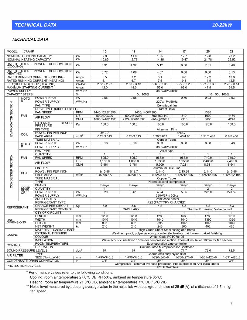
MODEL
TECHNICAL DATA 10-22kW
TECHNICAL DATA
CAAHP 10 12 14 17 20 22 NOMI N 8 23.2 AL COOLING CAPACITY kW 9.9 11.6 13.5 17.7 19.NOMINAL 25.52 HEATING CAPACITY kW 10.89 12.76 14.85 19.47 21.78 RATED TOT (COOLING) kW 3.91 4.32 5.12 6.50 7.31 8.49 AL POWER CONSUMPTION
RATE(H 8.13 D TOTAL POWER CONSUMPTION kW 3.72 4.08 4.87 6.08 6.60 EATING) RATE 8.1 9.8 12.2 13.6 D RUNNING CURRENT (COOLING) Amps 6.5 7.2 RATE D RUNNING CURRENT (HEATING) Amps 6.1 6.7 7.5 9.1 11.5 12.5EE 14 R (COOLING) / COP (HEATING) kW/kW 2.53/2.92 2.68/3.13 2.63/3.05 2.72/3.20 2.71/3.30 2.73/3.MAXIMUM S T Amps 42.0 48.0 55.0 66.0 47.5 54.5 TARTING CURRENPOWER V/Ph/Hz 380V/3Ph/50Hz SUPPLY CAPACITY STEPS % 0、100% 0、50、100%
POWER INPUT kW 0.55 0.55 0.55 0.76 0.93 0.93 MOTOR POWER SUPPLY V/Ph/Hz 220V/1Ph/50Hz
FAN TYPE Centrifugal fan DRIVE TYPE (DIRECT / BELT) Direct Drive FAN SPEED RPM 1440/1245/1390 1430/1400/1360 1380
L/S 500/400/320 590/480/370 700/550/440 810 1000 1180 AIR FLOW CMH 1800/1440/1152 2124/1728/1332 2520/1980/1584 2916 3600 4248
FAN
EXTERNAL STATIC Pa 160.0 PRESSURE 150.0 180.0 180.0 170.0 150.0
FIN TYPE Aluminum Fins ROWS / FIN PER INCH 3/12.7 4/12.7 FACE AREA m2/ft2 0.28/3.013 0.28/3.013 0.28/3.013 0.46/4.95 0.51/5.488 0.6/6.456 EV
APO
RA
TE
ON
COIL
TUBE MATERIAL Copper Tubes
CTI
OR
S
POWER INPUT kW 0.16 0.16 0.33 0.38 0.38 0.48 MOTOR POWER SUPPLY V/Ph/Hz 380V/3Ph/50Hz
FAN TYPE Axial type QUANTITY 1 1 1 1 1 1 FAN SPEED RPM 695.0 695.0 965.0 965.0 710.0 710.0
L/S 1,100.0 1,050.0 1,530.0 1,950.0 2,400.0 2,400.0 FAN
AIR FLOW CMH 3,961 3,781 5,509 7,021 8,641 8,641 FIN TYPE Aluminum Blue Fins ROWS / FIN PER INCH 2/15.88 3/12.7 3/14.0 2/15.88 3/14.0 3/15.88 FACE AREA m2/ft2 0.825/8.877 0.825/8.877 0.825/8.877 1.125/12.105 1.125/12.105 1.125/12.105COIL
TUBE MATERIAL Copper Tubes TYPE Hermetic scroll compressor BRAND Sanyo Sanyo Sanyo Sanyo Sanyo Sanyo QUAN Y 1 1 2 2 TIT 1 1POWE N 3.20 3.61 5 2x3.0 2x3.52 R I PUT kW 4.24 5.3POWE UR S PPLY V/Ph/Hz 380V/3Ph/ 50Hz
CO
ND
EN
SER
SE
CTI
ON
COMPRESSOR
ANCIL RLIA IES Crank case heater REFRI R ) GE ANT TYPE R22 (FACTORY CHARGEDCHAR P 3.6 6.2 7.3 GE ER CIRCUIT Kg 3.0 4.2 5.8REFRI R CAPILLARY Valve control GE ANT CONTROL Thermal ExpansionREFRIGERANT
QTY O I 1 1 1 F C RCUITS 1 1 1 LENG 1280 1280 1660 1780 1780 TH mm 1280 WIDTH 1040 1040 0 1040 1390 1390 mm 104HEIGH 895 895 5 1045 T mm 895 1045 104
UNIT DIMENSIONS
NET W H 240 240 420 EIG T kg 243 360 402 MATERIAL - CASING / BASE High Grade Sheet Steel casing and frame EXTERNAL FINISHING Weather-proof, polyester epoxy powder electrostatic paint oven-baked finishing COLOUR White, Code PCTC70105 CA
section
SING
INSULATION Wave acoustic insulation 15mm for compressor section. Thermal insulation 10mm for fan ROOM TEMPERATURE Easy operation Line controller CONT Unit mounted Microprocessor Controller ROL OPERATION
SOUND P db(A) 67 67 68 71.7 72.6 72.6 RESSURE LEVELS TYPE Coarse efficiency Nylon filter AIR FILTER m 1-790x340x8 1-790x340x8 1-788x276x 31x420x8 1-831x420x8SIZE (No.-LxWxH) m 1-790x340x8 8 1-8
CO ENSATE D 3/4" 3/4" 3/4" 3/4" ND RAIN CONNECTION in 3/4" 3/4" Compressor - external overload protection, Phase protection Anti-cycle timersPROTECTION DEVICES HP/ LP Switches
* the following conditions: perature 27.0°C DB RH 50%, am perature 35°C;
Hea ature 21.0°C DB, ambient ai B / 6°C WB ** Nois dopting average value in th ith background noise of 25 dB(A), at a distance of 1.5m high
fan s
Per es refer toformance valuCool
ing: room air temti
bient air temng: room air temper r temperature 7°C D
e level measured by a e noise lab wpeed.

8
TECHNICAL DATA
MODEL CAAHP 25 28 30 32 35 42
TEC NICAL DATA 25-42kW H
NOMI NAL COOLING CAPACITY kW 25.2 27 3 3 430.2 2.4 5.6 1.6 NOMINAL HEATING CAPACITY kW 27.3 7 34.29. 32.4 6 38 44.6 RATED TOTAL POWER CONSUMPTION (COOLING) kW 9.71 31 10. 11.16 11.30 12.74 14.70 RATED TOTAL POWER CONSUMPTION (HEATING) kW 9.12 9.79 10.32 10.55 11.60 13.14 RATED RUNNING CURRENT (COOLING) Amps 15.1 .0 117 18.5 9.6 23.1 27.9 RATED RUNNING CURRENT (HEATING) Amps 14.0 6 17. 21.15. 17.2 8 6 26.1 EER (COOLING) / COP (HEATING) kW/kW 2.82/2.99 /3.03 2 4 2.8 2.7 2.8 9 2.62 .71/3.1 7/3.28 9/3.28 3/3.3RATED RUNNING CURRENT (COOLING) Amps 15.1 0 19. 23.17. 18.5 6 1 27.9 MAXIMUM STARTING CURRENT Amps 61.5 5 562. 62.9 9.9 75.3 87.9 POWER SUPPLY V/Ph/H / 3Pz 380V h/50H zCAPACITY STEPS % ,54,100 0 0 0,46 0,50,10 0 10,46,54, 0,5 0,100 0,5 0,100 0,3 1007,63,
POWER INPUT kW 1.22 22 1. 1.5 1.5 2.2 2.2 MOTOR POWER SUPPLY /Ph/Hz 0Hz V 380V/3Ph/5FAN TYPE Centrifugal fan D T / BELT) e RIVE TYPE (DIREC Belt DrivF PM 1320 1320 1120 940 940 AN SPEED R 1400
L/S 1250 1500 1750 1890 2200 1580 AI CMH 0 5 6300 680 7920 R FLOW 450 5400 688 4
FAN
E TIC PRESSUR Pa 5 2XTERNAL STA E 25 235 305 90 270 250 F inum FiIN TYPE Alum ns RO 0/ 3. 4 WS / FIN PER INCH 4. 12.7 0/ 12.7 .0/ 12.7F m2/ft2 0.6/6.456 6.532 1 0.7 0.9 0. 4 ACE AREA 0.607/ 0.633/6.81 32/7.877 52/10.244 952/10.24
EVAP
OR
ATO
R S
ECTI
O
COIL
T bes
N
UBE MATERIAL Copper TuP kW 0.61 0.61 2x0.37 2x0.45 OWER INPUT 0.80 0.80 MOT P V/Ph/H / 3PhOR OWER SUPPLY z 380V / 50Hz FAN TYPE Axial type Q 1 1 UANTITY 1 1 2 2 F PM 920 20 AN SPEED R 9 710 940 950 940
L/S 2620 2620 3420 2x2083 2x2444 3120 FAN
AI CMH 9434 9434 11 123 2x7500 2x8800 R FLOW 234 14 F BlueIN TYPE Aluminum F insR R INCH 3/15.88 .88 3OWS / FIN PE 3/15 3/14.0 /15.88 3/14.0 3/12.7 F m2/ft2 1.44/15.50 5.50 1 1.9 2 7 ACE AREA 1.44/1 1.8/19.37 .8/19.37 8/21.305 .47/26.57COIL
TUBE M AL
ATERI Copper Tubes T or YPE Hermetic scroll compressB anyo RAND S Sanyo Sanyo Sanyo Sanyo Sanyo Q 2 UANTITY 2 2 2 2 2 P kW 3.3+3.8 2x4.24 2x4.9 4.2+7.4 OWER INPUT 4 2x4.5 .06+4.8 P UPPLY V/Ph/Hz OWER S 380V / 3Ph / 50Hz
CO
ND
EN
SER
SE
CTI
ON
COMPRESSOR
A k case hNCILLIARIES Cran eater R R2 ACTORY CHARGED) EFRIGERANT TYPE 2 (FC UIT 8.1 .4 1HARGE PER CIRC Kg 8 9.8 0.5 12.0 5+9.2 R TROL Th alve control EFRIGERANT CON ermal Expansion V
REFRIGENT
Q 1.0 1 2 2
RA
TY OF CIRCUITS 1 1 LE mm 1940 0 254 254 NGTH 194 2240 2240 0 0W mm 1390 0 1IDTH 139 1390 390 1 1860 860 H mm 1045 5 1045 104 5 EIGHT 104 5 1045 119
UNIT DIMENSIONS
N kg 461 5ET WEIGHT 461 503 05 650 725 M CASING / BASE High G eet Steel c nd frame ATERIAL - rade Sh asing aE FINISHING Weathe f, polyester e owder elec paint ove d finishinXTERNAL r-proo poxy p trostatic n-bake g C , Code PCTOLOUR White C70105 CASING
IN Wave acoustic i nsula 0mm for fan on SULATION nsulation 15mm for ressor sectio ermal icomp n. Th tion 1 sectiROOM TEMPERATURE Easy operation Line controller CONTROL OPERATION U r Controller nit mounted Microprocesso
SOUND PRESSURE db(A) LEVELS 70.0 70.0 72.0 72.0 72.0 72.0TYPE Coarse efficiency Nylon filter AIR FILTER mm 2-502x395x8 2-502x 2-592x395x8 2-592x470x8 SIZE (No.-LxWxH) 395x8 772x502x8 2-502x395x8
CONDENSATE DRAIN CONNECTION in 3/4" 3/4" 33/4" /4" 3/4" 3/4" Compressor - protection An sexternal overload protection, Phase ti-cycle timerPROTECTION DEVI CES HP/ LP Switches
* Performance values refer to following con s: : room air temperature 27.0°C DB RH 50%, a
emperature 7°C DB / 6°C W of 25 dB(A), at a distance of 1.5m high
the ditionCooling mbient air temperature 35°C;
B Heating: room air temperature 21.0°C DB, ambient air t** Noise level measured by adopting average value in the noise lab with background noise
fan speed.

9
AHP 8 52 63 72 90
TECHNICAL DATA 48-105kW
TECHNICAL DATA
MODEL CA 4 105 NOMI NAL COOLING CAPACITY kW .2 2 63.3 71.4 .2 147 53. 87 03.1 NOMINAL HEATING CAPACITY W 2 4 67 6 k 50. 56. 75. 93.3 109.5 RATED TOTAL POWER CONSUMPTION W 7 .70 50 .30 0 (COOLING) k 16. 18 22. 26 31.4 38.30 RATED TOTAL POWER CONSUMPTION (HEATING) W 4 13 .07 25.55 k 16.0 18. 21 29.83 36.78 RATED RUNNING CURRENT (COOLING) ps 9 .7 0 .3 Am 30. 33 39. 48 55.6 69.7 RATED RUNNING CURRENT (HEATING) 7 .3 5 9 Amps 28. 31 36. 44. 52.7 66.6 EER (COOLING) / COP (HEATING) 3 .11 .18 .96 3 kW/kW 2.83/3.1 2.84/3 2.81/3 2.71/2 2.78/3.1 2 8 .69/2.9MAXIMUM STARTING CURRENT .4 Amps 103.9 108 111 114.2 154.1 197.7 POWER SUPPLY V/Ph/Hz 380V/3Ph/50Hz CAPACITY STEPS % 0 100 0,100 0,100 00 0 0 ,32,68, 0,40,6 0,50,100 0,5 0,50,1 ,50,10
POWER INPUT kW 3 3 3 4 4 5.5 M O T O R
ER SUPPLY Ph/Hz /3PPOW V/ 380V h/50Hz FAN TYPE Centrifugal fan DRIVE TYPE (DIRECT / BELT) Belt Drive FAN SPEED RPM 1000 750 850 850 900 750
L/S 0 0 0 0 260 290 3520 400 460 5400AIR FLOW CMH 0 40 672 400 0 936 104 12 14 1656 19440FAN
EXTEPRES
RNAL STATIC SURE 0 Pa 290 28 275 380 345 390
FIN TYPE Aluminum Fins ROWS / FIN PER INCH 4.0/ 12.7 FACE AREA m2/ft2 1.08/11.62 1.17 1.41/15.115 1.7/18.292 82 2 412.632 1.95/20.9 .21/23.780EV
APO
RA
OR
SE
TC
TIO
N
CO
IL
TUBE MATERIAL opperC Tubes POWER INPUT kW 2x0.55 2x0.55 2x1.1 2x1.5 2x1.5 2x0.75 M R
SO T O POWER UPPLY h/Hz V/P 380V/3Ph/50Hz FAN TYPE Axial type QUANTITY 2 2 2 2 2 2 FAN SPEED RPM 40 920 720 725 0 720 9 72
L/S 2x2611 3420 4166 55 2 2x2975 2x 2x 2x55 x5555FAN
AIR FLOW 00 710 0 CMH 2x94 2x10 2x12310 2x15000 2x2000 2x20000 FIN TYPE inum B Alum lue FinsROWS / FIN PER INCH 88 4.0 .7 3/13/ 15. 3/1 3/12.7 3/12 4.0 3/12.7 FACE AREA m2/ft2 7 2.108 0.357 357 6. 5 2.47/26.57 2.984/3 3.77/40.565 4.68/5 4.68/50. 44/69.29C
OIL
BE MATE AL
TU RI er Copp Tubes TYPE Hermetic scroll compressor BRAND Sanyo Sanyo Sanyo Sanyo Sanyo Sanyo QUANTITY 2 2 2 2 4 4 POWER INPUT kW 10.5 9.5 10.5 4.1+8.5 4.1+ 2x 2x 4x7.04 4x 1 7.POWER SUPPLY h/Hz 0V/3PhV/P 38 /50Hz
CO
ND
ER
SE
ON
IARIES
NSE
CTI
CO
MPR
ES
SOR
ANCILL Crank case heater REFRIGERANT TYPE R22 ED) (FACTORY CHARGREFRIGERANT CONTROL ol Thermal Expansion Valve contrREFRIGE
UITS 2 RANT
QTY OF CIRC 2 2 2 2 2 LENGTH mm 0 0 0 254 249 2490 2840 284 3410 WIDTH mm 0 0 10 2 186 205 2210 2210 22 210HEIGHT mm 5 90 0 80 119 13 149 15 1665 1810
UNDIMENS
NET WEIGHT 4
IT IONS
kg 801 88 890 980 1160 1450 MATERIAL - CASING / BASE High G heet Steel and frame rade S casing EXTERNAL FINISHING Weather- polyester powder el tatic paint ov baked finishi proof, epoxy ectros en- ng CASING COLOUR White,Code PCTC70105
INSULATION Wave ection acoustic insulation 15mm for compressor section. Thermal insulation 10mm for fan sROOM TEMPERATURE Easy operation Line controller CONTROL OPERATION Unit mounted Microprocessor Controller
SOUND PRESSURE LEVELS db(A) 75 73 75 75 73 75 TYPE Coarse efficiency Nylon filter AIR FILTER SIZE (No.-LxWxH) 2 8 x541x8 mm -592x470x 2-628 2-757x591x
83-761x391x
83-761x391x
82-7 x856x646
CONDENSA ECTION in 3/4" 3/4" 3/4" 3/4" TE DRAIN CONN 3/4" 3/4" C xtern protecti rotection ersompressor - e al overload on, Phase p Anti-cycle timPROTECTION DEVICES HP/ LP Switches
* Performance values refer to the following conditions: ient air temperature 35°C;
** f 25 dB(A), at a distance of 1.5m high
Cooling: room air temperature 27.0°C DB RH 50%, ambHeating: room air temperature 21.0°C DB, ambient air temperature 7°C DB / 6°C WB Noise level measured by adopting average value in the noise lab with background noise ofan speed.

TECHNICAL DATA 120-190kW
10
ATA
HP 120 130 150 170 190
TECHNICAL D MODEL CAANOMI NAL COOLING CAPACITY kW 118.8 131.2 153.4 168.6 188.5 NOMINAL HEATING CAPACITY kW 126.8 141.2 164.3 182 202
RATED TOTAL POWER CONSUMPTION (COOLING)
kW 46.10 70 .70 65.40 75.48 49. 56
RATED TOTAL POWER CONSUMPTION kW 42.90 70 .70 59.28 69.40 (HEATING) 45. 50
RATED RUNNING CURRENT (COOLING) Amps 86.5 9 5.7 . 14290. 10 116 0 .7 RATED RUNNING CURRENT (HEATING) Amps 82.0 2 0.5 . 13686. 10 111 0 .1 EER (COOLING) / COP (HEATING) kW/kW 57/2.96 64/3.09 .51/3.0 2.46/2.82. 2. 2.65/3.16 2 5 MAXIMUM STARTING CURRENT Amps 61 6 192 241 16 183 3 POWER SUPP V/Ph/H Ph/5LY z 3 /380V 0Hz CAPACITY STEPS % 0、25、50、75、100
POWER INPUT kW 7.5 7.5 11 15 7.5
MO
TOR
V/Ph/Hz POWER SUPPLY 38 z 0V/3Ph/50HFAN TYPE Centrifugal fan DRIVE TYPE (DIRECT / B Drive E Belt LT) FAN SPEED RPM 800 00 850 740800 8
L/S 6120 0 00 9200 1020675 81 0 AIR FLOW CMH 22032 00 160 33120 36720243 29 FAN
NAL STATIC Pa 390 385 420 430 EXTERPRESSURE 360 FIN TYPE Aluminum Fins FACE AREA m2/ft2 /27.1 9.3 /4 09/4 2.52 15 2.73/2 75 3.35/36.046 3.77 0.565 4. 4.009EV
APO
RA
TOR
SEC
TIO
N
CO
IL
RIAL TUBE MATE Copper Tubes POWER INPUT kW 4x0.75 0.75 4x1.5 4x1.5 4x 4x1.5
MO OR
T PLY V/Ph/Hz z POW RE SUP 380 0HV / 3Ph / 5
FAN T PY E Axial type QUANTITY 4 4 4 4 4 FAN SPEED RPM 940 940 720 720725
L/S 4x3420 3420 66 5555 4x5555 4x 4x41 4xFAN
OW CMH 12310 00 4x200AIR FL 4x 4x12310 4x15000 4x2 00 00 FIN TYPE Aluminum Blue Fins ROWS / FIN PER INCH 14.0 .0 .7 14 4/1 3/ 3/14 4/12 4/ .0 4.0 FACE AREA m2/ft /69.2 .32 5 7/72 6.44 95 7/75 7/75.32 7/7 .32 5.32 C
OIL
TUBE MATERIAL Copper Tubes TY E P Her roll com r metic sc pressoBRAN D Danfoss anfoss ss Danfoss DanfoD Danfo ss QUANTITY 4 4 4 4 4 POWER INPUT kW 4x8.9 9.8 4x12.2 4x13.64x 4x10.8 2 POWER S PU
CO
ND
EN
SER
SE
CTI
ON
OR
PLY V/Ph/Hz 380V / 3Ph / 50Hz
CO
MPR
ESS
ANCILLIARIES Crank case heater REFRIGERANT TYPE R22 (FACTORY CHARGED) CHARGE PER I C RCUIT Kg 2x22.5 2 30 2x35 x24 2x26.5 2x REFRIGERANT CONTROL Therma sion Va ol l Expan lve contr
RE
FRIG
OF CIRCUITS 2 2 2 2 2
ER
ANT
QTYLENGTH mm 4700 0 00 5800 5880520 55 WIDTH mm 2230 0 30 2230 2230223 22 HEIGHT mm 1640 20101640 1810 1810
UNIT DIMENSION
kg S
NET WEIGHT 1910 2010 2280 2460 2530 MATERIAL - CASING / BASE High G nd frame rade Sheet Steel casing aEXTERNAL FINISHING Weather-proof, polyester aint oven-baked finishing epoxy powder electrostatic pCOLOUR White,Code PCTC70105 CASIN
G
INSULATION Wave acoustic insulation 15mm for compressor section. Thermal insulation 10mm for fan sectionROOM TEMPERATURE Easy operation Line controller CONTRO OPERL ATION Unit mounte roprocess oller d Mic or Contr
SOUND PR EVELESSURE L S db(A) 80 8 82 82 .5 0 80 TYPE Co cyarse efficien Nylon filter AIR SIZEFILTER (No.-LxWxH mm 400x) 9-581x 8 9-681x400x
8 12-585x397 12-660x397 9-495x765 x8CONDENSATE DRAIN CONNECTION in 3/4" 3/4" 3/4" 3/4" 3/4"
Compressor - external overlo se protection Anti-cycle timersad protection, PhaPROTECTION DEVICES HP/ LP Switches
* Performance values refer to the following conditions: Cooling: room air temperature 27.0°C DB RH 50%, ambient air temperature 35°C; Heating: room air temperature 21.0°C DB, ambient air temperature 7°C DB / 6°C WB
** Noise level measured by adopting average value in the noise lab with background noise of 25 dB(A), at a distance of 1.5m high fan speed.
11
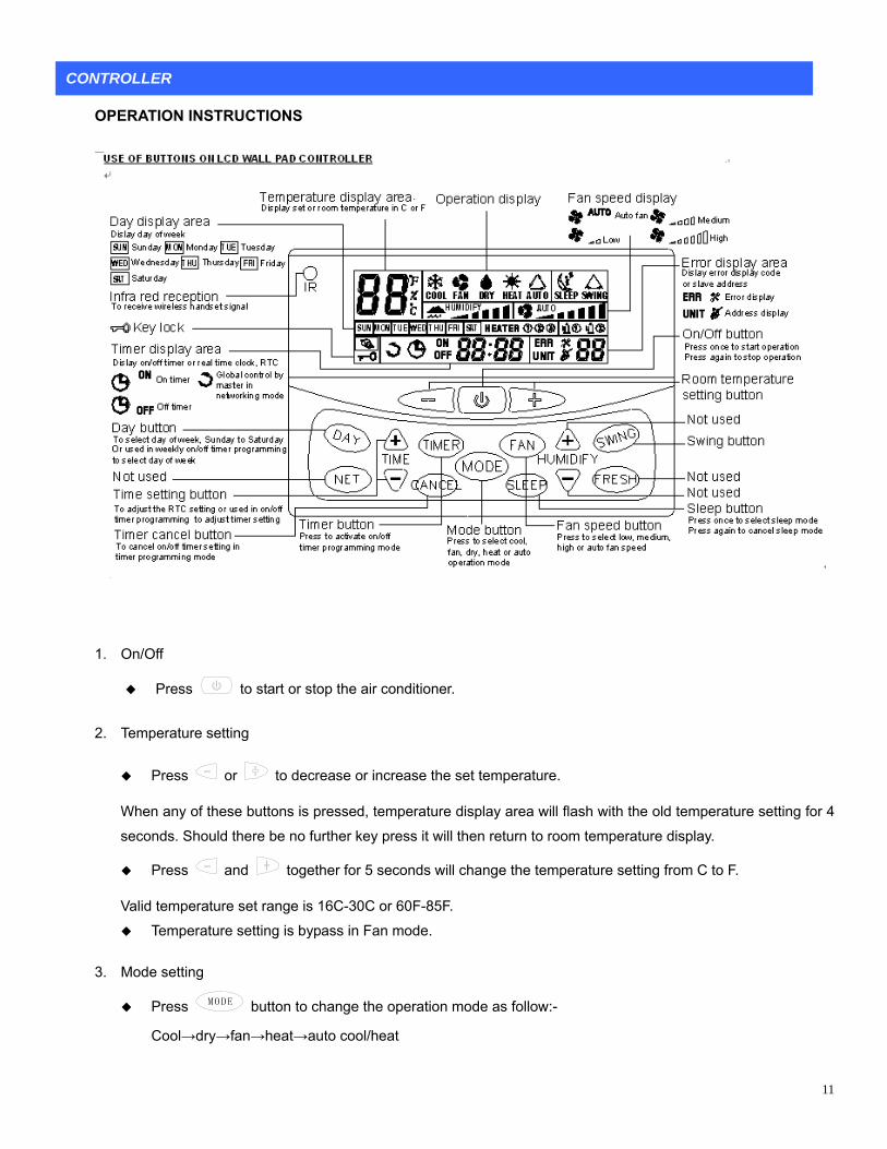
UCTIONS
1. On/
Press
CONTROLLER
OPERATION INSTR
Off
to start or stop the air er.
2 ture g
Press
condition
. Tempera settin
or to dec are se or increase
When any o essed, temperatu
be no further key press it will th eturn t
the set temperature.
f these buttons is pr re display area will rature setting for 4 flash with the old tempe
seconds. Should there en r o r temper e display.oom atur
Press and together for 5 nds w th tur o
et range is 16C-30C or 60F-85F.
Press
seco ill change e tempera e setting fr m C to F.
Valid temperature s
Temperature setting is bypass in Fan mode.
3. Mode setting
MODE button to change the operation mode as follow:-
Cool→dry→fan→heat→auto cool/heat

12
. Fan speed setting
Press
4
FAN button to change the fan speed:Auto→Low→Medium→High. Auto fan setting is bypass in Fan mode. Fan speed setting is bypass in dry mode.
5. Sleep setting
Press SLEEP button to activate or deactivate sleep setting. Sleep is bypass in Fan and Dry mode.
6. Swing setting
Press button to activate or deactivate swing setting. The availability of this function depends on the model of main board.
7. Fresh air
For main board with fresh air function, symbol will light up automatically. Sleep and dry mode is not available for this model.
8. Clock setting
Press
TIME
or TIME button to change the real time clock [RTC] setting.
Press
TIME
or TIME button will activate the clock programming mode, clock symbol flashes.
Subsequent press of
TIME
or TIME button will increase or decrease the current setting in 1 minute. Holding
down the button will change the current setting in a faster speed.
ek setting 9. Day of we
Press DAY
button to change current day of week from Sunday to Saturday.
10. On timer setting
Press TIMER button to select on timer or off timer programming mode. When on timer programming mode is selected, ON symbol and day of week flashing.
DAY Flashing of day of week indicates the on timer selected for this day. Press button to
day the on timer to be programmed. change the
a shows If on timer for this day is empty, timer display are , otherwise the on timer setting will be shown.
TIME
TIME Press or button to change the on timer setting. Holding down the button will change the setting
in a faster speed.
lights up indicating there is timer being programmed.
ressP CANCEL key to cancel the current on timer selected and the timer display area shows .
hould there be no further key press, system will exit from on timer programming mode 6 seconds later. S

11. Off timer setting
Press TIMER button to select on timer or off timer programming mode. When off timer programming mode symbol and day of week flashing. OFF is selected,
DAY Flashing of day of week indicates the on timer selected for this day. Press button to chan
day the off timer to be programmed. ge the
or this day is empty, timer display area shows If off timer f , otherwise the off timer setting will be shown.
TIME
TIME bu Press or tton to change the off timer setting. Holding down the button will change the setting
ter speed. in a fas
lights up indicating there is timer being programmed.
CANCEL key to cancel the current off timer selected and the timer display area shows . Press
Should there be no further key press, system will exit from on timer programming mode 6 seconds later.
12. Cancel all timer setting
In non on or off timer programming mode, hold down CANCEL key for 5 seconds will cancel all the on or off
timer being programmed.
This function can be activated in fan or heat mode only. The availability of this function depends on the
13. Hot water coil
model of main board.
13
Press and MODE to activate hot water coil function, symbol HEATER will light up. Repeat the same
function.
Press
step to exit this
or to decrease or increase the set temperature.
14. Coil temperature display
and FAN Hold down buttons to activate coil temperature display function. Timer display area will
show the coil temperature selected in the range of –33C to 78C while temperature display area shows the
selection of either indoor coil or outdoor coil temperature to be displayed. Repeat the same sequence to
cancel coil temperature display function.
Press or to select either indoor coil or outdoor coil temperature to be displayed. C1 will be shown
when indoor coil temperature display is selected. C2 will be shown when outdoor coil temperature display is
selected.
For dual stage system, press MODE to select the data of the system to be display. Symbol will be
shown for #1 system and for #2 system.

15. Key lock
In order to prevent unauthorized access to the system setting, a key lock function is provided to prevent
14
mischief.
When the system is on, hold down MODE and buttons for 3 seconds to activate the key lock function,
will light up. Repeat the same sequence to cancel key lock function. key lock symbol
Only button press is acknowledged.
board.
ly.
16. Time shortening
This function is to activate the time shortening program in the main
It must be used with care and is recommended for PCB testing on
This function can only be activated within first 1 minute after system is powered on.
Hold down and buttons to activate this function.
17. Main board parameter editing
ctivated when system is in standby mode.
Hold down
This function is used to edit the defrost and heat mode parameters for the main board.
This function can only be a
and TIMER buttons to activate this function. Temperature display area shows “EP”
assword entry at timer and error display area. Timer and error display area shows “0000” requesting for p
initially with first digit stand still while the remaining 3 digits flashing. This indicates the first digit password
entry. Press or to edit the numerical input from “0” to “9”. Upon completion of editing the number,
press to confirm the entry of this digit and this digit will then mask with “-“. The next available digit will
then be replaced by the number just entered, i.e. if the first digit is “8”, it will be displayed as“-800”. Second
he second digit password entry. Follow
the same arguments above to complete the password entry for these four digits. The password to enter into
e is “8699”.
d.
digit stand still and the remaining 2 digits flashing. This indicates t
parameter editing mod
If password entry is correct, system will respond with a beep sound. If password is wrongly entered 3 times
consecutively or 60 seconds for password entry times up, system will exit from this mode automatically and
user needs to repeat the complete process in order to access this function.
Upon successful of password entry, temperature display area shows the submenu selection and timer
display area shows the value of parameter to be edite
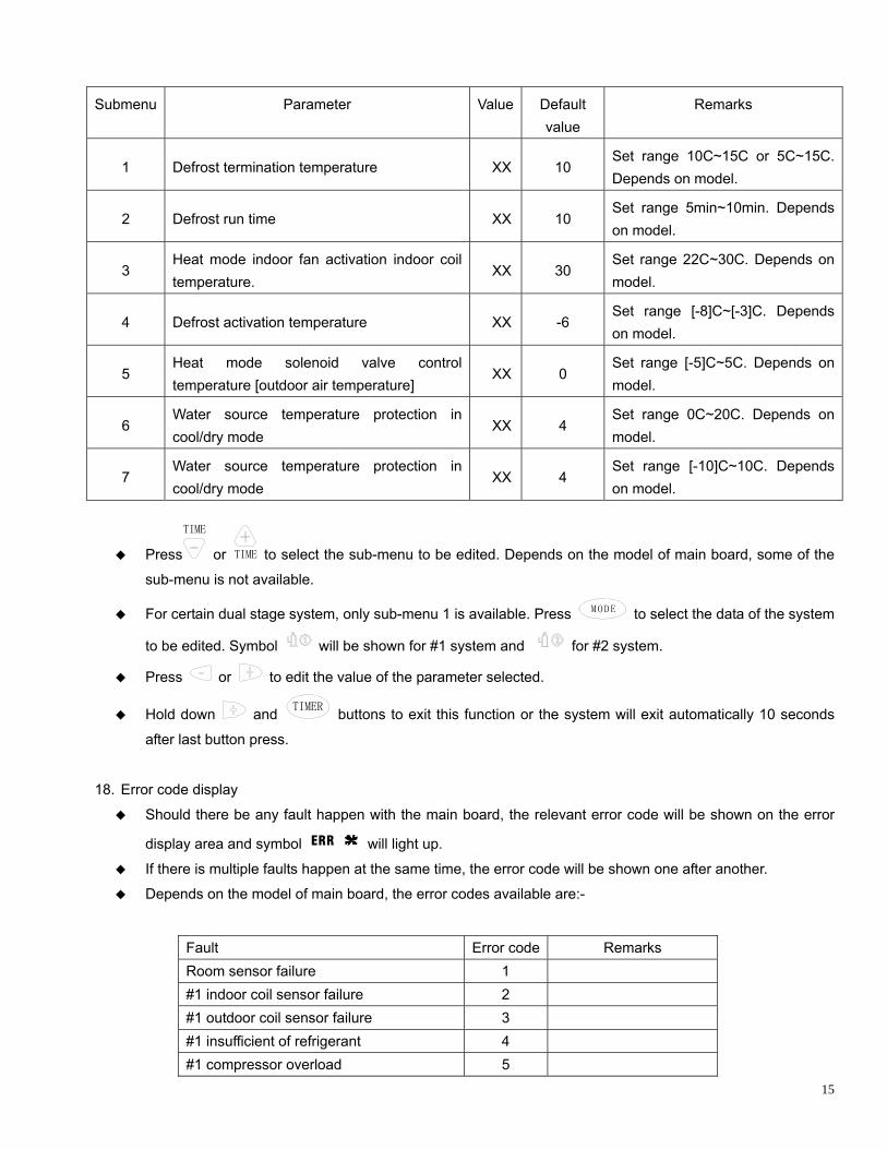
Submenu Parameter Value Default Remarks
15
value
1 Defrost termination temperature XX 10 Set range 10C~15C or 5C~15C. Depends on model.
XX 10 Set range 5min~10min. Depends on model.
2 Defrost run time
3 Heat mode indoor fan activation indoor coil
XX 30 Set range 22C~30C. Depends on
odel. temperature. m
Set range [-8]C~[-3]C. Depends 4 Defrost activation temperature XX -6
on model.
5 Heat mode solenoid valve control
XXtemperature [outdoor air temperature]
0 Set range [-5]C~5C. Depends on model.
6 Water source temperature protection in
XX 4 Set range 0C~20C. Depends on
cool/dry mode model.
7 Water source temperature protection in
XX 4 cool/dry mode
Set range [-10]C~10C. Depends on model.
Press
TIME
or TIME to select the sub-menu to be edited. Depends on the model of main board, some of the
sub-menu is not available.
For certain dual stage system, only sub-menu 1 is available. Press MODE to select the data of the system
to be edited. Symbol will be shown for #1 system and for #2 system.
Press or to edit the value of the parameter selected.
Hold down and TIMER buttons to exit this function or the system will exit automatically 10 seconds
after last button press.
18. Error code display
Should there be any fault happen with the main board, the relevant error code will be shown on the error
display area and symbol ERR will light up.
If there is multiple faults happen at the same time, the error code will be shown one after another.
Depends on the model of main board, the error codes available are:-
Fault Error code Remarks Room sensor failure 1 #1 indoor coil sensor failure 2 #1 outdoor coil sensor failure 3 #1 insufficient of refrigerant 4 #1 compressor overload 5

16
#1 low pressur e failure 6 #1 high pressure failure 7 Water source temperature protection 8 Water source heatpump #2 indoor coil sensor failure 9 #2 outdoor coil sensor failure 10 #2 insufficient of refrigerant 11 #2 compressor overload 12 #2 low pressure failure 13 #2 high pressure failure 14 Communication failure 15 #1 indoor anti freeze 16 #2 indoor anti freeze 17 Prevent heatpump function in low ambient 18 Flow switch failure 19 Condensate water drainage failure 20
19. Defrost
Symbol HEAT flashes when system enter into outdoor defrost.
The system is able to receive the infra-red wireless commands from LCD handset or non LCD handset.
nal reception.
It beeps twice when the system is turned on, otherwise beeps once to all other valid acknowledgement
Back light colour changes according to the operating mode setting.
ode Backlight Colour
20. Infra red signal reception
21. Buzzer
Buzzer beeps in responding to valid button press or wireless sig
22. Backlight
Operating M
Cool Blue
Fan Yellow
Dry Pink
Heat Reddish orange
Auto Light violet
The c ill change to red whenever there is sy heneve cleared, backlight colour
will re
If the unit is on, backlight will turn off 30 seconds after the last button press.
If the turn on the backli screen di play. The backlight will turn off
10 seco
olour w stem fault. W r the fault is
turn to original.
unit is off, any button press will ght and the s
nds after last button press.

17
23. Master-sla
If the eway card, a master controller can control it.
The a ard will be shown he error display area with symbol
ve
wall pad is connected to a gat
ddress setting of the gateway c on t UNIT lights
up. Th eplace by error sym display if there is any fault happen to the main
board ared, it will return to ga y address displa
If the ing in global control mode, symbol
is symbol will turn off and r bol
. Whenever the fault is cle tewa y.
master controller is work ts up. None of the button or
infra-r owledged until master controller give up glob control mode.
24. Battery
A batt ternal real time clock when the power supply is cut off.
The in ery is shown as follow:
locking
gh
ed reception will be ackn al
ery is used to sustain the operation of the in
stallation of the batt
Use screw driver to remove thescrew
Remove the back cover
CR2032
Slide the battery in and take note the polarity
18
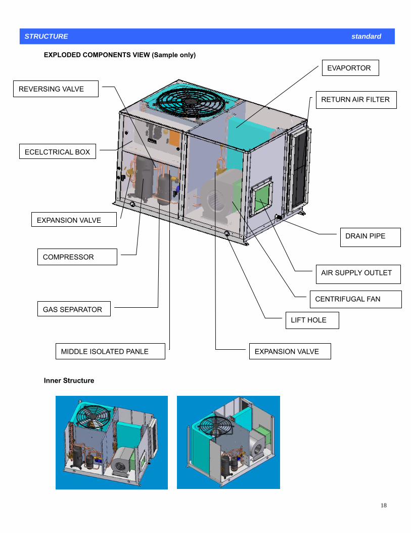
STRUCTURE standard
EXPLODED COMPONENTS VIEW (Sample only)
EVAPORTOR
REVERSING VALVE RETURN AIR FILTER
ECELCTRICAL BOX
MIDDLE ISOLATED PANLE
GAS SEPARATOR
AIR SUPPLY OUTLET
CENTRIFUGAL FAN
LIFT HOLE
EXPANSION VALVE
DRAIN PIPE
COMPRESSOR
EXPANSION VALVE
Inner Structure

19
CAAHP10 12
F
EC
HI
G
K
D
AB
L
DIME
Dimension Code Dimension
NSION
Code
A 541.5 G 795
B 260 H 300
C 895 I 439
D 855 J 90
E 1040 K 40
F 1190 L 1280
Note: 1, Unit fixed
CAAHP14-32
hole 4 × φ12.5 2, Unit single hole 4 × φ50 3, Unit electric control panel 4, Unit power cable entry φ22
gnal wire holeφ16 6, Unit condensing water discharge pipe 3/4” 5, Unit si
P
Q
Note: 1, Unit fixed hole 4 × φ12.5 2, Unit single hole 4 × φ50 3, Unit electric control panel 4, Un5, Unit signal wire holeφ16 6, Unit condensing water discharge 3/4”
CAAHP17,20 CAAHP22,25 CAAHP28 CAAHP30/32
it power cable entry φ22
MODEL CAAHP14
A 1610 1730 1900 2200 2200
B 1130 1230 1100 1400 1400
C 286 286 345 345 409
D 262 262 268 268 318
E 1040 1390 1390 1390 1390
F 113 190 118 118 118
G 298 298 330 330 330
H 701 825 787 786.5 786.5
M 280 423 495 507 495
L 1670 1780 1940 2240 2240
J 1045 1050 1045 1045 1045
N 91 110 150 120 150
P 795 843 795 780 795
Q 1005 1008 1005 1005 1005
20
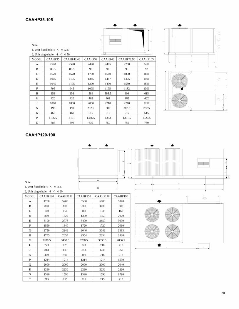
AAHP35-105
CAAHP12
C
0-190
Note: 1, Unit fixed hole 4 × φ12.5 2, Unit single hole 4 × φ50
MODEL CAAHP35 CAAHP42,48 CAAHP52 CAAHP63 CAAHP72,90 CAAHP105
A 2540 2540 2490 2495 2750 3410
B 86.5 86.5 90 90 90 92
C 1620 1620 1700 1660 1800 1600
D 5 5 1447 1465 1590 100 11 5 1345
E 1045 1195 1490 1550 1810 1390
F 795 945 1195 1182 1300 1095
H 8 358 595.5 609 615 35 589
M 0 420 462 462 462 42 462
J 860 1860 2210 2210 2210 1 2050
N 199 199 309 307.5 282.5 237.5
K 0 460 615 615 615 615 46
P 1336.5 1353 1331.5 1326.5 1166.5 1161
U 630 750 750 750 585 596
R
Q
P
S
T
Note: 1, Unit fixed hole 42, Unit single hole
MODEL CAAHP120
× φ16.5 4 × φ60
CAAHP130 CAAHP150 CAAHP170 CAAHP190
A 4700 5200 5500 5800 5870
B 800 800 800 800 800
C 160 160 160 160 160
D 800 1622 1300 1350 2070
E 3100 2778 3400 3650 3000
F 1590 1640 1720 1720 2010
G 2750 2846 3046 3046 3383
H 1755 2054 2354 2654 2300
M 3288.5 3438.5 3788.5 3938.5 4036.5
L 723 723 723 718 718
J 813 813 813 650 650
N 400 400 400 718 718
P 1214 1214 1214 1214 1500
Q 2000 2000 2000 2000 2040
R 2230 2230 2230 2230 2230
S 1590 1590 1590 1590 1790
T 215 215 215 215 215

21
INSTALLATION AND MAINTENANCE PREFACE ● CKING Ret until the unit is operated and found to be in good condition. If the unit shows external or inte ot operate properly, contact the transportation company and file a damage claim. ● AFTER-SA SUPPORT BRIGHT is co tted to tomer ice b uring after the sale. If you have questions concerning the opera n of y nit or inform of th oklet, act our Sales Department. If your units fail to operate properly, or if y have qu ions co ning arts ervice act, contact our Sales Department. SECTION I: SAFETY These instruc are p rily in d to st qua individuals experienced in the proper installation of heatin and/o conditi g appli s. Some local co require licensed installation/service personnel for this
l insta ns m ce hese ctions and with all applicable national and cal codes and standarde recommend that you read this instruction manual carefully before use to gain full advantage of the functions of e unit and to avoid malfunction due to mishandling.
ctions thoroughly before starting the installation. Follow all precautions and warnings contained within these instructions and on the unit. 1. SAFETY CONSIDERATIONS The unit is designed to provide safe and reliable service when operating within design specifications. To avoid injury to personnel and damage to equipment or property when operating the equipment, the following safe practices should be observed as a minimum.
Check the unit weight to be sure the lifting equipment is adequate. ct p r to the unit before working on it.
cess panels or doors until fans have completely stopped. o a th ile the fan is running.
● Protect material en we or flame cutting suitable cloth to contain sparks. Have a fire extinguisher at hand and ready for immediate use.
2. WARNI nd CA ON The precautio scrib below WARNING and N. These are very important precautions c ernin ty. Be sure to o all o wit il.
INSTALLATION AND MAINTENANCE
UNPAain packing materials rnal damage, or does n
LESmmi cus serv oth d and
tio our u the ation is bo contou est ncer spare p or S Cont
tions rima tende assi lifiedg r air onin ance des
type equipment. Al llatio ust be in accordan with t instrulo s. WthRead these instru
Disconne owe Do not remove ac D not enter n enclosed fan cabinet or into e unit wh s wh lding . Use
NG a UTIns de ed are CAUTIO
onc g safe bserve f them hout fa
WAR G
matte ith possibilities le g to s s con ences such as death or serious injury due to erroneous a ling.
NIN
The rs w adin eriou sequh nd
CAUTION
hese are the matters with possibilities leading to injury or material damage due to erroneous handling including ces in some cases.
nd servicing of air conditioning equipment can be hazardous due to system pressure and electrical trained and qualified service personnel should install, repair or service air conditioning equipment.
ment, bserve precautions in the literature, tags and labels attached to the unit and other safety precautions that may
nit: erformance of installation, operation, or maintenance procedures other than those described in this manual may
ation and may void the manufacturer's warranty.
labels.
rd from the power source before performing any service or
ged power cords. Refer service and repairs to a qualified technician.
erant.
unit model number is printed on
harge Adjustment
s stated previously, the system is pre-charged. If further charge is required to be added, this can be done by refrigerant only through the compressor suction pipe valve.
All must be carried out by a qualified and licensed electrician. The installation must comply with the curre tandards wiring rules and local authority requirements. Wire sizing is the responsibility of the
specification of the unit for the electrical data. The electrical installation requirements are generally as e air-conditioning unit shall be supplied directly from a distribution board through a mains lockable
olating switch.
Tprobabilities leading to serious consequenInstallation acomponents. Only Untrained personnel can perform basic maintenance functions of cleaning coils and filters and replacing filters. All other operations should be performed by trained service personnel. When working on air conditioning equipoapply. 3. ADDITIONAL WARNINGS In addition to the specific warnings listed on the previous page the following general warnings apply to your uPresult in a hazardous situTransport the unit with care. Sudden jolts or drops can damage the refrigeration lines.
Observe all warning labels. Never remove warning Never operate damaged or leaking equipment. Always turn off the unit and disconnect the power co
maintenance procedures, or before moving the unit. Never operate equipment with dama
Do not overcharge with refrig
SECTION II INSTALLATION
1) INSTALLATION REQUIREMENTS
EQUIPMENT APPLICATION
Before beginning the installation, verify that the unit model is correct for the job. Thethe data label.
C
ACAREFULLY drawing LIQUID
ELECTRICAL
electrical worknt relevant s
installer, as it depends on the conditions and regulations applicable to each installation site. Refer to the electrical drawing and follows: This
22
23
Pre punched holes have been provided in the unit casing for the isolating switch. Do not drill into the cabinet as pipe ted behind.
ing the length of the supply ducts. Consideration should also be given to availability, service access, noise, all avoid areas where condensate drainage may cause problems.
the unit. This unit is supplied with air filters. Air filter(s) must be installed
UNIT INSTALLATION
ing foundation. The pad ensure proper condensate disposal and strong enough to support the unit’s weight.
UNCONDITIONED SPACES
r cable slings to the holes provided in lifting lugs. Spreaders MUST be used across the top of the
s may be loca
REQUIREMENTS AND CODES The unit should be installed in accordance with all national and local codes and regulations which govern the installation of this type of equipment. In lieu of local codes, the equipment should be installed in accordance with National Electric Code, and in accordance with the recommendations made by the National Board of Fire Underwriters. UNIT LOCATION The electric unit is designed only for outdoor installations. Choosing the location of the unit should be based on minimizand shade. The unit installation shCLEARANCES The units require certain clearances for proper operation and service. Installer must make provisions for adequate ventilation air, normally 2000mm’s spaces all around the units. It’s required to place a anti wind/rain hood 2000mm above the unit.
AIR FILTER REQUIREMENT A suitable air filter must be installed in ahea of the evaporator coil of this unit.
d
GROUND LEVEL If installing the unit at ground level, provide a concrete mounting pad separate from the buildmust be level to
All ductwork passing through unconditioned spaces must be properly insulated to minimize duct losses and prevent condensation. Refer to local codes for any insulation material requirements. RIGGING AND HOISTING This unit is not designed to be handled with a fork-truck Exercise care when moving the unit. Rig the unit by attaching chain o
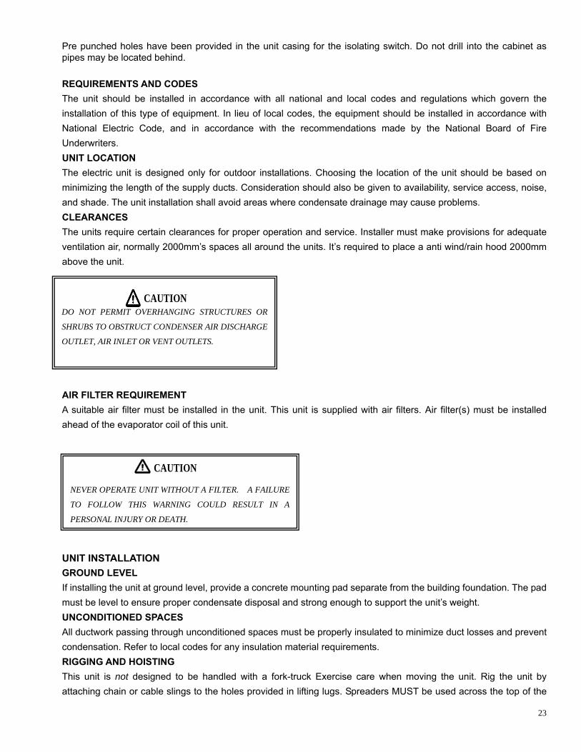
DO NOT PERMIT OVERHANGING STRCAUTION
UCTURES OR
SHRUBS TO OBSTRUCT CONDENSER AIR DISCHARGE
OUTLET, AIR INLET OR VENT OUTLETS.
CAUTION
NEVER OPERATE UNIT WITHOUT A FILTER. A FAILURE
URY OR DEATH. TO FOLLOW THIS WARNING COULD RESULT IN A
PERSONAL INJ
24
the units center of gravity. Lifting plates may be removed after installation.
The unit should be a firm flat horizontal base plinth using the holes supplied in the mounting rails. mended that the unit is installed on a substantial structure with
se springs are not supplied with the unit. Three channels are ounts or bolting down.
lexible duct connections are recommended between the supply and return ducts and the unit.
required to allow the crankcase heaters to drive any liquid refrigerant out of the compressor oil. . Check that the shipping blocks beneath each compressor have been removed and that each compressor is
ecure on its mount. Check that all fan motors a running.
nit and is set at the desired temperature. d if fitted.
.
E
in delay timer.
n power terminal.
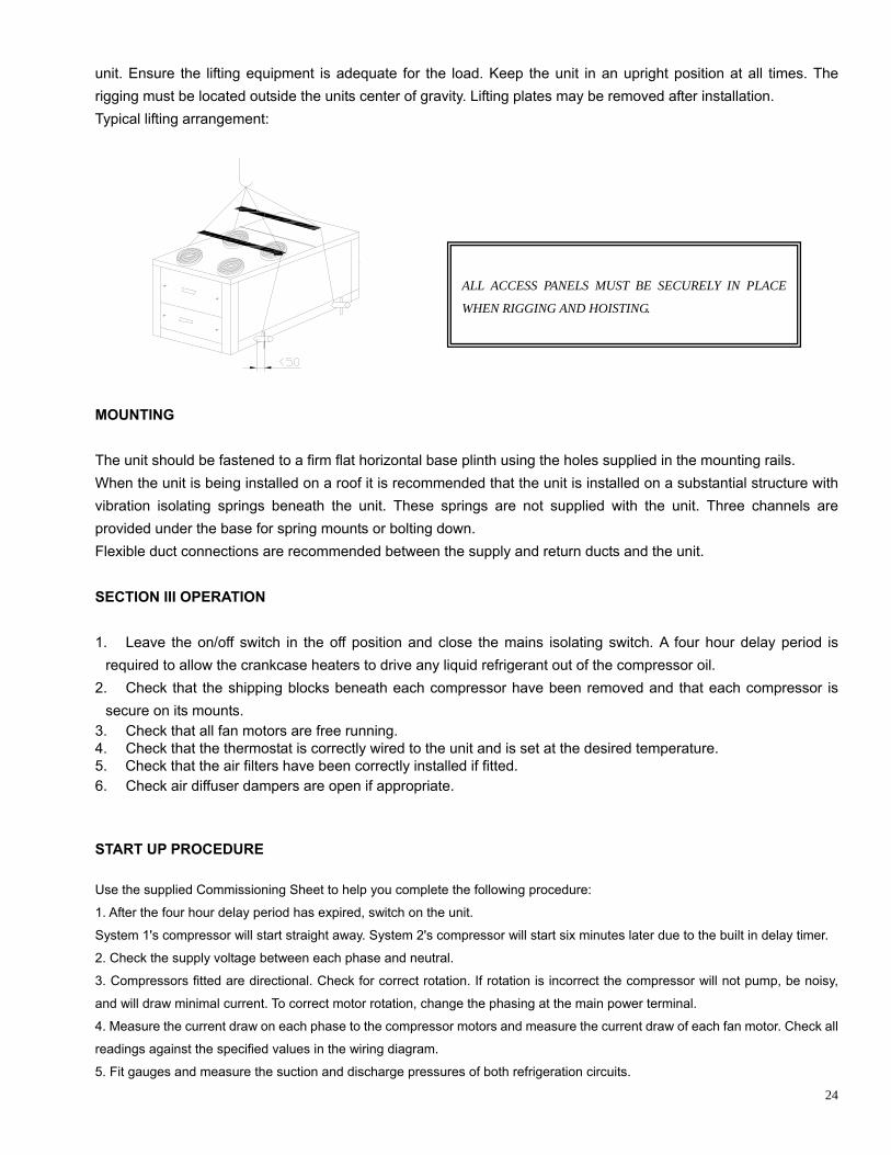
unit. Ensure the lifting equipment is adequate for the load. Keep the unit in an upright position at all times. The rigging must be located outsideTypical lifting arrangement: MOUNTING
fastened to When the unit is being installed on a roof it is recomvibration isolating springs beneath the unit. Theprovided under the base for spring mF SECTION III OPERATION 1. Leave the on/off switch in the off position and close the mains isolating switch. A four hour delay period is
2s s.
re free 34. Check that the thermostat is correctly wired to the u
. Check that the air filters have been correctly installe Check air diffuser dampers are open if appropriate.
56
START UP PROCEDUR
Use the supplied Commissioning Sheet to help you complete the following procedure:
1. After the four hour delay period has expired, switch on the unit.
System 1's compressor will start straight away. System 2's compressor will start six minutes later due to the built
2. Check the supply voltage between each phase and neutral.
3. Compressors fitted are directional. Check for correct rotation. If rotation is incorrect the compressor will not pump, be noisy,
To correct motor rotation, change the phasing at the maiand will draw minimal current.
4. Measure the current draw on each phase to the compressor motors and measure the current draw of each fan motor. Check all
readings against the specified values in the wiring diagram.
5. Fit gauges and measure the suction and discharge pressures of both refrigeration circuits.
ALL ACCESS PANELS MUST BE SECURELY IN PLACE
WHEN RIGGING AND HOISTING.

6. Check that the outdoor air fan motors are running smoothly.
7. Test the operation of the reversing valve by running the unit in both the heating and cooling mode.
8. Check the indoor unit's fan belt tension after 20 mins of operation and adjust if necessary (refer
ommissioning Sheet).
. Check the supply air flow at each outlet.
0. Check the tightness of all electrical connections and sign the check label.
. Touch up any outdoor unit paintwork damage to prevent corrosion.
2. Running the unit in both the heating and cooling mode.
C
9
1
11
1
THE UNIT IS EQUIPPED WITH CRANKCASE HEATERS. A
UP PROCEDURES TO ALLOW FOR HEATING OF TH R CRANKCASE.
FAILURE TO COMPLY MAY RESULT IN DAMAGE AND COULD CASUE PREMATURE OF THE SYSTEM. THIS
WARNING SHOULD BE FOLLOWED AT INITIAL START UP AND ANY TIME THE POWER HAS BEEN
REMOVED FOR 12 HOURS OR LONGER.
LLOW 24 HOURS PRIOR TO CONTINUING START
E REFRIGERANT COMPRESSO
25

SECTION IV MAINTENANCE
t failure,
d be
t once each year by a qualified service person. The minimum maintenance
follows:
To ensure continuing high performance, and to minimize the possibility of premature equipmen
periodic maintenance must be performed on the air conditioning equipment. The units shoul
inspected at leas
requirements for this equipment are as
MAINTENANCE TIME SCHEDULE
Monthly 4. Check for excessive noise and
y. vibration and correct as necessar
1. Check air filters, Replace
throwaway type filters when they
become logged with dust and lint or
clean cleanable type filters monthly.
3. Check suction and discharge
operating pressures.
5. Check fan and motor bea
and lubricate or replace
rings
as
necessary.
2. Check condensate drain for free
drainage. 4. Replace indoor air filters (if fitted).
6. Check for insulation and duct
damage and repair as necessary.
3. Check compressor compartment
for oil stains indicating refrigerant
leaks.
5. Check condensate drain for free
drainage.
7. Remove lint and dust
accumulation from outdoor coil fins.
Three Monthly (or every 1200 hrs of operation)
8. Touch up any paintwork damage
to prevent corrosion.
Check the indoor unit's fan belt
tension and adjust if necessary. Yearly
Inspect outdoor coil. Clean when
necessary.
Six Monthly 1. Check all refrigerant piping for
chafing and vibration.
Ensure that fan blades are clean and
adequately balanced.
1. Check the tightness of electrical
connections.
2. Check the operation of electric
heaters, if fitted.
Check refrigerant charge by
measurement of superheat and sub
cooling where necessary, adjust
charge and TX valve to achieve
optimum performance.
2. Check the tightness of all fans,
motor mountings, pulleys and belt
tension.
3. Check air supply at all diffusers. Check the tightness of electrical
connections.
26
Recommended