Roll Density Tester
Model RDT-2000B
Operating Instructions
Kershaw Instrumentation Inc.517 Auburn Ave.Swedesboro New Jersey08085USA
p. 856-467-5482f. 856-467-2341

Table of Contents
1.0 Introduction
2.0 Operation
3.0 Force Calibration
4.0 Displacement Calibration
5.0 Calibration check using the Calibration Spring Carrousel.

1.0 INTRODUCTION
The Roll Density Tester Model RDT-2000 is a fully automatic Laboratory
test instrument designed to measure the roll firmness of consumer rolls. The
tester consists of a motor driven table, a load cell assembly the measures
the force exerted on the roll and a displacement sensor that measures the
probe penetration. Digital meters display the test parameters. An optional
RS232 interface allows the operator to interface this instrument to a P.C.
2.0 OPERATION
2.1 Turn the instrument on and allow it to warm up for about 15 minutes.
2.2 Move the Run/Calibrate toggle switch to the RUN position.
2.3 Install the roll to be tested onto the test spindle.
2.4 Adjust the roll diameter assembly until the pointer indicates the
nominal diameter of the roll being tested.
2.5 Press the “ Green” forward button, the table will automatically move
toward the roll to be tested. Once the probe contacts the roll, the force exerted
on the probe will be displayed on the digital force display. When the probe
contacts the roll, a set point in the force meter (low set point) will command the
displacement circuit to begin measuring the probe penetration. The table will
continue to move toward the spindle thus increasing the penetration of the
probe into the roll and increasing the force on the probe. Once the probe force
gets high enough a 2nd set point in the force meter (high set point) will
command the displacement to stop measuring the probe penetration, stop the
motor, hold the displacement value (probe penetration) on the digital
displacement meter, then return the motorize table back to its home position,
hence completing the test. The displacement value will remain on the digital
displacement meter until the beginning of the next test.

3.0 LOAD CELL CALIBRATION 3.1 Move the run/calibrate switch to the calibrate position.
3.2 Remove the 2 socket head cap screws that attach the load cell assembly
to the table. Remove the load cell assembly from the machine and stand the
load cell with no weight applied on end as shown in figure 1 below.
Figure 1
3.3 Depress the ´ button on the front of the force display as shown in Figure
2. The display will read Lo In (low input) .
Figure 2

3.4 Depress the < button on the front of the force display as shown in Figure
3. A numerical value will soon appear.
Figure 3
3.5 After the numerical value appears, press the > button on the front of the
force meter as shown in figure 4. Soon the word store will appear hence storing
this calibration value.
Figure 4

3.6 Apply a 1000 gram calibration weight to the load cell as shown in figure 5.
Figure 5
3.7 Depress the ´ button on the front of the force display as shown in Figure
6. The display will read Hi In (high input) .
Figure 6
3.8 Repeat steps 3.4 and 3.5 to store this 1000 gram calibration value.
3.9 Depress the ´ button on the front of the force display as shown in Figure
6 several times until the word “Reset” appears. This process will “store” all of the
calibration values and return the display to the operational mode.

4.0 DISPLACEMENT CALIBRATION
4.1 Move the run/calibrate switch to the calibrate position.
4.2 Disconnect the motor driven table from the lead screw by pressing down
and rotating the knurled knob 1/4 turn CCW as shown in the Figure 7. This will
allow you to move the motor drive table freely by hand.
Figure 7
4.3 Move the table to the 0.0 step on the calibration step fixture as shown in
Figure 8.
Figure 8
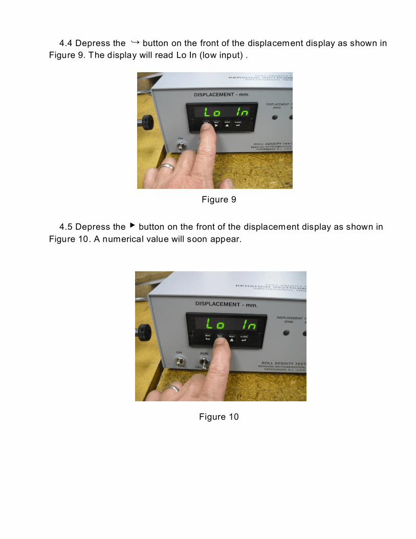
4.4 Depress the ´ button on the front of the displacement display as shown in
Figure 9. The display will read Lo In (low input) .
Figure 9
4.5 Depress the < button on the front of the displacement display as shown in
Figure 10. A numerical value will soon appear.
Figure 10

4.6 After the numerical value appears, press the > button on the front of the
displacement meter as shown in figure 11. Soon the word “store” will appear
hence storing this calibration value.
Figure 11
4.7 Next move the table to the 12.5 step on the calibration step fixture as
shown in Figure 12.
Figure 12
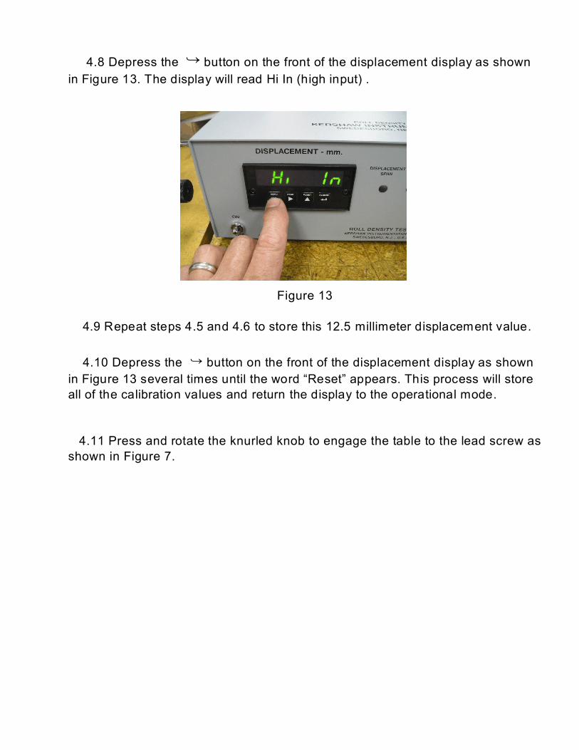
4.8 Depress the ´ button on the front of the displacement display as shown
in Figure 13. The display will read Hi In (high input) .
Figure 13
4.9 Repeat steps 4.5 and 4.6 to store this 12.5 millimeter displacement value.
4.10 Depress the ´ button on the front of the displacement display as shown
in Figure 13 several times until the word “Reset” appears. This process will store
all of the calibration values and return the display to the operational mode.
4.11 Press and rotate the knurled knob to engage the table to the lead screw as
shown in Figure 7.
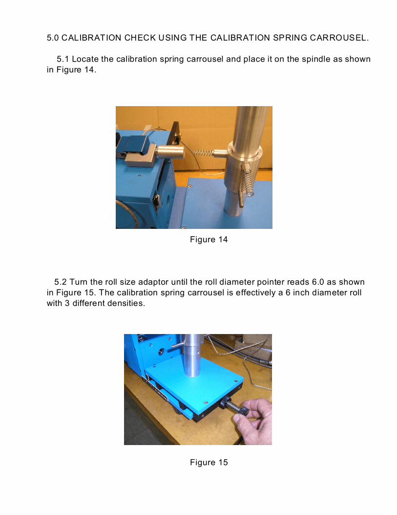
5.0 CALIBRATION CHECK USING THE CALIBRATION SPRING CARROUSEL.
5.1 Locate the calibration spring carrousel and place it on the spindle as shown
in Figure 14.
Figure 14
5.2 Turn the roll size adaptor until the roll diameter pointer reads 6.0 as shown
in Figure 15. The calibration spring carrousel is effectively a 6 inch diameter roll
with 3 different densities.
Figure 15

5.3 Move the run/calibrate switch to the run position.
5.4 Press the green forward button to run a test using the calibration spring.
Run several tests on each spring to check the calibration and repeatability. The
test numbers should match the numbers shown in the table below.
Short Spring 1.5 - 2.0 Millimeters
Medium Spring 2.6 - 3.2 Millimeters
Long Spring 3.9 - 4.5 Millimeters
Recommended