Robustness Assessment of a Steel Truss Bridge
P. Olmati1, F. Brando2 and K. Gkoumas1
1School of Engineering, Sapienza University of Rome, Via Eudossiana 18, 00184, Rome, Italy; PH +39-06-44585.265; FAX +39-02-30136014; email: [email protected]; [email protected] 2Thornton Tomasetti, 51 Madison Ave, New York, ST 10010-1603; PH (917) 661-7800; FAX (917) 661-7801; email: [email protected] ABSTRACT
This study focuses on the robustness assessment of a steel truss bridge. In the first part, a brief overview of several robustness indexes found in literature is provided, together with the principal approaches on the topics of structural robustness, collapse resistance and progressive collapse. In the second part, the extensively studied I-35W Minneapolis steel truss bridge is used as a case study for the application of a consequence-based robustness assessment. In particular, focus is given on the influence that the loss of primary elements has on the structural load bearing capacity. INTRODUCTION
Structural robustness is a research topic particularly relevant in the design and the safety assessment of both new and existing structures. The latter are prone not only to local failure due to accidental or man-made attacks, but also due to long term material degradation (e.g. corrosion), bad design or construction. Behind this attention, there is the increasing interest from society that cannot tolerate death and losses as in the past. This is more evident after:
· recent terrorist attacks (a series of terror attacks in America and beyond, the deadliest being the September 11, 2001 attacks);
· recent bridge collapses due to deterioration or bad design or bad construction (for example, the De la Concorde overpass collapse in Montreal, 2006).
· recent multiple hazard events from natural sources the most significant of which was the 2011 earthquake, off the Pacific coast of Tōhoku. Steel truss bridges in particular, in their various forms, very common
worldwide, are now aged, not often optimally maintained, and need to be checked both for safety and serviceability.
Considering what said above, aim of this paper is to apply to a steel truss bridge, a methodology for the robustness assessment that, among else, takes into account the consequences of unexpected actions on or unforeseen events (England et al. 2008) on structures, with a special focus on the effect of the loss of primary elements on the structural load bearing capacity.
250Structures Congress 2013 © ASCE 2013

STRUCTURAL ROBUSTNESS AND PROGRESSIVE COLLAPSE
A variety of terms have been used in literature, however, typically robustness is defined as the “insensitivity of a structure to initial damage” and collapse resistance as the “insensitivity of a structure to abnormal events” (Starossek and Haberland, 2010). Similarly, ASCE 7-05 (2005), defines progressive collapse as the spread of an initial local failure from element to element, eventually resulting in collapse of an entire structure or a disproportionately large part of it. Starossek and Haberland (2010) focus on the differences of progressive and disproportionate collapse, concluding that the terms of disproportionate collapse and progressive collapse are often used interchangeably because disproportionate collapse often occurs in a progressive manner and progressive collapse can be disproportionate.
A review of international research on structural robustness and disproportionate collapse is provided in Arup (2011). Arangio et al. (2011) and Sgambi et al. (2012) provide a dependability framework adapted from the electronic engineering field, where dependability attributes are either related to structural safety or serviceability. Potential failure scenarios specific for bridges are provided in FHWA (2011), within a framework aiming at the resilience improvement. Giuliani (2012) identifies the design strategies for obtaining robustness, using prevention and mitigation measures. An additional aspect is the inherent uncertainty associated with actions and mechanical, geometric and environmental parameters cannot be ignored since they affect the structural response (Petrini and Ciampoli, 2012).
Structural robustness assessment methods. A relevant issue related to the structural robustness evaluation, is the choice of appropriate synthetic parameters describing for example the sensitivity of a damaged structure in suffering a disproportionate collapse.
Eurocode 1 (EN 1991-1-7 2006) merely outlines the issue of structural robustness in a qualitative manner, stating that a structure should not be damaged by events to an extent disproportionate to the original cause. Several authors provide a review of methods for assessing structural robustness (Canisius et al. 2007; Starossek and Haberland, 2010; COST, 2011; Sørensen et al. 2012; Parisi and Augenti 2012; Cavaco et al. 2013). In what follows a non-exhaustive overview of approaches for the robustness assessment is provided, focusing on the proposed indexes.
Ellingwood and Dusenberry (2005), link the progressive collapse probability P(F) to a chain of probabilities, consisting in (i) the hazard of an abnormal event P(H), (ii) the local damage as a consequence of this hazard P(D│H), and (iii) the failure of the structure as a result of the local damage D due to H P(F│DH).
P(F)= P(F│DH)·P(D│H)·P(H)
Baker et al. (2008) propose a probabilistic framework for the robustness
assessment, computing both direct risk, associated with the direct consequences of potential damages to the system, and indirect risk, corresponding to the increased risk of a damaged system. The latter corresponds to the robustness of the system, since it can be assumed as a risk from consequences disproportionate to the cause of
251Structures Congress 2013 © ASCE 2013
the damage. In their approach, a robust system is considered to be one where indirect risks do not contribute significantly to the total system risk.
IndDir
DirRob RR
RI
+=
The index takes values from 0 (if all risk is due to indirect consequences) to 1 (if there is no risk due to indirect consequences, thus, the system is completely robust).
Biondini and Restelli (2008) propose a robustness index (ρ) associated with the displacements of the system:
d
o
s
s=ρ
Where s0 is the displacement vector, ║·║ denotes the Euclidian norm, and the
subscript “0” and “d” refer respectivelly to the intact and damage state of the
structure.
Izzuddin et al. (2008) propose a multi-level framework for the progressive collapse assessment of building structures subject to sudden column loss. The proposed assessment framework utilizes three main stages: (i) nonlinear static response of the damaged structure under gravity loading; (ii) simplified dynamic assessment to establish the maximum dynamic response under sudden column loss; and, (iii) ductility assessment of the connections. Within this framework, they propose that the single measure of structural robustness is the system pseudo-static capacity, that is the maximum value of the nonlinear static resistance for which the resulting maximum dynamic displacement, is less than or equal to the ductility limit. The comparison of the latter against the applied gravity loading establishes the required limit state.
Cavaco et al. (2013) consider robustness as the measure of degree of structural performance lost after damage occurrence, and propose the following metric (Rd: Robustness Index).
∫=
==
1
0)(
d
dd dxxfR
Where Rd indicates the area above the curve defined by the normalized structural performance f (given by the ratio between the structural performance on the intact and damage states), subjected to a normalized damage d (given by the ratio between actual and maximum possible damage).
Nafday (2011) discusses the usefulness of consequence event design, for extremely rare, unforeseen, and difficult to characterize statistically events (black swans). In this view, the author, with reference to truss structures, proposes an
252Structures Congress 2013 © ASCE 2013
additional design phase that focuses on the robustness, the damage tolerance and the redundancy of the structure. This proposed metric consequence factor Cf
i for the i-th member is based on the evaluation of the determinants of the normalized stiffness matrixes for the undamaged and damaged structure and is defined as:
N
iNi
fK
KC =
Where |KN| is volume of the geometrical shape which is spanned by the vectors of matrix KN for ‘intact condition’ and |KN
i | is similar volume under ‘damaged condition’ i.e., after the removal of the i-th member.
The robustness, ultimate strength and progressive collapse susceptibility of steel truss structures and bridges has been the subject of recent research. Xu and Ellingwood (2011) apply a method of energy-based nonlinear static pushdown analysis on steel frames. Gerasimidis et al. (2012) apply a methodology loosely based on the alternate load path method and obtain robustness measure for geometric irregular steel frames that have the advantage of being comparable. Choi and Chang (2009), focus on the vertical load bearing capacity of truss structures, using a sensitivity index that accounts for the influence of a lost element to the load bearing capacity. Miyachi et al. (2012) focus on how the live load intensity and distribution affect the ultimate strength and ductility of different steel truss bridges, similar to the one considered in this study. Malla et al. (2011) conduct nonlinear dynamic analysis for the progressive failure assessment of bridge truss members, considering their inelastic post-buckling cyclic behavior. Saydam and Frangopol (2011) use FE skills to investigate the vulnerability, redundancy and robustness of truss bridges, taking into account the stochastic time-dependent deterioration of the structure.
What emerges from the above is the difference in the approaches and indexes in literature towards the structural robustness quantification. An overview is provided in Table 1.
Table 1. Overview of robustness approaches.
Robustness Approach Index
- property of the structure or property of the structure and the environment
- static or dynamic - linear or non-linear - deterministic or probabilistic
Member consequence factor and robustness assessment. Focusing on skeletal structures (e.g. trusses), current member-based design in structural codes does not explicitly consider system safety performance during the structural design, while the level of safety in new designs is usually provided on the basis of intuition and past experience (Nafday, 2008). On the other hand, the Ultimate Limit State (ULS) of the Performance-Based Design (PBD) requires that individual structural members are designed to have a resistance (R) greater than the load action (E), where both R and E are probabilistically characterized (Stewart and Melchers, 1997).
253Structures Congress 2013 © ASCE 2013
The member-based design is summarized in the following design expression, valid for a single structural member:
0ER undamagedd
undamagedd ≥− (1)
where Rd
undamaged and Edundamaged are the design values respectively of the resistance
and of the solicitation (EN 1990 2002) in the undamaged configuration of the structure. Concerning the commonly implemented standards this equation is not respected with a probability of 10-(6÷7). The method applied here aims to introduce an additional multiplicative coefficient in the first term of the Eq. (1): this is identified as the member consequence factor (Cf), takes values within a range from 0 to 1, and quantifies the influence that a loss of a structural element has on the load carrying capacity. Essentially, if Cf tends to 1, the member is likely to be important to the structural system; instead if Cf tends to 0, the member is likely to be unimportant to the structural system. Cf provides to the single structural member an additional load carrying capacity, in function of the nominal design (not extreme) loads. This additional capacity can be used for contrasting unexpected and extreme loads.
0ER*)C1( undamagedd
undamagedd
scenariof ≥−− (2)
Nafday (2011) provides Eq. (2) in a similar manner, with the only difference
being on the range mean of Cf that is the inverse of the proposed one, so the first term of Eq. (2) is multiplied directly by Cf. Thus, in this study the equation proposed by (Nafday 2011) has been slightly revised in order to fit with the here proposed expression of the Cf - see both Eq. (2) and Eq. (3). The structure is subjected to a set of damage scenarios and the consequence of the damages is evaluated by the consequence factor (Cf
scenario) that for convenience can be easily expressed in percentage. For damage scenario is intended the failure of one or more structural elements.
Considering the above, robustness can be expressed as the complement to 100 of Cf
scenario, intended as the effective coefficient that affects directly the resistance - see Eq. (2). Cf
scenario is evaluated by the maximum percentage difference of the structural stiffness matrix eigenvalues of the damaged and undamaged configurations of the structure.
N1i
uni
dami
uniscenario
f 100)(
maxC−=
⎟⎟⎠
⎞⎜⎜⎝
⎛λ
λ−λ= (3)
where, λi
un and λidam are respectively the i-th eigenvalue of the structural stiffness
matrix in the undamaged and damaged configuration, and N is the total number of the eigenvalues.
The corresponding robustness index (Rscenario) related to the damage scenario is therefore defined as:
254Structures Congress 2013 © ASCE 2013
scenariof
scenario C100R −= (4)
Values of Cf close to 100% mean that the failure of the structural member most likely causes a global structural collapse. Low values of Cf do not necessarily mean that the structure survives after the failure of the structural member: this is something that must be established by a non-linear dynamic analysis that considers the loss of the specific structural member. A value of Cf close to 0% means that the structure has a good structural robustness.
Some further considerations are necessary. The proposed method for computing the consequence factors should not be used 1) for structures that have high concentrated masses (especially non-structural masses) in a particular zone, and 2) for structures that have cable structural system (e.g. tensile structures, suspension bridges).
The first issue is related to the dynamic nature of a structural collapse, since Eq. (3) does not take into account the mass matrix of the system that is directly related to the inertial forces. It is possible to accept this limitation only if the masses are those of the structural members, thus distributed uniformly. Moreover there is no way to consider any dynamic magnification phenomena with Eq. (3).
The second issue is related to the geometrical non-linearity of cable structures. For such structures the stiffness matrix is a function of the loads, something not accounted for in the elastic stiffness matrix. Moreover for the nature of the elastic stiffness matrix, eventual structural dissipative behaviors and non-linear resistive mechanisms (e.g. catenary action) are not taken into account.
In the authors’ opinion the above limitations can be accepted if the desired outcome is a non-computational expensive method, since the Cf value provides an indication of the structural robustness in a quick and smart manner. Thus, the Cf as expressed in Eq. (3) can be used primarily as an index to establish the critical structural members for the global structural stability, or to compare different structural design solutions from a robustness point of view. The latter implementation of Cf can be helpful for the robustness assessment of complex structures, such as wind turbine jacket structures (Petrini et al. 2010), since it provides an indication on the key structural elements that in a complex structure are of difficult evaluation.
The method applied in this study aims at increasing the collapse resistance of a structure, by focusing on the resistance of the single structural members, and accounting for their importance to the global structural behavior consequently to a generic extreme event that can cause a local damage. Moreover, the method is particularly helpful for unpredictable events that by definition are not possible to take into account in the design phase. This does not mean that the collapse resistance is accounted only for the single member resistance, because the authors intend, as a design philosophy, to increase the resistance of the single members in addition to the structural stability analysis that provide the assessment of the global structural behavior.
Thus, this method neglects the “load characterization” of the extreme load since it is considered unpredictable, and it is complementary to the so-called threat independent stability analyses (DoD, 2009).
255Structures Congress 2013 © ASCE 2013
APPLICATION ON A STEEL TRUSS BRIDGE
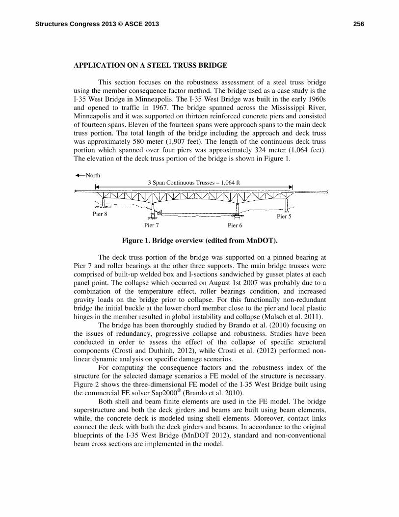
This section focuses on the robustness assessment of a steel truss bridge using the member consequence factor method. The bridge used as a case study is the I-35 West Bridge in Minneapolis. The I-35 West Bridge was built in the early 1960s and opened to traffic in 1967. The bridge spanned across the Mississippi River, Minneapolis and it was supported on thirteen reinforced concrete piers and consisted of fourteen spans. Eleven of the fourteen spans were approach spans to the main deck truss portion. The total length of the bridge including the approach and deck truss was approximately 580 meter (1,907 feet). The length of the continuous deck truss portion which spanned over four piers was approximately 324 meter (1,064 feet). The elevation of the deck truss portion of the bridge is shown in Figure 1.
Figure 1. Bridge overview (edited from MnDOT).
The deck truss portion of the bridge was supported on a pinned bearing at Pier 7 and roller bearings at the other three supports. The main bridge trusses were comprised of built-up welded box and I-sections sandwiched by gusset plates at each panel point. The collapse which occurred on August 1st 2007 was probably due to a combination of the temperature effect, roller bearings condition, and increased gravity loads on the bridge prior to collapse. For this functionally non-redundant bridge the initial buckle at the lower chord member close to the pier and local plastic hinges in the member resulted in global instability and collapse (Malsch et al. 2011).
The bridge has been thoroughly studied by Brando et al. (2010) focusing on the issues of redundancy, progressive collapse and robustness. Studies have been conducted in order to assess the effect of the collapse of specific structural components (Crosti and Duthinh, 2012), while Crosti et al. (2012) performed non-linear dynamic analysis on specific damage scenarios.
For computing the consequence factors and the robustness index of the structure for the selected damage scenarios a FE model of the structure is necessary. Figure 2 shows the three-dimensional FE model of the I-35 West Bridge built using the commercial FE solver Sap2000® (Brando et al. 2010).
Both shell and beam finite elements are used in the FE model. The bridge superstructure and both the deck girders and beams are built using beam elements, while, the concrete deck is modeled using shell elements. Moreover, contact links connect the deck with both the deck girders and beams. In accordance to the original blueprints of the I-35 West Bridge (MnDOT 2012), standard and non-conventional beam cross sections are implemented in the model.
3 Span Continuous Trusses – 1,064 ft
Pier 7 Pier 6
North
Pier 8 Pier 5
256Structures Congress 2013 © ASCE 2013
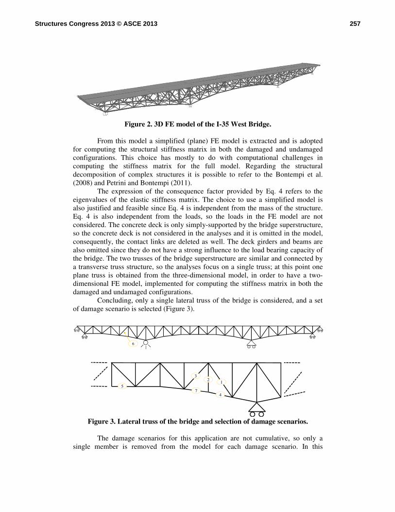
Figure 2. 3D FE model of the I-35 West Bridge.
From this model a simplified (plane) FE model is extracted and is adopted
for computing the structural stiffness matrix in both the damaged and undamaged configurations. This choice has mostly to do with computational challenges in computing the stiffness matrix for the full model. Regarding the structural decomposition of complex structures it is possible to refer to the Bontempi et al. (2008) and Petrini and Bontempi (2011).
The expression of the consequence factor provided by Eq. 4 refers to the eigenvalues of the elastic stiffness matrix. The choice to use a simplified model is also justified and feasible since Eq. 4 is independent from the mass of the structure. Eq. 4 is also independent from the loads, so the loads in the FE model are not considered. The concrete deck is only simply-supported by the bridge superstructure, so the concrete deck is not considered in the analyses and it is omitted in the model, consequently, the contact links are deleted as well. The deck girders and beams are also omitted since they do not have a strong influence to the load bearing capacity of the bridge. The two trusses of the bridge superstructure are similar and connected by a transverse truss structure, so the analyses focus on a single truss; at this point one plane truss is obtained from the three-dimensional model, in order to have a two-dimensional FE model, implemented for computing the stiffness matrix in both the damaged and undamaged configurations.
Concluding, only a single lateral truss of the bridge is considered, and a set of damage scenario is selected (Figure 3).
Figure 3. Lateral truss of the bridge and selection of damage scenarios.
The damage scenarios for this application are not cumulative, so only a
single member is removed from the model for each damage scenario. In this
6
7
2 13
4
5
257Structures Congress 2013 © ASCE 2013
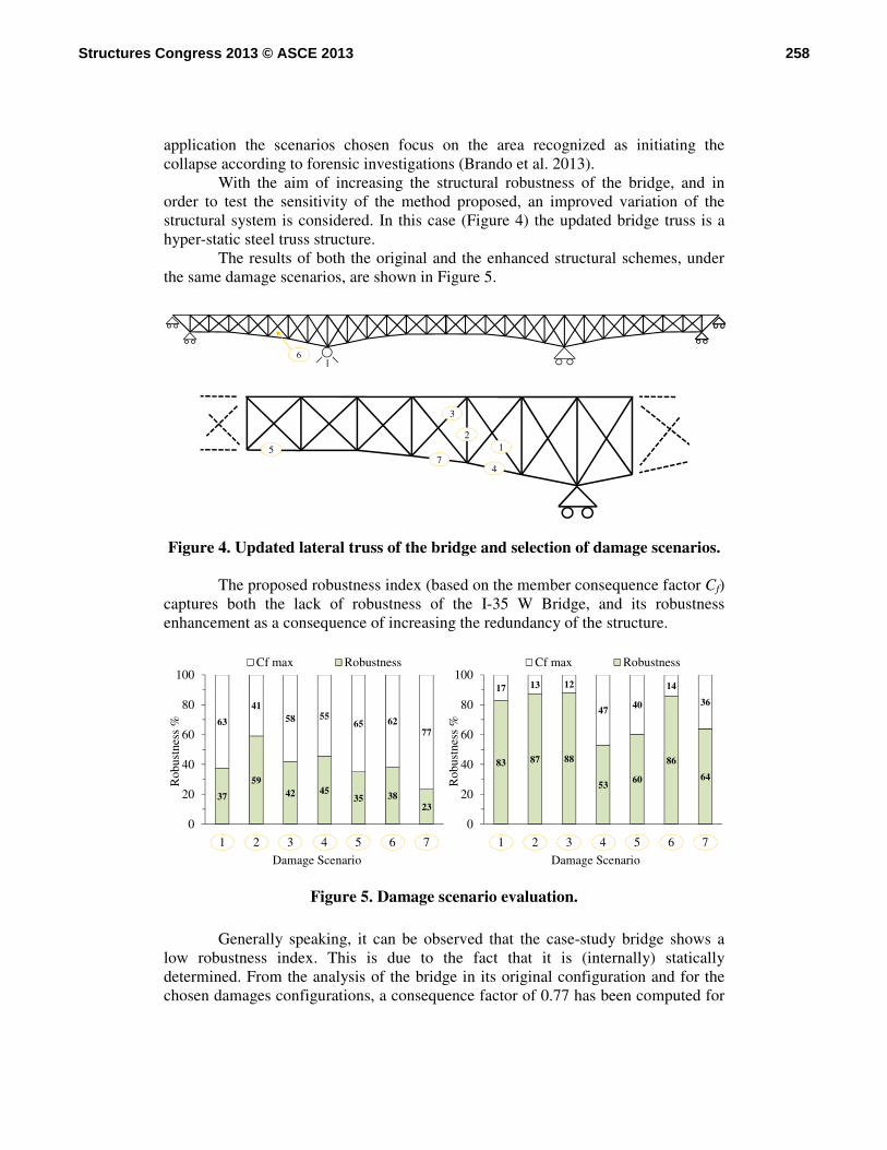
application the scenarios chosen focus on the area recognized as initiating the collapse according to forensic investigations (Brando et al. 2013).
With the aim of increasing the structural robustness of the bridge, and in order to test the sensitivity of the method proposed, an improved variation of the structural system is considered. In this case (Figure 4) the updated bridge truss is a hyper-static steel truss structure.
The results of both the original and the enhanced structural schemes, under the same damage scenarios, are shown in Figure 5.
Figure 4. Updated lateral truss of the bridge and selection of damage scenarios. The proposed robustness index (based on the member consequence factor Cf)
captures both the lack of robustness of the I-35 W Bridge, and its robustness enhancement as a consequence of increasing the redundancy of the structure.
Figure 5. Damage scenario evaluation.
Generally speaking, it can be observed that the case-study bridge shows a low robustness index. This is due to the fact that it is (internally) statically determined. From the analysis of the bridge in its original configuration and for the chosen damages configurations, a consequence factor of 0.77 has been computed for
6
7
21
3
4
5
37
5942 45
35 3823
63
4158 55
65 6277
0
20
40
60
80
100
1 2 3 4 5 6 7
Rob
ustn
ess
%
Damage Scenario
Cf max Robustness
83 87 88
53 60
86
64
17 13 12
47 40
14
36
0
20
40
60
80
100
1 2 3 4 5 6 7
Rob
ustn
ess
%
Damage Scenario
Cf max Robustness
258Structures Congress 2013 © ASCE 2013
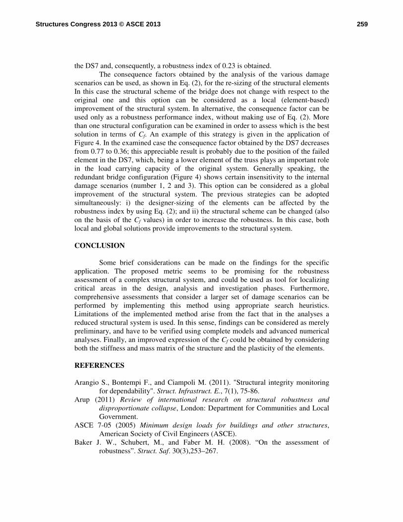
the DS7 and, consequently, a robustness index of 0.23 is obtained. The consequence factors obtained by the analysis of the various damage
scenarios can be used, as shown in Eq. (2), for the re-sizing of the structural elements In this case the structural scheme of the bridge does not change with respect to the original one and this option can be considered as a local (element-based) improvement of the structural system. In alternative, the consequence factor can be used only as a robustness performance index, without making use of Eq. (2). More than one structural configuration can be examined in order to assess which is the best solution in terms of Cf. An example of this strategy is given in the application of Figure 4. In the examined case the consequence factor obtained by the DS7 decreases from 0.77 to 0.36; this appreciable result is probably due to the position of the failed element in the DS7, which, being a lower element of the truss plays an important role in the load carrying capacity of the original system. Generally speaking, the redundant bridge configuration (Figure 4) shows certain insensitivity to the internal damage scenarios (number 1, 2 and 3). This option can be considered as a global improvement of the structural system. The previous strategies can be adopted simultaneously: i) the designer-sizing of the elements can be affected by the robustness index by using Eq. (2); and ii) the structural scheme can be changed (also on the basis of the Cf values) in order to increase the robustness. In this case, both local and global solutions provide improvements to the structural system. CONCLUSION
Some brief considerations can be made on the findings for the specific application. The proposed metric seems to be promising for the robustness assessment of a complex structural system, and could be used as tool for localizing critical areas in the design, analysis and investigation phases. Furthermore, comprehensive assessments that consider a larger set of damage scenarios can be performed by implementing this method using appropriate search heuristics. Limitations of the implemented method arise from the fact that in the analyses a reduced structural system is used. In this sense, findings can be considered as merely preliminary, and have to be verified using complete models and advanced numerical analyses. Finally, an improved expression of the Cf could be obtained by considering both the stiffness and mass matrix of the structure and the plasticity of the elements.
REFERENCES Arangio S., Bontempi F., and Ciampoli M. (2011). "Structural integrity monitoring
for dependability". Struct. Infrastruct. E., 7(1), 75-86. Arup (2011) Review of international research on structural robustness and
disproportionate collapse, London: Department for Communities and Local Government.
ASCE 7-05 (2005) Minimum design loads for buildings and other structures, American Society of Civil Engineers (ASCE).
Baker J. W., Schubert, M., and Faber M. H. (2008). “On the assessment of robustness”. Struct. Saf. 30(3),253–267.
259Structures Congress 2013 © ASCE 2013
Biondini, F., Frangopol, D. M., and Restelli, S. (2008). “On structural robustness, redundancy and static indeterminancy”. Proc. of the 2008 Structures Congress, April 24-26, 2008, Vancouver, BC, Canada.
Bontempi, F., Gkoumas, K., and Arangio, S. (2008). “Systemic approach for the maintenance of complex structural systems”. Struct. Infrastruct. E., 4(2), 77-94.
Brando, F., Testa, R.B., and Bontempi, F. (2010). “Multilevel structural analysis for robustness assessment of a steel truss bridge”. Proc. of the 5th IABMAS Conf., Philadelphia, USA, 11-15 July 2010.
Brando, F., Iannitelli, A., Cao, L., Malsch, E.A., Panariello, G., Abruzzo, J., and Pinto, M.J., (2013). “Forensic Information Modeling: a new forensic tool”, Civil Engineering magazine - American Society of Civil Engineering (ASCE), January 2013, 48-53.
Canisius, T. D. G., Sorensen, J. D., and Baker, J. W. (2007). “Robustness of structural systems - A new focus for the Joint Committee on Structural Safety (JCSS)”. Proc. of the ICASP10 Conf., Taylor and Francis, London.
Cavaco, E.S., Casas, J.R., Neves, L.A.C., and Huespe, A.E. (2013). “Robustness of corroded reinforced concrete structures - a structural performance approach”. Struct. Infrastruct. E., 9(1), 42-58.
Choi, J-h., and Chang, D-k. (2009). “Prevention of progressive collapse for building structures to member disappearance by accidental actions”. J. Loss Prevent. Proc. Ind., 22, 1016-1019.
COST (2011) TU0601 - Structural Robustness Design for Practising Engineers, Canisius, T.D.G. (Editor).
Crosti, C., and Duthinh, D. (2012). “Simplified gusset plate model for failure prediction of truss bridges”. Proc. of the 6th IABMAS Conf., Italy, Stresa, 8-12 July.
Crosti, C., Olmati, P., and Gentili, F. (2012), “Structural response of bridges to fire after explosion”. Proc. of the 6th IABMAS Conf., Italy, Stresa, 8-12 July.
DoD - Department of Defense (2009), Unified Facilities Criteria (UFC), Report No. UFC 4-023-03: Design of buildings to resist progressive collapse, Washington DC: National Institute of Building Sciences.
Ellingwood, B., and Dusenberry, D. (2005). “Building design for abnormal loads and progressive collapse”. Comput-Aided Civ. Inf., 20(3), 194-205.
EN 1991-1-7 (2006) Eurocode 1 - Actions on structures, Part 1-7: General actions – accidental actions, European Committee for Standardization (CEN).
England, J., Agarwal, J., and Blockley, D. (2008). “The vulnerability of structures to unforeseen events”. Comput. Struct., 86(10), 1042-1051.
FHWA (2011), Framework for Improving Resilience of Bridge Design, Publication No IF-11-016.
Gerasimidis, S., Bisbos, C. D., and Baniotopoulos, C.C. (2012). “Vertical geometric irregularity assessment of steel frames on robustness and disproportionate collapse”. J. Constr. Steel Res., 74, 76–89
Giuliani, L. (2012). “Structural safety in case of extreme actions”, Special Issue on: “Performance and Robustness of Complex Structural Systems”, Guest Editor Franco Bontempi, Int. J. Life Cycle Perf. Eng. (IJLCPE), 1(1), 22-40.
260Structures Congress 2013 © ASCE 2013
Izzuddin, B. A., Vlassis, A. G., Elghazouli, A. Y., and Nethercot, D. A. (2008). “Progressive collapse of multi-storey buildings due to sudden column loss - Part I: Simplified assessment framework”. Eng. Struct., 30(5), 1308-1318.
Malla, R. B., Agarwal, P., and Ahmad, R. (2011). “Dynamic analysis methodology for progressive failure of truss structures considering inelastic postbuckling cyclic member behavior”. Eng. Struct., 33(5), 1503-1513.
Malsch, E., Brando, F., Iannitelli, A., Abruzzo, J., and Panariello, G. (2011). “The Causes of the I-35 West Bridge Collapse”. Proc. 6th International Conf. on Space Structures, London.
MnDOT - Minnesota Department of Transportation (2012), Interstate 35W Bridge: Original Plans & Details.
Miyachi, K., Nakamura, S., and Manda, A. (2012). “Progressive collapse analysis of steel truss bridges and evaluation of ductility”. J. Constr. Steel Res., 78, 192-200.
Nafday, A.M. (2011). “Consequence-based structural design approach for black swan events”. Struct. Saf., 33(1), 108-114.
Nafday, A.M. (2008). “System Safety Performance Metrics for Skeletal Structures”. J. Struct. Eng.- ASCE, 134(3), 499-504.
NTSB - National Transportation Safety Board, (2007) Collapse of I-35W Highway Bridge, Minneapolis, Minnesota, August 1, 2007, NTSB/HAR-08/03.
Parisi, F., Augenti, N. (2012), “Influence of seismic design criteria on blast resistance of RC framed buildings: A case study”, Engineering Structures 44: 78-93.
Petrini F., and Bontempi F. (2011). “Estimation of fatigue life for long span suspension bridge hangers under wind action and train transit”. Struct. Infrastruct. E.,, 7(7-8), 491-507.
Petrini, F., and Ciampoli, M. (2012). “Performance-based wind design of tall buildings”. Struct. Infrastruct. E., 8(10), 954-966.
Petrini, F., Li, H., and Bontempi, F. (2010). “Basis of Design and Numerical Modeling of Offshore Wind Turbines”, Struct. Eng. Mech., 36(5), 599-624.
Saydam, D., and Frangopol, D. M. (2011). “Time-dependent performance indicators of damaged bridge superstructures”. Eng. Struct., 33(9), 2458-2471.
Sgambi, L., Gkoumas, K., and Bontempi, F. (2012). “Genetic Algorithms for the Dependability Assurance in the Design of a Long-Span Suspension Bridge”. Comput-Aided Civ. Inf., 27(9), 655-675.
Sørensen, J.D., Rizzuto, E., Narasimhan, H., and Faber, M.H. (2012). “Robustness: Theoretical framework”. Structural Engineering International: Journal of the International Association for Bridge and Structural Engineering (IABSE) 22(1), 66-72.
Starossek, U., and Haberland, M. (2010). “Disproportionate Collapse: Terminology and Procedures”. J. Perform. Constr. Facil.- ASCE, 24(6), 519-528.
Stewart, M.G., and Melchers, R.E. (1997), Probabilistic risk assessment of engineering systems, London: Chapman & Hall.
Xu, G., and Ellingwood, B. R. (2011). “An energy-based partial pushdown analysis procedure for assessment of disproportionate collapse potential”. J Constr. Steel Res., 67(3), 547-555.
261Structures Congress 2013 © ASCE 2013
Recommended