Robust Monocular Flight in Cluttered OutdoorEnvironments
Shreyansh Daftry, Sam Zeng, Arbaaz Khan, Debadeepta Dey, Narek Melik-Barkhudarov,J. Andrew Bagnell and Martial Hebert
Robotics Institute, Carnegie Mellon University, USA
Abstract—Recently, there have been numerous advances in thedevelopment of biologically inspired lightweight Micro AerialVehicles (MAVs). While autonomous navigation is fairly straight-forward for large UAVs as expensive sensors and monitoringdevices can be employed, robust methods for obstacle avoidanceremains a challenging task for MAVs which operate at lowaltitude in cluttered unstructured environments. Due to payloadand power constraints, it is necessary for such systems tohave autonomous navigation and flight capabilities using mostlypassive sensors such as cameras. In this paper, we describe arobust system that enables autonomous navigation of small agilequad-rotors at low altitude through natural forest environments.We present a direct depth estimation approach that is capableof producing accurate, semi-dense depth-maps in real time.Furthermore, a novel wind-resistant control scheme is presentedthat enables stable way-point tracking even in the presence ofstrong winds. We demonstrate the performance of our systemthrough extensive experiments on real images and field tests ina cluttered outdoor environment.
I. INTRODUCTION
Flying robots that can quickly navigate through clutteredenvironments, such as urban canyons and dense forests, havelong been an objective of robotics research [28, 37, 48, 25, 39].Even though nature is home to several species of birds thathave mastered the art of maneuverability during high-speedflights, very little have been established so far in realizingthe same for Micro Aerial Vehicles (MAVs) [22]. Inspiredby this, we take a small step in the direction of building arobust system that allows a MAV to autonomously fly at highspeeds of up to 1.5 m/s through a cluttered forest environment,as shown in Figure 1. Our work is primarily concerned withnavigating MAVs that have very low payload capabilities, andoperate close to the ground where they cannot avoid denseobstacle fields.
In recent years, MAVs have built a formidable resume bymaking themselves useful in a number of important applica-tions, from disaster scene surveillance and package delivery torobots used in aerial imaging, architecture and construction.The most important benefit of using such lightweight MAVsis that it allows the capability to fly at high speeds in space-constrained environments. However, in order to function insuch unstructured environments with complete autonomy, itis essential that they are able to avoid obstacles and navigaterobustly. While autonomous operations and obstacle avoidanceof MAVs has been well studied in general, most of theseapproaches uses laser range finders (lidar) [2, 36] or Kinect
Fig. 1. We present a novel method for high-speed, autonomous MAV flightthrough dense forest areas, using only passive monocular camera.
cameras (RGB-D sensors) [3]. For agile MAVs with verylimited payload and power, it is not feasible to carry suchactive sensors. Therefore, in this work we are interestedin methods for range mapping and obstacle avoidance foragile MAVs through unstructured environments that only haveaccess to a passive monocular camera as its primary sensingmodality.
Existing approaches for monocular cluttered flight rangefrom purely reactive approaches [33] that uses an imita-tion learning based framework for motion prediction to fullplanning-based approaches [12, 4], that utilize receding hori-zon control to plan trajectories. While promising results havebeen shown, several challenges remain that impede trulyautonomous flights in general outdoor environments withoutreliance on unrealistic assumptions. The reactive layer iscapable of good obstacle avoidance, however is inherentlymyopic in nature. This can lead to it being easily stuck in cul-de-sacs. In contrast, receding horizon based approaches planfor longer horizons and hence minimize the chances of gettingstuck [24]. These approaches require a perception method foraccurately constructing the local 3D map of the environment inreal-time. However, current perception methods for monoculardepth estimation either lack the robustness and flexibility todeal with unconstrained environments or are computationallyexpensive for real-time robotics applications.
Furthermore, the intuitive difficulties in stability and controlof such agile MAVs in the presence of strong winds is often
arX
iv:1
604.
0477
9v1
[cs
.RO
] 1
6 A
pr 2
016
overlooked. An impressive body of research on control andnavigation of MAVs has been published recently, includingaggressive maneuvers [30], which in principle should be idealto fly through forests. However, these control schemes havebeen designed to work under several strong assumptions andcontrolled laboratory conditions, which are easily alleviatedduring outdoor cluttered flights. The effect of wind on smallMAV flight control can be quite significant, and can lead tofatal conditions when flying in close proximity to clutter orother aerial vehicles [44]. It is the above considerations thatmotivate our contribution.
Our technical contributions are three-fold: First, we presentan end-to-end system consisting of a semi-dense direct visual-odometry based depth estimation approach that is capable ofproducing accurate depth maps at 15 Hz, even while the MAVis flying forward; is able to track frames even with strong inter-frame rotations using a novel method for visual-inertial fusionon Lie-manifolds, and can robustly deal with uncertainty bymaking multiple, relevant yet diverse predictions. Secondly,we introduce a novel wind-resistant LQR control based ona learned system model for stable flights in varying windconditions. Finally, we evaluate our system through extensiveexperiments and flight tests of more than 2 km in denseforest environments, and show the efficacy of our proposedperception and control modules as compared to the state-of-the-art methods.
II. RELATED WORK
Monocular Depth Estimation: Structure from Motion(SfM) approaches [47, 20, 9] can be used to reconstruct 3Dscene geometry from a moving monocular camera. While suchSfM approaches are already reasonably fast, they producesparse maps that are not suited for collision-free navigation:typically the resulting point cloud of 3D features is highlynoisy, and more crucially, the absence of visual features inregions with low texture does not necessarily imply free space.In contrast, methods for obtaining dense depth maps [31, 46]are either still too computationally expensive for high-speedflight in a forest or implicitly assume that the camera movesslowly and with sufficient translation motion. On a high speedflight, this is difficult to guarantee, as all flying maneuversinduce a change in attitude which presumably would often leadto a loss of tracking. In recent years, learning based approaches[12, 13] that aim to predict depth directly from visual featureshave shown promising results. However, these methods arehighly susceptible to training data and hence do not generalizeto unseen data, making them unsuitable for exploration basednavigation tasks.
Wind Modeling, Detection and Correction: A signif-icant literature exists on understanding wind characteristicsfor MAV guidance and navigation. More specifically, workhas been done on large scale phenomena such as thermalsoaring [1], ridge soaring [26], and exploitation of wind gusts[5, 32, 27]. However for all of these, the environment in whichthese conditions are studied are relatively benign and free of
Fig. 2. Schematic diagram of software and hardware modules.
clutter. Thus, they are strongly reliant on assumptions suchas constant wind fields and long time-scale. The reason forsuch assumptions is that short term, turbulent wind effectsare difficult to model even with detailed Computational FluidDynamics (CFD) analysis, making it impractical from a con-trol standpoint as studied by Waslander and Wang [44]. Incontrast, our work tries to explore the use of simple estimationalgorithms to detect current wind disturbances and designa controller that reduces their impact on waypoint trackingaccuracy.
III. SYSTEM OVERVIEW
We have used a modified version of the 3DR ArduCopterwith an onboard quad-core ARM processor and a Microstrain3DM-GX3-25 IMU. Onboard, there are two monocular cam-eras: one PlayStation Eye camera facing downward for realtime pose estimation and one high-dynamic range PointGreyChameleon camera for monocular navigation. We have adistributed processing framework as shown in Figure 2, wherean image stream from the front facing camera is streamed tothe base station where the perception module produces a local3D scene map; the planning module uses these maps to find thebest trajectory to follow and transmits it back to the onboardcomputer where the control module does trajectory tracking.
IV. PERCEPTION
The perception system runs on the base station and isresponsible for providing a 3D scene structure which can beused for motion planning and control strategies. In the last fewyears, direct approaches [41, 46, 42, 17] for scene geometryreconstruction have become increasingly popular. Instead ofoperating solely on visual features, these methods directlywork on the image intensities for both mapping and tracking:The world is modeled as a dense surface while in turn newframes are tracked using whole-image alignment. In this sec-tion, we build upon recently published work [15, 8] to present
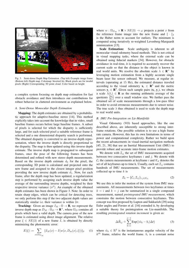
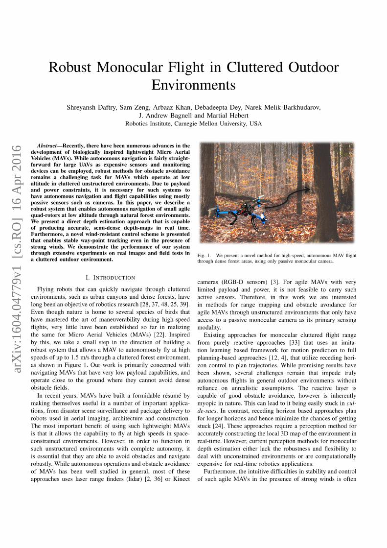
Fig. 3. Semi-dense Depth Map Estimation. (Top left) Example image frame(Bottom left) Depth map. Colormap: Inverted Jet, Black pixels are for invalidpixels (Right) Corresponding 3D point cloud. Color based on height
a complex system focusing on depth map estimation for fastobstacle avoidance and then introduces our contributions forrobust behavior in cluttered environment as explained below.
A. Semi-Dense Monocular Depth Estimation
Mapping: The depth estimates are obtained by a probabilis-tic approach for adaptive-baseline stereo [14]. This methodexplicitly takes into account the knowledge that in video, smallbaseline frames occurs before large baseline frames. A subsetof pixels is selected for which the disparity is sufficientlylarge, and for each selected pixel a suitable reference frame isselected and a one dimensional disparity search is performed.The obtained disparity is converted to an inverse-depth repre-sentation, where the inverse depth is directly proportional tothe disparity. The map is then updated using this inverse depthestimate. The inverse depth map is propagated to subsequentframes, once the pose of the following frames has beendetermined and refined with new stereo depth measurements.Based on the inverse depth estimate d0 for the pixel, thecorresponding 3D point is calculated and projected onto thenew frame and assigned to the closest integer pixel positionproviding the new inverse depth estimate d1. Now, for eachframe, after the depth map has been updated, a regularizationstep is performed by assigning each inverse depth value theaverage of the surrounding inverse depths, weighted by theirrespective inverse variance (σ2). An example of the obtaineddepth estimates has been shown in Figure 3. Note: In order toretain sharp edges, which can be critical for detecting trees,we only perform this step if the two adjacent depth values arestatistically similar i.e. their variance is within 2σ.
Tracking: Given an image IM : Ω→ R, we represent theinverse depth map as DM : ΩD → R+, where ΩD contains allpixels which have a valid depth. The camera pose of the newframe is estimated using direct image alignment. The relativepose ξ ∈ SE(3) of a new frame I , is obtained by directlyminimizing the photometric error:
E(ξ) :=∑
x∈ΩDM
‖IM (x)− I(w(x,Dm(x), ξ))‖δ (1)
where w : ΩDM× R × SE(3) → ω projects a point x from
the reference frame image into the new frame and ‖ · ‖δis the Huber norm to account for outliers. The minimum iscomputed using iteratively re-weighted Levenberg-Marquardtminimization [15].
Scale Estimation: Scale ambiguity is inherent to allmonocular visual odometry based methods. This is not criticalin visual mapping tasks, where the external scale can beobtained using fiducial markers [34]. However, for obstacleavoidance in real-time, it is required to accurately recover thecurrent scale so that the distance to the object is known inreal world units. We resolve the absolute scale λ ∈ R+ byleveraging motion estimation from a highly accurate singlebeam laser lite sensor onboard. We measure, at regular in-tervals (operating at 15 Hz), the estimated distance traveledaccording to the visual odometry xi ∈ R3 and the metricsensors yi ∈ R3. Given such sample pairs (xi, yi), we obtaina scale λ(ti) ∈ R as the running arithmetic average of thequotients ‖xi‖‖yi‖ over a small window size. We further pass theobtained set of scale measurements through a low-pass filterin order to avoid erroneous measurements due to sensor noise.The true scale λ thus obtained is used to scale the depth mapto real world units.
B. IMU Pre-Integration on Lie-Manifolds
Visual Odometry (VO) based approaches, like the onedescribed above, are inherently susceptible to strong inter-frame rotations. One possible solution is to use a high framerate camera. However, this has its own limitations in terms ofpower and computational complexity. Rather we build uponthe recent advancements in visual-inertial navigation methods[45, 21, 38] that use an Inertial Measurement Unit (IMU) toprovide robust and accurate inter-frame motion estimates.
We denote with Iij the set of IMU measurements acquiredbetween two consecutive keyframes i and j. We denote withCi the camera measurements at keyframe i and Kk denotes theset of all keyframes up to time k. Usually, each set Iij containshundreds of IMU measurements. The set of measurementscollected up to time k is
Zk = Ci, Iiji,j∈Kk(2)
We use this to infer the motion of the system from IMU mea-surements. All measurements between two keyframes at timesk = i and k = j can be summarized in a single compoundmeasurement, named preintegrated IMU measurement, whichconstrains the motion between consecutive keyframes. Thisconcept was first proposed by Lupton and Sukkarieh [29] usingEuler angles and Forster et al. [16] extended it, by developinga suitable theory for preintegration on Lie-manifolds. Theresulting preintegrated rotation increment is given as:
∆Rij.=
j−1∑
k=i
Exp((wk − bi)∆t) (3)
where wk ∈ R3 is the instantaneous angular velocity of thekth frame, relative the world frame. bi is a constant noise
bias at time ti and the shorthand ∆t.=∑jk=i ∆t. Equation 3
provides an estimate of the rotational motion between time tiand tj , as estimated from inertial measurements.
Now, the warp function w as described in Eq. 1 can bewritten as:
w(x,DM , T ) = π(Tπ−1(x,DM (x))). (4)
where π−1(x,DM ) represents the inverse projection functionand T ∈ SE(3) represents the 3D rigid body transformation.The estimated motion transform is updated using the calcu-lated preintegrated inertial rotation from the previous step suchthat
Timu =
[∆Rimu t
0 1
](5)
where ∆Rimu ∈ SO(3) and t ∈ R3. During optimization, aminimal representation for the pose is required, which is givenby the corresponding element ξ ∈ SE(3) of the associatedLie-algebra such that ξ(n)
imu = logSE(3)(Timu). In the predictionstep, the new estimate is obtained by multiplication with thecomputed update:
ξ(n+1) = δξ(n) ξ(n)imu (6)
where δ(ξ)n is computed by solving for the minimum of aGauss-Newton second order approximation of the photometricerror E. As the optimizer is fed with more robust rotationalestimates, the resulting pose after visual-inertial fusion is lesssusceptible to strong inter-frame rotations.
C. Multiple Predictions
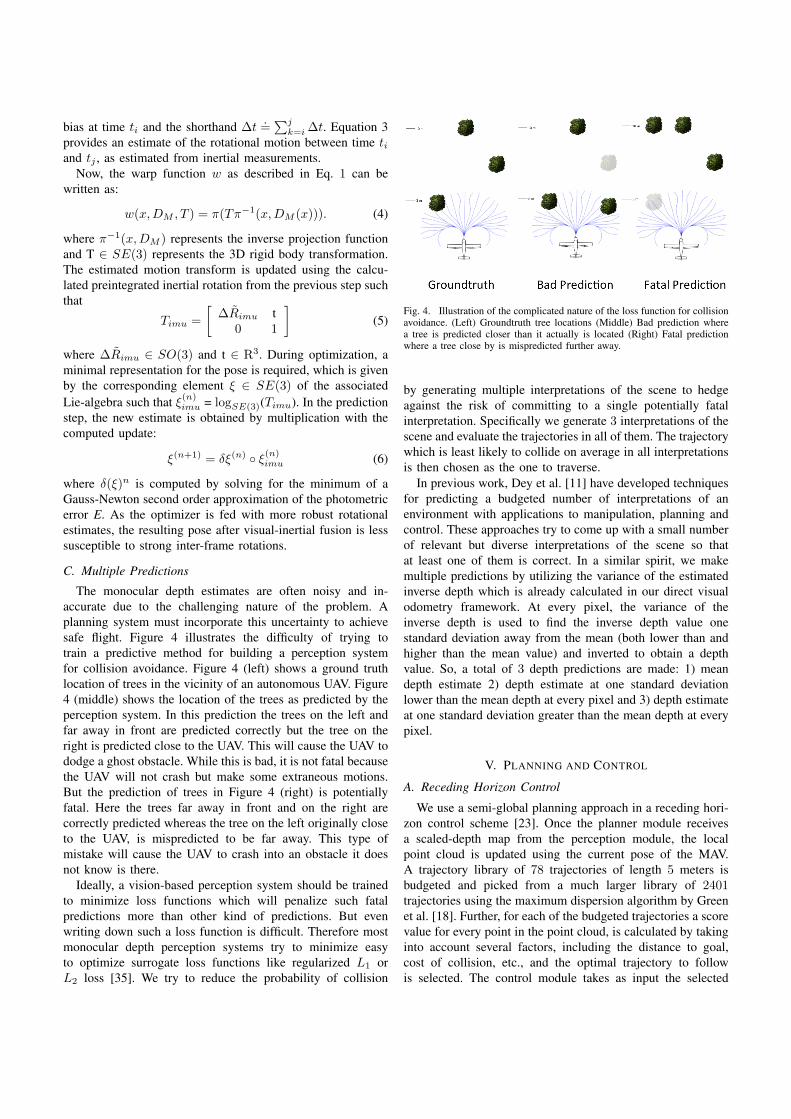
The monocular depth estimates are often noisy and in-accurate due to the challenging nature of the problem. Aplanning system must incorporate this uncertainty to achievesafe flight. Figure 4 illustrates the difficulty of trying totrain a predictive method for building a perception systemfor collision avoidance. Figure 4 (left) shows a ground truthlocation of trees in the vicinity of an autonomous UAV. Figure4 (middle) shows the location of the trees as predicted by theperception system. In this prediction the trees on the left andfar away in front are predicted correctly but the tree on theright is predicted close to the UAV. This will cause the UAV tododge a ghost obstacle. While this is bad, it is not fatal becausethe UAV will not crash but make some extraneous motions.But the prediction of trees in Figure 4 (right) is potentiallyfatal. Here the trees far away in front and on the right arecorrectly predicted whereas the tree on the left originally closeto the UAV, is mispredicted to be far away. This type ofmistake will cause the UAV to crash into an obstacle it doesnot know is there.
Ideally, a vision-based perception system should be trainedto minimize loss functions which will penalize such fatalpredictions more than other kind of predictions. But evenwriting down such a loss function is difficult. Therefore mostmonocular depth perception systems try to minimize easyto optimize surrogate loss functions like regularized L1 orL2 loss [35]. We try to reduce the probability of collision
Fig. 4. Illustration of the complicated nature of the loss function for collisionavoidance. (Left) Groundtruth tree locations (Middle) Bad prediction wherea tree is predicted closer than it actually is located (Right) Fatal predictionwhere a tree close by is mispredicted further away.
by generating multiple interpretations of the scene to hedgeagainst the risk of committing to a single potentially fatalinterpretation. Specifically we generate 3 interpretations of thescene and evaluate the trajectories in all of them. The trajectorywhich is least likely to collide on average in all interpretationsis then chosen as the one to traverse.
In previous work, Dey et al. [11] have developed techniquesfor predicting a budgeted number of interpretations of anenvironment with applications to manipulation, planning andcontrol. These approaches try to come up with a small numberof relevant but diverse interpretations of the scene so thatat least one of them is correct. In a similar spirit, we makemultiple predictions by utilizing the variance of the estimatedinverse depth which is already calculated in our direct visualodometry framework. At every pixel, the variance of theinverse depth is used to find the inverse depth value onestandard deviation away from the mean (both lower than andhigher than the mean value) and inverted to obtain a depthvalue. So, a total of 3 depth predictions are made: 1) meandepth estimate 2) depth estimate at one standard deviationlower than the mean depth at every pixel and 3) depth estimateat one standard deviation greater than the mean depth at everypixel.
V. PLANNING AND CONTROL
A. Receding Horizon Control
We use a semi-global planning approach in a receding hori-zon control scheme [23]. Once the planner module receivesa scaled-depth map from the perception module, the localpoint cloud is updated using the current pose of the MAV.A trajectory library of 78 trajectories of length 5 meters isbudgeted and picked from a much larger library of 2401trajectories using the maximum dispersion algorithm by Greenet al. [18]. Further, for each of the budgeted trajectories a scorevalue for every point in the point cloud, is calculated by takinginto account several factors, including the distance to goal,cost of collision, etc., and the optimal trajectory to followis selected. The control module takes as input the selected
trajectory to follow and generates waypoints to track usinga pure pursuit strategy [6]. Using the pose estimates of thevehicle, the MAV moves towards the next waypoint using aLQR controller as described in Section V-C. For further detailson our planning approach, we direct the reader to previouswork by Dey et al. [12].
B. State Estimation
In receding horizon, one only needs a relative, consistentpose estimation system as trajectories are followed only for ashort duration. As looking forward to determine pose is ill-conditioned due to a lack of parallax, we use a downwardlooking camera in conjunction with a sonar for determiningthis relative pose. We used a variant of a simple algorithmthat has been presented quite often, most recently in [19].This approach uses a Kanade-Lucas-Tomasi (KLT) tracker[43] to detect where each pixel in a grid of pixels movesover consecutive frames, and estimating the mean flow fromthese after rejecting outliers. Additionaly, out-of-plane cameraego-motion is compensated using motion information fromthe IMU and the metric scale is estimated from sonar. Thecomputed instantaneous relative velocity between the cameraand ground is integrated over time to get position.
C. Wind-Resistant LQR Control
In this section, we describe our proposed approach for wind-resistant LQR control. The problem under consideration canbe described as follows: Given the knowledge of the currentand past states of the MAV, can we estimate the currentwind conditions and determine appropriate control actionsthat would help recover from these expected disturbances? Tothis end, we propose to learn a dynamic model of our MAVand observe the errors in the model’s predictions in windyconditions, and compare them to errors in calm conditions inorder to determine the magnitude and direction of the wind.These observations can be built into a learned model for windbehavior, which allows for future control commands to beadjusted for the predicted effects of the wind.
System Identification: Given the application and therequisite desired performance, we are only interested in the ve-hicle dynamics involving small angular deviations and angularvelocities. Thus, we linearize the dynamics and approximatethe MAV as a linear system. Now, while this is trivial for rolland pitch, yaw is not limited to small angles in our motionmodel, resulting in a non-linear behavior. This non-linearitycan be removed by building our model in the world frame andtransforming the results to the robot frame when necessary.Thus, the robot’s motion model can be represented by thefollowing state space equation:
x(t+ 1) = Ax(t) + Bu(t) (7)
where the state vector x = [x, y, x, y, θ] consists of x and y po-sitions, x and y velocities and the yaw angle and u = [η, φ, θ]is the control input vector consisting of roll, pitch and yawcontrol commands. The matrices A and B can be obtainedanalytically by system parameters such as mass, moment
of inertia, center of mass, etc. However. these parametersare difficult to obtain in practice. Moreover, this approachcannot model the effects of the time varying aerodynamicforces. Alternatively, we run a large number of experimentsto record the state and command data from actual flight andthen learn the matrices A and B that best fit the data. In thiswork, we recast the system identification problem into a leastsquare solution to an overdetermined set of linear equations.Specifically, the state space equations can be condensed intothe form
X(t+ 1) = [A,B]
[x(t)u(t)
](8)
where the matrix [A,B] can be solved using linear regression.Wind Modeling, Detection, and Resistance: Traditional
approaches for wind detection, model the gust forces assuminga static dominant direction derived from the Drysden model[40]. However, this model is only applicable to MAVs in openterrain and fails for MAV flights in cluttered environments likeforests, as the gush of wind has a profile of varying velocityon a time-scale shorter than the scale of the vehicle flight time.Thus, we use an alternate approach for determining the winddisturbance, which relies on the use of the acceleration data. Inour proposed approach we attempt to understand the behaviorsof our learned system model in both windy and wind-freeconditions. Any deviations that should occur, given the currentstate and inputs, can be attributed to wind disturbances. Inparticular, the effects of the wind on the system dynamicscan be observed by analyzing the differences in model errorsin both conditions (See Figure 8a). The magnitude of thedifference at a given time represents the current wind impacton the MAV and the direction can be determined by x and ycomponents of the velocity error since the wind should causeunexpected acceleration in the direction of the wind.
Furthermore, the differences in model errors between theaverage error distribution and the current real time distributionat a given time can be broken down into each state’s error.Additionally, if we assume that the current wind magnitudeand direction is the same as it was in the previous time step, theMAV model’s state can be extended to include wind resultingin a new model:
x(t+ 1) = Ax(t) + Bu(t) + w(t) (9)
where w = [wx, wy, wx, wy, 0] are the wind-bias correctionterms corresponding to x, y positions and x, y velocities. Weassume the wind to have no impact on the yaw angles. Thevalidity of these assumptions can be determined by observingthe variance in the previous N errors. If the variance is low, itis likely that the next error will be the same as the past few andso the model should be updated to correct for this error sincewind comes in low frequency bursts. If the variance is high,then the error is can be attributed to random noise or othermodeling error and it is ignored in future predictions. Thisprocess can be executed in real time during flight allowing forcurrent estimates for the wind force.
LQR Controller Design: The system dynamics model isused to implement an output feedback control law to track
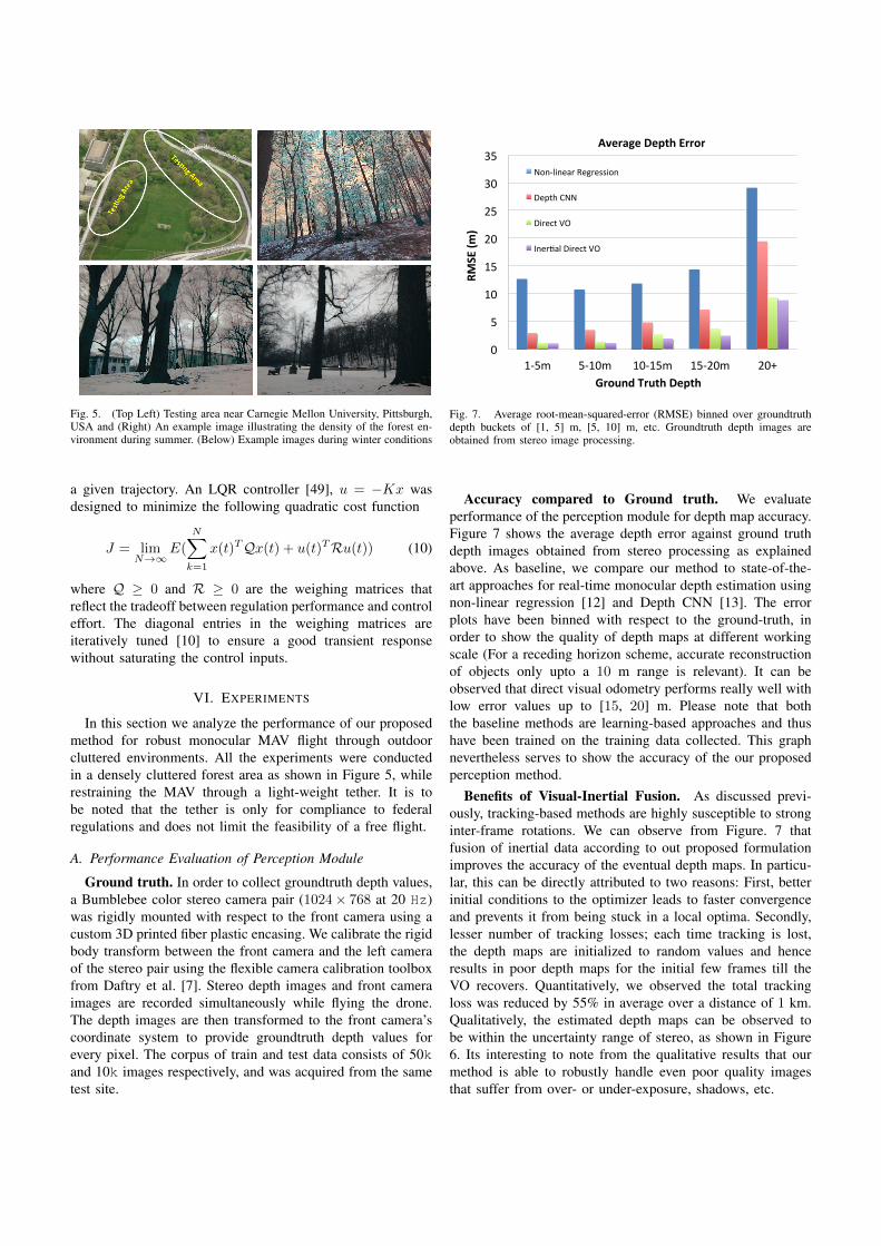
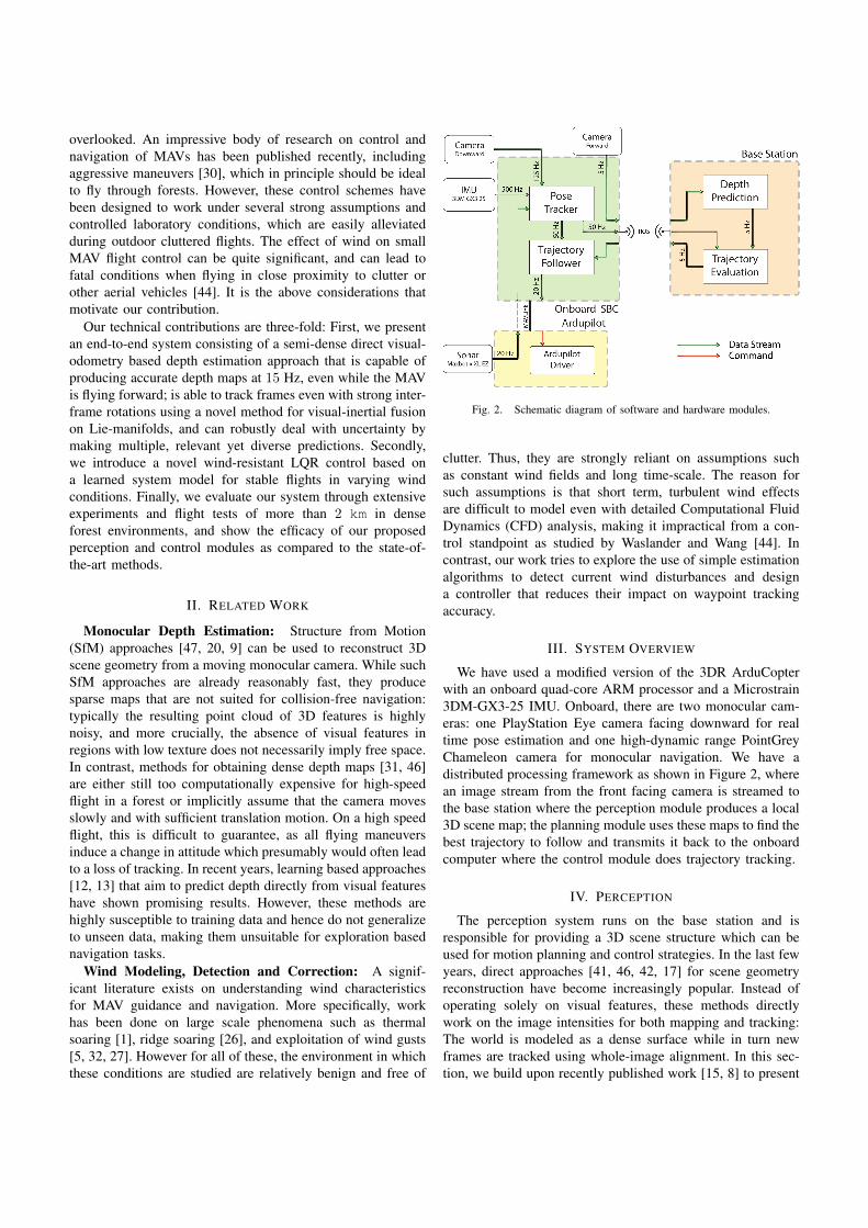
Fig. 5. (Top Left) Testing area near Carnegie Mellon University, Pittsburgh,USA and (Right) An example image illustrating the density of the forest en-vironment during summer. (Below) Example images during winter conditions
a given trajectory. An LQR controller [49], u = −Kx wasdesigned to minimize the following quadratic cost function
J = limN→∞
E(N∑
k=1
x(t)TQx(t) + u(t)TRu(t)) (10)
where Q ≥ 0 and R ≥ 0 are the weighing matrices thatreflect the tradeoff between regulation performance and controleffort. The diagonal entries in the weighing matrices areiteratively tuned [10] to ensure a good transient responsewithout saturating the control inputs.
VI. EXPERIMENTS
In this section we analyze the performance of our proposedmethod for robust monocular MAV flight through outdoorcluttered environments. All the experiments were conductedin a densely cluttered forest area as shown in Figure 5, whilerestraining the MAV through a light-weight tether. It is tobe noted that the tether is only for compliance to federalregulations and does not limit the feasibility of a free flight.
A. Performance Evaluation of Perception Module
Ground truth. In order to collect groundtruth depth values,a Bumblebee color stereo camera pair (1024× 768 at 20 Hz)was rigidly mounted with respect to the front camera using acustom 3D printed fiber plastic encasing. We calibrate the rigidbody transform between the front camera and the left cameraof the stereo pair using the flexible camera calibration toolboxfrom Daftry et al. [7]. Stereo depth images and front cameraimages are recorded simultaneously while flying the drone.The depth images are then transformed to the front camera’scoordinate system to provide groundtruth depth values forevery pixel. The corpus of train and test data consists of 50kand 10k images respectively, and was acquired from the sametest site.
0
5
10
15
20
25
30
35
1-‐5m 5-‐10m 10-‐15m 15-‐20m 20+
RMSE (m
)
Ground Truth Depth
Average Depth Error
Non-‐linear Regression
Depth CNN
Direct VO
Iner>al Direct VO
Fig. 7. Average root-mean-squared-error (RMSE) binned over groundtruthdepth buckets of [1, 5] m, [5, 10] m, etc. Groundtruth depth images areobtained from stereo image processing.
Accuracy compared to Ground truth. We evaluateperformance of the perception module for depth map accuracy.Figure 7 shows the average depth error against ground truthdepth images obtained from stereo processing as explainedabove. As baseline, we compare our method to state-of-the-art approaches for real-time monocular depth estimation usingnon-linear regression [12] and Depth CNN [13]. The errorplots have been binned with respect to the ground-truth, inorder to show the quality of depth maps at different workingscale (For a receding horizon scheme, accurate reconstructionof objects only upto a 10 m range is relevant). It can beobserved that direct visual odometry performs really well withlow error values up to [15, 20] m. Please note that boththe baseline methods are learning-based approaches and thushave been trained on the training data collected. This graphnevertheless serves to show the accuracy of the our proposedperception method.
Benefits of Visual-Inertial Fusion. As discussed previ-ously, tracking-based methods are highly susceptible to stronginter-frame rotations. We can observe from Figure. 7 thatfusion of inertial data according to out proposed formulationimproves the accuracy of the eventual depth maps. In particu-lar, this can be directly attributed to two reasons: First, betterinitial conditions to the optimizer leads to faster convergenceand prevents it from being stuck in a local optima. Secondly,lesser number of tracking losses; each time tracking is lost,the depth maps are initialized to random values and henceresults in poor depth maps for the initial few frames till theVO recovers. Quantitatively, we observed the total trackingloss was reduced by 55% in average over a distance of 1 km.Qualitatively, the estimated depth maps can be observed tobe within the uncertainty range of stereo, as shown in Figure6. Its interesting to note from the qualitative results that ourmethod is able to robustly handle even poor quality imagesthat suffer from over- or under-exposure, shadows, etc.
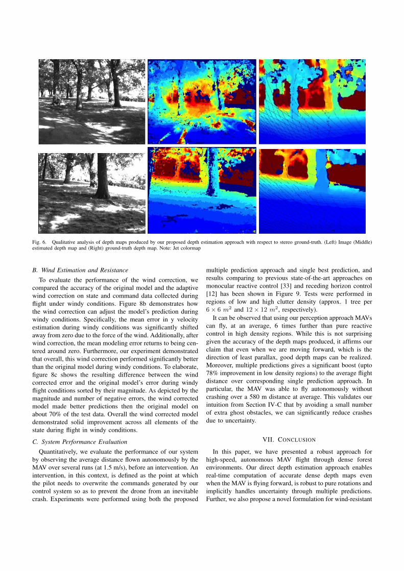
Fig. 6. Qualitative analysis of depth maps produced by our proposed depth estimation approach with respect to stereo ground-truth. (Left) Image (Middle)estimated depth map and (Right) ground-truth depth map. Note: Jet colormap
B. Wind Estimation and Resistance
To evaluate the performance of the wind correction, wecompared the accuracy of the original model and the adaptivewind correction on state and command data collected duringflight under windy conditions. Figure 8b demonstrates howthe wind correction can adjust the model’s prediction duringwindy conditions. Specifically, the mean error in y velocityestimation during windy conditions was significantly shiftedaway from zero due to the force of the wind. Additionally, afterwind correction, the mean modeling error returns to being cen-tered around zero. Furthermore, our experiment demonstratedthat overall, this wind correction performed significantly betterthan the original model during windy conditions. To elaborate,figure 8c shows the resulting difference between the windcorrected error and the original model’s error during windyflight conditions sorted by their magnitude. As depicted by themagnitude and number of negative errors, the wind correctedmodel made better predictions then the original model onabout 70% of the test data. Overall the wind corrected modeldemonstrated solid improvement across all elements of thestate during flight in windy conditions.
C. System Performance Evaluation
Quantitatively, we evaluate the performance of our systemby observing the average distance flown autonomously by theMAV over several runs (at 1.5 m/s), before an intervention. Anintervention, in this context, is defined as the point at whichthe pilot needs to overwrite the commands generated by ourcontrol system so as to prevent the drone from an inevitablecrash. Experiments were performed using both the proposed
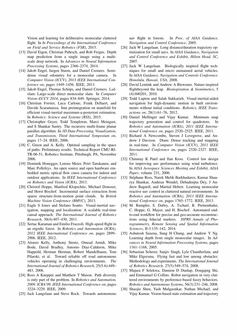
multiple prediction approach and single best prediction, andresults comparing to previous state-of-the-art approaches onmonocular reactive control [33] and receding horizon control[12] has been shown in Figure 9. Tests were performed inregions of low and high clutter density (approx. 1 tree per6× 6 m2 and 12× 12 m2, respectively).
It can be observed that using our perception approach MAVscan fly, at an average, 6 times further than pure reactivecontrol in high density regions. While this is not surprisinggiven the accuracy of the depth maps produced, it affirms ourclaim that even when we are moving forward, which is thedirection of least parallax, good depth maps can be realized.Moreover, multiple predictions gives a significant boost (upto78% improvement in low density regions) to the average flightdistance over corresponding single prediction approach. Inparticular, the MAV was able to fly autonomously withoutcrashing over a 580 m distance at average. This validates ourintuition from Section IV-C that by avoiding a small numberof extra ghost obstacles, we can significantly reduce crashesdue to uncertainty.
VII. CONCLUSION
In this paper, we have presented a robust approach forhigh-speed, autonomous MAV flight through dense forestenvironments. Our direct depth estimation approach enablesreal-time computation of accurate dense depth maps evenwhen the MAV is flying forward, is robust to pure rotations andimplicitly handles uncertainty through multiple predictions.Further, we also propose a novel formulation for wind-resistant
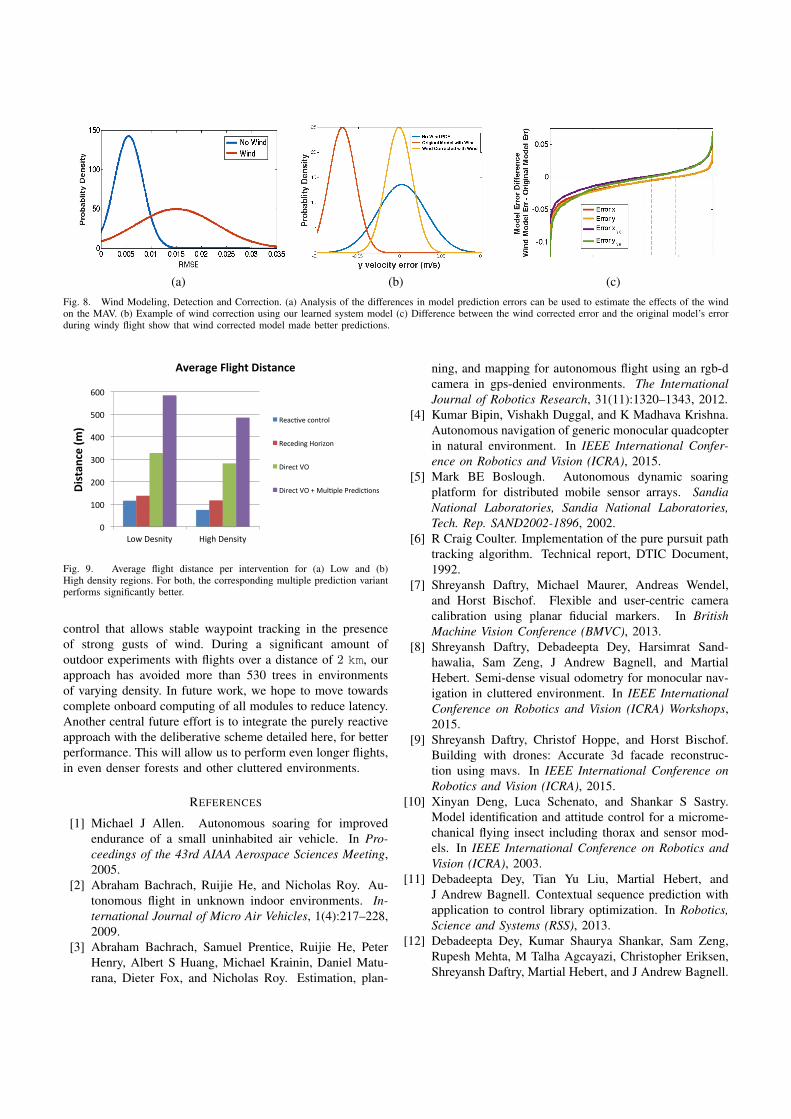
(a) (b) (c)Fig. 8. Wind Modeling, Detection and Correction. (a) Analysis of the differences in model prediction errors can be used to estimate the effects of the windon the MAV. (b) Example of wind correction using our learned system model (c) Difference between the wind corrected error and the original model’s errorduring windy flight show that wind corrected model made better predictions.
0
100
200
300
400
500
600
Low Desnity High Density
Distan
ce (m
)
Average Flight Distance
Reac9ve control
Receding Horizon
Direct VO
Direct VO + Mul9ple Predic9ons
Fig. 9. Average flight distance per intervention for (a) Low and (b)High density regions. For both, the corresponding multiple prediction variantperforms significantly better.
control that allows stable waypoint tracking in the presenceof strong gusts of wind. During a significant amount ofoutdoor experiments with flights over a distance of 2 km, ourapproach has avoided more than 530 trees in environmentsof varying density. In future work, we hope to move towardscomplete onboard computing of all modules to reduce latency.Another central future effort is to integrate the purely reactiveapproach with the deliberative scheme detailed here, for betterperformance. This will allow us to perform even longer flights,in even denser forests and other cluttered environments.
REFERENCES
[1] Michael J Allen. Autonomous soaring for improvedendurance of a small uninhabited air vehicle. In Pro-ceedings of the 43rd AIAA Aerospace Sciences Meeting,2005.
[2] Abraham Bachrach, Ruijie He, and Nicholas Roy. Au-tonomous flight in unknown indoor environments. In-ternational Journal of Micro Air Vehicles, 1(4):217–228,2009.
[3] Abraham Bachrach, Samuel Prentice, Ruijie He, PeterHenry, Albert S Huang, Michael Krainin, Daniel Matu-rana, Dieter Fox, and Nicholas Roy. Estimation, plan-
ning, and mapping for autonomous flight using an rgb-dcamera in gps-denied environments. The InternationalJournal of Robotics Research, 31(11):1320–1343, 2012.
[4] Kumar Bipin, Vishakh Duggal, and K Madhava Krishna.Autonomous navigation of generic monocular quadcopterin natural environment. In IEEE International Confer-ence on Robotics and Vision (ICRA), 2015.
[5] Mark BE Boslough. Autonomous dynamic soaringplatform for distributed mobile sensor arrays. SandiaNational Laboratories, Sandia National Laboratories,Tech. Rep. SAND2002-1896, 2002.
[6] R Craig Coulter. Implementation of the pure pursuit pathtracking algorithm. Technical report, DTIC Document,1992.
[7] Shreyansh Daftry, Michael Maurer, Andreas Wendel,and Horst Bischof. Flexible and user-centric cameracalibration using planar fiducial markers. In BritishMachine Vision Conference (BMVC), 2013.
[8] Shreyansh Daftry, Debadeepta Dey, Harsimrat Sand-hawalia, Sam Zeng, J Andrew Bagnell, and MartialHebert. Semi-dense visual odometry for monocular nav-igation in cluttered environment. In IEEE InternationalConference on Robotics and Vision (ICRA) Workshops,2015.
[9] Shreyansh Daftry, Christof Hoppe, and Horst Bischof.Building with drones: Accurate 3d facade reconstruc-tion using mavs. In IEEE International Conference onRobotics and Vision (ICRA), 2015.
[10] Xinyan Deng, Luca Schenato, and Shankar S Sastry.Model identification and attitude control for a microme-chanical flying insect including thorax and sensor mod-els. In IEEE International Conference on Robotics andVision (ICRA), 2003.
[11] Debadeepta Dey, Tian Yu Liu, Martial Hebert, andJ Andrew Bagnell. Contextual sequence prediction withapplication to control library optimization. In Robotics,Science and Systems (RSS), 2013.
[12] Debadeepta Dey, Kumar Shaurya Shankar, Sam Zeng,Rupesh Mehta, M Talha Agcayazi, Christopher Eriksen,Shreyansh Daftry, Martial Hebert, and J Andrew Bagnell.
Vision and learning for deliberative monocular clutteredflight. In In Proceedings of the International Conferenceon Field and Service Robotics (FSR), 2015.
[13] David Eigen, Christian Puhrsch, and Rob Fergus. Depthmap prediction from a single image using a multi-scale deep network. In Advances in Neural InformationProcessing Systems, pages 2366–2374, 2014.
[14] Jakob Engel, Jurgen Sturm, and Daniel Cremers. Semi-dense visual odometry for a monocular camera. InComputer Vision (ICCV), 2013 IEEE International Con-ference on, pages 1449–1456. IEEE, 2013.
[15] Jakob Engel, Thomas Schops, and Daniel Cremers. Lsd-slam: Large-scale direct monocular slam. In ComputerVision–ECCV 2014, pages 834–849. Springer, 2014.
[16] Christian Forster, Luca Carlone, Frank Dellaert, andDavide Scaramuzza. Imu preintegration on manifold forefficient visual-inertial maximum-a-posteriori estimation.In Robotics: Science and Systems (RSS), 2015.
[17] Christopher Geyer, Todd Templeton, Marci Meingast,and S Shankar Sastry. The recursive multi-frame planarparallax algorithm. In 3D Data Processing, Visualization,and Transmission, Third International Symposium on,pages 17–24. IEEE, 2006.
[18] C. Green and A. Kelly. Optimal sampling in the spaceof paths: Preliminary results. Technical Report CMU-RI-TR-06-51, Robotics Institute, Pittsburgh, PA, November2006.
[19] Dominik Honegger, Lorenz Meier, Petri Tanskanen, andMarc Pollefeys. An open source and open hardware em-bedded metric optical flow cmos camera for indoor andoutdoor applications. In IEEE International Conferenceon Robotics and Vision (ICRA), 2013.
[20] Christof Hoppe, Manfred Klopschitz, Michael Donoser,and Horst Bischof. Incremental surface extraction fromsparse structure-from-motion point clouds. In BritishMachine Vision Conference (BMVC), 2013.
[21] Eagle S Jones and Stefano Soatto. Visual-inertial nav-igation, mapping and localization: A scalable real-timecausal approach. The International Journal of RoboticsResearch, 30(4):407–430, 2011.
[22] Sertac Karaman and Emilio Frazzoli. High-speed flight inan ergodic forest. In Robotics and Automation (ICRA),2012 IEEE International Conference on, pages 2899–2906. IEEE, 2012.
[23] Alonzo Kelly, Anthony Stentz, Omead Amidi, MikeBode, David Bradley, Antonio Diaz-Calderon, MikeHappold, Herman Herman, Robert Mandelbaum, TomPilarski, et al. Toward reliable off road autonomousvehicles operating in challenging environments. TheInternational Journal of Robotics Research, 25(5-6):449–483, 2006.
[24] Ross A Knepper and Matthew T Mason. Path diversityis only part of the problem. In Robotics and Automation,2009. ICRA’09. IEEE International Conference on, pages3224–3229. IEEE, 2009.
[25] Jack Langelaan and Steve Rock. Towards autonomous
uav flight in forests. In Proc. of AIAA Guidance,Navigation and Control Conference, 2005.
[26] Jack W Langelaan. Long distance/duration trajectory op-timization for small uavs. In AIAA Guidance, Navigationand Control Conference and Exhibit, Hilton Head, SC,2007.
[27] Jack W Langelaan. Biologically inspired flight tech-niques for small and micro unmanned aerial vehicles.In AIAA Guidance, Navigation and Controls Conference.Honolulu, Hawaii, USA, 2008.
[28] David Lentink and Andrew A Biewener. Nature-inspiredflightbeyond the leap. Bioinspiration & biomimetics, 5(4):040201, 2010.
[29] Todd Lupton and Salah Sukkarieh. Visual-inertial-aidednavigation for high-dynamic motion in built environ-ments without initial conditions. Robotics, IEEE Trans-actions on, 28(1):61–76, 2012.
[30] Daniel Mellinger and Vijay Kumar. Minimum snaptrajectory generation and control for quadrotors. InRobotics and Automation (ICRA), 2011 IEEE Interna-tional Conference on, pages 2520–2525. IEEE, 2011.
[31] Richard A Newcombe, Steven J Lovegrove, and An-drew J Davison. Dtam: Dense tracking and mappingin real-time. In Computer Vision (ICCV), 2011 IEEEInternational Conference on, pages 2320–2327. IEEE,2011.
[32] Chinmay K Patel and Ilan Kroo. Control law designfor improving uav performance using wind turbulence.In AIAA Aerospace Sciences Meeting and Exhibit, AIAAPaper, volume 231, 2006.
[33] Stephane Ross, Narek Melik-Barkhudarov, Kumar Shau-rya Shankar, Andreas Wendel, Debadeepta Dey, J An-drew Bagnell, and Martial Hebert. Learning monocularreactive uav control in cluttered natural environments. InRobotics and Automation (ICRA), 2013 IEEE Interna-tional Conference on, pages 1765–1772. IEEE, 2013.
[34] M. Rumpler, S. Daftry, A. Tscharf, R. Prettenthaler,C. Hoppe, G. Mayer, and H. Bischof. Automated end-to-end workflow for precise and geo-accurate reconstruc-tions using fiducial markers. ISPRS Annals of Pho-togrammetry, Remote Sensing and Spatial InformationSciences, II-3:135–142, 2014.
[35] Ashutosh Saxena, Sung H Chung, and Andrew Y Ng.Learning depth from single monocular images. In Ad-vances in Neural Information Processing Systems, pages1161–1168, 2005.
[36] Sebastian Scherer, Sanjiv Singh, Lyle Chamberlain, andMike Elgersma. Flying fast and low among obstacles:Methodology and experiments. The International Journalof Robotics Research, 27(5):549–574, 2008.
[37] Majura F Selekwa, Damion D Dunlap, Dongqing Shi,and Emmanuel G Collins. Robot navigation in very clut-tered environments by preference-based fuzzy behaviors.Robotics and Autonomous Systems, 56(3):231–246, 2008.
[38] Shaojie Shen, Yash Mulgaonkar, Nathan Michael, andVijay Kumar. Vision-based state estimation and trajectory
control towards high-speed flight with a quadrotor. InRobotics: Science and Systems. Citeseer, 2013.
[39] David Shim, Hoam Chung, H Jin Kim, and ShankarSastry. Autonomous exploration in unknown urbanenvironments for unmanned aerial vehicles. In Proc.AIAA GN&C Conference, 2005.
[40] Military Specification. Flying qualities of piloted air-planes. United States Department of Defense, 1980.
[41] Jan Stuhmer, Stefan Gumhold, and Daniel Cremers.Real-time dense geometry from a handheld camera. InPattern Recognition, pages 11–20. Springer, 2010.
[42] Todd Templeton. Accurate real-time reconstruction ofdistant scenes using computer vision: The recursivemulti-frame planar parallax algorithm. 2009.
[43] Carlo Tomasi and Takeo Kanade. Detection and trackingof point features. School of Computer Science, CarnegieMellon Univ., 1991.
[44] Steven L Waslander and Carlos Wang. Wind disturbanceestimation and rejection for quadrotor position control.In AIAA Infotech@ Aerospace Conference and AIAAUnmanned... Unlimited Conference, Seattle, WA, 2009.
[45] Stephan Weiss, Markus W Achtelik, Simon Lynen, Mar-garita Chli, and Roland Siegwart. Real-time onboardvisual-inertial state estimation and self-calibration ofmavs in unknown environments. In Robotics and Au-tomation (ICRA), 2012 IEEE International Conferenceon, pages 957–964. IEEE, 2012.
[46] Andreas Wendel, Michael Maurer, Gottfried Graber,Thomas Pock, and Horst Bischof. Dense reconstructionon-the-fly. In Computer Vision and Pattern Recognition(CVPR), 2012 IEEE Conference on, pages 1450–1457.IEEE, 2012.
[47] Changchang Wu. Towards linear-time incremental struc-ture from motion. In 3D Vision-3DV 2013, 2013 Inter-national Conference on, pages 127–134. IEEE, 2013.
[48] Kwangjin Yang and Salah Sukkarieh. 3d smooth pathplanning for a uav in cluttered natural environments.In Intelligent Robots and Systems, 2008. IROS 2008.IEEE/RSJ International Conference on, pages 794–800.IEEE, 2008.
[49] Kemin Zhou, John Comstock Doyle, Keith Glover, et al.Robust and optimal control, volume 40. Prentice hallNew Jersey, 1996.
Recommended