Road & Bridge Design Publications
Monthly Update – April 2012
1
Revisions for the month of April are listed and displayed below. New special details are to be included in projects submitted for the July letting as is stated on the special detail index sheets. Please contact Wayne Pikka ([email protected]) for any questions related to the road changes or Vladimir Zokvic ([email protected]) for questions related to the bridge changes. Special Details R-41-G: Longitudinal Pavement Joints: A note was added to the note sheet which specifies a bond release agent for the epoxy coated symbol “S” tie bars. R-80-E: Granular Blankets, Under Drains & Outlet Endings, & Sewer Bulkheads: A few minor modifications were made to clarify the changes from last month. (Class II AA material is only used in bank drains when directly above an unlined under drain and lines were drawn above the under drains on sheet 3 to separate the subbase from the Class II AA material.) Road Design Manual 3.11.03: Freeway 3R/4R Design Speed: This section was deleted. Design speed is fully covered in section 3.06. 7.01.11C: Clear Zone: The 65-70 mph design speed in the clear zone chart was revised to > 65 mph. 7.01.11D: Curve Correction Factor Table: In the table, degree of curve was revised to radius and the factors adjusted. Bridge Design Manual 7.02.19 C. & 7.02.20 G. (LRFD & LFD): Added criteria for reinforcement of haunches greater than 6 inches. Bridge Design Guides 6.42.03 A: New guide detailing reinforcement of haunches greater than 6 inches.

Road & Bridge Design Publications
Monthly Update – April 2012
2
Please note: Corresponding updates to automated tools, including but not limited to the MDOT Bulletin Board, MDOT Cell Library, Bridge Auto Draw Program, etc., may be required in tandem with some of this month's updates. Until such updates to automated tools can be made, it is the designer's/detailer's responsibility to manually incorporate any necessary revisions to notes and plan details to reflect these revisions.

Index to Special Details
4-23-2012
SPECIAL DETAIL
NUMBER
NUMBER
OF SHEETS
TITLE
CURRENT
DATE
21
2 GUARDRAIL AT INTERSECTIONS
5-24-01
24
5
GUARDRAIL ANCHORED IN BACK SLOPE TYPES 4B & 4T
7-22-02
R-29-H
4
DRIVEWAY OPENINGS & APPROACHES, AND CONCRETE SIDEWALK
10-20-11
R-31-F
2
INTEGRAL CURB AND INTEGRAL CURB & GUTTER
1-30-12
* R-41-G
2
LONGITUDINAL PAVEMENT JOINTS
4-9-12
R-42-F
6
TYPICAL JOINT LAYOUTS FOR CONCRETE PAVEMENT
12-6-10
R-43-I
2
LOCATION OF TRANSVERSE JOINTS IN PLAIN CONCRETE PAVEMENT
2-8-12
R-45-I
2 PAVEMENT REINFORCEMENT FOR BRIDGE APPROACH
12-6-11
* R-80-E
8
GRANULAR BLANKETS, UNDERDRAINS, OUTLET ENDINGS & BULKHEADS
3-29-12
R-99-B
2
CHAIN LINK FENCE WITH WIRE ROPE
11-1-00
R-100-G
4
SEEDING AND TREE PLANTING
9-8-11
R-126-I 5
PLACEMENT OF TEMPORARY CONCRETE BARRIER
3-26-12
* Denotes New or Revised Special Detail to be included in projects for (beginning with) the July letting.
Note: Former Standard Plans IV-87, IV-89, IV-90, and IV-91 Series, used for building cast-in-place concrete head walls for elliptical and circular pipe culverts, are now being replaced with plans that detail each specific size. The Municipal Utilities Unit will provide these full sized special details for inclusion in construction plans for MDOT jobs. To assure prompt delivery, requests must be made in advance.
Former Standard Plans IV-93 and IV-94 series have been replaced with precast concrete box & three-sided culverts as per the 2012 Standard Specifications for Construction.

Index to Bridge Detail Sheets
4-23-2012
DETAIL
NUMBER
NUMBER
OF SHEETS
TITLE
CURRENT
DATE
B-21-I 4 BRIDGE RAILING, 2 TUBE
6-3-11
B-23-E 4 BRIDGE RAILING, THRIE BEAM RETROFIT
10-19-09
B-25-G 6 BRIDGE RAILING, AESTHETIC PARAPET TUBE
1-30-12
EJ3Z
1 or 2 EXPANSION JOINT DETAILS
6-8-11
EJ4M
1 or 2
EXPANSION JOINT DETAILS
6-8-11
PC-2G
1
70" PRESTRESSED CONCRETE I-BEAM DETAILS
3-31-06
PC-4E
1
PRESTRESSED CONCRETE 1800 BEAM DETAILS
3-31-06
PC-1L
1
PRESTRESSED CONCRETE I-BEAM DETAILS
7-12-06
* Denotes New or Revised Special Detail to be included in projects for
(beginning with) the July letting. Note: Details EJ3Z & EJ4M are interactive, i.e. designers and detailers choose details based
upon railing type and angle of crossing. Place all details appropriate for the project, structure specific information, and the Expansion Joint Device quantity on the sheet. The sheet shall then be added to the plans as a normal plan sheet.
Detail PC-1L, PC-2G and PC-4E shall have structure specific information and quantities added to the sheet. The sheet shall then be added to the plans as a normal plan sheet.

PAVEMENT JOINTS
LONGITUDINAL
MAXIMUM ALLOWABLE LANE TIE SPACING
B.L.T.
W.K.P.
HOT - POURED RUBBER - ASPHALT
SAWED JOINT SEALED WITH
HOT - POURED RUBBER - ASPHALT
SAWED JOINT SEALED WITH
LONGITUDINAL BULKHEAD JOINT - SYMBOL ( B )
SYMBOL ( D ) AND ( S )
LONGITUDINAL LANE TIE JOINT - SYMBOL ( D )
LONGITUDINAL SMOOTH LANE TIE JOINT - SYMBOL ( S )
SYMBOL ( B )
R-41-G4-9-2012
21
THICKNESS < �"
� PAVEMENT
1’-3" < 2"
< �
"
1’-3" < 2"
THICKNESS < �"
� PAVEMENT
RUBBER-ASPHALT SEAL
TOP OF HOT-POURED
�" MIN.
1"
FIRST POUR
EDGE OF FIRST POUR
BENT TIE BAR
AFTER STRAIGHTENING
APPROXIMATELY 90°
2’-6" LONG (TYP.)
EPOXY COATED #5 DEFORMED BAR
BENT TIE BAR
LANE TI
E SPACI
NG
MAXIMUM
ALLOWABLE
(SPECI
FIED
BELOW)
SURFACE OF FINISHED PAVEMENT
AND JOINTS ADJACENT TO VERTICAL FACES WHICH WOULD PROHIBIT SAWING.
ALL SYMBOL (B) JOINTS SHALL BE SAWED AND SEALED EXCEPT JOINTS WITHOUT LANE TIES
PAVEMENT
FINISHED
SURFACE OF6" 6"
SAWED JOINT
(NOT CARRIED THROUGH JOINT)
PAVEMENT REINFORCEMENT (TYP.)
SEE NOTES SHEET 2 OF 2
RUBBER-ASPHALT SEAL
TOP OF HOT-POURED
�" MIN.
< �
"
1"
PA
VE
ME
NT
THI
CK
NE
SS
�" RELIEF CUT
FROM NEAREST FREE EDGE
* TOTAL DISTANCE OF TIED JOINT
CURB & GUTTER, OR SHOULDER
* INCLUDES ANY TIED COMBINATION OF LANE WIDTH, VALLEY GUTTER,
12’ OR LESS
1’-1"1’-1"
1’-2"
1’-2"
1’-4"
1’-5"
1’-9"
1’-11"
1’-11" 2’-7"
2’-10" 3’-7"
OVER 12’ THROUGH 17’
OVER 17’ THROUGH 24’
OVER 24’ THROUGH 28’
OVER 28’ THROUGH 36’
36’ OR GREATER **
SPACING.
** FOR WIDTHS GREATER THAN 48’ USE #6 DEFORMED BARS AT 1’-2"GRADE 40
(B)
LONGITUDINALLY, AND TRANSVERSELY AT 90° WITH THE JOINT.
SYMBOL (D) AND SYMBOL (S) TIE BARS SHALL BE PLACED AT THE PROPER SPACING
SYMBOLS (B), (D), (L2), AND (S)
LANE TIE SPACING
MAXIMUM ALLOWABLE
GRADE 60
(D), (L2), AND (S)
THI
CK
NE
SS
PA
VE
ME
NT
+ STRAIGHT TIE BAR
(MAXIMUM ALLOWABLE LANE TIE SPACING SPECIFIED BELOW)
EPOXY COATED #5 SMOOTH BAR 2’-6" LONG FOR SYMBOL (S)
+ EPOXY COATED #5 DEFORMED BAR 2’-6" LONG FOR SYMBOL (D)
3
DEPARTMENT DIRECTOR MICHIGAN DEPARTMENT OF TRANSPORTATION
OF
SHEET
PLAN DATEF.H.W.A. APPROVALCHECKED BY:
DRAWN BY:
Michigan Department of Transportation
BUREAU OF HIGHWAY DEVELOPMENT STANDARD PLAN FOR
APPROVED BY:
APPROVED BY:
Kirk T. Steudle
BY
PREPARED
DESIGN DIVISION
DIRECTOR, BUREAU OF FIELD SERVICES
DIRECTOR, BUREAU OF HIGHWAY DEVELOPMENT

METHOD OF EDGING
SYMBOL ( L2 )
LONGITUDINAL BULKHEAD JOINT
PAVEMENT JOINTS
LONGITUDINAL
R-41-G4-9-2012
22
R-45-SERIES.
FOR THE USE AND PLACEMENT OF STEEL REINFORCEMENT, SEE STANDARD PLAN
ENSURE UNIFORM LOADING RESISTANCE ALONG THE LONGITUDINAL JOINT.
IT MAY BE NECESSARY TO ADJUST THE LAST THREE LANE TIE SPACINGS TO
PLACE FIRST AND LAST LANE TIE A MINIMUM OF 1’-8" FROM JOINT.
2. WHEN MAXIMUM ALLOWABLE LANE TIE SPACING IS LESS THAN 3’-4",
SPACING FROM JOINT.
FIRST AND LAST LANE TIE HALF THE MAXIMUM ALLOWABLE LANE TIE
1. WHEN MAXIMUM ALLOWABLE LANE TIE SPACING EXCEEDS 3’-4", PLACE
BE AS FOLLOWS:
PLACEMENT OF THE END LANE TIE ADJACENT TO ANY TRANSVERSE JOINT SHALL
IN ORDER TO AVOID CONFLICT WITH THE LOAD TRANSFER ASSEMBLY, THE
DEPARTMENT’S "MATERIALS SAMPLING GUIDE" FOR LANE TIES.
SHALL BE SELECTED FROM THE PREQUALIFIED MATERIALS LISTED IN THE
WHEN LANE TIES ARE GROUTED INTO AN EXISTING PAVEMENT, THE GROUT
STRUCTURES.
STANDARD SPECIFICATIONS FOR EPOXY COATED STEEL REINFORCEMENT FOR
ALL STRAIGHT TIE BARS SHALL BE EPOXY COATED ACCORDING TO THE CURRENT
AND A RADIUS OF �" TO �"
WITH AN EDGER HAVING A �" LIP
THE FIRST SLAB SHALL BE EDGED
A RADIUS OF �" TO �"
AND SHALL HAVE A 1" LIP WITH
EDGING TOOL SHALL BE 6" x 12"
FOR WIDENING EXISTING CONCRETE PAVEMENT OR CONCRETE BASE COURSE (USING EPOXY ANCHORED LANE TIES)
TO THE SYMBOL (B) JOINT.
WITHOUT HMA OVERLAYS SHALL BE SAWED AND SEALED ACCORDING
SYMBOL (L2) JOINT USED FOR WIDENING CONCRETE PAVEMENTS
NOTE:
IN ONE LANE WIDTH WHEN WIDENING IS FOR TWO OR MORE LANES.
TAPERED PAVEMENT THICKNESS OVER THE DISTANCE OF PAVEMENT WIDENING OR
LANE TIES PLACED AS SPECIFIED.
OR CONCRETE PAVEMENT HAVING A HMA SURFACE SHALL HAVE EPOXY ANCHORED
THE LONGITUDINAL JOINT USED FOR WIDENING EXISTING CONCRETE BASE COURSE
THI
CK
NE
SS
PA
VE
ME
NT
7" < �"
3
TO BE CAST AFTER LANE TIE HAS BEEN GROUTED INTO EXISTING PAVEMENT
PROPOSED PAVEMENT WIDENING
(SEE STANDARD PLAN R-40-SERIES)
LOAD TRANSFER ASSEMBLY
MUST BE TAKEN TO AVOID CUTTING DOWEL BARS.
JOINTS IS PAVEMENT THICKNESS. CARE
MINIMUM DEPTH OF RELIEF CUT IN CONTRACTION
THICKNESS < �"
� PAVEMENT
2�
"SHALL EXTEND TO BOTTOM OF PAVEMENT GRADE)
FILLER, WHEN EXPANSION JOINT FILLER IS USED (JOINT FILLER
BOTTOM OF CONTRACTION JOINT OR TOP OF 1" EXPANSION JOINT
LONG, SPACED ACCORDING TO THE SYMBOL (D) JOINT.
GROUT-IN-PLACE #5 EPOXY COATED DEFORMED BAR 1’-6"
DRILL �" DIAMETER HOLE INTO EXISTING PAVEMENT AND
SURFACED PAVEMENT
EXISTING HMA
OVERLAY IS USED
WHERE NO HMA
TOP OF PAVEMENT
MICHIGAN DEPARTMENT OF TRANSPORTATION
OF
SHEET
PLAN DATEF.H.W.A. APPROVAL
BUREAU OF HIGHWAY DEVELOPMENT STANDARD PLAN FOR
GUTTER PAN LINE USE SYMBOL (D) JOINT AS NORMALLLY REQUIRED.
GUTTER PAN LINE. WHEN THE E2 JOINT IS MOVED TO THE THROUGH LANE
JOINT AT THE SPRINGPOINT OF THE SIDE STREET AND THE THROUGH LANE
JOINTS ARE TO BE USED FOR THE LONGITUDINAL JOINT BETWEEN THE THE E2
WHEN JOINTED PLAIN CONCRETE IS SPECIFIED AT INTERSECTIONS SYMBOL (S)
INTEGRALLY.
AND CURB OR PAVEMENT AND CURB AND GUTTER, WHERE THESE ITEMS ARE CAST
NO SAWED OR SEALED JOINT SHALL BE CONSTRUCTED BETWEEN THE PAVEMENT
CURRENT STANDARD SPECIFICATIONS.
SAWING PROCEDURES AND RELATED OPERATIONS ARE DESCRIBED IN THE
FOR JOINT LAYOUT DETAILS, SEE STANDARD PLAN R-42-SERIES.
CONCRETE PAVEMENT WILL NOT BE REQUIRED.
SPECIFIED ON PLANS OR IN THE PROPOSAL. THE EDGING OF TEMPORARY
JOINTS WILL NOT BE REQUIRED FOR TEMPORARY CONCRETE PAVEMENT UNLESS
THE INSTALLATION OF LANE TIE BARS AND THE SAWING OF LONGITUDINAL
EXCESSIVE DRIPS OR THICKNESS.
BOND RELEASE AGENT, UNIFORMLY APPLIED BY DIPPING AND WITHOUT
THE EPOXY COATED S BARS ARE TO BE FACTORY COATED WITH AN APPROVED
SMOOTH.
ALL LANE TIE BARS SHALL BE DEFORMED EXCEPT SYMBOL (S) WHICH WILL BE
NOTES:

B.L.T.
W.K.P.
OPTION 2
OPTION 3
GRANULAR BLANKET TYPE 1
GRANULAR BLANKET TYPE 2
OPTION 1
1 8
AND SEWER BULKHEADS
OUTLET ENDINGS FOR UNDERDRAINS,
GRANULAR BLANKET, UNDERDRAINS,
(PIPE SHALL BE WRAPPED WITH GEOTEXTILE)
BANK UNDERDRAIN
CLASSED AS
"GRANULAR BLANKET"
SOIL
PERVIOUS
POSSIBLE
PROPOSED
DITCH
MI
N.
SEEPAGE PLANE
POSSIBLE SEEPAGE PLANE (TYP.)
AND / OR PERVIOUS SOIL CAP
NATURAL GROUND WITH SEEPAGE LAYERS
BE GRANULAR MATERIAL CLASS II
MATERIAL FOR "GRANULAR BLANKET" SHALL
(PIPE SHALL BE WRAPPED WITH GEOTEXTILE)
BANK UNDERDRAIN (ALTERNATE LOCATION)
ON PLANS
SEED, AND MULCH AS SPECIFIED
SOD AND TOPSOIL OR TOPSOIL,
1’-6"
3’-0"
MI
N.
CLASSED AS
"GRANULAR BLANKET"
PROPOSED
DITCH
SEEPAGE PLANE
BE GRANULAR MATERIAL CLASS II
MATERIAL FOR "GRANULAR BLANKET" SHALL
AND / OR PERVIOUS SOIL CAP
NATURAL GROUND WITH SEEPAGE LAYERS
SOIL
PERVIOUS
POSSIBLE
DRAINAGE LAYER
POSSIBLE SEEPAGE PLANE (TYP.)
WITH GEOTEXTILE)
(PIPE SHALL BE WRAPPED
BANK UNDERDRAIN
FOR ON PLANS
SEED, AND MULCH AS CALLED
SOD AND TOPSOIL OR TOPSOIL
3" NOMINAL DEPTH
GRANULAR MATERIAL CLASS II
12" MINIMUM DEPTH
GRANULAR MATERIAL CLASS II
PROPOSED
DITCH
WITH GEOTEXTILE)
(PIPE SHALL BE WRAPPED
BANK UNDERDRAIN
3’-0"
MI
N.
BASED ON THE PROJECT CONDITIONS.
NOTE: OPTION 1, 2, OR 3 WILL BE DETERMINED BY THE ENGINEER
PROPOSED
DITCH
GEOTEXTILE ON BOTH SIDES
GEOCOMPOSITE WITH
PREFABRICATED DRAINAGE
6"
MI
N.
ABOVE DITCH BOTTOM
WITH THE SURFACE AT A MINIMUM OF 6"
DRAINAGE GEOCOMPOSITE SHALL BE FLUSH
THE BOTTOM EDGE OF THE PREFABRICATED
APPROVED GEOCOMPOSITE SECTION
WITH GEOTEXTILE BLANKET ABOVE AND BELOW, OR OTHER
BLANKET ABOVE AND BELOW, OR THREE DIMENSIONAL MESH
2" LAYER OF OPEN-GRADED AGGREGATE WITH GEOTEXTILE
DEPARTMENT DIRECTOR MICHIGAN DEPARTMENT OF TRANSPORTATION
OF
SHEET
PLAN DATEF.H.W.A. APPROVALCHECKED BY:
DRAWN BY:
Michigan Department of Transportation
BUREAU OF HIGHWAY DEVELOPMENT STANDARD PLAN FOR
APPROVED BY:
APPROVED BY:
Kirk T. Steudle
BY
PREPARED
DESIGN DIVISION
DIRECTOR, BUREAU OF FIELD SERVICES
DIRECTOR, BUREAU OF HIGHWAY DEVELOPMENT
3-29-2012 R-80-E
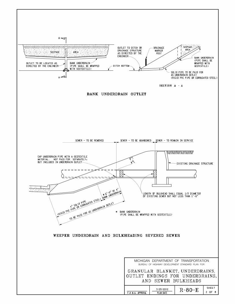
WEEPER UNDERDRAIN AND BULKHEADING SEVERED SEWER
DITCH BOTTOM
SECTION A - A
A
A
BANK UNDERDRAIN OUTLET
2 8
AND SEWER BULKHEADS
OUTLET ENDINGS FOR UNDERDRAINS,
GRANULAR BLANKET, UNDERDRAINS,
(RIGID PVC PIPE OR CORRUGATED STEEL)
AS UNDERDRAIN OUTLET
SOLID PIPE TO BE PAID FOR
GEOTEXTILE)
WRAPPED WITH
(PIPE SHALL BE
BANK UNDERDRAIN
POST
MARKER
DRAINAGEAREA
SEEPAGE
ENGINEER
AS DIRECTED BY THE
DRAINAGE STRUCTURE
OUTLET TO DITCH OR
SEEPAGE AREA
DIRECTED BY THE ENGINEER
OUTLET TO BE LOCATED AS
WITH GEOTEXTILE)
(PIPE SHALL BE WRAPPED
BANK UNDERDRAIN
SEWER - TO REMAIN IN SERVICESEWER - TO BE ABANDONEDSEWER - TO BE REMOVED
TO BE P
AID FOR AS UNDERDRAIN OUTLET
EXISTING DRAINAGE STRUCTURE
OF EXISTING SEWER BUT NOT LESS THAN 1’-0"
LENGTH OF BULKHEAD SHALL EQUAL 1/3 DIAMETER
BUT INCLUDED IN UNDERDRAIN OUTLET
MATERIAL. NOT PAID FOR SEPARATELY,
CAP UNDERDRAIN PIPE WITH A GEOTEXTILE
(PIPE SHALL BE WRAPPED WITH GEOTEXTILE)
* BANK UNDERDRAIN
2’-0"
BANK UNDERDRAIN
* 6’-0
" OF 4"
(RIGID PVC P
IPE OR CORRUGATED S
TEEL)
4" SOLID P
IPE
R-80-E
MICHIGAN DEPARTMENT OF TRANSPORTATION
OF
SHEET
PLAN DATEF.H.W.A. APPROVAL
BUREAU OF HIGHWAY DEVELOPMENT STANDARD PLAN FOR
3-29-2012

BANK UNDERDRAINS
BANK UNDERDRAIN, OPEN-GRADED
3 8
AND SEWER BULKHEADS
OUTLET ENDINGS FOR UNDERDRAINS,
GRANULAR BLANKET, UNDERDRAINS,
MICHIGAN DEPARTMENT OF TRANSPORTATION
OF
SHEET
PLAN DATEF.H.W.A. APPROVAL
BUREAU OF HIGHWAY DEVELOPMENT STANDARD PLAN FOR
BY THE ENGINEER
EXISTING GROUND
4’-0"
MA
X.
TOP OF SLOPE
OPEN-GRADED AGGREGATE 34-R
(PIPE NOT WRAPPED)
BANK UNDERDRAIN
SEEPAGE PLANE
PERVIOUS SOIL
MI
N.
DISTANCE AS DIRECTED
GEOTEXTILE BLANKET
TRENCH SHALL BE LINED WITH
12" MIN., 16" MAX. FOR 6" DIA. PIPE
8" MIN., 12" MAX. FOR 4" DIA. PIPE
PIPE DIA. + � PIPE DIA. EACH SIDE MIN.
1" - 2"
1’-0"
1’-0"
OVERLAP
6" MINIMUM
6’-0"
MA
X.
DISTANCE AS DIRECTEDDISTANCE AS DIRECTED
BY THE ENGINEER BY THE ENGINEER
EXISTING GROUND
6’-0"
MA
X.
MI
N.
TOP OF SLOPE
SEEPAGE PLANE
PERVIOUS SOIL
WITH GEOTEXTILE)
(PIPE SHALL BE WRAPPED
BANK UNDERDRAIN
GEOTEXTILE)
(PIPE SHALL BE WRAPPED WITH
BANK UNDERDRAIN (SLOPE POSITION)
ON PLANS. (TYP.)
SEED, AND MULCH AS SPECIFIED
SOD AND TOPSOIL OR TOPSOIL,
ON PLANS
SPECIFIED
SLOPE AS
MI
N.
1’-0"
3’-0"
MI
N. 1’-0"
(SEE SLOPE POSITION)
EXCEEDS 6’-0"
SLOPE IF THIS DIMENSION
TRENCH TO BE PLACED IN
12" MIN., 16" MAX. FOR 6" DIA. PIPE
8" MIN., 12" MAX. FOR 4" DIA. PIPE
PIPE DIA. + � PIPE DIA. EACH SIDE MIN.
3-29-2012 R-80-E
CLASS II AA
GRANULAR MATERIAL
CLASS II AA
GRANULAR MATERIAL
CLASS II
GRANULAR MATERIAL

SUBGRADE UNDERDRAIN
SUBBASE UNDERDRAIN
SUBGRADE UNDERDRAIN - OPEN-GRADED
4 8
AND SEWER BULKHEADS
OUTLET ENDINGS FOR UNDERDRAINS,
GRANULAR BLANKET, UNDERDRAINS,
MICHIGAN DEPARTMENT OF TRANSPORTATION
OF
SHEET
PLAN DATEF.H.W.A. APPROVAL
BUREAU OF HIGHWAY DEVELOPMENT STANDARD PLAN FOR
12" MIN., 16" MAX. FOR 6" DIA. PIPE
8" MIN., 12" MAX. FOR 4" DIA. PIPE
PIPE DIA. + � PIPE DIA. EACH SIDE MIN.
� OF LANE WIDTH
TRENCH
CENTER OF
JOINT LINE
LONGITUDINAL
IN THE CENTER OF A LANE
ARE REQUIRED, THEY SHALL BE PLACED
WHEN ADDITIONAL SUBBASE UNDERDRAINS
PAVEMENT
EDGE OF
2"
MI
N.
WITH GEOTEXTILE)
(PIPE SHALL BE WRAPPED
SUBBASE UNDERDRAIN
SHOULDERPAVEMENT
SUBGRADE
SUBBASE (DEPTH AS SPECIFIED ON PLANS)
DENSE GRADED AGGREGATE3’-0" 0R AS SPECIFIED ON PLANS
12" MIN., 16" MAX. FOR 6" DIA. PIPE
8" MIN., 12" MAX. FOR 4" DIA. PIPE
PIPE DIA. + � PIPE DIA. EACH SIDE MIN.
SUBGRADE OR AS SPECIFIED ON PLANS
A MAXIMUM OF 10" BELOW TOP OF
FLOW LINE ELEVATION NORMALLY
UN
LE
SS
OT
HE
RWI
SE
SP
ECI
FI
ED
4’-0" UNLESS OTHERWISE SPECIFIED
PAVEMENT
EDGE OF
WITH GEOTEXTILE)
(PIPE SHALL BE WRAPPED
SUBGRADE UNDERDRAIN
SHOULDERPAVEMENT
SUBGRADE
SUBBASE (DEPTH AS SPECIFIED ON PLANS)
SLOPE AS SPECIFIED ON PLANS
DENSE GRADED AGGREGATE
AP
PR
OX.
5’-
0"
DE
EP
FL
OW
LI
NE
EL
EV
ATI
ON
12" MIN., 16" MAX. FOR 6" DIA. PIPE
8" MIN., 12" MAX. FOR 4" DIA. PIPE
PIPE DIA. + � PIPE DIA. EACH SIDE MIN.
SHOULDERPAVEMENT
SUBGRADE
UN
LE
SS
OT
HE
RWI
SE
SP
ECI
FI
ED
4’-0" UNLESS OTHERWISE SPECIFIED
PAVEMENT
EDGE OF
OPEN-GRADED AGGREGATE 34-R
(PIPE SHALL NOT BE WRAPPED)
SUBGRADE UNDERDRAIN
SUBBASE (DEPTH AS SPECIFIED ON PLANS)
SLOPE AS SPECIFIED ON PLANS
DENSE GRADED AGGREGATE
GEOTEXTILE BLANKET
TRENCH SHALL BE LINED WITH
6" MINIMUM OVERLAP
AP
PR
OX.
5’-
0"
DE
EP
FL
OW
LI
NE
EL
EV
ATI
ON
1" - 2"
3-29-2012 R-80-E
GRANULAR MATERIAL CLASS II AA
GRANULAR MATERIAL CLASS II AA
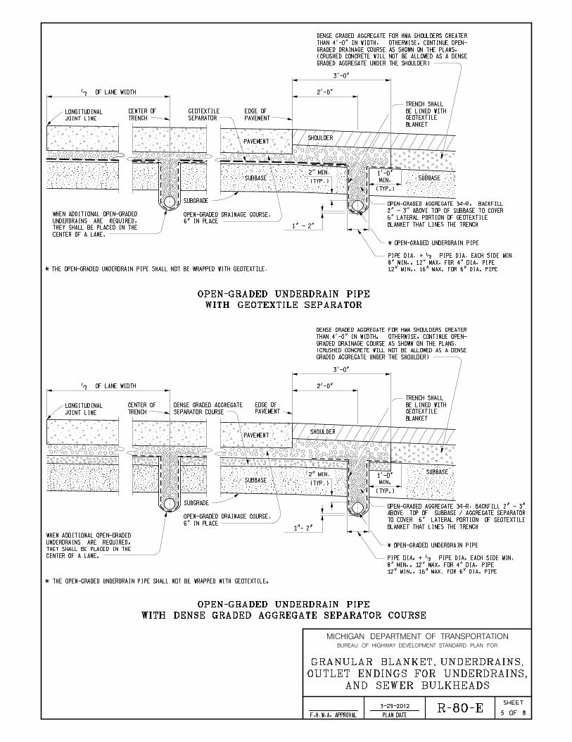
WITH GEOTEXTILE SEPARATOR
OPEN-GRADED UNDERDRAIN PIPE
WITH DENSE GRADED AGGREGATE SEPARATOR COURSE
OPEN-GRADED UNDERDRAIN PIPE
5 8
AND SEWER BULKHEADS
OUTLET ENDINGS FOR UNDERDRAINS,
GRANULAR BLANKET, UNDERDRAINS,
MICHIGAN DEPARTMENT OF TRANSPORTATION
OF
SHEET
PLAN DATEF.H.W.A. APPROVAL
BUREAU OF HIGHWAY DEVELOPMENT STANDARD PLAN FOR
SHOULDER
(TYP.)
SUBBASE SUBBASE
PAVEMENT
SEPARATOR
GEOTEXTILE
SUBGRADE
PAVEMENT
EDGE OF
*
� OF LANE WIDTH
TRENCH
CENTER OF
(TYP.)
2" MIN.
CENTER OF A LANE.
THEY SHALL BE PLACED IN THE
UNDERDRAINS ARE REQUIRED,
WHEN ADDITIONAL OPEN-GRADED
JOINT LINE
LONGITUDINAL
THE OPEN-GRADED UNDERDRAIN PIPE SHALL NOT BE WRAPPED WITH GEOTEXTILE.
BLANKET
GEOTEXTILE
BE LINED WITH
TRENCH SHALL
* OPEN-GRADED UNDERDRAIN PIPE
3’-0"
2’-0"
1" - 2"
MIN.
1’-0"
12" MIN., 16" MAX. FOR 6" DIA. PIPE
8" MIN., 12" MAX. FOR 4" DIA. PIPE
PIPE DIA. + � PIPE DIA. EACH SIDE MIN.
BLANKET THAT LINES THE TRENCH
6" LATERAL PORTION OF GEOTEXTILE
2" - 3" ABOVE TOP OF SUBBASE TO COVER
OPEN-GRADED AGGREGATE 34-R, BACKFILL
SHOULDER
(TYP.)
SUBBASE
SUBBASE
PAVEMENT
SUBGRADE
PAVEMENT
EDGE OF
� OF LANE WIDTH
TRENCH
CENTER OF
JOINT LINE
LONGITUDINAL
*
SEPARATOR COURSE
DENSE GRADED AGGREGATE
CENTER OF A LANE.
THEY SHALL BE PLACED IN THE
UNDERDRAINS ARE REQUIRED,
WHEN ADDITIONAL OPEN-GRADED
THE OPEN-GRADED UNDERDRAIN PIPE SHALL NOT BE WRAPPED WITH GEOTEXTILE.
BLANKET
GEOTEXTILE
BE LINED WITH
TRENCH SHALL
* OPEN-GRADED UNDERDRAIN PIPE
(TYP.)
2" MIN.
12" MIN., 16" MAX. FOR 6" DIA. PIPE
8" MIN., 12" MAX. FOR 4" DIA. PIPE
PIPE DIA. + � PIPE DIA. EACH SIDE MIN.
3’-0"
2’-0"
MIN.
1’-0"
1"- 2" BLANKET THAT LINES THE TRENCH
TO COVER 6" LATERAL PORTION OF GEOTEXTILE
ABOVE TOP OF SUBBASE / AGGREGATE SEPARATOR
OPEN-GRADED AGGREGATE 34-R, BACKFILL 2" - 3"
GRADED AGGREGATE UNDER THE SHOULDER)
(CRUSHED CONCRETE WILL NOT BE ALLOWED AS A DENSE
GRADED DRAINAGE COURSE AS SHOWN ON THE PLANS.
THAN 4’-0" IN WIDTH. OTHERWISE, CONTINUE OPEN-
DENSE GRADED AGGREGATE FOR HMA SHOULDERS GREATER
GRADED AGGREGATE UNDER THE SHOULDER)
(CRUSHED CONCRETE WILL NOT BE ALLOWED AS A DENSE
GRADED DRAINAGE COURSE AS SHOWN ON THE PLANS.
THAN 4’-0" IN WIDTH. OTHERWISE, CONTINUE OPEN-
DENSE GRADED AGGREGATE FOR HMA SHOULDERS GREATER
3-29-2012 R-80-E
6" IN PLACE
OPEN-GRADED DRAINAGE COURSE,
6" IN PLACE
OPEN-GRADED DRAINAGE COURSE,

WITH GEOTEXTILE SEPARATOR
OPEN-GRADED UNDERDRAIN ( PDS )
WITH DENSE GRADED AGGREGATE SEPARATOR COURSE
OPEN-GRADED UNDERDRAIN ( PDS )
6 8
AND SEWER BULKHEADS
OUTLET ENDINGS FOR UNDERDRAINS,
GRANULAR BLANKET, UNDERDRAINS,
MICHIGAN DEPARTMENT OF TRANSPORTATION
OF
SHEET
PLAN DATEF.H.W.A. APPROVAL
BUREAU OF HIGHWAY DEVELOPMENT STANDARD PLAN FOR
GRADED AGGREGATE UNDER THE SHOULDER)
(CRUSHED CONCRETE WILL NOT BE ALLOWED AS A DENSE
GRADED DRAINAGE COURSE AS SHOWN ON THE PLANS.
THAN 4’-0" IN WIDTH. OTHERWISE, CONTINUE OPEN-
DENSE GRADED AGGREGATE FOR HMA SHOULDERS GREATER
GRADED AGGREGATE UNDER THE SHOULDER)
(CRUSHED CONCRETE WILL NOT BE ALLOWED AS A DENSE
GRADED DRAINAGE COURSE AS SHOWN ON THE PLANS.
THAN 4’-0" IN WIDTH. OTHERWISE, CONTINUE OPEN-
DENSE GRADED AGGREGATE FOR HMA SHOULDERS GREATER
THE CENTER OF A LANE.
ARE REQUIRED, THEY SHALL BE PLACED IN
WHEN ADDITIONAL OPEN-GRADED UNDERDRAINS
AND TO PROTECT THE PDS FILTER COVER
SUBBASE TO COVER 6" LATERAL PORTION OF GEOTEXTILE SEPARATOR
* OPEN-GRADED AGGREGATE 34-R, BACKFILL 2" - 3" ABOVE TOP OF
PAVEMENT
SEPARATOR
GEOTEXTILE
SUBGRADE
SHOULDER
SUBBASE
* 3" MIN. - 6" MAX.
TRENCH WIDTH
2"
MI
N.
2" MIN.
2�
"
MA
X.
PAVEMENT
EDGE OF
SUBBASE
2’-0"
SUBBASE
PAVEMENT
SUBGRADE
SHOULDER
SUBBASE
* 3" MIN. - 6" MAX.
TRENCH WIDTH
2"
MI
N.
2" MIN.
2�
"
MA
X.
PAVEMENT
EDGE OF
THE CENTER OF A LANE.
ARE REQUIRED, THEY SHALL BE PLACED IN
WHEN ADDITIONAL OPEN-GRADED UNDERDRAINS
SEPARATOR COURSE
DENSE GRADED AGGREGATE
THE PDS FILTER COVER
ABOVE TOP OF DENSE GRADED AGGREGATE TO PROTECT
* OPEN-GRADED AGGREGATE 34-R, BACKFILL 2" - 3"
2’-0"
3-29-2012 R-80-E
6" IN PLACE
OPEN-GRADED DRAINAGE COURSE,
6" IN PLACE
OPEN-GRADED DRAINAGE COURSE,

PLAN SHOWING OUTLETS FOR UNDERDRAINS
DETAIL
REINFORCED EDGE
DETAIL
CONNECTOR BRACKET
STEEL END SECTION FOR 4" OR 6" PIPE
( )
7 8
AND SEWER BULKHEADS
OUTLET ENDINGS FOR UNDERDRAINS,
GRANULAR BLANKET, UNDERDRAINS,
MICHIGAN DEPARTMENT OF TRANSPORTATION
OF
SHEET
PLAN DATEF.H.W.A. APPROVAL
BUREAU OF HIGHWAY DEVELOPMENT STANDARD PLAN FOR
BY THE ENGINEER.
THE CURRENT SPECIFICATIONS OR AS APPROVED
90° ARC. CONNECTION SHALL BE ACCORDING TO
BEND 5’-0" LENGTH OF UNDERDRAIN PIPE TO A
END CAP (TYP.)
SA
G
MAXIMUM OUTLET SPACING 300’ (TYP.)
LOWEST ELEVATION OF ALL VERTICAL CURVES
ADDITIONALLY, LOCATE OUTLETS AT THE
OUTLET ENDING (TYP.)
(RIGID PVC OR CORRUGATED STEEL)
UNDERDRAIN OUTLET PIPE
BRACKET (TYP.)
STEEL FOR CONNECTOR
�" x 1" x 2�"
�"
�"
1"
1�"
GALV. ROD
�" DIA.
DIA. HOLE
\ �"
BOLT AND NUT
�" X 2�" GALVANIZED
REINFORCED EDGE
SPOT WELDS
RIVETS, BOLTS, OR EQUIVALENT
SECURED USING �" GALVANIZED
CORNER PLATES TO BE TIGHTLY
SECTION
METAL END
C.M.P. 9"
3"
4�" 1’-0"
1’-8�"
4�"
SKIRT LIP CORNER PLATE (TYP.)
3" x 5�"
UNDERDRAIN OUTLET
LIMITS OF
6" MAX.
4" MIN.
RODENT SCREEN
PIPE
DIA.
1 SYD SOD (TYP.)
3-29-2012 R-80-E
CLASS II AA. (TYP.)
TRENCH WITH GRANULAR MATERIAL
DISTANCE AS REQUIRED. BACKFILL
(RIGID PVC OR CORRUGATED STEEL)
UNDERDRAIN OUTLET PIPE

RODENT SCREEN
CONCRETE RING FOR 4" OR 6" PIPE
8 8
AND SEWER BULKHEADS
OUTLET ENDINGS FOR UNDERDRAINS,
GRANULAR BLANKET, UNDERDRAINS,
MICHIGAN DEPARTMENT OF TRANSPORTATION
OF
SHEET
PLAN DATEF.H.W.A. APPROVAL
BUREAU OF HIGHWAY DEVELOPMENT STANDARD PLAN FOR
NOMINAL WIRE
0.057" DIA.
UNDERDRAIN OUTLET
LIMITS OF
(TYP.)
IN
SI
DE
PI
PE
DI
A.
+
1"
MI
N.
(TYP.)
0.30" MAX. OPENING
INSIDE PIPE DIA. + 3" MIN.
CORRUGATIONS FOR CONNECTING THE END SECTION.
HAVE THE ENDS OF THE PIPE REROLLED TO FORM ANNULAR
HELICALLY CORRUGATED PIPE (EXCEPT PERFORATED PIPE) SHALL
APPROVED BY THE ENGINEER.
BY STANDARD METAL BANDS, OR BY OTHER CONNECTING DEVICES AS
CORRUGATED METAL PIPE AS SPECIFIED ON THIS STANDARD PLAN,
STEEL END SECTIONS SHALL BE ATTACHED TO THE ENDS OF
OUTLET PIPE.
AROUND THE SAME TYPE OF PIPE AS THAT USED FOR UNDERDRAIN
THE CONCRETE RING OR CONCRETE END SECTION SHALL BE CAST
METAL ONLY.
UNDERDRAIN OUTLET PIPE SHALL BE RIGID PVC OR CORRUGATED
STRUCTURES.
ACCORDING TO CURRENT STANDARD SPECIFICATIONS FOR DRAINAGE
OUTLET CONNECTIONS TO DRAINAGE STRUCTURES SHALL BE
TIGHT, AND OF THE SAME MATERIAL AS THE OUTLET PIPE.
THE CURRENT STANDARD SPECIFICATIONS. THEY SHALL BE WATER
ACCORDING TO APPLICABLE ASTM SPECIFICATIONS REFERENCED IN
CONNECTIONS, IF REQUIRED WITHIN THE OUTLET PIPE, SHALL BE
SPECIFICATION AND AS APPROVED BY THE ENGINEER.
PIPE SHALL BE CONSTRUCTED ACCORDING TO THE CURRENT STANDARD
CONNECTIONS BETWEEN UNDERDRAIN PIPE AND UNDERDRAIN OUTLET
UNDERDRAIN PIPE SIZES SHALL BE AS SPECIFIED ON THE PLANS.
UNDERDRAIN OUTLETS.
POSITIVE DRAINAGE SHALL BE PROVIDED FOR UNDERDRAINS AND
NOTES:
COMPATIBLE WITH PIPE
APPROVED CONNECTION
1’-0"
11"
WALL THICKNESS
2" MIN.
4"
2’-0"
10"
1’-0"
MIN.
PIPE
OUTLET
3"
(TYP.)
DIA.
PIPE
SOD
4"
MI
N.
45°
�" RADIUS
6" MAX.
4" MIN.
3’-0"
LIMITS OF UNDERDRAIN OUTLET
1’-0"
MIN.
OUTLET PIPE
COMPATIBLE WITH PIPE
APPROVED CONNECTION
45°
RODENT SCREEN
3-29-2012 R-80-E
4" MIN.
6" MAX.
RODENT SCREEN
FOR 4" OR 6" PIPE
CONCRETE END SECTION

MICHIGAN DESIGN MANUAL ROAD DESIGN CHAPTER 3 ALIGNMENT AND GEOMETRICS INDEX (continued) 3.09.04 Bridges 3.09.05 Guidelines for Passing Relief Lanes
A. General B. Truck Climbing Lanes C. Passing Lane Sections
3.10 NON-FREEWAY RECONSTRUCTION / NEW CONSTRUCTION (4R) 3.10.01 General 3.10.02 Design Criteria 3.10.03 Design Exceptions 3.11 FREEWAY RESURFACING, RESTORATION, REHABILITATION AND RECONSTRUCTION / NEW CONSTRUCTION (3R/4R) DESIGN CRITERIA 3.11.01 General 3.11.02 Freeway 3R/4R Checklist
A. Section Deleted B. Geometrics and Signing C. Section Deleted D. Design Exceptions
3.11.03 Safety Considerations
A. Section Deleted B. Ramp Geometrics and Taper Lengths C. Vertical Curbs D. Sight Distances E. Crown Location/Pavement Cross Slope F. Superelevation G. Guardrail and Concrete Barrier H. Attenuation I. Shoulder Cross Slopes J. Section Deleted (information moved to Section 3.12) K. Clear Zones & Fixed Objects L. Culvert End Treatments M. Bridges

MICHIGAN DESIGN MANUAL ROAD DESIGN 3.11.03 (revised 4-23-2012) Safety Considerations A. Section Deleted B. Ramp Geometrics and Taper Lengths When existing acceleration lanes, deceleration lanes and tapers are shorter than those shown in current MDOT guides, they should be lengthened to conform with the latest Geometric Design Guides. If these distances cannot be achieved, design exceptions are required. Normally, it is more cost effective to use the parallel design for on and off ramps. The need for additional lanes on the off ramp terminals should be analyzed for capacity improvements. Radii should be checked for adequacy. Gore areas should be flattened where desirable. C. Vertical Curbs Vertical curb should be entirely removed on freeway mainlines, high speed turning roadways and collector distributor roads. It should also be removed on other ramps for a minimum distance of 200 feet from the bifurcation or ramp nose.
3.11.03 (continued) D. Sight Distances Vertical and horizontal sight distances along the mainline and within the entire interchange area, including ramp terminals, should be reviewed for conformance with current AASHTO guides. See MDOT Sight Distance Guidelines for more detailed discussion on sight distances. E. Crown Location/Pavement Cross Slope Where resurfacing is less than 4", the crown point will be retained in its existing location, but the 2.0% cross slope should be established or maintained. Where resurfacing is 4" or more, the crown point should be moved to meet current standards by shifting it to the left edge of the outside lane. The 2.0% cross slope should be attained with the total yield kept close to 440 lbs/syd for 4", 550 lbs/syd for 5", etc. by reducing thickness on the median lane. However, this concept of relocating the crownline may not be feasible when the entire pavement is sloped in one direction. The desirable roll-over or algebraic difference between the pavement and shoulder cross slopes is six percent or less. A design exception is required when an existing parabolic crown is retained. Also, see Section 6.03.04B(1) “Crown and Superelevation Modification.” F. Superelevation Current Standard Plan R-107-Series should be used to upgrade rural freeway projects, when feasible. When it is not possible to use the current Standard Plan R-107-Series, the straight line method may be considered on a curve by curve basis as needed. See Superelevation Using A Straight Line Method in Section 3.04.03. A design exception is required if neither of these options can be met.

ROAD DESIGN MANUAL
ROAD DESIGN 7.01.10 (10-20-2008) Clear Zone – History For a number of years road designers and safety authorities considered 30' a desirable requirement for a safe roadside free of obstacles. This was based upon a study by General Motors in the early 1960's which revealed that of 211 cases at the proving grounds involving vehicles leaving the road, 80% did not travel more than 29' from the edge of pavement. The 1967 “Yellow Book” (Highway Design and Operational Practices Related to Highway Safety, AASHTO), page 20, rounded this distance off to 30'. The 2nd edition of the “Yellow Book”, published in 1974, reiterated the 30' distance, but called for an application of engineering judgement by emphasizing that the "30' distance is not a “magic number" (page 38). The 1977 Barrier Guide defined clear zone, in the glossary on page iv, as "That roadside border area, starting at the edge of the traveled way, available for safe use by errant vehicles. Establishment of a minimum width clear zone implies that rigid objects and certain other features with clearances less than the minimum width should be removed, relocated to an inaccessible position outside the minimum clear zone, or remodeled to make safely traversable, breakaway, or shielded." The 1977 Barrier Guide introduced the concept that rate of sideslope, speed of traffic, horizontal curvature, and ADT would affect the width of clear zone. The 30' width was retained for 60 mph speed in combination with flat side slopes, tangent roadway alignment, and ADT exceeding 6,000. However, a graph on page 16 adjusts this basic 30' for traffic speed and rate of sideslope. These adjustments are both up or down (wider or narrower) for either descending or ascending slope. A formula on page 17 further adjusts the clear zone for horizontal curvature. Finally, a procedure shown on pages 60-65 adjusts the clear zone downward (narrower) for ADT's below 6,000. The Supplement to the 1977 Barrier Guide expanded on the clear
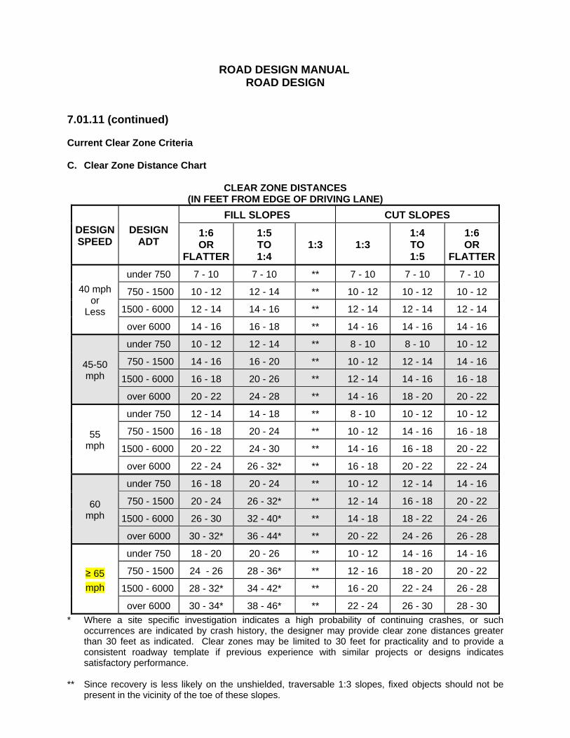
7.01.10 (continued) zone criteria that begins on page 15 of the Barrier Guide by including a series of tables prepared by the state of Illinois that show clear zone requirements for various degrees of curve. These criteria have been criticized by a number of states because of the extreme clear zone widths, particularly for the combination of sharp curve, higher speed, high traffic volume and steep slope. In anticipation of a proposed revision of the 1977 Barrier Guide, FHWA in April 1986 afforded the states a measure of relief with respect to clear zone requirements. It provided a formula for a curve correction factor that is based upon increasing the value for clear zone for a tangent section, obtained from the Barrier Guide. This new formula is more reasonable than the formula on page 17 of the Barrier Guide. It was adopted by the Department in July 1986. In 1989 the Roadside Design Guide was issued by AASHTO and adopted by MDOT as a guide. Updates to the Roadside Design Guide were published in 1996, 2002 and 2006. 7.01.11 (revised 4-23-2012) Current Clear Zone Criteria Virtually everyone agrees that a flat, smooth, unobstructed area adjacent to the driving lanes is highly desirable and significantly improves roadside safety. The only point of contention is how wide to make this area. The designer needs to understand that the clear zone distance is not an absolute number. Some designers have erroneously believed, that in all cases, the need for protecting motorists ends at the selected clear zone distance. The Department has adopted the clear zone distances from Table 3.1 on pages 3-5 and 3-6 and curve corrections from Table 3.2 on page 3-7 of the 2006 AASHTO, Roadside Design Guide. These tables have been reproduced at the end of this section.
ROAD DESIGN MANUAL
ROAD DESIGN
7.01.11 (continued) Current Clear Zone Criteria C. Clear Zone Distance Chart
CLEAR ZONE DISTANCES (IN FEET FROM EDGE OF DRIVING LANE)
DESIGN SPEED
DESIGN ADT
FILL SLOPES CUT SLOPES
1:6 OR
FLATTER
1:5 TO 1:4
1:3 1:3 1:4 TO 1:5
1:6 OR
FLATTER
40 mph or
Less
under 750 7 - 10 7 - 10 ** 7 - 10 7 - 10 7 - 10
750 - 1500 10 - 12 12 - 14 ** 10 - 12 10 - 12 10 - 12
1500 - 6000 12 - 14 14 - 16 ** 12 - 14 12 - 14 12 - 14
over 6000 14 - 16 16 - 18 ** 14 - 16 14 - 16 14 - 16
45-50 mph
under 750 10 - 12 12 - 14 ** 8 - 10 8 - 10 10 - 12
750 - 1500 14 - 16 16 - 20 ** 10 - 12 12 - 14 14 - 16
1500 - 6000 16 - 18 20 - 26 ** 12 - 14 14 - 16 16 - 18
over 6000 20 - 22 24 - 28 ** 14 - 16 18 - 20 20 - 22
55 mph
under 750 12 - 14 14 - 18 ** 8 - 10 10 - 12 10 - 12
750 - 1500 16 - 18 20 - 24 ** 10 - 12 14 - 16 16 - 18
1500 - 6000 20 - 22 24 - 30 ** 14 - 16 16 - 18 20 - 22
over 6000 22 - 24 26 - 32* ** 16 - 18 20 - 22 22 - 24
60 mph
under 750 16 - 18 20 - 24 ** 10 - 12 12 - 14 14 - 16
750 - 1500 20 - 24 26 - 32* ** 12 - 14 16 - 18 20 - 22
1500 - 6000 26 - 30 32 - 40* ** 14 - 18 18 - 22 24 - 26
over 6000 30 - 32* 36 - 44* ** 20 - 22 24 - 26 26 - 28
≥ 65 mph
under 750 18 - 20 20 - 26 ** 10 - 12 14 - 16 14 - 16
750 - 1500 24 - 26 28 - 36* ** 12 - 16 18 - 20 20 - 22
1500 - 6000 28 - 32* 34 - 42* ** 16 - 20 22 - 24 26 - 28
over 6000 30 - 34* 38 - 46* ** 22 - 24 26 - 30 28 - 30 * Where a site specific investigation indicates a high probability of continuing crashes, or such
occurrences are indicated by crash history, the designer may provide clear zone distances greater than 30 feet as indicated. Clear zones may be limited to 30 feet for practicality and to provide a consistent roadway template if previous experience with similar projects or designs indicates satisfactory performance.
** Since recovery is less likely on the unshielded, traversable 1:3 slopes, fixed objects should not be
present in the vicinity of the toe of these slopes.

ROAD DESIGN MANUAL
ROAD DESIGN 7.01.11 (continued) Current Clear Zone Criteria D. Curve Correction Factors Table The Curve Correction Factors Table shown below shall be applied to horizontal curves 2Ε or greater. The curve correction factor (Kcz) shall be applied to the outside of curve only. The inside portion of the curve will be treated as a tangent section.
CURVE CORRECTION FACTORS (Kcz) Radius
(ft) DESIGN SPEED (mph)
40 45 50 55 60 65 70 2860 1.1 1.1 1.1 1.2 1.2 1.2 1.3 2290 1.1 1.1 1.2 1.2 1.2 1.3 1.3 1910 1.1 1.2 1.2 1.2 1.3 1.3 1.4 1640 1.1 1.2 1.2 1.3 1.3 1.4 1.5 1430 1.2 1.2 1.3 1.3 1.4 1.4 1270 1.2 1.2 1.3 1.3 1.4 1.5 1150 1.2 1.2 1.3 1.4 1.5 950 1.2 1.3 1.4 1.5 1.5 820 1.3 1.3 1.4 1.5 720 1.3 1.4 1.5 640 1.3 1.4 1.5 570 1.4 1.5 380 1.5
7.01.11 (continued) E. Other Controlling Factors For free access highways, the clear zone should ideally be the same as for controlled access highways, but often this is impossible as it would require complete reconstruction of the highway, and destruction of the existing roadside features. Clear zone may often be restricted by drives, intersections, ditches, narrow R.O.W., and other features. While it may be argued that the dynamics of a vehicle running off the road are no different on a free access road than they are on a limited access facility, it remains as a fact of life that there will always be obstacles of some description on free access roads - mailboxes, driveway embankments, trees, buildings, etc. Enormous numbers of these obstacles occur on the trunkline system.
7.01.11 (continued) Continued efforts should be made to reduce these obstacles as finances permit, even though some cannot be removed without great difficulty, because of socio-environmental considerations, e.g., mature shade trees in a west-facing front yard. However safety considerations should overrule, and if need be, even these mature shade trees may have to be removed. The designer should note that the presence of an up-slope significantly reduces the clear zone width required. It is therefore seldom necessary to remove a tree or to shield an obstacle that is located at the top of a cut-slope if the elevation of the top of slope is approximately 5'-0" to 6'-0" higher than the edge of pavement. These situations should always be checked, however.

MICHIGAN DESIGN MANUAL BRIDGE DESIGN - CHAPTER 7: LRFD
7.02.19 Slabs A. Design (8-20-2009) MDOT standard LRFD slab is designed using the following criteria: 1. The design loads for decks and deck
systems should be specified depending on the method of analysis. When the approximate strip method is used, force effects should be determined on the following basis:
a. Where primary strips are
transverse and their span does not exceed 15.0 ft., the transverse strip shall be designed for the wheels of the 32.0-kip axle.
b. Where primary strips are transverse
and their span exceeds 15.0 ft., the transverse strip shall be designed for the wheels of the 32.0-kip axle and the lane load together.
c. Where primary strips are longitudinal,
the transverse strips shall be designed for all loads specified above, including the lane load.
2. The design truck shall be positioned
transversally such that the center of any wheel load is not closer than:
a. One foot (1.0 ft.) from the face of the
curb or railing for the design of the deck overhang.
b. Two Feet ( 2.0 ft.) from the edge of the
design lane for the design of all other components.
3. Where the strip method is used, the
extreme positive moment in any deck panel between girders shall be taken to apply to all positive moment regions. The extreme negative moment over any girder shall be taken to apply to all negative moment regions.
7.02.19 (continued) 4. Top 1½” of slab is considered a wearing
surface and is not included in the design depth.
Design of deck slabs using the Empirical Design Method according to A 9.7.2 AASHTO LRFD is an approved or allowed alternative. B. Overhang Design overhang according to A 9.7.1.5 AASHTO LRFD. If the deck overhang with cantilever does not exceed 6.0 ft. from the centerline of the exterior girder to the face of a structurally continuous concrete railing, the outside row of wheel loads may be replaced with a uniformly distributed line load of 1.0 klf intensity, located 1.0 ft. from the face of the railing. (8-20-2009) For standard overhang, see Bridge Design Guides 6.29.07 through 6.29.09. Overhangs greater than standard should be avoided, if possible. If not, the slab design shall be checked in this region for negative movement. C. Slab Haunches Plans are to provide for the deck slab to be haunched at each beam to provide for variance in actual top of beams. The design should normally make allowance for a 1" uniform haunch for steel beam bridges and a 2" minimum haunch for prestressed concrete beam bridges; however, the details should show the haunch as variable. A nominal 2" haunch should be used on structures with span lengths exceeding 100'-0". To aid in the construction of the haunched slab, the plans should include bottom of slab elevations over each beam and at equal intervals across the spans. These elevations should apply at the time that all structural steel has been erected, but no other loads applied; however, they should include allowance for additional deflection due to forms, steel reinforcement, deck concrete, and railing. For additional criteria when the haunch exceeds 6” see section 7.02.20 G. and Bridge Design Guide 6.42.03A. (5-6-99) (4-23-2012)
MICHIGAN DESIGN MANUAL BRIDGE DESIGN
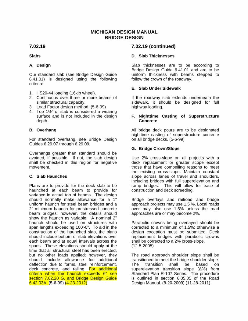
7.02.19 Slabs A. Design Our standard slab (see Bridge Design Guide 6.41.01) is designed using the following criteria: 1. HS20-44 loading (16kip wheel). 2. Continuous over three or more beams of
similar structural capacity. 3. Load Factor design method. (5-6-99) 4. Top 1½” of slab is considered a wearing
surface and is not included in the design depth.
B. Overhang For standard overhang, see Bridge Design Guides 6.29.07 through 6.29.09. Overhangs greater than standard should be avoided, if possible. If not, the slab design shall be checked in this region for negative movement. C. Slab Haunches Plans are to provide for the deck slab to be haunched at each beam to provide for variance in actual top of beams. The design should normally make allowance for a 1" uniform haunch for steel beam bridges and a 2" minimum haunch for prestressed concrete beam bridges; however, the details should show the haunch as variable. A nominal 2" haunch should be used on structures with span lengths exceeding 100'-0". To aid in the construction of the haunched slab, the plans should include bottom of slab elevations over each beam and at equal intervals across the spans. These elevations should apply at the time that all structural steel has been erected, but no other loads applied; however, they should include allowance for additional deflection due to forms, steel reinforcement, deck concrete, and railing. For additional criteria when the haunch exceeds 6” see section 7.02.20 G. and Bridge Design Guide 6.42.03A. (5-6-99) (4-23-2012)
7.02.19 (continued) D. Slab Thicknesses Slab thicknesses are to be according to Bridge Design Guide 6.41.01 and are to be uniform thickness with beams stepped to follow the crown of the roadway. E. Slab Under Sidewalk If the roadway slab extends underneath the sidewalk, it should be designed for full highway loading. F. Nighttime Casting of Superstructure
Concrete All bridge deck pours are to be designated nighttime casting of superstructure concrete on all bridge decks. (5-6-99) G. Bridge Crown/Slope Use 2% cross-slope on all projects with a deck replacement or greater scope except those that have compelling reasons to meet the existing cross-slope. Maintain constant slope across lanes of travel and shoulders, including bridges with full superelevation and ramp bridges. This will allow for ease of construction and deck screeding. Bridge overlays and railroad and bridge approach projects may use 1.5 %. Local roads over may also use 1.5% unless the road approaches are or may become 2%. Parabolic crowns being overlayed should be corrected to a minimum of 1.5%; otherwise a design exception must be submitted. Deck replacement bridges with parabolic crowns shall be corrected to a 2% cross-slope. (12-5-2005) The road approach shoulder slope shall be transitioned to meet the bridge shoulder slope. The transition shall be based on superelevation transition slope (Δ%) from Standard Plan R-107 Series. The procedure is outlined in section 6.05.05 of the Road Design Manual. (8-20-2009) (11-28-2011)
MICHIGAN DESIGN MANUAL BRIDGE DESIGN - CHAPTER 7: LRFD
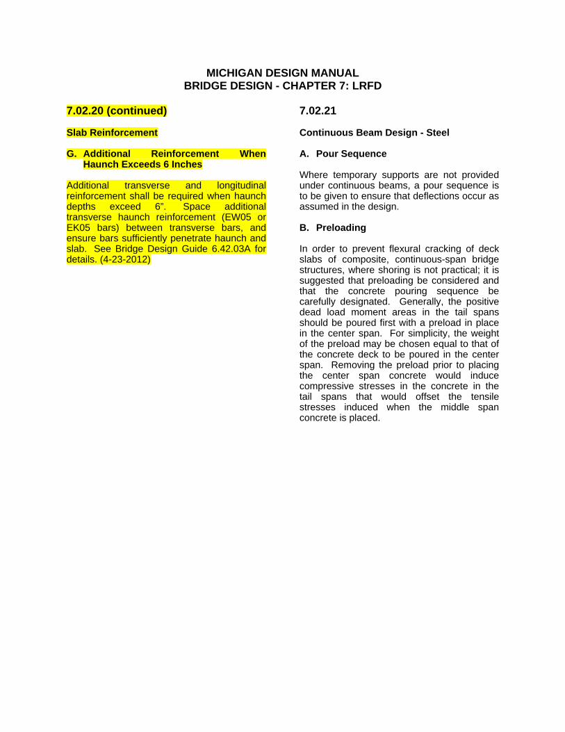
7.02.20 (continued) Slab Reinforcement G. Additional Reinforcement When
Haunch Exceeds 6 Inches Additional transverse and longitudinal reinforcement shall be required when haunch depths exceed 6”. Space additional transverse haunch reinforcement (EW05 or EK05 bars) between transverse bars, and ensure bars sufficiently penetrate haunch and slab. See Bridge Design Guide 6.42.03A for details. (4-23-2012)
7.02.21 Continuous Beam Design - Steel A. Pour Sequence Where temporary supports are not provided under continuous beams, a pour sequence is to be given to ensure that deflections occur as assumed in the design. B. Preloading In order to prevent flexural cracking of deck slabs of composite, continuous-span bridge structures, where shoring is not practical; it is suggested that preloading be considered and that the concrete pouring sequence be carefully designated. Generally, the positive dead load moment areas in the tail spans should be poured first with a preload in place in the center span. For simplicity, the weight of the preload may be chosen equal to that of the concrete deck to be poured in the center span. Removing the preload prior to placing the center span concrete would induce compressive stresses in the concrete in the tail spans that would offset the tensile stresses induced when the middle span concrete is placed.
MICHIGAN DESIGN MANUAL BRIDGE DESIGN
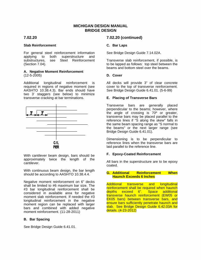
7.02.20 Slab Reinforcement For general steel reinforcement information applying to both superstructure and substructures, see Steel Reinforcement (Section 7.04). A. Negative Moment Reinforcement (12-5-2005) Additional longitudinal reinforcement is required in regions of negative moment (see AASHTO 10.38.4.3). Bar ends should have two 3’ staggers (see below) to minimize transverse cracking at bar terminations.
With cantilever beam design, bars should be approximately twice the length of the cantilever. With continuous beam design, the bar length should be according to AASHTO 10.38.4.4. Negative moment reinforcement on 6” decks shall be limited to #6 maximum bar size. The #3 bar longitudinal reinforcement shall be considered in available area for negative moment slab reinforcement. If needed the #3 longitudinal reinforcement in the negative moment region can be replaced with larger bars and combined with added negative moment reinforcement. (11-28-2011) B. Bar Spacing See Bridge Design Guide 6.41.01.
7.02.20 (continued) C. Bar Laps See Bridge Design Guide 7.14.02A. Transverse slab reinforcement, if possible, is to be lapped as follows: top steel between the beams and bottom steel over the beams. D. Cover All decks will provide 3" of clear concrete cover to the top of transverse reinforcement. See Bridge Design Guide 6.41.01. (5-6-99) E. Placing of Transverse Bars Transverse bars are generally placed perpendicular to the beams; however, where the angle of crossing is 70º or greater, transverse bars may be placed parallel to the reference lines if "S along the skew" falls in the same beam spacing range as "S normal to the beams" or the next larger range (see Bridge Design Guide 6.41.01). Dimensioning is to be perpendicular to reference lines when the transverse bars are laid parallel to the reference line. F. Epoxy-Coated Reinforcement All bars in the superstructure are to be epoxy coated. G. Additional Reinforcement When
Haunch Exceeds 6 Inches Additional transverse and longitudinal reinforcement shall be required when haunch depths exceed 6”. Space additional transverse haunch reinforcement (EW05 or EK05 bars) between transverse bars, and ensure bars sufficiently penetrate haunch and slab. See Bridge Design Guide 6.42.03A for details. (4-23-2012)

VZ
BLT
ISSUED: / /
6.42.03A
HAUNCH DETAILS
2"
HA
UN
CH
HA
UN
CH
EA04 BARS
ADDITIONAL
GUI
DE 6.41.01)
(A
S
SP
ECI
FI
ED
ON
GUI
DE 6.41.0
1)
(A
S
SP
ECI
FI
ED
ON
DECK BARS
BETWEEN TRANSVERSE
EW05 BARS SPACED
DECK BARS
BETWEEN TRANSVERSE
EW05 BARS SPACED
CO
VE
R
CL
EA
R
CO
VE
R
CL
EA
R
EA04 BARS
ADDITIONAL
TRANSVERSE STEEL
STEEL (TYP)
DISTRIBUTION
TRANSVERSE STEEL
STEEL (TYP)
DISTRIBUTION
COVER
CLEAR
1�" MIN.
3"
EXISTING BEAM
EXISTING BEAM
1’-6" 1’-6"
VA
RI
ES
VARIES
EW05 BAR
INTERIOR BEAM HAUNCH 6" DETAIL
CONVENTIONAL FORMS
METAL STAY IN PLACE FORMS
COVER
CLEAR
1�" MIN.
DECK BARS
BETWEEN TRANSVERSE
EK05* BARS SPACED
HA
UN
CH
EXISTING BEAM
2"
3"
TRANSVERSE STEEL
STEEL (TYP)
DISTRIBUTION
GUI
DE 6.41.01)
(A
S
SP
ECI
FI
ED
ON
*
T
SL
AB
EA04 BARS
ADDITIONAL
TOP OF SLAB
CONVENTIONAL FORMS
DECK BARS
BETWEEN TRANSVERSE
EK05* BARS SPACED
EXISTING BEAM
2"
3"
TRANSVERSE STEEL
STEEL (TYP)
DISTRIBUTION
GUI
DE 6.41.0
1)
(A
S
SP
ECI
FI
ED
ON
*
T
SL
AB
EA04 BARS
ADDITIONAL
TOP OF SLAB
METAL STAY IN PLACE FORMS
1’-6" MAX. 1’-6" MAX.
VARIES
VA
RI
ES
3"
MI
N.
3"
MI
N.
CLEAR COVER
3" MIN.
COVER
CLEAR
1�" MIN.
HA
UN
CH
COVER
CLEAR
1�" MIN.
INTERIOR BEAM HAUNCH 6" DETAIL
FASCIA BEAM HAUNCH 6" DETAIL
FASCIA BEAM HAUNCH 6" DETAIL
GUI
DE 6.4
2.0
3)
(A
S
SP
ECI
FI
ED
ON
GUI
DE 6.42.03)
(A
S
SP
ECI
FI
ED
ON
CLEAR COVER
3" MIN.
EK05* BAR
STEEL BEAMS SHOWN; PCI AND BOX BEAMS SIMILAR.
QUANTITY TOTALS.
WHERE LIMITS ARE UNKNOWN PROVIDE EXTRA HAUNCH REINFORCEMENT IN
SHOW LIMITS OF HAUNCH REINFORCEMENT ALONG THE LENGTH OF EACH BEAM.
DETAILS SHEET.
DETAIL HAUNCH REINFORCEMENT ON PLAN SHEETS AND STEEL REINFORCEMENT
* USE EW05 BAR WHEN OVERHANG IS GREATER THAN 1’-6"
NOTES:
WHERE THE HAUNCH EXCEEDS 6" IN DEPTH.
ADDITIONAL REINFORCEMENT SHALL BE PROVIDED IN AREAS
AMOUNT NECESSARY TO COVER THE LIMITS SHOWN ON THE PLANS.
THE HAUNCH REINFORCEMENT QUANTITY SHOWN PROVIDES THE
PLAN NOTES:
BUREAU OF HIGHWAY DEVELOPMENT
MICHIGAN DEPARTMENT OF TRANSPORTATIONDRAWN BY:
APPROVED BY: DAJ
DESIGN DIVISION
PREPARED BY
SUPERSEDES: / /
ISSUED: 04/23/12
CHECKED BY:
FA
SCI
A
THI
CK
NE
SS
"F",
"T",
SL
AB
THI
CK
NE
SS
"T",
SL
AB
THI
CK
NE
SS
FA
SCI
A
THI
CK
NE
SS
"F",
Recommended