Technical Datasheet
F-31, MIDC, Satpur, Nashik-422 007,India.Tel.: +91 253 2202160, 2202202 Fax : +91 253 2351064E-mail : India :- [email protected]
International :- [email protected]
Page 1 of 7
True RMS Measurement Trip relay cum DPM with Class 0.5 4 digit 7 segment LED display
4 different parameters on site selection Stores last 15 faults Configuration via USB-based PRKAB
Dual color LED for fault indication Detection of fault with display of parameter value
True RMS Digital Protection Relay
RISH Relay I is used to protect against Over Current, Under Current, Current Loss, Current Unbalance.
Preliminary Datasheet subject to change without notice
Ak
RISH Relay - I
RESET TEST ENTER
RISHABH
RELAY-1 RELAY-2
L3
L2
L1
Relay RISH
Current Protection Relay
- I
Version: K 05 / 07 / 18
Ak
RISH Relay - I
RESET TEST ENTER
RISHABH
RELAY-1 RELAY-2
L3
L2
L1
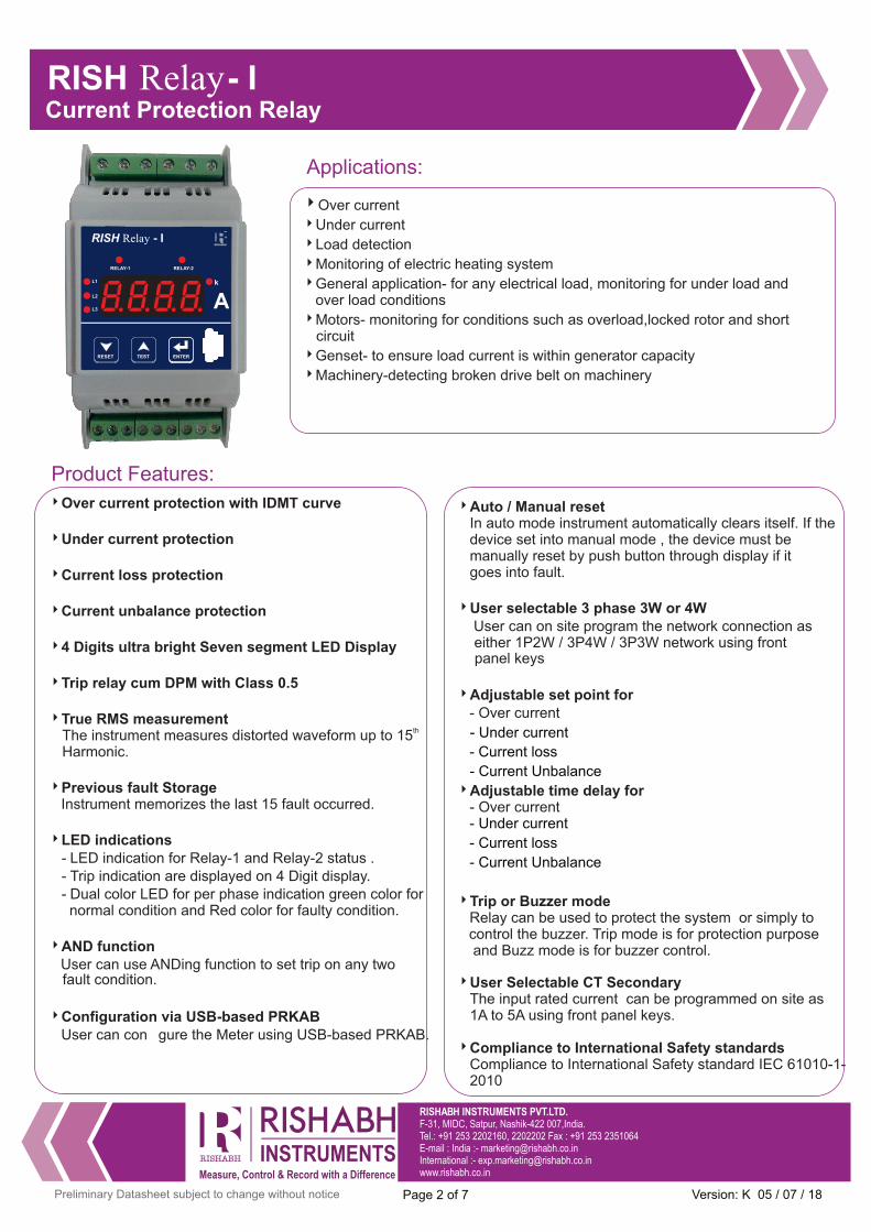
Over current
Under current
Load detection
Monitoring of electric heating system
General application- for any electrical load, monitoring for under load and over load conditions
Motors- monitoring for conditions such as overload,locked rotor and short circuit
Genset- to ensure load current is within generator capacity
Machinery-detecting broken drive belt on machinery
Applications:
Over current protection with IDMT curve
Under current protection Current loss protection
Current unbalance protection 4 Digits ultra bright Seven segment LED Display Trip relay cum DPM with Class 0.5 True RMS measurement
thThe instrument measures distorted waveform up to 15 Harmonic.
Previous fault Storage Instrument memorizes the last 15 fault occurred.
LED indications - LED indication for Relay-1 and Relay-2 status . - Trip indication are displayed on 4 Digit display. - Dual color LED for per phase indication green color for
normal condition and Red color for faulty condition.
AND function User can use ANDing function to set trip on any two
fault condition.
Configuration via USB-based PRKAB User can con gure the Meter using USB-based PRKAB.
Auto / Manual reset In auto mode instrument automatically clears itself. If the device set into manual mode , the device must be manually reset by push button through display if it goes into fault.
User selectable 3 phase 3W or 4W User can on site program the network connection as
either 1P2W / 3P4W / 3P3W network using front panel keys
Adjustable set point for - Over current
- Under current
- Current loss
- Current Unbalance
Adjustable time delay for - Over current - Under current
- Current loss
- Current Unbalance
Trip or Buzzer mode Relay can be used to protect the system or simply to
control the buzzer. Trip mode is for protection purpose and Buzz mode is for buzzer control.
User Selectable CT SecondaryThe input rated current can be programmed on site as 1A to 5A using front panel keys.
Compliance to International Safety standards
Compliance to International Safety standard IEC 61010-1- 2010
Product Features:
F-31, MIDC, Satpur, Nashik-422 007,India.Tel.: +91 253 2202160, 2202202 Fax : +91 253 2351064E-mail : India :- [email protected]
International :- [email protected]
Page 2 of 7 Preliminary Datasheet subject to change without notice
Relay RISH
Current Protection Relay
- I
Version: K 05 / 07 / 18

Input Current
Nominal Input Current (AC RMS) 5 A ----------------------------------------------------------------------------------------------------------------
System CT Secondary Values 1 A to 5 A programmable on site----------------------------------------------------------------------------------------------------------------System CT Primary Values 1 A to 999 kA programmable on site
Auxiliary Supply
Auxiliary Supply Voltage 60 V – 300V AC-DC ----------------------------------------------------------------------------------------------------------------
Aux Supply Frequency 45 to 66 Hz range
Overload Withstand
Current 20 x for 1 second, repeated 5
times at 5 min
Operating Measuring Ranges
Current Range 5...140% of CT Secondary---------------------------------------------------------------------------------------------------------------- Frequency 40...70Hz
Reference condition for Accuracy
Reference Condition 23°C +/- 2°C----------------------------------------------------------------------------------------------------------------Input waveform Sinusoidal (distortion factor 0.005)----------------------------------------------------------------------------------------------------------------Input Frequency 50 or 60 Hz ±2%----------------------------------------------------------------------------------------------------------------Auxiliary supply voltage Nominal Value ±1%----------------------------------------------------------------------------------------------------------------Auxiliary supply frequency Nominal Value ±1%----------------------------------------------------------------------------------------------------------------
Technical Specifications:
Dimensions Details:
User selectable CT primary The Primary of Current Transformer can be programmed on site from 1 A to 999 kA for Current
protection relay.
EMC Compatibility Compliance to International standard IEC 61326 - 1.
Onsite selection of Auto scroll / Fixed Screen User can set the display in auto scrolling mode or fixed screen mode using front panel keys.
ANSI Numbers:
ANSI NO. Acronyms
51
37 Under current relay
46
Over current relay
Current unbalance relay
F-31, MIDC, Satpur, Nashik-422 007,India.Tel.: +91 253 2202160, 2202202 Fax : +91 253 2351064E-mail : India :- [email protected]
International :- [email protected]
VA Burden
Input Current Burden < 0.25 VA approx. per phase
Auxiliary Supply Burden < 4 VA approx.
Higher Aux Nominal value 230 V AC/DC 50/60 Hz for AC Aux
----------------------------------------------------------------------------------------------------------------External Lower Aux 20 V – 60 VDC / 20 V – 40 VAC ----------------------------------------------------------------------------------------------------------------Lower Aux Nominal value 48 VDC / 24 VAC 50/60 Hz for AC Aux ----------------------------------------------------------------------------------------------------------------
---------------------------------------------------------------------------------------------------------------- OR
----------------------------------------------------------------------------------------------------------------
Page 3 of 7 Preliminary Datasheet subject to change without notice
Max Continuous Input Current 145% of CT Secondary----------------------------------------------------------------------------------------------------------------
Relay RISH
Current Protection Relay
- I
Version: K 05 / 07 / 18

Accuracy
Input Current ±0.5% of nominal value---------------------------------------------------------------------------------------------------------------
Trip, Reset Delays, Power ON ±140 msec or ±5% of Set Delay, Whichever is Greater (WIG)
Influence of Variations
Temperature coefficient : 0.05%/°C for current
Applicable Standards
EMC IEC 61326-1:2012, Table 2---------------------------------------------------------------------------------------------------------------
Immunity IEC 61000-4-3. 10V/m min – Level 3 industrial
Low level---------------------------------------------------------------------------------------------------------------
Safety IEC 61010-1-2010 , Permanently connected use---------------------------------------------------------------------------------------------------------------IP for water & dust IEC60529---------------------------------------------------------------------------------------------------------------
Pollution degree: 2---------------------------------------------------------------------------------------------------------------Installation category: 300V CAT III / 600V CAT II---------------------------------------------------------------------------------------------------------------
High Voltage Test 2.2 KV AC, 50Hz for 1 minute between all
Electrical circuits.
Environmental
Operating temperature -10 to +55°C---------------------------------------------------------------------------------------------------------------Storage temperature -25 to +70°C---------------------------------------------------------------------------------------------------------------Relative humidity 0... 90% non condensing---------------------------------------------------------------------------------------------------------------Shock 15g in 3 planes---------------------------------------------------------------------------------------------------------------
Vibration 10... 55 Hz, 0.15mm amplitude---------------------------------------------------------------------------------------------------------------
Enclosure IP20 (front face only)
Relay Contacts
Types of output 1CO, 2CO, 1CO+1CO---------------------------------------------------------------------------------------------------------------Contact Ratings (Res. Load) 5A/250VAC/30VDC---------------------------------------------------------------------------------------------------------------
Mechanical Endurance 1x10^7 OPS
Mechanical Attributes
Weight 300g Approx.
Electrical Connection: Technical Specifications:
1 2 3 4 5 6
7 8 9 1112 14 21 22 24
F-31, MIDC, Satpur, Nashik-422 007,India.Tel.: +91 253 2202160, 2202202 Fax : +91 253 2351064E-mail : India :- [email protected]
International :- [email protected]
11
12 14
Relay 1 Relay 2
21
22 24
Note- Relay Contacts are shown
in power off condition
COM
NC NO
COM
NC NO
Electrical Endurance NO- 3x10^4 OPS for 1CO / 1CO+1CO relay
NC- 1x10^4 OPS
1x10^5 OPS for 2CO relay
---------------------------------------------------------------------------------------------------------------Frequency ±0.2 Hz
Page 4 of 7 Preliminary Datasheet subject to change without notice
3 Phase 4 wire Unbalanced load
1 Phase 2 Wire
3 Phase 3 wire Unbalanced load
---------------------------------------------------------------------------------------------------------------
Relay RISH
Current Protection Relay
- I
1 2 3 4 5 6 7 8
L NAUX SUPPLY
L1 L2L3
L OAD
P1
S1
P1
S1
P1
S1
9
NC
1 2 3 4 5 6 7 8
L NAUX SUPPLY
L1 L2L3
L OADP1
S1
P1
S1
9
NC
1 2 3 4 5 6 7 8
L NAUX SUPPLY
L1 L2L3
L OAD
P1
S1
9
NC
Version: K 05 / 07 / 18

F-31, MIDC, Satpur, Nashik-422 007,India.Tel.: +91 253 2202160, 2202202 Fax : +91 253 2351064E-mail : India :- [email protected]
International :- [email protected]
Definite Time Characteristics: Over (OC) and Under (UC) Current
Over set (%)
Under set (%)
I off
Over set (%)
Under set (%)
I off
Differential (Hysteresis)
Pd Td Rd
Td Rd
Relay 1- OC: 11-14 (Energized)
Phase L1-LED
Phase L2-LED
Phase L3-LED
Relay-1 LED (OC)
Relay-2 LED (UC)
Aux Supply
Current Loss (C.LoS) and Current Unbalance (C.un)
Differential (Hysteresis)
Pd Td Rd
Td Rd
Over set (%)
I rated
I rated
L1
L2
L3 I rated
Under set (%)
I off
Unbalance
Unbalance
Differential (Hysteresis)
Time
Time
Note:1] Pd- Power ON delay2] Td- Trip delay3] Rd- Reset delay4] Both relay can be configured to
energize or de-energize mode5] Any relay can be assigned to any
fault condition
Energized
De-Energized
Red blinking - Trip Delay(only Phase LEDs)
Green blinking - Reset Delay(only Phase LEDs)
RED ON - fault condition
Green ON - healthy condition
Differential (Hysteresis)
Relay 2- UC: 21-24 (De-Energized)
Relay States -
Phase LED Indications -
RED ON - fault condition
Green ON - healthy condition
Relay LED Indications -
Input Absent
Page 5 of 7 Preliminary Datasheet subject to change without notice
Phase Fail set (%)
I off
Phase Fail set (%)
I off
Relay 1 - C.LoS : 11-14 (Energized)
Phase L1-LED
Phase L2-LED
Phase L3-LED
Relay-1 LED (C.LoS)
Relay-2 LED (C.Un)
Aux Supply
I rated
I rated
L1
L2
L3 I rated
Phase Fail set (%)
I off
Relay 2 - C.Un: 21-24 (De-Energized)
Relay RISH
Current Protection Relay
- I
Version: K 05 / 07 / 18

10- Reset Key : Decrements setting value, move downwards in the menu or change
11- Configuration via USB-based PRKAB.
parameter. It is also used to reset relay when manual reset mode is selected.
Parameters RISH Relay-I
Trip setting for Current loss 5 - 99%
Trip setting for Current Unbalance
1 - 15%*Setting for Differential / hysteresis
2 - 20%
Trip setting for under current
Relay control mode De-energize / Energize
Trip setting for over current (IDMT Disabled)
Reset Delay
Programmable Delay for over current 0 - 30s
Programmable Delay for under current
Programmable Delay for Current loss
Programmable Delay for current unbalance
Reset option Auto / Manual
CT primary current 1 A - 999 kA
Rated current 1 to 5 A
30 - 140%
10 - 99%
0.2 - 30s
0 - 30s
0 - 30s
0 - 30s
Parameter Settings:
1 - L1- LED : Indicates status of I1 . It Lights green when input current is healthy, red in fault condition, red blinking in trip delay and green blinking in reset delay.
2 - L2-LED : Indicates status of I2. It Lights green when input current is healthy, red in fault condition, red blinking in trip delay and green blinking in reset delay.
3 - L3- LED : Indicates status of I3. It Lights green when input current is healthy, red in fault condition, red blinking in trip delay and green blinking in reset delay.
6 - 4 Digit ultra bright 7 seg LED Display.
7 - K LED : It is used to show value in kA.
9- Test Key : Increments setting value, move upwards in the menu or change parameter. It is also used to test operation of relay. Continuous holding of test key changes relay
position and when release it resets the relay position (Only in healthy condition).
Operating elements:
F-31, MIDC, Satpur, Nashik-422 007,India.Tel.: +91 253 2202160, 2202202 Fax : +91 253 2351064E-mail : India :- [email protected]
International :- [email protected]
Note * Differential setting range for current unbalance is limited as per its setting of trip point.
4/5 - Relay-1 and Relay-2 status LED : Indicates status of relay-1 and relay-2 respectively. It lights green for relay in healthy condition and red for relay in trip condition.
8 - Enter Key : Confirms changes of parameter setting. When on the measurement screen, holding for 3 sec enters in setup menu.
Time Multiplier Setting (TMS) 0.1 - 1
Individual Faults can be deactivated as per system requirement YES
Page 6 of 7 Preliminary Datasheet subject to change without notice
Power ON Delay 0.5 - 30s
Trip setting for over current (IDMT Enabled) 30 - 125%
Relay RISH
Current Protection Relay
- I
AL3
L2
L1
RISH Relay - I
k
RELAY-1 RELAY-2
RISHABH
ENTERTESTRESET
RISHABH
1
2
3
4 6 5
7
11
9 810
k
Version: K 05 / 07 / 18
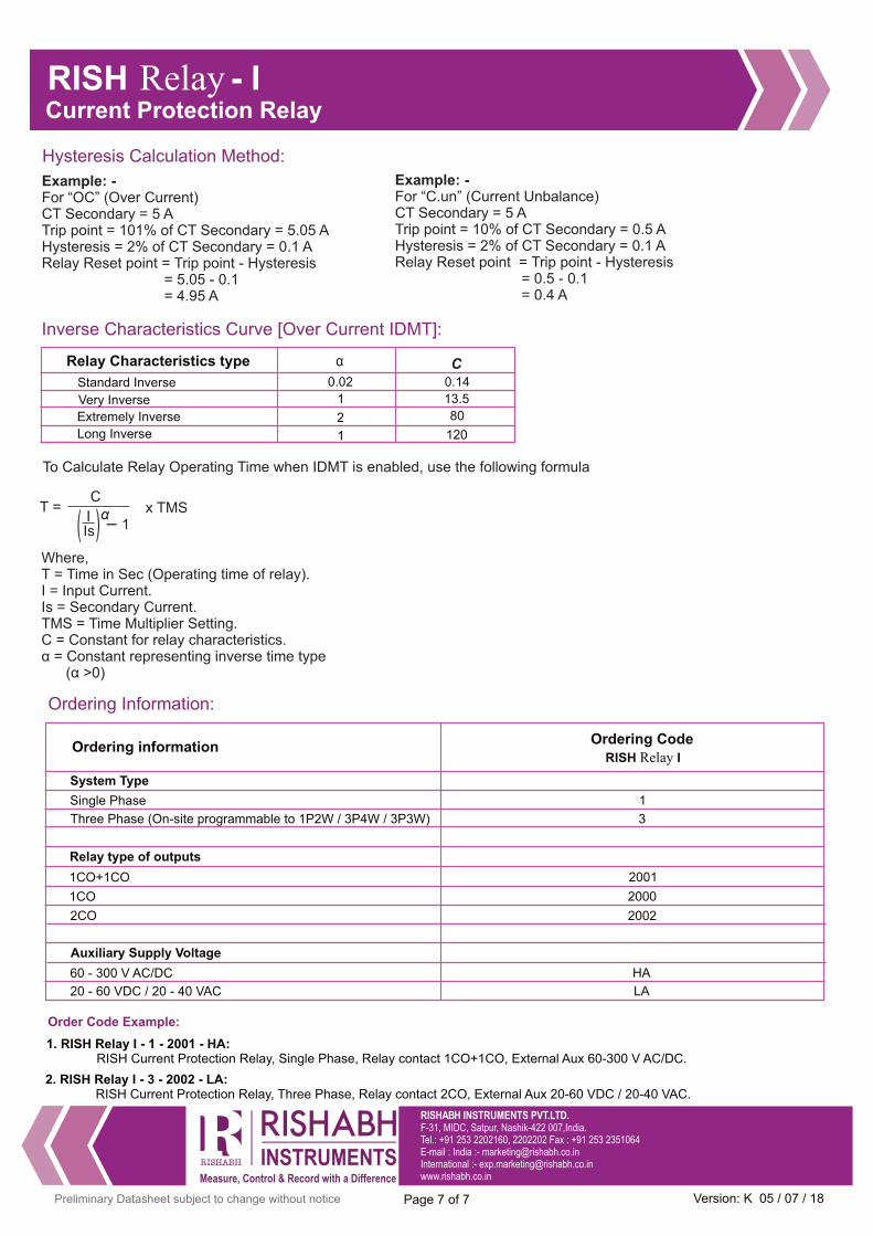
Relay Characteristics type
Inverse Characteristics Curve [Over Current IDMT]:
Very Inverse
Long Inverse
Standard Inverse
Extremely Inverse
α C0.02
1
2
1
0.14
13.5
80
120
F-31, MIDC, Satpur, Nashik-422 007,India.Tel.: +91 253 2202160, 2202202 Fax : +91 253 2351064E-mail : India :- [email protected]
International :- [email protected]
Page 7 of 7 Preliminary Datasheet subject to change without notice
To Calculate Relay Operating Time when IDMT is enabled, use the following formula
Where, T = Time in Sec (Operating time of relay).I = Input Current.Is = Secondary Current.TMS = Time Multiplier Setting.C = Constant for relay characteristics.α = Constant representing inverse time type (α >0)
T =
C I Is
-1
x TMSα))
Example: - For “OC” (Over Current) CT Secondary = 5 A .
Trip point = 101% of CT Secondary = 5.05 AHysteresis = 2% of CT Secondary = 0.1 A Relay Reset point = Trip point - Hysteresis = 5.05 - 0.1 = 4.95 A
Example: - For “C.un” (Current Unbalance) CT Secondary = 5 ATrip point = 10% of CT Secondary = 0.5 A Hysteresis = 2% of CT Secondary = 0.1 A Relay Reset point = Trip point - Hysteresis = 0.5 - 0.1 = 0.4 A
Hysteresis Calculation Method:
Ordering Information:
1. RISH Relay I - 1 - 2001 - HA: RISH Current Protection Relay, Single Phase, Relay contact 1CO+1CO, External Aux 60-300 V AC/DC.
Order Code Example:
2. RISH Relay I - 3 - 2002 - LA: RISH Current Protection Relay, Three Phase, Relay contact 2CO, External Aux 20-60 VDC / 20-40 VAC.
Ordering information Ordering Code
RISH Relay I
1CO+1CO 2001
2CO 2002
Relay type of outputs
1CO 2000
60 - 300 V AC/DC HA
Auxiliary Supply Voltage
20 - 60 VDC / 20 - 40 VAC LA
System Type
Single Phase 1
Three Phase (On-site programmable to 1P2W / 3P4W / 3P3W) 3
Relay RISH
Current Protection Relay
- I
Version: K 05 / 07 / 18
Recommended