Revision Mid 2
Prof. Sin-Min Lee
Department of Computer Science
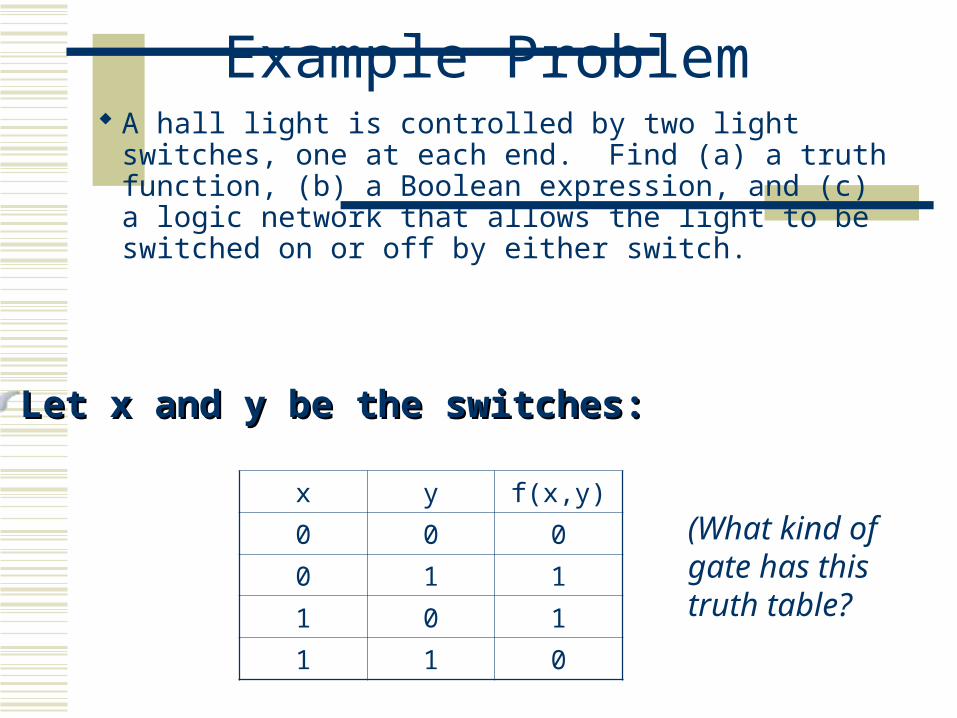
Example Problem A hall light is controlled by two light switches, one
at each end. Find (a) a truth function, (b) a Boolean expression, and (c) a logic network that allows the light to be switched on or off by either switch.
x y f(x,y)
0 0 0
0 1 1
1 0 1
1 1 0
(What kind of gate has this truth table?
Let Let xx and and yy be the switches: be the switches:
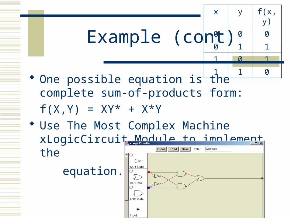
Example (cont)
One possible equation is the complete sum-of-products form:
f(X,Y) = XY* + X*Y Use The Most Complex Machine xLogicCircuit
Module to implement the
equation.
x y f(x,y)
0 0 0
0 1 1
1 0 1
1 1 0

How to use NAND gates to build an OR gate?
Truth TableA B C D Q
0 0 1 1 0
0 1 1 0 1
1 0 0 1 1
1 1 0 0 1Hint 1 : Use 3 NAND gates
Hint 2 : Use 2 NAND gates to build 2 NOT gates
Hint 3 : Put the 3rd NAND gate after the 2 “NOT” gates
A
B
C
DQ

How to use NAND gates to build a NOR gate?
Truth TableA B C D E Q
0 0 1 1 0 1
0 1 1 0 1 0
1 0 0 1 1 0
1 1 0 0 1 0
A
B
C
DQ
E
Hint 4 : Put the “NOT” gate after “OR” gate
Hint 3 : Use a NOR gate to build a NOT gate
Hint 2 : Use 3 NAND gates to build an OR gate
Hint 1 : Use 4 NAND gates


Multiplexers
A combinational circuit that selects info from one of many input lines and directs it to the output line.
The selection of the input line is controlled by input variables called selection inputs.
They are commonly abbreviated as “MUX”.


These pictures have errors.


T
CLK
Q1

T
CLK
Q1

How to use D to implement T Flip-Flop
Q
QSET
CLR
D
D = TQ’ + T’Q
T

How to use T to implement D Flip-Flop
T Q+
0
1
Q
Q’
D Q+
0
1
0
1
T = DQ’ + D’Q
Q+ 0 1
D
0
1
0 1
1 0

How to use T to implement D Flip-Flop
Q
QSET
CLR
DT
T = DQ’ + D’Q
D

Implementing with a D AND a T flip-flop
Using this FSM with three states, an operating only on inputs and transitions from one state to another, we will be using both D and T flip-flops.

Implementing with a D AND a T flip-flop
Since we have no state “11”, our Q(t+1) is “don't care” = “XX” for both of these transitions.
Consider the first column of the Q(t+1) values to be “D” and the second to be “T” and then we derive two corresponding charts.
D T

Implementing with a D AND a T flip-flop
Then we need to derive the corresponding equations.

Implementing with a D AND a T flip-flop
We assume that Q(t) is actually a pair of Q
DQ
T.
Now, with these equations, we can graph the results.

Implementing with a D AND a T flip-flop


Recommended