Resonance Control for Future SRF Accelerators
Warren SchappertResonance Control GroupFermilab
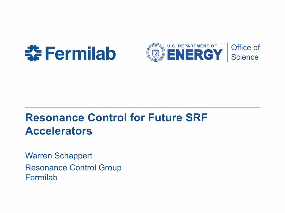
Some Future SRF Accelerators
• As cavity gradients rise matched bandwidths narrow
• Minimizing detuning is critical for narrowband machines
• PIP-II presents a unique challenge because of the narrow bandwidths and pulsed operation
http://accelconf.web.cern.ch/AccelConf/IPAC2015/talks/thzms3_talk.pdf

SRF Cavity Detuning
• SRF cavities manufactured from thin sheets of niobium to allow them to be cooled to superconducting temperatures
• Thin walls make cavities susceptible to detuning from–Pressure variations in the surrounding
helium bath–Radiation pressure from the RF field
(Lorentz Force Detuning)–External vibration sources
(microphonics)
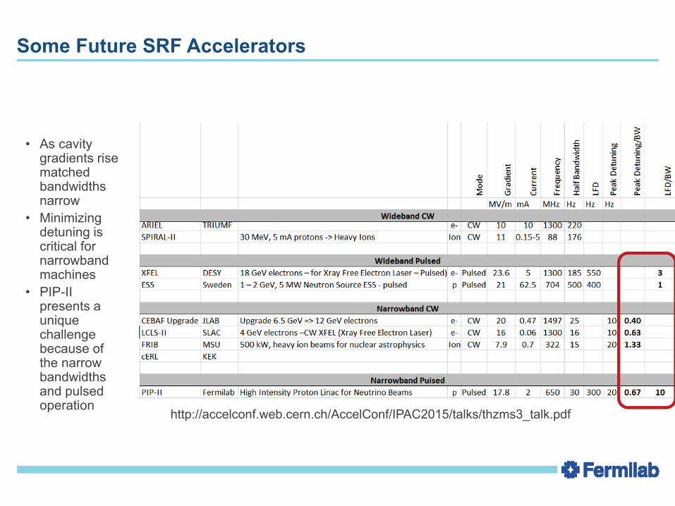
The Cost of Cavity Detuning
• Operating detuned cavities is more expensive– If sufficient RF power is not available to
maintain a constant gradient during the peak expected cavity detuning, the beam will be lost
• Cavity detuning can be a major driver of the cost of a narrow-band machine
• The cost is driven by the PEAK detuning
Delayen and Merminga, Unpublished CEBAF Report
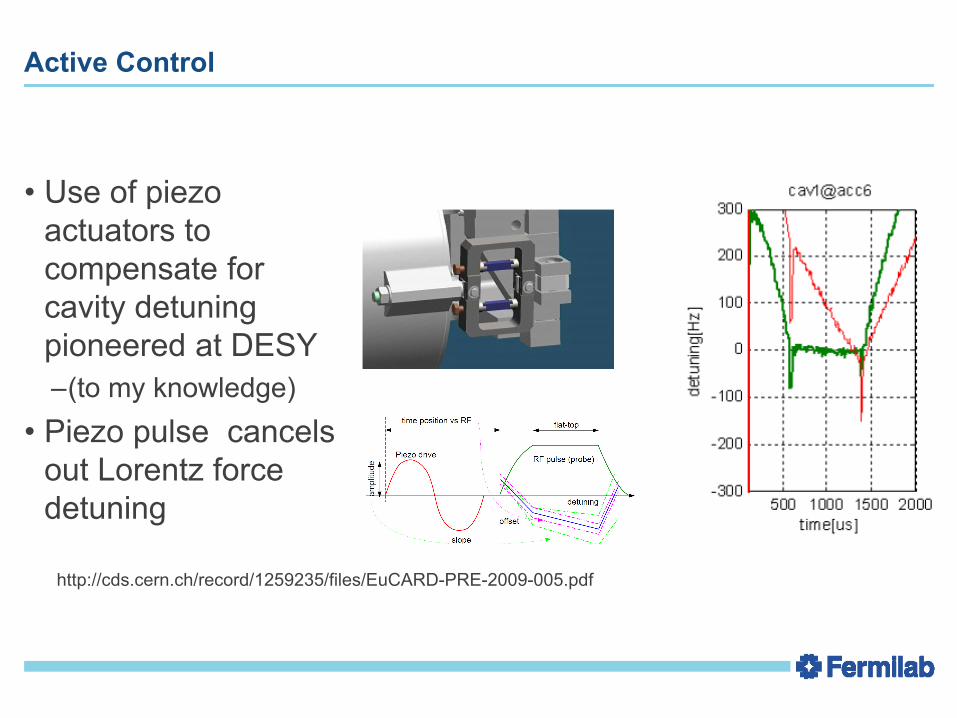
Active Control
• Use of piezo actuators to compensate for cavity detuning pioneered at DESY–(to my knowledge)
• Piezo pulse cancels out Lorentz force detuning
http://cds.cern.ch/record/1259235/files/EuCARD-PRE-2009-005.pdf

Measuring Cavity Detuning
• Cavity detuning can be determined from complex baseband cavity signals
• Complex equation for baseband envelope can be separated into two real equations– Half bandwidth can be extracted from the
real component– Detuning can be extracted from the
imaginary component • Precise compensation requires accurate
measurement of the cavity signals– Accurate calibration– Corrections for systematic effects
( )
( )( )
PP
FdtdPP
FPP
dtdPP
FPidtdP
*
2/1*
*
*
2/1
2/12/1
2Im
2Re
Re
2
−
−=
−
−=
++−=
ωδ
ω
ωδω
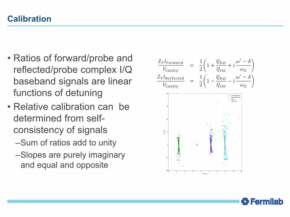
Calibration
• Ratios of forward/probe and reflected/probe complex I/Q baseband signals are linear functions of detuning
• Relative calibration can be determined from self-consistency of signals–Sum of ratios add to unity–Slopes are purely imaginary
and equal and opposite
= 12 1 + + −= 12 1 − − −
-6 -4 -2 0 2 4 6 8 10 12-20
-10
0
10
20
30
40
Re TP/F-1
Im T
P/F
-1
Forward/ProbeReflected/ProbeSumDifference
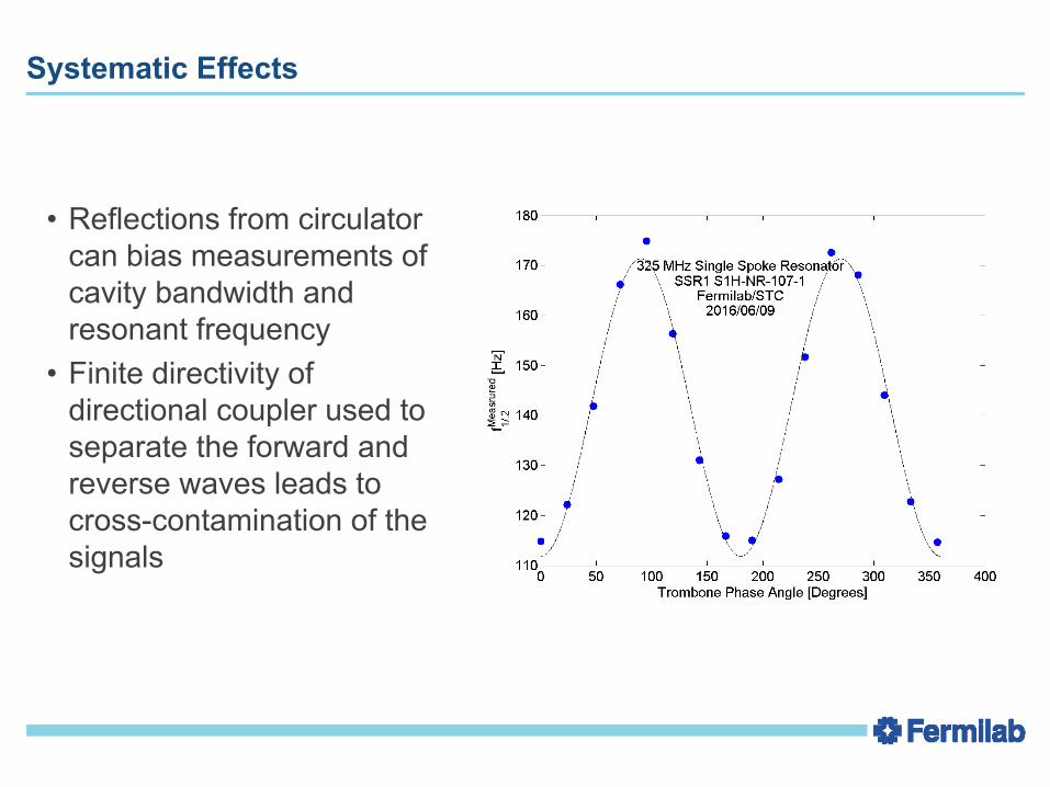
Systematic Effects
• Reflections from circulator can bias measurements of cavity bandwidth and resonant frequency
• Finite directivity of directional coupler used to separate the forward and reverse waves leads to cross-contamination of the signals
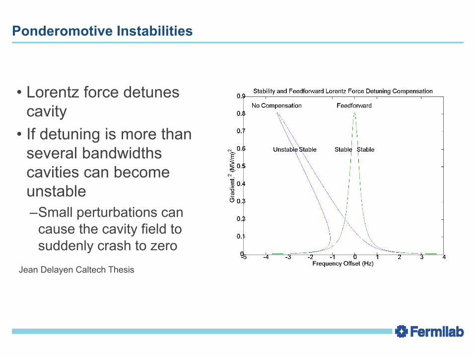
Ponderomotive Instabilities
• Lorentz force detunes cavity
• If detuning is more than several bandwidths cavities can become unstable–Small perturbations can
cause the cavity field to suddenly crash to zero
Jean Delayen Caltech Thesis
Stabilizing the Resonance
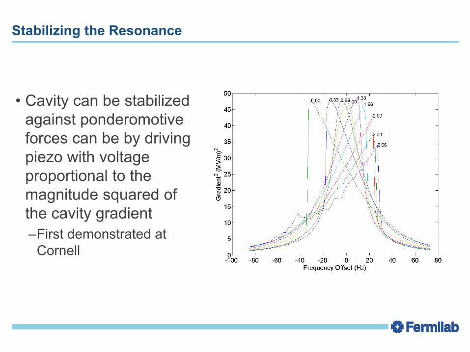
• Cavity can be stabilized against ponderomotive forces can be by driving piezo with voltage proportional to the magnitude squared of the cavity gradient–First demonstrated at
Cornell

Feedback
• Initial microphonicssuppression studies at Fermilab– http://lss.fnal.gov/archive/2003/conf/fermilab-
conf-03-315-e.pdf
• Extensive studies of microphonics at BESSY– Phys. Rev. ST Accel. Beams 13,
082001
Courtesy Axel Neumann
Adaptive Feedforward
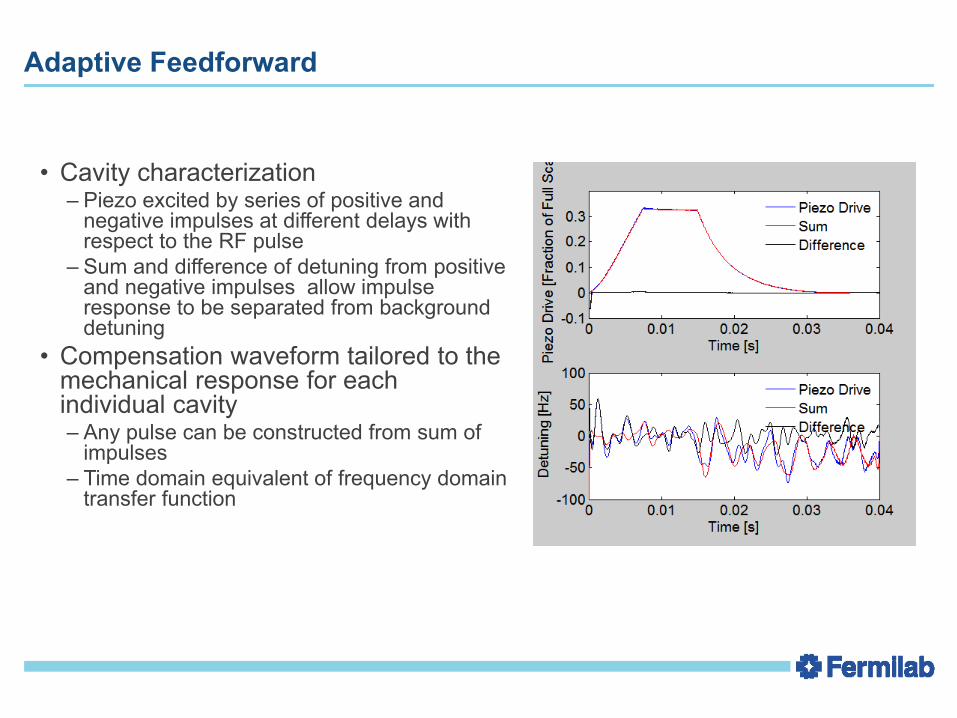
• Cavity characterization– Piezo excited by series of positive and
negative impulses at different delays with respect to the RF pulse
– Sum and difference of detuning from positive and negative impulses allow impulse response to be separated from background detuning
• Compensation waveform tailored to the mechanical response for each individual cavity– Any pulse can be constructed from sum of
impulses– Time domain equivalent of frequency domain
transfer function
(Inverse) Piezo/Detuning Transfer Function
• Piezo to Detuning transfer function can be inverted to determine the piezo waveform needed to cancel any detuning waveform
• Measure response to piezo pulses
δ=Τδ/PZTVPiezo
• Extract Transfer function from measured data
Τδ/PZT =δVTPiezo(Vpiezo VT
Piezo)-1
• Any deterministic detuning can be cancelled using the appropriate waveform
δ -Τδ/PZTVδ=0
Vδ= (ΤTδ/PZT Τδ/PZT)-1 (ΤT
δ/PZT δ)
• Numerical instabilities can be suppressed using SVD or Tikhionov Regularization
Adaptive Feedforward
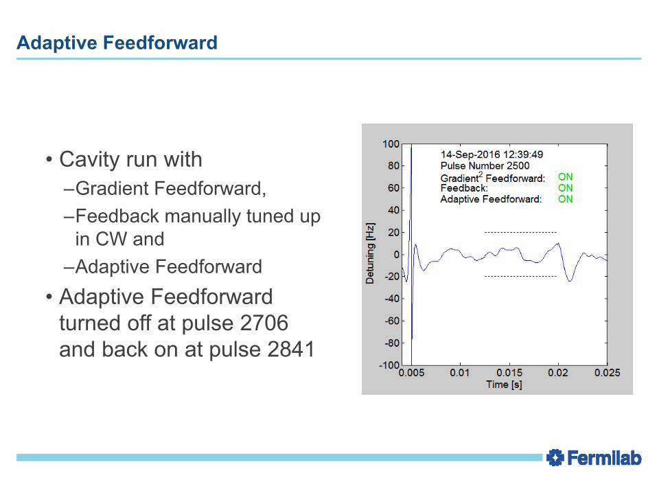
• Cavity run with –Gradient Feedforward, –Feedback manually tuned up
in CW and–Adaptive Feedforward
• Adaptive Feedforward turned off at pulse 2706 and back on at pulse 2841
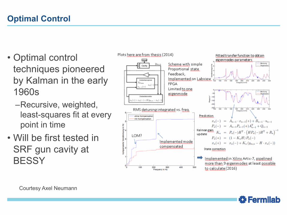
Optimal Control
• Optimal control techniques pioneered by Kalman in the early 1960s–Recursive, weighted,
least-squares fit at every point in time
• Will be first tested in SRF gun cavity at BESSY
Courtesy Axel Neumann
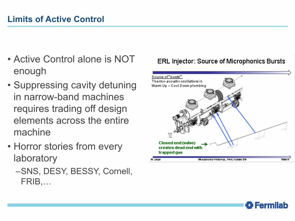
Limits of Active Control
• Active Control alone is NOT enough
• Suppressing cavity detuning in narrow-band machines requires trading off design elements across the entire machine
• Horror stories from every laboratory–SNS, DESY, BESSY, Cornell,
FRIB,…

Passive Control
• Passive control measures suppress vibrations before the can reach the cavity
• Ensuring adequate implementation of passive control measures requires– Outreach– Education, and – Enforcement
• Organizational challenges may be more daunting than the technical challenges
Conclusions
• Cavity detuning can be a major cost driver for narrow-band SRF accelerators
• Great strides have been made in active control– Ponderomotive effects can be suppressed using feed-forward proportional to the
gradient– Deterministic sources (e.g. LFD) can be suppressed using adaptive-feedforward– Non-deterministic sources (e.g. microphonics) can be suppressed using feedback
• Active control alone is not enough– Suppressing cavity detuning requires trading off design elemtns of the entire
machine– Organizational challenges may be more daunting than technical challenges
Recommended