touc
hS
OLU
TIO
NS
DEP
END
AB
LE ·
INN
OVA
TIVE
·G
LOB
AL ·E
XP
ERIE
NC
E D
EPEN
DA
BLE
·IN
NO
VATI
VE ·
GLO
BA
L ·E
XP
ERIE
NC
MicroTouchTM ResistiveIntegration Guide
3M Touch Systems Proprietary Information

Read and understand all safety informationbefore installing and using this product.

Copyright This manual is © 3M 2002. All rights reserved.
Reproduction of the contents of this copyrighted manual in whole or in part, by any means, electronic or mechanical, for any purpose, without written permission of 3M Touch Systems, a subsidiary of 3M, is prohibited.
Notice Given the variety of factors that can affect the use and performance of a 3M Touch Systems Product (the “Product”), including that solid state equipment has operation characteristics different from electromechanical equipment, some of which factors are uniquely within User’s knowledge and control, it is essential that User evaluate the 3M Touch Systems Product and software to determine whether it is suitable for User’s particular purpose and suitable for User’s method of application. 3M Touch Systems’ statements, engineering/technical information, and recommendations are provided for User’s convenience, but their accuracy or completeness is not warranted. 3M Touch Systems products and software are not specifically designed for use in medical devices as defined by United States federal law. 3M Touch Systems products and software should not be used in such applications without 3M Touch Systems’ express written consent. User should contact its sales representative if User’s opportunity involves a medical device application.
Important notice to purchaser
Specifications are subject to change without notice. These 3M Touch Systems’ Products and software are warranted to meet their published specifications from the date of shipment and for the period stated in the specification. 3M Touch Systems makes no additional warranties, express or implied, including but not limited to any implied warranties of merchantability or fitness for a particular purpose.
User is responsible for determining whether the 3M Touch Systems Products and software are fit for User’s particular purpose and suitable for its method of production, including intellectual property liability for User's application. If the Product, software or software media is proven not to have met 3M Touch Systems’ warranty, then 3M Touch Systems’ sole obligation and User’s and Purchaser’s exclusive remedy, will be, at 3M Touch Systems’ option, to repair or replace that Product quantity or software media or to refund its purchase price. 3M Touch Systems has no obligation under 3M Touch Systems’ warranty for any Product, software or software media that has been modified or damaged through misuse, accident, neglect, or subsequent manufacturing operations or assemblies by anyone other than 3M Touch Systems. 3M Touch Systems shall not be liable in any action against it in any way related to the Products or software for any loss or damages, whether non-specified direct, indirect, special, incidental or consequential (including downtime, loss of profits or goodwill) regardless of the legal theory asserted.
Edition August 2002Document Number: 19441 (Rev. 1.0) [Supersedes D-IG 100 and D-CDG 100]
Trademarks MicroTouch and TouchSurround are trademarks of 3M.
Clincher is a trademark of FCI. AMP is a trademark AMP Incorporated. Molex is a trademark of Molex Incorporated.
3M Touch Systems Proprietary Information


3M Touch Systems Proprietary Information
Contents
Preface Before you start .............................................................. 3About the manual ................................................................................... 3Your choices........................................................................................... 3About 3M Touch Systems...................................................................... 4
Chapter 1 Introducing resistive touch by3M Touch Systems ......................................................... 7Resistive touch ....................................................................................... 7Design types ........................................................................................... 8Standard and custom .............................................................................. 8Size ......................................................................................................... 8
Chapter 2 Construction.................................................................. 11Common features ................................................................................. 11FG construction .................................................................................... 11PL construction .................................................................................... 11Backing panels ..................................................................................... 11
Chapter 3 Tail and connector........................................................ 15Tail ....................................................................................................... 15Connector ............................................................................................. 16
Chapter 4 Surface finish and activation force ............................. 19Surface finishes .................................................................................... 19Activation force of the touch screen .................................................... 20
Chapter 5 Mounting........................................................................ 21Positioning the touch screen inside a bezel.......................................... 21Rear mounting or front mounting?....................................................... 22Rear mounting ...................................................................................... 22Front mounting..................................................................................... 26Designing to meet NEMA sealing standards ....................................... 27
Chapter 6 Graphics and switches................................................. 29Custom touch screen graphics.............................................................. 29Switches ............................................................................................... 31
Chapter 7 Gaskets.......................................................................... 33Options ................................................................................................. 33Comparing gaskets ............................................................................... 33Ordering gaskets................................................................................... 35
Chapter 8 Shields ........................................................................... 37About shields........................................................................................ 37Choosing............................................................................................... 37Grounding............................................................................................. 38
Appendix A Matrix touch screens.................................................... 43Appendix B Glossary ........................................................................ 45


3M Touch Systems Proprietary Information
PREFACEBefore you start
About the manualWho should read this guideThis manual is written for electrical and mechanical engineers, design engineers, and system integrators who are responsible for designing, positioning, installing, and/or maintaining MicroTouchTM resistive touch screen products.
How the guide is organizedThe manual provides guidelines for:
Selecting a standard resistive touch screen system for your application. If we do not have a standard touch screen to fit your needs, you can request a custom product quotation from your sales representative. To search our Sensor Selection Database, see www.3Mtouch.com.Requesting a custom product. A completed checklist is required by 3M Touch Systems so we can efficiently quote on the touch solution that is right for your application. Your sales representative will work with you to complete the Quotation Checklist (see “Contacting your regional touch specialist” on page 4).Integrating your touch screen into your application. Detailed information is included to equip the integrator with the information necessary to integrate the touch screen as smoothly as possible. The single most important chapter for integrators is Chapter 5.
Your choicesThere are many choices available to you when designing and integrating your resistive touch screen system. There are basic choices that need to be made, whatever your application, and there are also options that may make for an even better fit between the touch screen and your application.
The basicsThe basic decisions you need to make regarding the touch screen include:
Type of screen: 4-wire, 5-wire, or 8-wire.Size: Size of screen, overall thickness required for application.Construction type: PL (Polyester Laminated) or FG (Film-on-Glass), including choices about backing panel material.

4 Resistive Touch Screens Design & Integration Guide
3M Touch Systems Proprietary Information
Tail: Location and length.Connector: Type and size.Mounting technique: Front-mounting or rear-mounting.Surface finish: Antiglare, for example.Activation force of touch screen: Responds to finger/pen, for example.Controlling electronics: 3M Touch Systems offers a variety of controllers to accompany our 4-, 5-, and 8-wire touch screen configurations. For details, contact your 3M Touch Systems sales representative.
The OptionsThere are several options available to further customize your resistive touch screen system for your application.
Graphics. An optional graphic layer can be added to both PL and FG constructions. The graphic layer can incorporate software switches, referred to as TouchSurroundTM, which may be placed outside the touch screen’s clear window.Switches. There are options for discrete switches. They use their own traces and operate independently of the rest of the touch screen).Gaskets. There are options for gaskets made of various materials, thicknesses, and adhesion levels for applications running in an environment that requires the touch screen to be sealed or to be able to withstand shock and/or vibration.Shields. Various optional shield configurations are available if your application is running in an environment where there is significant electromagnetic interference.
About 3M Touch SystemsContacting your regional touch specialistTo find the name of your 3M Touch Systems sales representative, refer to the www.3Mtouch.com.
Work with your regional sales representative to complete the quotation checklist.
3M Touch Systems Support Services3M Touch Systems provides extensive support services through our website and technical support organization. Visit the 3M Touch Systems website at www.3Mtouch.com , where you can download touch screen software and drivers, obtain regularly updated technical documentation on 3M Touch Systems products, and learn more about our company.
Whenever you contact Technical Support, please provide the following information:
Part number and serial numberCurrent driver versionOperating system usedInformation on peripherals

3M Touch Systems Proprietary Information
Before you start 5
Technical Support is available Monday through Friday 8 a.m. to 8 p.m. US Eastern Standard Time – 9 a.m. to 5 p.m. throughout Europe. Limited call back service Saturdays and Sundays.
You can contact 3M Touch Systems Technical Support (US only -- Eastern Standard Time) by calling the hot line or sending a fax.
Technical Support Hot Line: 978-659-9200Technical Support Fax: 978-659-9400Toll Free: 1-866-407-6666Email: [email protected]
3M Touch Systems Worldwide OfficesAll offices can be reached through the website: www.3Mtouch.com.
Country Telephone number
United States 978-659-9000
Australia 61-395-82 4799
Canada 604-521-3962
France +33 (1) 45 13 90 30
Germany +49 (0) 211-59907-0
Hong Kong/China (852) 2333-6138
Italy +39 (0) 39-230-2230
Japan +81 (44) 811-1133
Korea +822 552 3198
Singapore +65-96279173
Spain +34 934 15 6285
Taiwan +886-2-2704-9011
United Kingdom +44 (0) 1235-444400


3M Touch Systems Proprietary Information
CHAPTER 1Introducing resistive touch by3M Touch Systems
About the chapterThis chapter describes:
How resistive touch screens workMain types of resistive touch screens available from 3M Touch SystemsSize options available for our resistive touch screens
Resistive touchResistive technology is versatile and economical for applications such as food service and retail point-of-sale, industrial process control and instrumentation, portable and handheld products, and communication devices.
Figure 1: Resistive touch screen technology
Resistive touch screens have a flexible top layer and a rigid bottom layer separated by insulating spacer dots, with the inside surface of each layer coated with a transparent conductive coating. Voltage applied to the layers produces a gradient

8 Resistive Touch Screens Design & Integration Guide
3M Touch Systems Proprietary Information
across each layer. Pressing the flexible top sheet creates electrical contact between the resistive layers, essentially closing a switch in the circuit. Depending on the controller electronics you use, they either alternate voltage gradient horizontally and vertically to get x then y touch coordinates or they simultaneously measure the current at each corner (Figure 1).
Design types3M Touch Systems offers a wide range of resistive touch screen designs to fit a range of application requirements. We offer three types of resistive products in two different constructions:
5-wire, offered in FG (Film-on-Glass). FG construction consists of a flexible layer of film on a glass backing panel.8-wire, offered in FG and PL (Polyester Laminated). PL construction consists of two polyester layers. One layer remains flexible while the other is typically bonded to a chemically strengthened glass backing panel.4-wire, offered in FG and PL.
The design and type of touch screen construction you choose will depend upon how and where your touch product will be used. Table A is a guide to help you select the type of touch screen you will need for your project. For more information on construction types, see Chapter 2.
Standard and custom3M Touch Systems has an extensive selection of standard touch screen sizes to fit most flat panel and curved displays. These are available quickly without costly art and design charges and are ideal for samples, prototyping, and pre-production.
For current size options, visit the Sensor Selection Database on our Web site at www.3Mtouch.com. If you cannot find the touch screen size and construction that you need, contact your sales representative.
SizeWhen deciding on the overall dimensions of your touch screen, consider the following:
Table A: Range of resistive products available from 3M Touch Systems
4-wire/8-wire FG 4-wire/8-wire PL 5-wire FG
Range of applications
Portable devicesConsumer devicesWeb padsThin clientsRemote controls
Rugged portablesIndustrial controlsInstrumentationHarsh environments
Point-of-saleRetailHospitalityVoting machinesFinancial
Product features
Film on glassLower power consumptionSmaller sizes1-year warranty
Polyester laminatedChemically strengthened glassImpact strength3-year warranty
Film on glassPhysically robustEnvironmentally robust5-year warranty

Introducing resistive touch by 3M Touch Systems 9
3M Touch Systems Proprietary Information
Location of mounting holes. To mount the touch screen most simply, the display’s mounting holes should be outside the perimeter of the touch screen. If this is not an option, you can consider mounting the touch screen with a mounting plate (see Figure 10 on page 25).Active area. The active area of the touch screen should match the active area of the display (Figure 2).Viewing area. The viewing area of the touch screen is typically designed to match the viewing area of the display (Figure 2).Size of bezel opening. 3M Touch Systems recommends that the bezel be placed between the viewing area and active area. For details, see Table H on page 23.
Figure 2: Active area and viewing area
Registration tolerance. 3M Touch Systems uses the backing panel of the touch screen for registration of the other layers. The backing panel is cut to an overall size tolerance (length and width) of ± 0.015 inches (0.4 mm). Keep this in mind when designing your assembly.


3M Touch Systems Proprietary Information
CHAPTER 2
Construction
About the chapterThis chapter describes:
Features common to all of our resistive constructionsConstruction choices: PL and FGBacking panel choices
Common features Resistive touch screens from 3M Touch Systems are either Polyester Laminated (PL) or Film-on-Glass (FG) constructions. All constructions are:
Scratch-resistantChemical-resistantCapable of being sealed (NEMA, IP)Provide reliable and accurate touch input, even when users are wearing gloves. Come with Anti-Newton Ring (ANR) technology which eliminates undesirable interference patterns that occur when two or more clear surfaces are close together.
FG constructionFG construction consists of a flexible layer of film on a conductive coated glass backing panel. FG construction offers greater transmissivity than PL touch screens, but less impact resistance.
PL constructionPL construction consists of two polyester layers. One layer remains flexible while the other is typically bonded to a non-conductive, chemically strengthened glass backing panel..
Backing panelsAll resistive touch screens from 3M Touch Systems have a backing panel that provides strength and durability.
For custom products, you can select the material and thickness of the backing panel.

12 Resistive Touch Screens Design & Integration Guide
3M Touch Systems Proprietary Information
MaterialFor PL touch screens, backing panels are available in glass, acrylic, and polycarbonate. For FG constructions, the backing panel material is always glass.
GlassA glass backing panel is a good choice if flatness is required and if the touch screen will be located where there are temperature and humidity fluctuations.
A glass backing panel is cut to an overall size tolerance of ± 0.015 inches (0.4 mm).
AcrylicAcrylic backing panels are typically chosen for custom applications that need a lighter, more shatter-resistant product (for example, in food industries and educational environments).
Polycarbonate3M Touch Systems offers 0.020" (0.5 mm) polycarbonate backing panels for custom applications that require a light, thin, break-resistant touch screen. A hardcoated, scratch-resistant surface is applied to the rear of the polycarbonate backing panel to protect it during manufacturing and handling.
ThicknessThe choice of backing panel thicknesses should be based on:
Material of the backing panelSize of the touch screenCoefficient of thermal expansion (CTE) of the backing panel
The co-efficient of thermal expansion (CTE) for backing panel materials (Table C) is vital in choosing the backing panel. The CTE measures the rate at which the material of a backing panel expands and contracts.
The closer the CTE of the materials are to one another, the less prone the touch screen will be to distortion (e.g., bagging, pillowing, warping, stretching) from environmental changes over time.
Table B:
Figure 3: FG construction Figure 4: PL construction

3M Touch Systems Proprietary Information
Construction 13
Recommended backing panel thicknesses for panels constructed of different materials and having different touch screen sizes are shown in Table D (acrylic) and Table E (glass).
Table C: CTE for backing panel materials
Backing panel material Coefficient of thermal expansion (CTE)*
Glass 5 × 10⁻⁶ inches/inches ºF
Acrylic 34 × 10-6 inches/inches ºF
Polycarbonate 39 × 10-6 inches/inches ºF
Polyester 17 × 10-6 inches/inches ºF
*Typical CTE for backing panel materials tested by 3M Touch Systems.
ImportantIt is important to follow the recommendations of 3M Touch Systems for backing panel thickness. It is also important to follow recommended operating and storage conditions related to humidity as stated in teh Resistive Touch Screen Specifications. Doing so will help ensure that touch screen layers expand and contract at the same rate as the backing panel and so prevent bagging, pillowing, and stretching. For a copy of the Resistive Touch Scree Specifications, contact your sales representative.
Table D: Recommended backing panel thicknesses: Acrylic
Use this backing panel thickness For this size of touch screen
0.060" (1.5 mm) 5" and smaller
0.080" (2 mm) 7" and smaller
0.100" (2.5 mm) 9" and smaller
0.125" (3.2 mm) 11" and smaller
0.187" (4.8 mm) 14" and smaller

14 Resistive Touch Screens Design & Integration Guide
3M Touch Systems Proprietary Information
Table E: Reco mmended backing panel thicknesses: Glass
Use this backing panel thickness For this size of touch screen
PL construction
0.028" (0.7 mm) 3" and smaller
0.043" (1.1 mm) 6" and smaller
0.062" (1.6 mm) 12" and smaller
0.079" (2.0 mm) 13" and smaller
0.093" (2.4 mm) 14" and smaller
0.125" (3.2 mm) 16" and smaller
FG construction
0.043" (1.1 mm) 6" and smaller
0.062" (1.6 mm) 10" and smaller
0.075" (1.9 mm) 14" and smaller
0.114" (2.9 mm) Larger than 14"

3M Touch Systems Proprietary Information
CHAPTER 3Tail and connector
About the chapterThis chapter provides guidelines for choosing tails and connectors for your custom application and indicates some of the features and constraints of each. You can specify:
Location of the tailLength of the tailType of connectorSpecial pin-outs (if required)
TailLocationThe location of the touch screen tail must be specified. It is recommended that the tail be located:
On a shorter edge of the touch screen, if possible (Figure 5).So that it is not routed past unshielded, high-voltage sources (e.g., backlights).For 5-wire touch screens, center the tail if possible. If centering is not possible, place the tail a minimum of 1" (25 mm) from a corner.
Figure 5: Location of the touch screen tail
16 Resistive Touch Screens Design & Integration Guide
3M Touch Systems Proprietary Information
LengthIt is recommended that the tail length be:
Between 2 to 3 inches (50 to 75 mm), with the combined length of the tail and touch screen not exceeding 20 inches (508 mm).When using an FCI (Berg) connector, minimum 1 inch (25.4 mm).When using an AMP connector, minimum 2 inches (50.8 mm).
Typically, long tails are more expensive than short tails.
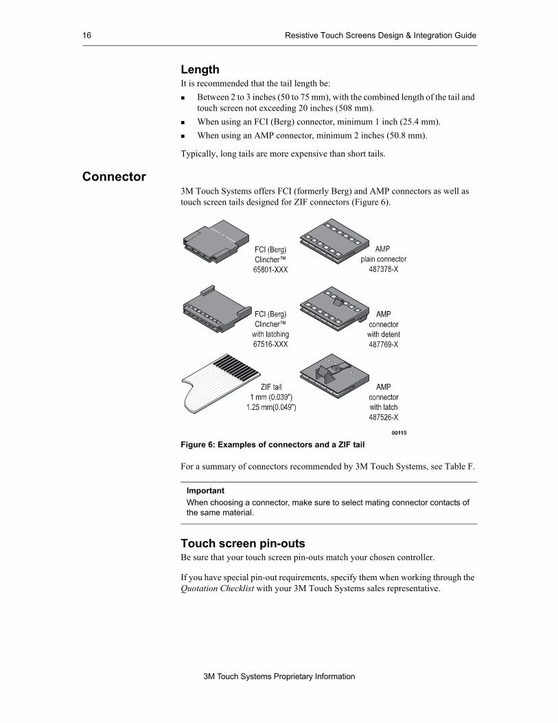
Connector3M Touch Systems offers FCI (formerly Berg) and AMP connectors as well as touch screen tails designed for ZIF connectors (Figure 6).
Figure 6: Examples of connectors and a ZIF tail
For a summary of connectors recommended by 3M Touch Systems, see Table F.
Touch screen pin-outsBe sure that your touch screen pin-outs match your chosen controller.
If you have special pin-out requirements, specify them when working through the Quotation Checklist with your 3M Touch Systems sales representative.
ImportantWhen choosing a connector, make sure to select mating connector contacts of the same material.

Tail and connector 17
3M Touch Systems Proprietary Information
Table F: Summary of connectors recommended by 3M Touch Systems
Connector type and size Constraints Features More information
FCI (formerly Berg)
ClincherTM Latching Receptacle 0.100" (2.5 mm)Clincher Receptacle 0.100" (2.5 mm)
Tail length must be minimum 1" (25.4 mm)
Easy to extend tail lengthEasy to connect to the MicroTouchTM SC4 controllerTin or gold contacts available
www.fciconnect.com
AMPTM
Three housing options (all for four-pin and eight-pin connectors) 0.100" (2.5 mm).
PlainLatchDetent
Tail length must be minimum 2" (50.8 mm)Must specify appropriate housing and receptacle
Locking feature available so that connector doesn’t work loose; makes AMP the best choice for shock-prone and vibration-prone environments.Easy to connect to the MicroTouch MT410 or MT510.Easy to extend tail with additional cabling.Three housing options (see "Connector type" column).
www.tycoelectronics.com
ZIF3M Touch Systems offers two pitch tails that are designed for ZIF connectors:
1 mm (0.039") pitch tail. Recommended connectors:For 4-wire, 5-wire, and 8-wire:
Molex 52043, 52089, 52207, 71220, 71226AMP 487951, 487952
For 8-wire only:Molex 52030, 52271, 52610
1.25 mm (0.049") pitch tailMolex 5597
When using ZIF connector with touch screens, tail traces must face down.Must specify a connector that is compatible with a tail design of carbon/silver ink.Difficult to extend tail.More difficult to connect to a MicroTouch controller.Not available for 5-wire resistive.
Minimum tail length not a major concern.Suited to small designs with a small connector and a narrow tail.Surface mount connectors are available.
www.avxcorp.com


3M Touch Systems Proprietary Information
CHAPTER 4Surface finish and activation force
About this chapterThis chapter discusses two types of custom resistive choices:
Surface finish (for abrasion protection and enhanced viewing quality)Activation force
Surface finishesAbrasion protectionAll resistive touch screens from 3M Touch Systems include a proprietary hardcoated polyester on the front surface of the screen that is substantially harder and more abrasion-resistant than uncoated touch screens.
Viewing qualityHigh-gloss and anti-glare finishes can be applied to the touch screen surface. Consider the optical values of each type of finish when choosing whether one of these would be appropriate for your application (Table G).
AntiglareAntiglare finishes reduce glare, are scratch resistant, do not show fingerprints easily, and provide a smoother feel for drag-and-drop and stylus applications. Two antiglare finishes are available for our resistive touch screens:
Anti-glare finish HCG12 offers high clarity and is well suited for indoor applications. Anti-glare finish HCG10 provides superior antiglare qualities and is often used in outdoor settings.

20 Resistive Touch Screens Design & Integration Guide
3M Touch Systems Proprietary Information
High-glossThe high-gloss finish, HCC01, delivers superior image quality. This finish is reflective, however, so it may not be suitable for a touch screen that will be used outdoors or in a setting with high ambient light.
Activation force of the touch screenThe activation force of a touch screen affects its touch sensitivity.
The standard activation force of our resistive touch screens is optimized for finger and stylus use. However, 3M Touch Systems can manufacture a touch screen with customized activation force, such as palm rejection.
If you think your application may require customized activation force, contact 3M Touch Systems technical support.
Table G: Optical characteristics of assembled touch screen (does not apply to buffer designs)
Touch screen type
Front surface hardcoat
Haze*
(values are typical)Clarity*
(values are typical)
FG HCC01 2% 90%
HCG12 5% 80%
HCG10 11% 64%
PL HCC01 3% 93%
HCG12 5% 77%
HCG10 13% 65%
*Values derived using BYK Gardner hazegard plus

3M Touch Systems Proprietary Information
CHAPTER 5Mounting
About the chapterThis chapter provides guidelines to help you to make the best mounting choices for your application as you discuss mounting options with your sales representative and as you integrate the touch screen with your application.
Specifically, the chapter includes guidelines on:Rear mounting, including:
Special guidelines for rear mounting PL and FG touch screens.Steps for rear mounting directly.Steps for rear mounting using a mounting plate.
Front mounting.Positioning the touch screen inside a bezel.Mounting to achieve NEMA sealing standards.
Positioning the touch screen inside a bezelGuidelines
As a general rule, your product’s bezel should be 0.030 inches to 0.060 inches (0.8 mm to 1.5 mm) away from the touch screen’s active area and 0.030 inches to 0.060 inches (0.8 mm to 1.5 mm) inside the screen’s viewing area.For touch screens less than 12 inches (300 mm), the layer-to-layer assembly tolerance of the screen is 0.030 inches (0.8 mm). For touch screens 12 inches (300 mm) and larger, the layer-to-layer assembly tolerance of the screen is 0.050 inches (1.3 mm).When mounting the touch screen in environments where there are temperature and humidity fluctuations, 3M Touch Systems recommends that a glass backing panel be used because it expands and contracts at approximately the same rate as the rest of the touch screen. If you cannot use a glass backing panel for some reason, consider the coefficient of thermal expansion (CTE) of your backing panel material. For more information on the CTE for different backing panel materials, refer to Chapter 2.

22 Resistive Touch Screens Design & Integration Guide
3M Touch Systems Proprietary Information
If you’re going to be mounting the touch screen in an environment with a high sulfur concentration, contact 3M Touch Systems technical support.
Rear mounting or front mounting?Our resistive touch screens can be mounted from the rear or the front. Rear mounting is the most convenient method for most applications.
Front mounting works well if you need a uniformly smooth surface on the front of your product. Front mounting requires that the bezel be specially designed to accommodate a resistive touch screen produced by 3M Touch Systems.
Rear mountingGuidelinesTo rear mount a touch screen is to position it behind the bezel. Rear mounting can be done using the display or a mounting plate.
Before rear mounting your touch screen, consider the following guidelines to help ensure optimal performance. Unless otherwise noted, these guidelines apply to all resistive constructions.
Mounting environmentMount the touch screen in a clean environment so that dust is not trapped between the touch screen and the display.
AligningAlign the touch screen and display so that the active area of the touch screen is centered on the active area of the display.
Mounting holesTo mount the touch screen in the simplest way, make sure that the display’s mounting holes are outside the perimeter of the touch screen. If this is not an option and the touch screen covers the display’s mounting holes, then use a mounting plate (see “Mounting with a mounting plate” on page 25).
Avoid bonding touch screen to the back of the bezelMount the touch screen so that it is supported from the rear instead of using an adhesive that bonds the touch screen to the back of your bezel.
ImportantHigh sulfur concentrations can cause a reaction with the exposed silver in the tail, causing tarnish or failures. To prevent this, 3M Touch Systems can recommend a custom tail configuration.
ImportantAttaching the touch screen to the bezel makes the polyester adhere to the bezel and prevents the polyester from expanding and contracting in response to fluctuations in temperature and humidity. This can damage the polyester by making it bag, stretch, pillow, or otherwise be distorted.

Mounting 23
3M Touch Systems Proprietary Information
Assembly toleranceFor touch screens with outer dimensions less than 12 inches (300 mm), the layer-to-layer assembly tolerance of the screen is 0.030 inches (0.8 mm). For touch screens with outer dimensions that are 12 inches (300 mm) or larger, the layer-to-layer assembly tolerance of the screen is 0.050 inches (1.3 mm). These tolerances are factored into the dimensions shown in Table H.
Bezel clearancesThe bezel clearances recommended in Table H are intended to prevent accidental activation of or damage to the touch screen when clamping force is applied. The recommended clearances depend on two factors:
Whether or not the touch screen has a buffer layer. The mechanical drawing will indicate if there is a buffer layer.Size of the touch screen..
Table H: Recommended bezel clearances
Touch screen type Clearance areas2,3
Small screens4
Large screens5
Non-buffer-layer1 ABetween edge of viewing area and bezel.
0.03"0.8 mm
0.05"1.3 mm
Buffer layer1 BBetween edge of spacer and bezel. (for non-buffer layer touch screen).
0.09"1.3 mm
0.11"2.8 mm
CBetween edge of active area and bezel.
0.03"0.08 mm
0.05"1.3 mm
DBetween edge of spacer and bezel (for buffer layer touch screen).
0.03"0.8 mm
0.05"1.3 mm
1The mechanical drawing of the part will indicate whether it includes a buffer layer.2For non-buffer layer touch screens, two edges have the same dimensions for the spacer opening and the viewing area and two edges have different dimensions. Different bezel clearances apply as shown above. The mechanical drawing will indicate to which edges each dimension applies.3For buffer layer touch screens, the dimensions of the spacer opening and the viewing area are the same on all edges.4Small screens outer dimensions: less than 12 inches5Large screens outer dimensions: 12 inches or larger

24 Resistive Touch Screens Design & Integration Guide
3M Touch Systems Proprietary Information
Rear mounting guidelines exclusively for non-buffer-layer constructionsBacking panel and registrationMount the touch screen so that the backing panel is used for registration within the bezel. The backing panel is cut to an overall size (length and width) tolerance of ±0.015 inches (0.4 mm).
Smooth bezel undersideUse a gasket in combination with a bezel that has a continuous boss, ridge, or groove so that the underside of the bezel is smooth and does not contact the touch screen surface inside the spacer opening.
Figure 7: Achieving smooth bezel underside
Tail positionIn noisy environments, 3M Touch Systems recommends that you avoid routing the touch screen past unshielded, high-voltage sources (such as backlights).
Position the touch screen tail so that its bend radius is greater than 0.125 inches (3.3 mm). The tail can be damaged and the product warranty voided if the tail is severely creased. Also avoid having multiple bends in the tail.
Figure 8: Recommended (and not recommended) bend radius for tail
Hiding the circuitryEnhance the appearance of the touch screen and your application.
Mounting directlyThe easiest and most affordable way to rear mount the touch screen is by screwing the display to the rear of your product’s bezel. Here are the steps:

Mounting 25
3M Touch Systems Proprietary Information
1. Align and adhere the touch screen to the display, using a gasket (Figure 9). For information about gasket options, see Chapter 7.
2. Secure the display to the bezel using the display’s mounting holes.
Figure 9: Example of rear mounting a touch screen directly
Mounting with a mounting plateThe other way to rear mount the touch screen is by using a mounting plate. This method is recommended if:
Your touch screen covers the display’s mounting holes.You need a versatile mounting method that will allow several holes to be made to accommodate various displays.You need good shock absorption.
Figure 10: Example of rear mounting a touch screen with a mounting plate

26 Resistive Touch Screens Design & Integration Guide
3M Touch Systems Proprietary Information
Here are the steps for rear mounting with a mounting plate:1. Attach the display to the mounting plate.
2. Align and adhere the touch screen to the display by using mounting adhesive (see Figure 10).
3. Secure the assembly to your product’s bezel.
Front mountingGuidelinesWhen deciding whether front mounting is appropriate for your application, there are some constraints that you need to bear in mind.
If you choose to design for front mounting:The touch screen will need to be integrated into a bezel specifically designed to accommodate it.If a graphic layer is used, it should be optically bonded to the entire touch screen surface. Using a graphic with a cutout window will cause problems.The gap between the touch screen and display will be larger than it would be with the rear mounting method.There will be a height difference between the bezel and the touch screen, so that void will need to be filled. Options include:
Designing an embossed edge around the entire perimeter, as in Figure 12 (recommended by 3M Touch Systems), or
Heat staking the plastic bezel to the touch screen.
The touch screen will need to be supported from the back so that it can withstand recurrent touches. One option for achieving this is to place adhesive on the back of the touch screen and attach it to the bezel.If an overhanging graphic area is too large, it can be damaged during handling and shipping.The touch screen tail must be designed to fold back gently. If the tail is sharply bent, it will create a bulge in the graphic layer.In most cases, the active area of the touch screen should match the active area of the display.Include an overhanging graphic area with a rear mounting adhesive (Figure 11).
Figure 11: Cross section of front mounting method

Mounting 27
3M Touch Systems Proprietary Information
Include ledges on the bezel to hold the overhanging graphic and the touch screen backing panel. Make sure the ledges are strong enough to withstand recurrent touches.Position the touch screen tail so that its bend radius does not cause delamination of the touch screen area.
Figure 12: Embossed edge around the bezel
Designing to meet NEMA sealing standardsWith the touch screen properly mounted, your product can be sealable to NEMA 12, NEMA 4, and NEMA 4X.
NEMA 12. For indoor applications, NEMA 12 enclosures provide a degree of protection against dust, falling dirt, and dripping non-corrosive liquids. NEMA 12 enclosures are not intended to provide protection against internal condensation.NEMA 4. For indoor and outdoor applications, NEMA 4 enclosures provide a degree of protection against wind-blown dust and rain, splashing water, and water directed by a hose. NEMA 4 enclosures are undamaged by the formation of ice on them, but NEMA 4 enclosures are not intended to provide protection against conditions such as internal condensation or internal icing.NEMA 4X. NEMA 4X enclosures provide the same level of protection for indoor and outdoor applications as the NEMA 4 standard plus protection against corrosion.
ImportantWhen your product meets one of the specified NEMA standards, it also meets the IP standard (a European designation). However, if your product meets a specified IP standard, it does not necessarily meet a NEMA standard.

28 Resistive Touch Screens Design & Integration Guide
3M Touch Systems Proprietary Information
When using resistive touch screens to meet a certain standard, consider such factors as your product’s working environment, temperature and humidity, type of bezel, and method of mounting. For more information about standards, please contact 3M Touch Systems technical support.
Table I: IP standards for NEMA 4, NEMA 4X, and NEMA 12 standards
NEMA standard IP standard
4 and 4X IP56
12 IP52
Source: NEMA Standards Publication 250-1997. Enclosures for Electrical Equipment (1000 Volts Maximum). National Electrical Manufacturers Association. 1998.

3M Touch Systems Proprietary Information
CHAPTER 6Graphics and switches
About this chapterThis chapter provides information on custom resistive options for:
A graphic layerDiscrete and software switches
Custom touch screen graphicsYou can enhance the user interface by creating a border with touch-sensitive graphics (e.g., touchable buttons, icons, pictures, logos) around the display.
You can do this by using a touch screen that is larger than the display and adding an optional graphic layer to the top circuit layer of FG and PL touch screens (Figure 13 and Figure 14). The graphic layer is affixed with optical adhesive.
3M Touch Systems accepts film or electronic files to produce custom graphics that can be incorporated into many of our custom resistive touch screens.
Figure 13: FG construction (with graphic layer)
00066C
Graphic layer
Top circuit layer
Spacer adhesive
Glass bottom circuit layerwith ITO conductive coating
Clear or antiglare scratchresistant finish

30 Resistive Touch Screens Design & Integration Guide
3M Touch Systems Proprietary Information
Figure 14: PL construction (with graphic layer)
GuidelinesWhen choosing graphic features for your custom resistive touch screen system, bear these points in mind:
Only one color may be used around the inner edge of the touch screen’s clear window. Secondary colors should be 0.075 inches (1.9 mm) from the edge of the clear window.With each color added to a graphic, the cost increases.
Figure 15: Example of a touch screen with graphics
00109_C
Top circuit layer
Spacer adhesive
Bottom circuit layer
Backing panel
Graphic layer
Clear or antiglare scratchresistant finish

Graphics and switches 31
3M Touch Systems Proprietary Information
SwitchesDiscrete switches or software (programmable) switches can be included in your custom resistive touch screen. You can also customize the sensitivity of your screen.
DiscreteDiscrete switches are buttons that use their own traces. In other words, the switches work independently of the rest of the touch screen. That may be a useful option when the switch is used for power or for another safety-related function. Discrete switches can be used with analog resistive or matrix touch screens. (For information on matrix touch screens, see Appendix A, starting on page 43.)
Software switchesSoftware switches are buttons that are outside the touch screen’s clear window and use 3M Touch Systems software to detect touches. Software switches suit applications where the function or location of a button may change at a later date
Figure 16: Example of a software switch
Table J: Advantages and disadvantages of discrete switches
Advantages Disadvantages
Use their own traces, ensuring that the switches work independently of the touch screen.
Reduce flexibility because the switch cannot easily be moved.
Do not require re-calibration. Add cost to the design of the touch screen.
Increase the number of pins on the touch screen tail connector.

32 Resistive Touch Screens Design & Integration Guide
3M Touch Systems Proprietary Information
EmbossingThe most cost-effective way to add switches is with a flat, non-embossed icon. However, if you need embossing, 3M Touch Systems can provide two types: rim embossed and pillow embossed switches.
A rim embossed switch is one that is raised just around the button’s perimeter (Figure 17). It is available as either a discrete switch or a software switch.
Figure 17: Rim embossed switch
A pillow embossed switch has a raised button that emits a click when pressed. Tactile switches are available only as discrete switches. All tactile switches use pillow embossing (Figure 18).
Figure 18: Pillow embossed switch
Table K: Advantages and disadvantages of the software switches
Advantages Disadvantages
Provide flexibility because the switch can be moved and functionality can change.
Extra time to configure the switches (using the software) may be necessary.
Require no additional pins on the touch screen tail connector.

3M Touch Systems Proprietary Information
CHAPTER 7Gaskets
About this chapterGaskets are available for resistive touch screens to keep dust and moisture out, reduce the effects of shock and vibration, and seal the touch screen to a flat panel display.
This chapter presents:Gasket options available and a comparison of when different gasket types are most suitable.How to order gaskets from 3M Touch Systems.
OptionsYou have a number of options when choosing a gasket. You may choose a gasket:
For different sides of the touch screen, specifically: Rear Front On both sides
With foamWith double-sided (rear only) or single-sided (front side) adhesive
Comparing gasketsYour application will dictate the most appropriate gasket(s) to use with your resistive touch screen. The advantages of various gasket types are described below. For a complete specification list of gaskets available for resistive touch screens from 3M Touch Systems, see Table L.
Rear gasketChoose a rear gasket to secure the touch screen to the display, keep dust away from the display, and minimize the impact of shock and vibration.
34 Resistive Touch Screens Design & Integration Guide
3M Touch Systems Proprietary Information
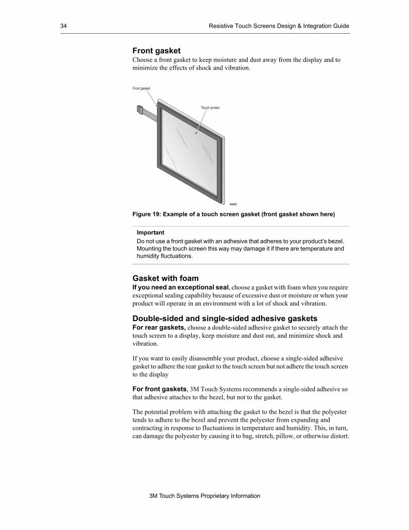
Front gasketChoose a front gasket to keep moisture and dust away from the display and to minimize the effects of shock and vibration.
Figure 19: Example of a touch screen gasket (front gasket shown here)
Gasket with foam If you need an exceptional seal, choose a gasket with foam when you require exceptional sealing capability because of excessive dust or moisture or when your product will operate in an environment with a lot of shock and vibration.
Double-sided and single-sided adhesive gasketsFor rear gaskets, choose a double-sided adhesive gasket to securely attach the touch screen to a display, keep moisture and dust out, and minimize shock and vibration.
If you want to easily disassemble your product, choose a single-sided adhesive gasket to adhere the rear gasket to the touch screen but not adhere the touch screen to the display
For front gaskets, 3M Touch Systems recommends a single-sided adhesive so that adhesive attaches to the bezel, but not to the gasket.
The potential problem with attaching the gasket to the bezel is that the polyester tends to adhere to the bezel and prevent the polyester from expanding and contracting in response to fluctuations in temperature and humidity. This, in turn, can damage the polyester by causing it to bag, stretch, pillow, or otherwise distort.
ImportantDo not use a front gasket with an adhesive that adheres to your product’s bezel. Mounting the touch screen this way may damage it if there are temperature and humidity fluctuations.

Gaskets 35
3M Touch Systems Proprietary Information
Ordering gasketsAdd a gasket to your touch screenGaskets can be added to a custom designed resistive touch screen by request or by working with your sales representative to complete the Resistive Quotation Checklist. Gaskets may also be added to standard 4-, 5-, and 8-wire resistive touch screens.
Table L: Recommend gasket materials
Gasket number
Base material
Type Adhesion level
Thickness Cost Example of application
Double-sided adhesive gaskets
01 Supported adhesive
Rear Medium — ideal for most applications
0.003”(0.08 mm)
Low Secure touch screen to display
02 Supported adhesive
Rear Medium 0.008” (0.2 mm)
Low Secure touch screen to display
03 3M 9871 Rear Low 0.0025”(0.06 mm)
Moderate Secure touch screen to displayAllows disassembly
04 3M 9495MP Rear Very high 0.005”(0.13 mm)
High Strongly secure touch screen to display
Double-sided adhesive gaskets with foam
05 Foam 6 with adhesive 3
Rear Low 0.035” (0.89 mm)
Moderate Secure touch screen to displayAllows disassembly
Single-sided adhesive gaskets with foam
06 Black closed cell polyethylene
Front or rear
Medium 0.031” (0.79 mm)
Low Seal touch screen to bezelAllows disassembly
07 Black closed cell polyethylene
Front or rear
Medium 0.064” 1.63 mm)
Moderate Seal touch screen to bezelAllows disassembly
08 Black closed cell polyethylene
Front or rear
Medium 0.033” (0.84 mm)
High Seal touch screen to bezelAllows disassembly

36 Resistive Touch Screens Design & Integration Guide
3M Touch Systems Proprietary Information
The following conditions apply to adding a gasket to a standard product:Gaskets are not sold separately.3M Touch Systems will mount recommended gaskets to our sensors with a 50-piece minimum order quantity.Due to the high number of possible gasket and size combinations, please contact your sales representative for a quotation and part number.Applying a gasket could add up to 3 weeks to your quoted touch screen lead time.One standard gasket size is available per part number and no cancellations or returns will be accepted on touch screens with gaskets.Drawings showing gasket placement may be obtained from 3M Touch Systems.
Ordering gaskets: Two easy stepsFollow these steps to order gaskets from 3M Touch Systems:1. Using Table L, determine which gasket material you need for your
application.
2. Contact your regional sales representative to complete a Resistive Quotation Checklist and to obtain pricing and a part number.

3M Touch Systems Proprietary Information
CHAPTER 8Shields
About this chapterThis chapter offers guidelines on:
Choosing an appropriate shield.Deciding where to locate a shield and how to ground it.
About shieldsTo protect the touch screen from electromagnetic interference, an EMI shield (a transparent conductor) may be placed between the touch screen and the device emitting the interference.
Although electrical noise is generally not a problem for resistive touch screens from 3M Touch Systems, noisy electroluminescent displays and some applications (e.g., medical and instrumentation) require touch screen shields or extra design considerations in order to pass electrical emissions and immunity testing.
ChoosingTo choose a shield for a PL touch screen, consider the ohms/square desired, optical quality desired, and the cost of the shield (Table M).Before deciding to include a shield in the touch screen design for your application, bear in mind that a shield adds layers to a touch screen assembly and will degrade the screen’s optical properties.
Important3M Touch Systems recommends that, in noisy environments, you avoid routing the touch screen tail past unshielded, high-voltage sources, such as backlights. For more information about positioning the touch screen system, refer to Chapter 5 of this guide.

38 Resistive Touch Screens Design & Integration Guide
3M Touch Systems Proprietary Information
If you are using a film-on-glass touch screen, 3M Touch Systems does not recommend incorporating a shield into the design. A shield on an FG touch screen significantly degrades optical quality.
Grounding3M Touch Systems recommends four possible locations for shields (pages 39 through 42). Grounding varies depending on the location of the shield:
For shield locations 1 and 2, grounding of the touch screen EMI shield is accomplished with polyester tabs that protrude from the touch screen or from a touch screen tail that has a connector.
For shield locations 3 and 4, grounding is accomplished with a conductive mechanical connector (e.g., a metal clamp, copper tape, or conductive gasket).
Table M: Guidelines for choosing a PL shield
Ohms/sq. Shielding Optics Cost
350 Good Best Low
100 Better Better Moderate
60 Best Good High
Table N: Guidelines for choosing a shield on the backing panel
Ohms/sq. Shielding Optics Cost
Less than 15 Better Better Low
Less than 10 Best Good High

Shields 39
3M Touch Systems Proprietary Information
Shield location 1This is a common shielding method and one that helps ensure superior optics (Figure 20):
Bottom circuit layer is optically laminated to the backing panel. Shielding is added by applying indium tin oxide (ITO) to both sides of the layer.Perimeter of silver ink is applied to the bottom circuit layer.Shield is grounded by using either an additional tail or polyester tabs.
Figure 20: Shield Location 1 - ITO on the bottom circuit layer
Using Shield Location 13M Touch Systems recommends Shield Location 1 when:
You need a shield for a PL construction touch screen.You need a shield that can be added to an off-the-shelf product with minimal cost and design time.

40 Resistive Touch Screens Design & Integration Guide
3M Touch Systems Proprietary Information
Shield location 2This location (Figure 21) includes:
Extra layer of polyester (PL “buffer layer”) is optically laminated to the top circuit layer using ITO applied to the top side of the top circuit layer. The PL buffer layer adds about 0.01 inches (0.3 mm) to the thickness of the touch screen.Bottom circuit layer is optically laminated to the backing panel.Shield is grounded by using either an additional tail or polyester tabs.
Figure 21: Location 2 - ITO on top of the top circuit layer
Using Shield Location 23M Touch Systems recommends Shield Location 2 when:
You need a shield for an FG construction touch screen.The touch screen needs to be included in the overall product shielding.

Shields 41
3M Touch Systems Proprietary Information
Shield Location 3This location (Figure 22) includes:
A layer of ITO is added to the top of the backing panel.Backing panel larger than bottom circuit layer (on at least one side) by 0.12 inches (3 mm) to 0.4 inches (10 mm). A larger backing panel is necessary so that it can be grounded.Bottom circuit layer is optically laminated to the backing panel.
Figure 22: Location 3 - ITO on an enlarged backing panel
Using Shield Location 33M Touch Systems recommends Shield Location 3 when:
You need the best possible shielding.The ITO needs to be protected.You need superior optics.
For shielding guidelines, see Table N on page 38.

42 Resistive Touch Screens Design & Integration Guide
3M Touch Systems Proprietary Information
Shield Location 4This location (Figure 23) includes ITO on the bottom side of a glass backing panel.
Figure 23: Location 4 - ITO on the bottom side of the backing panel
Using Shield Location 43M Touch Systems recommends Shield Location 4 when:
You need the best possible shielding.You need touch screen construction that is easily grounded.
For guidelines on mounting a shield on the backing panel, see Table N on page 38.

3M Touch Systems Proprietary Information
APPENDIX A
Matrix touch screens
About matrix touch screensAlthough most custom resistive touch screens are analog, matrix touch screens are available from 3M Touch Systems.
Matrix touch screens are most suitable for simple applications that require buttons with a fixed size. Matrix touch screens are available in both PL and FG constructions.
Matrix touch screens consist of a transparent conductive material (indium tin oxide) that is patterned into rows and columns (of any size or width) to make up discrete switches (Figure 24).
Figure 24: Example of a matrix touch screen

44 Resistive Touch Screens Design & Integration Guide
3M Touch Systems Proprietary Information
FeaturesThe major features of matrix touch screens include:
No re-calibration is necessary.Capable of being sealed (NEMA, IP).Easily controlled with a keyboard controller or other off-the-shelf components. 3M Touch Systems does not offer controlling electronics for matrix touch screens. Most matrix touch screens do not require software drivers; they are constructed to scan for switch (button) closures.
DefiningIn choosing the right matrix touch screen for your application, you will need to determine: 1. The number of rows and columns on the screen.
2. If you have a maximum loop resistance value, please indicate. The resistance value is affected by the screen’s sheet resistance and configuration.
More informationFor more information on matrix touch screens, contact your 3M Touch Systems regional sales representative or 3M Touch Systems technical support.

3M Touch Systems Proprietary Information
APPENDIX B
Glossary
Below are some of the terms used in this manual to refer to resistive touch screen technology and to resistive touch screen products from 3M Touch Systems.
Term Meaning
Activation force Force required to make the layers of a touch screen close together and register a touch in the electronics.
Active area Area on a touch screen where a touch will be registered. It is usually an area smaller than the viewing area.
Anti-Newton Rings (ANR) technology
3M Touch Systems proprietary touch screen construction that eliminates unsightly Newton Rings (see Newton Rings).
Backing panel Rigid substrate for a touch screen. Usually glass (chemically strengthened or non-strengthened), but also can be made of acrylic or polycarbonate.
Buffer layer Additional layer of polyester that is laminated to the top circuit layer with optically clear adhesive.
Bus bar Silver traces that are connected to the indium tin oxide (ITO) patterning along opposing edges.
CTE Coefficient of thermal expansion. A measure of expansion and contraction. In this guide, refers to backing panel materials.
Delamination Where touch screen adhesive is not adhering properly. Often appears as a bubble.

46 Resistive Touch Screens Design & Integration Guide
3M Touch Systems Proprietary Information
FG Film-on-Glass. A resistive touch screen construction. The conductive layer of the touch screen is printed on a glass backing panel.
Gasket A die-cut layer that is made of polyester, adhesive, foam, or combinations of these materials. A gasket typically used to seal a touch screen to a bezel or display.
Heat staking Deformation of a Thermoplastic material through the use of heat to secure two or more parts together
ITO Indium tin oxide. A transparent, conductive, vacuum-deposited coating applied to the inside surface of touch screen layers.
Linearity A measure of how well a touch screen reproduces a straight line which has been drawn on it.
Matrix touch screen A type of resistive touch screen that is patterned into rows and columns to make up discrete switches.
Newton Rings Optical effects that typically resemble a mixture of oil and water. Caused by light interference that occurs when two or more clear surfaces are close together.
Ohm Unit of electrical resistance.
PET (polyester) Polyethylene Terephthalate (PET), also called “polyester” is a standard material used for the flex and stable layers in touch screen construction. PET may also be used as the substrate for shields, graphic layers, overlays, and buffer layers.
Pillowing A puffiness or bagginess between touch screen layers. Caused by excessive air trapped between layers.
PL Polyester Laminated. A resistive touch screen construction consisting of two polyester layers, one of which is allowed to be flexible while the other is bonded to a chemically strengthened glass backing panel.
Polyester (see PET)
Shield A conductive layer used to prevent electromagnetic interference (EMI) from entering or leaving the product.
Term Meaning

Glossary 47
3M Touch Systems Proprietary Information
Spacer dots Small, round dots of transparent insulating material that are used to separate the conductive layers in a touch screen except when pressed together by a finger or stylus.
Viewing area Area of a touch screen that is clear and can be viewed through. Usually larger than the active area.
ZIF (Zero Insertion Force) A type of connector housing that is mounted on a device into which a bare touch screen tail may be plugged with little force.
Term Meaning

© 3M 2002
MicroTouch is a trademark of 3M.
3M Touch Systems3M Optical Systems Division300 Griffin Brook Park DriveMethuen, MA 01844U.S.A.
www.3Mtouch.com
Worldwide Manufacturing Plants:Methuen, MassachusettsMilwaukee, WisconsinVancouver, BC Canada
RES-INTEGR-0902
Recommended