REPORT NO. 126
February , 1960.
THE COLLEGE OF AERONAUTICS
CR ANFIE LD
An Elementary Study of Gas Injection and
Sublimation into a Simple Shear Layer
- by -
J. F. Clarke, B. Sc. ,Fh.D. ,A.F.R.Ae.S.
ADDENDA AND CORRIGENDA
E age 3.
Page 6.
Page 11.
dt dT In 11 X
T P
. w
"
eq. -X dy should read
X
- .-Eci.
- dh dc Eq. 28 should read -4 = j
P
The phrase following eq. 45 should
+(Le - 1)TA — dy dy
1
read "where hw
= C o
It is important to note that 4 is the rate at which energy is transported relative to a surface moving with the mass average or flow velocity. Thus -ciw is not the rate at which energy is transferred into the wall at y 0. The latter quantity, written as -14s say, is given by :-
dTb -nih
's
( d
- h. .
y
dT\ (for any Lewis No. value) it follows that X T
jw
d
is always equal to dTh
(Xb --=' in the case of gas injection, i.e. the conduction in gas y
and solid talance at the interface.
The second form of )
-4s follows from the energy balan9e at the interface and is the energy flux within the body. Since -4w = f xdT + in hw-rh hi
\ dy w

-2
With these definitions eq. 45 is modified so as to read :-
11 8/ u = (h - h ) - h b' (h + h )b'/2 (45a) ro wo wo ro w
where h = C T" wo p w
The second sentence in the paragraph following eq. 45 should be modified to read: "Since b' can be written as en 8 ra approximately the last term in eq. 45a gives a reduction in -48 equal to (hro + hw)rh /2 "
Further on in this same paragraph the words " lead to an increase in heat transfer rate if " should be modified to read lead to an increase in -Ciw if
The last sentence in the same paragraph should be deleted and replaced by : "Even though may be increased by injection of the 'wrong' gas, it can readily be shown that injection always decreases -4
s. The amount of this decrease becomes smaller as C . decreases,
however". pi
It is worth pointing out that Stanton number is in fact more con-veniently defined in terms of -4w than in terms of -c) . Also that recovery enthalpy refers to the zero of -11w and not go the zero of -iis.
Page 14. The paragraph following eq.56 should be deleted, as should eq. 57, and the following substituted.
"The energy transfer rates at the interface must now be matched, taking account of the fact that the solid material absorbs an amount of latent heat L per unit mass during sublimation, and also accounting for convection of energy in both the solid and the gas. Thus:
- h w
or, using eqs. 45a and 56,
= iii (L
7%
CbTb)
dT - Cb
'1'w
+ en L , y=0-
m L', (517)
d y
=
say."

(and hence ) rises. As L a , Xb dT/dyl y=0- H
although fn - 0 as L, - 0, the product AIL remains finite".
0; note that
3
In the line following eq. 57, change if -4w" to read "-Els" and
"eq. (45)" to read "eq.(45a)". Then eq. 58 should read :-
" (11 h 7 /6 - m h + (h + h )/2 j (58)" ro wo wo ro wo
'age 15. Eq. 59 should now read :-
" m = (h h ) (77/ 5) (L' + h + (h + h )12 )--1 (59)" ro wo wo ro wo
In paragraph following eq. 59, 11 -.C1
• 11 •
s
11
-41,V " should be altered to read
Eq. 60 should read :-
11
(hro hwe)(7 /5)L' h wo + ro
+ h wo
1/2) (60)"
The section starting 3 lines above eq. 61 and ending 3 lines below eq. 62 should be deleted and the following substituted :-
"However, -4 is not of primary importance here. Father are we concerned witE. the heat flux into the wall, which eq. 56 and 57 show to be given by
dT I = m C (11 - 1' ) = -(!i r11L + ii1 Cl' (51) y.0- b dy I b w b s b w
It follows that :
X b dy I y=0- L' + A' h (h +h )/2
dT I (hro - h wo )(17/8)C13(Tw, -
wo ro wo (62)
Clearly Ab dT/dy y.0 _ reduces substantially in magnitude as L
Page 17. In line 4, replace pme/RT by prne /kT.
In the paragraph beginning just before eq.69 the condition should be "L >> hw +(hro +h wo)/2 CbTb* "

CO1J .TS
Summary
List of Synbols
1. Introduction
2. Gas Injection at the Lacer Wall
3. Recovery Enthalpy and Heat Transfer Rate 8
4. Sublimation 14
5. References 18
LIST OF S1150LS
bl b' Defined in oils. 30 and 33
c Forcipa gas concentration (mass fraction)
Cb Specific heat of wall material
C, Friction coefficient
C Specific heat of external gas
C. Specific heat of injected gas PI
D Diffuzion coefficient
h Enthalpy per unit mass
k Boltsm-nnis Constant
L Latent heat of sublimation
Le Lewis Number
rfi Mass injection rate per unit surface area
Pressure
Pr Prandtl number
Energy flux
Sc Schmidt number
T Temperature
u Velocity parallel to walls
✓ Velocity perpendiculLtr to walls
Co-ordi nate perpendicular to walls
Distance between walls
Ls, /A' Defined in eqs. 12 and 33
p Density
u Viscosity
X
Conductivity
✓ Shear stress

List of Symbols Continued aun- Amm
Suffixes
Lover wall material value
e External gas
Injected gas
o Zero-injection rate value
✓ lac:cowry value
rr Evalun ted at y = 0
5 Evaluated at y = 5

i. Introduction
There is a great deal of current interest -2:a the --)rocesses of ablation into kipersonic boundary layers cu-id. several rigorous theoretical treat-runts have appeared in the published literature. Notable amongst those 1:0 may mention the work of Lees (1958) and Scral. The latter has given a stumary of a great volume of hisvork in this field (Scala, 1960).
The processes involved are quite complex and. the number of variables which can affect them is large. The follaviL.L; represents an ultra-simplified treatment of gas injection and gaseous ablation into a simple shear layer (Couette flow) in an attempt to eIaphasise some of the concepts and parameters involved.
First the injection of a perfect gas into another perfect gas is discussed and. later on these results are used to establish ablation, and the corresponding heat transfer rates. Homogeneous uhernical reactions are not considered. The variations of sublimation te::rferature with pressure are examined briefly, via the kinetic theory. An atte:apt is made to confine the treatment to the barest essentials, and no attempt road.e to give a copious list of references. As far as possible the .work concerns the general situation.
2. Gas In4,ection At. the Lq.,-ey Wall
The assumption is made that both gases, naaely that of the external flow and the injected_ gas, are ideal. Then the res?ective specific enthalpies, he and hi can be written as
h = Cp T : h = T
( 1 )
where the specific heats at constant pressure C and C.L33.$ are both constants. T is the absolute temporature, Oixice we exclude the possibility of chemical reactions bets en the two species there is no need to refer energies to a cozamon zero level. If the injected gas is present at concentration (mass fraction) a, the specific enthalpy of the mixture, h, is given by
h = (1 - Ohe c hi ro [Cp (C,pi (2)
For plane parallel Couette flow with no )C-;',1i;.0 pressure gradient, the usual conservation equations become

dh :In 121 pv — • V 7
- 4 ctr
+ Ely 3 ay
(adyv)2 12(cd:))
0
GI 4 .-
4Y
r u and p are the Lixture d-msity, viscosity and theruodynamic pressure respectively, and u ana v are the gas velocities parallel and perpendicular to the plates. A in tllo y-component of the energy flux vector which, in the presence of liZcerdiffusion of the external and injected gases, must be written
2
+ PO Vi hi + p(1c)ve he .
(7)
vi and ve aro the appropriate diffusion velocities and % is the coefficient of thermal conductivity. The diffusion velocities in the simple binary mixture under consideration are simply related to the concentration gradients ;
c v. = a D dc = (1 - c ) v e ( )
-here D is the binary diffusion coefficient for the particular mixture.
In addition to the overall mass conservation eeuation (eq. 3), continuity equations for each separate species can be written don. These are
d do Y
[ P a v . d
i 0 , .. A D --, (9)
d rall -) wy- L p(1 .- A- C)V p D --.- ▪ y- = 0 * (10) ..,
for the injected and external gases respectively, and use has been made of eqs. (8) to eliminate the diffusion velocities.
The energy flux is better expressed in toms of concentration gradients, namely, (using es.(7), (8) and (1)),

4 = —x •A' do dY $
where we have written
C PI . - C
p = A (12)
The species continuity eou-tions (9 and 10) can be integrated at once to give
dc v P D = th (13) dy
do p(1 o)v + P I) = 0 •
Hero we have made use of the boundary condition at the lower wall to evaluate the integration constants. The left hand side of eq.13 is equal to pc(v + v.)i and is therefore equal to the mass flow rate of injected gas per unit area, which is -,sitter_ an ;In at t;_e lower wall. Similarly the left hand side of eq. 14 is p(1 c)(v + vo)2 and since no external
gas is allowed to enter the lower wall the appropriate value for this quantity at y = 0 is zero. It immediately folloJs that
PV = , (15)
(a result which could also be deduced directly from eq. 3.)2 and the equation satisfied by c now becomes
P D = (1 —c) . (16)
The mor.lentura equation parallel to the wall can also be integrated directly and using the condition p(du/dy) = T when y = 0 (r = shear stress
at tie wall), wu have
u du 7---y = U + T
rr (17)
Using eq. 17, all d/dy derivatives can now be writton in terms of c]/du derivatives, (this is the Couette flow version of Grocco's laminar boundary layer txunsformation). In particular this transformation applied to eq.16 yields
°1c - Sc 1 - c) du - trh u T
lr
w7 rT
(18)

for the relation between c and u. The quantity Sc is the Schmidt number,
Sc = /P D s (19)
and in what follows yore shall assume it to be a constant throughout the gas layer. It is not likely to vary too much for most gas mixtures of interest and, in any cases we can assume it to have sono suitable mean value for the purposes of the present, heuristic, analysis. This being sos eq. 18 integrates to give
So 1 - c = (1 - c)(1 Aultip,} (20)
whom c is the foreign gas concentration at the lower wall. Note that
if A .., 0, c = qVT everywhere; if A > 0 (injection) then c < qW everywhere and vice versa if el < 0 (suction). Some simplification will result later if we take co , the foreign gas concentration at the upper walls
to approach zero. This is consistent with the A. > 0 requirement for injection and also corresponds most closely with the practical, boundary lgyers problem. The assumption 08 4 0 precludes consideration of the
suction case however. It can be seen from eq.8 that as c8 4 0 the product (o vi)8 must remain finite and non-zero (in other words the diffusion
velocity vi at y = 3 increases without limit). The mean vertical velocity
of the injected gas is v vi and its mass flaa rate per unit area is
therefore pc(v + vi) s as remarked previously. The limiting case ce, 40
then implies that the injected gas is carried away through the upeer wall purely by diffusion (since pv = m = const, and pcv 4 0 as c 4 0).
Eq 20 shows that qv is directly related to el once cc) is fixed, because,
cw (1 ••• il/T ) $.0SC (21)
77
Furthermore, even though v,e lot 08 -. 0, Ow 0 as long as A > 0. The
injected gas therefore enters into the flaw region by a mixture of diffusion and convection.
The transport of foreign gas across the shear layer by a mixture of convection and diffusion is precisely what hal?pens in the practical case of a boundary layer flow, and it is for this reason that vte study it here. As is already apparent the inclusion of diffusion introduces the Schmidt number into the analysis, a number which must be imeortant also in boundary layer flows since it determines the relative thic.:mess of the momentum and concentration layers (i.e. Se = v /I)).
, n (h + v2/2) [ dY cp
+ v2 / 2 ) 3 (3,Y — 1) + (Le — -d—c
dt-1)2 /I ay • (24)
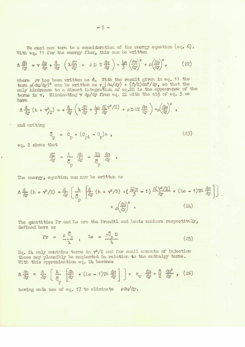
We must now- turn to a consideration of the energy equation (eq. 6). With eq. 11 for the energy flux, this can be written
fh. = v1 ay + -2 -a-- ( dY dY 3 ay
+ p D T + 0'7)2 + — au
)
2
(22)
where pv has been 1Tritten as rill. With the result given in eq. 11 the term p(du/dy)2 can be written as r (clu/dy) + W2)d.u2/dy, so that the only hindrance to a direct int.egraVion of eq.22 is the appearance of the terms in v. Eliminating v dp/dy from eq. 22 with the aid of eq. 5 we have
do (auy fy (1, 4. v2. + Aiva /2) + D /2 A dY + 3 cV
and writing
CP = C + (C p3. . - or)c (23)
eq. 2 shoi.7s that
aT 1 dh dY (31Y dy •
p p
The energy, equation can now be written as
The quantities Pr and Le are the Prandtl and Le-.-ris nucabers respeotively, defined here as
Pr p D Le = p X '
(25)
Eq. 21+ only contains terms in v2/2 end for small a counts of injection these may plausibly be neglected in relation to the enthalpy terms. With this approidmation eq. 24. 'becomes
ah d X dh !I du2 m + (Le - 1)TL 4-; + du r $ (26)
dY 7 ay + 2 dy 1
having made use of eq. 17 to eliminate pdu/dy.

(Le - 1)TA dc --- dU a + A [1 -(l cv,r)(1 + rtuir i) jc
The term involving T in this equation can i.e.
(Le - 1)(L03o WT)(1 -
be eliminn. ted via eqs. 1 and 20,
OTT) ( 1 + Igh..1/7) Sc-1
Eq. 26 can now be integrated to give
Itua [-ct- + (Le — 1)Tts trc- I UT + + w 2 117 (27) ( h — hw) A-
ID
Suffix w refers to quantities evaluated at the lower wall, y = 0 and in obtaining eq. 27 we have made use of the fact that
This can be i
- 1) TA t .
25.a .". 17
= + (Le Cp
seen from eqs. 11, 1 2 23 and
(28)
is the energy
transfer rate into the laLur wall.
The Crocco-type tr:ms-formation is now apiaied to eq. 27 with the result that
L
dh du (Le - 1) TA --Lc Pr (h h + Pr( UT + 1'1112/2 + a ) = du
.....(29)
and if we now write
T b
(30)
It is assumed from here on that Le and Pr am constant across the layer. Since Sc = Pr/Le this is consistent I.ith the previous assumption that Sc is also constant, In practice all of these dimensionless groups will vary to some extent with composition and we must regard the values used here as appropriate mean values .

for brevity, eq. 29, can be written.
1)Sc-1 ("Le - 1) (1 .,c )bSc(ub Mit • ••=• Ain .M.L
-117 au
ru?I+ 1/ ' b7 + -(1 - c i)(ub + 1)s 1
h
- Pr (u + 1/b)-1 (u + 1/b)72 1/2b2 + /I"; h
Eq. 31 can be integrated to yield.
f(u) h - f( o) htr = Pr I ( Vi; + hVi + E,(u)) f(u) (u + 1/b) -1 du ( 32)
o
where
(31)
f(u) = bFr (ub + 1)
+ A
(-( 1 - c ) ub + 1)Sc/(ta, 1) `'o
g(u) = (1/2b2 ) [ (ub + 1) 2 - 1 •
( 321 (32b
(Eq. 21 has ben used to elimin,, to 1-c in terms of co, U and b in eq. 32a, TT
and f( o) in eq. 32 is f(u) evaluated when u = 0).

3. Recover. : Enthalay:and Hcat Transfer Rate
Some general results can now be derived fro. co, 32. First -6a) notu that vthen u = U, h = h8 and if, in addition, ct = 0 then hw = hr, the
recovery enthalpy. It follows therefore that
hr = [ f(U)h8 4 Pri g(u) f(u) (u + dui
o
f(o) - Pr f(u)(u + 1/b)-1 du]
and in tenor, of this quantity,
p = (1/Er)
L f( 0)/ f( 11) ( U 1/b).4
0
These tuo quantities can be revritt,en in a Dore convenient form by defining dini.msionless functions f and g' are related to f and g in cgs. 32a and 32b, Thus we trite
fi(ul ) = (u' b' + 1 )."Pr i ± 6'1 1 41 .-c5)(ul b" + 1)S°/(b' 4. )Sc
= f(u)/b2rC Lo.-1 (33a)
(ui) = (ul b' + 2 - 1 = 2b2 g(u) / 2 33b)
there u = LIATI = bit, = 6/C . Thence it follows that
hr f'(1)1$ + (Pr e /2) ( f' )131-1(1 + 111131)-1 dal !
o 1 I L.
f ' ( o) - Pr -ID'0 f.'„ + u'bi ri du' i L (31k)
(1/pr) [ (14 (0)/ fl f (1 + 11'1)1 yi au) - (hr h)(1-T/u) (35)
wj -1 (hr -1k)brw

These expressions for h and qw are very unwieldy and little can be gained from an examination
hr them as they Aand. Consequently we must
resort to approximation in order to gain sore insight into the physical picture and it seems natural to attempt solutions for b' « 1. Referring to the definition of b' , this assumption is ecuivalent to setting
« 1. Physically this group of variables has a simple interpretation 1,1/
since AU is proportional to the flux of x-vise momentum induced in a direction away from the wall by the act of blowing into the shear layer, whilst T indicates the magnitude of the saris flux taking place towards
y = 0 as a result of the microscopic, molecular motions. Setting b' e<1 is equivalent to assuming that the amount of blowing is such as to cause only small decreases of skin friction.
It is worth noting that 11 is almost always multiplied by u in the integrals where is creates difficulties, so that a reasonable approximation should be found for quite large values of b'; at least the physics of the situation should be preserved in ouch circupstances.
After a certain amount of algebra it can be shown that
hr hro (Le 1)Sc Li hi s + (Pr U2/6)(2(Le 1)Sc 1 — Pr)]
(36)
eiw UPrir = (hro - hw) [1 -(b+ /2) - 1) Se L' :Pr)! (37)
(Le - 1)Sc L'h + (Pr 112/6) (1 -;Dr -(Le-1)Sc L'11
where hro is the recovery enthalpy with zero mass injection rate,
hro = h6 + Pr U2/2.
( Y1)
When both Pr and Le (and hence Sc also) are coual to unity the results 37 and 38 simplify to
hr = h ro ( 39)
-qrr 112r = (h h ) T
ro w w •
In this case then; injection of a foreign gas through the lower wall has no influence on the recovery enthalpy (since 06 = 0) and the form of the "Reynolds analogy" expression in eq. 40 is exactly like the no-injection one. However, it is clear from eq. 2 that at a given wall temperature, h will becoJoe greater or less than -Lie no-injection value of 0p TT/ depenffingonl.rhetherC. PI
>C or <C o (i.e. whether > 0 or <0).

- 1 0 -
Eq. 21 shows thLt an approximation to O,which is equivalent to those
made in deriving eqs. 36 and 37 is
mt Sc. b /
( a)
Then it follows that
hTI c CP T (1 + 411 . So b' ), (43)
or, in the case of Le = Pr = So = 1, the fractional increment in the wall enthalpy as a result of foreign gas injection is Al .
A further modification to the heat trmsfor rate arises via the reductions in T
17 brought about by gas injection. Assuming that i in
eq. 17 can be replaced by a properly weighted eonstant mean value, 5 say, it follows that
T = ra
exp(r.i8/ )
(4-)*
to a reasonable degree of approximation. Aside from any variations which may arise in the value of g duo to the j?resence of the foreign gas, the term TAJA is the zero injection skin friction. Eq. 44 shows that injection reduces shin friction by an amount equal to the mean rate of upwards trmsport of x-wise mancmtum which results from blowing, a plausible-looking first estimate.
Eq. 44 shows that significant skin friction reductions occur when
r!1 is comparable with 1778 . Simple kinetic theory gives T pal/3,
m mean molecular speed ( = a, speed of sound) end 6 = mean free
path, whence condition is ^}/GU where ii = U/a = Mach number
at outer edge of shear layer. This illustrates how very small el/rU
values are effective in reducing Tw, since Z/8 << 9 at reasonable
altitudes (pressures). It also suggests that bluing is more effective
at higher Mach numbers. The present theory is only valid if 0/ u <<1,
although this condition mod not be too strictly observed, see the remarks -proceeding eq. 36.

Still consider-111g the simple case where Le and 2r are unity, we can now write
(h h ) 1 L' - by
ro wo vio r' 2
( ifYY So'
(45)
`the re h Cp T. .
wo
The first term on the right-hand side corresponds to zero-injection heat transfer, the remaining terms express the effect of injection. Since 14 can be written as i 8/ u approximately, the last term in eq. 45 gives a reduction in - 5 equIll to (hro - hd6/2. This term is wholly
analogous to the term erU/2 in eq. h4, and represents the mean upwards transport of enthalpy as a result of injection. The second term in eq. 45 represents a potentially significant source of heat transfer rate reduction by C injection. The reduction in - C from this source is (C )T
P1 P w a quantity which expresses the loss of enthalpy difference across the layer which results from the injection of a gas with a large heat capacity, C .
Pi It is interesting to observe that this quantity my be negative and it follows from eq. 45 that the effect of injection as summarised in the right-hand side of this equation may lead to a increase in r rate if 2(1 - C
P1 ./C ) > (Tr
'V7 - 1), where Cp r =1).ro • (For example,
if o
CPi /CP = 1/2 the heat transfer rate is increased if Tro/TW < 2).
That is to say, it seems quite possible that the incvease in heat flux driving 'ei-ce arising from injection of the twrongt gas can more than counterbalance the effects of convection of energy away from the surface by blowing. !la C.I'1rr ads.
For this reason it seems advisable to choose a light gas for heat transfer reduction. Within limits the molar heats of gases do not vary a great deal and a large C is perhaps more easily obtained by selecting
Pi a gas of small molecular weight, rather than one of corm_ lax structure with many modes of communicable energy storage.
So far we haw overlooked the possibility that 77 may be favourably or unfavourably affected by injection. So long as the amounts of injection are small, so that c remains small throughout the layer it is .possible that p is not much affected, although it is difficult to generalise here. Suffice it to say that light gases have lower viscosities than the heavier ones in the main.
A further point of son importance when attempting an appraisal of boundary layer behaviour via the predictions of the present ultra-simplified analysis is that here the thickness 8 remains constant. In a boundary layer 3 will increase with increasing fa and will result in reductions of - (tivr and Tvr over and above those considered to date.
- 12 -
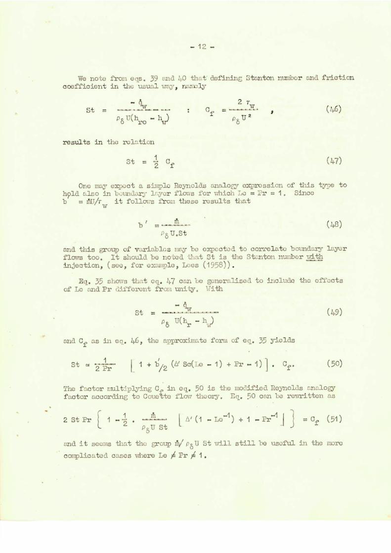
We note from eqs. 39 and 21_0 that defining Stanton number and friction coefficient in the usual nay, namely
St = - A 2 rw
= p8 U(hro - hu) p U 2
results in the relation
St = Cf (47)
One may expect a simple Reynolds analog expression of this type to hpld also in bcundar.- flows for which Le = Pr = 1. Since
= laT/7- it follows from these results that Ci
(z8) Pis U .St
and this group of variables nay be expected to correlate boundary layer flows too. It should be noted that St is the Stanton nucler with injection, see, for oxal (plc , Lees (1958) ) .
••=0•Al.
Eel, 35 shows that eq. 1F7 can Le generalised to include the effects of Le and Pr different
and Cf as in eq.
1 St = 2 it
fro_: unity. With
st
yields
. Cf.
(49)
(50)
p 8 U(111, )
46, the approximate form of ec. 35
1 + b/2 Sc(ho - 1) + Pr - 1)1
The factor multiplying C in eq. 50 is the modified Reynolds .,2,nalogy factor according to CouAte flow theory. Eq. 50 can be rewritten as
2 St Pr [ 1 - 1 2 . ) 2-71. --- [ ,Y (1 - Lo-1) + 1 - Pr-1 i -I = Cf ( 1 )
P tr St
and it seems that the group rivi pa ll St will still be useful in the more
complicated cases there Le Pr 1.

- 13 -
Returnin to eqs 49 and 50 we find that
h h
2
Cf r
Cfo
( 1 + --b-( Al Sc(Le -1)+ Pr - 1)) • (Iwo h ro h wo •
where suffix o indicates zero injection value. A reasonable estimate for C.../Cfo is 1 - /2 and using the results in eqs. 36 and 37 we find
r after some 1.1.1nip-ulation that
Pr hti~ 4-(Pr U2/6)(1 - it -.(Le - 1) Al Sc) 1 - b'
h - h ro wo
(2 - Pr + Sc(Le - 1)) . (52)
This result rednoes to the equivali-nt of eq. 24.5 when Le = Pr = 1 . The effects of Le and Pr different from unity are difficult to assess in general, certainly the last term in eq. 52 is favourably affected by the situation Le > 1, Pr < 1 provided > 0 . (Note Sc(Le - 1) = Pr - So and Pr > So in this case). This does not follow in the case of the second term however and the situation depends on the relative magnitudes of all the par-zacters present.

-14--
4. Sublimation
If the conditions arc right, it nay harpen that the lower wall reaches a temerature at which sublimation of the wall material takes place, resulting in the "injection" of a foreign gas into the shear layer. In this event the quantity r is no longer a free, or independent, variable but must be related in some way to the heat transfer rate and the latent heat of the subliming material.
To illustrate this effect in as simple a fashion as possible we will assume that Pr and Le for the resulting gas mixture are unity and use eqs. 39 and 40. To achieve a steady state it is necessary to allow the lower wall material to move upwards at a rate just sufficient to keep the subliming interface at the position y = 0. Allowing for this "convection" of solid material up-,-L.r.ls towards y = 0, the energy balance for the solid is
dT leT 1i1 Cb
=b
(Specific heat Cb and conductivity 1.b are assumed constant). Then
t'L; = Cb (T Tb)
where T1, is the solid's te7,perature at a position so far inside the wall that dT7dy is sensibly zero. It follows at once that
T lb = (Tyr - Tb)exp(Al Cb y/ Xb)
and the heat transfer rate LI-to the solid just below the subliming interface is
b ($) y 0 - Cb (Tw
Tb)
(56)
This rate must be matched to the value of -(l at y = 0+, taking
account of the fact that the material absorbs en aDount of latent heat L whilst undergoing the change of phase from solid to gas. In other words
elw = (L Cb (Tw - Tb)) = ALL', (57)
say.
With the constant mean viscosity assumption - 41,7 can be written (see eq. 45) as
- 4ff = (hTO - hWO ro )17/5 n w0
h Al (h h )/2] . (58) wo
(53)
(54)
(55)

- 15 -
It follows at once from eq. 57 that
h h )/'2)-1 . (59) - h )(1_ + h ro wo wo ro
This result exerplifies the self-regulating character of the sublimation process. The mass lost through sublimation is seen to decrease as t and A' increase, other things being equal. Prom a structural viewpoint then, it is best to choose an ablating material :hose latent heat of sublimation is high and which degrades into a gas with as high a specific heat as possible. This would suggest that the reductions in - 4,7 arising from ablation may be come small, since el itself is small. Putting 59 into 58 gives
, 4irr = (hro pro) h g/8)L we (L + h A'+(hro hwe )/12) (60)
So long as LI > 0 this value is alwys loss than the no-ablation value, but it will not be much below it if L becomes very large.
However, - kr is not of primary importance here. Rather are we concerned with the heat flux into the wall, which ecis. 56 and 57 show to be given by
i 7 rn L = Cis (6i)
say. Thus
— = (h ro 11wo) [ 1
L + h A' + (hr0
hvie )/2
(62) L' + h + (hro ham )/2 we
Clearly - 4s reduces substantially in magnitude as L rises. (As L - 4s -. 0 ; note that although A 4 0 as L the
product AL remains finite and non--zero).
ItseemsreasonabletosuggestthatahighLard a high l PI wil
result in the nest effective and least wasteful tyre of surface sublimation.
The simple results just presented are not the whole story, however, because it has been tacitly assura;d throughout that Tu is known. In order to find -
s for example it is, of course, necessary to know T IFT
and this must be a function of the pressure in the shear layer.

mass, it fellows that the rate of
( xs/kT s- ) •
(s 1)!
sublimation, At,
/kT
is given by
❑ - g n
(63)
— 16 —
In other words, the final solution of the ablation problem .nest depend on a knowledEe of the variation of the vapour Lressure and latent heat of the wall ;:aterial with tcDperaturo, as we shall see.
The kinetic theory of the vapour pressure assullas (i) that the process of condensation requires no activation energy (so that every molecule of the condensing substance which strikes the wall returns to the solid phase) and, (ii) that the molecules in the solid phase behave as a number of multiple oscillators, no per unit area of surface,
vibrating -with a frequency V. The number of molecules vapourisinr (or subliming) from the solid phase is then given by the product of no'v
and the probability that they posses sufficient energy, Xs. If 2s
is the number of quadratic morrentuyt or displacement co-ordinates which contribute to this energy, this latter probability is given -Ly Berthoud's relation
4 -X (Ns/kT)s-1 e (s 1)!
( see lioe lwyn Ighe s loc . t) . Then if we write n for the number of molecul P S of the subliming mater -al which exist in unit volume of the vapour phase at the interface, II for their moan velocity and m for their
The velocity is given by
1_ = krOr m )
or, since the vapour pressure pv is given by n k T, r.e 0,7m write
-ri_ = (2.71• m kT)
1-jv
At esullibritzl Pi = 0 an the equilibrium va0our ).,rossure pvcq follows directly from eqs. 63 and 65. If n q is the corresponding
number density in the equilibrium state, the exi:rossion for rh can be written simply as
0 = (n n) = p-- (0 c) eq 4 ocl
-4r-••• •usr..m.-c .cra ..•mlimak -cm m. • 414•—•
* The treatment presented here is a nrecis of the account given by MbelwynHuEhes (1957) of vapourisation from the licluid phase.
(64)
(65)
(66)

- 17 -
where ceq and c are the corresponding nass fractions. A relation like
eq. 66 has been given by Scala (1958). It shou1d be noted that P is itself a function of e at given p and T, but if c« 1 we may reasonably estimate P as pm T where me is the mass of an external gas molecule.
Specialising the result 66 to apply at the lower wall, we know that w b (when Sc = 10 sue eq. 22) and for present pur?oses we can write
bi 61JA = AN U Sto , wo
(suffix o = no-injection case). Then
(P mete' (Q 1/4) c 6 N' Ifcq____, 1 + (p me/kTmr)(0m/24n8USto)
One can now equate 68 and 59, yielding a relation for Tw in terms of p, cweil (which is a function of p and Tm) and the latent heats etc. (Clearly As must be related to the latent heat Ti at the temperature T,).
The resulting equation is obviously not one for which an analytical solution can be obtained, but by stripping it down to the essentials some estimate of the trend of T with p can be made.
Assuming that As = L mg very roughly, and that L >> Cb(Tv - Tb)+
h A' + (h - h )/2 (which is consistent Lith the ana4sis taking 170 ro wo bi « 1) we can write via eqs. 68 and 59 etc.
-.EtykT s - 3/,
Yr A e = ( h o - C TN7)T17 /- 0 + Bp 2
17
-9 (69) r
where A and B are constants which depend on the materials involved. Then ary rise in p can be counterbalanced by a relatively small rise in Tw in general (via the exponential tem). The number of oscillators in each molecule which take part in the vapourisation processes is usually greater than 3, the value for monatomic moleanir's (i.e. s 3 3).
In practice eq. 69 implies that T increase (at a stagnation point, say) with increasing Mach numbd
v, r and decreasing altitude. By
how much must depend on the particular material which is involved.
Finally, it must be remembered that a wide group of materials pass through the liquid phase before vapourising, and that a liquid layer will exist between gas and solid. It goes without sayinc; that the presence of the liquid film will influence the final heat transfer rate to the interior of the wall, the rate of mass loss, etc. However a number of the broad conclusions reached above will apply to this typo of vapourisation process too.
(67)
(68)

- 18 -
5. References
Leos, L. ( 1 958) Combusti.in and Propulsion. 1. 3rd Aard Colloquium. 4-51 - 4-90. Per,gamon. Press. Tiondon.
2. litoolwyn-Hughes, E.A. (1957) P1 lysical Chemistry.
Porgamon ress, London.
3. Scala, S T. (1958) Journal_ Aero.Sciences, 25, 10, 655..656
4. Scala, S.7 -. (1960) Zournal Aero/S-oace Sciences, 27, 1, 1-12
Recommended