Repair Manual
K 1100 LT/RS
BMW AG Motorcycle DivisionAfter Sales

Published by BMW AG Motorcycle DivisionAfter SalesUX-VS-2
All rights reserved. Not to be reprinted, translated or duplicated either wholly or in part without prior written permission.Errors and omissions excepted; subject to technical amendment.
Produced in Germany 5/99
IntroductionThis repair manual will help you to perform all the main maintenance and repair work correctly and efficient-ly. If it is consulted regularly by workshop personnel it will form a useful addition to the theoretical and prac-tical knowledge acquired at the BMW Training Centre. It is a contribution towards achieving even higher Service quality.
All information in both text and illustrations refers to motorcycles in standard condition or with genuine BMW accessories installed, and not to motorcycles which have been modified in any way to depart from the manufacturer’s specification.
• The repair manual is structured in the logical sequence of the work to be performed: Removal, Disas-sembly, Repair, Assembly, Installation.
• The entire contents are divided into individual chapters, corresponding to the Construction Groups.
11 . 10
Chapter Page number within chapter
• Work to be performed during an Inspection is described in Group “00”. The various inspection routines are numbered I, II, III and IV. This numbering is repeated in the work descriptions which follow, so that work can take place without interruption.
• Use of the BMW special tools needed for certain tasks is described in the work instructions.
If the need arises, repair instructions are also issued in the form of Service Information. This information is of course incorporated into the next issue of the repair manual. We also recommend, as an additional source of information, the Electronic Parts Catalogue (ETC), which contains clear and easy-to-follow illus-trations.
If the work described here is restricted to a particular equipment specification, for instance if a specific op-tional extra (OE) is fitted, this is stated in square brackets at the start of the item concerned, e.g. [LT].
Please refer to the following pages as well for a description of other symbols used and how to work with it.
BMW AG Motorcycle DivisionAfter Sales
Published by: BMW AG Motorcycle DivisionAfter SalesUX-VS-2
D - 80788 München
All rights reserved. Not to be reprinted, translated or duplicated either wholly or in part without prior written permission.Errors and omissions excepted; subject to technical amendment.
Produced in Germany
Usage
Each chapter starts with the list of contents.
The list of contents is followed by the Technical Data table.
Chapter 00 “Maintenance and general instructions” details the handover checklist and lists all tightening torques and operating fluids.
Key to symbols
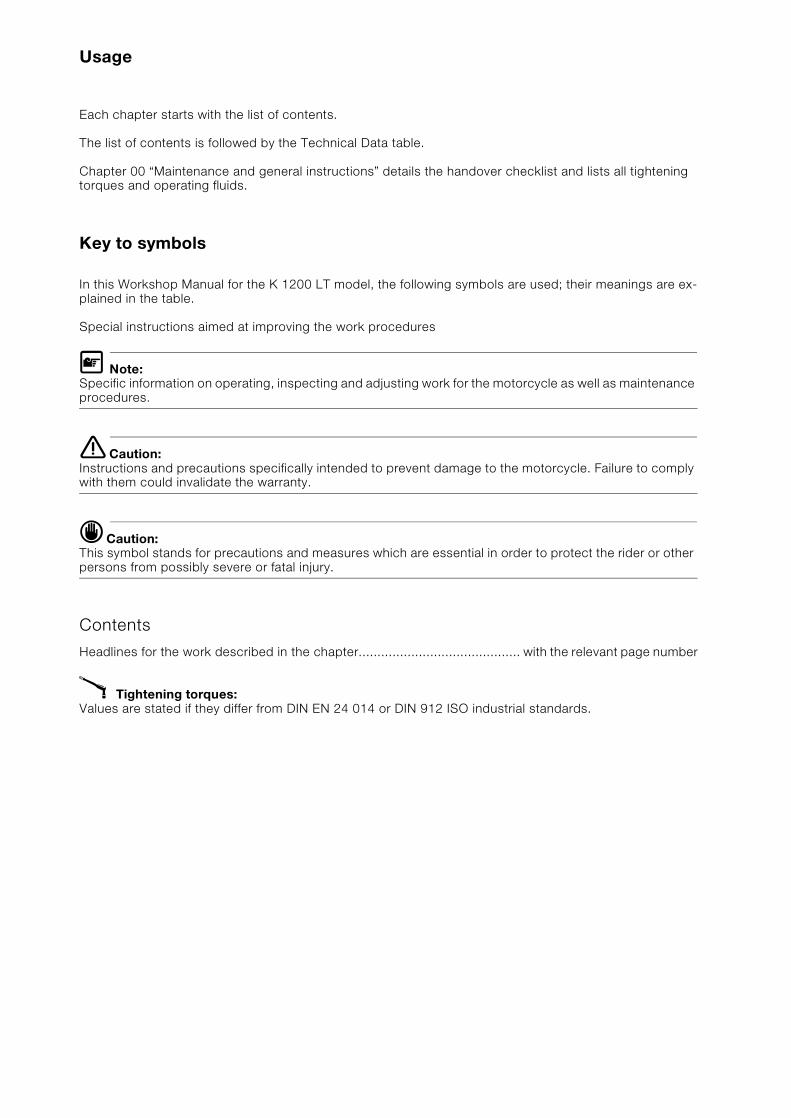
In this Workshop Manual for the K 1200 LT model, the following symbols are used; their meanings are ex-plained in the table.
Special instructions aimed at improving the work procedures
L Note:Specific information on operating, inspecting and adjusting work for the motorcycle as well as maintenance procedures.
e Caution:Instructions and precautions specifically intended to prevent damage to the motorcycle. Failure to comply with them could invalidate the warranty.
d Caution:This symbol stands for precautions and measures which are essential in order to protect the rider or other persons from possibly severe or fatal injury.
Contents
Headlines for the work described in the chapter........................................... with the relevant page number
X Tightening torques:Values are stated if they differ from DIN EN 24 014 or DIN 912 ISO industrial standards.
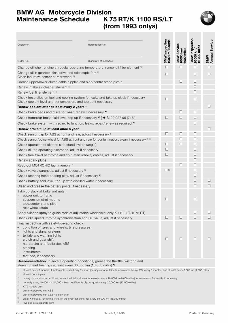
BMW AG Motorcycle DivisionMaintenance Schedule K 75 RT/K 1100 RS/LT
Order No. 01 71 9 799 131 UX-VS-2, 12/98 Printed in Germany
Customer Registration No.
Order No. Signature of mechanic BM
W In
spec
tion
1000
km/6
00m
ls
BM
W S
ervi
ce
1000
0 km
/60
00m
iles
BM
W In
spec
tion
2000
0 km
/ 12
000
mile
s
BM
W
An
nu
al S
erv
ice
Change oil when engine at regular operating temperature, renew oil filter element 1)
Change oil in gearbox, final drive and telescopic fork 2)
Clean inductive sensor at rear wheel 2)
Grease upper/lower clutch cable nipples and side/centre stand pivots
Renew intake air cleaner element 3)
Renew fuel filter element 4)
Check hose clips on fuel and cooling system for leaks and take up slack if necessaryCheck coolant level and concentration, and top up if necessary
Renew coolant after at least every 2 years *)
Check brake pads and discs for wear, renew if necessary *)
Check front/rear brake fluid level, top up if necessary *) [b SI 00 027 95 (716)]
Check brake system with regard to function, leaks; repair/renew as required *)
Renew brake fluid at least once a year
Check sensor gap for ABS at front and rear, adjust if necessary 6)
Check sensor/pulse wheel for ABS at front and rear for contamination, clean if necessary 6) 5)
Check operation of electric side stand switch (angle)
Check clutch operating clearance, adjust if necessary
Check free travel at throttle and cold-start (choke) cables, adjust if necessary
Renew spark plugs
Read out MOTRONIC fault memory 7)
Check valve clearences, adjust if necessary 8) 5)
Check steering head bearing play, adjust if necessary *)
Check battery acid level, top up with distilled water if necessary
Clean and grease the battery posts, if necessary
Take up slack at bolts and nuts: – power unit to frame– suspension strut mounts– side/center stand pivot– rear wheel studs
Apply silicone spray to guide rods of adjustable windshield (only K 1100 LT, K 75 RT)
Check idle speed, throttle synchronisation and CO value, adjust if necessary
Final inspection with safety/operating check:– condition of tyres and wheels, tyre pressures– lights and signal systems– telltale and warning lights– clutch and gear shift– handbrake and footbrake, ABS– steering– instruments– test ride, if necessary
Recommendation: In severe operating conditions, grease the throttle twistgrip and steering head bearings at least every 30,000 km (18,000 miles) *)
1) at least every 6 months; if motorcycle is used only for short journeys or at outside temperatures below 0°C, every 3 months, and at least every 3,000 km (1,800 miles)2) at least once a year3) in very dirty or dusty conditions, renew the intake air cleaner element every 10,000 km (6,000 miles), or even more frequently if necessary4) normally every 40,000 km (24,000 miles), but if fuel is of poor quality every 20,000 km (12,000 miles)5) K 75 models only6) only motorcycles with ABS7) only motorcycles with catalytic converter8) on all K models, renew the lining on the chain tensioner rail every 60,000 km (36,000 miles)
*) invoiced as a separate item
(from 1993 onlys)
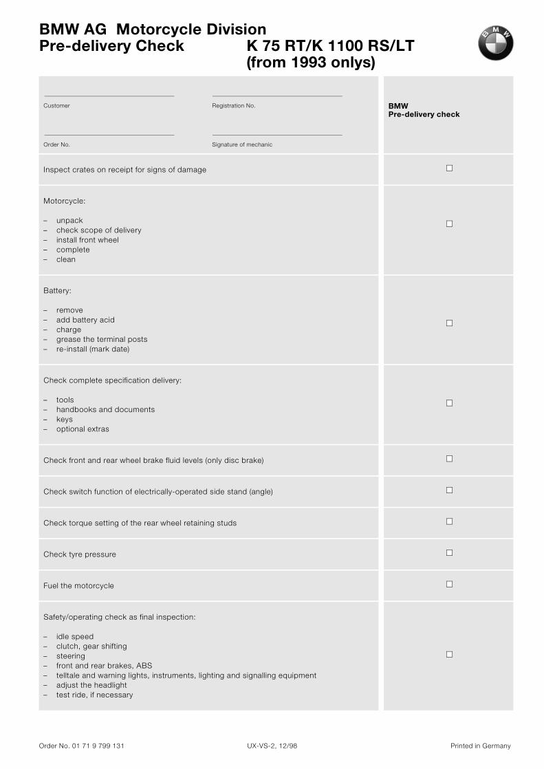
BMW AG Motorcycle DivisionPre-delivery Check K 75 RT/K 1100 RS/LT
Order No. 01 71 9 799 131 UX-VS-2, 12/98 Printed in Germany
Customer Registration No.
Order No. Signature of mechanic
BMW Pre-delivery check
Inspect crates on receipt for signs of damage
Motorcycle:
– unpack– check scope of delivery– install front wheel– complete– clean
Battery:
– remove– add battery acid– charge– grease the terminal posts– re-install (mark date)
Check complete specification delivery:
– tools– handbooks and documents– keys– optional extras
Check front and rear wheel brake fluid levels (only disc brake)
Check switch function of electrically-operated side stand (angle)
Check torque setting of the rear wheel retaining studs
Check tyre pressure
Fuel the motorcycle
Safety/operating check as final inspection:
– idle speed– clutch, gear shifting– steering– front and rear brakes, ABS– telltale and warning lights, instruments, lighting and signalling equipment– adjust the headlight– test ride, if necessary
(from 1993 onlys)
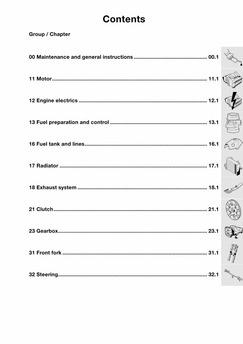
ContentsGroup / Chapter
00 Maintenance and general instructions ................................................. 00.1
11 Motor........................................................................................................ 11.1
12 Engine electrics ...................................................................................... 12.1
13 Fuel preparation and control ................................................................. 13.1
16 Fuel tank and lines.................................................................................. 16.1
17 Radiator ................................................................................................... 17.1
18 Exhaust system ....................................................................................... 18.1
21 Clutch....................................................................................................... 21.1
23 Gearbox.................................................................................................... 23.1
31 Front fork ................................................................................................. 31.1
32 Steering.................................................................................................... 32.1
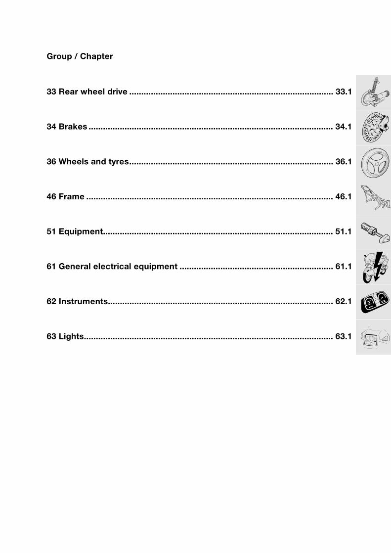
Group / Chapter
33 Rear wheel drive ..................................................................................... 33.1
34 Brakes ...................................................................................................... 34.1
36 Wheels and tyres..................................................................................... 36.1
46 Frame ....................................................................................................... 46.1
51 Equipment................................................................................................ 51.1
61 General electrical equipment ................................................................ 61.1
62 Instruments.............................................................................................. 62.1
63 Lights........................................................................................................ 63.1
00
Contents Page
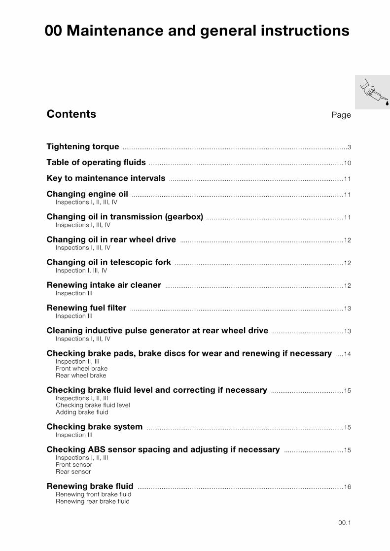
00 Maintenance and general instructions
Tightening torque .........................................................................................................................3
Table of operating fluids .........................................................................................................10
Key to maintenance intervals ..............................................................................................11
Changing engine oil ..................................................................................................................11Inspections I, II, III, IV
Changing oil in transmission (gearbox) ..........................................................................11Inspections I, III, IV
Changing oil in rear wheel drive ........................................................................................12Inspections I, III, IV
Changing oil in telescopic fork ...........................................................................................12Inspection I, III, IV
Renewing intake air cleaner ................................................................................................12Inspection III
Renewing fuel filter ...................................................................................................................13Inspection III
Cleaning inductive pulse generator at rear wheel drive .......................................13Inspections I, III, IV
Checking brake pads, brake discs for wear and renewing if necessary ....14Inspection II, IIIFront wheel brakeRear wheel brake
Checking brake fluid level and correcting if necessary .......................................15Inspections I, II, IIIChecking brake fluid levelAdding brake fluid
Checking brake system ..........................................................................................................15Inspection III
Checking ABS sensor spacing and adjusting if necessary ................................15Inspections I, II, IIIFront sensorRear sensor
Renewing brake fluid ...............................................................................................................16Renewing front brake fluidRenewing rear brake fluid
00.1
Contents Page
Checking function of electric switch on side stand and adjusting if necessary ....................................................................................................17
Inspections I, II, III
Checking clutch clearance and adjusting if necessary ........................................18Inspections I, III
Reading out Motronic defect code memory ...............................................................18Inspections II, III
Checking increased starting speed (choke) and adjusting if necessary ....19Inspections I, IIIChecking increased starting speed
Checking valve clearance and adjusting if necessary ..........................................20Inspections I, III
Adjusting valve clearance .....................................................................................................20Removing sprocketsRemoving camshaftsInstalling camshaftsInstalling sprocketsInstalling cylinder head cover
Checking steering bearing play and adjusting if necessary ..............................23Inspection III
Lubricating guide pins, adjustable screen ...................................................................24Inspections III, IV
Checking idle speed, synchronising and CO value and adjusting if necessary ......................................................................25
Inspections I, II, III, IVAdjusting idle speedAdjusting CO value without catalytic converter
00.2
00
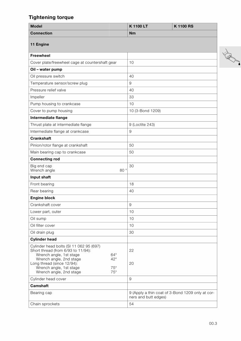
Tightening torque
Model K 1100 LT K 1100 RS
Connection Nm
11 Engine
Freewheel
Cover plate/freewheel cage at countershaft gear 10
Oil – water pump
Oil pressure switch 40
Temperature sensor/screw plug 9
Pressure relief valve 40
Impeller 33
Pump housing to crankcase 10
Cover to pump housing 10 (3-Bond 1209)
Intermediate flange
Thrust plate at intermediate flange 9 (Loctite 243)
Intermediate flange at crankcase 9
Crankshaft
Pinion/rotor flange at crankshaft 50
Main bearing cap to crankcase 50
Connecting rod
Big end capWrench angle 80 °
30
Input shaft
Front bearing 18
Rear bearing 40
Engine block
Crankshaft cover 9
Lower part, outer 10
Oil sump 10
Oil filter cover 10
Oil drain plug 30
Cylinder head
Cylinder head bolts (SI 11 062 95 (697)Short thread (from 6/93 to 11/94):
Wrench angle, 1st stageWrench angle, 2nd stage
Long thread (since 12/94):Wrench angle, 1st stageWrench angle, 2nd stage
64°42°
75°75°
22
20
Cylinder head cover 9
Camshaft
Bearing cap 9 (Apply a thin coat of 3-Bond 1209 only at cor-ners and butt edges)
Chain sprockets 54
00.3
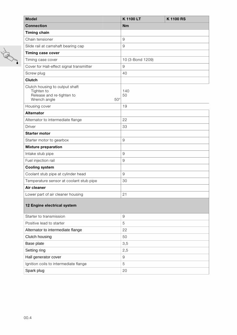
Timing chain
Chain tensioner 9
Slide rail at camshaft bearing cap 9
Timing case cover
Timing case cover 10 (3-Bond 1209)
Cover for Hall-effect signal transmitter 9
Screw plug 40
Clutch
Clutch housing to output shaftTighten toRelease and re-tighten toWrench angle 50°
14050
Housing cover 19
Alternator
Alternator to intermediate flange 22
Driver 33
Starter motor
Starter motor to gearbox 9
Mixture preparation
Intake stub pipe 9
Fuel injection rail 9
Cooling system
Coolant stub pipe at cylinder head 9
Temperature sensor at coolant stub pipe 30
Air cleaner
Lower part of air cleaner housing 21
12 Engine electrical system
Starter to transmission 9
Positive lead to starter 5
Alternator to intermediate flange 22
Clutch housing 50
Base plate 3,5
Setting ring 2,5
Hall generator cover 9
Ignition coils to intermediate flange 5
Spark plug 20
Model K 1100 LT K 1100 RS
Connection Nm
00.4
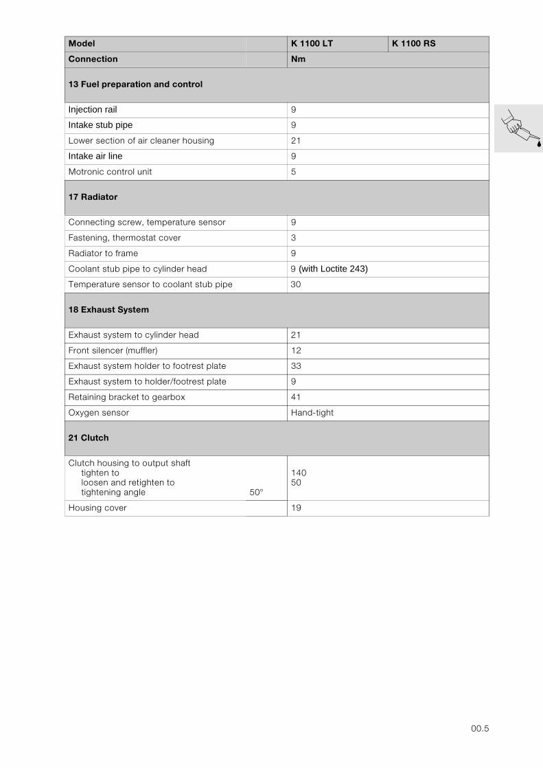
13 Fuel preparation and control
Injection rail 9
Intake stub pipe 9
Lower section of air cleaner housing 21
Intake air line 9
Motronic control unit 5
17 Radiator
Connecting screw, temperature sensor 9
Fastening, thermostat cover 3
Radiator to frame 9
Coolant stub pipe to cylinder head 9 (with Loctite 243)
Temperature sensor to coolant stub pipe 30
18 Exhaust System
Exhaust system to cylinder head 21
Front silencer (muffler) 12
Exhaust system holder to footrest plate 33
Exhaust system to holder/footrest plate 9
Retaining bracket to gearbox 41
Oxygen sensor Hand-tight
21 Clutch
Clutch housing to output shafttighten to loosen and retighten totightening angle 50°
14050
Housing cover 19
Model K 1100 LT K 1100 RS
Connection Nm
00.5
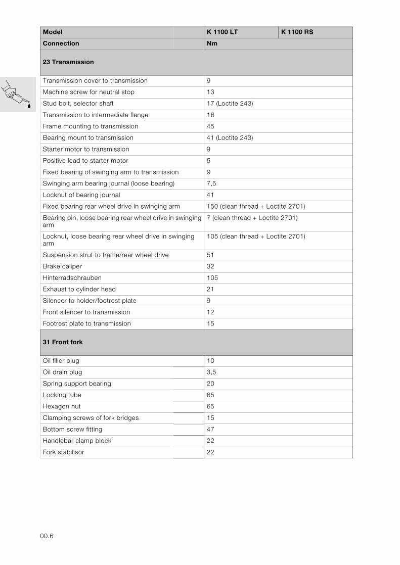
23 Transmission
Transmission cover to transmission 9
Machine screw for neutral stop 13
Stud bolt, selector shaft 17 (Loctite 243)
Transmission to intermediate flange 16
Frame mounting to transmission 45
Bearing mount to transmission 41 (Loctite 243)
Starter motor to transmission 9
Positive lead to starter motor 5
Fixed bearing of swinging arm to transmission 9
Swinging arm bearing journal (loose bearing) 7,5
Locknut of bearing journal 41
Fixed bearing rear wheel drive in swinging arm 150 (clean thread + Loctite 2701)
Bearing pin, loose bearing rear wheel drive in swinging arm
7 (clean thread + Loctite 2701)
Locknut, loose bearing rear wheel drive in swinging arm
105 (clean thread + Loctite 2701)
Suspension strut to frame/rear wheel drive 51
Brake caliper 32
Hinterradschrauben 105
Exhaust to cylinder head 21
Silencer to holder/footrest plate 9
Front silencer to transmission 12
Footrest plate to transmission 15
31 Front fork
Oil filler plug 10
Oil drain plug 3,5
Spring support bearing 20
Locking tube 65
Hexagon nut 65
Clamping screws of fork bridges 15
Bottom screw fitting 47
Handlebar clamp block 22
Fork stabilisor 22
Model K 1100 LT K 1100 RS
Connection Nm
00.6
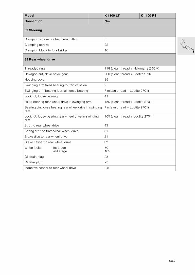
32 Steering
Clamping screws for handlebar fitting 5
Clamping screws 22
Clamping block to fork bridge 16
33 Rear wheel drive
Threaded ring 118 (clean thread + Hylomar SQ 32M)
Hexagon nut, drive bevel gear 200 (clean thread + Loctite 273)
Housing cover 35
Swinging arm fixed bearing to transmission 9
Swinging arm bearing journal, loose bearing 7 (clean thread + Loctite 2701)
Locknut, loose bearing 41
Fixed bearing rear wheel drive in swinging arm 150 (clean thread + Loctite 2701)
Bearing pin, loose bearing rear wheel drive in swinging arm
7 (clean thread + Loctite 2701)
Locknut, loose bearing rear wheel drive in swinging arm
105 (clean thread + Loctite 2701)
Strut to rear wheel drive 43
Spring strut to frame/rear wheel drive 51
Brake disc to rear wheel drive 21
Brake caliper to rear wheel drive 32
Wheel bolts: 1st stage2nd stage
50105
Oil drain plug 23
Oil filler plug 23
Inductive sensor to rear wheel drive 2,5
Model K 1100 LT K 1100 RS
Connection Nm
00.7
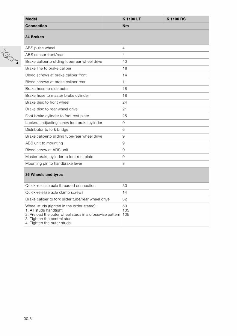
34 Brakes
ABS pulse wheel 4
ABS sensor front/rear 4
Brake caliperto sliding tube/rear wheel drive 40
Brake line to brake caliper 18
Bleed screws at brake caliper front 14
Bleed screws at brake caliper rear 11
Brake hose to distributor 18
Brake hose to master brake cylinder 18
Brake disc to front wheel 24
Brake disc to rear wheel drive 21
Foot brake cylinder to foot rest plate 25
Locknut, adjusting screw foot brake cylinder 9
Distributor to fork bridge 6
Brake caliperto sliding tube/rear wheel drive 9
ABS unit to mounting 9
Bleed screw at ABS unit 9
Master brake cylinder to foot rest plate 9
Mounting pin to handbrake lever 8
36 Wheels and tyres
Quick-release axle threaded connection 33
Quick-release axle clamp screws 14
Brake caliper to fork slider tube/rear wheel drive 32
Wheel studs (tighten in the order stated):1. All studs handtight2. Preload the outer wheel studs in a crosswise pattern3. Tighten the central stud4. Tighten the outer studs
50105105
Model K 1100 LT K 1100 RS
Connection Nm
00.8
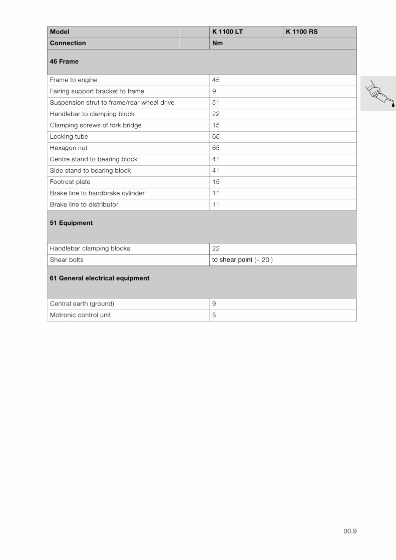
46 Frame
Frame to engine 45
Fairing support bracket to frame 9
Suspension strut to frame/rear wheel drive 51
Handlebar to clamping block 22
Clamping screws of fork bridge 15
Locking tube 65
Hexagon nut 65
Centre stand to bearing block 41
Side stand to bearing block 41
Footrest plate 15
Brake line to handbrake cylinder 11
Brake line to distributor 11
51 Equipment
Handlebar clamping blocks 22
Shear bolts to shear point (~ 20 )
61 General electrical equipment
Central earth (ground) 9
Motronic control unit 5
Model K 1100 LT K 1100 RS
Connection Nm
00.9
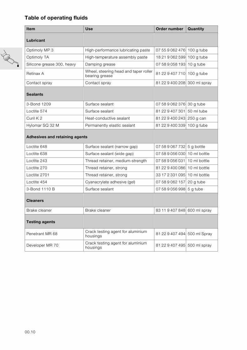
Table of operating fluids
Item Use Order number Quantity
Lubricant
Optimoly MP 3 High-performance lubricating paste 07 55 9 062 476 100 g tube
Optimoly TA High-temperature assembly paste 18 21 9 062 599 100 g tube
Silicone grease 300, heavy Damping grease 07 58 9 058 193 10 g tube
Retinax A Wheel, steering head and taper roller bearing grease 81 22 9 407 710 100 g tube
Contact spray Contact spray 81 22 9 400 208 300 ml spray
Sealants
3-Bond 1209 Surface sealant 07 58 9 062 376 30 g tube
Loctite 574 Surface sealant 81 22 9 407 301 50 ml tube
Curil K 2 Heat-conductive sealant 81 22 9 400 243 250 g can
Hylomar SQ 32 M Permanently elastic sealant 81 22 9 400 339 100 g tube
Adhesives and retaining agents
Loctite 648 Surface sealant (narrow gap) 07 58 9 067 732 5 g bottle
Loctite 638 Surface sealant (wide gap) 07 58 9 056 030 10 ml bottle
Loctite 243 Thread retainer, medium-strength 07 58 9 056 031 10 ml bottle
Loctite 270 Thread retainer, strong 81 22 9 400 086 10 ml bottle
Loctite 2701 Thread retainer, strong 33 17 2 331 095 10 ml bottle
Loctite 454 Cyanacrylate adhesive (gel) 07 58 9 062 157 20 g tube
3-Bond 1110 B Surface sealant 07 58 9 056 998 5 g tube
Cleaners
Brake cleaner Brake cleaner 83 11 9 407 848 600 ml spray
Testing agents
Penetrant MR 68 Crack testing agent for aluminium housings 81 22 9 407 494 500 ml Spray
Developer MR 70 Crack testing agent for aluminium housings 81 22 9 407 495 500 ml spray
00.10
Key to maintenance intervals
– Inspection at 1000 km (600 miles)I– BMW Service at 10,000 km (6000 miles))II– BMW Inspection at 20,000 km (12,000 miles)III– BMW Annual Service IV
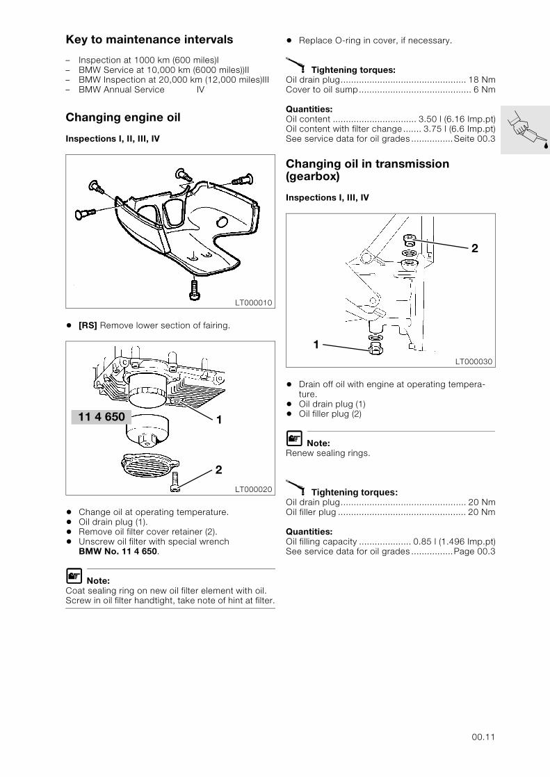
Changing engine oil
Inspections I, II, III, IV
• [RS] Remove lower section of fairing.
• Change oil at operating temperature.• Oil drain plug (1).• Remove oil filter cover retainer (2).• Unscrew oil filter with special wrench
BMW No. 11 4 650.
L Note:Coat sealing ring on new oil filter element with oil. Screw in oil filter handtight, take note of hint at filter.
• Replace O-ring in cover, if necessary.
X Tightening torques:Oil drain plug................................................ 18 NmCover to oil sump........................................... 6 Nm
Quantities:Oil content ................................ 3.50 l (6.16 Imp.pt)Oil content with filter change....... 3.75 l (6.6 Imp.pt)See service data for oil grades ................Seite 00.3
Changing oil in transmission (gearbox)
Inspections I, III, IV
• Drain off oil with engine at operating tempera-ture.
• Oil drain plug (1)• Oil filler plug (2)
L Note:Renew sealing rings.
X Tightening torques:Oil drain plug................................................ 20 NmOil filler plug ................................................. 20 Nm
Quantities:Oil filling capacity .................... 0.85 l (1.496 Imp.pt)See service data for oil grades ................Page 00.3
LT000010
LT000020
1
2
11 4 650
LT000030
2
1
00.11
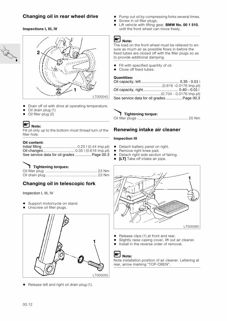
Changing oil in rear wheel drive
Inspections I, III, IV
• Drain off oil with drive at operating temperature.• Oil drain plug (1)• Oil filler plug (2)
L Note:Fill oil only up to the bottom-most thread turn of the filler hole.
Oil content:Initial filling ................................ 0.25 l (0.44 Imp.pt)Oil changes ............................. 0.35 l (0.616 Imp.pt)See service data for oil grades ............... Page 00.3
X Tightening torques:Oil filler plug ................................................ 23 NmOil drain plug................................................ 23 Nm
Changing oil in telescopic fork
Inspection I, III, IV
• Support motorcycle on stand.• Unscrew oil filler plugs.
• Release left and right oil drain plug (1).
• Pump out oil by compressing forks several times.• Screw in oil filler plugs.• Lift vehicle with lifting gear, BMW No. 00 1 510,
until the front wheel can move freely.
L Note:The load on the front wheel must be relieved to en-sure as much air as possible flows in before the fixed tubes are closed off with the filler plugs so as to provide additional damping.
• Fill with specified quantity of oil.• Close off fixed tubes.
Quantities:Oil capacity, left .................................... 0.35 - 0.01 l............................................(0.616 -0.0176 Imp.pt)Oil capacity, right................................. 0.40 – 0.01 l ...........................................(0.704 - 0.0176 Imp.pt)See service data for oil grades................Page 00.3
X Tightening torque:Oil filler plugs ............................................... 20 Nm
Renewing intake air cleaner
Inspection III
• Detach battery panel on right.• Remove right knee pad.• Detach right side section of fairing.• [LT] Take off intake air pipe.
• Release clips (1) at front and rear.• Slightly raise casing cover, lift out air cleaner.• Install in the reverse order of removal.
L Note:Note installation position of air cleaner. Lettering at rear, arrow marking “TOP-OBEN”.
LT000040
2
1
LT000050
1
LT000060
1
00.12
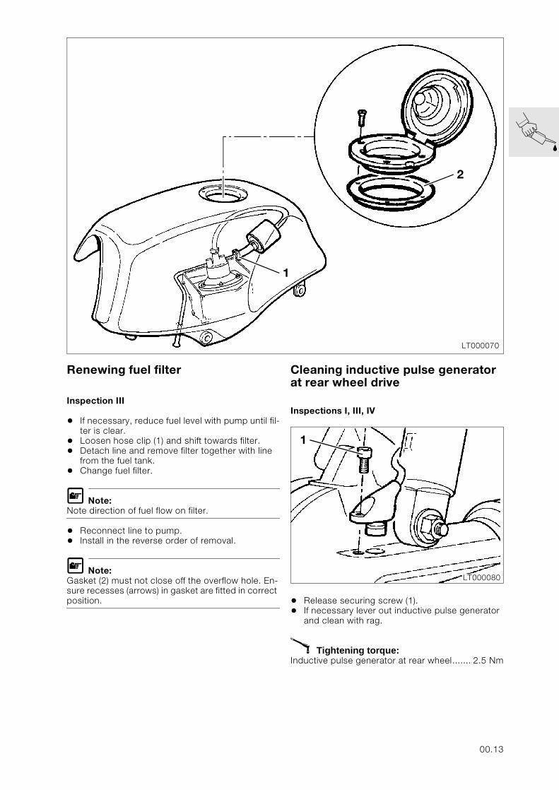
Renewing fuel filter
Inspection III
• If necessary, reduce fuel level with pump until fil-ter is clear.
• Loosen hose clip (1) and shift towards filter.• Detach line and remove filter together with line
from the fuel tank.• Change fuel filter.
L Note:Note direction of fuel flow on filter.
• Reconnect line to pump. • Install in the reverse order of removal.
L Note:Gasket (2) must not close off the overflow hole. En-sure recesses (arrows) in gasket are fitted in correct position.
Cleaning inductive pulse generator at rear wheel drive
Inspections I, III, IV
• Release securing screw (1).• If necessary lever out inductive pulse generator
and clean with rag.
X Tightening torque:Inductive pulse generator at rear wheel....... 2.5 Nm
LT000070
1
2
LT000080
1
00.13
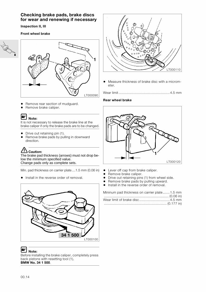
Checking brake pads, brake discs for wear and renewing if necessaryInspection II, III
Front wheel brake
• Remove rear section of mudguard.• Remove brake caliper.
L Note:It is not necessary to release the brake line at the brake caliper if only the brake pads are to be changed.
• Drive out retaining pin (1).• Remove brake pads by pulling in downward
direction.
e Caution:The brake pad thickness (arrows) must not drop be-low the minimum specified value.Change pads only as complete sets.
Min. pad thickness on carrier plate....1.5 mm (0.06 in)
• Install in the reverse order of removal.
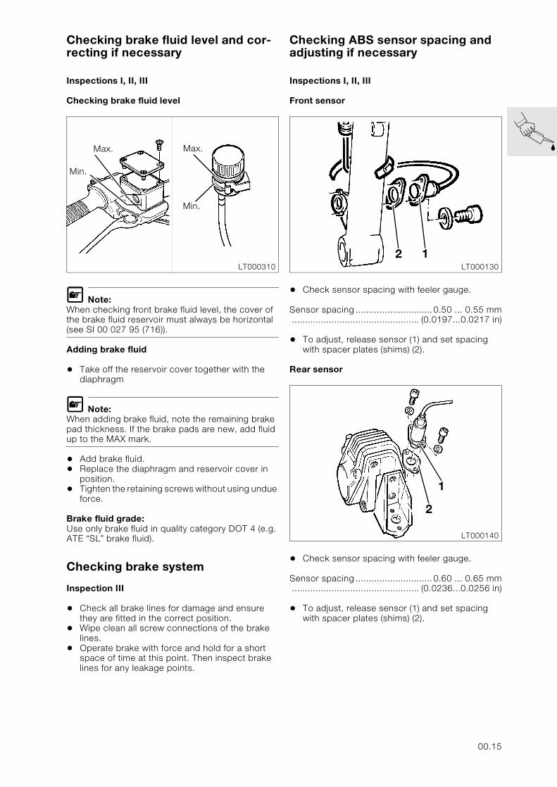
L Note:Before installing the brake caliper, completely press back pistons with resetting tool (1), BMW No. 34 1 500.
• Measure thickness of brake disc with a microm-eter.
Wear limit ....................................................4.5 mm
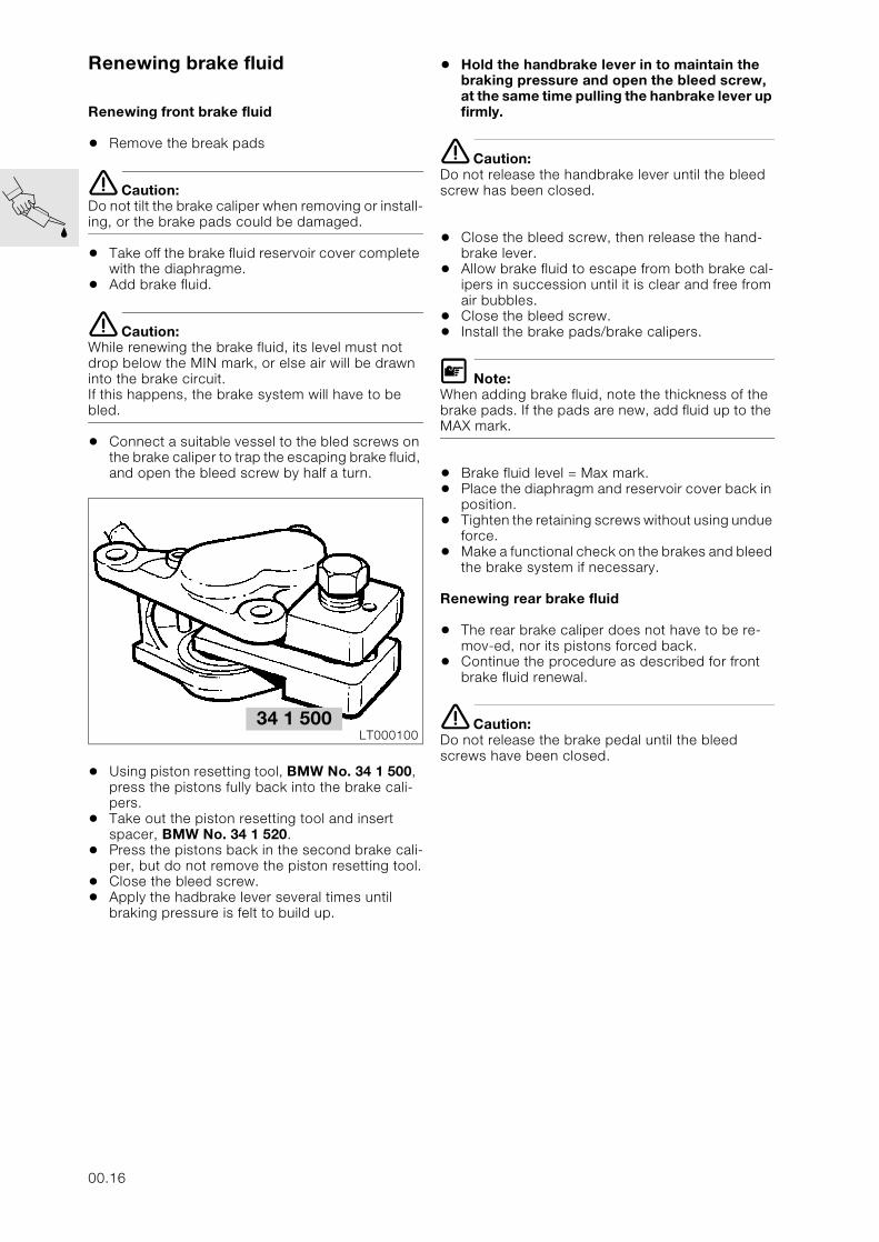
Rear wheel brake
• Lever off cap from brake caliper.• Remove brake caliper.• Drive out retaining pins (1) from wheel side.• Remove brake pads by pulling upward.• Install in the reverse order of removal.
Mininum pad thickness on carrier plate.......1.5 mm.................................................................. (0.06 in)Wear limit of brake disc...............................4.5 mm................................................................ (0.177 in)
LT000090
1
34 1 500LT000100
LT000110
LT000120
1
00.14
Checking brake fluid level and cor-recting if necessary
Inspections I, II, III
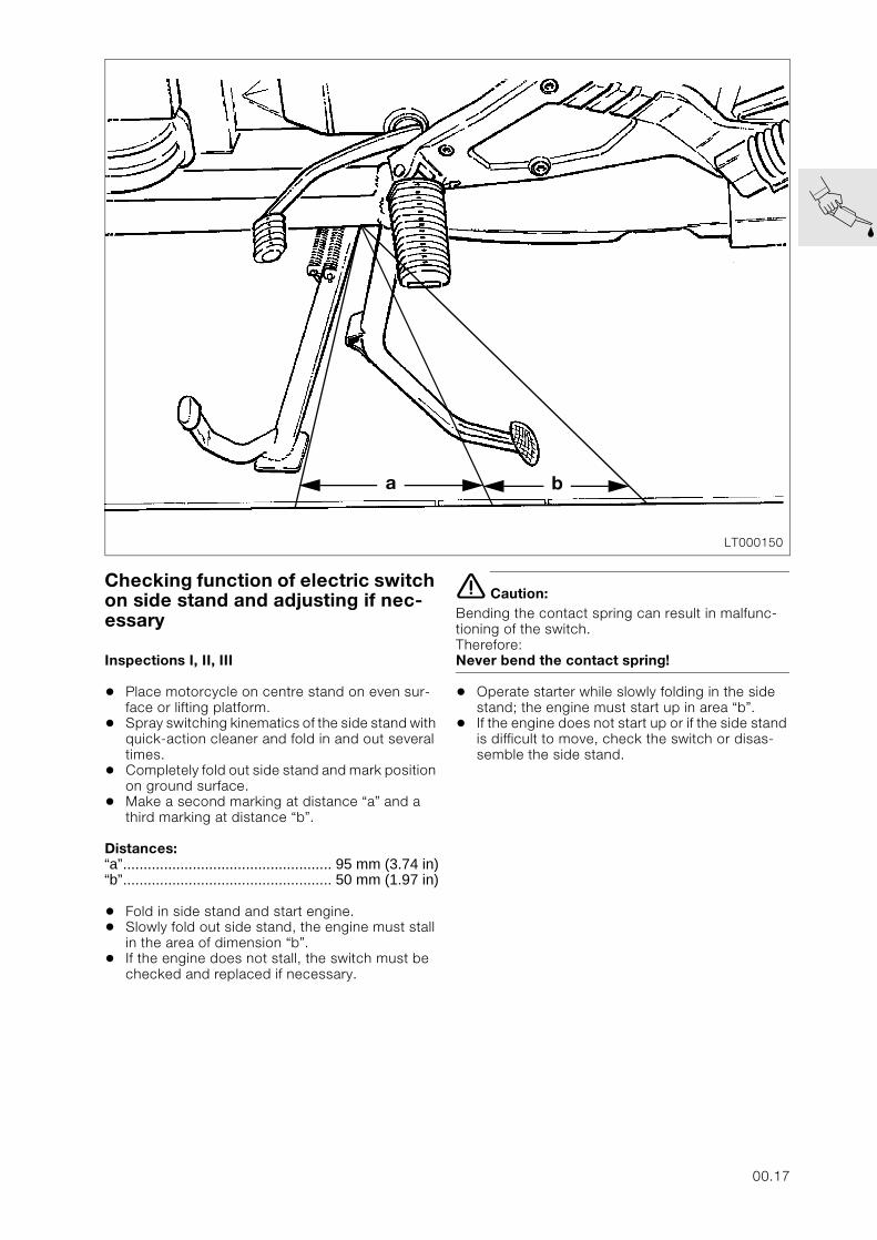
Checking brake fluid level
L Note:When checking front brake fluid level, the cover of the brake fluid reservoir must always be horizontal (see SI 00 027 95 (716)).
Adding brake fluid
• Take off the reservoir cover together with the diaphragm
L Note:When adding brake fluid, note the remaining brake pad thickness. If the brake pads are new, add fluid up to the MAX mark.
• Add brake fluid.• Replace the diaphragm and reservoir cover in
position.• Tighten the retaining screws without using undue
force.
Brake fluid grade:Use only brake fluid in quality category DOT 4 (e.g. ATE “SL” brake fluid).
Checking brake system
Inspection III
• Check all brake lines for damage and ensure they are fitted in the correct position.
• Wipe clean all screw connections of the brake lines.
• Operate brake with force and hold for a short space of time at this point. Then inspect brake lines for any leakage points.
Checking ABS sensor spacing and adjusting if necessary
Inspections I, II, III
Front sensor
• Check sensor spacing with feeler gauge.
Sensor spacing .............................0.50 ... 0.55 mm................................................ (0.0197...0.0217 in)
• To adjust, release sensor (1) and set spacing with spacer plates (shims) (2).
Rear sensor
• Check sensor spacing with feeler gauge.
Sensor spacing .............................0.60 ... 0.65 mm................................................ (0.0236...0.0256 in)
• To adjust, release sensor (1) and set spacing with spacer plates (shims) (2).
LT000310
Max.
Min.
Max.
Min.
LT000130
2 1
LT000140
2
1
00.15
Renewing brake fluid
Renewing front brake fluid
• Remove the break pads
e Caution:Do not tilt the brake caliper when removing or install-ing, or the brake pads could be damaged.
• Take off the brake fluid reservoir cover complete with the diaphragme.
• Add brake fluid.
e Caution:While renewing the brake fluid, its level must not drop below the MIN mark, or else air will be drawn into the brake circuit. If this happens, the brake system will have to be bled.
• Connect a suitable vessel to the bled screws on the brake caliper to trap the escaping brake fluid, and open the bleed screw by half a turn.
• Using piston resetting tool, BMW No. 34 1 500, press the pistons fully back into the brake cali-pers.
• Take out the piston resetting tool and insert spacer, BMW No. 34 1 520.
• Press the pistons back in the second brake cali-per, but do not remove the piston resetting tool.
• Close the bleed screw.• Apply the hadbrake lever several times until
braking pressure is felt to build up.
• Hold the handbrake lever in to maintain the braking pressure and open the bleed screw, at the same time pulling the hanbrake lever up firmly.
e Caution:Do not release the handbrake lever until the bleed screw has been closed.
• Close the bleed screw, then release the hand-brake lever.
• Allow brake fluid to escape from both brake cal-ipers in succession until it is clear and free from air bubbles.
• Close the bleed screw.• Install the brake pads/brake calipers.
L Note:When adding brake fluid, note the thickness of the brake pads. If the pads are new, add fluid up to the MAX mark.
• Brake fluid level = Max mark.• Place the diaphragm and reservoir cover back in
position.• Tighten the retaining screws without using undue
force.• Make a functional check on the brakes and bleed
the brake system if necessary.
Renewing rear brake fluid
• The rear brake caliper does not have to be re-mov-ed, nor its pistons forced back.
• Continue the procedure as described for front brake fluid renewal.
e Caution:Do not release the brake pedal until the bleed screws have been closed.
34 1 500LT000100
00.16
Checking function of electric switch on side stand and adjusting if nec-essary
Inspections I, II, III
• Place motorcycle on centre stand on even sur-face or lifting platform.
• Spray switching kinematics of the side stand with quick-action cleaner and fold in and out several times.
• Completely fold out side stand and mark position on ground surface.
• Make a second marking at distance “a” and a third marking at distance “b”.
Distances:“a”................................................... 95 mm (3.74 in)“b”................................................... 50 mm (1.97 in)
• Fold in side stand and start engine.• Slowly fold out side stand, the engine must stall
in the area of dimension “b”.• If the engine does not stall, the switch must be
checked and replaced if necessary.
e Caution:Bending the contact spring can result in malfunc-tioning of the switch.Therefore:Never bend the contact spring!
• Operate starter while slowly folding in the side stand; the engine must start up in area “b”.
• If the engine does not start up or if the side stand is difficult to move, check the switch or disas-semble the side stand.
LT000150
a b
00.17
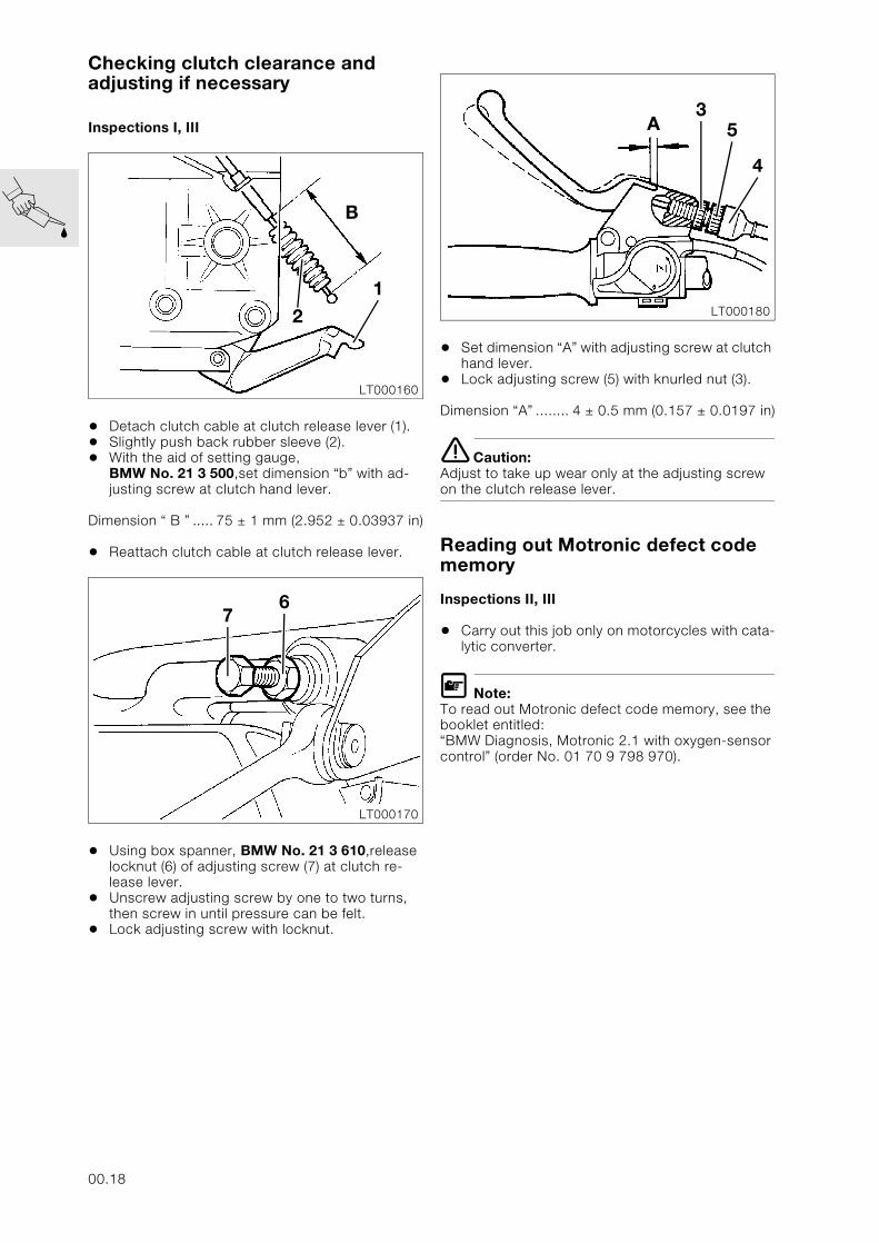
Checking clutch clearance and adjusting if necessary
Inspections I, III
• Detach clutch cable at clutch release lever (1).• Slightly push back rubber sleeve (2).• With the aid of setting gauge,
BMW No. 21 3 500,set dimension “b” with ad-justing screw at clutch hand lever.
Dimension “ B ” ..... 75 ± 1 mm (2.952 ± 0.03937 in)
• Reattach clutch cable at clutch release lever.
• Using box spanner, BMW No. 21 3 610,release locknut (6) of adjusting screw (7) at clutch re-lease lever.
• Unscrew adjusting screw by one to two turns, then screw in until pressure can be felt.
• Lock adjusting screw with locknut.
• Set dimension “A” with adjusting screw at clutch hand lever.
• Lock adjusting screw (5) with knurled nut (3).
Dimension “A” ........ 4 ± 0.5 mm (0.157 ± 0.0197 in)
e Caution:Adjust to take up wear only at the adjusting screw on the clutch release lever.
Reading out Motronic defect code memory
Inspections II, III
• Carry out this job only on motorcycles with cata-lytic converter.
L Note:To read out Motronic defect code memory, see the booklet entitled: “BMW Diagnosis, Motronic 2.1 with oxygen-sensor control” (order No. 01 70 9 798 970).
LT000160
21
B
LT000170
76
LT000180
5
4
3A
00.18
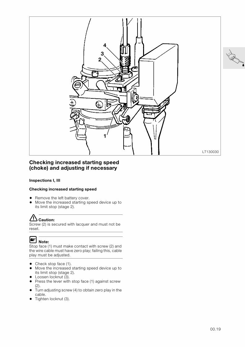
Checking increased starting speed (choke) and adjusting if necessary
Inspections I, III
Checking increased starting speed
• Remove the left battery cover.• Move the increased starting speed device up to
its limit stop (stage 2).
e Caution:Screw (2) is secured with lacquer and must not be reset.
L Note:Stop face (1) must make contact with screw (2) and the wire cable must have zero play; failing this, cable play must be adjusted.
• Check stop face (1).• Move the increased starting speed device up to
its limit stop (stage 2).• Loosen locknut (3).• Press the lever with stop face (1) against screw
(2).• Turn adjusting screw (4) to obtain zero play in the
cable.• Tighten locknut (3).
LT130030
1
23
4
00.19
Checking valve clearance and adjusting if necessary
Inspections I, III
e Caution:Never unscrew the spark plugs before measuring the valve clearance. Carbon particles may settle be-hind an exhaust valve head and falsify the measured result.
• [RS] Remove bottom section of fairing .• Remove left side section of fairing.• Remove cylinder head cover.• Remove cover for Hall generator.• Only crank engine at the crankshaft (counter-
clockwise!).• Measure valve clearance with feeler gauge.• Max. engine temperature 35 °C.• Determine the replacement tappet by way of
nominal/actual value comparison.
Valve clearance:Inlet .................0.15 - 0.20 mm (0.0059 - 0.0079 in)Exhaust ...........0.25 - 0.30 mm (0.0098 - 0.0118 in)
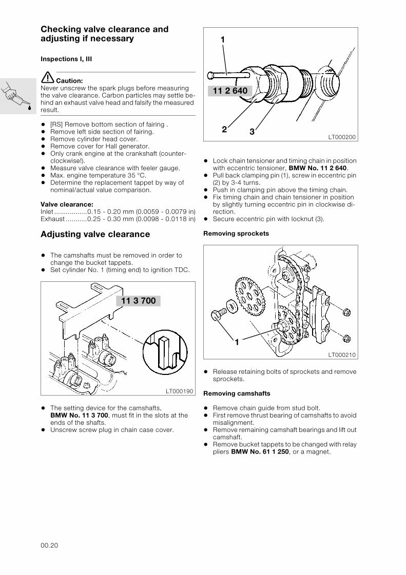
Adjusting valve clearance
• The camshafts must be removed in order to change the bucket tappets.
• Set cylinder No. 1 (timing end) to ignition TDC.
• The setting device for the camshafts, BMW No. 11 3 700, must fit in the slots at the ends of the shafts.
• Unscrew screw plug in chain case cover.
• Lock chain tensioner and timing chain in position with eccentric tensioner, BMW No. 11 2 640.
• Pull back clamping pin (1), screw in eccentric pin (2) by 3-4 turns.
• Push in clamping pin above the timing chain.• Fix timing chain and chain tensioner in position
by slightly turning eccentric pin in clockwise di-rection.
• Secure eccentric pin with locknut (3).
Removing sprockets
• Release retaining bolts of sprockets and remove sprockets.
Removing camshafts
• Remove chain guide from stud bolt.• First remove thrust bearing of camshafts to avoid
misalignment.• Remove remaining camshaft bearings and lift out
camshaft.• Remove bucket tappets to be changed with relay
pliers BMW No. 61 1 250, or a magnet.
11 3 700
LT000190
11 2 640
LT000200
1
2 3
LT000210
1
00.20
L Note:
Only the bucket tappets replaced during the 1000 km (600 miles) inspection can be re-used.
Installing camshafts
• The camshafts are marked to ensure they cannot be confused.
e Caution:Camshaft identification.Inlet: Groove after the thrust bearingExhaust: No groove
• The camshaft bearing caps are also identified. Inlet side: Odd numbersExhaust side: Even numbers
• The order is ascending from the front (timing end) to the rear.
• Install camshafts with the bearing points slightly oiled.
• Evenly tighten bearing cap working from the in-side towards the outside.
• Install thrust bearing (timing end) last.
X Tightening torque:Bearing cap................................................... 9 Nm
• Turn camshafts so that the grooves at the rear ends are positioned vertically with respect to the cylinder head.
• The grooves at the front end must face the inside towards the crankshaft.
• Fit setting device, BMW No. 11 3 700, and se-cure to the bearings of the camshaft.
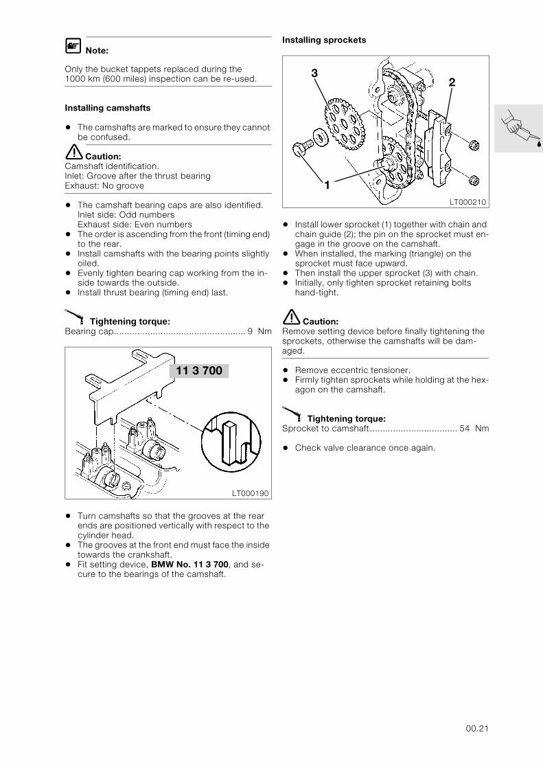
Installing sprockets
• Install lower sprocket (1) together with chain and chain guide (2); the pin on the sprocket must en-gage in the groove on the camshaft.
• When installed, the marking (triangle) on the sprocket must face upward.
• Then install the upper sprocket (3) with chain.• Initially, only tighten sprocket retaining bolts
hand-tight.
e Caution:Remove setting device before finally tightening the sprockets, otherwise the camshafts will be dam-aged.
• Remove eccentric tensioner. • Firmly tighten sprockets while holding at the hex-
agon on the camshaft.
X Tightening torque:Sprocket to camshaft.................................. 54 Nm
• Check valve clearance once again.
11 3 700
LT000190
LT000210
1
32
00.21
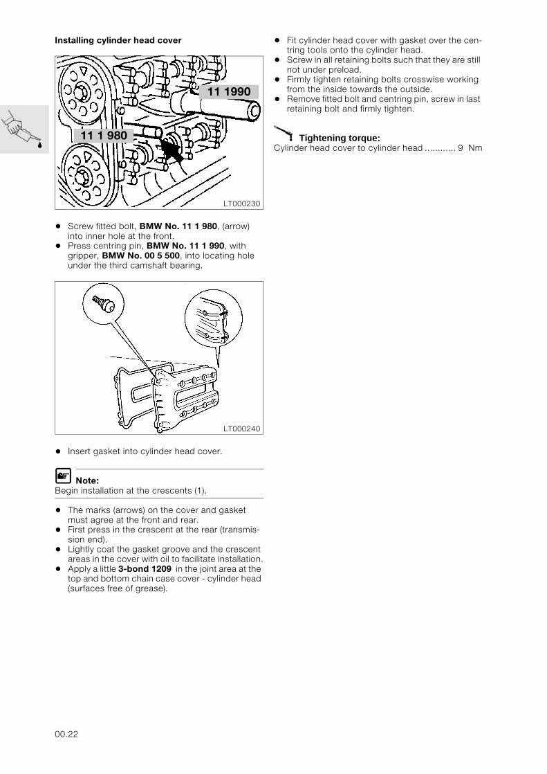
Installing cylinder head cover
• Screw fitted bolt, BMW No. 11 1 980, (arrow) into inner hole at the front.
• Press centring pin, BMW No. 11 1 990, with gripper, BMW No. 00 5 500, into locating hole under the third camshaft bearing.
• Insert gasket into cylinder head cover.
L Note:Begin installation at the crescents (1).
• The marks (arrows) on the cover and gasket must agree at the front and rear.
• First press in the crescent at the rear (transmis-sion end).
• Lightly coat the gasket groove and the crescent areas in the cover with oil to facilitate installation.
• Apply a little 3-bond 1209 in the joint area at the top and bottom chain case cover - cylinder head (surfaces free of grease).
• Fit cylinder head cover with gasket over the cen-tring tools onto the cylinder head.
• Screw in all retaining bolts such that they are still not under preload.
• Firmly tighten retaining bolts crosswise working from the inside towards the outside.
• Remove fitted bolt and centring pin, screw in last retaining bolt and firmly tighten.
X Tightening torque:Cylinder head cover to cylinder head ............ 9 Nm
11 1 980
LT000230
11 1990
LT000240
00.22
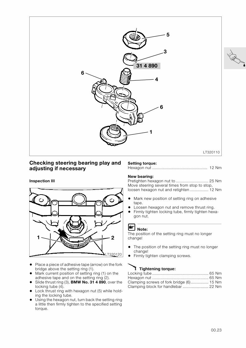
Checking steering bearing play and adjusting if necessary
Inspection III
• Place a piece of adhesive tape (arrow) on the fork bridge above the setting ring (1).
• Mark current position of setting ring (1) on the adhesive tape and on the setting ring (2).
• Slide thrust ring (3), BMW No. 31 4 890, over the locking tube (4).
• Lock thrust ring with hexagon nut (5) while hold-ing the locking tube.
• Using the hexagon nut, turn back the setting ring a little then firmly tighten to the specified setting torque.
Setting torque:Hexagon nut ............................................... 12 Nm
New bearing:Pretighten hexagon nut to ............................ 25 NmMove steering several times from stop to stop, loosen hexagon nut and retighten ................ 12 Nm
• Mark new position of setting ring on adhesive tape.
• Loosen hexagon nut and remove thrust ring.• Firmly tighten locking tube, firmly tighten hexa-
gon nut.
L Note:The position of the setting ring must no longer change!
• The position of the setting ring must no longer change!
• Firmly tighten clamping screws.
X Tightening torque:Locking tube ................................................ 65 NmHexagon nut ................................................ 65 NmClamping screws of fork bridge (6) ............... 15 NmClamping block for handlebar ...................... 22 Nm
LT320110
31 4 8906
5
4
6
1
3
1 2
LT320120
00.23
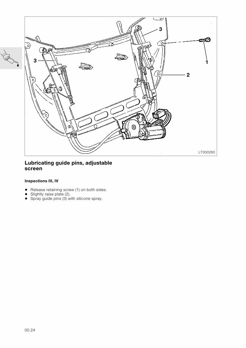
Lubricating guide pins, adjustable screen
Inspections III, IV
• Release retaining screw (1) on both sides.• Slightly raise plate (2).• Spray guide pins (3) with silicone spray.
LT000260
2
13
3
00.24
Checking idle speed, synchronising and CO value and adjusting if nec-essary
Inspections I, II, III, IV
L Note:The basic settings (ignition, valve clearance) must be correct.
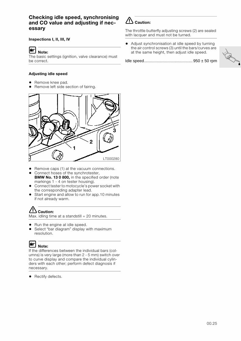
Adjusting idle speed
• Remove knee pad.• Remove left side section of fairing.
• Remove caps (1) at the vacuum connections.• Connect hoses of the synchrotester,
BMW No. 13 0 800, in the specified order (note markings 1 - 4 on tester housing).
• Connect tester to motocycle’s power socket with the corresponding adapter lead.
• Start engine and allow to run for app.10 minutes if not already warm.
e Caution:Max. idling time at a standstill = 20 minutes.
• Run the engine at idle speed.• Select “bar diagram” display with maximum
resolution.
L Note:If the differences between the individual bars (col-umns) is very large (more than 2 - 5 mm) switch over to curve display and compare the individual cylin-ders with each other; perform defect diagnosis if necessary.
• Rectify defects.
e Caution:
The throttle butterfly adjusting screws (2) are sealed with lacquer and must not be turned.
• Adjust synchronisation at idle speed by turning the air control screws (3) until the bars/curves are at the same height, then adjust idle speed.
Idle speed........................................... 950 ± 50 rpm
LT000280
3
12
00.25
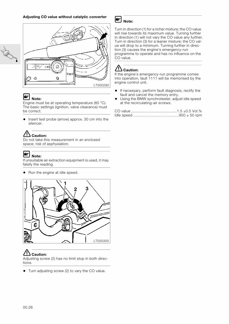
Adjusting CO value without catalytic converter
L Note:Engine must be at operating temperature (85 °C).The basic settings (ignition, valve clearance) must be correct.
• Insert test probe (arrow) approx. 30 cm into the silencer.
e Caution:Do not take this measurement in an enclosed space; risk of asphyxiation.
L Note:If unsuitable air extraction equipment is used, it may falsify the reading.
• Run the engine at idle speed.
e Caution:Adjusting screw (2) has no limit stop in both direc-tions.
• Turn adjusting screw (2) to vary the CO value.
L Note:
Turn in direction (1) for a richer mixture; the CO value will rise towards its maximum value. Turning further in direction (1) will not vary the CO value any further. Turn in direction (3) for a leaner mixture; the CO val-ue will drop to a minimum. Turning further in direc-tion (3) causes the engine’s emergency-run programme to operate and has no influence on the CO value.
e Caution:If the engine’s emergency-run programme comes into operation, fault 1111 will be memorised by the engine control unit.
• If necessary, perform fault diagnosis, rectify the fault and cancel the memory entry.
• Using the BMW synchrotester, adjust idle speed at the recirculating-air screws.
CO value ..........................................1.5 ±0.5 Vol.%Idle speed ..........................................950 ± 50 rpm
LT000290
LT000300
12 3
00.26
11
Contents Page
11 Motor
Technical data ................................................................................................................................5
Removing engine ........................................................................................................................11
Dismantling engine ....................................................................................................................12
Removing intermediate flange .................................................................................................13Removing driver ................................................................................................................................13Removing clutch housing ..................................................................................................................14
Stripping down and re-assembling intermediate flange ..............................................15Removing the driver bearing ..............................................................................................................15Installing driver bearing .....................................................................................................................15Removing and installing shaft sealing ring for driver ..........................................................................16
Removing countershaft and layshaft with freewheel .....................................................16
Dismantling and assembling freewheel ...............................................................................17Stripping down freewheel ..................................................................................................................17Assembling freewheel .......................................................................................................................17
Removing and installing layshaft needle roller bearing ................................................18Removing bearing .............................................................................................................................18Installing bearing ...............................................................................................................................18
Removing timing chain cover ..................................................................................................19Removing the Hall-effect signal transmitter .......................................................................................19Remove the crankshaft cover ............................................................................................................19Removing cylinder head cover ..........................................................................................................19Removing and installing sealing ring in timing case cover .................................................................19
Removing the timing chain .......................................................................................................20Removing chain tensioner .................................................................................................................20Removing chain tensioner rail ...........................................................................................................20Renewing chain tensioner rail facing .................................................................................................20Removing camshaft chain sprockets .................................................................................................21Removing chain guide .......................................................................................................................21
Removing, stripping down and assembling cylinder head .........................................22Removing camshafts .........................................................................................................................22Removing cylinder head ....................................................................................................................22Removing bucket-type tappets .........................................................................................................22Removing valves ...............................................................................................................................23Remachining valve seat .....................................................................................................................23Installing valve and valve stem seal ...................................................................................................24
Removing crankshaft ...................................................................................................................25Removing big end bearings ...............................................................................................................25Removing main bearings ...................................................................................................................25
11.1
Contents Page
Removing pistons with conrods, stripping down and re-assembling ...................26Removing piston with conrod ............................................................................................................26Dismantling piston .............................................................................................................................26Checking piston dimensions .............................................................................................................26Assembling pistons ...........................................................................................................................27Checking cylinder dimensions ...........................................................................................................27Removing and installing small-end bushing .......................................................................................27Assembling pistons and conrods ......................................................................................................28
Removing and installing crankshaft pinion and rotor flange ......................................28
Removing, dismantling and assembling combined oil-water pump ......................29Removing pump ................................................................................................................................29Dismantling pump .............................................................................................................................29Removing slipring seal and shaft sealing ring ....................................................................................30Removing pressure relief valve ..........................................................................................................30Installing pressure relief valve ............................................................................................................30Install the shaft sealing ring and slipring seal .....................................................................................30Installing pump shaft and impeller .....................................................................................................30
Removing output shaft ...............................................................................................................31Removing oil sump ............................................................................................................................31Removing oil filter ..............................................................................................................................31Removing lower section of crankcase ...............................................................................................31Removing and installing oil level sight glass ......................................................................................31
Stripping and assembling output shaft ...............................................................................32Stripping down output shaft ..............................................................................................................32Stripping down tensioning gear .........................................................................................................32Assembling tensioning gear ..............................................................................................................33Installing damper ...............................................................................................................................33
Assembling engine ....................................................................................................................34
Installing output shaft ..................................................................................................................34Assembling the crankcase ................................................................................................................35Installing oil mesh strainer .................................................................................................................35Installing oil filter ................................................................................................................................35Installing oil sump ..............................................................................................................................35
Measuring crankshaft bearing play .......................................................................................36Measuring radial play ........................................................................................................................36Measuring endplay ............................................................................................................................37
Checking dimensions of crankshaft .....................................................................................37
Installing crankshaft .....................................................................................................................38
Installing piston with conrod ....................................................................................................39
Measuring big end bearing play .............................................................................................40
Installing big end bearing ..........................................................................................................40
Installing combined oil-water pump ......................................................................................41
Installing cylinder head ...............................................................................................................42
Installing camshafts .....................................................................................................................43
11.2
Contents Page
Installing timing chain ..................................................................................................................44
Checking valve clearances .......................................................................................................45
Installing intermediate flange ...................................................................................................46Installing freewheel ............................................................................................................................46Installing countershaft .......................................................................................................................46Installing intermediate flange .............................................................................................................46
Installing driver ...............................................................................................................................46
Installing alternator .......................................................................................................................46
Installing timing case cover ......................................................................................................47
Installing hall-effect transmitter ...............................................................................................47
Installing cover for Hall-effect transmitter ..........................................................................48
Installing cylinder head cover ..................................................................................................49
Installing engine ..........................................................................................................................50
Checking/adjusting valve clearances .............................................................................52
Adjusting valve clearances .......................................................................................................52
11.3

11.4
11
Technical data K 1100 LT K 1100 RS
Engine, general
Engine design Inline four-stroke engine installed longitudinally, with double overhead camshafts, liquid cooling and electronic fuel injection.
Location of engine number At lower rear right of engine block
Cylinder bore mm (in) 70.5 (2.77)
Stroke mm (in) 70 (2.75)
Number of cylinders 4
Effective displacement cc 1093
Compression ratio 11.0 : 1
Power output kW (hp) 74 (100) at 7500 min-1
Max. torque Nm 107 at 5500 min-1
Permissible maximum engine speed min-1 8900
Permissible continuous engine speed min-1 8500
Idle speed min-1 950 +50
Direction of rotation Anti-clockwise. looking at ignition system
Compression test pressure bar (psi)
good above 10.0 (142.3)
normal 8.5…10.0 (120.9...142.3)
poor below 8.5 (120.9)
Engine lubrication Pressurised oil circuit
Oil filter Full-flow type
Difference for opening bypass valve bar (psi) 1.5 (21.3)
Oil pressure warning light comes on below bar (psi) 0.2…0.5 (2.8...7.1)
Pressure relief valve opens at bar (psi) 5.4 (76.8)
Oil content
without filter change l 3.50 (6.2 Imp. pints)
with filter change l 3.75 (6.6 Imp. pints)
Permissible oil consumption l/100km(mile/gal) 0.15 (1,875)
Oil pump Gear-type
11.5
Valves
Valve clearances with engine cold (max. 35 °C)
Inlet valve mm (in) 0.15…0.20 (0.0059…0.0079)
Exhaust valve mm (in) 0.25…0.30 (0.0098…0.0118)
Valve timing at 5/100 mm (0.002 in) preload and3 mm (0.118 in) lift
Inlet opens 14° after TDC
Inlet closes 18° after BDC
Exhaust opens 18° before BDC
Exhaust closes 14° before TDC
Valve length
Inlet mm (in) 115.1 (4.531)
Exhaust mm (in) 113.7 (4.476)
Valve head dia.
Inlet mm (in) 26.45 (1.041)
Exhaust mm (in) 22.95 (0.886)
Stem dia.
Inlet mm (in) 5.96…5.975 (0.2346…0.2352)
Wear limit mm (in) 5.94 (0.2339)
Exhaust mm (in) 5.945…5.96 (0.2341…0.2346)
Wear limit mm (in) 5.925 (0.2333)
Valve head edge thickness
Inlet mm (in) 1.04 (0.041)
Exhaust mm (in) 1.09 (0.043)
Max. valve head runout
Inlet, exhaust mm (in) 0.02 (0.0008)
Valve seat angle
Inlet, exhaust 44° 30’…20’
Valve seat width
Inlet mm (in) 1.1 (0.043) ± 0.15 (0.006)
Wear limit mm (in) 2.5 (0.098)
Exhaust mm (in) 1.3 (0.051) ± 0.15 (0.006)
Wear limit mm (in) 3.0 (0.118)
Length of valve guide
Inlet mm (in) 45 (1.772)
Exhaust mm (in) 57.5 (2.264)
Technical data K 1100 LT K 1100 RS
11.6
Valves
Valve guide dia.
Extl. dia. mm (in) 11.533…11.544 (0.4541…0.4545)
Intl. dia. mm (in) 6.0…6.012 (0.2362…0.2367)
Wear limit mm (in) 6.1 (0.2402)
Bore in cylinder head mm (in) 11.5…11.518 (0.4528…0.4535)
Repair stage mm (in) 11.7…11.718 (0.4606…0.4613)
Valve stem clearance
Inlet mm (in) 0.025…0.052 (0.001…0.002)
Exhaust mm (in) 0.040…0.067 (0.0016…0.0026)
Valve spring
Extl. dia. mm (in) 21.6 (0.8504) ±0.2 (0.0079)
Wire dia. mm (in) 3.2 (0.126)
Spring length, off-load mm (in) 41.1 (1.618)
Wear limit mm (in) 39.6 (1.559)
Winding direction clockwise
Number of effective windings 3.8…6
Total number of windings 7.8
Camshaft
Inlet camshaft ° 284
Exhaust camshaft ° 284
Guide bearing dia. mm (in) 29.970…24.0 (1.180…0.945)
Wear limit mm (in) 29.95 (1.179)
Guide bearing bore mm (in) 30.02…30.041 (1.1819…1.1827)
Camshaft bearing bore mm (in) 24.02…24.041 (0.945…0.9465)
Radial clearance
Guide bearing mm (in) 0.020…0.071 (0.0008…0.0028)
Camshaft bearing mm (in) 0.020…0.071 (0.0008…0.0028)
Cam base circle dia. mm (in) 30 (1.181)
Cam height, inlet and exhaust mm (in) 38.855 (1.5297) ±0.031 (0.0012)
Wear limit mm (in) 38.550 (1.5177)
Tappets
Extl. dia. mm (in) 26.853…26.840 (1.0572…1.0567)
Wear limit mm (in) 25.970 (1.0224)
Bore in cylinder head mm (in) 26.065…26.086 (1.0262…1.0270)
Wear limit mm (in) 26.170 (1.0303)
Radial clearance mm (in) 0.072…0.106 (0.0028…0.0042)
Wear limit mm (in) 0.200 (0.0079)
Timing chain
Single roller chain, endless, pre-stretched, with 126 links
Technical data K 1100 LT K 1100 RS
11.7
Crankshaft
Main bearing and crankpin markings
no colour spot Grinding stage 0
with colour spot Grinding stage 1
Width of guide bearing mm (in) 23.020…23.053 (0.9063…0.9076)
Axial play mm (in) 0.080…0.183 (0.0031…0.0072)
Wear limit mm (in) 0.250 (0.010)
Main bearing dia.Grinding stage 0 mm (in) 44.976…45.000 (1.7707…1.7716)
Grinding stage 1 mm (in) 44.726…44.750 (1.7609…1.7618)
Main bearing radial play mm (in) 0.020…0.056 (0.0008…0.0022)
Wear limit mm (in) 0.130 (0.0051)
Main bearing bore dia. mm (in) 49.00…49.14 (1.929…1.935)
Crankpin dia. Grinding stage 0 mm (in) 37.976…38.000 (1.4951…1.4961)
Grinding stage 1 mm (in) 37.726…37.750 (1.4853…1.4862)
Big end bearing width mm (in) 21.810…22.065 (0.8587…0.8687)
Connecting rod
Small end bore dia. mm (in) 41.000…41.016 (1.6142…1.6148)
Wide big end bearing mm (in) 21.973…22.025 (0.8651…0.8671)
Big end bearing endplay mm (in) 0.130…0.312 (0.0051…0.0123)
Wear limit mm (in) 0.400 (0.0157)
Piston pin bore dia. mm (in) 20.000…20.021 (0.7874…0.7882)
Piston pin bore dia. withbushing mm (in) 18.000…18.021 (0.7087…0.7095)
Distance between centers
up to 1992 model year mm (in) 125.0 (4.9213) ±0.1 (0.0039)
from 1993 model year on mm (in) 131.0 (5.1575) ±0.1 (0.0039)
Permissible weight difference g ± 4
Cylinders
Bore A mm (in) 70.500 (2.7756) ±0.005 (0.0002)
B mm (in) 70.510 (2.7760) ±0.005 (0.0002)
Wear limit mm (in) + 0.05 (0.002)
Pistons
Weight group identification stamped + or -
Piston dia. Make: KS
A mm (in) 70.473 (2.7745) ±0.007 (0.0003)
B mm (in) 70.483 (2.7749) ±0.007 (0.0003)
Direction of installation Arrow on piston crown points forward
Installed clearance mm (in) 0.015…0.039 (0.0006…0.0015)
Wear limit mm (in) 0.130 (0.0051)
Technical data K 1100 LT K 1100 RS
11.8
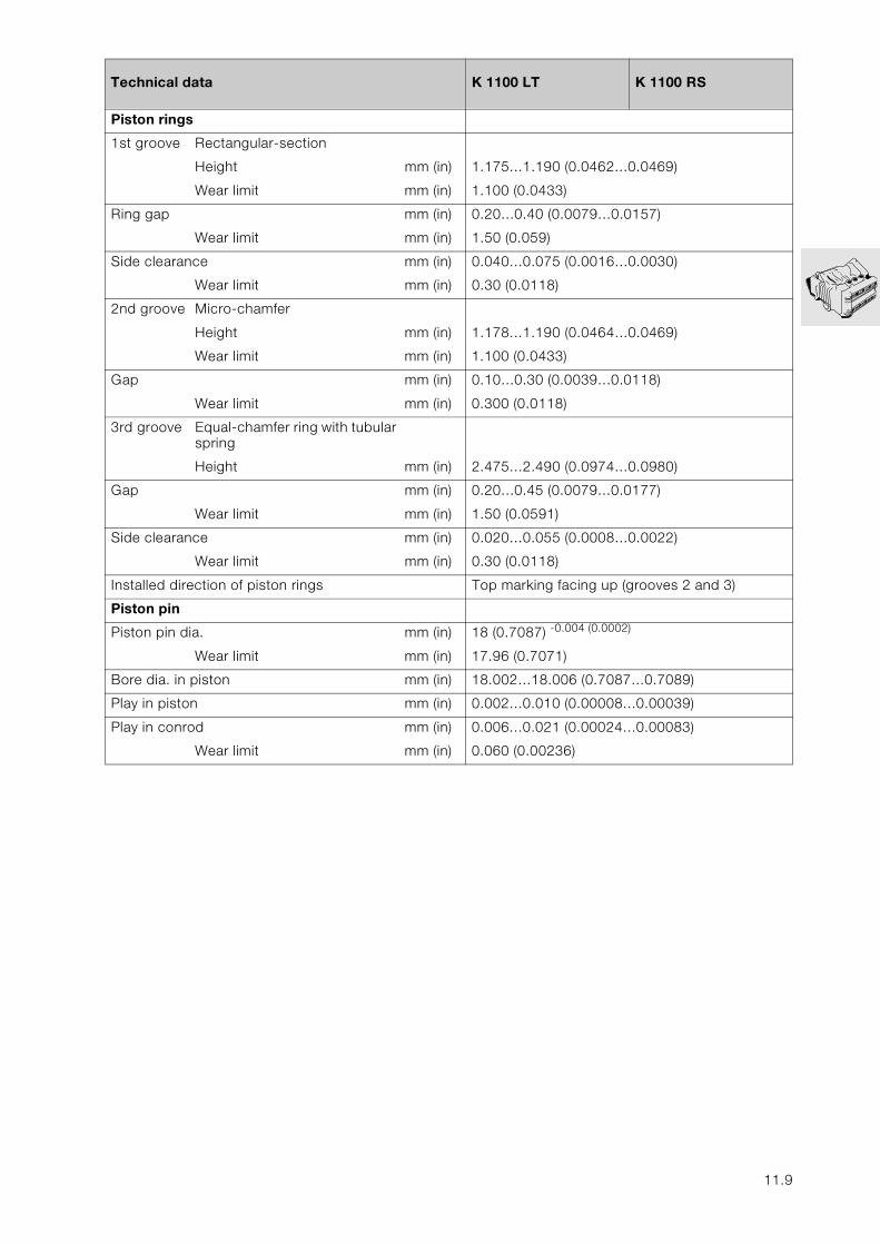
Piston rings
1st groove Rectangular-section
Height mm (in) 1.175…1.190 (0.0462…0.0469)
Wear limit mm (in) 1.100 (0.0433)
Ring gap mm (in) 0.20…0.40 (0.0079…0.0157)
Wear limit mm (in) 1.50 (0.059)
Side clearance mm (in) 0.040…0.075 (0.0016…0.0030)
Wear limit mm (in) 0.30 (0.0118)
2nd groove Micro-chamfer
Height mm (in) 1.178…1.190 (0.0464…0.0469)
Wear limit mm (in) 1.100 (0.0433)
Gap mm (in) 0.10…0.30 (0.0039…0.0118)
Wear limit mm (in) 0.300 (0.0118)
3rd groove Equal-chamfer ring with tubularspring
Height mm (in) 2.475…2.490 (0.0974…0.0980)
Gap mm (in) 0.20…0.45 (0.0079…0.0177)
Wear limit mm (in) 1.50 (0.0591)
Side clearance mm (in) 0.020…0.055 (0.0008…0.0022)
Wear limit mm (in) 0.30 (0.0118)
Installed direction of piston rings Top marking facing up (grooves 2 and 3)
Piston pin
Piston pin dia. mm (in) 18 (0.7087) -0.004 (0.0002)
Wear limit mm (in) 17.96 (0.7071)
Bore dia. in piston mm (in) 18.002…18.006 (0.7087…0.7089)
Play in piston mm (in) 0.002…0.010 (0.00008…0.00039)
Play in conrod mm (in) 0.006…0.021 (0.00024…0.00083)
Wear limit mm (in) 0.060 (0.00236)
Technical data K 1100 LT K 1100 RS
11.9

11.10
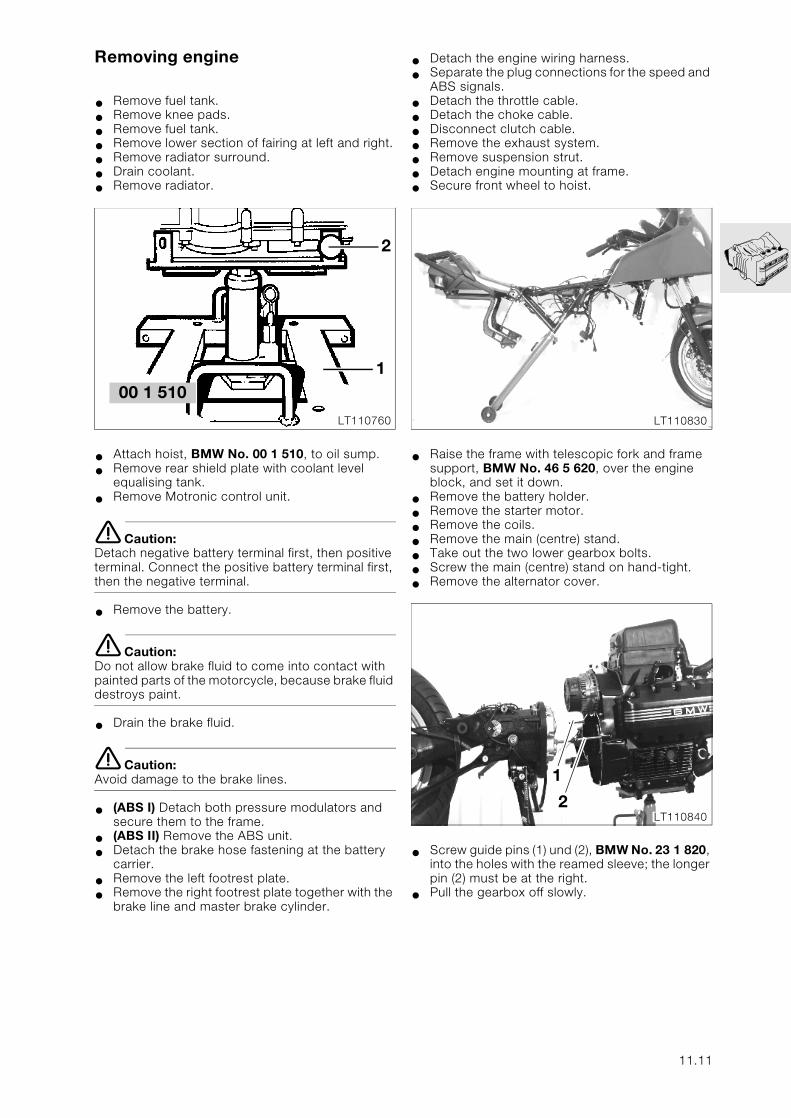
Removing engine
• Remove fuel tank.
• Remove knee pads.
• Remove fuel tank.
• Remove lower section of fairing at left and right.
• Remove radiator surround.
• Drain coolant.
• Remove radiator.
• Attach hoist, BMW No. 00 1 510, to oil sump.
• Remove rear shield plate with coolant level equalising tank.
• Remove Motronic control unit.
e Caution:Detach negative battery terminal first, then positive terminal. Connect the positive battery terminal first, then the negative terminal.
• Remove the battery.
e Caution:Do not allow brake fluid to come into contact with painted parts of the motorcycle, because brake fluid destroys paint.
• Drain the brake fluid.
e Caution:Avoid damage to the brake lines.
• (ABS I) Detach both pressure modulators and secure them to the frame.
• (ABS II) Remove the ABS unit.
• Detach the brake hose fastening at the battery carrier.
• Remove the left footrest plate.
• Remove the right footrest plate together with the brake line and master brake cylinder.
• Detach the engine wiring harness.
• Separate the plug connections for the speed and ABS signals.
• Detach the throttle cable.
• Detach the choke cable.
• Disconnect clutch cable.
• Remove the exhaust system.
• Remove suspension strut.
• Detach engine mounting at frame.
• Secure front wheel to hoist.
• Raise the frame with telescopic fork and frame support, BMW No. 46 5 620, over the engine block, and set it down.
• Remove the battery holder.
• Remove the starter motor.
• Remove the coils.
• Remove the main (centre) stand.
• Take out the two lower gearbox bolts.
• Screw the main (centre) stand on hand-tight.
• Remove the alternator cover.
• Screw guide pins (1) und (2), BMW No. 23 1 820, into the holes with the reamed sleeve; the longer pin (2) must be at the right.
• Pull the gearbox off slowly.
2
1
LT110760
00 1 510
LT110830
1
2LT110840
11.11
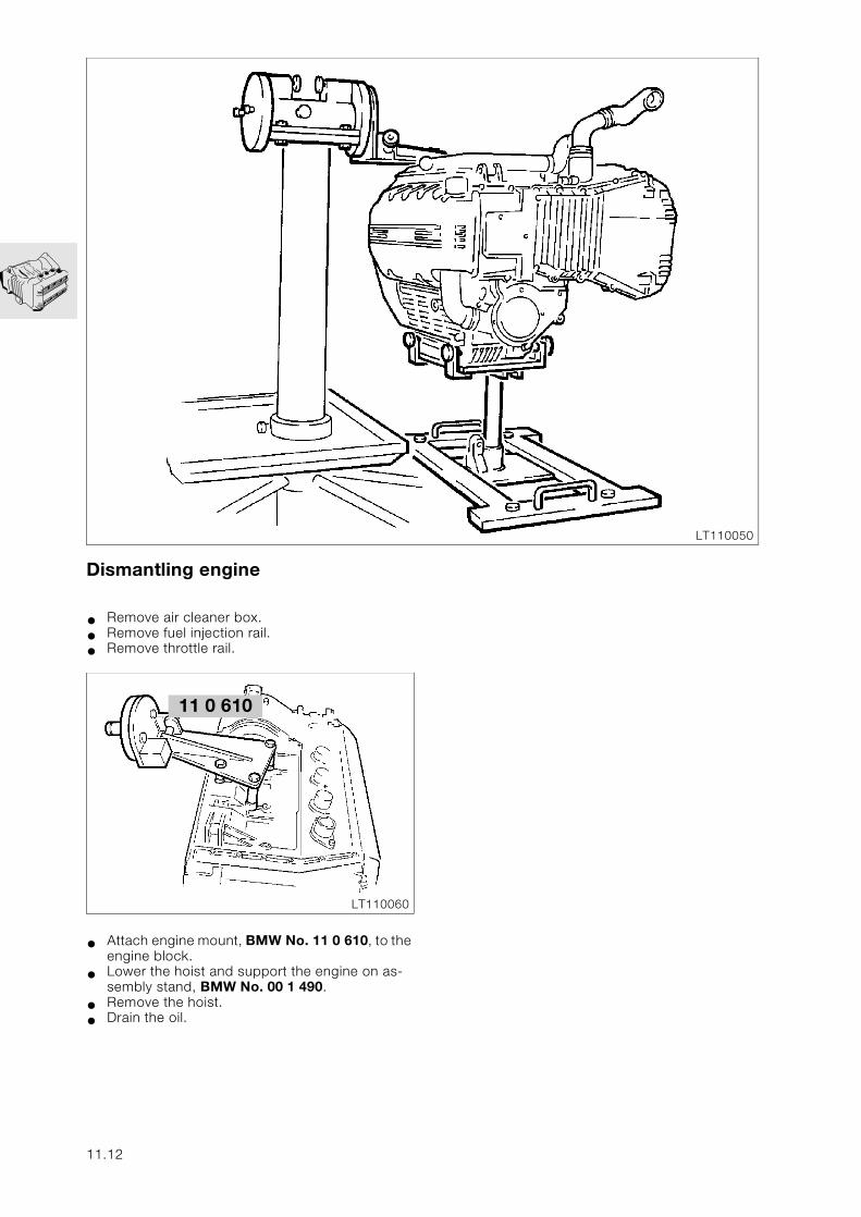
Dismantling engine
• Remove air cleaner box.
• Remove fuel injection rail.
• Remove throttle rail.
• Attach engine mount, BMW No. 11 0 610, to the engine block.
• Lower the hoist and support the engine on as-sembly stand, BMW No. 00 1 490.
• Remove the hoist.
• Drain the oil.
LT110050
LT110060
11 0 610
11.12
LT110070
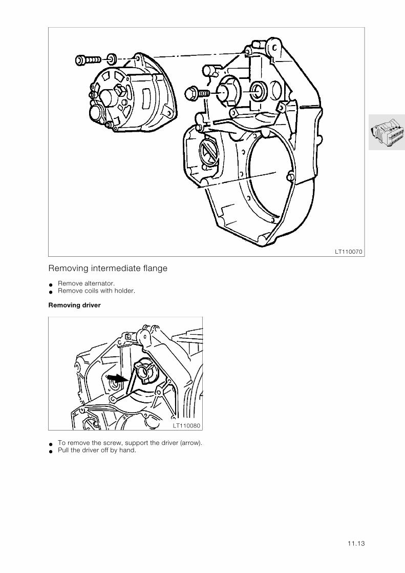
Removing intermediate flange
• Remove alternator.
• Remove coils with holder.
Removing driver
• To remove the screw, support the driver (arrow).
• Pull the driver off by hand.
LT110080
11.13
LT110090
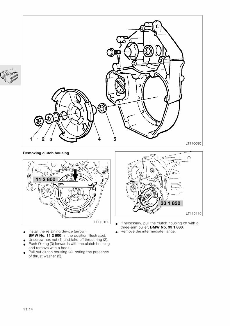
Removing clutch housing
• Install the retaining device (arrow), BMW No. 11 2 800, in the position illustrated.
• Unscrew hex nut (1) and take off thrust ring (2).
• Push O-ring (3) forwards with the clutch housing and remove with a hook.
• Pull out clutch housing (4), noting the presence of thrust washer (5).
1 2 3 4 5
LT110100
11 2 800
11.14
• If necessary, pull the clutch housing off with a three-arm puller, BMW No. 33 1 830.
• Remove the intermediate flange.
LT110110
33 1 830
4 3 2 1
LT110120
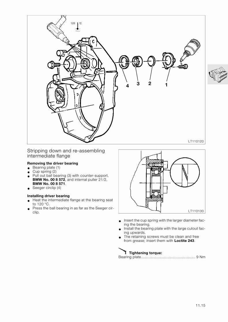
Stripping down and re-assembling intermediate flangeRemoving the driver bearing
• Bearing plate (1)
• Cup spring (2)
• Pull out ball bearing (3) with counter-support, BMW No. 00 8 572, and internal puller 21/2, BMW No. 00 8 571.
• Seeger circlip (4)
Installing driver bearing
• Heat the intermediate flange at the bearing seat to 120 °C.
• Press the ball bearing in as far as the Seeger cir-clip.
j120
• Insert the cup spring with the larger diameter fac-ing the bearing.
• Install the bearing plate with the large cutout fac-ing upwards.
• The retaining screws must be clean and free from grease; insert them with Loctite 243.
X Tightening torque:Bearing plate.................................................. 9 Nm
LT110130
11.15
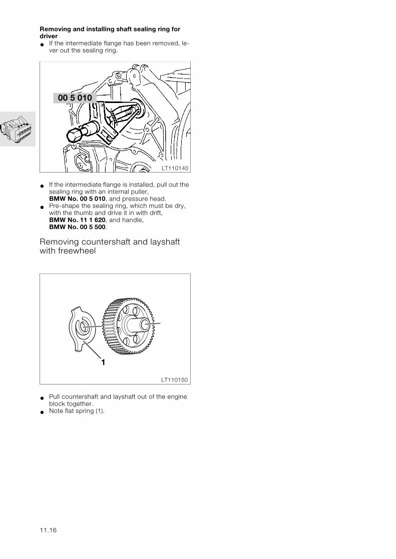
Removing and installing shaft sealing ring for driver
• If the intermediate flange has been removed, le-ver out the sealing ring.
• If the intermediate flange is installed, pull out the sealing ring with an internal puller, BMW No. 00 5 010, and pressure head.
• Pre-shape the sealing ring, which must be dry, with the thumb and drive it in with drift, BMW No. 11 1 620, and handle, BMW No. 00 5 500.
Removing countershaft and layshaft with freewheel
• Pull countershaft and layshaft out of the engine block together.
• Note flat spring (1).
LT110140
00 5 010
1
LT110150
11.16
3
45
LT110160
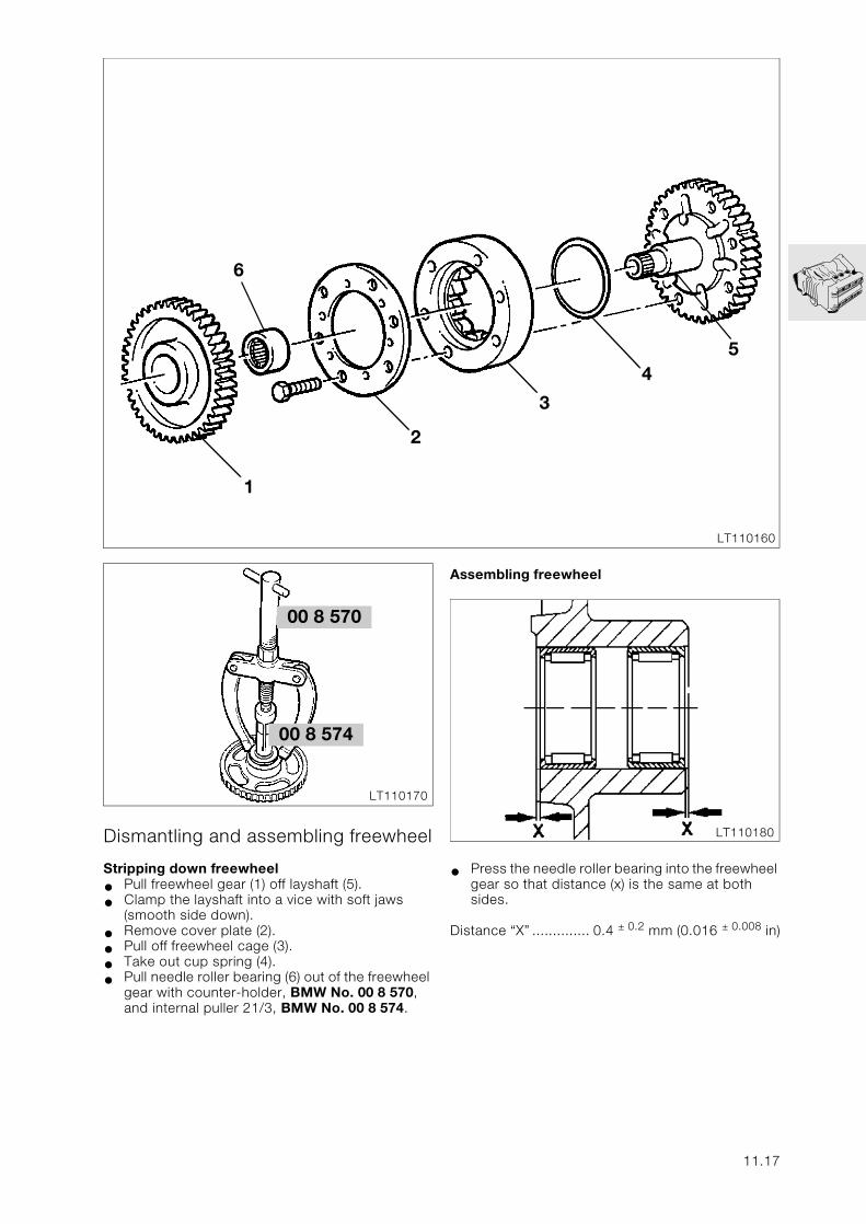
Dismantling and assembling freewheel
Stripping down freewheel
• Pull freewheel gear (1) off layshaft (5).
• Clamp the layshaft into a vice with soft jaws (smooth side down).
• Remove cover plate (2).
• Pull off freewheel cage (3).
• Take out cup spring (4).
• Pull needle roller bearing (6) out of the freewheel gear with counter-holder, BMW No. 00 8 570, and internal puller 21/3, BMW No. 00 8 574.
1
2
6
LT110170
00 8 574
00 8 570
Assembling freewheel
• Press the needle roller bearing into the freewheel gear so that distance (x) is the same at both sides.
Distance “X” .............. 0.4 ± 0.2 mm (0.016 ± 0.008 in)
LT110180
11.17
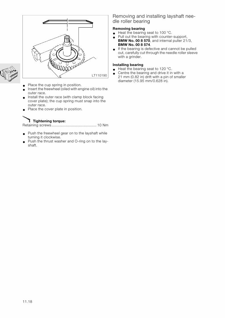
• Place the cup spring in position.
• Insert the freewheel (oiled with engine oil) into the outer race.
• Install the outer race (with clamp block facing cover plate); the cup spring must snap into the outer race.
• Place the cover plate in position.
X Tightening torque:Retaining screws.......................................... 10 Nm
• Push the freewheel gear on to the layshaft while turning it clockwise.
• Push the thrust washer and O-ring on to the lay-shaft.
Removing and installing layshaft nee-dle roller bearing Removing bearing
• Heat the bearing seat to 100 °C.
• Pull out the bearing with counter-support, BMW No. 00 8 570, and internal puller 21/3, BMW No. 00 8 574.
• If the bearing is defective and cannot be pulled out, carefully cut through the needle roller sleeve with a grinder.
Installing bearing
• Heat the bearing seat to 120 °C.
• Centre the bearing and drive it in with a21 mm (0.82 in) drift with a pin of smaller diameter (15.95 mm/0.628 in).
LT110190
11.18
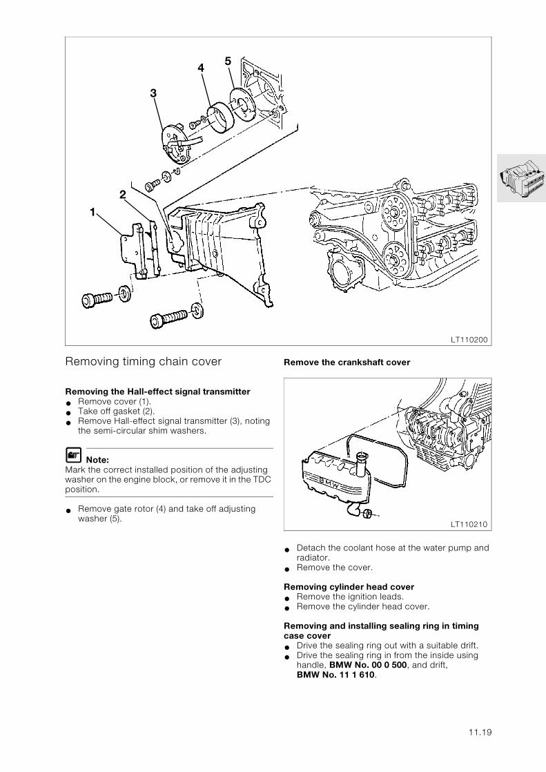
Removing timing chain cover
Removing the Hall-effect signal transmitter
• Remove cover (1).
• Take off gasket (2).
• Remove Hall-effect signal transmitter (3), noting the semi-circular shim washers.
L Note:Mark the correct installed position of the adjusting washer on the engine block, or remove it in the TDC position.
• Remove gate rotor (4) and take off adjusting washer (5).
Remove the crankshaft cover
• Detach the coolant hose at the water pump and radiator.
• Remove the cover.
Removing cylinder head cover
• Remove the ignition leads.
• Remove the cylinder head cover.
Removing and installing sealing ring in timing case cover
• Drive the sealing ring out with a suitable drift.
• Drive the sealing ring in from the inside using handle, BMW No. 00 0 500, and drift, BMW No. 11 1 610.
1
2
3
4 5
LT110200
LT110210
11.19
3 2
4
LT110230
11 5 500
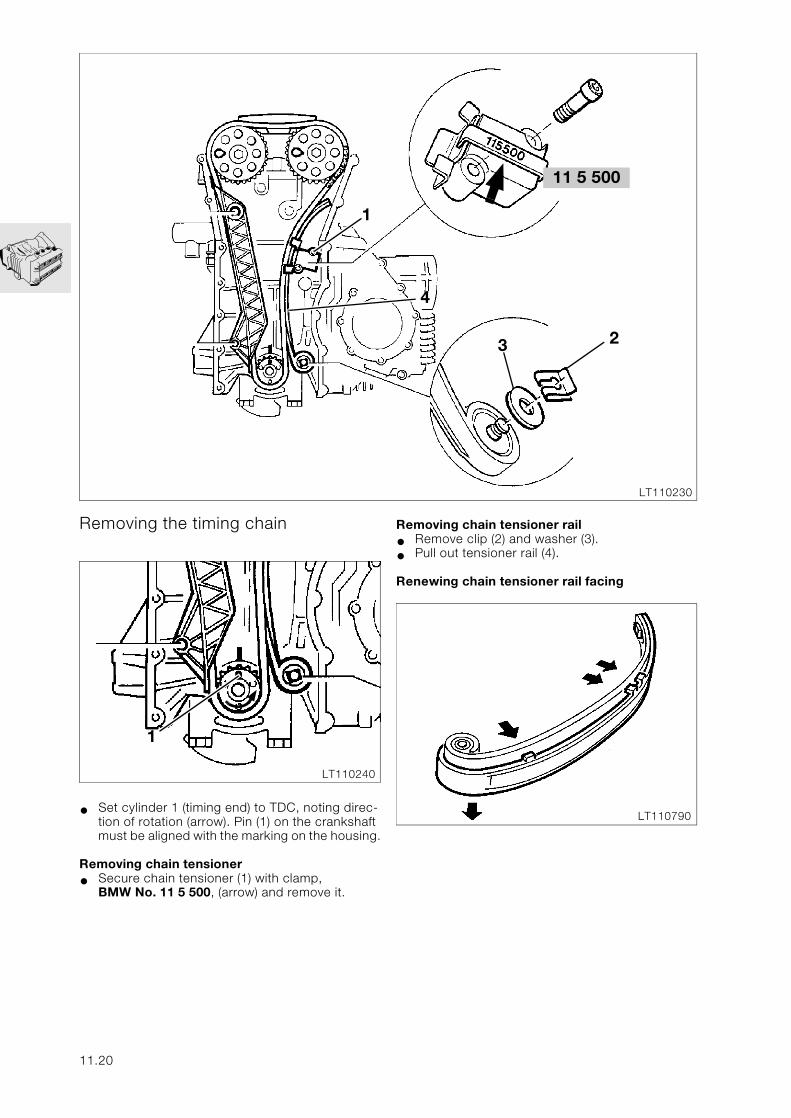
Removing the timing chain
• Set cylinder 1 (timing end) to TDC, noting direc-tion of rotation (arrow). Pin (1) on the crankshaft must be aligned with the marking on the housing.
Removing chain tensioner
• Secure chain tensioner (1) with clamp, BMW No. 11 5 500, (arrow) and remove it.
1
1
LT110240
11.20
Removing chain tensioner rail
• Remove clip (2) and washer (3).
• Pull out tensioner rail (4).
Renewing chain tensioner rail facing
LT110790
LT110260
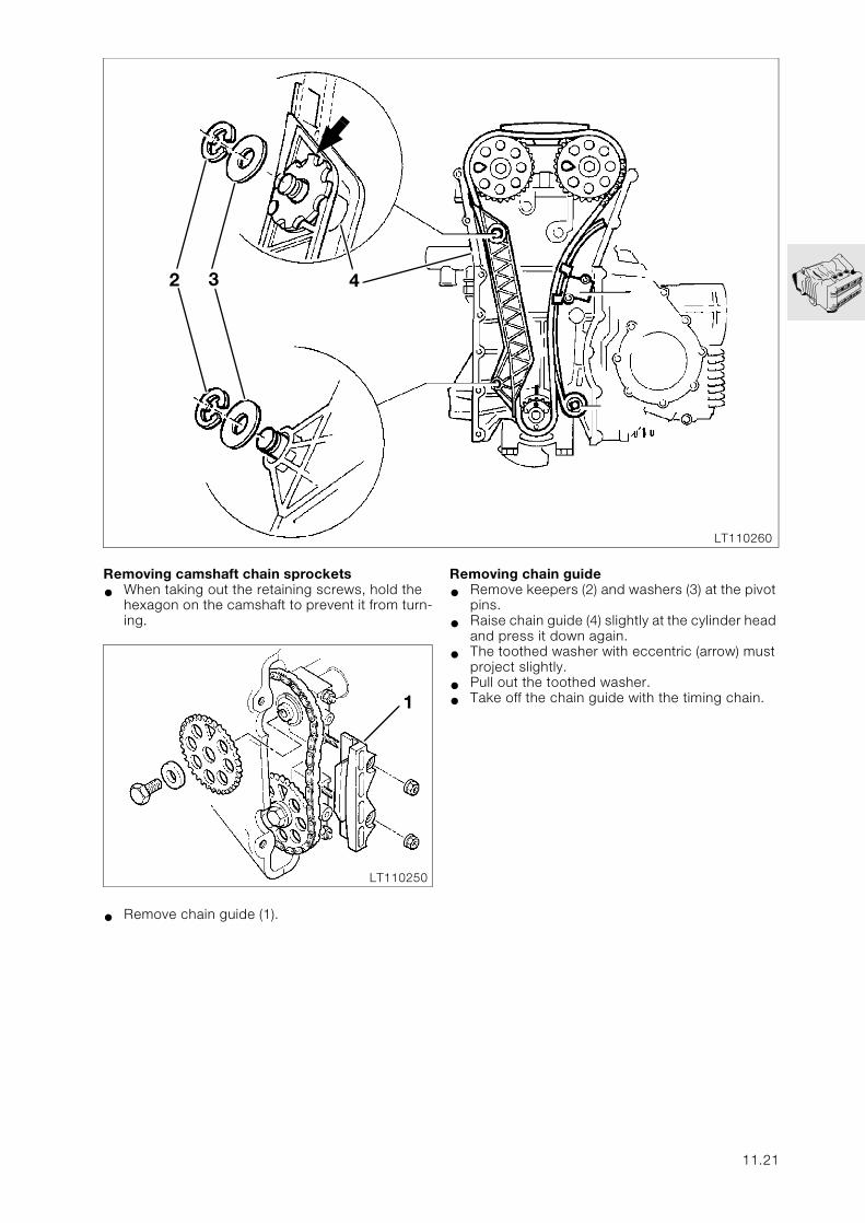
Removing camshaft chain sprockets
• When taking out the retaining screws, hold the hexagon on the camshaft to prevent it from turn-ing.
• Remove chain guide (1).
42 3
1
LT110250
Removing chain guide
• Remove keepers (2) and washers (3) at the pivot pins.
• Raise chain guide (4) slightly at the cylinder head and press it down again.
• The toothed washer with eccentric (arrow) must project slightly.
• Pull out the toothed washer.
• Take off the chain guide with the timing chain.
11.21
4
3
1 2
LT110270
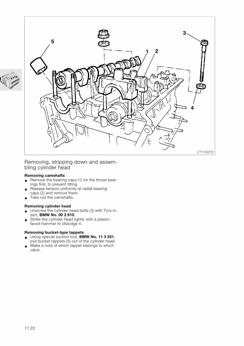
Removing, stripping down and assem-bling cylinder headRemoving camshafts
• Remove the bearing caps (1) for the thrust bear-ings first, to prevent tilting.
• Release tension uniformly at radial bearingcaps (2) and remove them.
• Take out the camshafts.
Removing cylinder head
• Unscrew the cylinder head bolts (3) with Torx in-sert, BMW No. 00 2 610.
• Strike the cylinder head lightly with a plastic-faced hammer to dislodge it.
Removing bucket-type tappets
• Using special suction tool, BMW No. 11 3 251, pull bucket tappets (5) out of the cylinder head.
• Make a note of which tappet belongs to which valve.
5
11.22
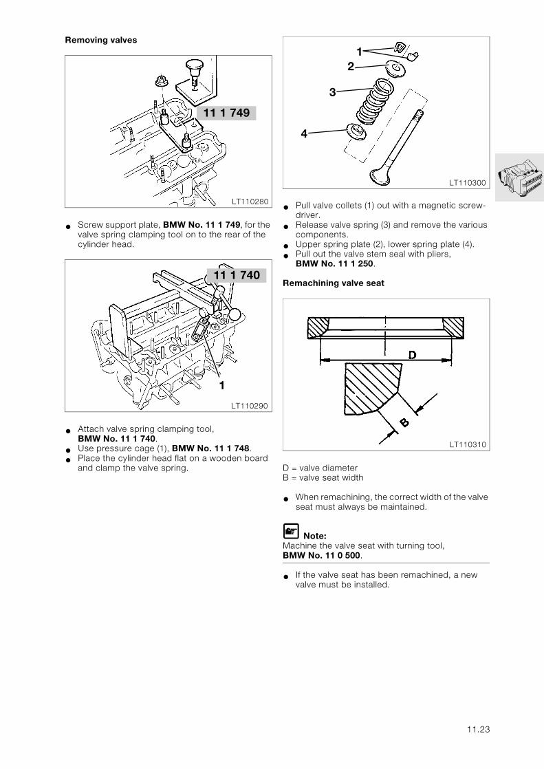
Removing valves
• Screw support plate, BMW No. 11 1 749, for the valve spring clamping tool on to the rear of the cylinder head.
• Attach valve spring clamping tool, BMW No. 11 1 740.
• Use pressure cage (1), BMW No. 11 1 748.
• Place the cylinder head flat on a wooden board and clamp the valve spring.
• Pull valve collets (1) out with a magnetic screw-driver.
• Release valve spring (3) and remove the various components.
• Upper spring plate (2), lower spring plate (4).
• Pull out the valve stem seal with pliers, BMW No. 11 1 250.
Remachining valve seat
D = valve diameterB = valve seat width
• When remachining, the correct width of the valve seat must always be maintained.
L Note:Machine the valve seat with turning tool, BMW No. 11 0 500.
• If the valve seat has been remachined, a new valve must be installed.
LT110280
11 1 749
1
LT110290
11 1 740
21
3
4
LT110300
LT110310
11.23
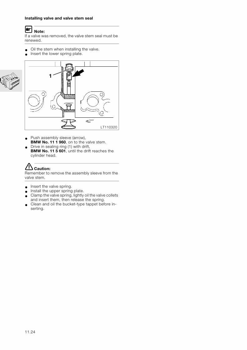
Installing valve and valve stem seal
L Note:If a valve was removed, the valve stem seal must be renewed.
• Oil the stem when installing the valve.
• Insert the lower spring plate.
• Push assembly sleeve (arrow), BMW No. 11 1 960, on to the valve stem.
• Drive in sealing ring (1) with drift, BMW No. 11 5 601, until the drift reaches the cylinder head.
e Caution:Remember to remove the assembly sleeve from the valve stem.
• Insert the valve spring.
• Install the upper spring plate.
• Clamp the valve spring, lightly oil the valve collets and insert them, then release the spring.
• Clean and oil the bucket-type tappet before in-serting.
1
LT110320
11.24
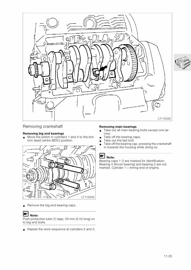
Removing crankshaft
Removing big end bearings
• Move the piston in cylinders 1 and 4 to the bot-tom dead centre (BDC) position.
• Remove the big end bearing caps.
L Note:Push protective tube (1) (app. 50 mm (2 in) long) on to big end bolts.
• Repeat the work sequence at cylinders 2 and 3.
Removing main bearings
• Take out all main bearing bolts except one (ar-row).
• Take off the bearing caps.
• Take out the last bolt.
• Take off the bearing cap, pressing the crankshaft in towards the housing while doing so.
L Note:Bearing caps 1-3 are marked for identification. Bearing 4 (thrust bearing) and bearing 5 are not marked. Cylinder 1 = timing end of engine.
LT110330
1
LT110340
11.25
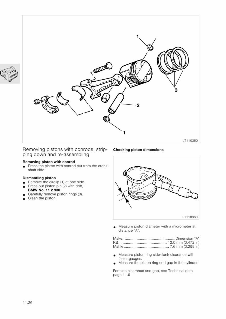
1
3
1
2
LT110350
Removing pistons with conrods, strip-ping down and re-assemblingRemoving piston with conrod
• Press the piston with conrod out from the crank-shaft side.
Dismantling piston
• Remove the circlip (1) at one side.
• Press out piston pin (2) with drift, BMW No. 11 2 930.
• Carefully remove piston rings (3).
• Clean the piston.
11.26
Checking piston dimensions
• Measure piston diameter with a micrometer at distance “A”.
Make: ...............................................Dimension “A”KS............................................. 12.0 mm (0.472 in)Mahle .......................................... 7.6 mm (0.299 in)
• Measure piston ring side-flank clearance with feeler gauges.
• Measure the piston ring end gap in the cylinder.
For side clearance and gap, see Technical data page 11.9
A
LT110360
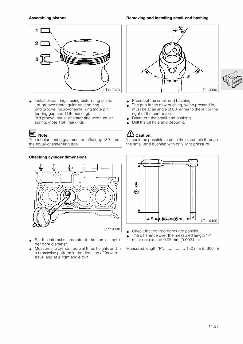
Assembling pistons
• Install piston rings, using piston-ring pliers.1st groove: rectangular-section ring2nd groove: micro-chamfer ring (note pinfor ring gap and TOP marking).3rd groove: equal-chamfer ring with tubularspring, (note TOP marking).
L Note:The tubular spring gap must be offset by 180° from the equal-chamfer ring gap.
Checking cylinder dimensions
• Set the internal micrometer to the nominal cylin-der bore diameter.
• Measure the cylinder bore at three heights and in a crosswise pattern: in the direction of forward travel and at a right angle to it.
Removing and installing small-end bushing
• Press out the small-end bushing.
• The gap in the new bushing, when pressed in, must be at an angle of 60° either to the left or the right of the centre axis.
• Ream out the small-end bushing.
• Drill the oil hole and deburr it.
e Caution:It should be possible to push the piston pin through the small-end bushing with only light pressure.
• Check that conrod bores are parallel.
• The difference over the measured length “P” must not exceed 0.06 mm (0.0024 in).
Measured length “P”................... 150 mm (5.906 in)
1
2
3
LT110370
LT110380
30°
60° 60°
LT110390
LT110400
11.27
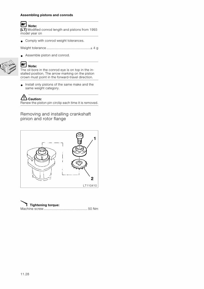
Assembling pistons and conrods
L Note:[LT] Modified conrod length and pistons from 1993 model year on
• Comply with conrod weight tolerances.
Weight tolerance .............................................± 4 g
• Assemble piston and conrod.
L Note:The oil bore in the conrod eye is on top in the in-stalled position. The arrow marking on the piston crown must point in the forward-travel direction.
• Install only pistons of the same make and the same weight category.
e Caution:Renew the piston pin circlip each time it is removed.
Removing and installing crankshaft pinion and rotor flange
X Tightening torque:Machine screw............................................. 50 Nm
1
2LT110410
11.28
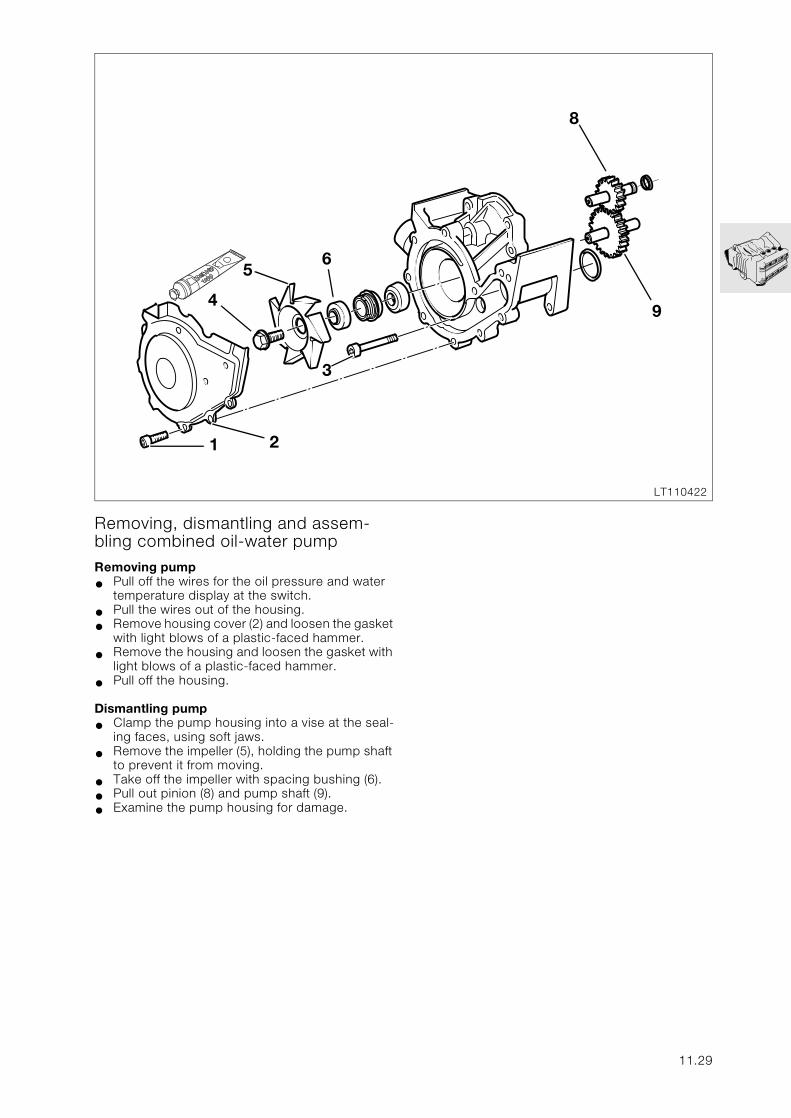
Removing, dismantling and assem-bling combined oil-water pumpRemoving pump
• Pull off the wires for the oil pressure and water temperature display at the switch.
• Pull the wires out of the housing.
• Remove housing cover (2) and loosen the gasket with light blows of a plastic-faced hammer.
• Remove the housing and loosen the gasket with light blows of a plastic-faced hammer.
• Pull off the housing.
Dismantling pump
• Clamp the pump housing into a vise at the seal-ing faces, using soft jaws.
• Remove the impeller (5), holding the pump shaft to prevent it from moving.
• Take off the impeller with spacing bushing (6).
• Pull out pinion (8) and pump shaft (9).
• Examine the pump housing for damage.
3
4
56
8
9
1 2
LT110422
11.29
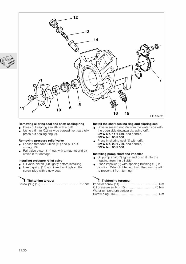
7
14
1516LT110432
Removing slipring seal and shaft sealing ring
• Press out slipring seal (6) with a drift.
• Using a 5 mm (0.2 in) wide screwdriver, carefully press out sealing ring (5).
Removing pressure relief valve
• Loosen threaded union (12) and pull outspring (13).
• Pull valve piston (14) out with a magnet and ex-amine it for damage.
Installing pressure relief valve
• Oil valve piston (14) lightly before installing.
• Insert spring (13) and insert and tighten the screw plug with a new seal.
X Tightening torque:Screw plug (12) ............................................ 27 Nm
911 10
12
13
65
11.30
Install the shaft sealing ring and slipring seal
• Drive in sealing ring (5) from the water side with the open side downwards, using drift, BMW No. 11 1 640, and handle, BMW No. 00 5 500.
• Press in slipring seal (6) with drift,BMW No. 23 1 780, and handle, BMW No. 00 5 500.
Installing pump shaft and impeller
• Oil pump shaft (7) lightly and push it into the housing from the oil side.
• Place impeller (9) with spacing bushing (10) in position. When tightening, hold the pump shaft to prevent it from turning.
X Tightening torques:Impeller screw (11) ....................................... 33 NmOil pressure switch (15)................................ 40 NmWater temperature sensor orScrew plug (16) .............................................. 9 Nm
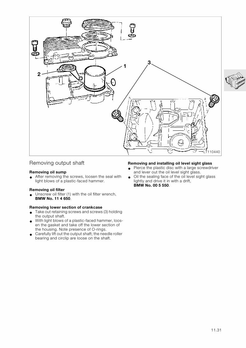
LT110440
3
Removing output shaft
Removing oil sump
• After removing the screws, loosen the seal with light blows of a plastic-faced hammer.
Removing oil filter
• Unscrew oil filter (1) with the oil filter wrench, BMW No. 11 4 650.
Removing lower section of crankcase
• Take out retaining screws and screws (3) holding the output shaft.
• With light blows of a plastic-faced hammer, loos-en the gasket and take off the lower section of the housing. Note presence of O-rings.
• Carefully lift out the output shaft; the needle roller bearing and circlip are loose on the shaft.
2
1
Removing and installing oil level sight glass
• Pierce the plastic disc with a large screwdriver and lever out the oil level sight glass.
• Oil the sealing face of the oil level sight glass lightly and drive it in with a drift, BMW No. 00 5 550.
11.31
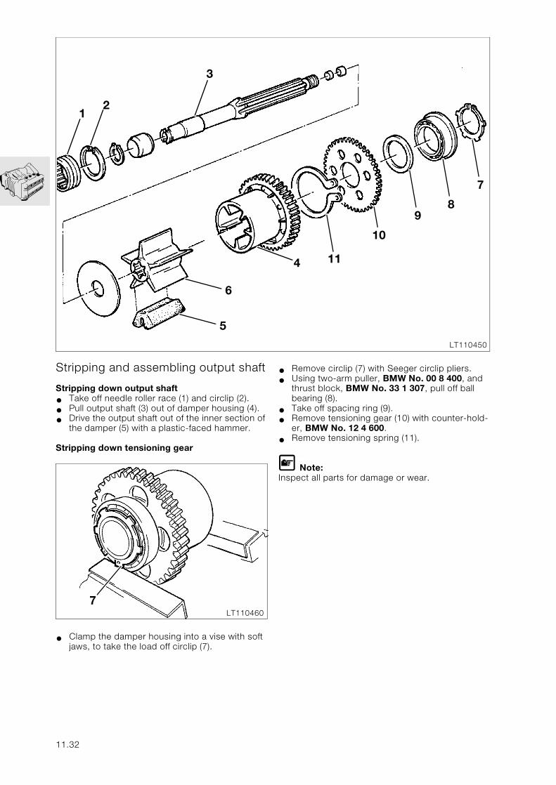
7
89
10
114
LT110450
Stripping and assembling output shaft
Stripping down output shaft
• Take off needle roller race (1) and circlip (2).
• Pull output shaft (3) out of damper housing (4).
• Drive the output shaft out of the inner section of the damper (5) with a plastic-faced hammer.
Stripping down tensioning gear
• Clamp the damper housing into a vise with soft jaws, to take the load off circlip (7).
6
5
12
3
7LT110460
11.32
• Remove circlip (7) with Seeger circlip pliers.
• Using two-arm puller, BMW No. 00 8 400, and thrust block, BMW No. 33 1 307, pull off ball bearing (8).
• Take off spacing ring (9).
• Remove tensioning gear (10) with counter-hold-er, BMW No. 12 4 600.
• Remove tensioning spring (11).
L Note:Inspect all parts for damage or wear.
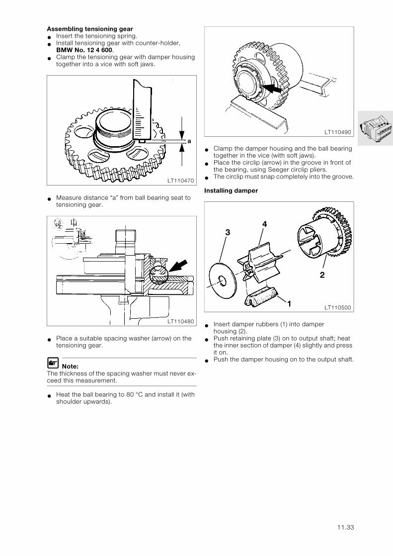
Assembling tensioning gear
• Insert the tensioning spring.
• Install tensioning gear with counter-holder, BMW No. 12 4 600.
• Clamp the tensioning gear with damper housing together into a vice with soft jaws.
• Measure distance “a” from ball bearing seat to tensioning gear.
• Place a suitable spacing washer (arrow) on the tensioning gear.
L Note:The thickness of the spacing washer must never ex-ceed this measurement.
• Heat the ball bearing to 80 °C and install it (with shoulder upwards).
• Clamp the damper housing and the ball bearing together in the vice (with soft jaws).
• Place the circlip (arrow) in the groove in front of the bearing, using Seeger circlip pliers.
• The circlip must snap completely into the groove.
Installing damper
• Insert damper rubbers (1) into damperhousing (2).
• Push retaining plate (3) on to output shaft; heat the inner section of damper (4) slightly and press it on.
• Push the damper housing on to the output shaft.
a
LT110470
LT110480
LT110490
34
2
1 LT110500
11.33
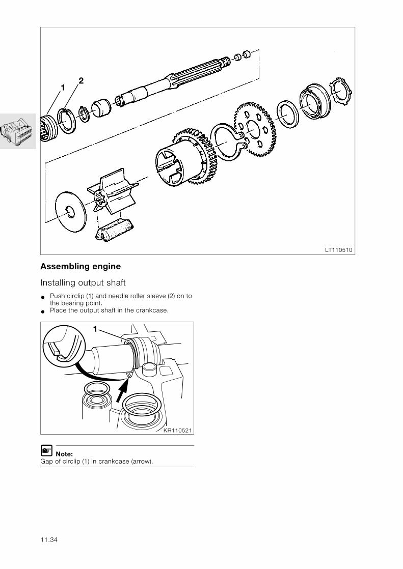
Assembling engine
Installing output shaft
• Push circlip (1) and needle roller sleeve (2) on to the bearing point.
• Place the output shaft in the crankcase.
L Note:Gap of circlip (1) in crankcase (arrow).
12
LT110510
1
KR110521
11.34
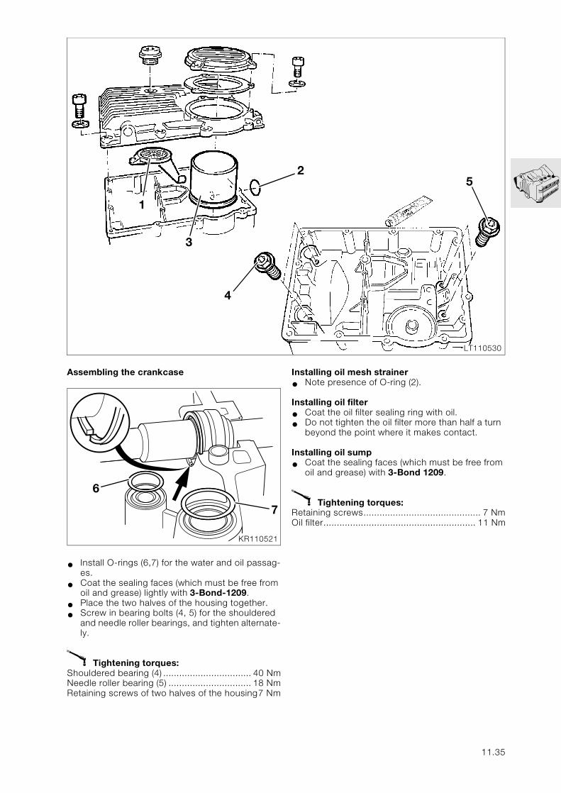
25
LT110530
Assembling the crankcase
• Install O-rings (6,7) for the water and oil passag-es.
• Coat the sealing faces (which must be free from oil and grease) lightly with 3-Bond-1209.
• Place the two halves of the housing together.
• Screw in bearing bolts (4, 5) for the shouldered and needle roller bearings, and tighten alternate-ly.
X Tightening torques:Shouldered bearing (4) ................................. 40 NmNeedle roller bearing (5) ............................... 18 NmRetaining screws of two halves of the housing7 Nm
1
3
4
6
7
KR110521
Installing oil mesh strainer
• Note presence of O-ring (2).
Installing oil filter
• Coat the oil filter sealing ring with oil.
• Do not tighten the oil filter more than half a turn beyond the point where it makes contact.
Installing oil sump
• Coat the sealing faces (which must be free from oil and grease) with 3-Bond 1209.
X Tightening torques:Retaining screws............................................ 7 NmOil filter......................................................... 11 Nm
11.35
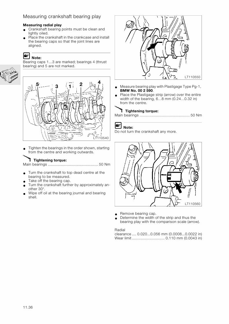
Measuring crankshaft bearing play
Measuring radial play
• Crankshaft bearing points must be clean and lightly oiled.
• Place the crankshaft in the crankcase and install the bearing caps so that the joint lines are aligned.
L Note:Bearing caps 1…3 are marked; bearings 4 (thrust bearing) and 5 are not marked.
• Tighten the bearings in the order shown, starting from the centre and working outwards.
X Tightening torque:Main bearings .............................................. 50 Nm
• Turn the crankshaft to top dead centre at the bearing to be measured.
• Take off the bearing cap.
• Turn the crankshaft further by approximately an-other 30°.
• Wipe off oil at the bearing journal and bearing shell.
• Measure bearing play with Plastigage Type Pg-1, BMW No. 00 2 590.
• Place the Plastigage strip (arrow) over the entire width of the bearing, 6…8 mm (0.24…0.32 in) from the centre.
X Tightening torque:Main bearings .............................................. 50 Nm
L Note:Do not turn the crankshaft any more.
• Remove bearing cap.
• Determine the width of the strip and thus the bearing play with the comparison scale (arrow).
Radialclearance .... 0.020...0.056 mm (0.0008...0.0022 in)Wear limit .............................. 0.110 mm (0.0043 in)
5 3 1 2 4
LT110540
LT110550
LT110560
11.36
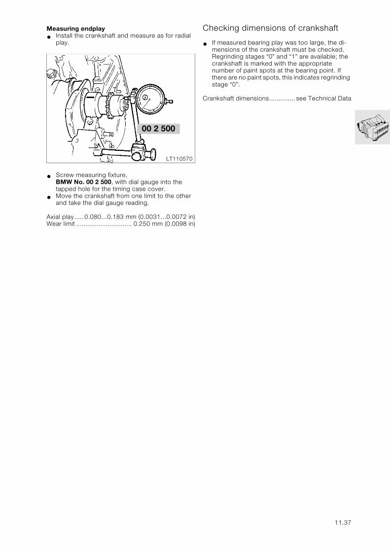
Measuring endplay
• Install the crankshaft and measure as for radial play.
• Screw measuring fixture,BMW No. 00 2 500, with dial gauge into the tapped hole for the timing case cover.
• Move the crankshaft from one limit to the other and take the dial gauge reading.
Axial play.....0.080…0.183 mm (0.0031…0.0072 in)Wear limit .............................. 0.250 mm (0.0098 in)
Checking dimensions of crankshaft
• If measured bearing play was too large, the di-mensions of the crankshaft must be checked.Regrinding stages “0” and “1” are available; the crankshaft is marked with the appropriate number of paint spots at the bearing point. If there are no paint spots, this indicates regrinding stage “0”.
Crankshaft dimensions.............. see Technical Data
LT110570
00 2 500
11.37
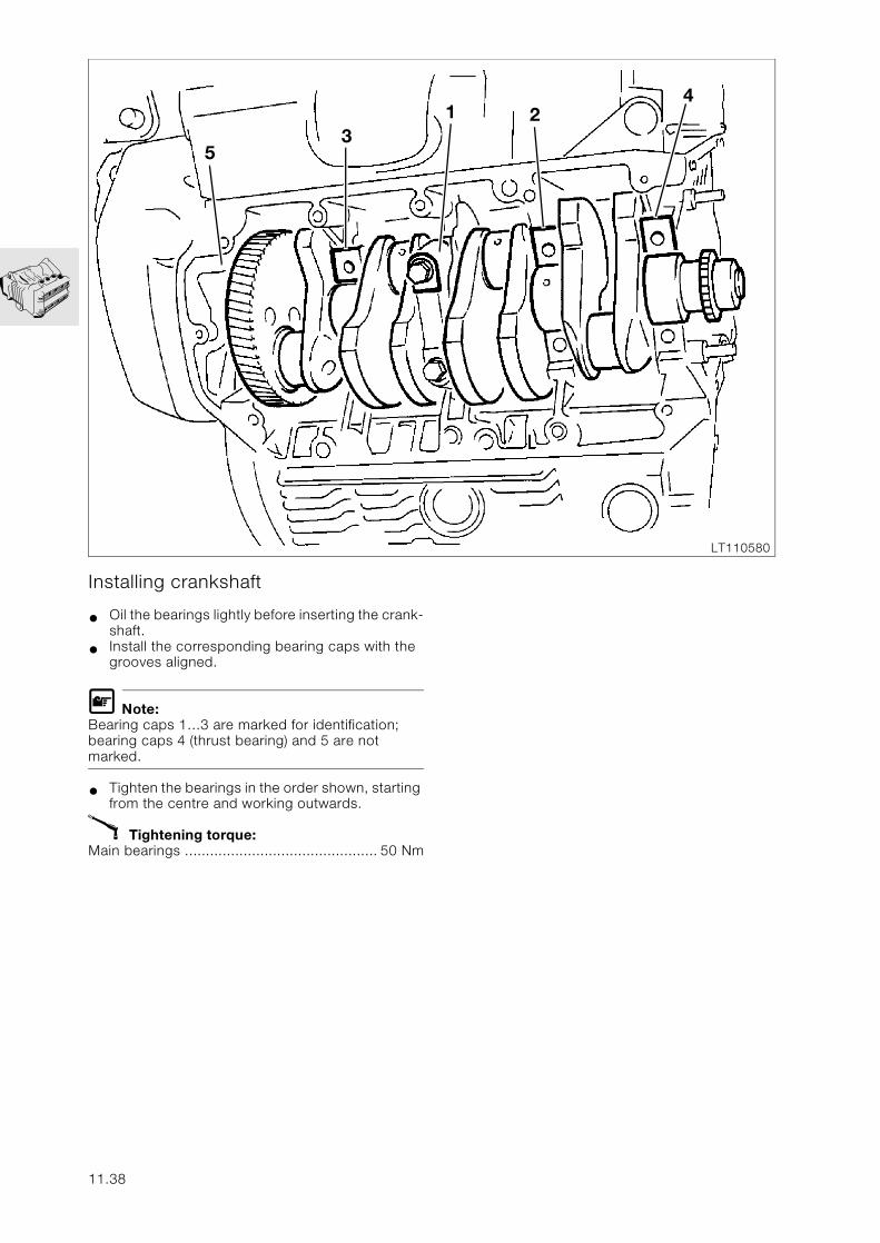
Installing crankshaft
• Oil the bearings lightly before inserting the crank-shaft.
• Install the corresponding bearing caps with the grooves aligned.
L Note:Bearing caps 1…3 are marked for identification; bearing caps 4 (thrust bearing) and 5 are not marked.
• Tighten the bearings in the order shown, starting from the centre and working outwards.
X Tightening torque:Main bearings .............................................. 50 Nm
35
1 24
LT110580
11.38
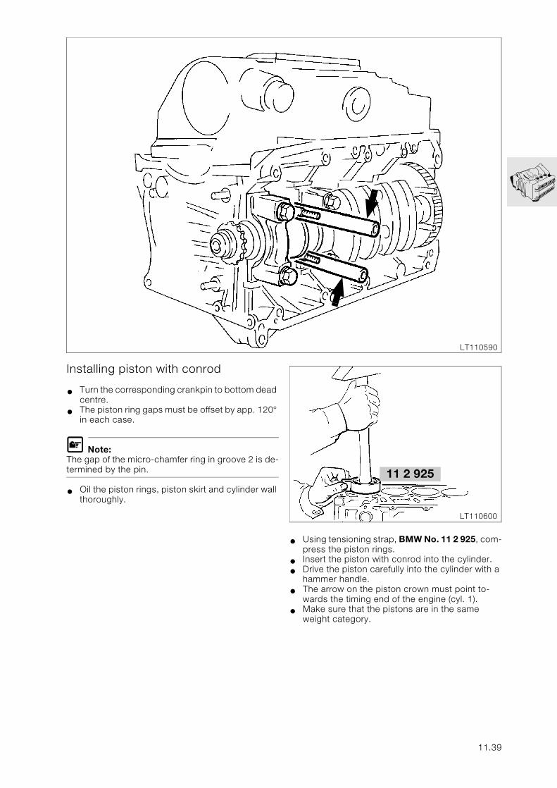
LT110590
Installing piston with conrod
• Turn the corresponding crankpin to bottom dead centre.
• The piston ring gaps must be offset by app. 120° in each case.
L Note:The gap of the micro-chamfer ring in groove 2 is de-termined by the pin.
• Oil the piston rings, piston skirt and cylinder wall thoroughly.
• Using tensioning strap, BMW No. 11 2 925, com-press the piston rings.
• Insert the piston with conrod into the cylinder.
• Drive the piston carefully into the cylinder with a hammer handle.
• The arrow on the piston crown must point to-wards the timing end of the engine (cyl. 1).
• Make sure that the pistons are in the same weight category.
LT110600
11 2 925
11.39
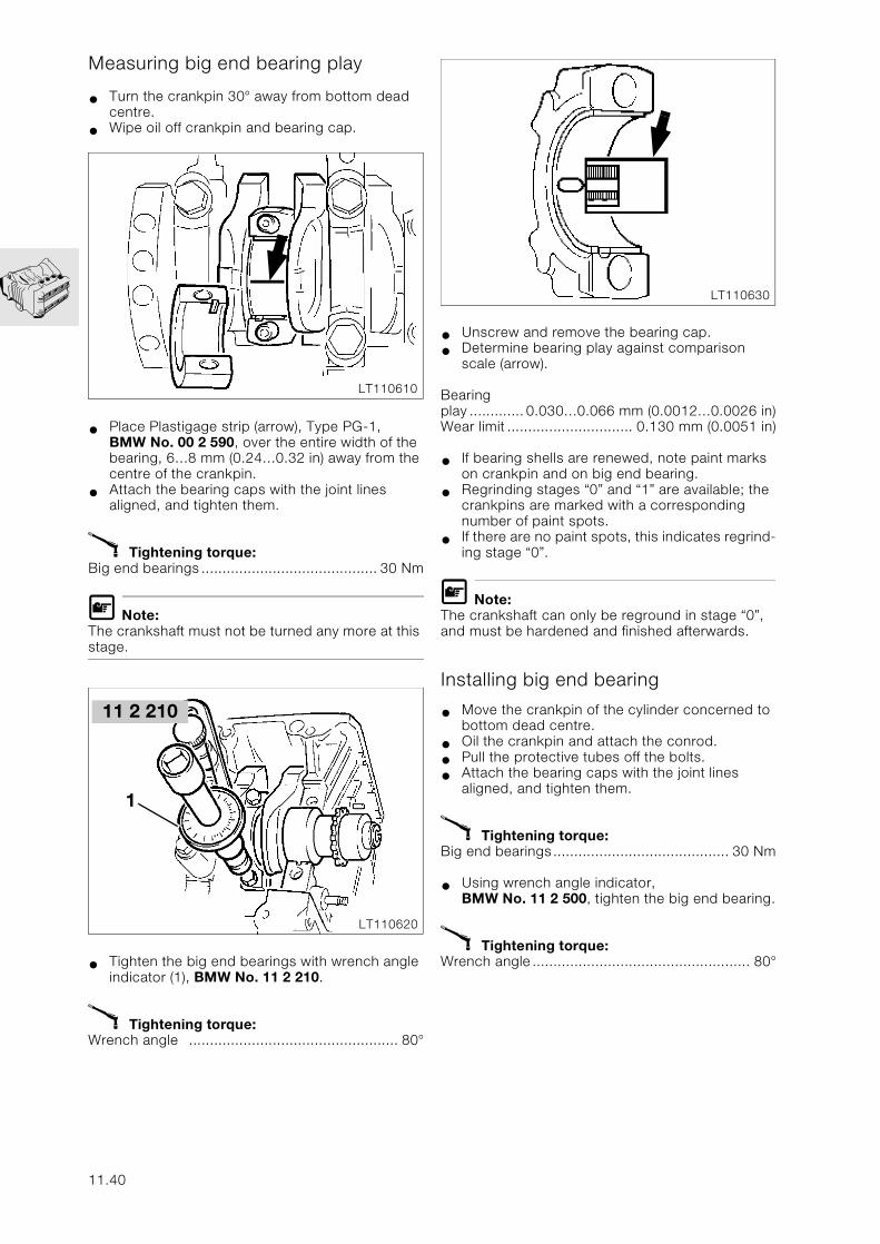
Measuring big end bearing play
• Turn the crankpin 30° away from bottom dead centre.
• Wipe oil off crankpin and bearing cap.
• Place Plastigage strip (arrow), Type PG-1,BMW No. 00 2 590, over the entire width of the bearing, 6…8 mm (0.24…0.32 in) away from the centre of the crankpin.
• Attach the bearing caps with the joint lines aligned, and tighten them.
X Tightening torque:Big end bearings .......................................... 30 Nm
L Note:The crankshaft must not be turned any more at this stage.
• Tighten the big end bearings with wrench angle indicator (1), BMW No. 11 2 210.
X Tightening torque:Wrench angle .................................................. 80°
• Unscrew and remove the bearing cap.
• Determine bearing play against comparison scale (arrow).
Bearingplay ............. 0.030…0.066 mm (0.0012…0.0026 in)Wear limit .............................. 0.130 mm (0.0051 in)
• If bearing shells are renewed, note paint marks on crankpin and on big end bearing.
• Regrinding stages “0” and “1” are available; the crankpins are marked with a corresponding number of paint spots.
• If there are no paint spots, this indicates regrind-ing stage “0”.
L Note:The crankshaft can only be reground in stage “0”, and must be hardened and finished afterwards.
Installing big end bearing
• Move the crankpin of the cylinder concerned to bottom dead centre.
• Oil the crankpin and attach the conrod.
• Pull the protective tubes off the bolts.
• Attach the bearing caps with the joint lines aligned, and tighten them.
X Tightening torque:Big end bearings.......................................... 30 Nm
• Using wrench angle indicator,BMW No. 11 2 500, tighten the big end bearing.
X Tightening torque:Wrench angle .................................................... 80°
LT110610
LT110620
11 2 210
1
LT110630
11.40
Installing combined oil-water pump
• Apply a thin coat of 3-Bond 1209 to the sealing faces, which must be free of oil and grease.
• Place O-ring on water passage.
• Insert the input pinion into the output shaft with an oiled O-ring.
• Attach the pump housing and insert the screws loosely at first.
L Note:Turn the crankshaft several times in order to centre the gearwheels, at the same time gradually tighten-ing the retaining screws.
• Tighten the retaining screws fully.
X Tightening torque:Pump housing to crankcase........................... 7 Nm
• Insert the wire for the oil pressure telltale and temperature display through the housing and connect it.
• Apply a thin coat of 3-Bond to the sealing faces on the cover and housing, which must be free from oil and grease.
• Place the housing cover in position and tighten it.
X Tightening torque:Cover to pump housing.................................. 7 Nm
11.41
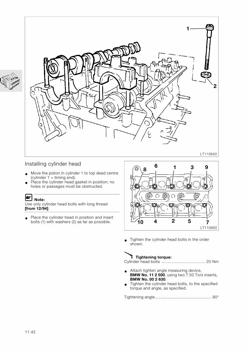
Installing cylinder head
• Move the piston in cylinder 1 to top dead centre (cylinder 1 = timing end).
• Place the cylinder head gasket in position; no holes or passages must be obstructed.
L Note:Use only cylinder head bolts with long thread [from 12/94].
• Place the cylinder head in position and insert bolts (1) with washers (2) as far as possible.
• Tighten the cylinder head bolts in the order shown.
X Tightening torque:Cylinder head bolts ..................................... 20 Nm
• Attach tighten angle measuring device,BMW No. 11 2 500, using two T 50 Torx inserts, BMW No. 00 2 630.
• Tighten the cylinder head bolts, to the specified torque and angle, as specified.
Tightening angle................................................ 90°
1
2
LT110640
1
2
3
4 5
6
7
8 9
10LT110660
11.42
Installing camshafts
L Note:Note correct identification of camshafts.
Inlet side : three grooves after thrust bearingExhaust side: two grooves after thrust bearing
• The camshaft bearing caps are also marked.
Inlet side: odd numbersExhaust side: even numbers
• The numbers increase from the front (timing end) to the rear.
• Oil the camshafts at their bearing points.
• Tighten the bearing caps uniformly, working from the inside outwards.
• Install the thrust bearing (timing end) with chain guide last of all.
X Tightening torque:Bearing cap.................................................... 9 Nm
11.43
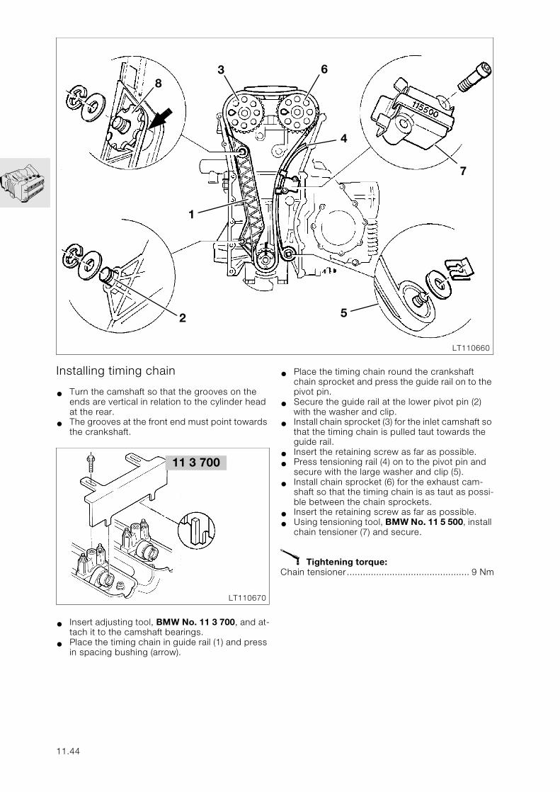
Installing timing chain
• Turn the camshaft so that the grooves on the ends are vertical in relation to the cylinder head at the rear.
• The grooves at the front end must point towards the crankshaft.
• Insert adjusting tool, BMW No. 11 3 700, and at-tach it to the camshaft bearings.
• Place the timing chain in guide rail (1) and press in spacing bushing (arrow).
• Place the timing chain round the crankshaft chain sprocket and press the guide rail on to the pivot pin.
• Secure the guide rail at the lower pivot pin (2) with the washer and clip.
• Install chain sprocket (3) for the inlet camshaft so that the timing chain is pulled taut towards the guide rail.
• Insert the retaining screw as far as possible.
• Press tensioning rail (4) on to the pivot pin and secure with the large washer and clip (5).
• Install chain sprocket (6) for the exhaust cam-shaft so that the timing chain is as taut as possi-ble between the chain sprockets.
• Insert the retaining screw as far as possible.
• Using tensioning tool, BMW No. 11 5 500, install chain tensioner (7) and secure.
X Tightening torque:Chain tensioner.............................................. 9 Nm
1
2
3
4
5
6
7
8
LT110660
LT110670
11 3 700
11.44
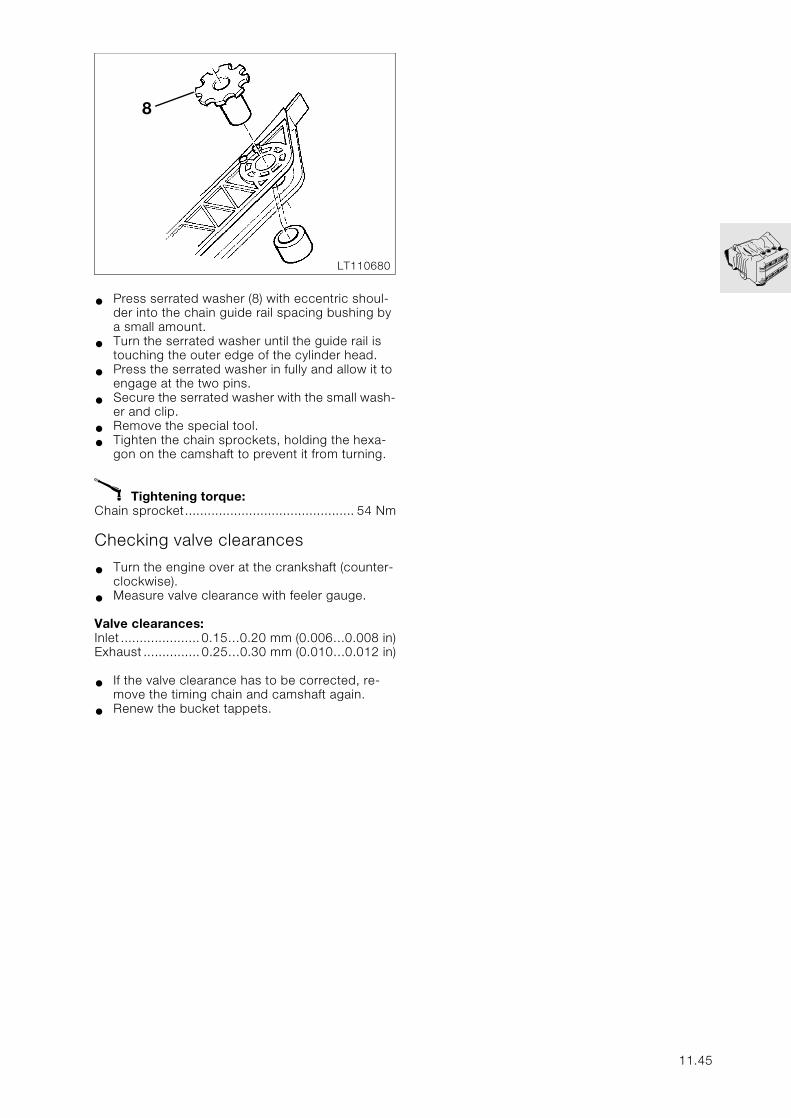
• Press serrated washer (8) with eccentric shoul-der into the chain guide rail spacing bushing by a small amount.
• Turn the serrated washer until the guide rail is touching the outer edge of the cylinder head.
• Press the serrated washer in fully and allow it to engage at the two pins.
• Secure the serrated washer with the small wash-er and clip.
• Remove the special tool.
• Tighten the chain sprockets, holding the hexa-gon on the camshaft to prevent it from turning.
X Tightening torque:Chain sprocket............................................. 54 Nm
Checking valve clearances
• Turn the engine over at the crankshaft (counter-clockwise).
• Measure valve clearance with feeler gauge.
Valve clearances:Inlet .....................0.15…0.20 mm (0.006…0.008 in)Exhaust ...............0.25…0.30 mm (0.010…0.012 in)
• If the valve clearance has to be corrected, re-move the timing chain and camshaft again.
• Renew the bucket tappets.
8
LT110680
11.45
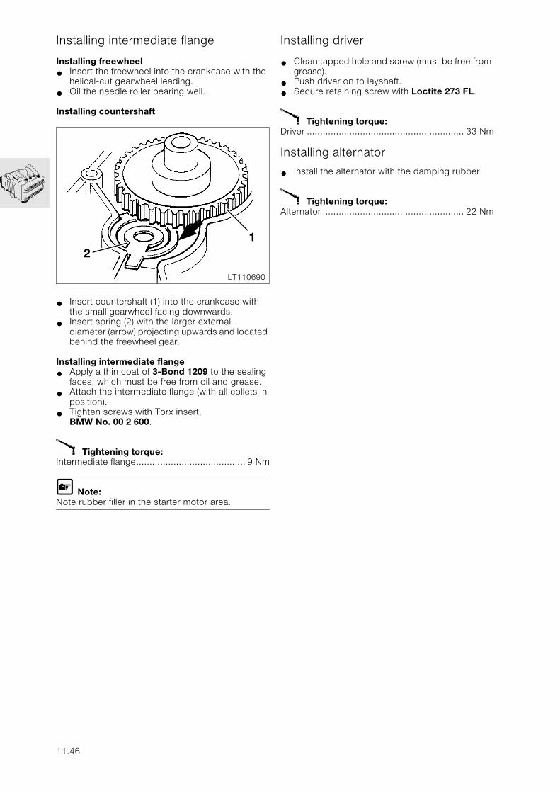
Installing intermediate flange
Installing freewheel
• Insert the freewheel into the crankcase with the helical-cut gearwheel leading.
• Oil the needle roller bearing well.
Installing countershaft
• Insert countershaft (1) into the crankcase with the small gearwheel facing downwards.
• Insert spring (2) with the larger externaldiameter (arrow) projecting upwards and located behind the freewheel gear.
Installing intermediate flange
• Apply a thin coat of 3-Bond 1209 to the sealing faces, which must be free from oil and grease.
• Attach the intermediate flange (with all collets in position).
• Tighten screws with Torx insert, BMW No. 00 2 600.
X Tightening torque:Intermediate flange......................................... 9 Nm
L Note:Note rubber filler in the starter motor area.
Installing driver
• Clean tapped hole and screw (must be free from grease).
• Push driver on to layshaft.
• Secure retaining screw with Loctite 273 FL.
X Tightening torque:Driver ........................................................... 33 Nm
Installing alternator
• Install the alternator with the damping rubber.
X Tightening torque:Alternator ..................................................... 22 Nm
12
LT110690
11.46
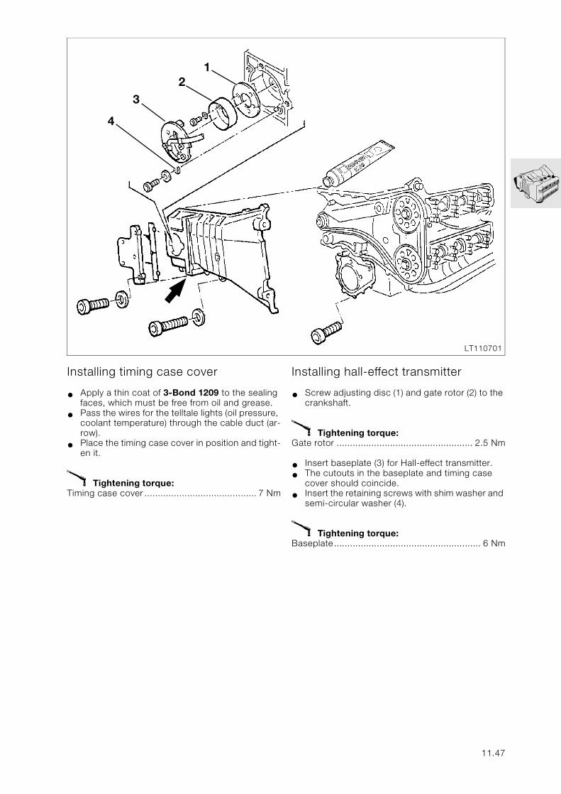
Installing timing case cover
• Apply a thin coat of 3-Bond 1209 to the sealing faces, which must be free from oil and grease.
• Pass the wires for the telltale lights (oil pressure, coolant temperature) through the cable duct (ar-row).
• Place the timing case cover in position and tight-en it.
X Tightening torque:Timing case cover .......................................... 7 Nm
Installing hall-effect transmitter
• Screw adjusting disc (1) and gate rotor (2) to the crankshaft.
X Tightening torque:Gate rotor ................................................... 2.5 Nm
• Insert baseplate (3) for Hall-effect transmitter.
• The cutouts in the baseplate and timing case cover should coincide.
• Insert the retaining screws with shim washer and semi-circular washer (4).
X Tightening torque:Baseplate....................................................... 6 Nm
3
12
4
LT110701
11.47
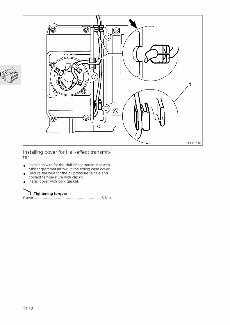
1
LT110710
Installing cover for Hall-effect transmit-ter
• Install the wire for the Hall-effect transmitter with rubber grommet (arrow) in the timing case cover.
• Secure the wire for the oil pressure telltale and coolant temperature with clip (1).
• Install cover with cork gasket.
X Tightening torque:Cover ............................................................. 6 Nm
11.48
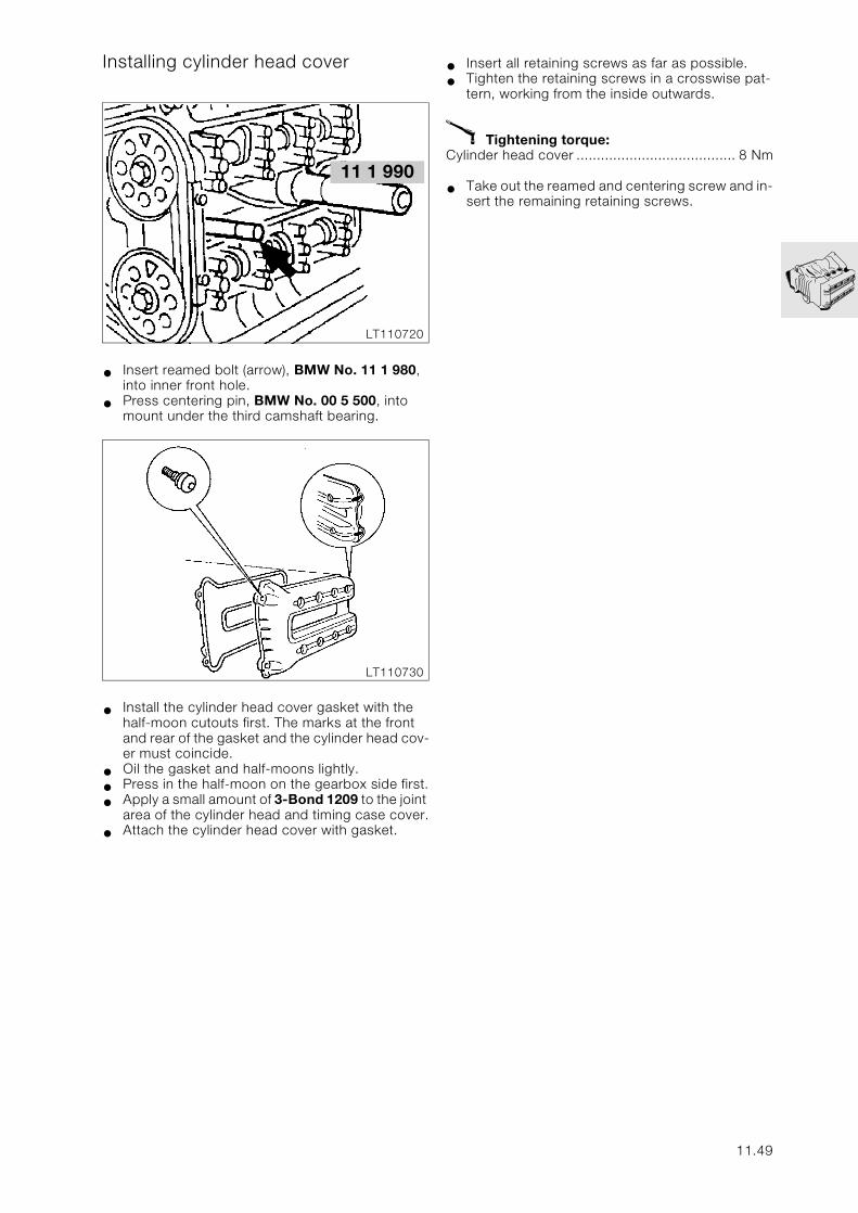
Installing cylinder head cover
• Insert reamed bolt (arrow), BMW No. 11 1 980, into inner front hole.
• Press centering pin, BMW No. 00 5 500, into mount under the third camshaft bearing.
• Install the cylinder head cover gasket with the half-moon cutouts first. The marks at the front and rear of the gasket and the cylinder head cov-er must coincide.
• Oil the gasket and half-moons lightly.
• Press in the half-moon on the gearbox side first.
• Apply a small amount of 3-Bond 1209 to the joint area of the cylinder head and timing case cover.
• Attach the cylinder head cover with gasket.
• Insert all retaining screws as far as possible.
• Tighten the retaining screws in a crosswise pat-tern, working from the inside outwards.
X Tightening torque:Cylinder head cover ....................................... 8 Nm
• Take out the reamed and centering screw and in-sert the remaining retaining screws.
LT110720
11 1 990
LT110730
11.49
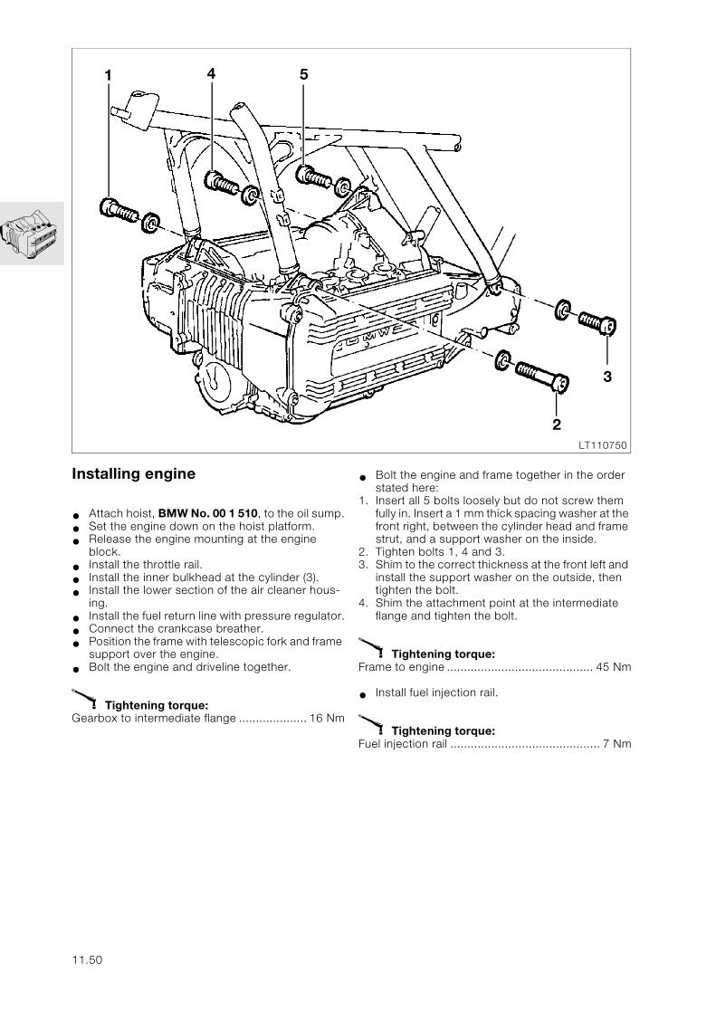
Installing engine
• Attach hoist, BMW No. 00 1 510, to the oil sump.
• Set the engine down on the hoist platform.
• Release the engine mounting at the engine block.
• Install the throttle rail.
• Install the inner bulkhead at the cylinder (3).
• Install the lower section of the air cleaner hous-ing.
• Install the fuel return line with pressure regulator.
• Connect the crankcase breather.
• Position the frame with telescopic fork and frame support over the engine.
• Bolt the engine and driveline together.
X Tightening torque:Gearbox to intermediate flange .................... 16 Nm
• Bolt the engine and frame together in the order stated here:
1. Insert all 5 bolts loosely but do not screw them fully in. Insert a 1 mm thick spacing washer at the front right, between the cylinder head and frame strut, and a support washer on the inside.
2. Tighten bolts 1, 4 and 3.3. Shim to the correct thickness at the front left and
install the support washer on the outside, then tighten the bolt.
4. Shim the attachment point at the intermediate flange and tighten the bolt.
X Tightening torque:Frame to engine ........................................... 45 Nm
• Install fuel injection rail.
X Tightening torque:Fuel injection rail ............................................ 7 Nm
1
2
3
4 5
LT110750
11.50
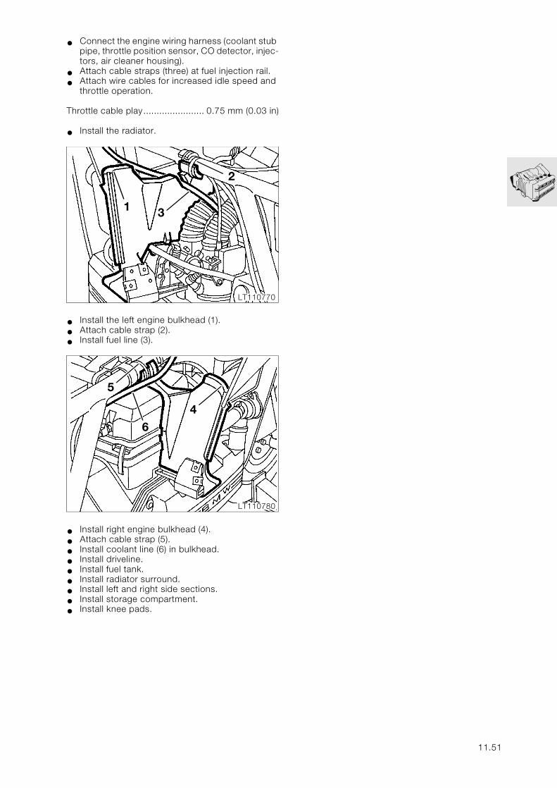
• Connect the engine wiring harness (coolant stub pipe, throttle position sensor, CO detector, injec-tors, air cleaner housing).
• Attach cable straps (three) at fuel injection rail.
• Attach wire cables for increased idle speed and throttle operation.
Throttle cable play....................... 0.75 mm (0.03 in)
• Install the radiator.
• Install the left engine bulkhead (1).
• Attach cable strap (2).
• Install fuel line (3).
• Install right engine bulkhead (4).
• Attach cable strap (5).
• Install coolant line (6) in bulkhead.
• Install driveline.
• Install fuel tank.
• Install radiator surround.
• Install left and right side sections.
• Install storage compartment.
• Install knee pads.
1
2
3
LT110770
4
5
6
LT110780
11.51
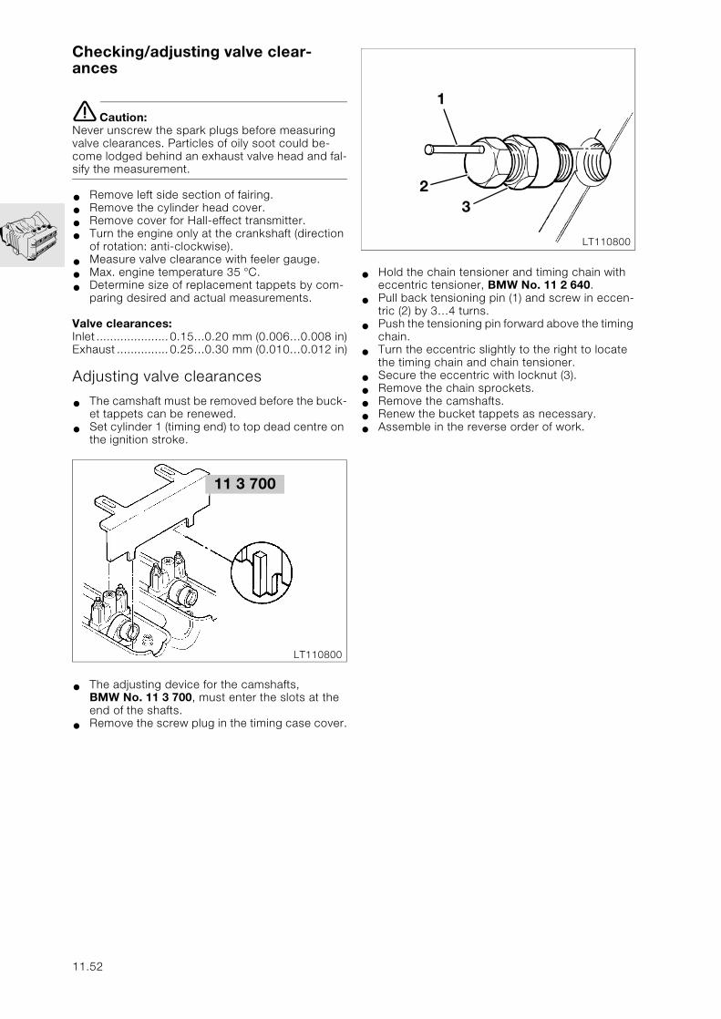
Checking/adjusting valve clear-ances
e Caution:Never unscrew the spark plugs before measuring valve clearances. Particles of oily soot could be-come lodged behind an exhaust valve head and fal-sify the measurement.
• Remove left side section of fairing.
• Remove the cylinder head cover.
• Remove cover for Hall-effect transmitter.
• Turn the engine only at the crankshaft (direction of rotation: anti-clockwise).
• Measure valve clearance with feeler gauge.
• Max. engine temperature 35 °C.
• Determine size of replacement tappets by com-paring desired and actual measurements.
Valve clearances:Inlet .....................0.15…0.20 mm (0.006…0.008 in)Exhaust ...............0.25…0.30 mm (0.010…0.012 in)
Adjusting valve clearances
• The camshaft must be removed before the buck-et tappets can be renewed.
• Set cylinder 1 (timing end) to top dead centre on the ignition stroke.
• The adjusting device for the camshafts,BMW No. 11 3 700, must enter the slots at the end of the shafts.
• Remove the screw plug in the timing case cover.
• Hold the chain tensioner and timing chain with eccentric tensioner, BMW No. 11 2 640.
• Pull back tensioning pin (1) and screw in eccen-tric (2) by 3…4 turns.
• Push the tensioning pin forward above the timing chain.
• Turn the eccentric slightly to the right to locate the timing chain and chain tensioner.
• Secure the eccentric with locknut (3).
• Remove the chain sprockets.
• Remove the camshafts.
• Renew the bucket tappets as necessary.
• Assemble in the reverse order of work.
11 3 700
LT110800
1
23
LT110800
11.52
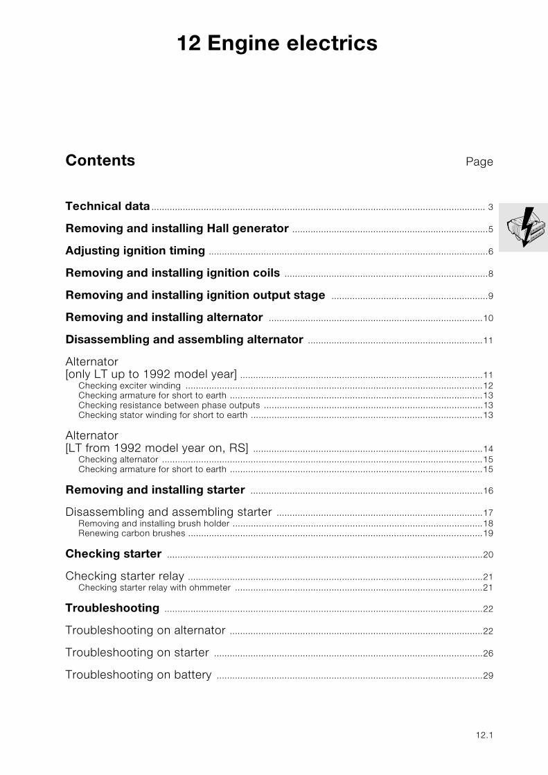
12
Contents Page
12 Engine electrics
Technical data ................................................................................................................................ 3
Removing and installing Hall generator ...........................................................................5
Adjusting ignition timing ...........................................................................................................6
Removing and installing ignition coils ..............................................................................8
Removing and installing ignition output stage ............................................................9
Removing and installing alternator ..................................................................................10
Disassembling and assembling alternator ...................................................................11
Alternator [only LT up to 1992 model year] .............................................................................................11
Checking exciter winding ..................................................................................................................12Checking armature for short to earth .................................................................................................13Checking resistance between phase outputs ....................................................................................13Checking stator winding for short to earth .........................................................................................13
Alternator [LT from 1992 model year on, RS] ........................................................................................14
Checking alternator ...........................................................................................................................15Checking armature for short to earth .................................................................................................15
Removing and installing starter .........................................................................................16
Disassembling and assembling starter ...............................................................................17Removing and installing brush holder ................................................................................................18Renewing carbon brushes .................................................................................................................19
Checking starter .........................................................................................................................20
Checking starter relay .................................................................................................................21Checking starter relay with ohmmeter ...............................................................................................21
Troubleshooting ..........................................................................................................................22
Troubleshooting on alternator .................................................................................................22
Troubleshooting on starter .......................................................................................................26
Troubleshooting on battery ......................................................................................................29
12.1

12.2
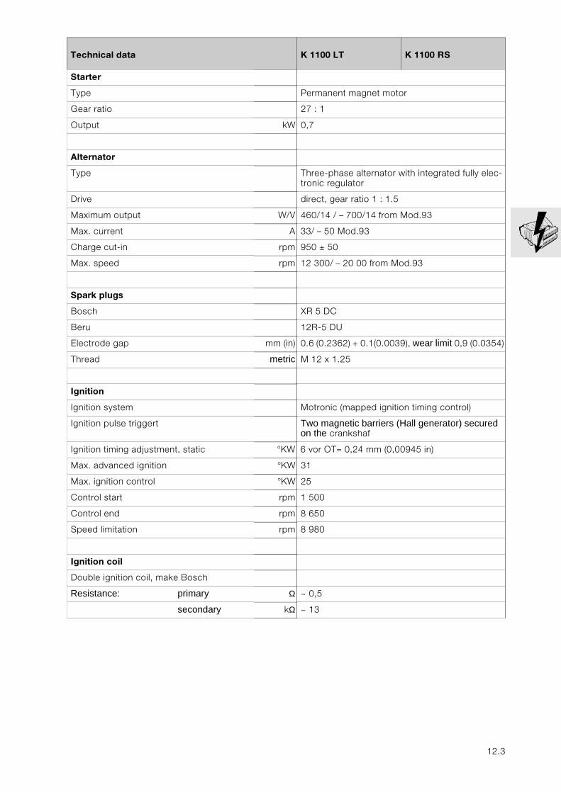
12
Technical data K 1100 LT K 1100 RS
Starter
Type Permanent magnet motor
Gear ratio 27 : 1
Output kW 0,7
Alternator
Type Three-phase alternator with integrated fully elec-tronic regulator
Drive direct, gear ratio 1 : 1.5
Maximum output W/V 460/14 / – 700/14 from Mod.93
Max. current A 33/ – 50 Mod.93
Charge cut-in rpm 950 ± 50
Max. speed rpm 12 300/ – 20 00 from Mod.93
Spark plugs
Bosch XR 5 DC
Beru 12R-5 DU
Electrode gap mm (in) 0.6 (0.2362) + 0.1(0.0039), wear limit 0,9 (0.0354)
Thread metric M 12 x 1.25
Ignition
Ignition system Motronic (mapped ignition timing control)
Ignition pulse triggert Two magnetic barriers (Hall generator) secured on the crankshaf
Ignition timing adjustment, static °KW 6 vor OT= 0,24 mm (0,00945 in)
Max. advanced ignition °KW 31
Max. ignition control °KW 25
Control start rpm 1 500
Control end rpm 8 650
Speed limitation rpm 8 980
Ignition coil
Double ignition coil, make Bosch
Resistance: primary Ω ~ 0,5
secondary kΩ ~ 13
12.3

12.4
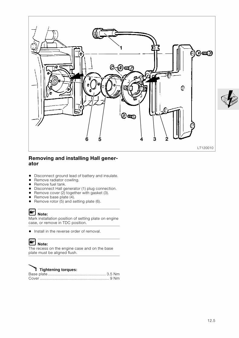
Removing and installing Hall gener-ator
• Disconnect ground lead of battery and insulate.• Remove radiator cowling.• Remove fuel tank.• Disconnect Hall generator (1) plug connection.• Remove cover (2) together with gasket (3).• Remove base plate (4).• Remove rotor (5) and setting plate (6).
L Note:Mark installation position of setting plate on engine case, or remove in TDC position.
• Install in the reverse order of removal.
L Note:The recess on the engine case and on the base plate must be aligned flush.
X Tightening torques:Base plate................................................... 3.5 NmCover ............................................................. 9 Nm
LT120010
6
1
5 4 3 2
12.5
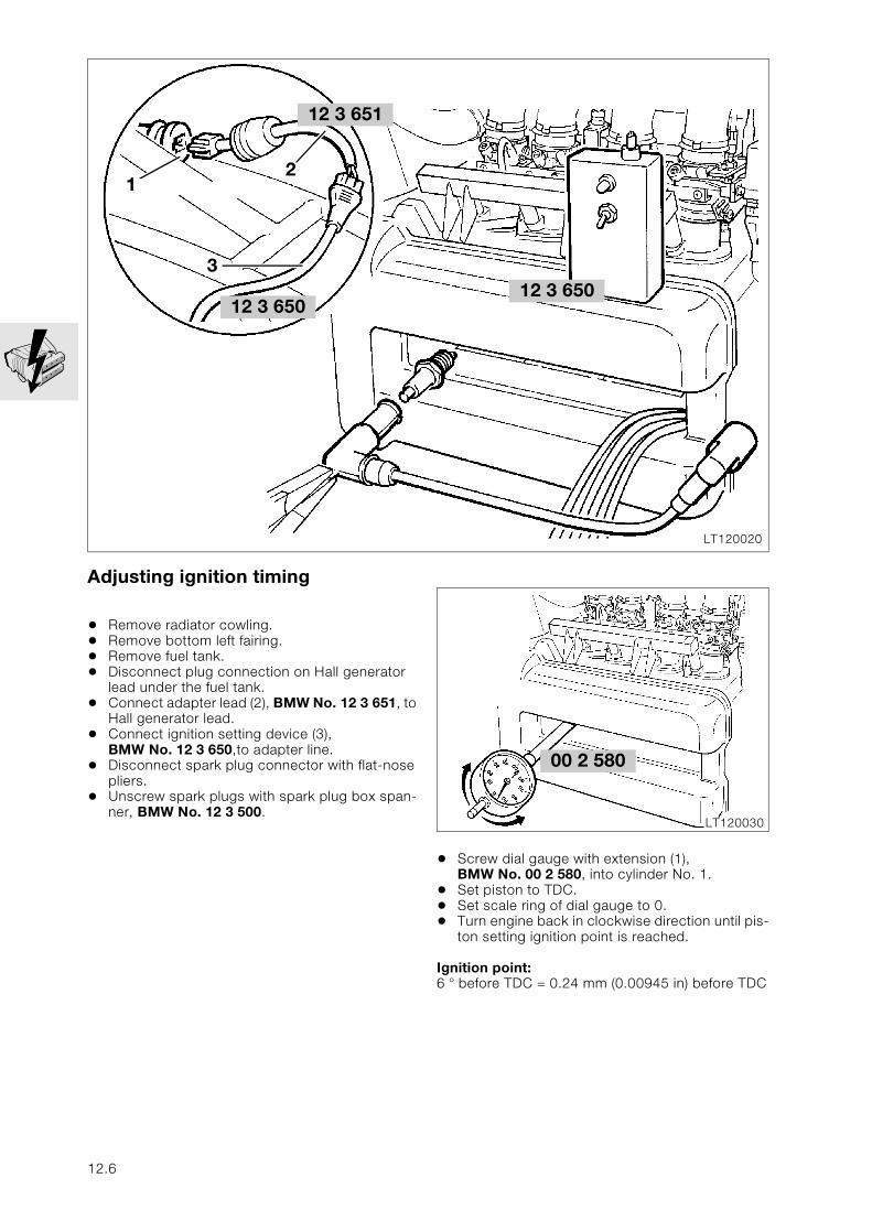
Adjusting ignition timing
• Remove radiator cowling.• Remove bottom left fairing.• Remove fuel tank.• Disconnect plug connection on Hall generator
lead under the fuel tank.• Connect adapter lead (2), BMW No. 12 3 651, to
Hall generator lead.• Connect ignition setting device (3),
BMW No. 12 3 650,to adapter line.• Disconnect spark plug connector with flat-nose
pliers.• Unscrew spark plugs with spark plug box span-
ner, BMW No. 12 3 500.
• Screw dial gauge with extension (1), BMW No. 00 2 580, into cylinder No. 1.
• Set piston to TDC.• Set scale ring of dial gauge to 0.• Turn engine back in clockwise direction until pis-
ton setting ignition point is reached.
Ignition point:6 ° before TDC = 0.24 mm (0.00945 in) before TDC
LT120020
21
3
12 3 650
12 3 651
12 3 650
00 2 580
LT120030
12.6
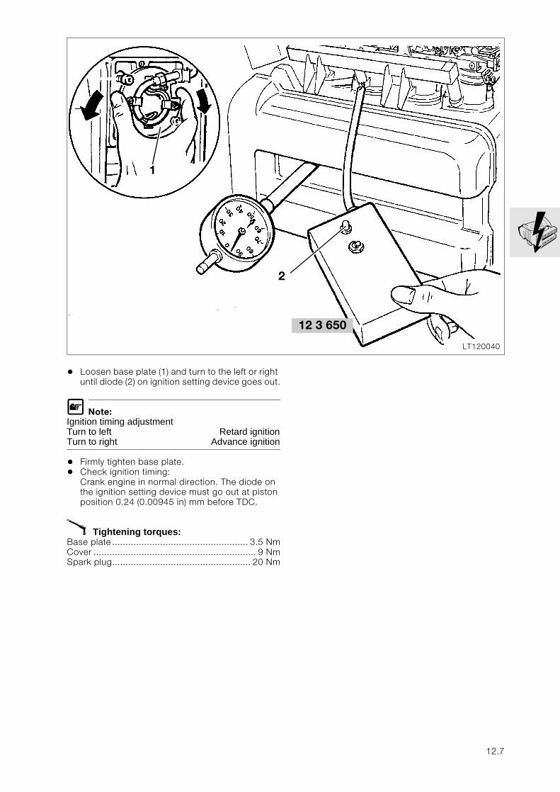
• Loosen base plate (1) and turn to the left or right until diode (2) on ignition setting device goes out.
L Note:Ignition timing adjustmentTurn to left Retard ignitionTurn to right Advance ignition
• Firmly tighten base plate.• Check ignition timing:
Crank engine in normal direction. The diode on the ignition setting device must go out at piston position 0.24 (0.00945 in) mm before TDC.
X Tightening torques:Base plate................................................... 3.5 NmCover ............................................................. 9 NmSpark plug.................................................... 20 Nm
12 3 650
LT120040
1
2
12.7
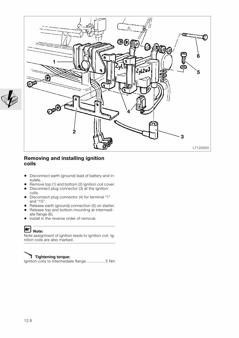
Removing and installing ignition coils
• Disconnect earth (ground) lead of battery and in-sulate.
• Remove top (1) and bottom (2) ignition coil cover.• Disconnect plug connector (3) at the ignition
coils.• Disconnect plug connector (4) for terminal “1”
and “15”.• Release earth (ground) connection (5) on starter.• Release top and bottom mounting at intermedi-
ate flange (6).• Install in the reverse order of removal.
L Note:Note assignment of ignition leads to ignition coil. Ig-nition coils are also marked.
X Tightening torque:Ignition coils to intermediate flange ................ 5 Nm
LT120050
1
4
6
23
5
12.8
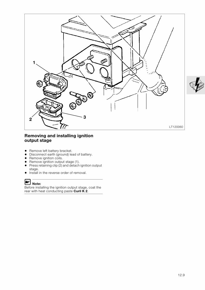
Removing and installing ignition output stage
• Remove left battery bracket.• Disconnect earth (ground) lead of battery.• Remove ignition coils.• Remove ignition output stage (1).• Press retaining clip (2) and detach ignition output
stage.• Install in the reverse order of removal.
L Note:Before installing the ignition output stage, coat the rear with heat conducting paste Curil K 2.
LT120060
32
1
12.9
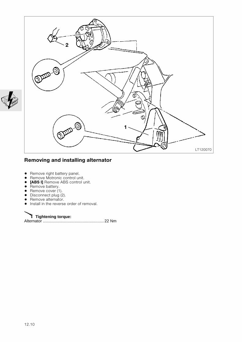
Removing and installing alternator
• Remove right battery panel.• Remove Motronic control unit.• [ABS I] Remove ABS control unit.• Remove battery.• Remove cover (1).• Disconnect plug (2).• Remove alternator.• Install in the reverse order of removal.
X Tightening torque:Alternator ...................................................... 22 Nm
LT120070
1
2
12.10
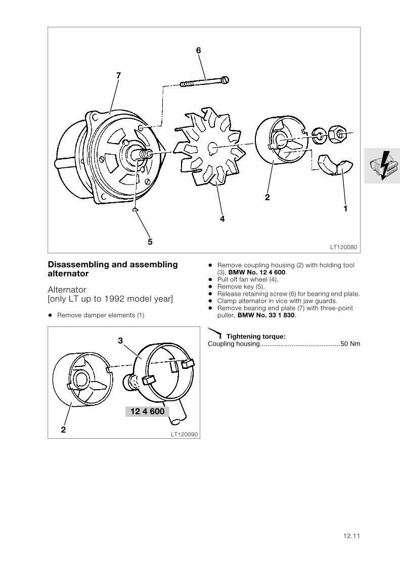
Disassembling and assembling alternator
Alternator [only LT up to 1992 model year]
• Remove damper elements (1)
• Remove coupling housing (2) with holding tool (3), BMW No. 12 4 600.
• Pull off fan wheel (4).• Remove key (5).• Release retaining screw (6) for bearing end plate.• Clamp alternator in vice with jaw guards.• Remove bearing end plate (7) with three-point
puller, BMW No. 33 1 830.
X Tightening torque:Coupling housing...........................................50 Nm
LT1200805
7
6
4
21
12 4 600
LT1200902
3
12.11
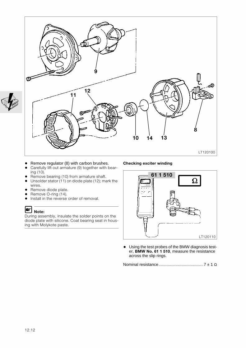
• Remove regulator (8) with carbon brushes.• Carefully lift out armature (9) together with bear-
ing (10).• Remove bearing (10) from armature shaft.• Unsolder stator (11) on diode plate (12); mark the
wires.• Remove diode plate.• Remove O-ring (14).• Install in the reverse order of removal.
L Note:During assembly, insulate the solder points on the diode plate with silicone. Coat bearing seat in hous-ing with Molykote paste.
Checking exciter winding
• Using the test probes of the BMW diagnosis test-er, BMW No. 61 1 510, measure the resistance across the slip rings.
Nominal resistance.......................................7 ± 1 Ω
LT120100
9
11
10 14 13
8
12
61 1 510
LT120110
12.12
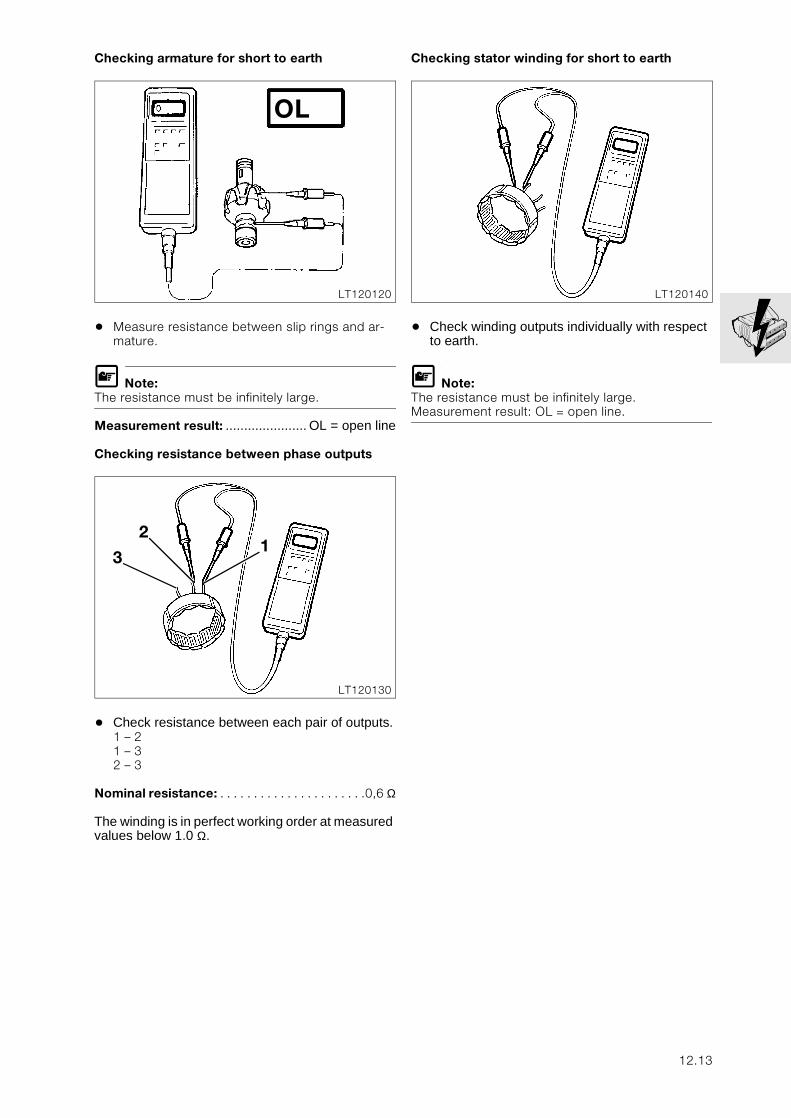
Checking armature for short to earth
• Measure resistance between slip rings and ar-mature.
L Note:The resistance must be infinitely large.
Measurement result: ...................... OL = open line
Checking resistance between phase outputs
• Check resistance between each pair of outputs.1 – 21 – 32 – 3
Nominal resistance: . . . . . . . . . . . . . . . . . . . . . .0,6 Ω
The winding is in perfect working order at measured values below 1.0 Ω.
Checking stator winding for short to earth
• Check winding outputs individually with respect to earth.
L Note:The resistance must be infinitely large.Measurement result: OL = open line.
LT120120
OL
LT120130
12
3
LT120140
12.13
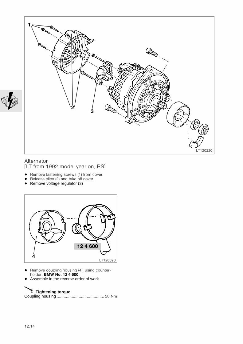
Alternator [LT from 1992 model year on, RS]
• Remove fastening screws (1) from cover.• Release clips (2) and take off cover.• Remove voltage regulator (3)
.
• Remove coupling housing (4), using counter-holder, BMW No. 12 4 600.
• Assemble in the reverse order of work.
X Tightening torque:Coupling housing ......................................... 50 Nm
LT120220
23
1
LT1200904
12 4 600
12.14
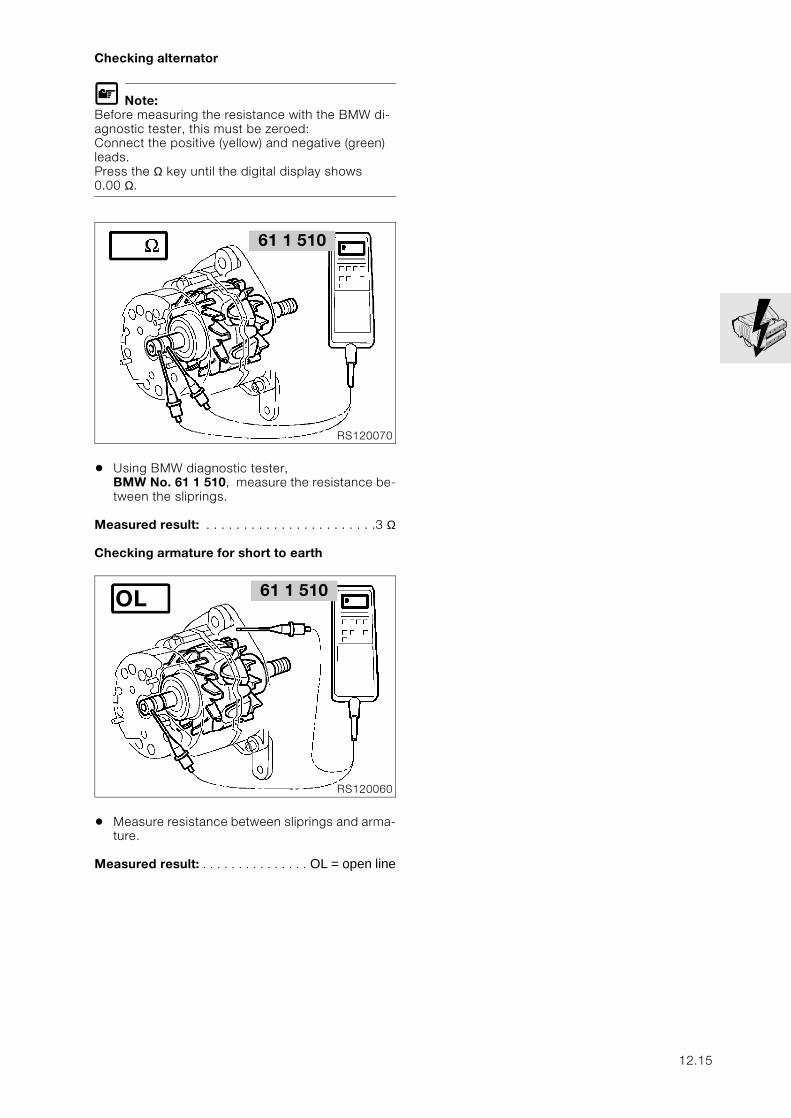
Checking alternator
L Note:Before measuring the resistance with the BMW di-agnostic tester, this must be zeroed:Connect the positive (yellow) and negative (green) leads. Press the Ω key until the digital display shows 0.00 Ω.
• Using BMW diagnostic tester, BMW No. 61 1 510, measure the resistance be-tween the sliprings.
Measured result: . . . . . . . . . . . . . . . . . . . . . . .3 Ω
Checking armature for short to earth
• Measure resistance between sliprings and arma-ture.
Measured result: . . . . . . . . . . . . . . . OL = open line
61 1 510
RS120070
61 1 510
RS120060
OL
12.15
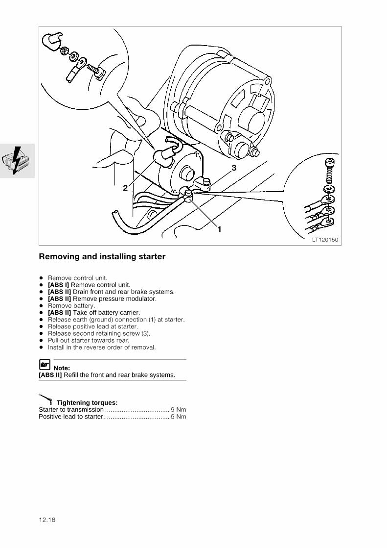
Removing and installing starter
• Remove control unit.• [ABS I] Remove control unit.• [ABS II] Drain front and rear brake systems.• [ABS II] Remove pressure modulator.• Remove battery.• [ABS II] Take off battery carrier.• Release earth (ground) connection (1) at starter.• Release positive lead at starter.• Release second retaining screw (3).• Pull out starter towards rear.• Install in the reverse order of removal.
L Note:[ABS II] Refill the front and rear brake systems.
X Tightening torques:Starter to transmission ................................... 9 NmPositive lead to starter.................................... 5 Nm
LT120150
2
3
1
12.16
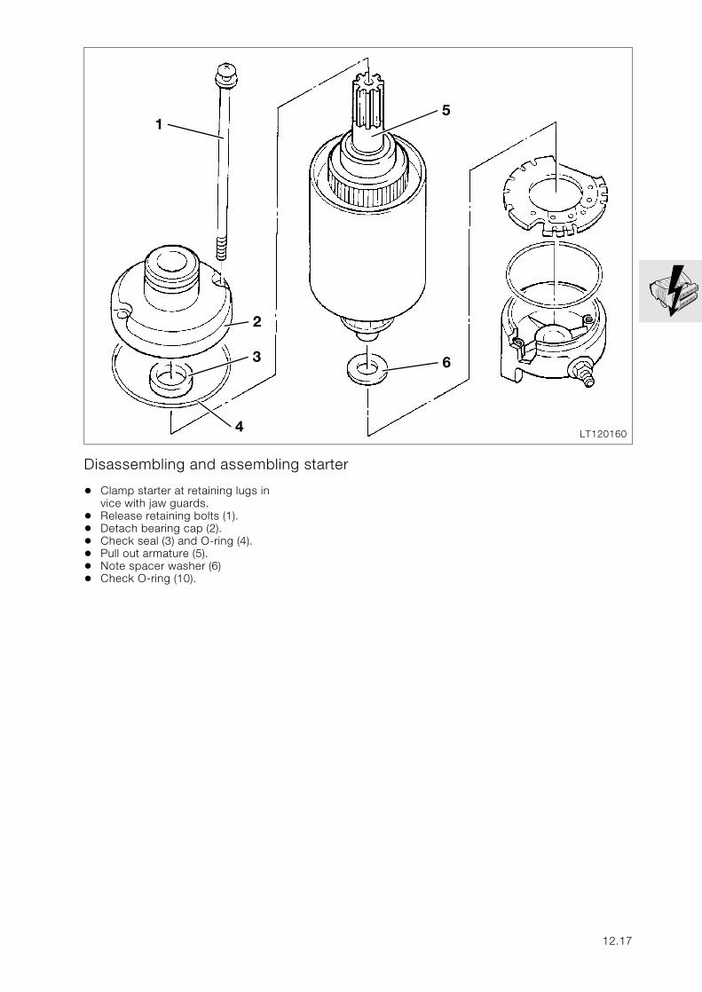
Disassembling and assembling starter
• Clamp starter at retaining lugs in vice with jaw guards.
• Release retaining bolts (1).• Detach bearing cap (2).• Check seal (3) and O-ring (4).• Pull out armature (5).• Note spacer washer (6)• Check O-ring (10).
LT120160
2
3
4
5
6
1
12.17
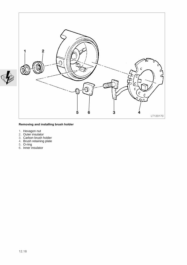
Removing and installing brush holder
1. Hexagon nut2. Outer insulator3. Carbon brush holder4. Brush retaining plate5. O-ring6. Inner insulator
LT1201705
1
436
2
12.18
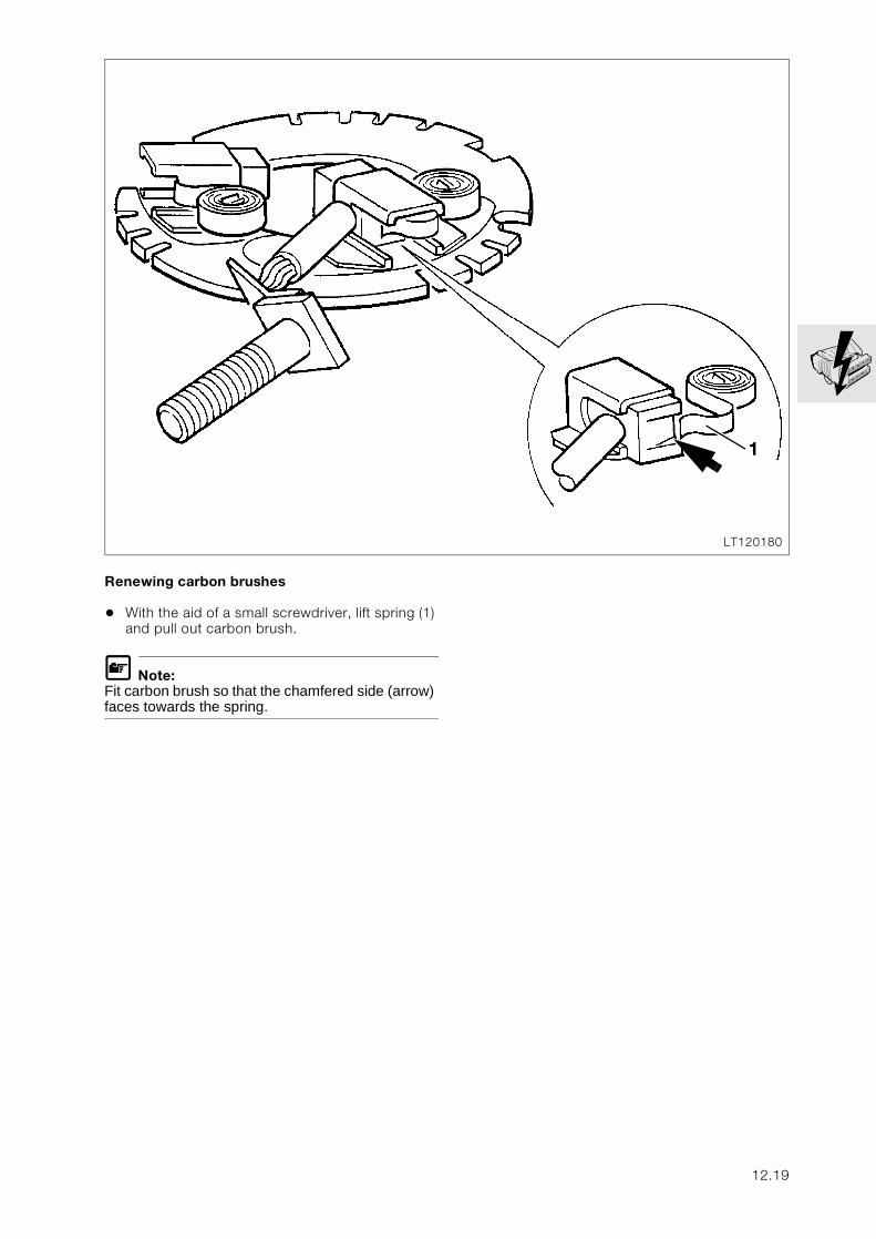
Renewing carbon brushes
• With the aid of a small screwdriver, lift spring (1) and pull out carbon brush.
L Note:Fit carbon brush so that the chamfered side (arrow) faces towards the spring.
LT120180
1
12.19
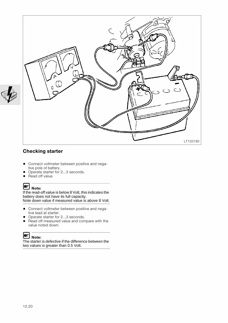
Checking starter
• Connect voltmeter between positive and nega-tive pole of battery.
• Operate starter for 2...3 seconds.• Read off value.
L Note:If the read-off value is below 8 Volt, this indicates the battery does not have its full capacity.Note down value if measured value is above 8 Volt.
• Connect voltmeter between positive and nega-tive lead at starter.
• Operate starter for 2...3 seconds.• Read off measured value and compare with the
value noted down.
L Note:The starter is defective if the difference between the two values is greater than 0.5 Volt.
LT120190
12.20
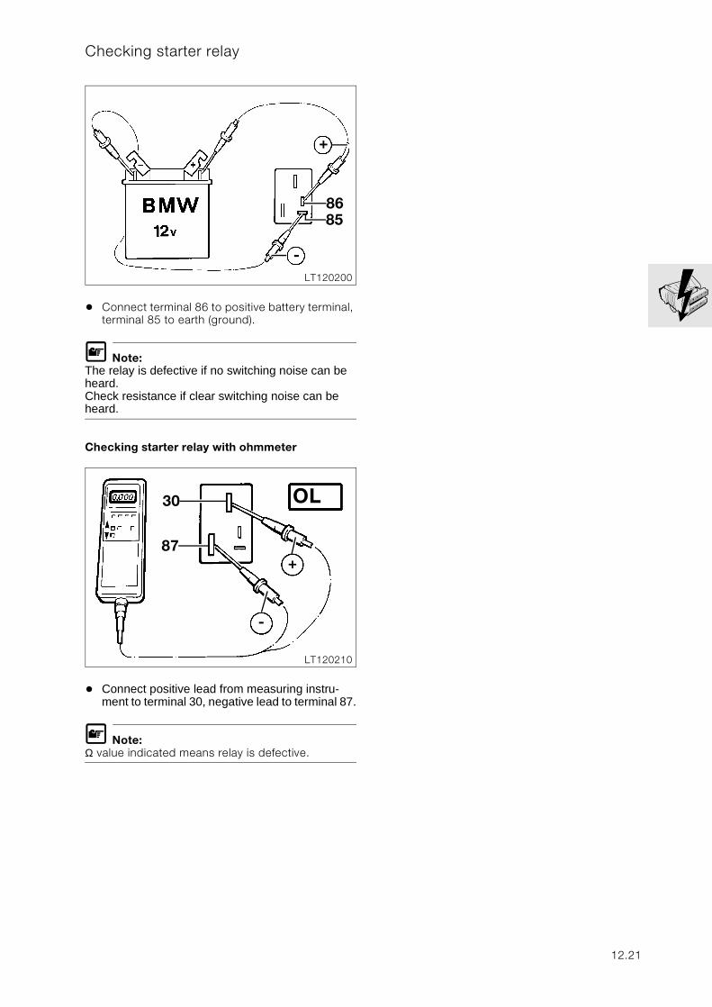
Checking starter relay
• Connect terminal 86 to positive battery terminal, terminal 85 to earth (ground).
L Note:The relay is defective if no switching noise can be heard.Check resistance if clear switching noise can be heard.
Checking starter relay with ohmmeter
• Connect positive lead from measuring instru-ment to terminal 30, negative lead to terminal 87.
L Note:Ω value indicated means relay is defective.
LT120200
+
8685
-
LT120210
30 OL
87
-
+
12.21
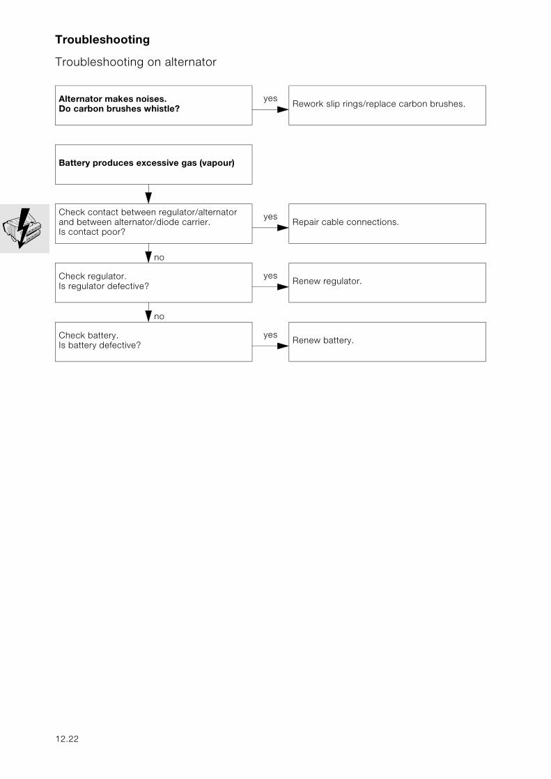
Troubleshooting
Troubleshooting on alternator
Alternator makes noises.Do carbon brushes whistle?
yesRework slip rings/replace carbon brushes.
Battery produces excessive gas (vapour)
no
Check contact between regulator/alternator and between alternator/diode carrier.Is contact poor?
yesRepair cable connections.
no
Check regulator.Is regulator defective?
yesRenew regulator.
no
Check battery.Is battery defective?
yesRenew battery.
12.22
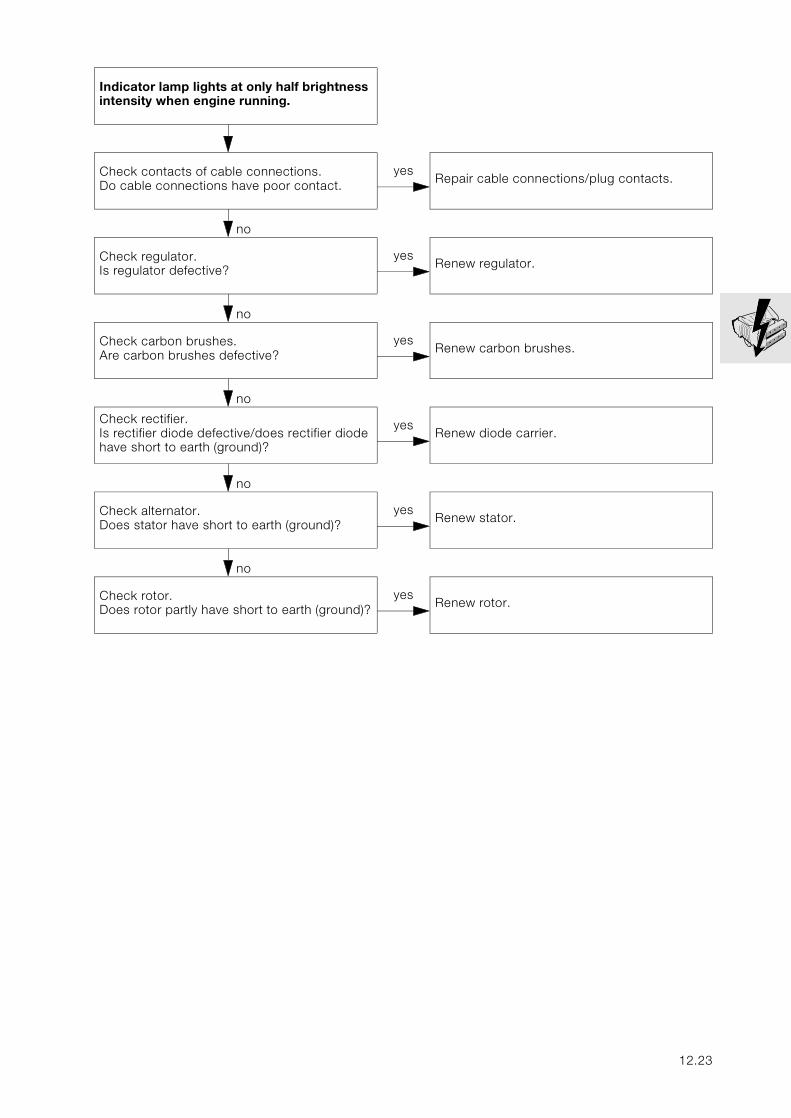
Indicator lamp lights at only half brightness intensity when engine running.
no
Check contacts of cable connections. Do cable connections have poor contact.
yesRepair cable connections/plug contacts.
no
Check regulator.Is regulator defective?
yesRenew regulator.
no
Check carbon brushes.Are carbon brushes defective?
yesRenew carbon brushes.
no
Check rectifier.Is rectifier diode defective/does rectifier diode have short to earth (ground)?
yesRenew diode carrier.
no
Check alternator.Does stator have short to earth (ground)?
yesRenew stator.
no
Check rotor.Does rotor partly have short to earth (ground)?
yesRenew rotor.
12.23
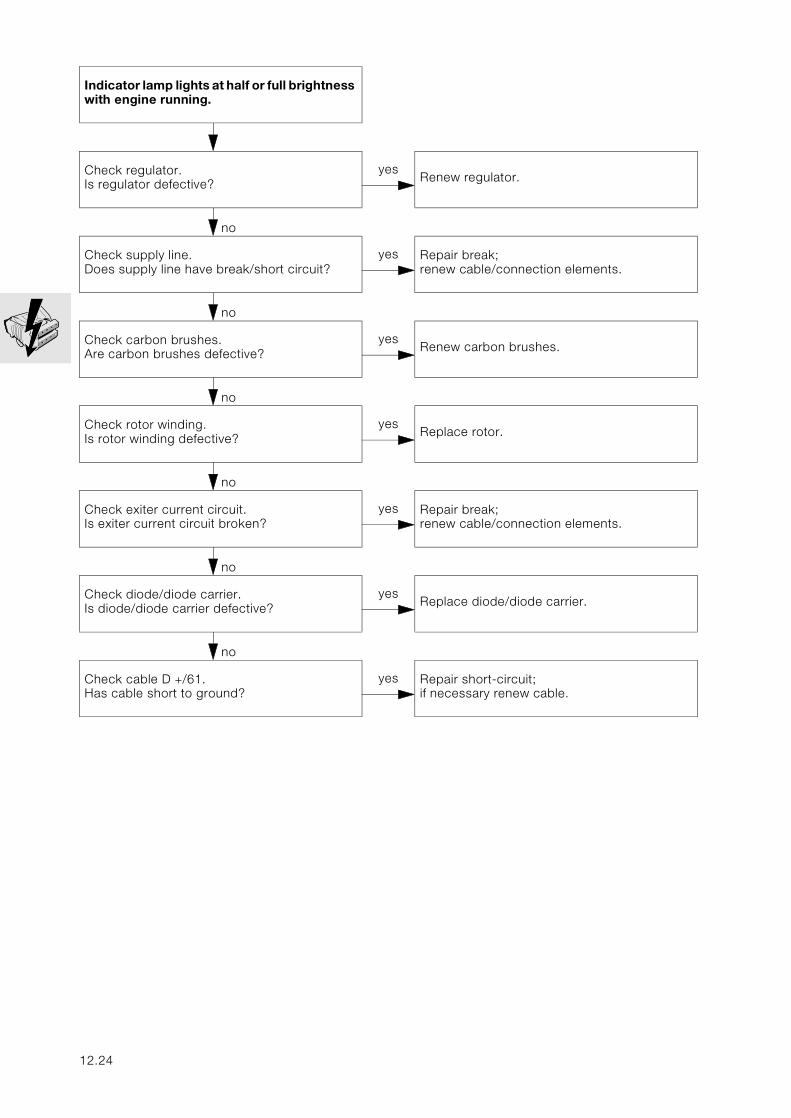
Indicator lamp lights at half or full brightness with engine running.
no
Check regulator.Is regulator defective?
yesRenew regulator.
no
Check supply line. Does supply line have break/short circuit?
yes Repair break; renew cable/connection elements.
no
Check carbon brushes.Are carbon brushes defective?
yesRenew carbon brushes.
no
Check rotor winding.Is rotor winding defective?
yesReplace rotor.
no
Check exiter current circuit.Is exiter current circuit broken?
yes Repair break;renew cable/connection elements.
no
Check diode/diode carrier.Is diode/diode carrier defective?
yesReplace diode/diode carrier.
no
Check cable D +/61.Has cable short to ground?
yes Repair short-circuit; if necessary renew cable.
12.24
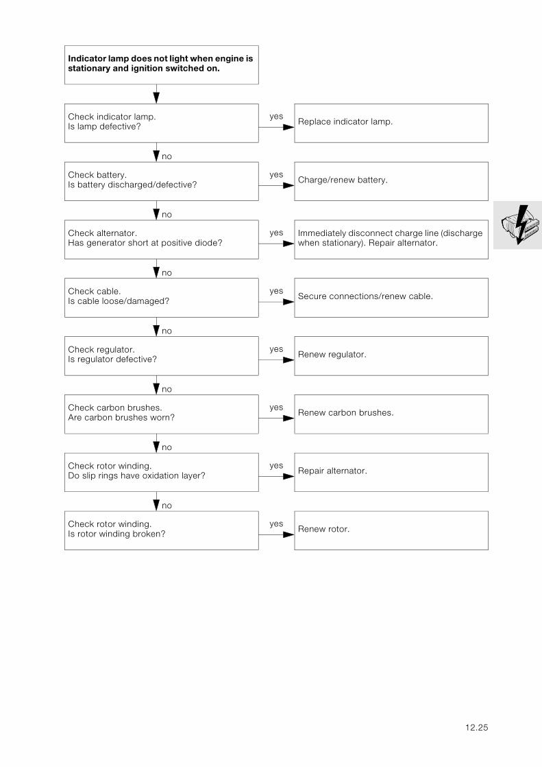
Indicator lamp does not light when engine is stationary and ignition switched on.
no
Check indicator lamp.Is lamp defective?
yesReplace indicator lamp.
no
Check battery.Is battery discharged/defective?
yesCharge/renew battery.
no
Check alternator.Has generator short at positive diode?
yes Immediately disconnect charge line (discharge when stationary). Repair alternator.
no
Check cable.Is cable loose/damaged?
yesSecure connections/renew cable.
no
Check regulator.Is regulator defective?
yesRenew regulator.
no
Check carbon brushes.Are carbon brushes worn?
yesRenew carbon brushes.
no
Check rotor winding.Do slip rings have oxidation layer?
yesRepair alternator.
no
Check rotor winding.Is rotor winding broken?
yesRenew rotor.
12.25
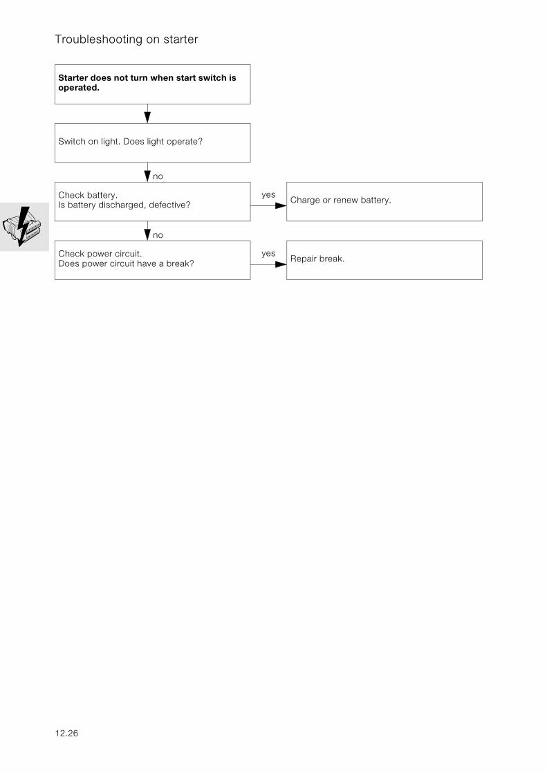
Troubleshooting on starter
Starter does not turn when start switch is operated.
no
Switch on light. Does light operate?
no
Check battery.Is battery discharged, defective?
yesCharge or renew battery.
no
Check power circuit.Does power circuit have a break?
yesRepair break.
12.26
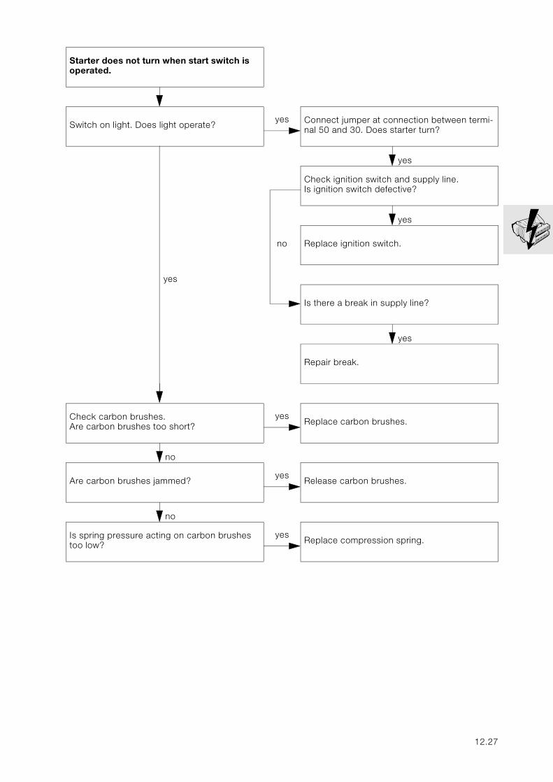
Starter does not turn when start switch is operated.
no
Switch on light. Does light operate?yes Connect jumper at connection between termi-
nal 50 and 30. Does starter turn?
yes
Check ignition switch and supply line.Is ignition switch defective?
yes
no Replace ignition switch.
yes
Is there a break in supply line?
yes
Repair break.
no
Check carbon brushes.Are carbon brushes too short?
yesReplace carbon brushes.
no
Are carbon brushes jammed?yes
Release carbon brushes.
no
Is spring pressure acting on carbon brushes too low?
yesReplace compression spring.
12.27
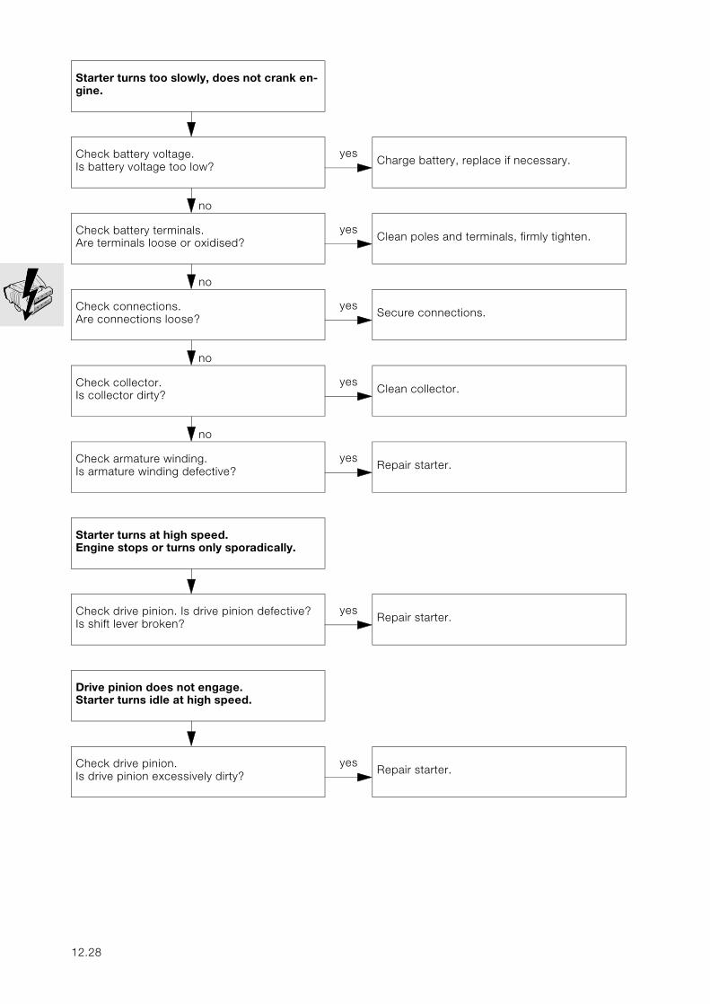
Starter turns too slowly, does not crank en-gine.
no
Check battery voltage.Is battery voltage too low?
yesCharge battery, replace if necessary.
no
Check battery terminals.Are terminals loose or oxidised?
yesClean poles and terminals, firmly tighten.
no
Check connections.Are connections loose?
yesSecure connections.
no
Check collector.Is collector dirty?
yesClean collector.
no
Check armature winding. Is armature winding defective?
yesRepair starter.
Starter turns at high speed.Engine stops or turns only sporadically.
no
Check drive pinion. Is drive pinion defective?Is shift lever broken?
yesRepair starter.
Drive pinion does not engage.Starter turns idle at high speed.
no
Check drive pinion.Is drive pinion excessively dirty?
yesRepair starter.
12.28
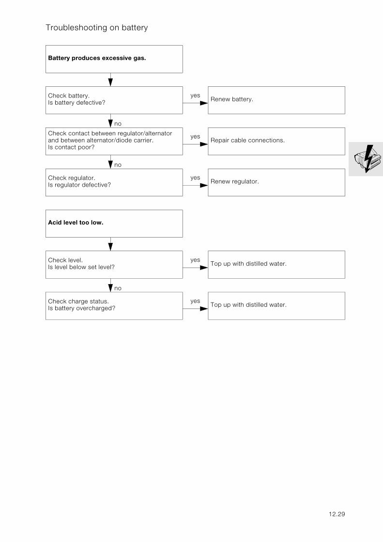
Troubleshooting on battery
Battery produces excessive gas.
no
Check battery.Is battery defective?
yesRenew battery.
no
Check contact between regulator/alternator and between alternator/diode carrier.Is contact poor?
yesRepair cable connections.
no
Check regulator.Is regulator defective?
yesRenew regulator.
Acid level too low.
no
Check level.Is level below set level?
yesTop up with distilled water.
no
Check charge status.Is battery overcharged?
yesTop up with distilled water.
12.29
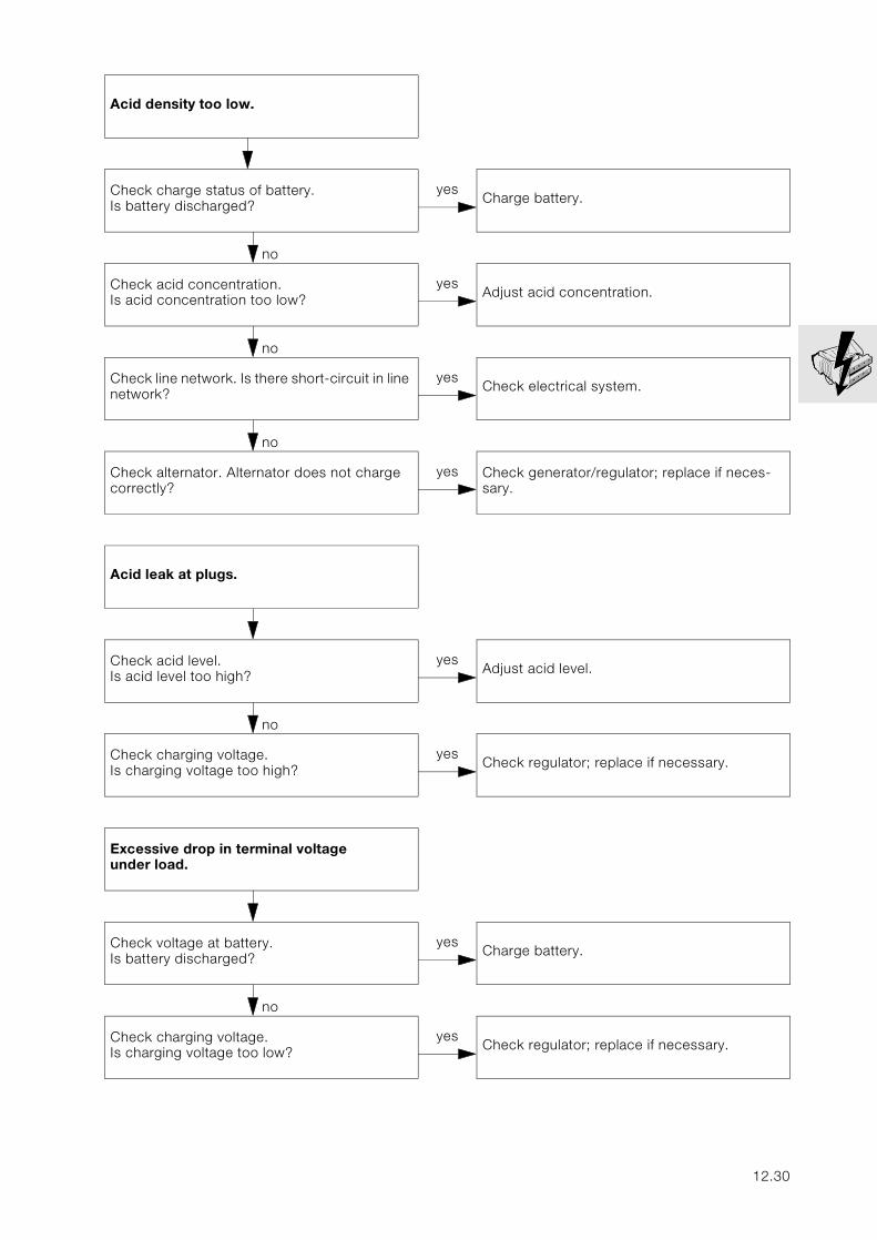
Acid density too low.
nein
Check charge status of battery.Is battery discharged?
yesCharge battery.
no
Check acid concentration.Is acid concentration too low?
yesAdjust acid concentration.
no
Check line network. Is there short-circuit in line network?
yesCheck electrical system.
no
Check alternator. Alternator does not charge correctly?
yes Check generator/regulator; replace if neces-sary.
Acid leak at plugs.
no
Check acid level.Is acid level too high?
yesAdjust acid level.
no
Check charging voltage.Is charging voltage too high?
yesCheck regulator; replace if necessary.
Excessive drop in terminal voltageunder load.
no
Check voltage at battery.Is battery discharged?
yesCharge battery.
no
Check charging voltage.Is charging voltage too low?
yesCheck regulator; replace if necessary.
12.30
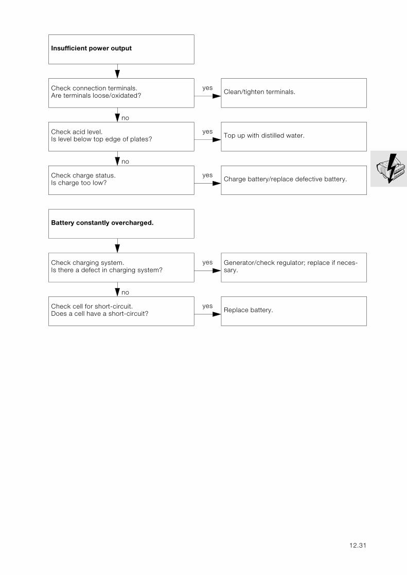
Insufficient power output
no
Check connection terminals.Are terminals loose/oxidated?
yesClean/tighten terminals.
no
Check acid level.Is level below top edge of plates?
yesTop up with distilled water.
no
Check charge status.Is charge too low?
yesCharge battery/replace defective battery.
Battery constantly overcharged.
no
Check charging system. Is there a defect in charging system?
yes Generator/check regulator; replace if neces-sary.
no
Check cell for short-circuit.Does a cell have a short-circuit?
yesReplace battery.
12.31

12.32
13
Contents Page
13 Fuel preparation and control
Technical data ................................................................................................................................ 3
Adjusting idle speed ...................................................................................................................5
Checking start speed increase (choke), adjusting if necessary ........................6
Checking start speed increase .................................................................................................6
Adjusting start speed increase .................................................................................................6
Adjusting CO value ......................................................................................................................7
Removing/installing and checking/adjusting throttle position sensor ...........8
Removing and installing throttle position sensor ..............................................................8
Checking trottle position sensor ..............................................................................................8
Adjusting throttle position sensor ............................................................................................8
Removing and installing air cleaner insert .....................................................................9
Removing and installing air cleaner housing ..............................................................10
Removing and installing throttle rail ................................................................................12
Removing and installing injectors ..........................................................................................13
Removing and installing intake stub pipe ..........................................................................13
Removing and installing Motronic control unit .........................................................14
13.1

13.2
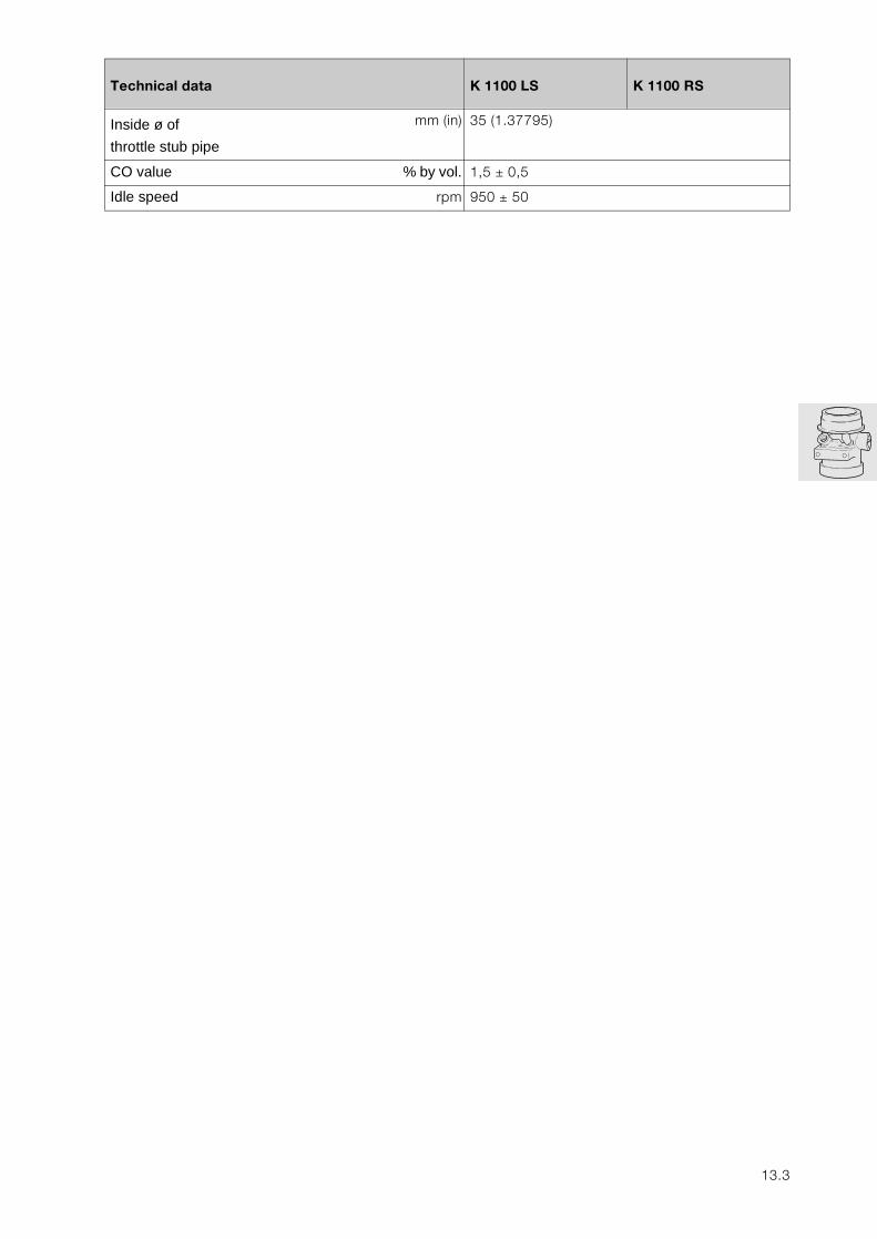
13
Technical data K 1100 LS K 1100 RS
Inside ø of
throttle stub pipe
mm (in) 35 (1.37795)
CO value % by vol. 1,5 ± 0,5
Idle speed rpm 950 ± 50
13.3
13.4
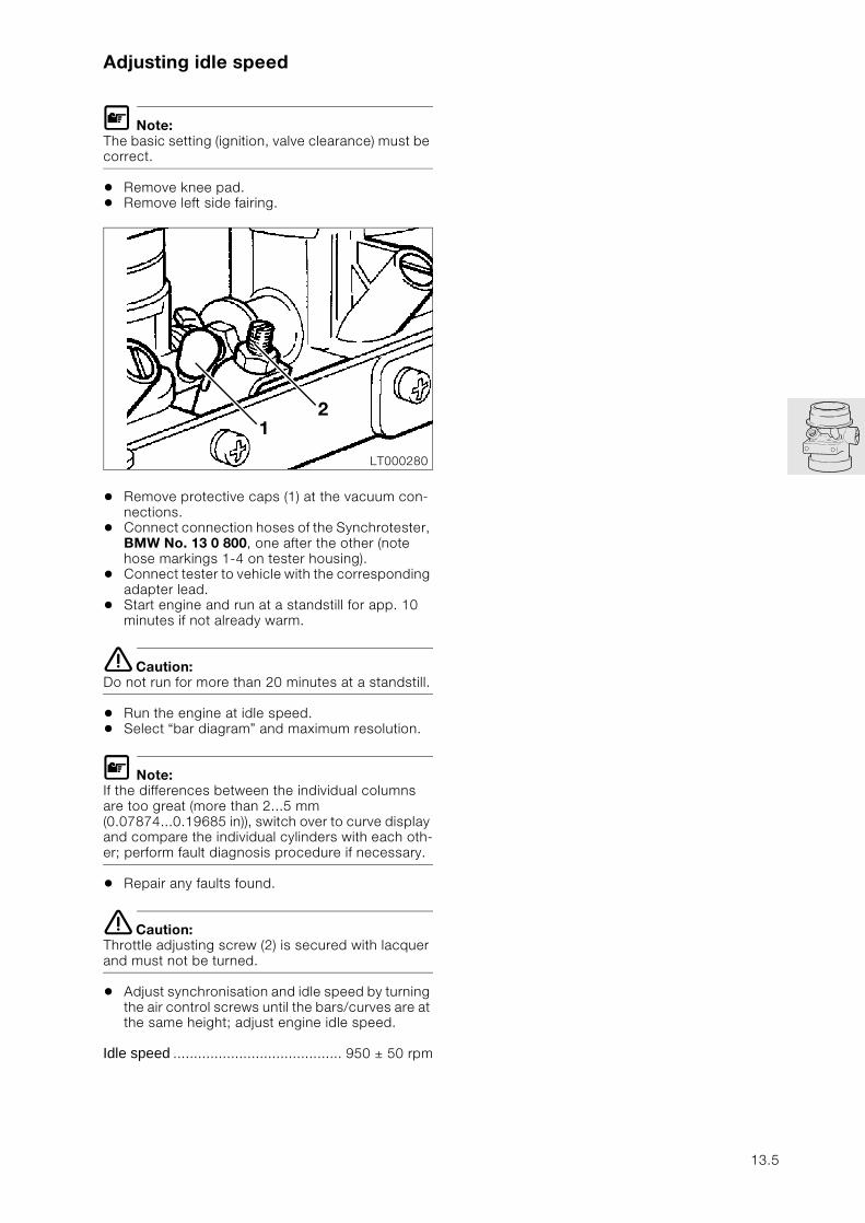
Adjusting idle speed
L Note:The basic setting (ignition, valve clearance) must be correct.
• Remove knee pad.• Remove left side fairing.
• Remove protective caps (1) at the vacuum con-nections.
• Connect connection hoses of the Synchrotester, BMW No. 13 0 800, one after the other (note hose markings 1-4 on tester housing).
• Connect tester to vehicle with the corresponding adapter lead.
• Start engine and run at a standstill for app. 10 minutes if not already warm.
e Caution:Do not run for more than 20 minutes at a standstill.
• Run the engine at idle speed.• Select “bar diagram” and maximum resolution.
L Note:If the differences between the individual columns are too great (more than 2...5 mm (0.07874...0.19685 in)), switch over to curve display and compare the individual cylinders with each oth-er; perform fault diagnosis procedure if necessary.
• Repair any faults found.
e Caution:Throttle adjusting screw (2) is secured with lacquer and must not be turned.
• Adjust synchronisation and idle speed by turning the air control screws until the bars/curves are at the same height; adjust engine idle speed.
Idle speed ......................................... 950 ± 50 rpm
LT000280
21
13.5
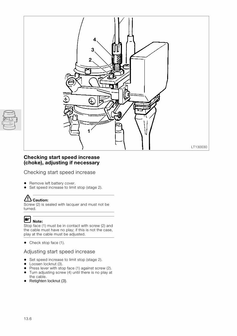
Checking start speed increase (choke), adjusting if necessary
Checking start speed increase
• Remove left battery cover.• Set speed increase to limit stop (stage 2).
e Caution:Screw (2) is sealed with lacquer and must not be turned.
L Note:Stop face (1) must be in contact with screw (2) and the cable must have no play; if this is not the case, play at the cable must be adjusted.
• Check stop face (1).
Adjusting start speed increase
• Set speed increase to limit stop (stage 2).• Loosen locknut (3).• Press lever with stop face (1) against screw (2).• Turn adjusting screw (4) until there is no play at
the cable.• Retighten locknut (3).
LT130030
4
1
3
2
13.6
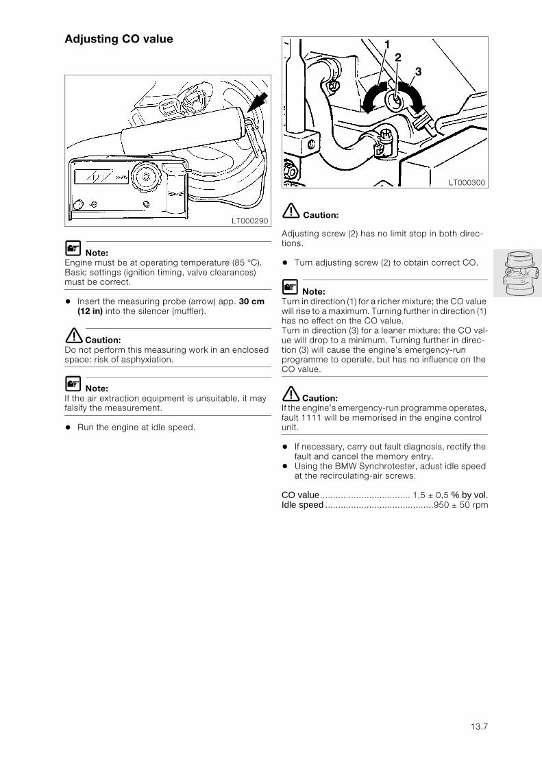
Adjusting CO value
L Note:Engine must be at operating temperature (85 °C).Basic settings (ignition timing, valve clearances) must be correct.
• Insert the measuring probe (arrow) app. 30 cm (12 in) into the silencer (muffler).
e Caution:Do not perform this measuring work in an enclosed space: risk of asphyxiation.
L Note:If the air extraction equipment is unsuitable, it may falsify the measurement.
• Run the engine at idle speed.
e Caution:
Adjusting screw (2) has no limit stop in both direc-tions.
• Turn adjusting screw (2) to obtain correct CO.
L Note:Turn in direction (1) for a richer mixture; the CO value will rise to a maximum. Turning further in direction (1) has no effect on the CO value. Turn in direction (3) for a leaner mixture; the CO val-ue will drop to a minimum. Turning further in direc-tion (3) will cause the engine’s emergency-run programme to operate, but has no influence on the CO value.
e Caution:If the engine’s emergency-run programme operates, fault 1111 will be memorised in the engine control unit.
• If necessary, carry out fault diagnosis, rectify the fault and cancel the memory entry.
• Using the BMW Synchrotester, adust idle speed at the recirculating-air screws.
CO value................................... 1,5 ± 0,5 % by vol.Idle speed ..........................................950 ± 50 rpm
LT000290
LT000300
21
3
13.7
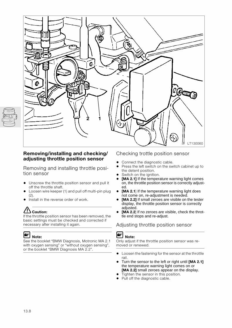
Removing/installing and checking/adjusting throttle position sensor
Removing and installing throttle posi-tion sensor
• Unscrew the throttle position sensor and pull it off the throttle shaft.
• Loosen wire keeper (1) and pull off multi-pin plug (2).
• Install in the reverse order of work.
e Caution:If the throttle position sensor has been removed, the basic settings must be checked and corrected if necessary after installing it again.
L Note:See the booklet “BMW Diagnosis, Motronic MA 2.1 with oxygen sensing” or “without oxygen sensing”, or the booklet “BMW Diagnosis MA 2.2”.
Checking trottle position sensor
• Connect the diagnostic cable.• Press the left switch on the switch cabinet up to
the detent position.• Switch on the ignition.• [MA 2.1] If the temperature warning light comes
on, the throttle position sensor is correctly adjust-ed.
• [MA 2.1] If the temperature warning light does not come on, re-adjustment is needed.
• [MA 2.2] If small zeroes are visible on the tester display, the throttle position sensor is correctly adjusted.
• [MA 2.2] If no zeroes are visible, check the throt-tle end stops and re-adjust.
Adjusting throttle position sensor
L Note:Only adjust if the throttle position sensor was re-moved or renewed.
• Loosen the fastening for the sensor at the throttle rail.
• Turn the sensor to the left or right until [MA 2.1] the temperature warning light comes on or [MA 2.2] small zeroes appear on the display.
• Tighten the sensor in this position.• Pull off the diagnostic cable.
LT130060
2 1
13.8
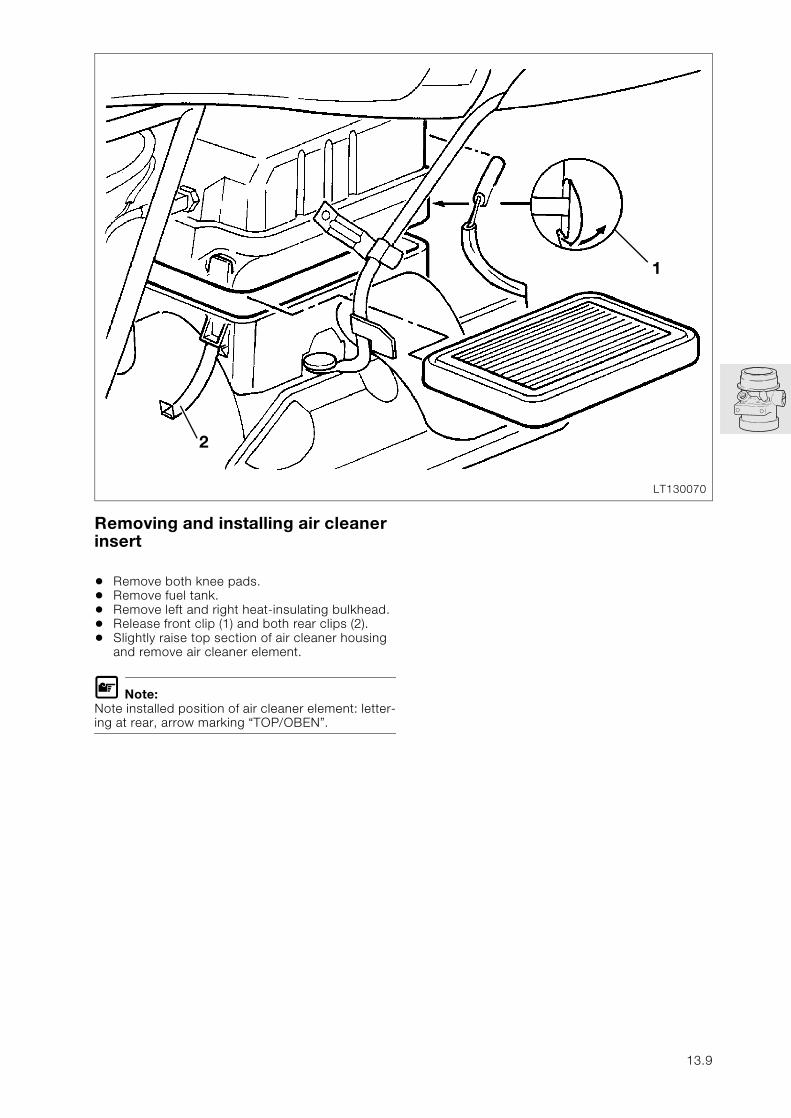
Removing and installing air cleaner insert
• Remove both knee pads.• Remove fuel tank.• Remove left and right heat-insulating bulkhead.• Release front clip (1) and both rear clips (2).• Slightly raise top section of air cleaner housing
and remove air cleaner element.
L Note:Note installed position of air cleaner element: letter-ing at rear, arrow marking “TOP/OBEN”.
LT130070
1
2
13.9
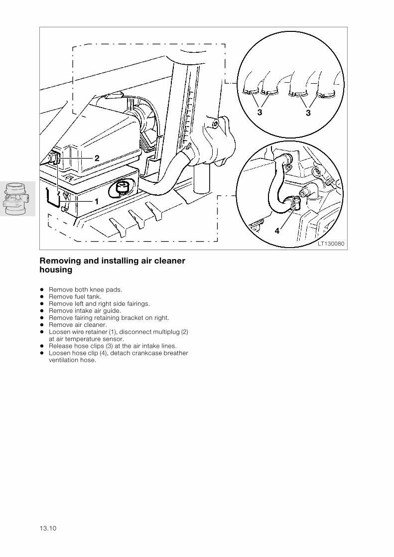
Removing and installing air cleaner housing
• Remove both knee pads.• Remove fuel tank.• Remove left and right side fairings.• Remove intake air guide.• Remove fairing retaining bracket on right.• Remove air cleaner.• Loosen wire retainer (1), disconnect multiplug (2)
at air temperature sensor.• Release hose clips (3) at the air intake lines.• Loosen hose clip (4), detach crankcase breather
ventilation hose.
LT130080
2
1
3
4
3
13.10
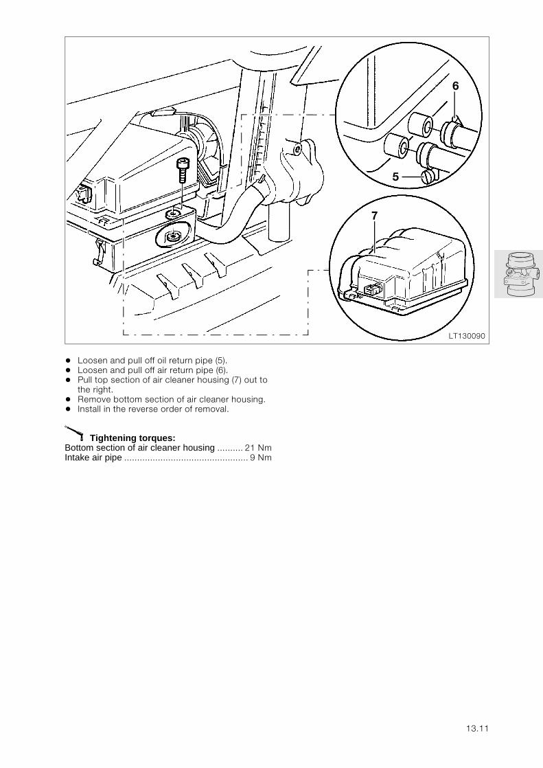
• Loosen and pull off oil return pipe (5).• Loosen and pull off air return pipe (6).• Pull top section of air cleaner housing (7) out to
the right.• Remove bottom section of air cleaner housing.• Install in the reverse order of removal.
X Tightening torques:Bottom section of air cleaner housing .......... 21 NmIntake air pipe ................................................ 9 Nm
LT130090
5
6
7
13.11
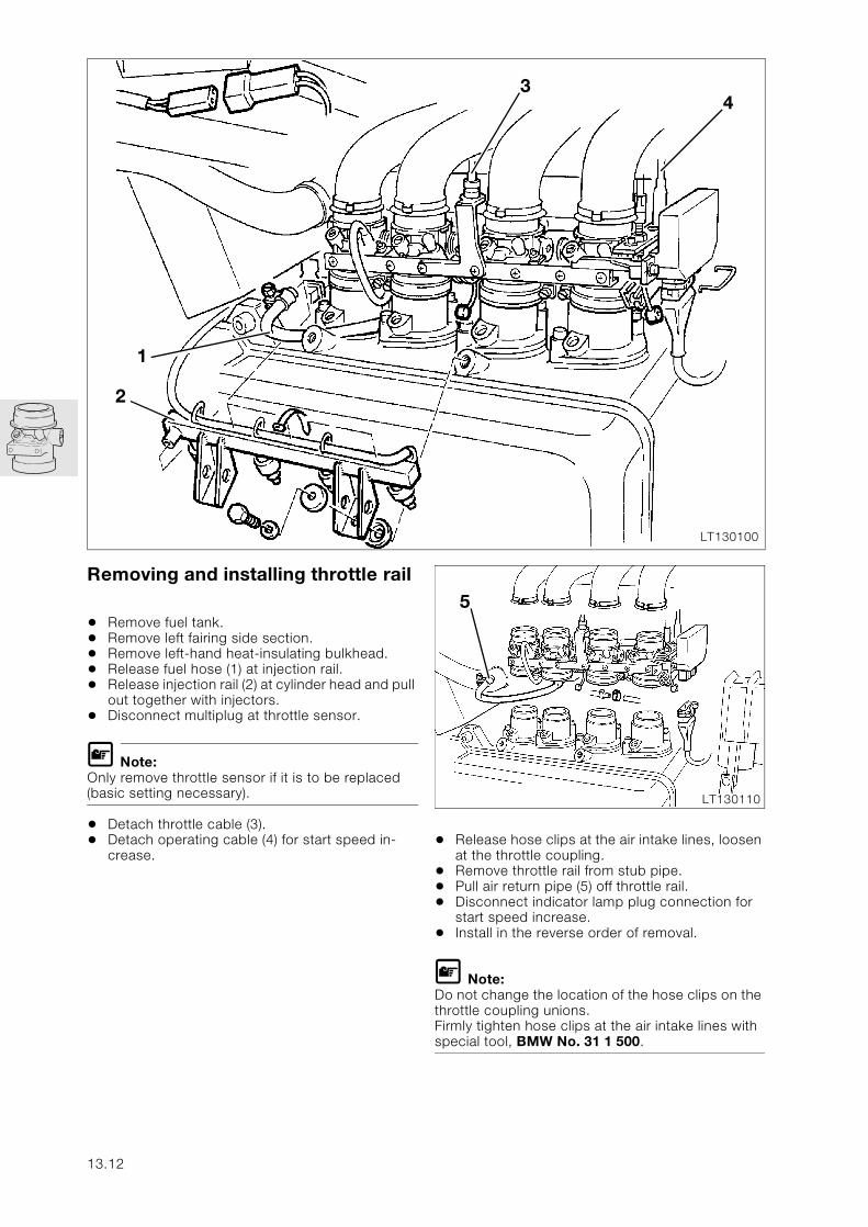
Removing and installing throttle rail
• Remove fuel tank.• Remove left fairing side section.• Remove left-hand heat-insulating bulkhead.• Release fuel hose (1) at injection rail.• Release injection rail (2) at cylinder head and pull
out together with injectors.• Disconnect multiplug at throttle sensor.
L Note:Only remove throttle sensor if it is to be replaced (basic setting necessary).
• Detach throttle cable (3).• Detach operating cable (4) for start speed in-
crease.• Release hose clips at the air intake lines, loosen
at the throttle coupling.• Remove throttle rail from stub pipe.• Pull air return pipe (5) off throttle rail.• Disconnect indicator lamp plug connection for
start speed increase.• Install in the reverse order of removal.
L Note:Do not change the location of the hose clips on the throttle coupling unions.Firmly tighten hose clips at the air intake lines with special tool, BMW No. 31 1 500.
LT130100
1
34
2
LT130110
5
13.12
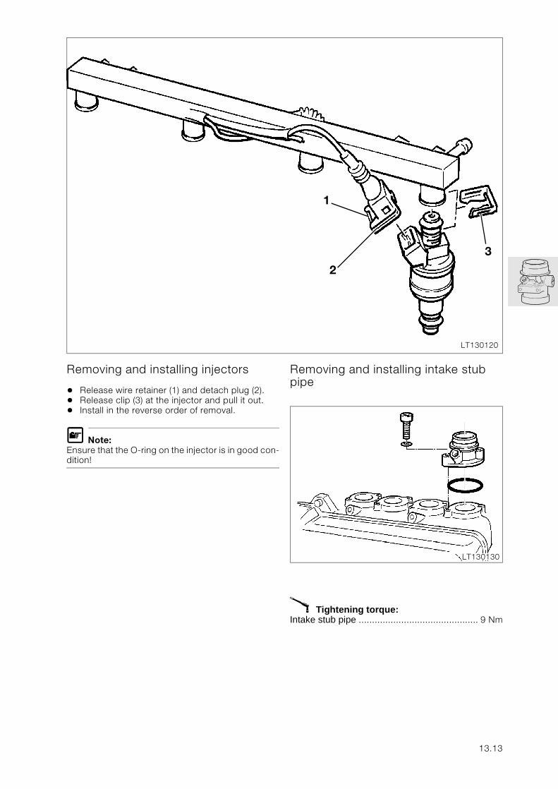
Removing and installing injectors
• Release wire retainer (1) and detach plug (2).• Release clip (3) at the injector and pull it out.• Install in the reverse order of removal.
L Note:Ensure that the O-ring on the injector is in good con-dition!
Removing and installing intake stub pipe
X Tightening torque:Intake stub pipe ............................................. 9 Nm
LT130120
3
2
1
LT130130
13.13
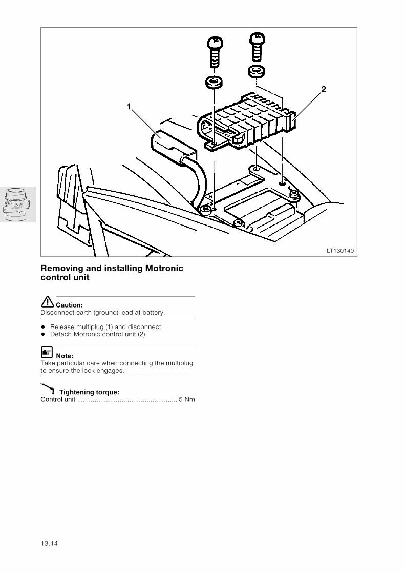
Removing and installing Motronic control unit
e Caution:Disconnect earth (ground) lead at battery!
• Release multiplug (1) and disconnect.• Detach Motronic control unit (2).
L Note:Take particular care when connecting the multiplug to ensure the lock engages.
X Tightening torque:Control unit .................................................... 5 Nm
LT130140
2
1
13.14
16
Contents Page
16 Fuel tank and lines
Technical data ................................................................................................................................ 3
Removing and installing fuel tank .......................................................................................5
Removing and installing fuel filter ......................................................................................6
Removing and installing fuel level sensor ......................................................................7
Removing and installing fuel pump ....................................................................................8
Checking fuel pump pressure ...............................................................................................9
16.1

16.2
16
Technical data K 1100 LT K 1100 RS
Fuel tank
Tank capacity l (Imp.gal) 22 (4.84)
incl. reserve capacity l (Imp.gal) 5 (1.1)
Fuel pump
Type Roller-cell pump
Make Bosch
Operating voltage V 12
Fuel pressure bar (psi) 2.5 (36.26)
Delivery rate l/h (gal/h) 45 (9.9)
16.3

16.4
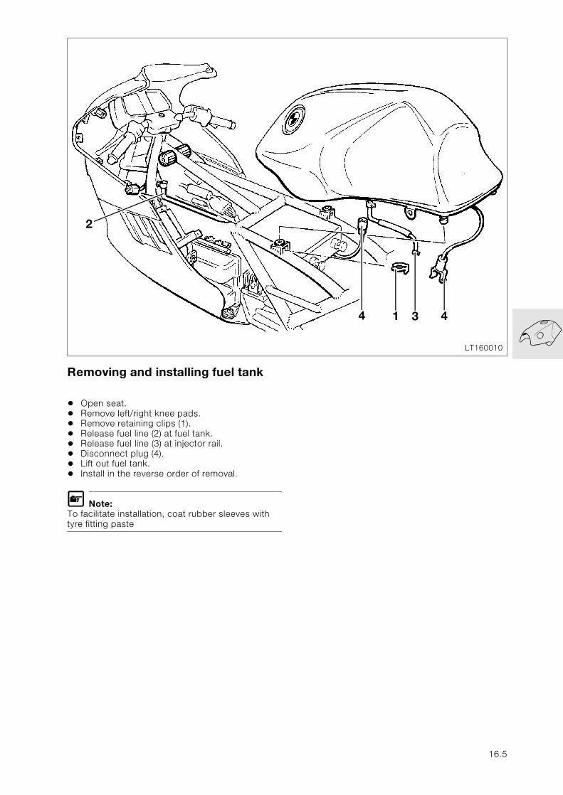
Removing and installing fuel tank
• Open seat.• Remove left/right knee pads.• Remove retaining clips (1).• Release fuel line (2) at fuel tank.• Release fuel line (3) at injector rail.• Disconnect plug (4).• Lift out fuel tank.• Install in the reverse order of removal.
L Note:To facilitate installation, coat rubber sleeves with tyre fitting paste
LT160010
2
4 1 43
16.5
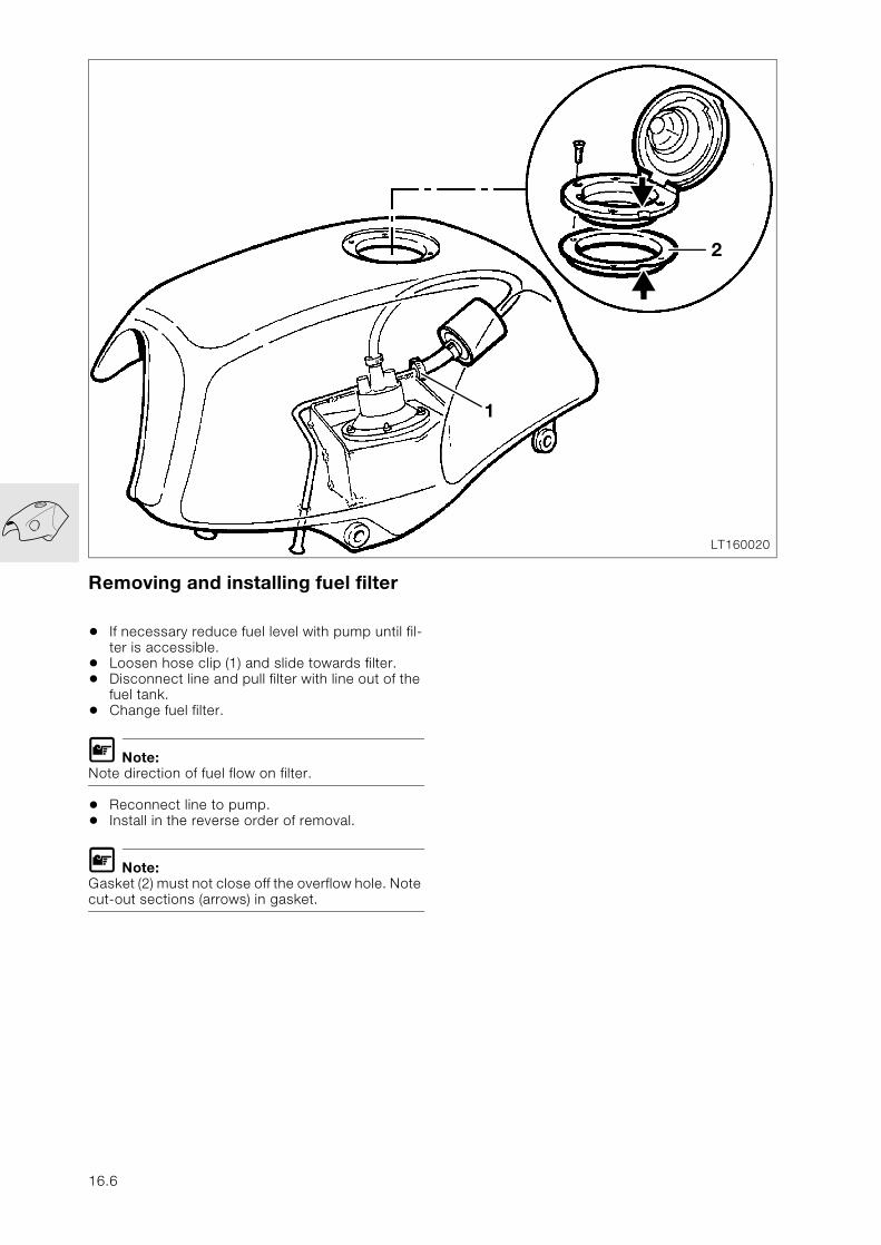
Removing and installing fuel filter
• If necessary reduce fuel level with pump until fil-ter is accessible.
• Loosen hose clip (1) and slide towards filter.• Disconnect line and pull filter with line out of the
fuel tank.• Change fuel filter.
L Note:Note direction of fuel flow on filter.
• Reconnect line to pump. • Install in the reverse order of removal.
L Note:Gasket (2) must not close off the overflow hole. Note cut-out sections (arrows) in gasket.
LT160020
1
2
16.6
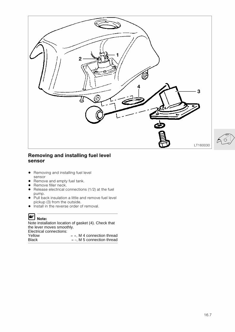
Removing and installing fuel level sensor
• Removing and installing fuel level sensor
• Remove and empty fuel tank.• Remove filler neck.• Release electrical connections (1/2) at the fuel
pump.• Pull back insulation a little and remove fuel level
pickup (3) from the outside.• Install in the reverse order of removal.
L Note:Note installation location of gasket (4). Check that the lever moves smoothly. Electrical connections:Yellow = +, M 4 connection threadBlack = –, M 5 connection thread
LT160030
2
34
1
16.7
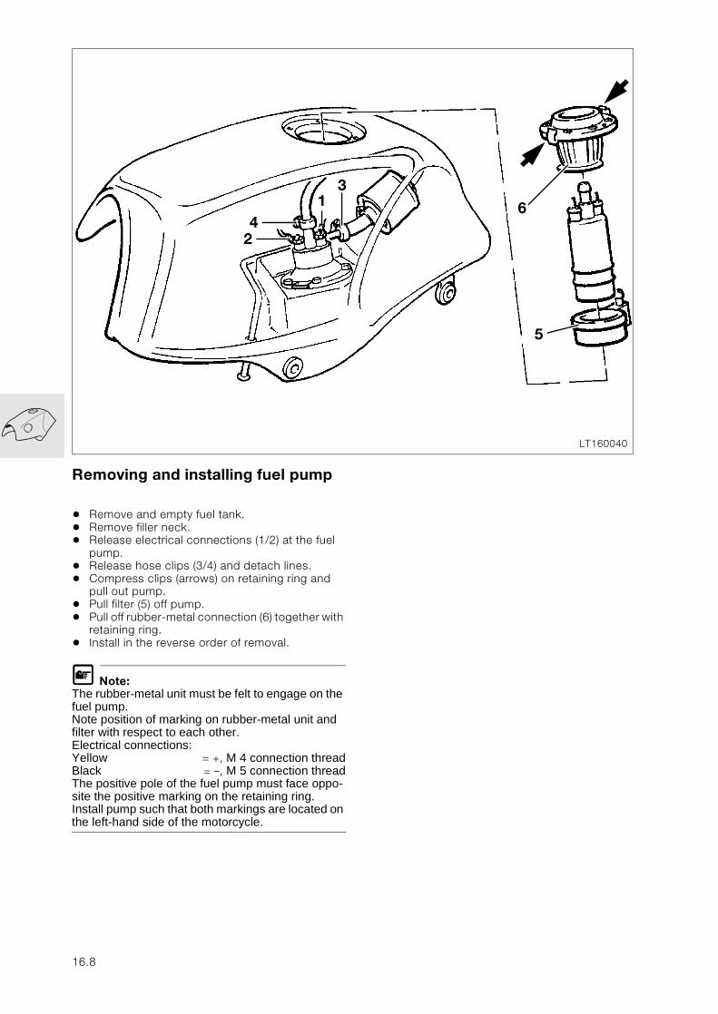
Removing and installing fuel pump
• Remove and empty fuel tank.• Remove filler neck.• Release electrical connections (1/2) at the fuel
pump.• Release hose clips (3/4) and detach lines.• Compress clips (arrows) on retaining ring and
pull out pump.• Pull filter (5) off pump.• Pull off rubber-metal connection (6) together with
retaining ring.• Install in the reverse order of removal.
L Note:The rubber-metal unit must be felt to engage on the fuel pump.Note position of marking on rubber-metal unit and filter with respect to each other.Electrical connections:Yellow = +, M 4 connection threadBlack = –, M 5 connection threadThe positive pole of the fuel pump must face oppo-site the positive marking on the retaining ring.Install pump such that both markings are located on the left-hand side of the motorcycle.
LT160040
2
614
3
5
16.8
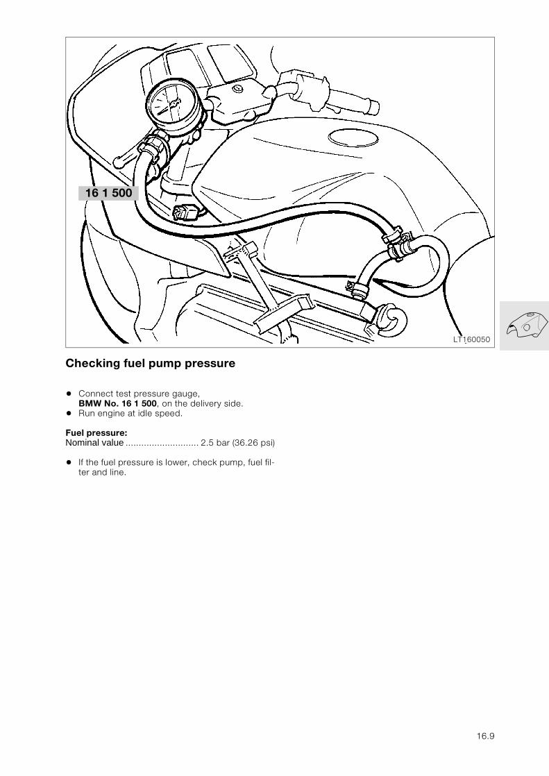
Checking fuel pump pressure
• Connect test pressure gauge, BMW No. 16 1 500, on the delivery side.
• Run engine at idle speed.
Fuel pressure:Nominal value ............................ 2.5 bar (36.26 psi)
• If the fuel pressure is lower, check pump, fuel fil-ter and line.
LT160050
16 1 500
16.9

16.10
17
Contents Page
17 Radiator
Technical data ................................................................................................................................ 3
Changing coolant .........................................................................................................................5
Draining coolant ...............................................................................................................................5
Filling with coolant ..........................................................................................................................5
Removing and installing thermostat ..................................................................................6
Checking thermostat .....................................................................................................................6
Removing and installing radiator .........................................................................................7
Removing and installing fan ...................................................................................................8
Removing and installing coolant hoses ...........................................................................9
Checking cooling system .......................................................................................................10
Checking cap for filler neck ......................................................................................................10
Checking coolant system for leaks .......................................................................................10
Troubleshooting ..........................................................................................................................11
17.1

17.2
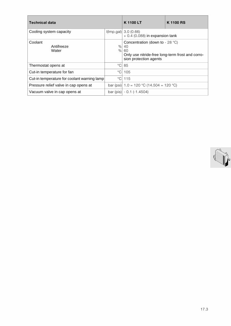
17
Technical data K 1100 LT K 1100 RS
Cooling system capacity l(Imp.gal) 3.0 (0.66)+ 0.4 (0.088) in expansion tank
CoolantAntifreezeWater
%%
Concentration (down to - 28 °C)4060Only use nitride-free long-term frost and corro-sion protection agents
Thermostat opens at °C 85
Cut-in temperature for fan °C 105
Cut-in temperature for coolant warning lamp °C 115
Pressure relief valve in cap opens at bar (psi) 1.0 = 120 °C (14.504 = 120 °C)
Vacuum valve in cap opens at bar (pis) - 0.1 (-1.4504)
17.3

17.4
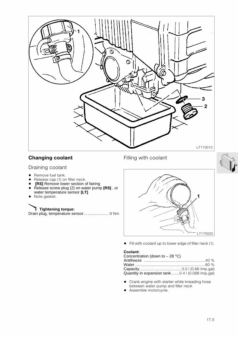
Changing coolant
Draining coolant
• Remove fuel tank.• Release cap (1) on filler neck. • [RS] Remove lower section of fairing • Release screw plug (2) on water pump [RS] , or
water temperature sensor [LT].• Note gasket.
X Tightening torque:Drain plug, temperature sensor ...................... 9 Nm
Filling with coolant
• Fill with coolant up to lower edge of filler neck (1).
Coolant:Concentration (down to – 28 °C)Antifreeze ......................................................40 %Water ..............................................................60 %Capacity.....................................3.0 l (0.66 Imp.gal)Quantity in expansion tank.......0.4 l (0.088 Imp.gal)
• Crank engine with starter while kneading hose between water pump and filler neck
• Assemble motorcycle.
LT170010
1
32
LT170020
1
17.5
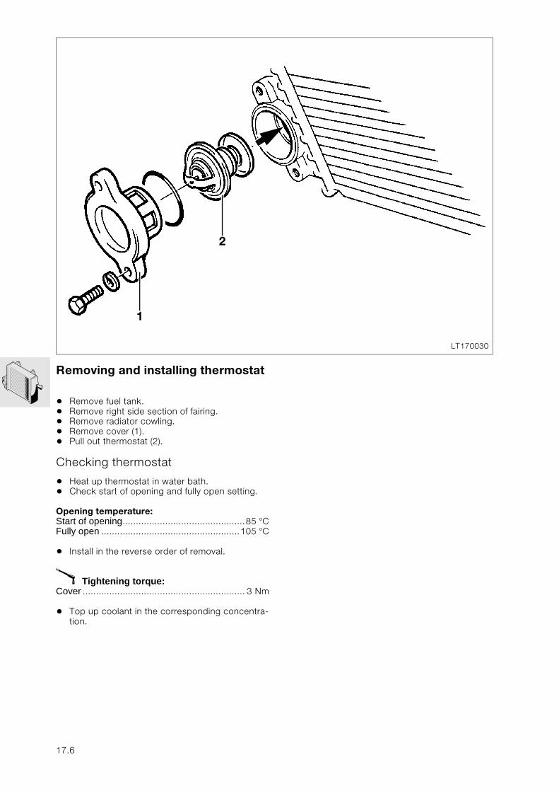
Removing and installing thermostat
• Remove fuel tank.• Remove right side section of fairing.• Remove radiator cowling.• Remove cover (1).• Pull out thermostat (2).
Checking thermostat
• Heat up thermostat in water bath.• Check start of opening and fully open setting.
Opening temperature:Start of opening..............................................85 °CFully open ....................................................105 °C
• Install in the reverse order of removal.
X Tightening torque:Cover ............................................................. 3 Nm
• Top up coolant in the corresponding concentra-tion.
LT170030
1
2
17.6
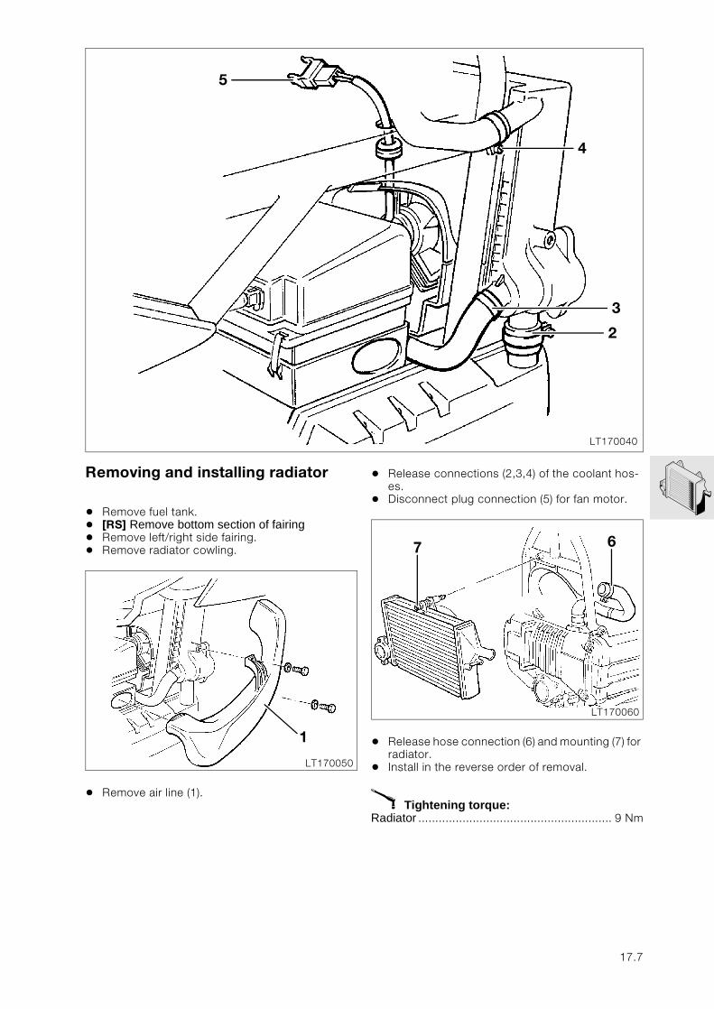
Removing and installing radiator
• Remove fuel tank.• [RS] Remove bottom section of fairing • Remove left/right side fairing.• Remove radiator cowling.
• Remove air line (1).
• Release connections (2,3,4) of the coolant hos-es.
• Disconnect plug connection (5) for fan motor.
• Release hose connection (6) and mounting (7) for radiator.
• Install in the reverse order of removal.
X Tightening torque:Radiator ......................................................... 9 Nm
LT170040
5
4
3
2
LT170050
1
LT170060
7 6
17.7
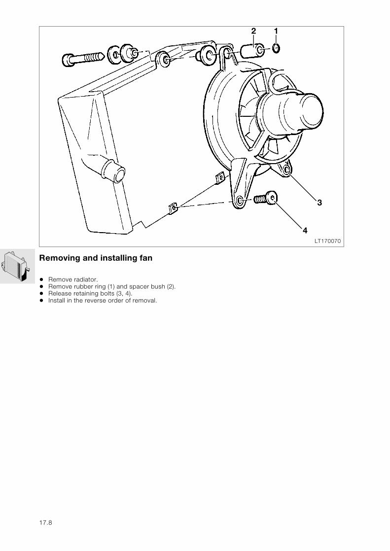
Removing and installing fan
• Remove radiator.• Remove rubber ring (1) and spacer bush (2).• Release retaining bolts (3, 4).• Install in the reverse order of removal.
LT170070
4
1
3
2
17.8
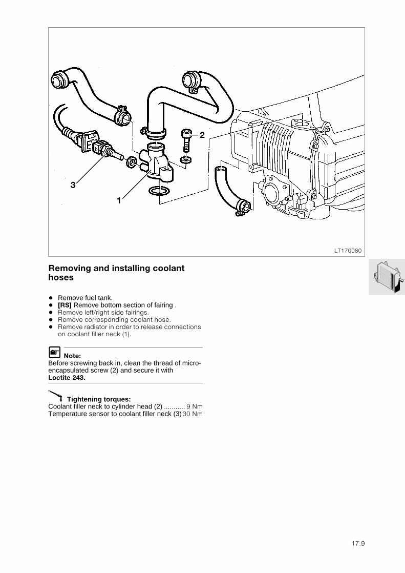
Removing and installing coolant hoses
• Remove fuel tank.• [RS] Remove bottom section of fairing .• Remove left/right side fairings.• Remove corresponding coolant hose.• Remove radiator in order to release connections
on coolant filler neck (1).
L Note:Before screwing back in, clean the thread of micro-encapsulated screw (2) and secure it with Loctite 243.
X Tightening torques:Coolant filler neck to cylinder head (2) ........... 9 NmTemperature sensor to coolant filler neck (3)30 Nm
LT170080
3
2
1
17.9
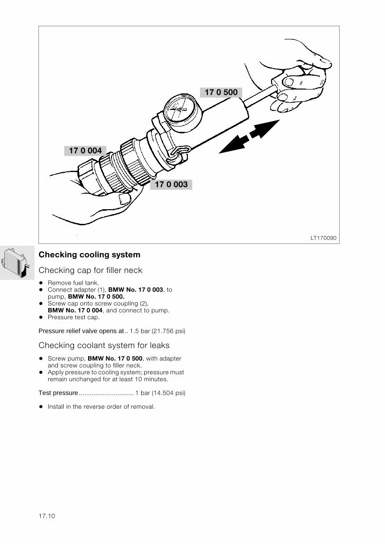
Checking cooling system
Checking cap for filler neck
• Remove fuel tank.• Connect adapter (1), BMW No. 17 0 003, to
pump, BMW No. 17 0 500. • Screw cap onto screw coupling (2),
BMW No. 17 0 004, and connect to pump.• Pressure test cap.
Pressure relief valve opens at .. 1.5 bar (21.756 psi)
Checking coolant system for leaks
• Screw pump, BMW No. 17 0 500, with adapter and screw coupling to filler neck.
• Apply pressure to cooling system; pressure must remain unchanged for at least 10 minutes.
Test pressure .............................. 1 bar (14.504 psi)
• Install in the reverse order of removal.
17 0 004
LT170090
17 0 003
17 0 500
17.10
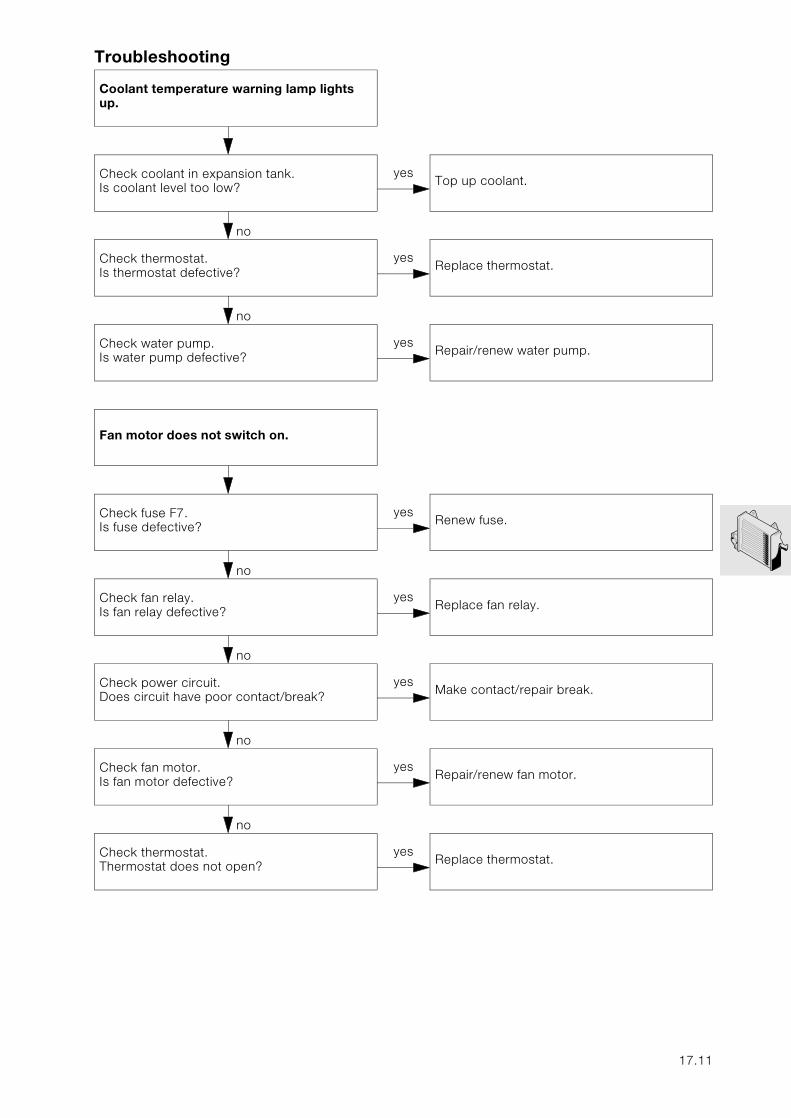
Troubleshooting
Coolant temperature warning lamp lights up.
no
Check coolant in expansion tank.Is coolant level too low?
yesTop up coolant.
no
Check thermostat.Is thermostat defective?
yesReplace thermostat.
no
Check water pump.Is water pump defective?
yesRepair/renew water pump.
Fan motor does not switch on.
no
Check fuse F7.Is fuse defective?
yesRenew fuse.
no
Check fan relay.Is fan relay defective?
yesReplace fan relay.
no
Check power circuit.Does circuit have poor contact/break?
yesMake contact/repair break.
no
Check fan motor.Is fan motor defective?
yesRepair/renew fan motor.
no
Check thermostat.Thermostat does not open?
yesReplace thermostat.
17.11
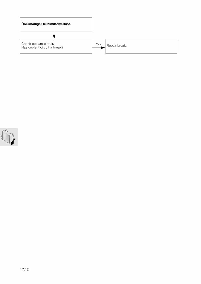
Übermäßiger Kühlmittelverlust.
no
Check coolant circuit.Has coolant circuit a break?
yesRepair break.
17.12
18
Contents Page
18 Exhaust system
Removing and installing exhaust system ........................................................................3
Removing and installing oxygen sensor ..........................................................................4
18.1

18.2
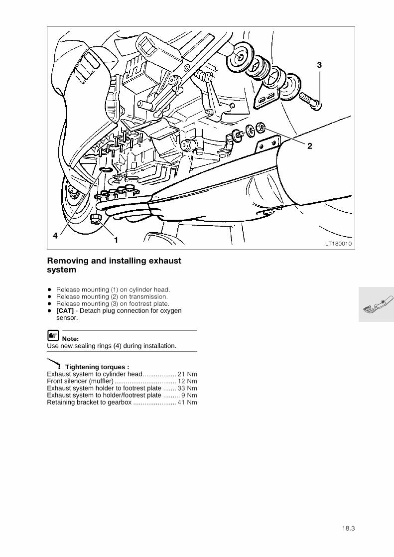
18
Removing and installing exhaust system
• Release mounting (1) on cylinder head.• Release mounting (2) on transmission.• Release mounting (3) on footrest plate.• [CAT] - Detach plug connection for oxygen
sensor.
L Note:Use new sealing rings (4) during installation.
X Tightening torques :Exhaust system to cylinder head.................. 21 NmFront silencer (muffler) ................................. 12 NmExhaust system holder to footrest plate ....... 33 NmExhaust system to holder/footrest plate ......... 9 NmRetaining bracket to gearbox ....................... 41 Nm
LT1800104
2
3
1
18.3
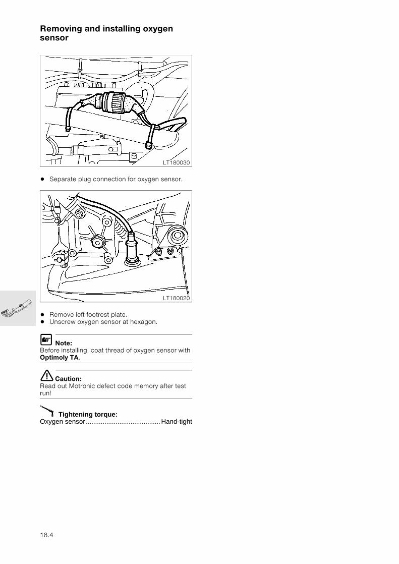
Removing and installing oxygen sensor
• Separate plug connection for oxygen sensor.
• Remove left footrest plate.• Unscrew oxygen sensor at hexagon.
L Note:Before installing, coat thread of oxygen sensor with Optimoly TA.
e Caution:Read out Motronic defect code memory after test run!
X Tightening torque:Oxygen sensor........................................Hand-tight
LT180030
LT180020
18.4
21
Contents Page
21 Clutch
Technical Data ............................................................................................................................... 3
Removing clutch ...........................................................................................................................5
Removing clutch housing ........................................................................................................7
Installing clutch housing ..........................................................................................................8
Installing clutch .............................................................................................................................9
Adjusting clutch clearance ...................................................................................................11
Removing and installing clutch thrust bearing ..........................................................12
Removing and installing clutch control rod .................................................................13
Removing and installing clutch release lever .............................................................14
Troubleshooting ..........................................................................................................................15
21.1

21.2
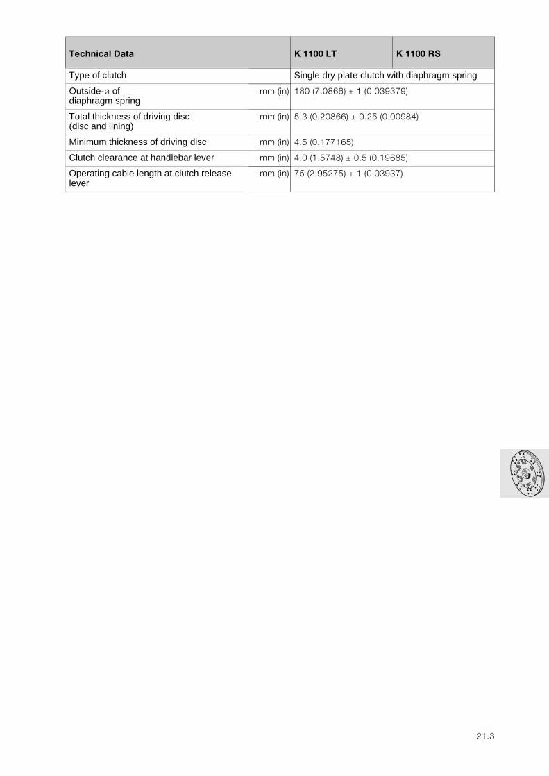
21
Technical Data K 1100 LT K 1100 RS
Type of clutch Single dry plate clutch with diaphragm spring
Outside-ø of diaphragm spring
mm (in) 180 (7.0866) ± 1 (0.039379)
Total thickness of driving disc(disc and lining)
mm (in) 5.3 (0.20866) ± 0.25 (0.00984)
Minimum thickness of driving disc mm (in) 4.5 (0.177165)
Clutch clearance at handlebar lever mm (in) 4.0 (1.5748) ± 0.5 (0.19685)
Operating cable length at clutch release lever
mm (in) 75 (2.95275) ± 1 (0.03937)
21.3

21.4
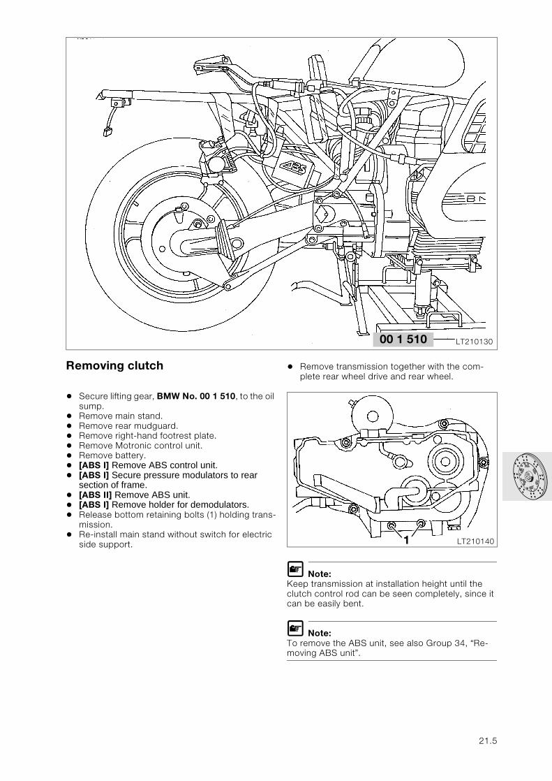
Removing clutch
• Secure lifting gear, BMW No. 00 1 510, to the oil sump.
• Remove main stand.• Remove rear mudguard.• Remove right-hand footrest plate.• Remove Motronic control unit.• Remove battery.• [ABS I] Remove ABS control unit.• [ABS I] Secure pressure modulators to rear
section of frame. • [ABS II] Remove ABS unit. • [ABS I] Remove holder for demodulators.• Release bottom retaining bolts (1) holding trans-
mission.• Re-install main stand without switch for electric
side support.
• Remove transmission together with the com-plete rear wheel drive and rear wheel.
L Note:Keep transmission at installation height until the clutch control rod can be seen completely, since it can be easily bent.
L Note:To remove the ABS unit, see also Group 34, “Re-moving ABS unit”.
LT21013000 1 510
LT2101401
21.5
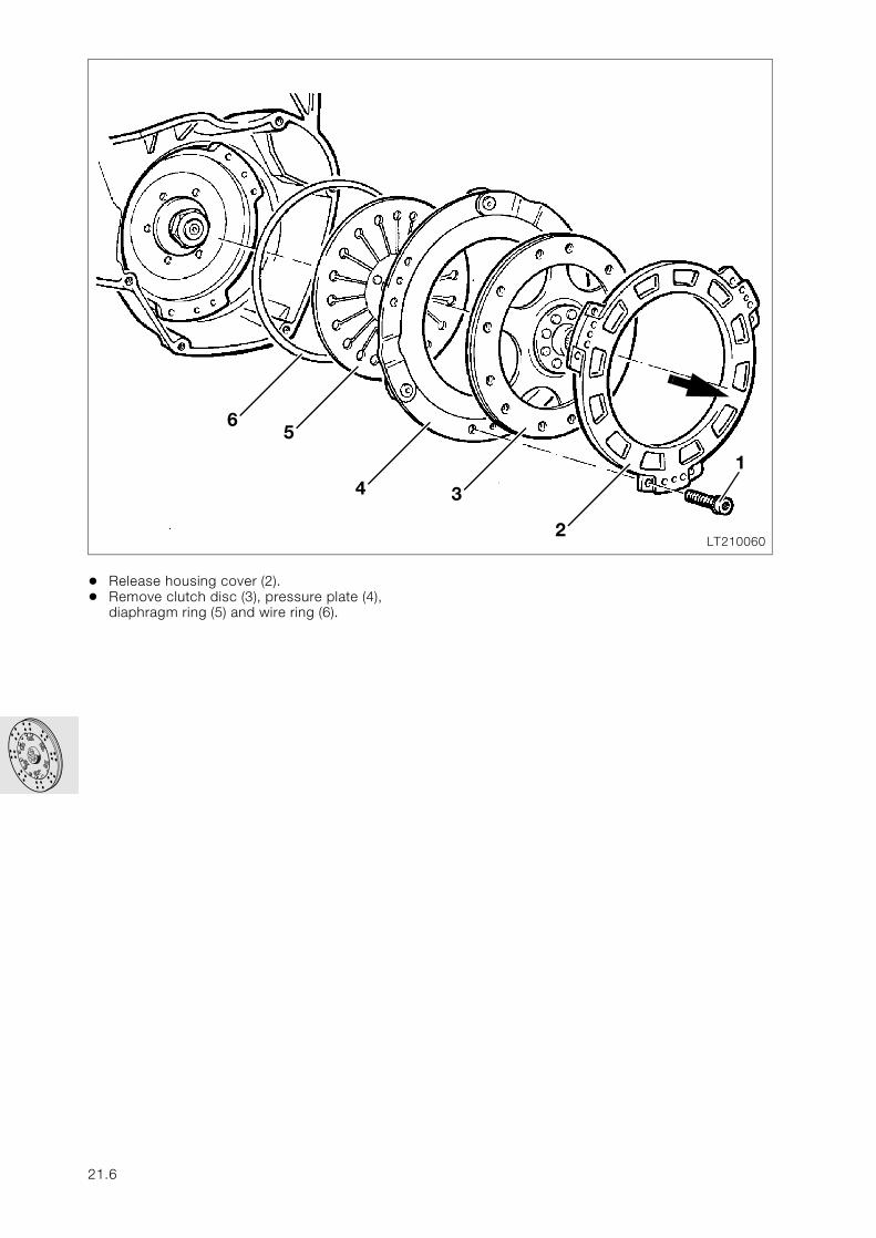
• Release housing cover (2).• Remove clutch disc (3), pressure plate (4),
diaphragm ring (5) and wire ring (6).
LT210060
65
4
2
3
1
21.6
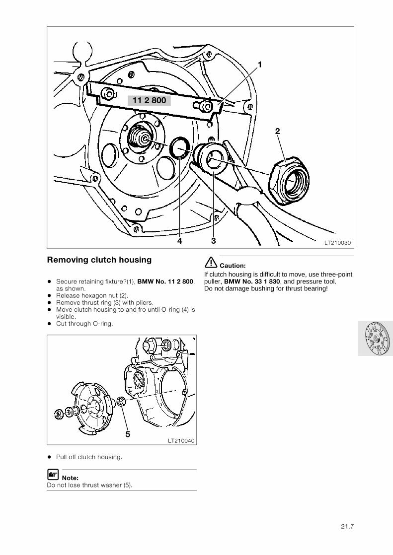
Removing clutch housing
• Secure retaining fixture?(1), BMW No. 11 2 800, as shown.
• Release hexagon nut (2).• Remove thrust ring (3) with pliers.• Move clutch housing to and fro until O-ring (4) is
visible.• Cut through O-ring.
• Pull off clutch housing.
L Note:Do not lose thrust washer (5).
e Caution:If clutch housing is difficult to move, use three-point puller, BMW No. 33 1 830, and pressure tool.Do not damage bushing for thrust bearing!
11 2 800
LT2100304
2
3
1
LT2100405
21.7
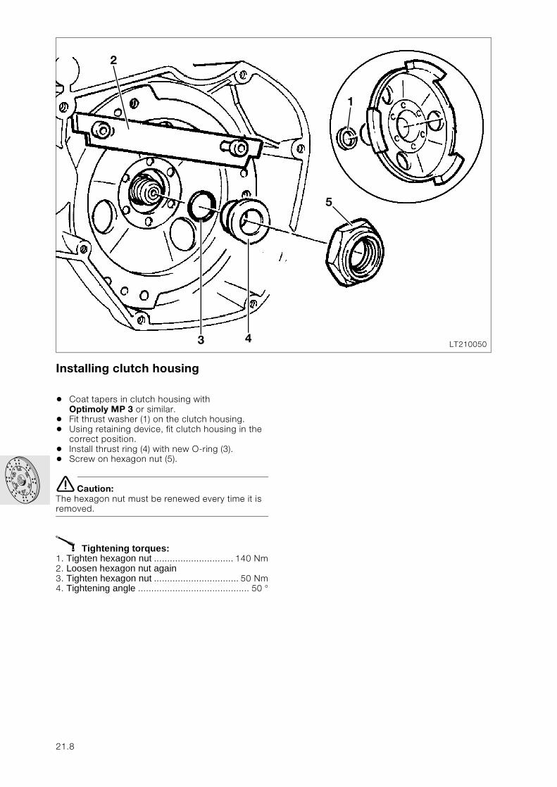
Installing clutch housing
• Coat tapers in clutch housing with Optimoly MP 3 or similar.
• Fit thrust washer (1) on the clutch housing.• Using retaining device, fit clutch housing in the
correct position.• Install thrust ring (4) with new O-ring (3).• Screw on hexagon nut (5).
e Caution:The hexagon nut must be renewed every time it is removed.
X Tightening torques:1. Tighten hexagon nut .............................. 140 Nm2. Loosen hexagon nut again3. Tighten hexagon nut ................................ 50 Nm4. Tightening angle .......................................... 50 °
LT2100503
1
5
4
2
21.8
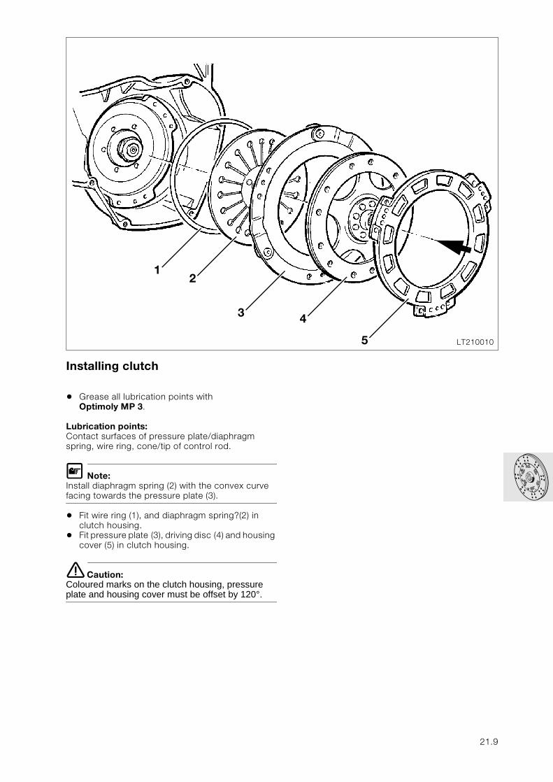
Installing clutch
• Grease all lubrication points with Optimoly MP 3.
Lubrication points:Contact surfaces of pressure plate/diaphragm spring, wire ring, cone/tip of control rod.
L Note:Install diaphragm spring (2) with the convex curve facing towards the pressure plate (3).
• Fit wire ring (1), and diaphragm spring?(2) in clutch housing.
• Fit pressure plate (3), driving disc (4) and housing cover (5) in clutch housing.
e Caution:Coloured marks on the clutch housing, pressure plate and housing cover must be offset by 120°.
LT210010
1
4
5
2
3
21.9
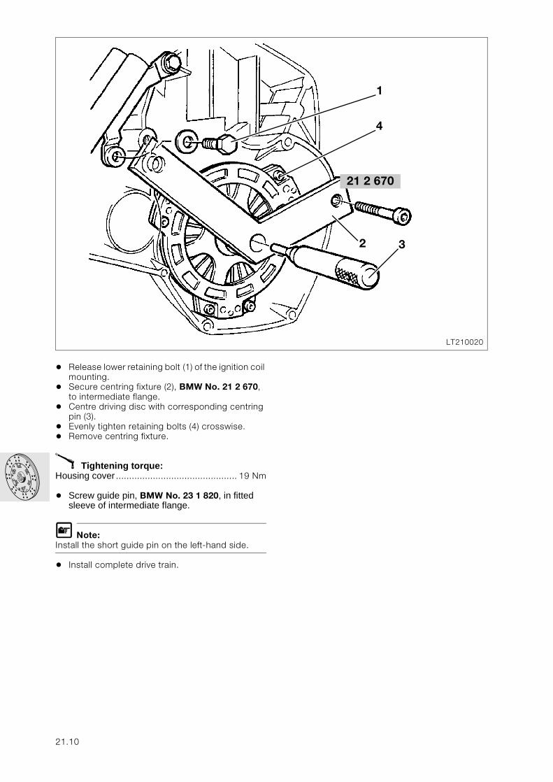
• Release lower retaining bolt (1) of the ignition coil mounting.
• Secure centring fixture (2), BMW No. 21 2 670, to intermediate flange.
• Centre driving disc with corresponding centring pin (3).
• Evenly tighten retaining bolts (4) crosswise.• Remove centring fixture.
X Tightening torque:Housing cover .............................................. 19 Nm
• Screw guide pin, BMW No. 23 1 820, in fitted sleeve of intermediate flange.
L Note:Install the short guide pin on the left-hand side.
• Install complete drive train.
LT210020
1
4
3
21 2 670
2
21.10
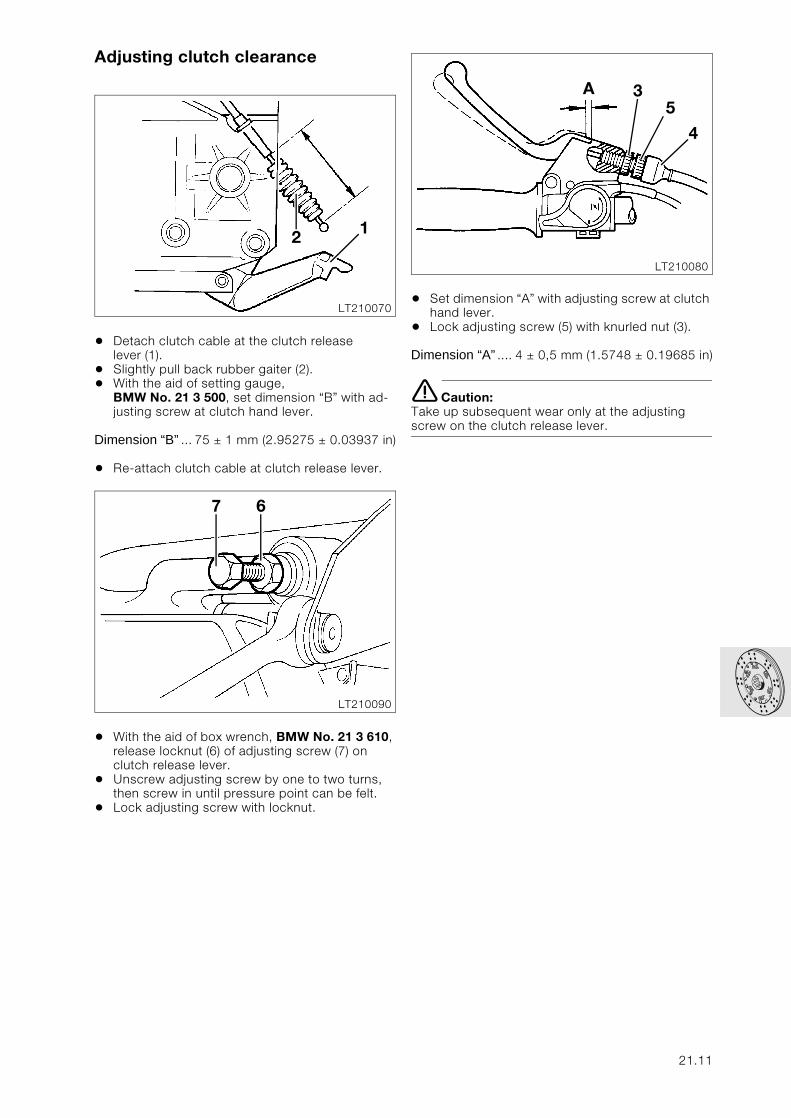
Adjusting clutch clearance
• Detach clutch cable at the clutch release lever (1).
• Slightly pull back rubber gaiter (2).• With the aid of setting gauge,
BMW No. 21 3 500, set dimension “B” with ad-justing screw at clutch hand lever.
Dimension “B” ... 75 ± 1 mm (2.95275 ± 0.03937 in)
• Re-attach clutch cable at clutch release lever.
• With the aid of box wrench, BMW No. 21 3 610, release locknut (6) of adjusting screw (7) on clutch release lever.
• Unscrew adjusting screw by one to two turns, then screw in until pressure point can be felt.
• Lock adjusting screw with locknut.
• Set dimension “A” with adjusting screw at clutch hand lever.
• Lock adjusting screw (5) with knurled nut (3).
Dimension “A” .... 4 ± 0,5 mm (1.5748 ± 0.19685 in)
e Caution:Take up subsequent wear only at the adjusting screw on the clutch release lever.
LT210070
2 1
LT210090
7 6
LT210080
3A5
4
21.11
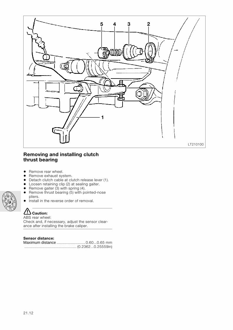
Removing and installing clutch thrust bearing
• Remove rear wheel.• Remove exhaust system.• Detach clutch cable at clutch release lever (1). • Loosen retaining clip (2) at sealing gaiter.• Remove gaiter (3) with spring (4).• Remove thrust bearing (5) with pointed-nose
pliers.• Install in the reverse order of removal.
e Caution:ABS rear wheel:Check and, if necessary, adjust the sensor clear-ance after installing the brake caliper.
Sensor distance:Maximum distance ..........................0.60...0.65 mm............................................... (0.2362...0.25559in)
LT210100
1
5 4 3 2
21.12
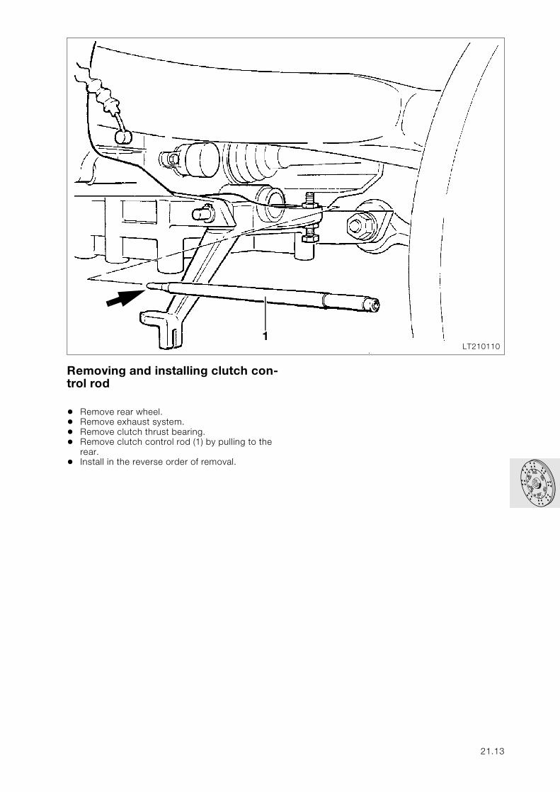
Removing and installing clutch con-trol rod
• Remove rear wheel.• Remove exhaust system.• Remove clutch thrust bearing.• Remove clutch control rod (1) by pulling to the
rear.• Install in the reverse order of removal.
LT2101101
21.13
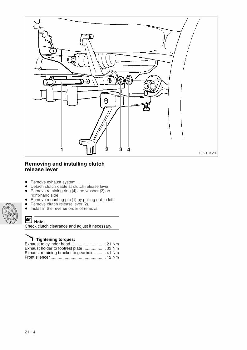
Removing and installing clutch release lever
• Remove exhaust system.• Detach clutch cable at clutch release lever.• Remove retaining ring (4) and washer (3) on
right-hand side.• Remove mounting pin (1) by pulling out to left.• Remove clutch release lever (2).• Install in the reverse order of removal.
L Note:Check clutch clearance and adjust if necessary.
X Tightening torques:Exhaust to cylinder head .............................. 21 NmExhaust holder to footrest plate.................... 33 NmExhaust retaining bracket to gearbox .......... 41 NmFront silencer ............................................... 12 Nm
LT2101201 3 42
21.14
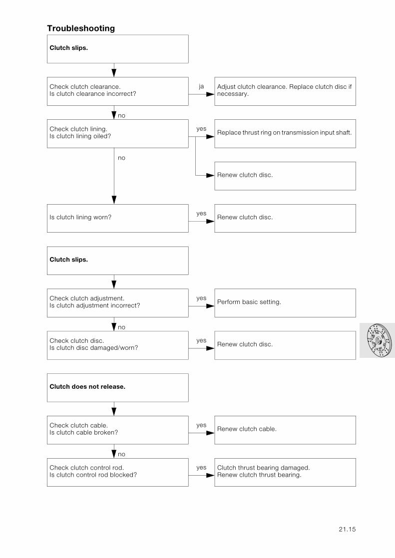
Troubleshooting
Clutch slips.
no
Check clutch clearance.Is clutch clearance incorrect?
ja Adjust clutch clearance. Replace clutch disc if necessary.
no
Check clutch lining.Is clutch lining oiled?
yesReplace thrust ring on transmission input shaft.
no
Renew clutch disc.
Is clutch lining worn?yes
Renew clutch disc.
Clutch slips.
no
Check clutch adjustment.Is clutch adjustment incorrect?
yesPerform basic setting.
no
Check clutch disc.Is clutch disc damaged/worn?
yesRenew clutch disc.
Clutch does not release.
no
Check clutch cable.Is clutch cable broken?
yesRenew clutch cable.
no
Check clutch control rod.Is clutch control rod blocked?
yes Clutch thrust bearing damaged.Renew clutch thrust bearing.
21.15
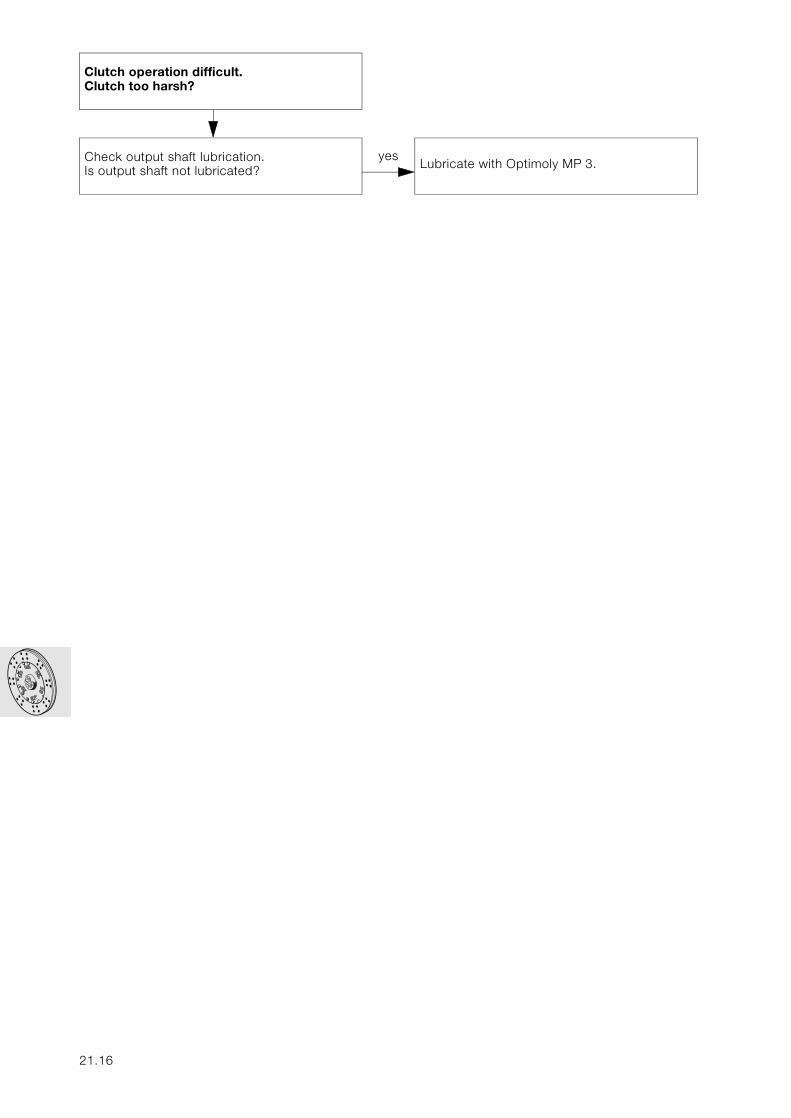
Clutch operation difficult.Clutch too harsh?
no
Check output shaft lubrication. Is output shaft not lubricated?
yesLubricate with Optimoly MP 3.
21.16
23
Contents Page
23 Gearbox
Technical Data ............................................................................................................................... 3
Removing transmission (gearbox) ......................................................................................5
Preparatory work .............................................................................................................................5
Removing starter .............................................................................................................................6
Removing bearing mount with main stand ..........................................................................7
Removing transmission (gearbox) ...........................................................................................8
Disassembling transmission (gearbox) ............................................................................9
Removing transmission cover. ..................................................................................................9
Disassembling/assembling transmission cover ..............................................................10Removing and installing bearing shell ................................................................................................10Removing and installing shaft sealing ring on input shaft ...................................................................10Removing and installing locking lever ................................................................................................10
Removing gear selector drum .................................................................................................11
Removing gearshift forks ...........................................................................................................11
Removing transmission shafts ................................................................................................12
Removing pawl ...............................................................................................................................12
Removing selector shaft ............................................................................................................13
Removing segment ......................................................................................................................13
Removing and installing shaft sealing ring on input shaft ...........................................13
Removing and installing shaft sealing ring for gear selector drum .........................14
Removing and installing bearing shell for taper roller bearing on input shaft ....14
Removing and installing ball bearing on intermediate shaft ......................................14
Disassembling and assembling input shaft .......................................................................15Disassembling input shaft .................................................................................................................15Assembling input shaft ......................................................................................................................15
23.1
Contents Page
Disassembling and assembling output shaft ....................................................................17Removing ball bearing .......................................................................................................................17Removing spur gears ........................................................................................................................18Installing spur gears ..........................................................................................................................19
Installing transmission shafts ...................................................................................................20
Installing gearshift forks .............................................................................................................20
Measuring distances between transmission shafts .......................................................21Measuring bearing distance of shafts ................................................................................................21Measuring transmission cover ...........................................................................................................22
Installing transmission cover ....................................................................................................24
Installing transmission (gearbox) .......................................................................................25
Installing bearing mount with main stand ...........................................................................26
Installing starter .............................................................................................................................27Re-assembling motorcycle ................................................................................................................28
23.2
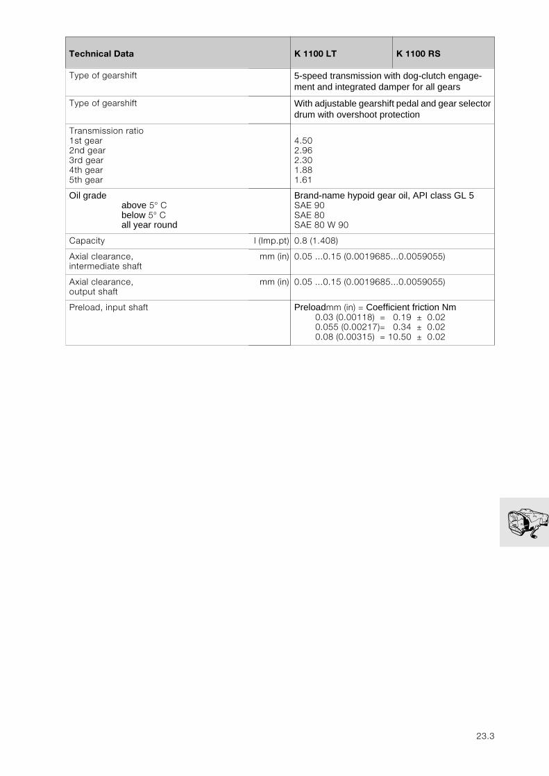
23
Technical Data K 1100 LT K 1100 RS
Type of gearshift 5-speed transmission with dog-clutch engage-ment and integrated damper for all gears
Type of gearshift With adjustable gearshift pedal and gear selector drum with overshoot protection
Transmission ratio1st gear2nd gear3rd gear4th gear5th gear
4.502.962.301.881.61
Oil gradeabove 5° Cbelow 5° Call year round
Brand-name hypoid gear oil, API class GL 5SAE 90SAE 80SAE 80 W 90
Capacity l (Imp.pt) 0.8 (1.408)
Axial clearance, intermediate shaft
mm (in) 0.05 ...0.15 (0.0019685...0.0059055)
Axial clearance, output shaft
mm (in) 0.05 ...0.15 (0.0019685...0.0059055)
Preload, input shaft Preloadmm (in) = Coefficient friction Nm0.03 (0.00118) = 0.19 ± 0.020.055 (0.00217)= 0.34 ± 0.020.08 (0.00315) = 10.50 ± 0.02
23.3

23.4
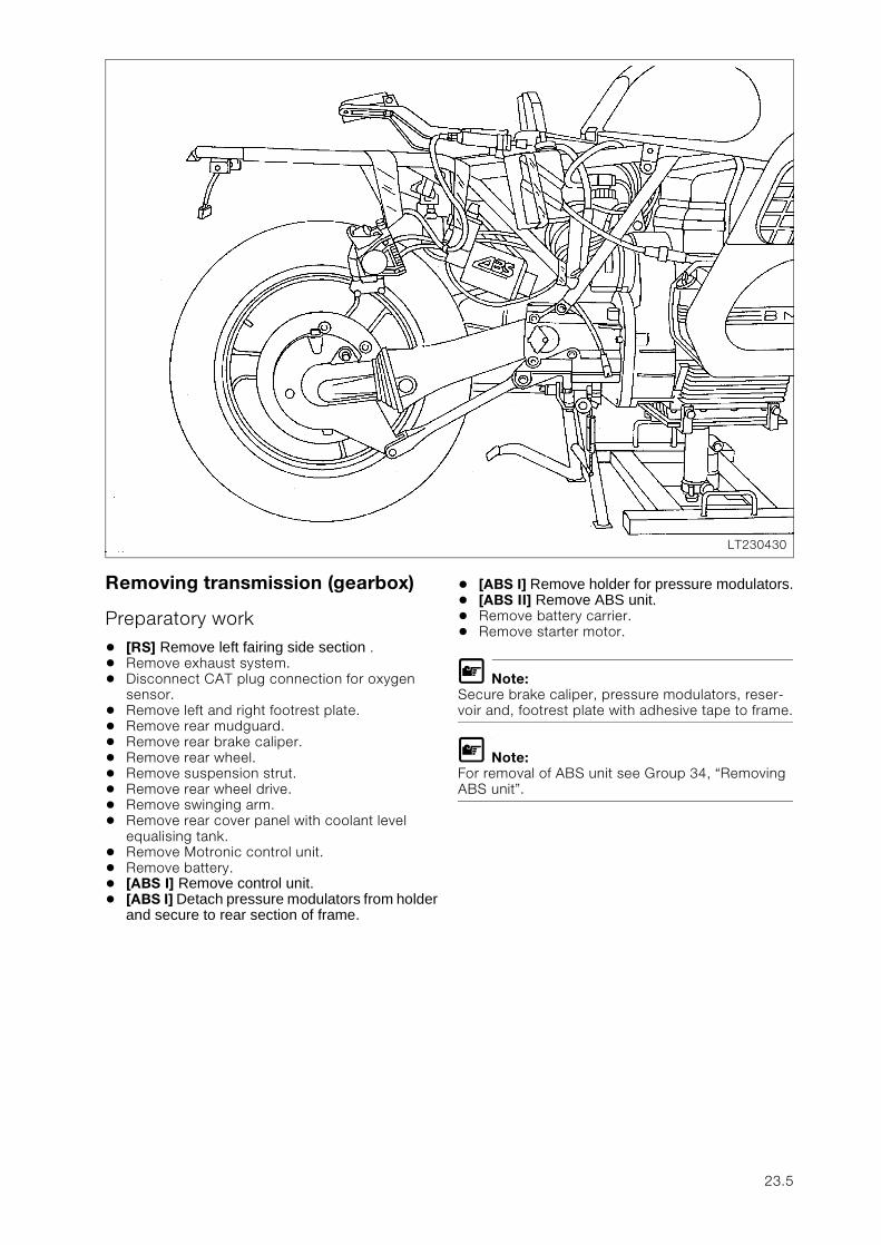
Removing transmission (gearbox)
Preparatory work
• [RS] Remove left fairing side section .• Remove exhaust system.• Disconnect CAT plug connection for oxygen
sensor.• Remove left and right footrest plate.• Remove rear mudguard.• Remove rear brake caliper.• Remove rear wheel.• Remove suspension strut.• Remove rear wheel drive.• Remove swinging arm.• Remove rear cover panel with coolant level
equalising tank.• Remove Motronic control unit.• Remove battery.• [ABS I] Remove control unit.• [ABS I] Detach pressure modulators from holder
and secure to rear section of frame.
• [ABS I] Remove holder for pressure modulators.• [ABS II] Remove ABS unit.• Remove battery carrier.• Remove starter motor.
L Note:Secure brake caliper, pressure modulators, reser-voir and, footrest plate with adhesive tape to frame.
L Note:For removal of ABS unit see Group 34, “Removing ABS unit”.
LT230430
23.5
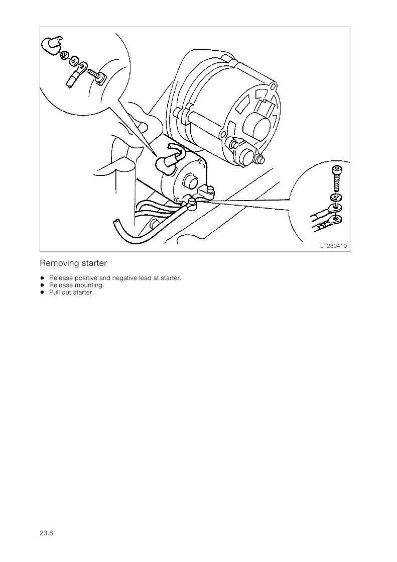
Removing starter
• Release positive and negative lead at starter.• Release mounting.• Pull out starter.
LT230410
23.6
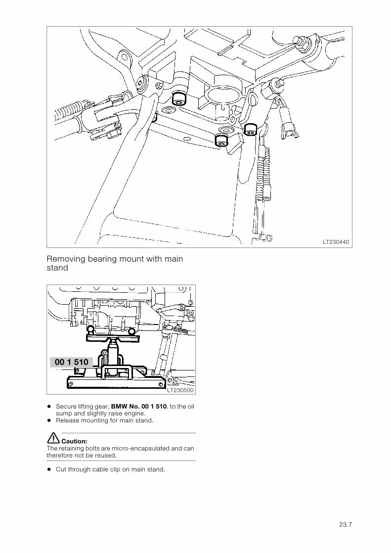
Removing bearing mount with main stand
• Secure lifting gear, BMW No. 00 1 510, to the oil sump and slightly raise engine.
• Release mounting for main stand.
e Caution:The retaining bolts are micro-encapsulated and can therefore not be reused.
• Cut through cable clip on main stand.
LT230440
00 1 510
LT230500
23.7
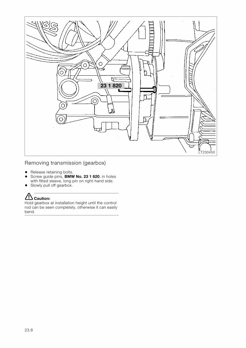
Removing transmission (gearbox)
• Release retaining bolts.• Screw guide pins, BMW No. 23 1 820, in holes
with fitted sleeve, long pin on right-hand side.• Slowly pull off gearbox.
e Caution:Hold gearbox at installation height until the control rod can be seen completely, otherwise it can easily bend.
23 1 820
LT230450
23.8
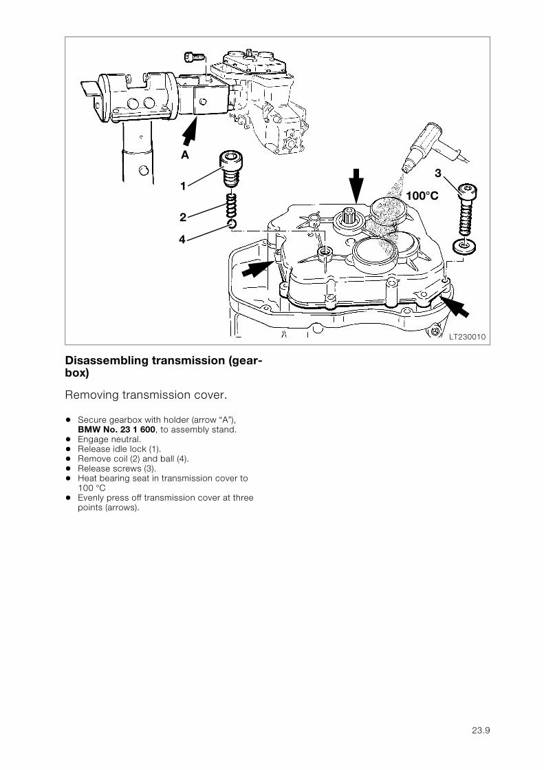
Disassembling transmission (gear-box)
Removing transmission cover.
• Secure gearbox with holder (arrow “A”), BMW No. 23 1 600, to assembly stand.
• Engage neutral.• Release idle lock (1).• Remove coil (2) and ball (4).• Release screws (3).• Heat bearing seat in transmission cover to
100 °C • Evenly press off transmission cover at three
points (arrows).
LT230010
13
2
4
A
100°C
23.9
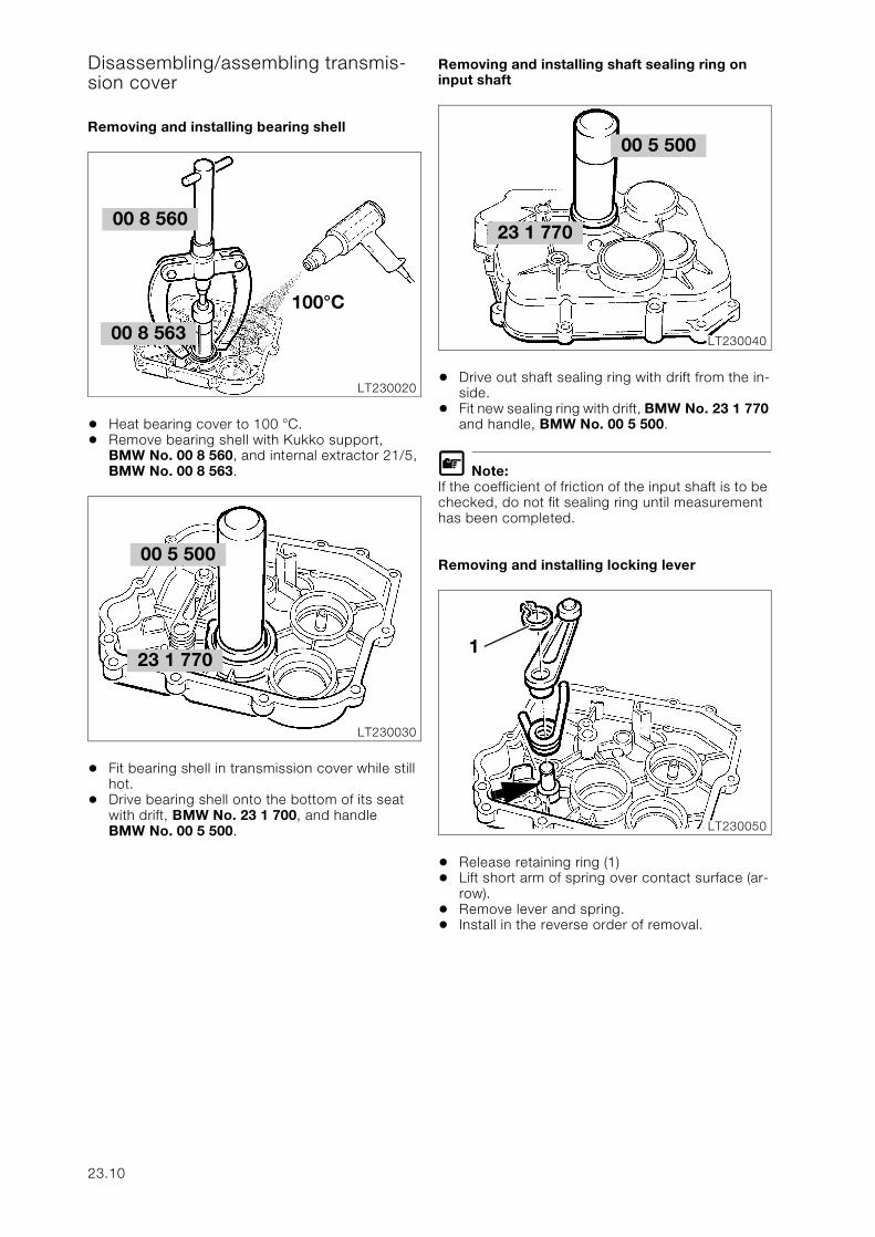
Disassembling/assembling transmis-sion cover
Removing and installing bearing shell
• Heat bearing cover to 100 °C. • Remove bearing shell with Kukko support,
BMW No. 00 8 560, and internal extractor 21/5, BMW No. 00 8 563.
• Fit bearing shell in transmission cover while still hot.
• Drive bearing shell onto the bottom of its seat with drift, BMW No. 23 1 700, and handle BMW No. 00 5 500.
Removing and installing shaft sealing ring on input shaft
• Drive out shaft sealing ring with drift from the in-side.
• Fit new sealing ring with drift, BMW No. 23 1 770 and handle, BMW No. 00 5 500.
L Note:If the coefficient of friction of the input shaft is to be checked, do not fit sealing ring until measurement has been completed.
Removing and installing locking lever
• Release retaining ring (1) • Lift short arm of spring over contact surface (ar-
row).• Remove lever and spring.• Install in the reverse order of removal.
LT230020
100°C
00 8 563
00 8 560
00 5 500
LT230030
23 1 770
23 1 770
LT230040
00 5 500
LT230050
1
23.10
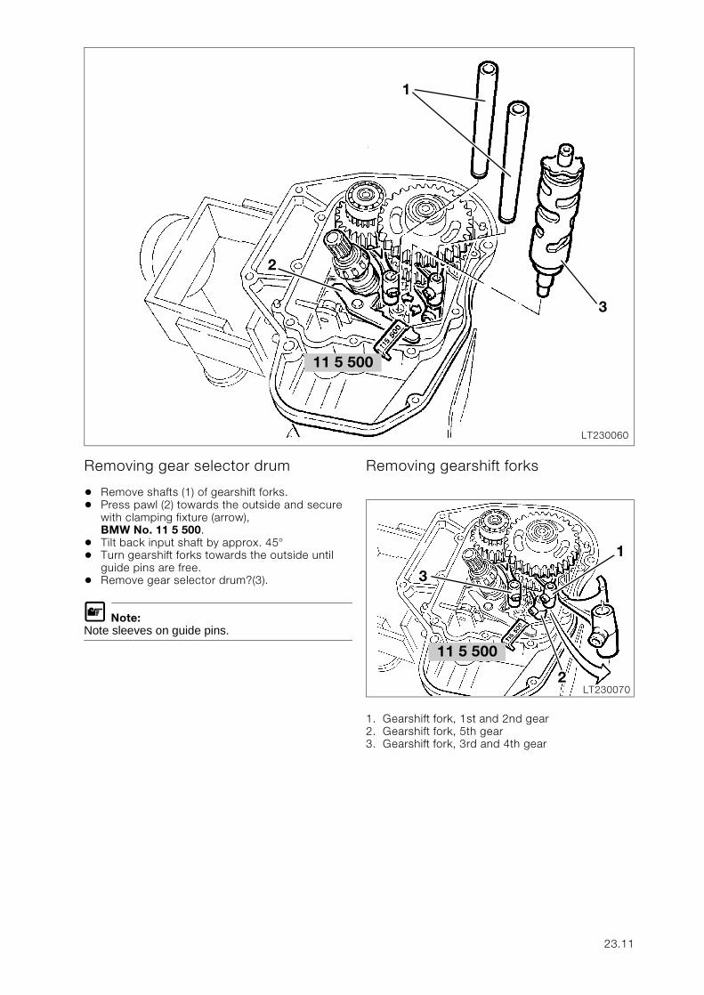
Removing gear selector drum
• Remove shafts (1) of gearshift forks.• Press pawl (2) towards the outside and secure
with clamping fixture (arrow), BMW No. 11 5 500.
• Tilt back input shaft by approx. 45° • Turn gearshift forks towards the outside until
guide pins are free.• Remove gear selector drum?(3).
L Note:Note sleeves on guide pins.
Removing gearshift forks
1. Gearshift fork, 1st and 2nd gear2. Gearshift fork, 5th gear3. Gearshift fork, 3rd and 4th gear
11 5 500
LT230060
1
3
2
11 5 500
LT230070
1
3
2
23.11
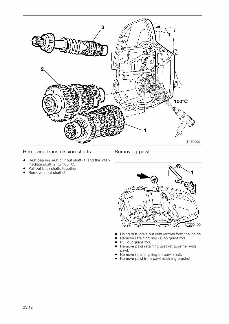
Removing transmission shafts
• Heat bearing seat of input shaft (1) and the inter-mediate shaft (2) to 100 °C.
• Pull out both shafts together.• Remove input shaft (3).
Removing pawl
• Using drift, drive out vent (arrow) from the inside.• Remove retaining ring (1) on guide rod.• Pull out guide rod.• Remove pawl retaining bracket together with
pawl.• Remove retaining ring on pawl shaft.• Remove pawl from pawl retaining bracket.
LT230090
2
1
3
100°C
LT230100
1
23.12
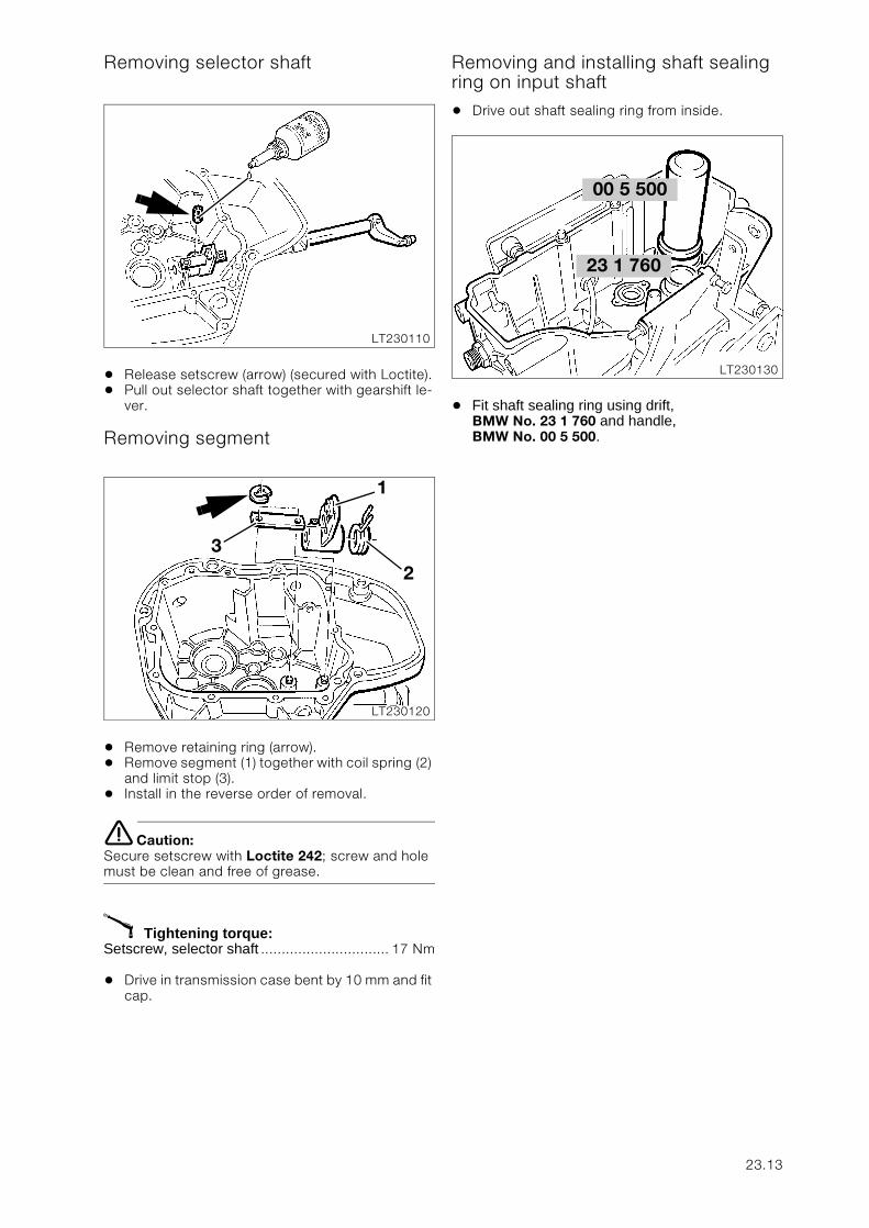
Removing selector shaft
• Release setscrew (arrow) (secured with Loctite).• Pull out selector shaft together with gearshift le-
ver.
Removing segment
• Remove retaining ring (arrow).• Remove segment (1) together with coil spring (2)
and limit stop (3).• Install in the reverse order of removal.
e Caution:Secure setscrew with Loctite 242; screw and hole must be clean and free of grease.
X Tightening torque:Setscrew, selector shaft ............................... 17 Nm
• Drive in transmission case bent by 10 mm and fit cap.
Removing and installing shaft sealing ring on input shaft
• Drive out shaft sealing ring from inside.
• Fit shaft sealing ring using drift, BMW No. 23 1 760 and handle, BMW No. 00 5 500.
LT230110
LT230120
1
23
23 1 760
LT230130
00 5 500
23.13
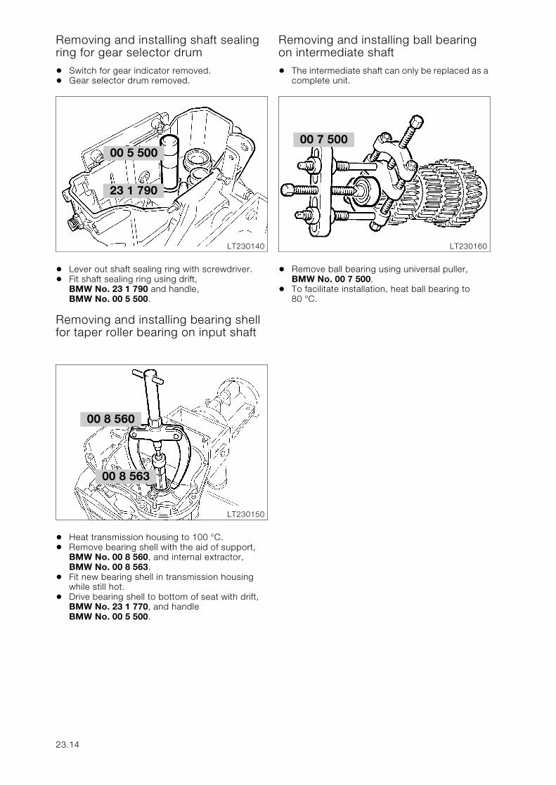
Removing and installing shaft sealing ring for gear selector drum
• Switch for gear indicator removed.• Gear selector drum removed.
• Lever out shaft sealing ring with screwdriver.• Fit shaft sealing ring using drift,
BMW No. 23 1 790 and handle, BMW No. 00 5 500.
Removing and installing bearing shell for taper roller bearing on input shaft
• Heat transmission housing to 100 °C.• Remove bearing shell with the aid of support,
BMW No. 00 8 560, and internal extractor, BMW No. 00 8 563.
• Fit new bearing shell in transmission housing while still hot.
• Drive bearing shell to bottom of seat with drift, BMW No. 23 1 770, and handle BMW No. 00 5 500.
Removing and installing ball bearing on intermediate shaft
• The intermediate shaft can only be replaced as a complete unit.
• Remove ball bearing using universal puller, BMW No. 00 7 500.
• To facilitate installation, heat ball bearing to 80 °C.
00 5 500
LT230140
23 1 790
00 8 560
LT230150
00 8 563
00 7 500
LT230160
23.14
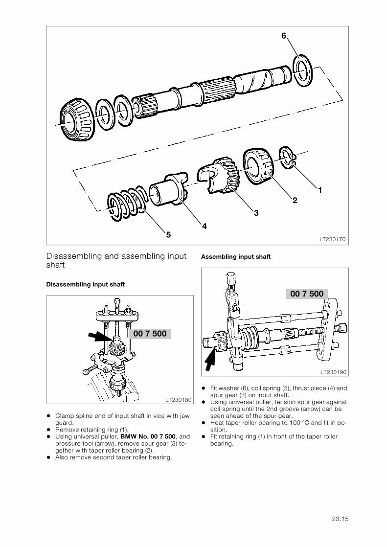
Disassembling and assembling input shaft
Disassembling input shaft
• Clamp spline end of input shaft in vice with jaw guard.
• Remove retaining ring (1).• Using universal puller, BMW No. 00 7 500, and
pressure tool (arrow), remove spur gear (3) to-gether with taper roller bearing (2).
• Also remove second taper roller bearing.
Assembling input shaft
• Fit washer (6), coil spring (5), thrust piece (4) and spur gear (3) on input shaft.
• Using universal puller, tension spur gear against coil spring until the 2nd groove (arrow) can be seen ahead of the spur gear.
• Heat taper roller bearing to 100 °C and fit in po-sition.
• Fit retaining ring (1) in front of the taper roller bearing.
LT2301705
6
4
3
21
00 7 500
LT230180
00 7 500
LT230190
23.15
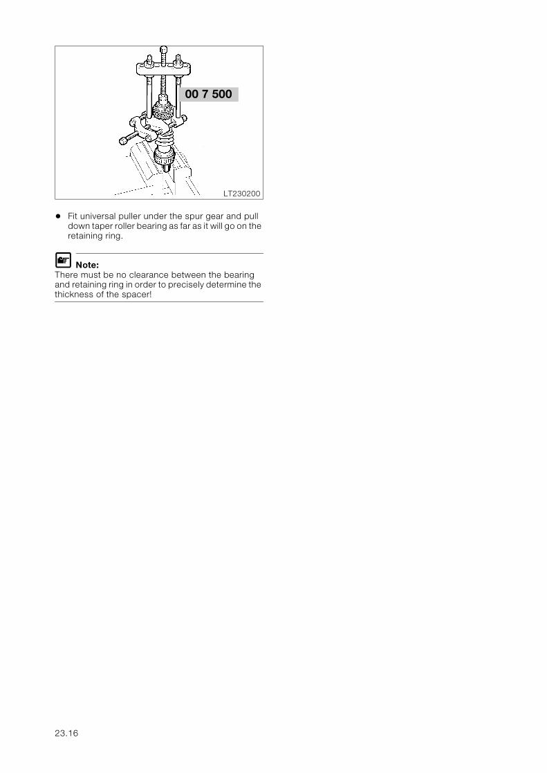
• Fit universal puller under the spur gear and pull down taper roller bearing as far as it will go on the retaining ring.
L Note:There must be no clearance between the bearing and retaining ring in order to precisely determine the thickness of the spacer!
00 7 500
LT230200
23.16
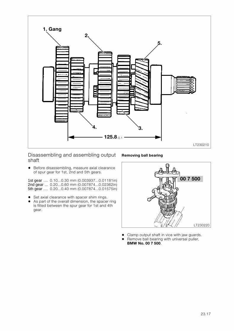
Disassembling and assembling output shaft
• Before disassembling, measure axial clearance of spur gear for 1st, 2nd and 5th gears.
1st gear .... 0.10...0.30 mm (0.003937...0.01181in)2nd gear ... 0.20...0.60 mm (0.007874...0.02362in)5th gear .... 0.20...0.40 mm (0.007874...0.01575in)
• Set axial clearance with spacer shim rings.• As part of the overall dimension, the spacer ring
is fitted between the spur gear for 1st and 4th gear.
Removing ball bearing
• Clamp output shaft in vice with jaw guards.• Remove ball bearing with universal puller,
BMW No. 00 7 500.
LT230210
4.
5.
3.
1. Gang2.
125.8-0.1
00 7 500
LT230220
23.17
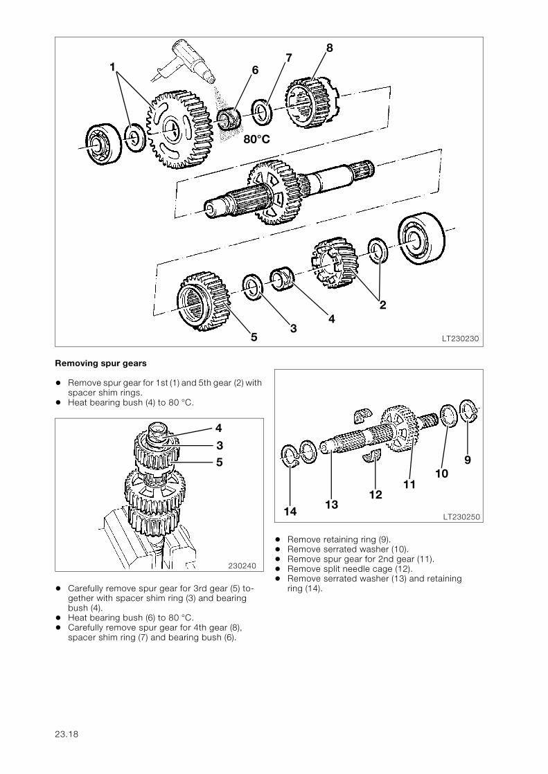
Removing spur gears
• Remove spur gear for 1st (1) and 5th gear (2) with spacer shim rings.
• Heat bearing bush (4) to 80 °C.
• Carefully remove spur gear for 3rd gear (5) to-gether with spacer shim ring (3) and bearing bush (4).
• Heat bearing bush (6) to 80 °C.• Carefully remove spur gear for 4th gear (8),
spacer shim ring (7) and bearing bush (6).
• Remove retaining ring (9).• Remove serrated washer (10).• Remove spur gear for 2nd gear (11).• Remove split needle cage (12).• Remove serrated washer (13) and retaining
ring (14).
LT230230
6
8
1
80°C
24
35
7
230240
4
35
LT23025014 1312
1110
9
23.18
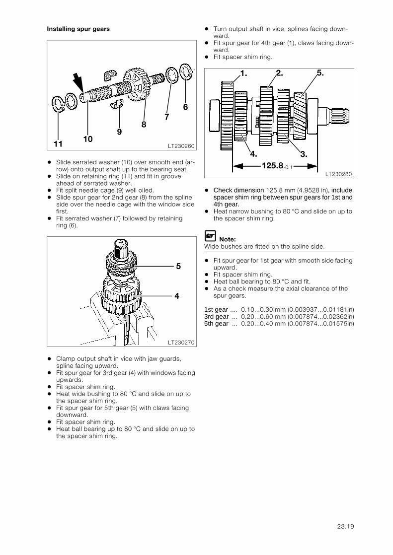
Installing spur gears
• Slide serrated washer (10) over smooth end (ar-row) onto output shaft up to the bearing seat.
• Slide on retaining ring (11) and fit in groove ahead of serrated washer.
• Fit split needle cage (9) well oiled.• Slide spur gear for 2nd gear (8) from the spline
side over the needle cage with the window side first.
• Fit serrated washer (7) followed by retaining ring (6).
• Clamp output shaft in vice with jaw guards, spline facing upward.
• Fit spur gear for 3rd gear (4) with windows facing upwards.
• Fit spacer shim ring.• Heat wide bushing to 80 °C and slide on up to
the spacer shim ring.• Fit spur gear for 5th gear (5) with claws facing
downward.• Fit spacer shim ring.• Heat ball bearing up to 80 °C and slide on up to
the spacer shim ring.
• Turn output shaft in vice, splines facing down-ward.
• Fit spur gear for 4th gear (1), claws facing down-ward.
• Fit spacer shim ring.
• Check dimension 125.8 mm (4.9528 in), include spacer shim ring between spur gears for 1st and 4th gear.
• Heat narrow bushing to 80 °C and slide on up to the spacer shim ring.
L Note:Wide bushes are fitted on the spline side.
• Fit spur gear for 1st gear with smooth side facing upward.
• Fit spacer shim ring.• Heat ball bearing to 80 °C and fit.• As a check measure the axial clearance of the
spur gears.
1st gear .... 0.10...0.30 mm (0.003937...0.01181in)3rd gear ... 0.20...0.60 mm (0.007874...0.02362in)5th gear ... 0.20...0.40 mm (0.007874...0.01575in)
LT23026011 109
87
6
LT230270
4
5
LT230280
4. 3.125.8-0.1
1. 2. 5.
23.19
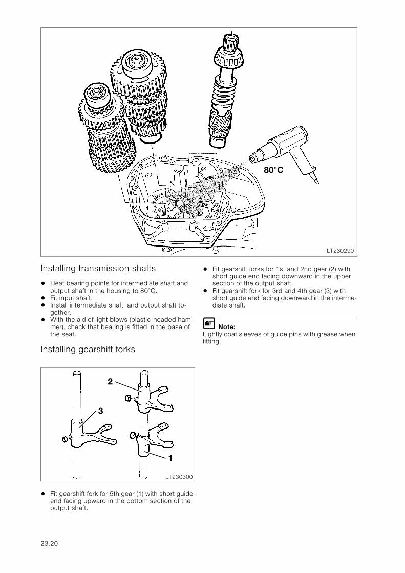
Installing transmission shafts
• Heat bearing points for intermediate shaft and output shaft in the housing to 80°C.
• Fit input shaft.• Install intermediate shaft and output shaft to-
gether.• With the aid of light blows (plastic-headed ham-
mer), check that bearing is fitted in the base of the seat.
Installing gearshift forks
• Fit gearshift fork for 5th gear (1) with short guide end facing upward in the bottom section of the output shaft.
• Fit gearshift forks for 1st and 2nd gear (2) with short guide end facing downward in the upper section of the output shaft.
• Fit gearshift fork for 3rd and 4th gear (3) with short guide end facing downward in the interme-diate shaft.
L Note:Lightly coat sleeves of guide pins with grease when fitting.
LT230290
80°C
LT230300
2
3
1
23.20
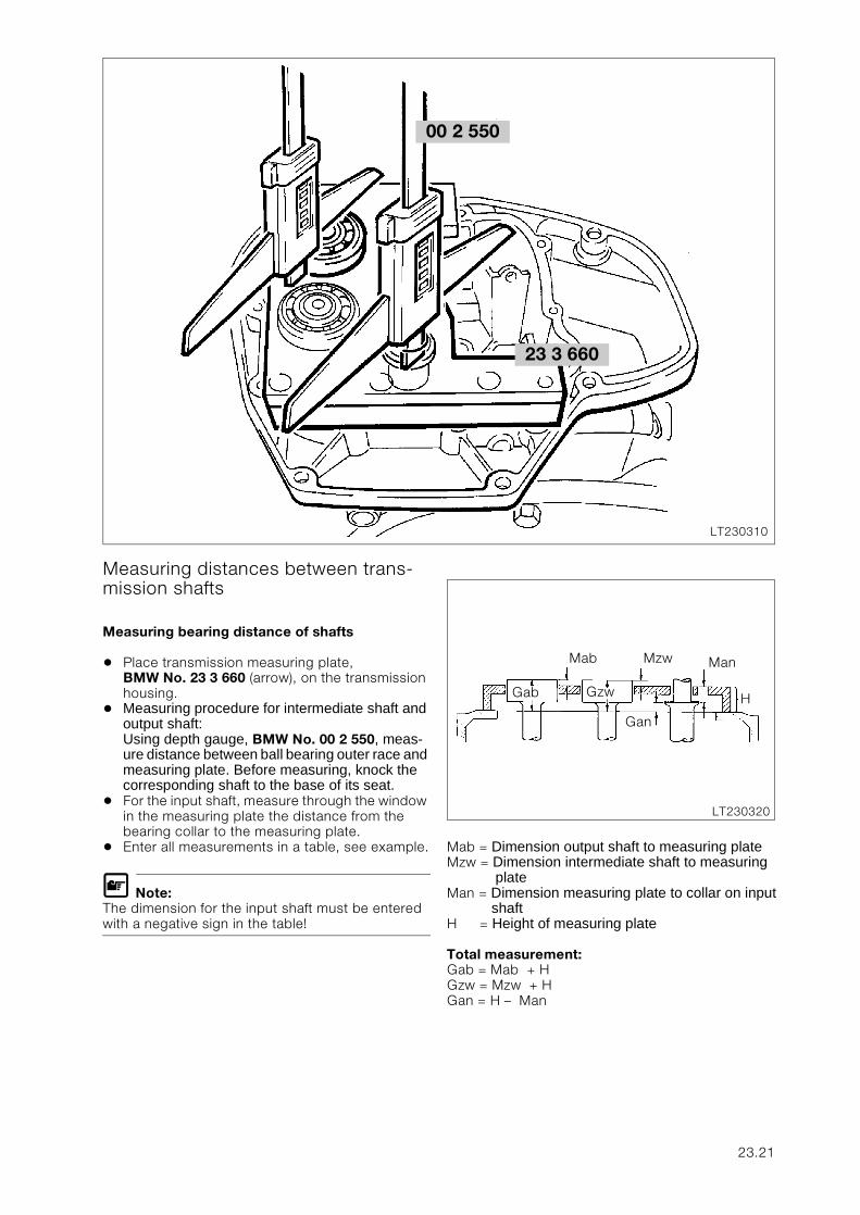
Measuring distances between trans-mission shafts
Measuring bearing distance of shafts
• Place transmission measuring plate, BMW No. 23 3 660 (arrow), on the transmission housing.
• Measuring procedure for intermediate shaft and output shaft:Using depth gauge, BMW No. 00 2 550, meas-ure distance between ball bearing outer race and measuring plate. Before measuring, knock the corresponding shaft to the base of its seat.
• For the input shaft, measure through the window in the measuring plate the distance from the bearing collar to the measuring plate.
• Enter all measurements in a table, see example.
L Note:The dimension for the input shaft must be entered with a negative sign in the table!
Mab = Dimension output shaft to measuring plateMzw = Dimension intermediate shaft to measuring
plateMan = Dimension measuring plate to collar on input
shaftH = Height of measuring plate
Total measurement:Gab = Mab + HGzw = Mzw + HGan = H – Man
23 3 660
LT230310
00 2 550
LT230320
Mab Mzw Man
Gab Gzw
Gan
H
23.21
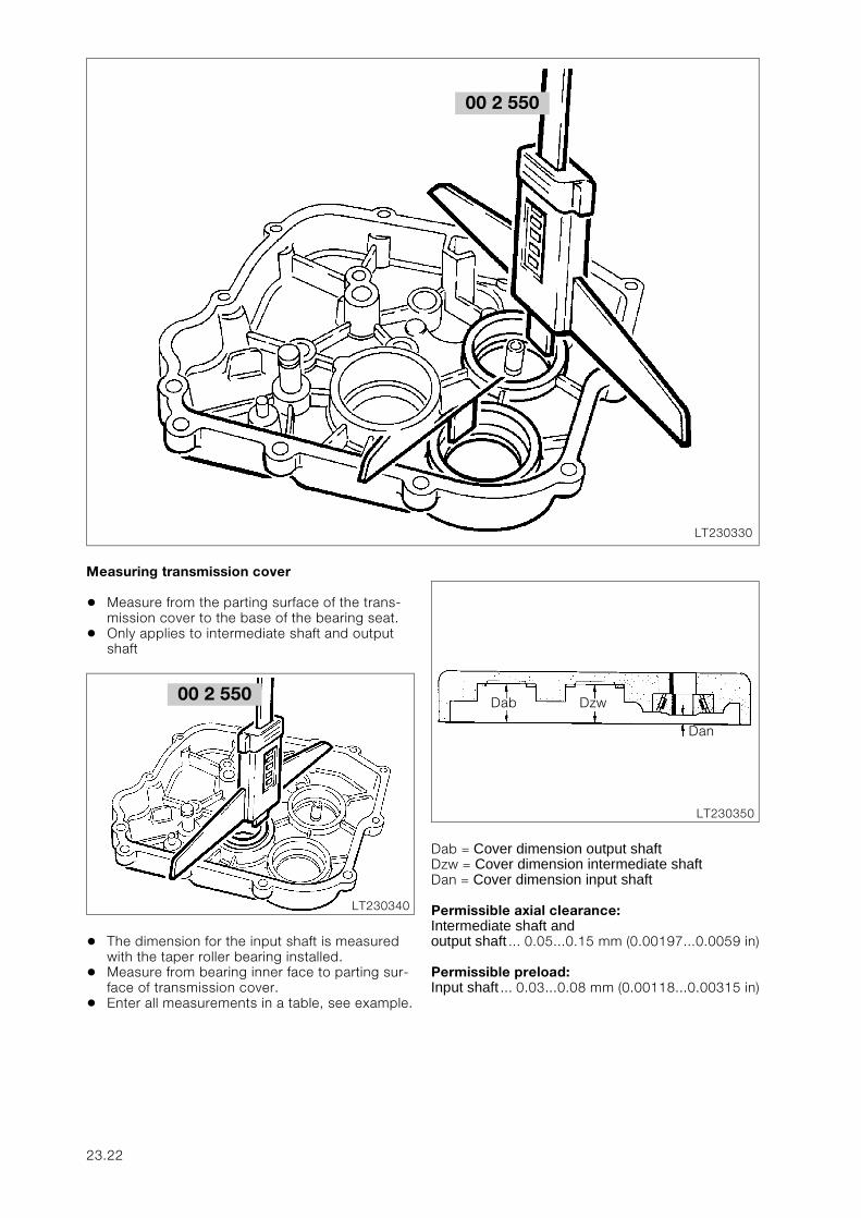
Measuring transmission cover
• Measure from the parting surface of the trans-mission cover to the base of the bearing seat.
• Only applies to intermediate shaft and output shaft
• The dimension for the input shaft is measured with the taper roller bearing installed.
• Measure from bearing inner face to parting sur-face of transmission cover.
• Enter all measurements in a table, see example.
Dab = Cover dimension output shaftDzw = Cover dimension intermediate shaftDan = Cover dimension input shaft
Permissible axial clearance:Intermediate shaft and output shaft ... 0.05...0.15 mm (0.00197...0.0059 in)
Permissible preload:Input shaft ... 0.03...0.08 mm (0.00118...0.00315 in)
00 2 550
LT230330
00 2 550
LT230340
LT230350
Dab Dzw
Dan
23.22
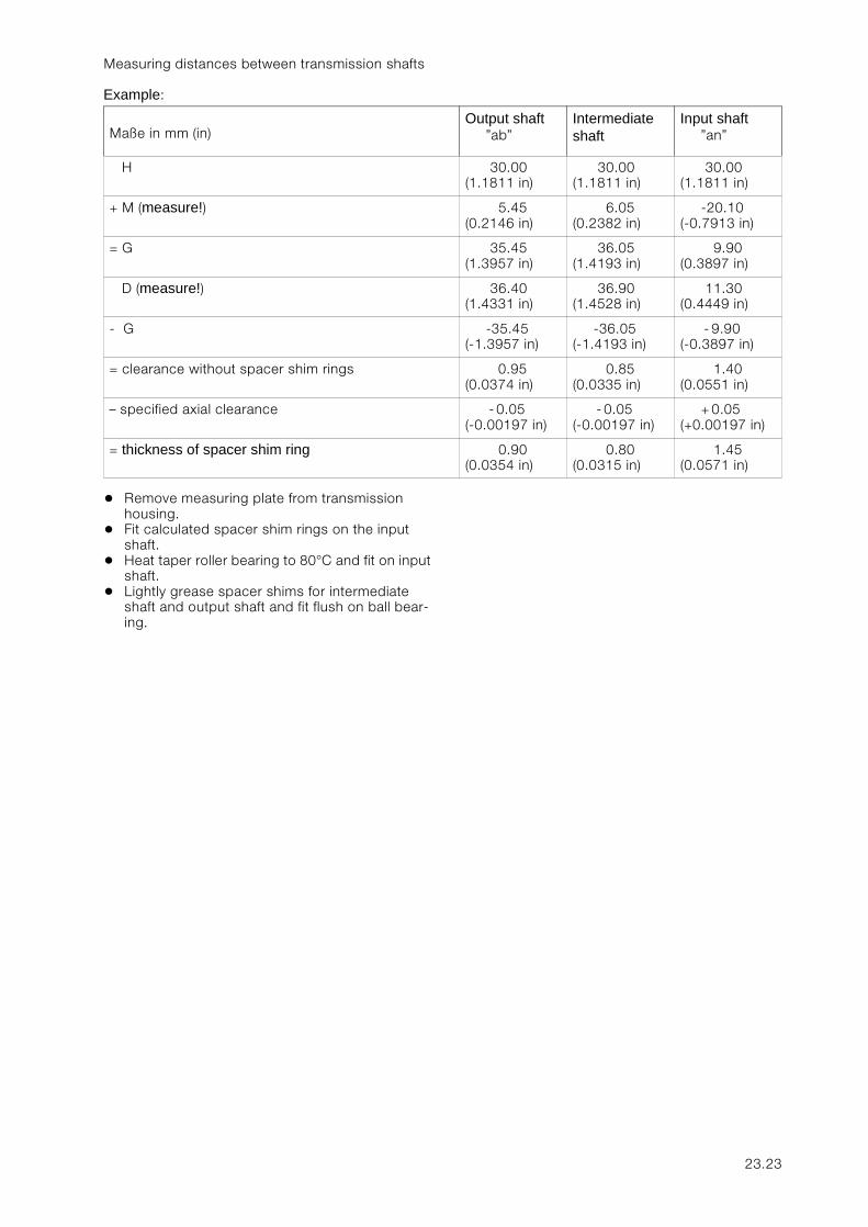
Measuring distances between transmission shafts
Example:
• Remove measuring plate from transmission housing.
• Fit calculated spacer shim rings on the input shaft.
• Heat taper roller bearing to 80°C and fit on input shaft.
• Lightly grease spacer shims for intermediate shaft and output shaft and fit flush on ball bear-ing.
Maße in mm (in)Output shaft
”ab”Intermediate shaft
Input shaft”an”
H 30.00 (1.1811 in)
30.00 (1.1811 in)
30.00 (1.1811 in)
+ M (measure!) 5.45 (0.2146 in)
6.05 (0.2382 in)
-20.10 (-0.7913 in)
= G 35.45 (1.3957 in)
36.05 (1.4193 in)
9.90(0.3897 in)
D (measure!) 36.40 (1.4331 in)
36.90 (1.4528 in)
11.30 (0.4449 in)
- G -35.45 (-1.3957 in)
-36.05 (-1.4193 in)
- 9.90 (-0.3897 in)
= clearance without spacer shim rings 0.95 (0.0374 in)
0.85 (0.0335 in)
1.40 (0.0551 in)
– specified axial clearance - 0.05 (-0.00197 in)
- 0.05 (-0.00197 in)
+ 0.05 (+0.00197 in)
= thickness of spacer shim ring 0.90 (0.0354 in)
0.80 (0.0315 in)
1.45 (0.0571 in)
23.23
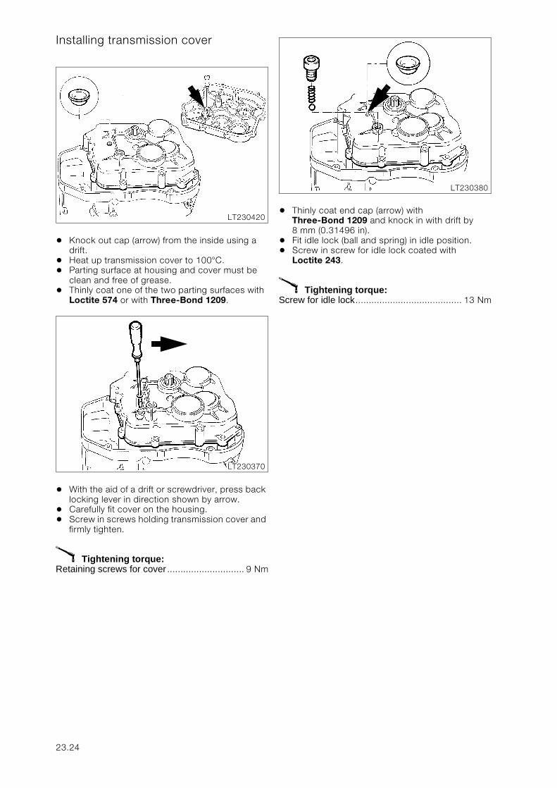
Installing transmission cover
• Knock out cap (arrow) from the inside using a drift.
• Heat up transmission cover to 100°C.• Parting surface at housing and cover must be
clean and free of grease.• Thinly coat one of the two parting surfaces with
Loctite 574 or with Three-Bond 1209.
• With the aid of a drift or screwdriver, press back locking lever in direction shown by arrow.
• Carefully fit cover on the housing.• Screw in screws holding transmission cover and
firmly tighten.
X Tightening torque:Retaining screws for cover ............................. 9 Nm
• Thinly coat end cap (arrow) with Three-Bond 1209 and knock in with drift by 8 mm (0.31496 in).
• Fit idle lock (ball and spring) in idle position.• Screw in screw for idle lock coated with
Loctite 243.
X Tightening torque:Screw for idle lock........................................ 13 Nm
LT230420
LT230370
LT230380
23.24
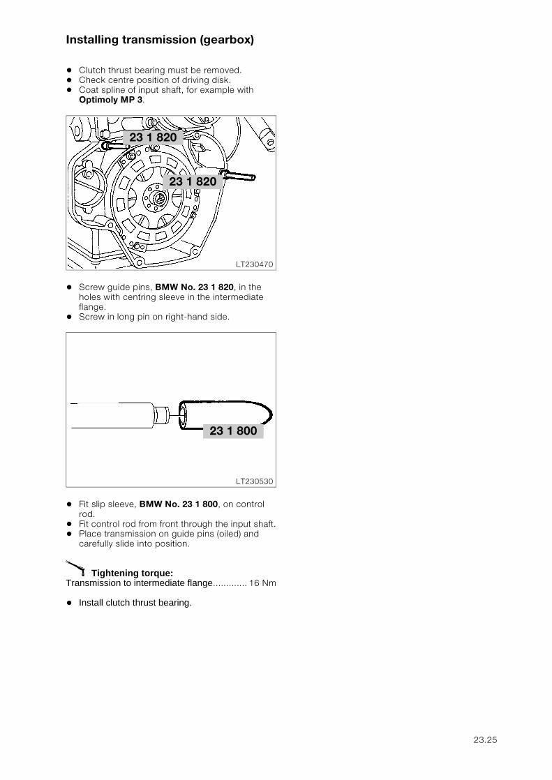
Installing transmission (gearbox)
• Clutch thrust bearing must be removed.• Check centre position of driving disk.• Coat spline of input shaft, for example with
Optimoly MP 3.
• Screw guide pins, BMW No. 23 1 820, in the holes with centring sleeve in the intermediate flange.
• Screw in long pin on right-hand side.
• Fit slip sleeve, BMW No. 23 1 800, on control rod.
• Fit control rod from front through the input shaft.• Place transmission on guide pins (oiled) and
carefully slide into position.
X Tightening torque:Transmission to intermediate flange............. 16 Nm
• Install clutch thrust bearing.
23 1 820
LT230470
23 1 820
LT230530
23 1 800
23.25
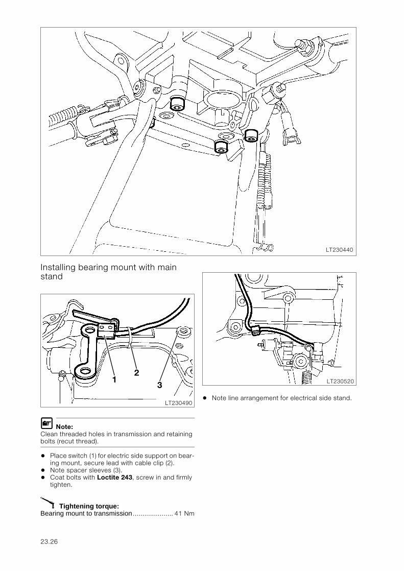
Installing bearing mount with main stand
L Note:Clean threaded holes in transmission and retaining bolts (recut thread).
• Place switch (1) for electric side support on bear-ing mount, secure lead with cable clip (2).
• Note spacer sleeves (3).• Coat bolts with Loctite 243, screw in and firmly
tighten.
X Tightening torque:Bearing mount to transmission ..................... 41 Nm
• Note line arrangement for electrical side stand.
LT230440
LT230490
12
3 LT230520
23.26
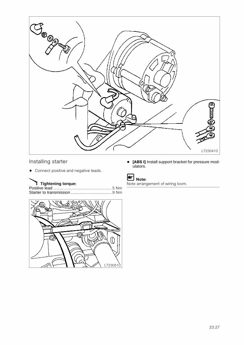
Installing starter
• Connect positive and negative leads.
X Tightening torque:Positive lead .................................................. 5 NmStarter to transmission ................................... 9 Nm
• [ABS I] Install support bracket for pressure mod-ulators.
L Note:Note arrangement of wiring loom.
LT230410
LT230510
23.27
Re-assembling motorcycle
• Install battery.• Intall Motronic control unit.• [ABS II] Install ABS unit.• Install battery.• Intall Motronic control unit.• [ABS I] Install control unit.• Install swinging arm.• Install footrest plates.• [ABS I] Install pressure modulators.• Install rear wheel drive.• Install suspension strut.• Install rear wheel.• Install brake caliper
L Note:Check ABS sensor gap.
• Install exhaust system.• Install rear mudguard.• Install side section of fairing.
X Tightening torques:Fixed swinging arm bearing at geabox ........... 8 NmFixed swinging arm bearing journal, free bearing................................................. 7.5 NmLocknut, free bearing ................................... 41 NmBearing pin of fixed bearing ....................... 150 Nm(clean thread + Loctite 2701)Bearing pin of loose bearing .......................... 7 Nm(clean thread + Loctite 2701 applied to entire length of thread on loose bearing pin)Locknut ...................................................... 105 NmSuspension strut to frame/rear wheel drive .. 51 NmRear wheel studs ....................................... 105 NmExhaust pipes to cylinder head .................... 21 NmExhaust system to holder/footrest plate ......... 9 NmFront silencer (muffler) to gearbox ................ 12 NmFootrest plate to gearbox ............................. 15 Nm
23.28
31
Inhalt Seite
31 Front fork
Technical Data ............................................................................................................................... 3
Removing telescopic fork ........................................................................................................5
Removing fork stabilisor ..............................................................................................................5
Removing telescopic fork without fork bridge ...................................................................5
Removing telescopic fork with fork bridge ..........................................................................5Removing upper fork bridge ................................................................................................................5
Removing and installing lower taper roller bearing ..........................................................6Removing taper roller bearing .............................................................................................................6Installing taper roller bearing ...............................................................................................................6
Removing and installing upper taper roller bearing .........................................................6Removing taper roller bearing .............................................................................................................6Installing taper roller bearing ...............................................................................................................6
Removing and installing bearing outer race in steering head .....................................7Removing bearing outer race ..............................................................................................................7Installing bearing outer race ................................................................................................................7
Measuring telescopic fork ...........................................................................................................8Checking lower fork bridge .................................................................................................................8Checking parallel alignment of fixed tubes ..........................................................................................9Checking runout of fixed tube ...........................................................................................................10
Disassembling telescopic fork ............................................................................................11
Removing fixed tube ....................................................................................................................11
Disassembling slider tube .........................................................................................................11
Disassembling fixed tube ..........................................................................................................12
Assembling telescopic fork ..................................................................................................14
Assembling fixed tube ................................................................................................................14
Assembling slider tube ...............................................................................................................16
Installing telescopic fork ........................................................................................................17
Adjusting steering bearing play ..............................................................................................18
Installing fork stabilisor ...............................................................................................................19
31.1

31.2
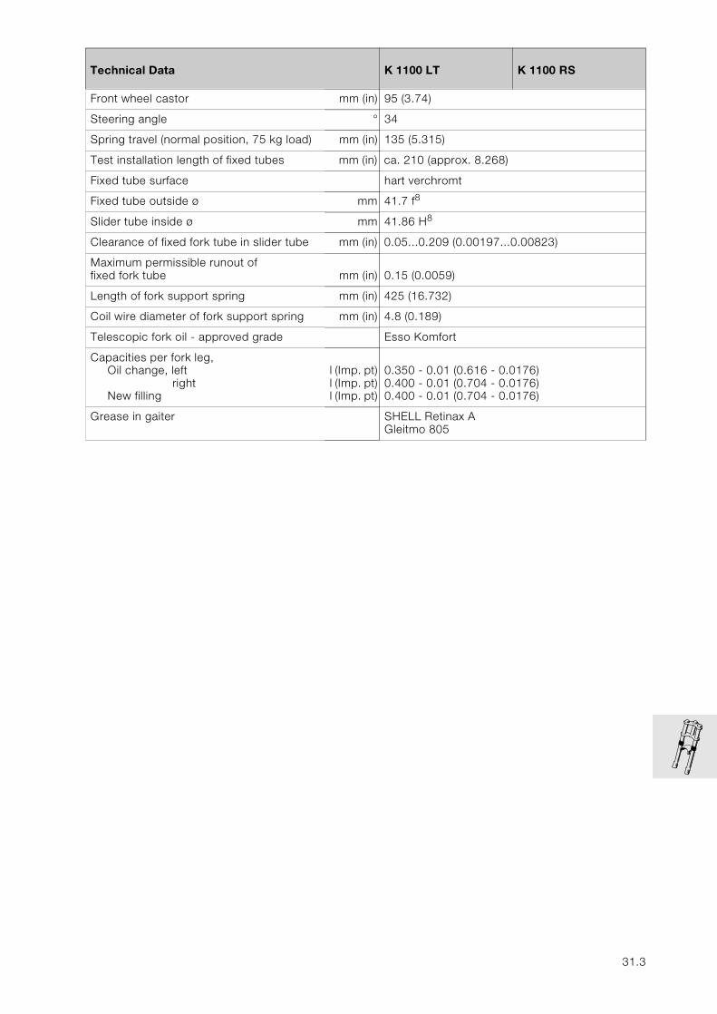
31
Technical Data K 1100 LT K 1100 RS
Front wheel castor mm (in) 95 (3.74)
Steering angle ° 34
Spring travel (normal position, 75 kg load) mm (in) 135 (5.315)
Test installation length of fixed tubes mm (in) ca. 210 (approx. 8.268)
Fixed tube surface hart verchromt
Fixed tube outside ø mm 41.7 f8
Slider tube inside ø mm 41.86 H8
Clearance of fixed fork tube in slider tube mm (in) 0.05...0.209 (0.00197...0.00823)
Maximum permissible runout of fixed fork tube mm (in) 0.15 (0.0059)
Length of fork support spring mm (in) 425 (16.732)
Coil wire diameter of fork support spring mm (in) 4.8 (0.189)
Telescopic fork oil - approved grade Esso Komfort
Capacities per fork leg,Oil change, left
rightNew filling
l (Imp. pt)l (Imp. pt)l (Imp. pt)
0.350 - 0.01 (0.616 - 0.0176)0.400 - 0.01 (0.704 - 0.0176)0.400 - 0.01 (0.704 - 0.0176)
Grease in gaiter SHELL Retinax AGleitmo 805
31.3

31.4
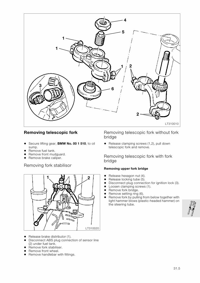
Removing telescopic fork
• Secure lifting gear, BMW No. 00 1 510, to oil sump.
• Remove fuel tank.• Remove front mudguard.• Remove brake caliper.
Removing fork stabilisor
• Release brake distributor (1).• Disconnect ABS plug connection of sensor line
(2) under fuel tank.• Remove fork stabiliser.• Remove front wheel.• Remove handlebar with fittings.
Removing telescopic fork without fork bridge
• Release clamping screws (1,2), pull down telescopic fork and remove.
Removing telescopic fork with fork bridge
Removing upper fork bridge
• Release hexagon nut (4).• Release locking tube (5).• Disconnect plug connection for ignition lock (3).• Loosen clamping screws (1).• Remove fork bridge.• Remove setting ring (6).• Remove fork by pulling from below together with
light hammer blows (plastic-headed hammer) on the steering tube.
LT310010
2
1
3
4
51
1
6
2
LT310020
21
31.5
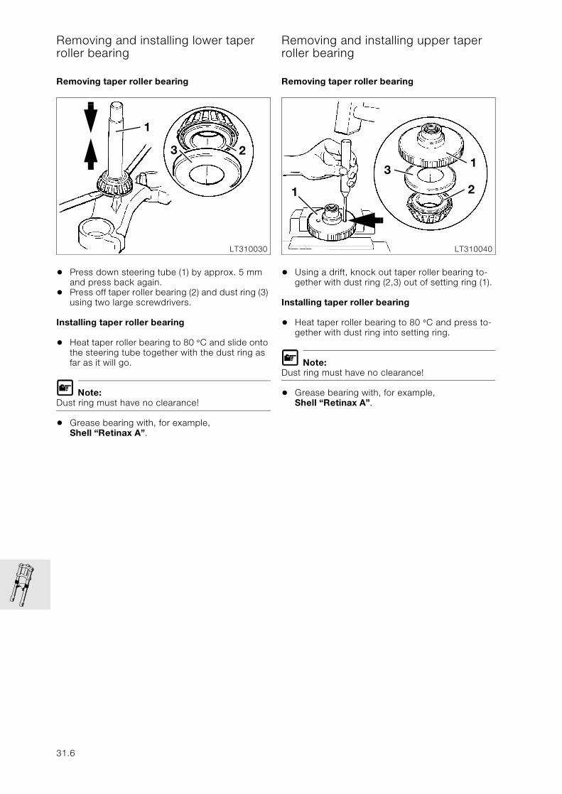
Removing and installing lower taper roller bearing
Removing taper roller bearing
• Press down steering tube (1) by approx. 5 mm and press back again.
• Press off taper roller bearing (2) and dust ring (3) using two large screwdrivers.
Installing taper roller bearing
• Heat taper roller bearing to 80 °C and slide onto the steering tube together with the dust ring as far as it will go.
L Note:Dust ring must have no clearance!
• Grease bearing with, for example, Shell “Retinax A”.
Removing and installing upper taper roller bearing
Removing taper roller bearing
• Using a drift, knock out taper roller bearing to-gether with dust ring (2,3) out of setting ring (1).
Installing taper roller bearing
• Heat taper roller bearing to 80 °C and press to-gether with dust ring into setting ring.
L Note:Dust ring must have no clearance!
• Grease bearing with, for example, Shell “Retinax A”.
LT310030
3
1
2
LT310040
1
1
3
2
31.6
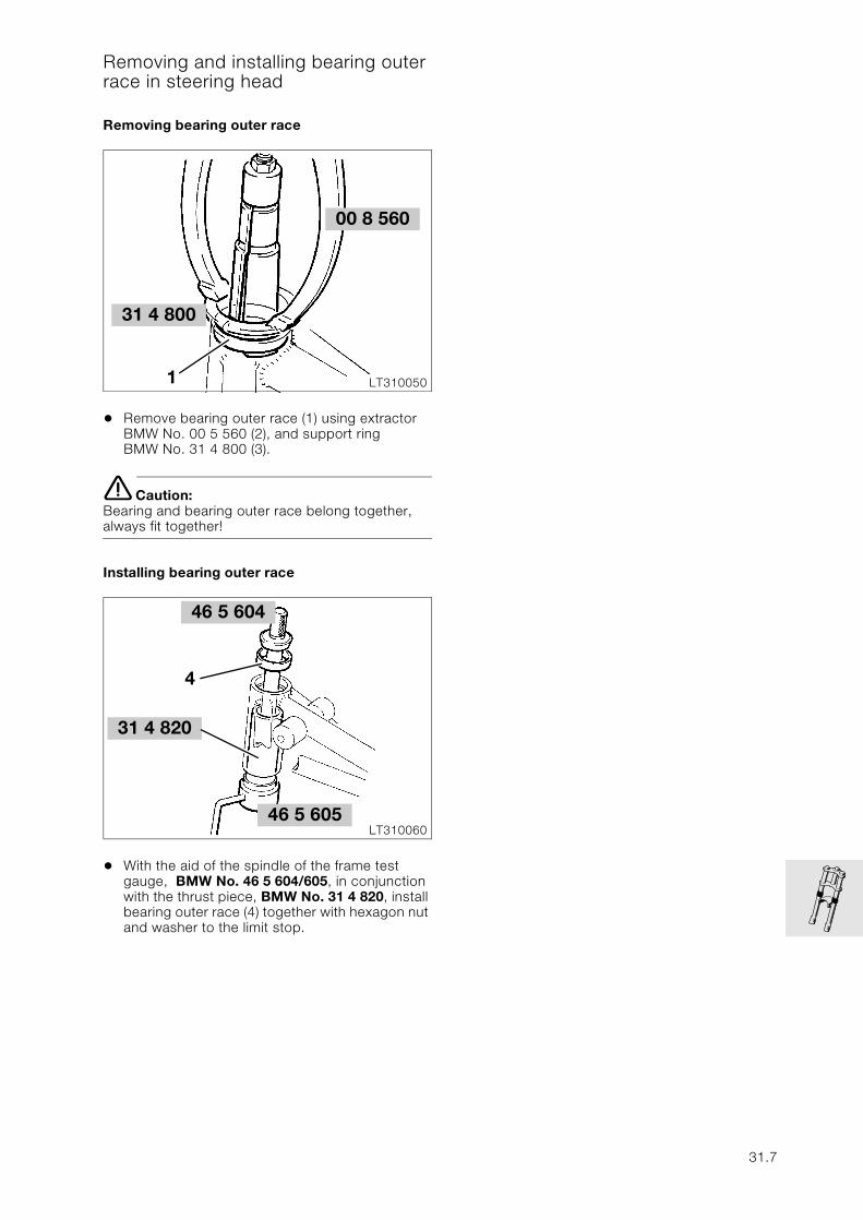
Removing and installing bearing outer race in steering head
Removing bearing outer race
• Remove bearing outer race (1) using extractor BMW No. 00 5 560 (2), and support ring BMW No. 31 4 800 (3).
e Caution:Bearing and bearing outer race belong together, always fit together!
Installing bearing outer race
• With the aid of the spindle of the frame test gauge, BMW No. 46 5 604/605, in conjunction with the thrust piece, BMW No. 31 4 820, install bearing outer race (4) together with hexagon nut and washer to the limit stop.
31 4 800
LT310050
00 8 560
1
46 5 604
LT31006046 5 605
4
31 4 820
31.7
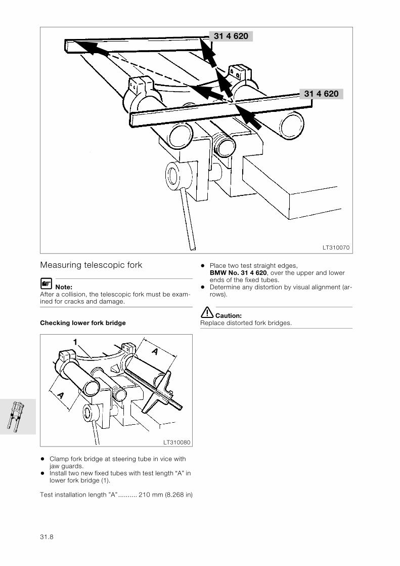
Measuring telescopic fork
L Note:After a collision, the telescopic fork must be exam-ined for cracks and damage.
Checking lower fork bridge
• Clamp fork bridge at steering tube in vice with jaw guards.
• Install two new fixed tubes with test length “A” in lower fork bridge (1).
Test installation length ”A”.......... 210 mm (8.268 in)
• Place two test straight edges, BMW No. 31 4 620, over the upper and lower ends of the fixed tubes.
• Determine any distortion by visual alignment (ar-rows).
e Caution:Replace distorted fork bridges.
31 4 620
LT310070
31 4 620
LT310080
A1
A
31.8
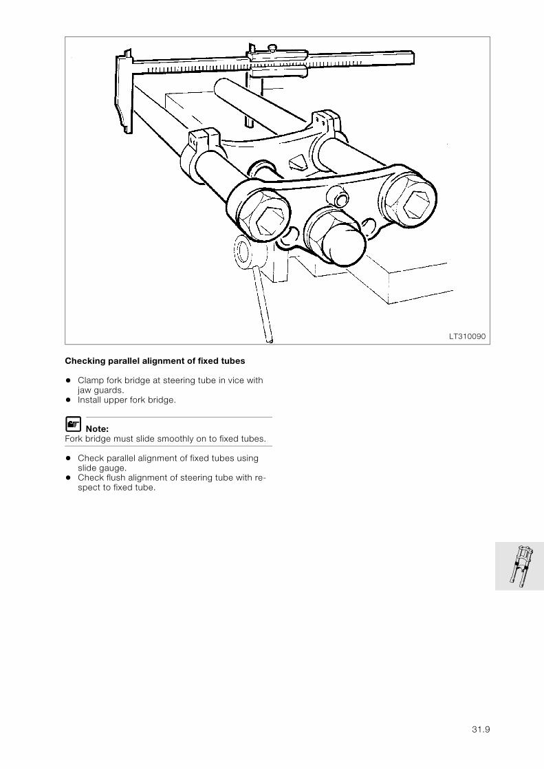
Checking parallel alignment of fixed tubes
• Clamp fork bridge at steering tube in vice with jaw guards.
• Install upper fork bridge.
L Note:Fork bridge must slide smoothly on to fixed tubes.
• Check parallel alignment of fixed tubes using slide gauge.
• Check flush alignment of steering tube with re-spect to fixed tube.
LT310090
31.9
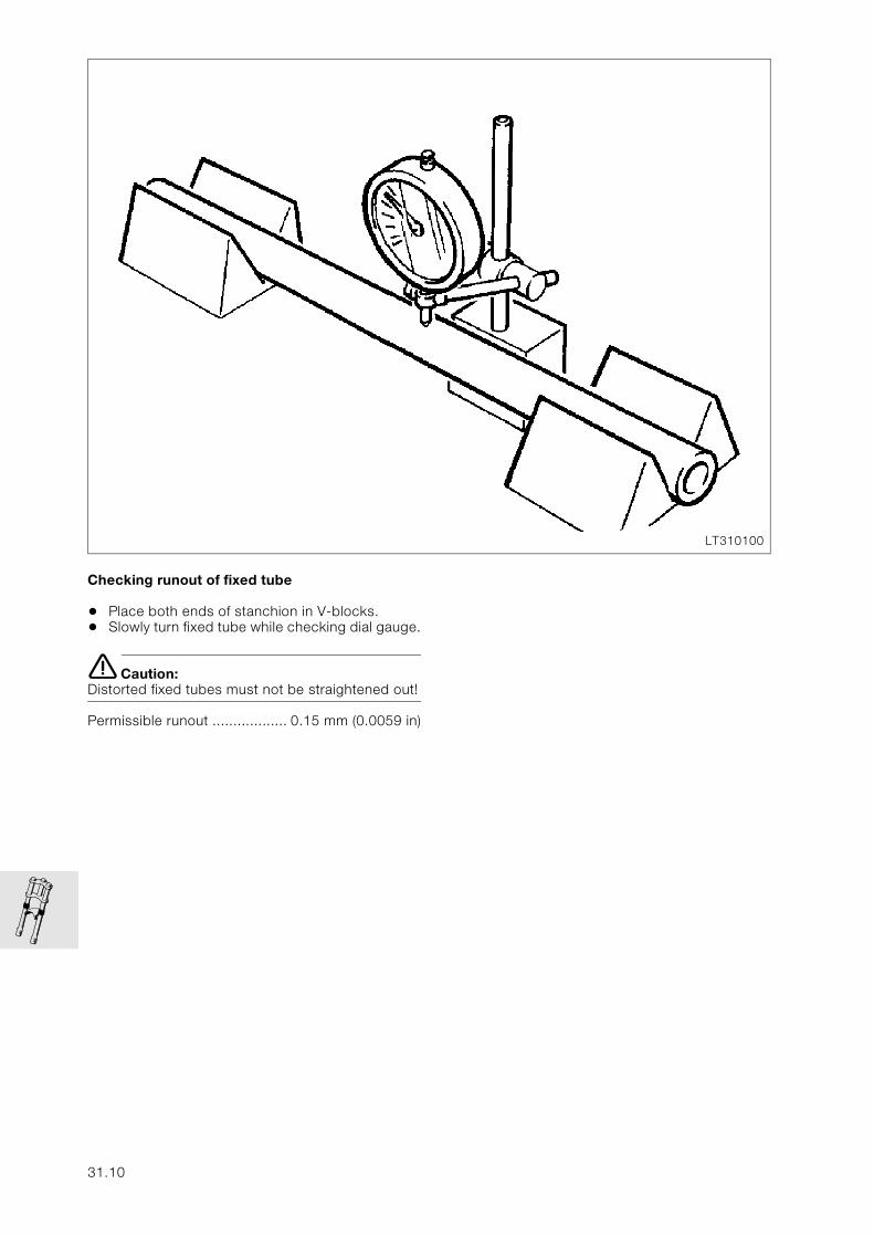
Checking runout of fixed tube
• Place both ends of stanchion in V-blocks.• Slowly turn fixed tube while checking dial gauge.
e Caution:Distorted fixed tubes must not be straightened out!
Permissible runout .................. 0.15 mm (0.0059 in)
LT310100
31.10
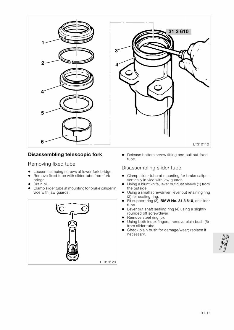
Disassembling telescopic fork
Removing fixed tube
• Loosen clamping screws at lower fork bridge.• Remove fixed tube with slider tube from fork
bridge.• Drain oil.• Clamp slider tube at mounting for brake caliper in
vice with jaw guards.
• Release bottom screw fitting and pull out fixed tube.
Disassembling slider tube
• Clamp slider tube at mounting for brake caliper vertically in vice with jaw guards.
• Using a blunt knife, lever out dust sleeve (1) from the outside.
• Using a small screwdriver, lever out retaining ring (2) for sealing ring.
• Fit support ring (3), BMW No. 31 3 610, on slider tube.
• Lever out shaft sealing ring (4) using a slightly rounded off screwdriver.
• Remove steel ring (5).• Using both index fingers, remove plain bush (6)
from slider tube.• Check plain bush for damage/wear; replace if
necessary.
31 3 610
LT310110
1
42
5
6
4
3
LT310120
31.11
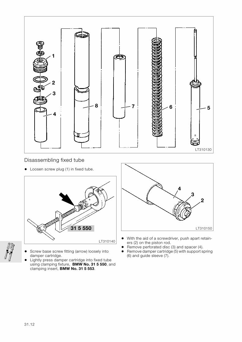
Disassembling fixed tube
• Loosen screw plug (1) in fixed tube.
• Screw base screw fitting (arrow) loosely into damper cartridge.
• Lightly press damper cartridge into fixed tube using clamping fixture, BMW No. 31 5 550, and clamping insert, BMW No. 31 5 553.
• With the aid of a screwdriver, push apart retain-ers (2) on the piston rod.
• Remove perforated disc (3) and spacer (4).• Remove damper cartridge (5) with support spring
(6) and guide sleeve (7).
LT310130
5678
4
3
2
1
31 5 550
LT310140
LT310150
43
2
31.12
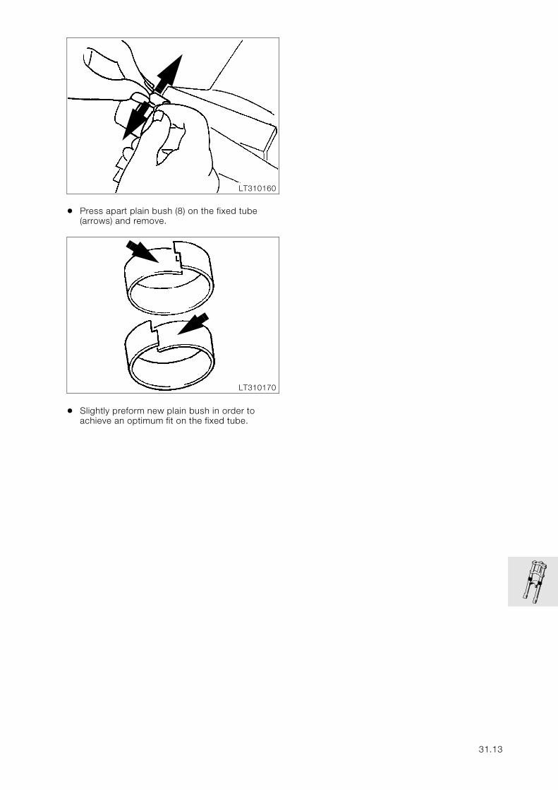
• Press apart plain bush (8) on the fixed tube (arrows) and remove.
• Slightly preform new plain bush in order to achieve an optimum fit on the fixed tube.
LT310160
LT310170
31.13
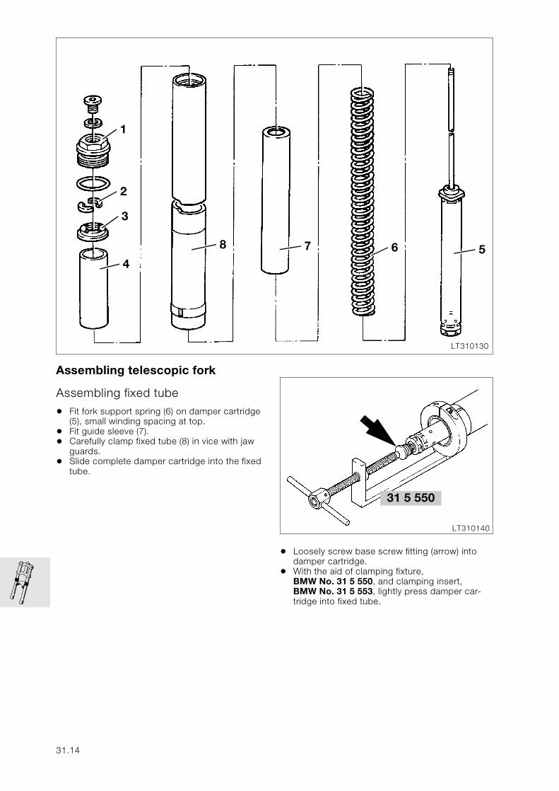
Assembling telescopic fork
Assembling fixed tube
• Fit fork support spring (6) on damper cartridge (5), small winding spacing at top.
• Fit guide sleeve (7).• Carefully clamp fixed tube (8) in vice with jaw
guards.• Slide complete damper cartridge into the fixed
tube.
• Loosely screw base screw fitting (arrow) into damper cartridge.
• With the aid of clamping fixture, BMW No. 31 5 550, and clamping insert, BMW No. 31 5 553, lightly press damper car-tridge into fixed tube.
LT310130
5678
4
3
2
1
31 5 550
LT310140
31.14
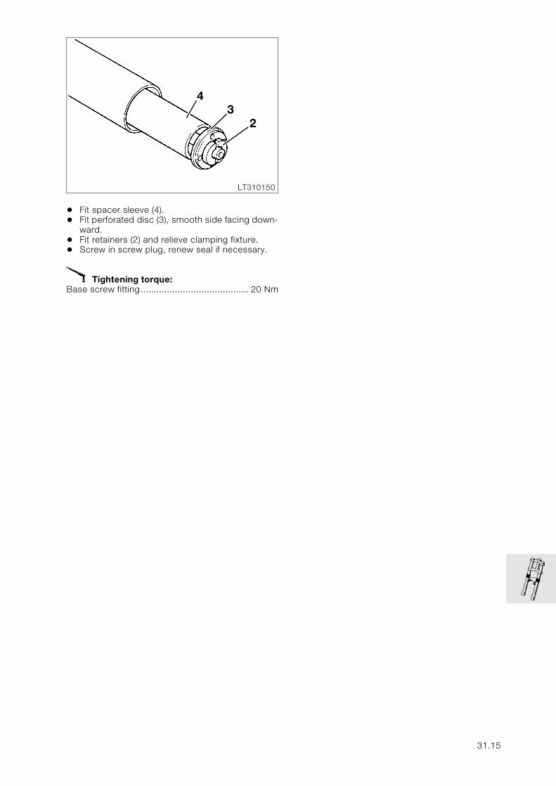
• Fit spacer sleeve (4).• Fit perforated disc (3), smooth side facing down-
ward.• Fit retainers (2) and relieve clamping fixture.• Screw in screw plug, renew seal if necessary.
X Tightening torque:Base screw fitting......................................... 20 Nm
LT310150
43
2
31.15
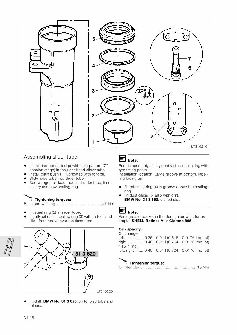
Assembling slider tube
• Install damper cartridge with hole pattern “Z” (tension stage) in the right-hand slider tube.
• Install plain bush (1) lubricated with fork oil.• Slide fixed tube into slider tube.• Screw together fixed tube and slider tube, if nec-
essary use new sealing ring.
X Tightening torques:Base screw fitting......................................... 47 Nm
• Fit steel ring (2) in slider tube.• Lightly oil radial sealing ring (3) with fork oil and
slide from above over the fixed tube.
• Fit drift, BMW No. 31 3 620, on to fixed tube and release.
L Note:Prior to assembly, lightly coat radial sealing ring with tyre fitting paste.Installation location: Large groove at bottom, label-ling facing up.
• Fit retaining ring (4) in groove above the sealing ring.
• Fit dust gaiter (5) also with drift, BMW No. 31 3 650, dished side.
L Note:Pack grease pocket in the dust gaiter with, for ex-ample, SHELL Retinax A or Gleitmo 805.
Oil capacity:Oil change:left..................0,35 - 0,01 l (0.616 - 0.0176 Imp. pt)right ...............0,40 - 0,01 l (0.704 - 0.0176 Imp. pt)New filling:left, right.........0,40 - 0,01 l (0.704 - 0.0176 Imp. pt)
X Tightening torque:Oil filler plug ................................................. 10 Nm
LT310210
5
Z
4
3
2
1
TOP
7
6
31 3 620
LT310220
31.16
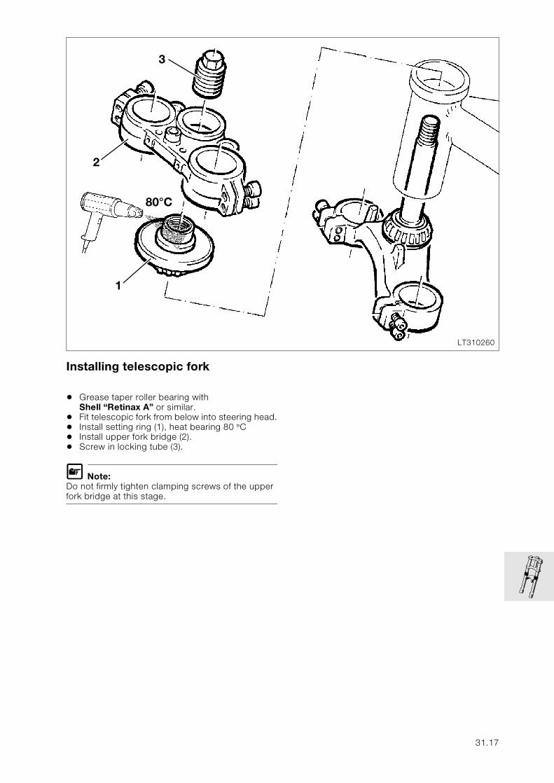
Installing telescopic fork
• Grease taper roller bearing with Shell “Retinax A” or similar.
• Fit telescopic fork from below into steering head.• Install setting ring (1), heat bearing 80 °C • Install upper fork bridge (2).• Screw in locking tube (3).
L Note:Do not firmly tighten clamping screws of the upper fork bridge at this stage.
LT310260
3
2
1
80°C
31.17
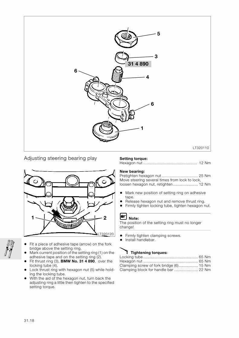
Adjusting steering bearing play
• Fit a piece of adhesive tape (arrow) on the fork bridge above the setting ring.
• Mark current position of the setting ring (1) on the adhesive tape and on the setting ring (2).
• Fit thrust ring (3), BMW No. 31 4 890, over the locking tube (4).
• Lock thrust ring with hexagon nut (5) while hold-ing the locking tube.
• With the aid of the hexagon nut, turn back the adjusting ring a little then tighten to the specified setting torque.
Setting torque: Hexagon nut ............................................... 12 Nm
New bearing: Pretighten hexagon nut ................................ 25 NmMove steering several times from lock to lock, loosen hexagon nut, retighten...................... 12 Nm
• Mark new position of setting ring on adhesive tape.
• Release hexagon nut and remove thrust ring.• Firmly tighten locking tube, tighten hexagon nut.
L Note:The position of the setting ring must no longer change!
• Firmly tighten clamping screws.• Install handlebar.
X Tightening torques:Locking tube ................................................ 65 NmHexagon nut ................................................ 65 NmClamping screw of fork bridge (6)................. 15 NmClamping block for handle bar ..................... 22 Nm
31 4 890
LT320110
6
5
4
6
1
3
LT320120
1 2
31.18
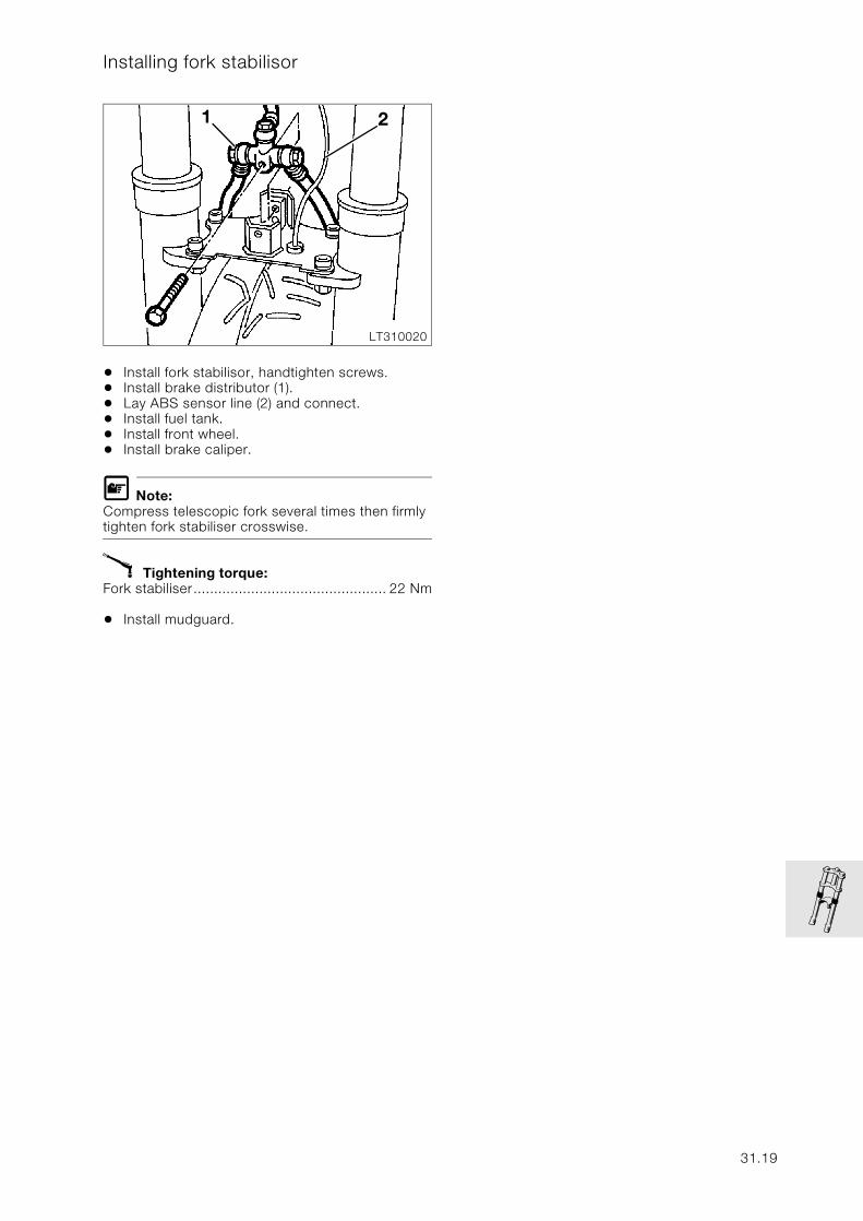
Installing fork stabilisor
• Install fork stabilisor, handtighten screws.• Install brake distributor (1).• Lay ABS sensor line (2) and connect. • Install fuel tank.• Install front wheel.• Install brake caliper.
L Note:Compress telescopic fork several times then firmly tighten fork stabiliser crosswise.
X Tightening torque:Fork stabiliser............................................... 22 Nm
• Install mudguard.
LT310020
21
31.19

31.20
32
Contents Page
32 Steering
Technical Data ............................................................................................................................... 3
Removing and installing left and right handlebar fittings ......................................5
Removing and installing left handlebar fitting .....................................................................5Removing and installing handlebar weight ...........................................................................................5
Removing and installing right handlebar fitting ..................................................................7
Removing and installing handlebar ....................................................................................8
Removing and installing handlebar clamping blocks ......................................................9
Removing and installing accelerator cable .................................................................10
Removing and installing clutch cable .............................................................................11
Removing and installing operating cable for increasing starting speed .....12
Adjusting steering bearing play ..........................................................................................13
32.1

32.2
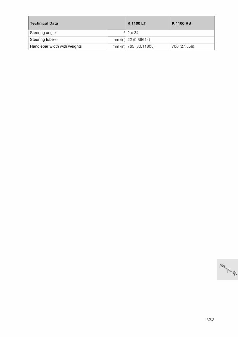
32
Technical Data K 1100 LT K 1100 RS
Steering anglel ° 2 x 34
Steering tube-ø mm (in) 22 (0.86614)
Handlebar width with weights mm (in) 765 (30.11805) 700 (27.559)
32.3

32.4
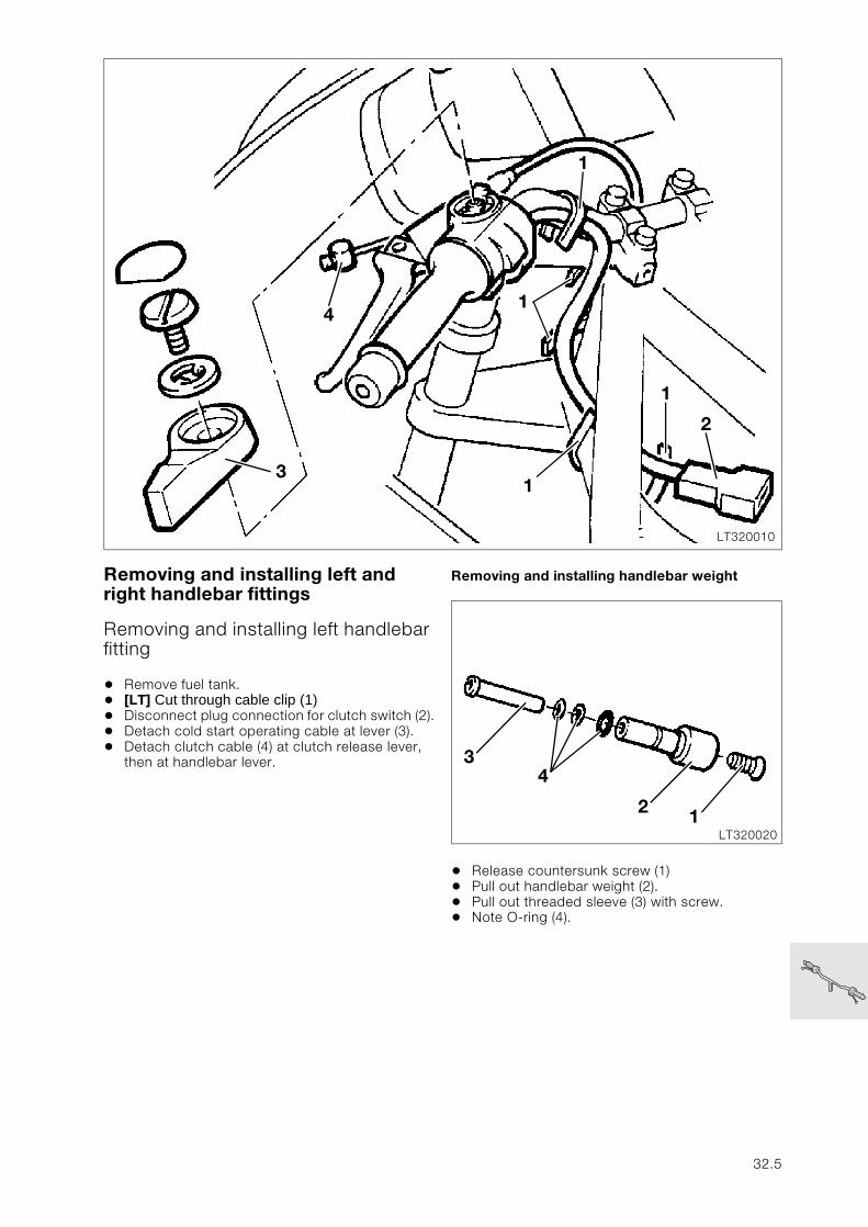
Removing and installing left and right handlebar fittings
Removing and installing left handlebar fitting
• Remove fuel tank.• [LT] Cut through cable clip (1)• Disconnect plug connection for clutch switch (2).• Detach cold start operating cable at lever (3).• Detach clutch cable (4) at clutch release lever,
then at handlebar lever.
Removing and installing handlebar weight
• Release countersunk screw (1)• Pull out handlebar weight (2).• Pull out threaded sleeve (3) with screw.• Note O-ring (4).
LT320010
3
4
2
1
1
1
1
LT32002012
34
32.5
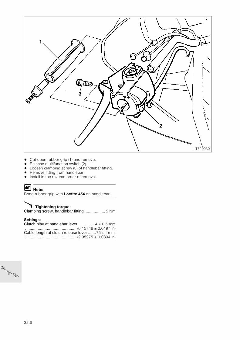
• Cut open rubber grip (1) and remove.• Release multifunction switch (2).• Loosen clamping screw (3) of handlebar fitting.• Remove fitting from handlebar.• Install in the reverse order of removal.
L Note:Bond rubber grip with Loctite 454 on handlebar.
X Tightening torque:Clamping screw, handlebar fitting .................. 5 Nm
Settings:Clutch play at handlebar lever...............4 ± 0.5 mm............................................. (0.15748 ± 0.0197 in)Cable length at clutch release lever .......75 ± 1 mm ............................................. (2.95275 ± 0.0394 in)
LT320030
1
3
2
32.6
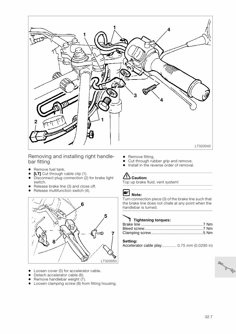
Removing and installing right handle-bar fitting
• Remove fuel tank.• [LT] Cut through cable clip (1).• Disconnect plug connection (2) for brake light
switch.• Release brake line (3) and close off.• Release multifunction switch (4).
• Loosen cover (5) for accelerator cable.• Detach accelerator cable (6).• Remove handlebar weight (7).• Loosen clamping screw (8) from fitting housing.
• Remove fitting.• Cut through rubber grip and remove.• Install in the reverse order of removal.
e Caution:Top up brake fluid, vent system!
L Note:Turn connection piece (3) of the brake line such that the brake line does not chafe at any point when the handlebar is turned.
X Tightening torques:Brake line ........................................................7 NmBleed screw.....................................................7 NmClamping screw...............................................5 Nm
Setting:Accelerator cable play............. 0.75 mm (0.0295 in)
LT320040
3
1
1
4
4
2
1
LT320050
8
7
6
5
32.7
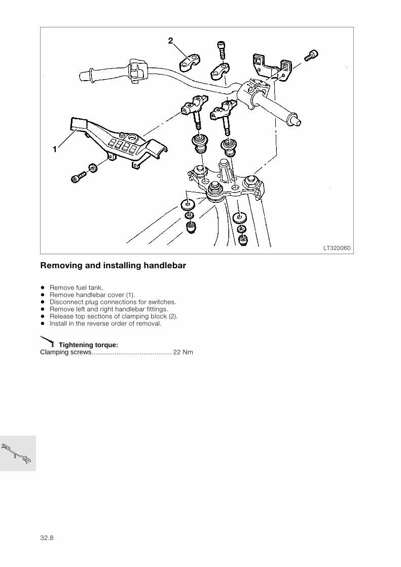
Removing and installing handlebar
• Remove fuel tank.• Remove handlebar cover (1).• Disconnect plug connections for switches.• Remove left and right handlebar fittings.• Release top sections of clamping block (2).• Install in the reverse order of removal.
X Tightening torque:Clamping screws.......................................... 22 Nm
LT320060
1
2
32.8
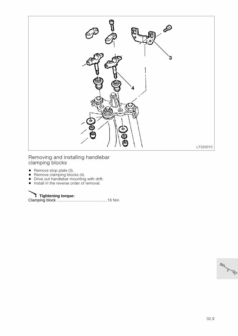
Removing and installing handlebar clamping blocks
• Remove stop plate (3).• Remove clamping blocks (4).• Drive out handlebar mounting with drift.• Install in the reverse order of removal.
X Tightening torque:Clamping block ............................................ 16 Nm
LT320070
4
3
32.9
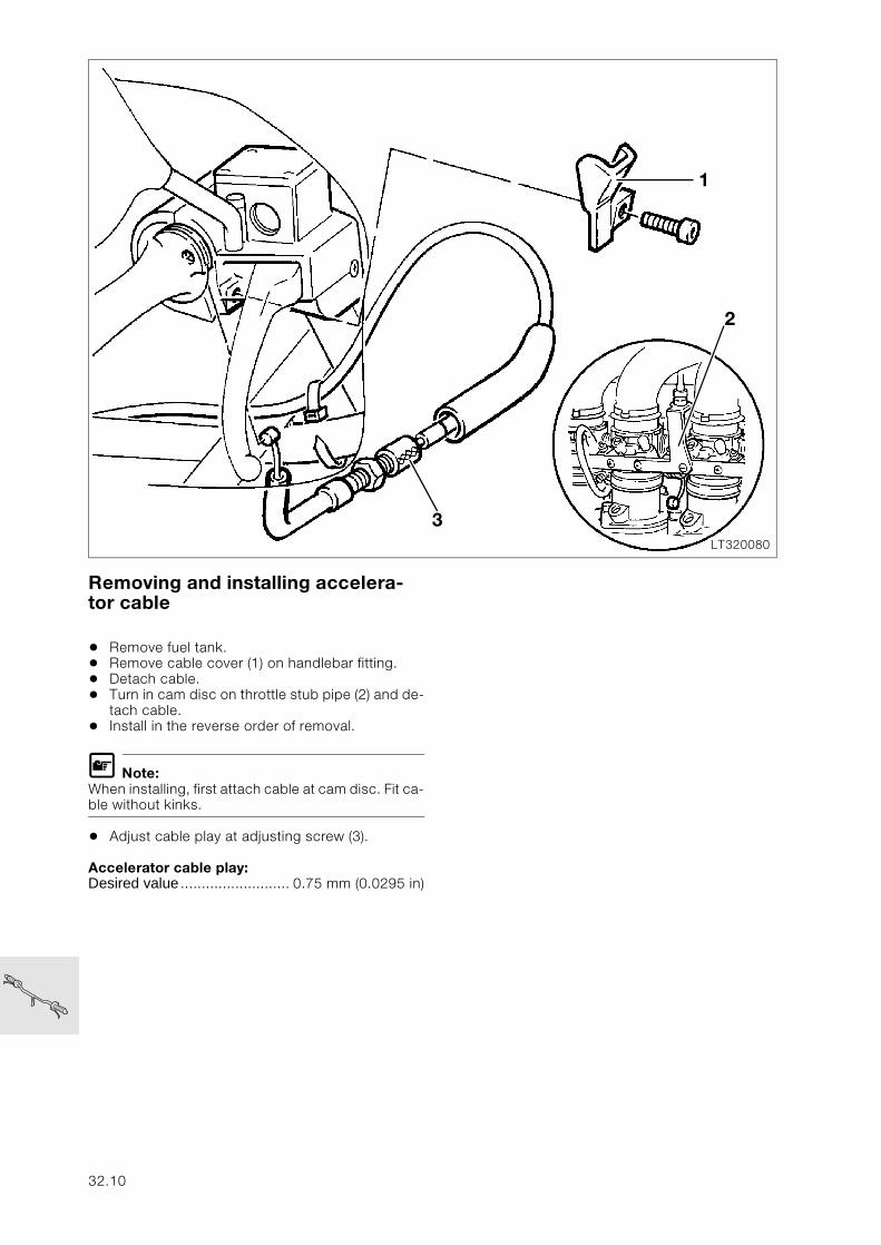
Removing and installing accelera-tor cable
• Remove fuel tank.• Remove cable cover (1) on handlebar fitting.• Detach cable.• Turn in cam disc on throttle stub pipe (2) and de-
tach cable.• Install in the reverse order of removal.
L Note:When installing, first attach cable at cam disc. Fit ca-ble without kinks.
• Adjust cable play at adjusting screw (3).
Accelerator cable play:Desired value .......................... 0.75 mm (0.0295 in)
LT320080
1
3
2
32.10
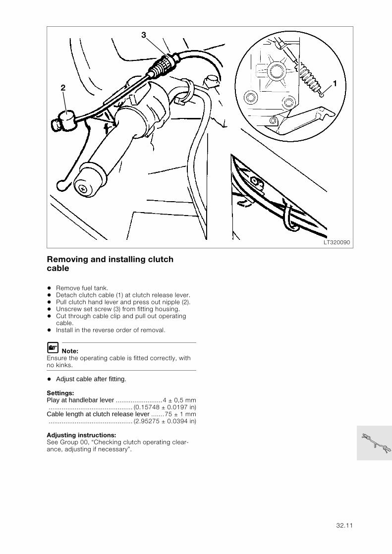
Removing and installing clutch cable
• Remove fuel tank.• Detach clutch cable (1) at clutch release lever.• Pull clutch hand lever and press out nipple (2).• Unscrew set screw (3) from fitting housing.• Cut through cable clip and pull out operating
cable.• Install in the reverse order of removal.
L Note:Ensure the operating cable is fitted correctly, with no kinks.
• Adjust cable after fitting.
Settings:Play at handlebar lever .........................4 ± 0,5 mm............................................. (0.15748 ± 0.0197 in)Cable length at clutch release lever .......75 ± 1 mm............................................. (2.95275 ± 0.0394 in)
Adjusting instructions:See Group 00, “Checking clutch operating clear-ance, adjusting if necessary”.
LT320090
12
3
32.11
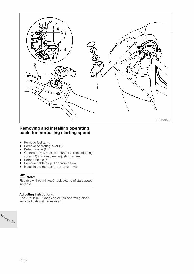
Removing and installing operating cable for increasing starting speed
• Remove fuel tank.• Remove operating lever (1).• Detach cable (2).• On throttle rail, release locknut (3) from adjusting
screw (4) and unscrew adjusting screw.• Detach nipple (5).• Remove cable by pulling from below.• Install in the reverse order of removal.
L Note:Fit cable without kinks. Check setting of start speed increase.
Adjusting instructions:See Group 00, “Checking clutch operating clear-ance, adjusting if necessary”.
LT320100
4
2
3
5
1
32.12
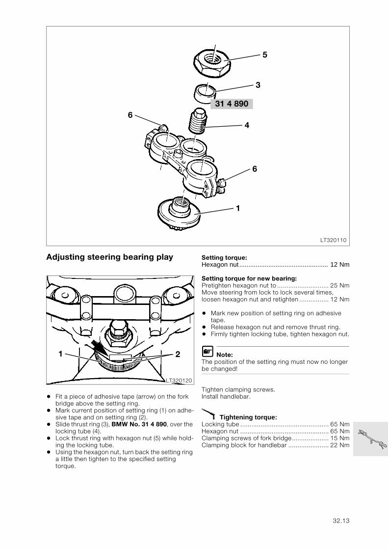
Adjusting steering bearing play
• Fit a piece of adhesive tape (arrow) on the fork bridge above the setting ring.
• Mark current position of setting ring (1) on adhe-sive tape and on setting ring (2).
• Slide thrust ring (3), BMW No. 31 4 890, over the locking tube (4).
• Lock thrust ring with hexagon nut (5) while hold-ing the locking tube.
• Using the hexagon nut, turn back the setting ring a little then tighten to the specified setting torque.
Setting torque:Hexagon nut ................................................. 12 Nm
Setting torque for new bearing:Pretighten hexagon nut to ............................ 25 NmMove steering from lock to lock several times, loosen hexagon nut and retighten ................ 12 Nm
• Mark new position of setting ring on adhesive tape.
• Release hexagon nut and remove thrust ring.• Firmly tighten locking tube, tighten hexagon nut.
L Note:The position of the setting ring must now no longer be changed!
Tighten clamping screws.Install handlebar.
X Tightening torque:Locking tube ................................................ 65 NmHexagon nut ................................................ 65 NmClamping screws of fork bridge.................... 15 NmClamping block for handlebar ...................... 22 Nm
31 4 890
LT320110
6
5
4
6
1
3
LT320120
1 2
32.13

32.14
33
Contents Page
33 Rear wheel drive
Technical data ................................................................................................................................ 3
Removing, disassembling, assembling and installing rear wheel drive ........5
Removing rear wheel drive .........................................................................................................5
Removing, disassembling and assembling drive bevel gear .......................................5Removing retaining ring .......................................................................................................................5Disassembling drive bevel gear ...........................................................................................................7Removing needle bearing for drive bevel gear .....................................................................................8Installing needle bearing for drive bevel gear .......................................................................................8Assembling drive bevel gear ................................................................................................................9
Installing drive bevel gear ..........................................................................................................10
Removing and installing taper needle bearing in rear wheel drive .........................11
Removing crown wheel ..............................................................................................................12
Installing crown wheel .................................................................................................................13
Checking/adjusting tooth backlash ......................................................................................14
Checking contact pattern ..........................................................................................................15
Shimming housing cover ...........................................................................................................16
Installing housing cover .............................................................................................................16
Installing slider ................................................................................................................................16
Installing rear wheel drive ..........................................................................................................17
Removing, disassembling and assembling rear swinging arm .........................19
Removing and installing taper roller bearing ....................................................................19
Removing and installing gaiter ................................................................................................20
Removing drive shaft ...................................................................................................................20Checking universal joint for wear .......................................................................................................20Removing retaining ring .....................................................................................................................20
Installing drive shaft .....................................................................................................................20
Installing swinging arm ...............................................................................................................21Installing footrest plates ....................................................................................................................21
33.1

33.2
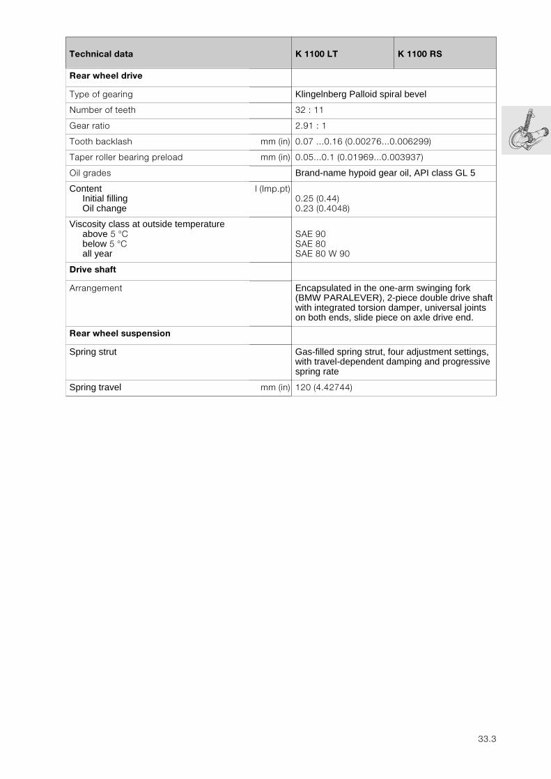
33
Technical data K 1100 LT K 1100 RS
Rear wheel drive
Type of gearing Klingelnberg Palloid spiral bevel
Number of teeth 32 : 11
Gear ratio 2.91 : 1
Tooth backlash mm (in) 0.07 ...0.16 (0.00276...0.006299)
Taper roller bearing preload mm (in) 0.05...0.1 (0.01969...0.003937)
Oil grades Brand-name hypoid gear oil, API class GL 5
ContentInitial fillingOil change
l (Imp.pt)0.25 (0.44)0.23 (0.4048)
Viscosity class at outside temperatureabove 5 °Cbelow 5 °Call year
SAE 90SAE 80SAE 80 W 90
Drive shaft
Arrangement Encapsulated in the one-arm swinging fork (BMW PARALEVER), 2-piece double drive shaft with integrated torsion damper, universal joints on both ends, slide piece on axle drive end.
Rear wheel suspension
Spring strut Gas-filled spring strut, four adjustment settings, with travel-dependent damping and progressive spring rate
Spring travel mm (in) 120 (4.42744)
33.3

33.4
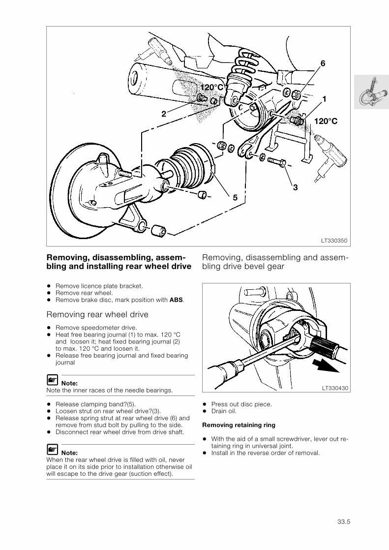
Removing, disassembling, assem-bling and installing rear wheel drive
• Remove licence plate bracket.• Remove rear wheel.• Remove brake disc, mark position with ABS.
Removing rear wheel drive
• Remove speedometer drive.• Heat free bearing journal (1) to max. 120 °C
and loosen it; heat fixed bearing journal (2) to max. 120 °C and loosen it.
• Release free bearing journal and fixed bearing journal
L Note:Note the inner races of the needle bearings.
• Release clamping band?(5).• Loosen strut on rear wheel drive?(3).• Release spring strut at rear wheel drive (6) and
remove from stud bolt by pulling to the side.• Disconnect rear wheel drive from drive shaft.
L Note:When the rear wheel drive is filled with oil, never place it on its side prior to installation otherwise oil will escape to the drive gear (suction effect).
Removing, disassembling and assem-bling drive bevel gear
• Press out disc piece.• Drain oil.
Removing retaining ring
• With the aid of a small screwdriver, lever out re-taining ring in universal joint.
• Install in the reverse order of removal.
LT330350
2
120°C
6
120°C
1
53
LT330430
33.5
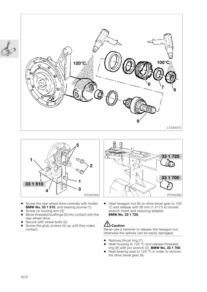
• Screw the rear wheel drive centrally with holder, BMW No. 33 1 510, and bearing journal (1).
• Screw on locking arm (3).• Move threaded bushings (5) into contact with the
rear wheel drive.• Secure with wheel bolts (2).• Screw the grub screws (4) up until they make
contact.
• Heat hexagon nut (6) on drive bevel gear to 100 °C and release with 36 mm (1.4173 in) socket wrench insert and reducing adapter, BMW No. 33 1 720.
e Caution:Never use a hammer to release the hexagon nut, otherwise the splines can be easily damaged.
• Remove thrust ring (7).• Heat housing to 120 °C and release threaded
ring (8) with pin wrench (2), BMW No. 33 1 700.• Heat bearing seat to 120 °C in order to remove
the drive bevel gear (9).
LT330010
9
87
6
120°C 100°C
33 1 510
RT330350
1
4
2
5
1
3
33 1 720
RT330360
33 1 700
33.6
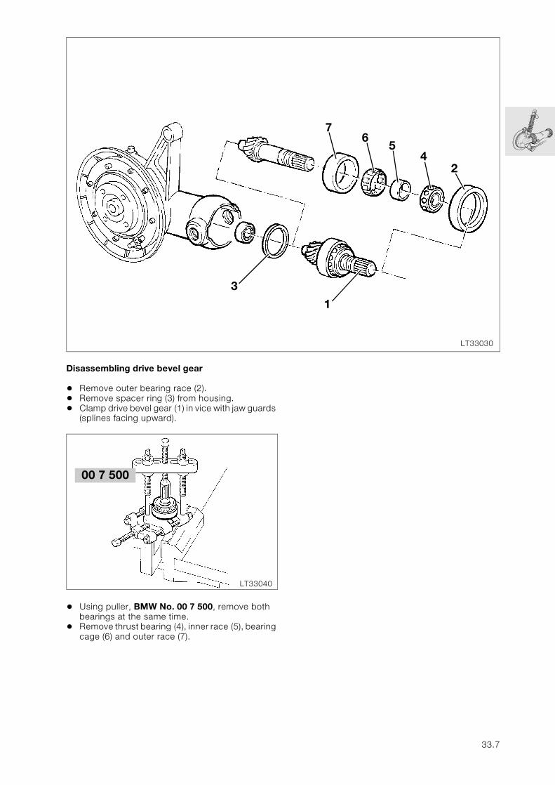
Disassembling drive bevel gear
• Remove outer bearing race (2).• Remove spacer ring (3) from housing.• Clamp drive bevel gear (1) in vice with jaw guards
(splines facing upward).
• Using puller, BMW No. 00 7 500, remove both bearings at the same time.
• Remove thrust bearing (4), inner race (5), bearing cage (6) and outer race (7).
LT33030
3
1
76
54
2
00 7 500
LT33040
33.7
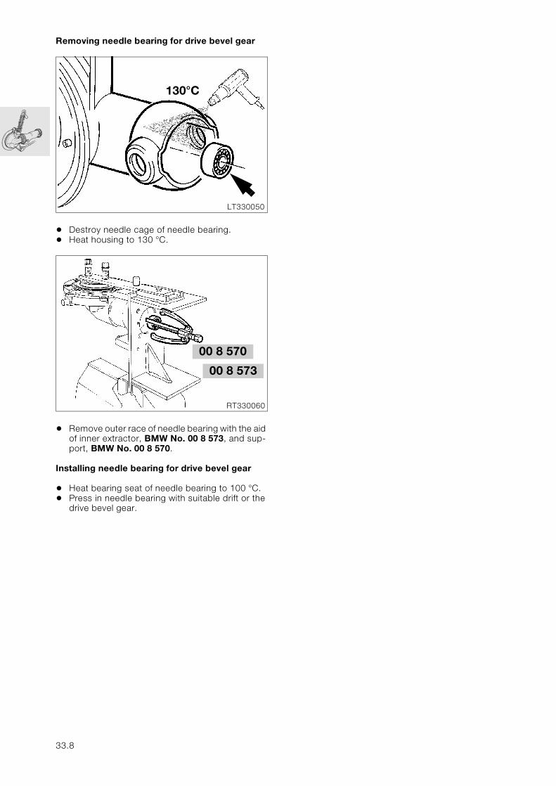
Removing needle bearing for drive bevel gear
• Destroy needle cage of needle bearing.• Heat housing to 130 °C.
• Remove outer race of needle bearing with the aid of inner extractor, BMW No. 00 8 573, and sup-port, BMW No. 00 8 570.
Installing needle bearing for drive bevel gear
• Heat bearing seat of needle bearing to 100 °C. • Press in needle bearing with suitable drift or the
drive bevel gear.
LT330050
130°C
00 8 570
RT330060
00 8 573
33.8
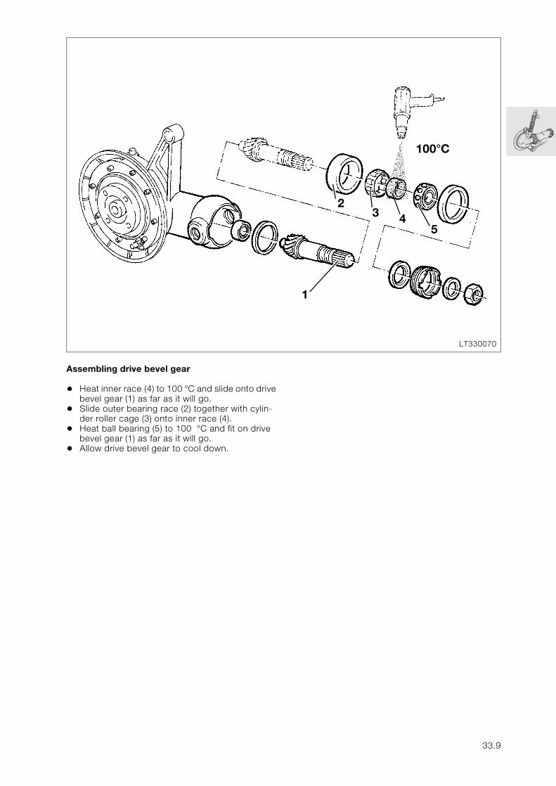
Assembling drive bevel gear
• Heat inner race (4) to 100 °C and slide onto drive bevel gear (1) as far as it will go.
• Slide outer bearing race (2) together with cylin-der roller cage (3) onto inner race (4).
• Heat ball bearing (5) to 100 °C and fit on drive bevel gear (1) as far as it will go.
• Allow drive bevel gear to cool down.
LT330070
23 4
5
1
100°C
33.9
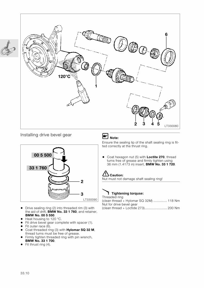
Installing drive bevel gear
• Drive sealing ring (2) into threaded rim (3) with the aid of drift, BMW No. 33 1 760, and retainer, BMW No. 00 5 550.
• Heat housing to 120 °C.• Fit drive bevel gear complete with spacer (1).• Fit outer race (6).• Coat threaded ring (3) with Hylomar SQ 32 M,
thread turns must be free of grease.• Firmly tighten threaded ring with pin wrench,
BMW No. 33 1 700.• Fit thrust ring (4).
L Note:Ensure the sealing lip of the shaft sealing ring is fit-ted correctly at the thrust ring.
• Coat hexagon nut (5) with Loctite 270, thread turns free of grease and firmly tighten using 36 mm (1.4173 in) insert, BMW No. 33 1 720.
e Caution:Nut must not damage shaft sealing ring!
X Tightening torquse:Threaded ring (clean thread + Hylomar SQ 32M) .............. 118 NmNut for drive bevel gear (clean thread + Loctide 273)....................... 200 Nm
LT330080
120°C
1
6
2 3 4 5
00 5 500
LT330090
33 1 760
2
3
33.10
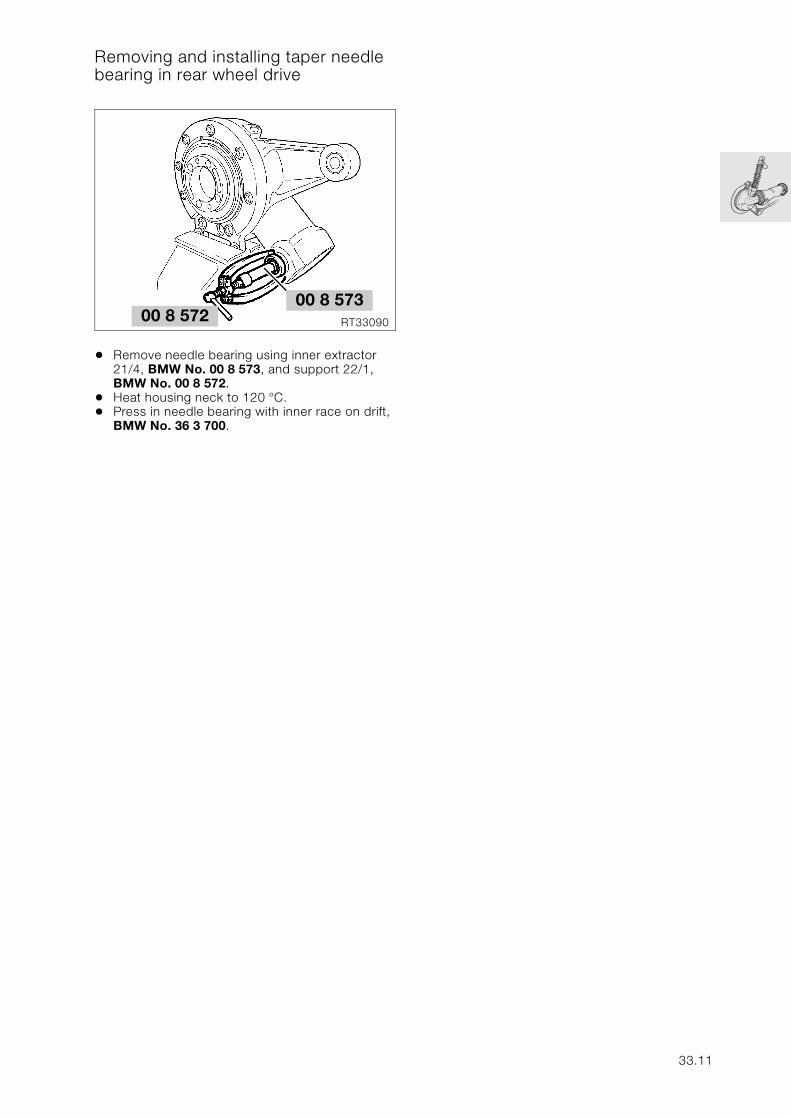
Removing and installing taper needle bearing in rear wheel drive
• Remove needle bearing using inner extractor21/4, BMW No. 00 8 573, and support 22/1, BMW No. 00 8 572.
• Heat housing neck to 120 °C.• Press in needle bearing with inner race on drift,
BMW No. 36 3 700.
RT3309000 8 57200 8 573
33.11
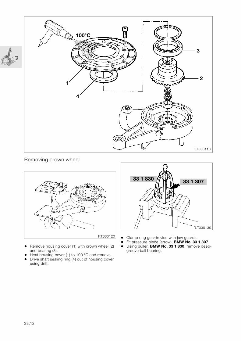
Removing crown wheel
• Remove housing cover (1) with crown wheel (2) and bearing (3).
• Heat housing cover (1) to 100 °C and remove.• Drive shaft sealing ring (4) out of housing cover
using drift.
• Clamp ring gear in vice with jaw guards.• Fit pressure piece (arrow), BMW No. 33 1 307.• Using puller, BMW No. 33 1 830, remove deep-
groove ball bearing.
LT330110
1
3
2
4
100°C
RT330120
33 1 830
LT330130
33 1 307
33.12
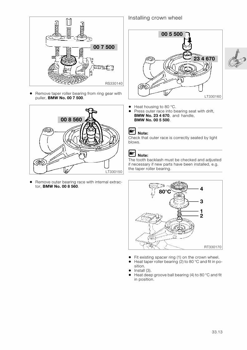
• Remove taper roller bearing from ring gear with puller, BMW No. 00 7 500.
• Remove outer bearing race with internal extrac-tor, BMW No. 00 8 560.
Installing crown wheel
• Heat housing to 80 °C.• Press outer race into bearing seat with drift,
BMW No. 23 4 670, and handle, BMW No. 00 5 500.
L Note:Check that outer race is correctly seated by light blows.
L Note:The tooth backlash must be checked and adjusted if necessary if new parts have been installed, e.g. the taper roller bearing.
• Fit existing spacer ring (1) on the crown wheel.• Heat taper roller bearing (2) to 80 °C and fit in po-
sition.• Install (3).• Heat deep groove ball bearing (4) to 80 °C and fit
in position.
00 7 500
RS330140
00 8 560
LT330150
23 4 670
LT330160
00 5 500
RT330170
80°C 4
3
12
33.13
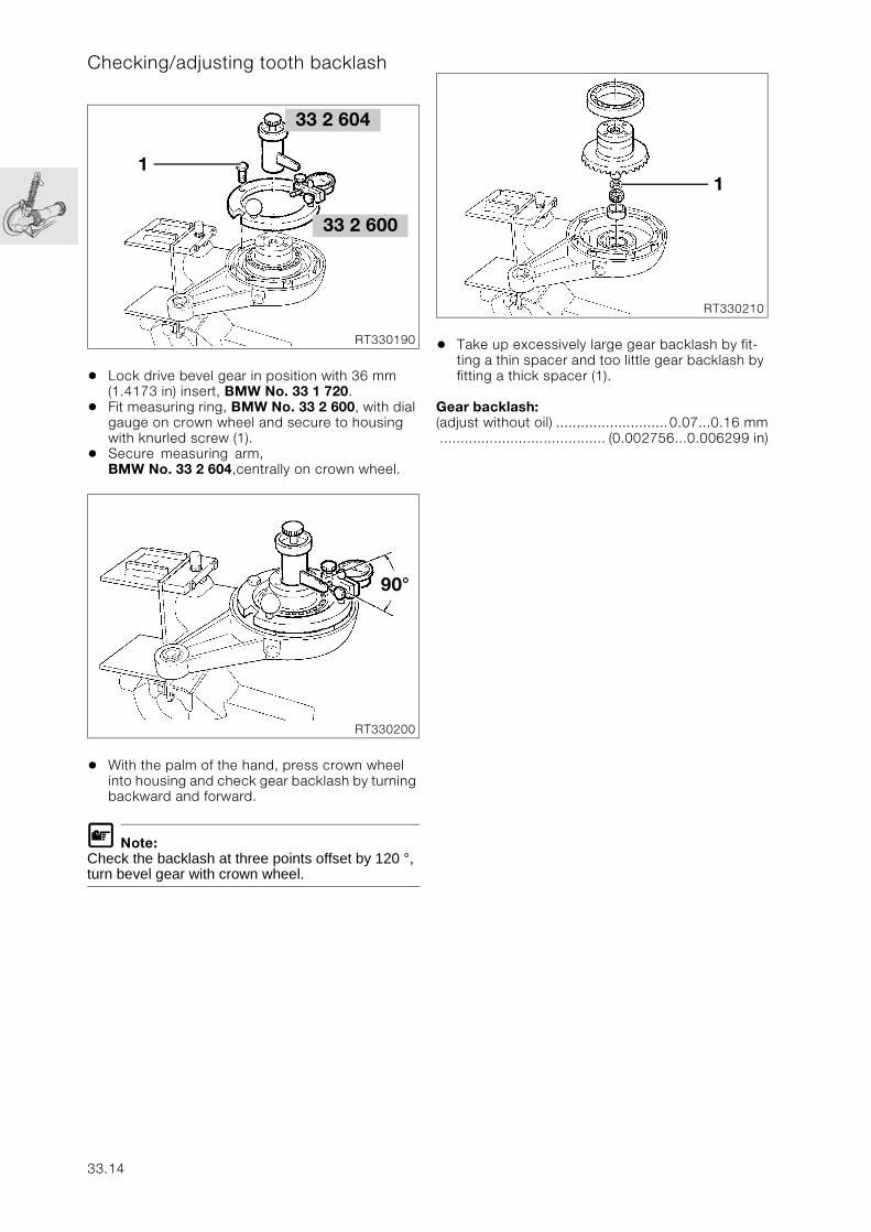
Checking/adjusting tooth backlash
• Lock drive bevel gear in position with 36 mm (1.4173 in) insert, BMW No. 33 1 720.
• Fit measuring ring, BMW No. 33 2 600, with dial gauge on crown wheel and secure to housing with knurled screw (1).
• Secure measuring arm, BMW No. 33 2 604,centrally on crown wheel.
• With the palm of the hand, press crown wheel into housing and check gear backlash by turning backward and forward.
L Note:Check the backlash at three points offset by 120 °, turn bevel gear with crown wheel.
• Take up excessively large gear backlash by fit-ting a thin spacer and too little gear backlash by fitting a thick spacer (1).
Gear backlash:(adjust without oil) ...........................0.07...0.16 mm........................................ (0.002756...0.006299 in)
33 2 604
RT330190
1
33 2 600
RT330200
90°
RT330210
1
33.14
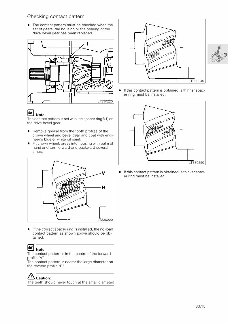
Checking contact pattern
• The contact pattern must be checked when the set of gears, the housing or the bearing of the drive bevel gear has been replaced.
L Note:The contact pattern is set with the spacer ring?(1) on the drive bevel gear.
• Remove grease from the tooth profiles of the crown wheel and bevel gear and coat with engi-neer’s blue or white oil paint.
• Fit crown wheel, press into housing with palm of hand and turn forward and backward several times.
• If the correct spacer ring is installed, the no-load contact pattern as shown above should be ob-tained.
L Note:The contact pattern is in the centre of the forward profile “V”.The contact pattern is nearer the large diameter on the reverse profile “R”.
e Caution:The teeth should never touch at the small diameter!
• If this contact pattern is obtained, a thinner spac-er ring must be installed.
• If this contact pattern is obtained, a thicker spac-er ring must be installed.
LT330220
1
LT330220
R
V
LT330240
LT330250
33.15
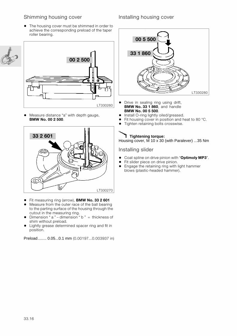
Shimming housing cover
• The housing cover must be shimmed in order to achieve the corresponding preload of the taper roller bearing.
• Measure distance “a” with depth gauge, BMW No. 00 2 500.
• Fit measuring ring (arrow), BMW No. 33 2 601• Measure from the outer race of the ball bearing
to the parting surface of the housing through the cutout in the measuring ring.
• Dimension “ a ” – dimension “ b ” = thickness of shim without preload.
• Lightly grease determined spacer ring and fit in position.
Preload........ 0.05...0.1 mm (0.00197...0.003937 in)
Installing housing cover
• Drive in sealing ring using drift, BMW No. 33 1 860, and handle BMW No. 00 5 500.
• Install O-ring lightly oiled/greased.• Fit housing cover in position and heat to 80 °C. • Tighten retaining bolts crosswise.
X Tightening torque:Housing cover, M 10 x 30 (with Paralever) ...35 Nm
Installing slider
• Coat spline on drive pinion with “Optimoly MP3”.• Fit slider piece on drive pinion.• Engage the retaining ring with light hammer
blows (plastic-headed hammer).
00 2 500
LT330260
33 2 601
LT330270
00 5 500
LT330280
33 1 860
33.16
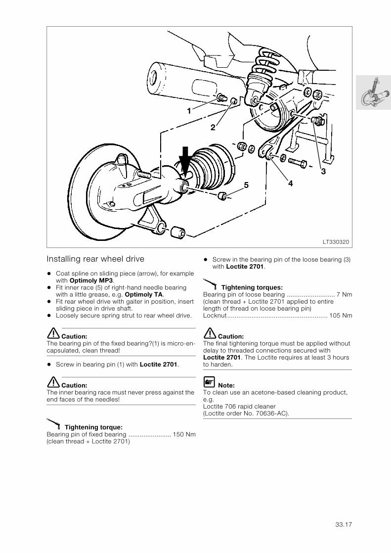
Installing rear wheel drive
• Coat spline on sliding piece (arrow), for example with Optimoly MP3.
• Fit inner race (5) of right-hand needle bearing with a little grease, e.g. Optimoly TA.
• Fit rear wheel drive with gaiter in position, insert sliding piece in drive shaft.
• Loosely secure spring strut to rear wheel drive.
e Caution:The bearing pin of the fixed bearing?(1) is micro-en-capsulated, clean thread!
• Screw in bearing pin (1) with Loctite 2701.
e Caution:The inner bearing race must never press against the end faces of the needles!
X Tightening torque:Bearing pin of fixed bearing ....................... 150 Nm(clean thread + Loctite 2701)
• Screw in the bearing pin of the loose bearing (3) with Loctite 2701.
X Tightening torques:Bearing pin of loose bearing .......................... 7 Nm(clean thread + Loctite 2701 applied to entire length of thread on loose bearing pin)Locknut...................................................... 105 Nm
e Caution:The final tightening torque must be applied without delay to threaded connections secured with Loctite 2701. The Loctite requires at least 3 hours to harden.
L Note:To clean use an acetone-based cleaning product, e.g.Loctite 706 rapid cleaner(Loctite order No. 70636-AC).
LT330320
1
4
2
5
3
33.17
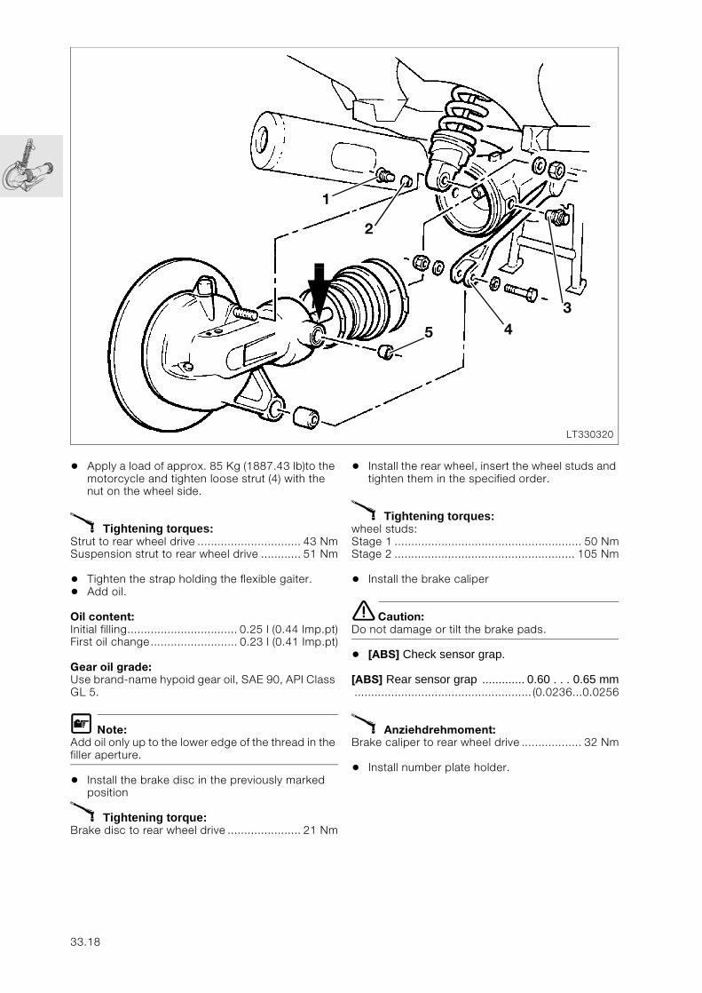
• Apply a load of approx. 85 Kg (1887.43 lb)to the motorcycle and tighten loose strut (4) with the nut on the wheel side.
X Tightening torques:Strut to rear wheel drive ............................... 43 NmSuspension strut to rear wheel drive ............ 51 Nm
• Tighten the strap holding the flexible gaiter.• Add oil.
Oil content:Initial filling................................. 0.25 l (0.44 Imp.pt)First oil change.......................... 0.23 l (0.41 Imp.pt)
Gear oil grade:Use brand-name hypoid gear oil, SAE 90, API Class GL 5.
L Note:Add oil only up to the lower edge of the thread in the filler aperture.
• Install the brake disc in the previously marked position
X Tightening torque:Brake disc to rear wheel drive ...................... 21 Nm
• Install the rear wheel, insert the wheel studs and tighten them in the specified order.
X Tightening torques:wheel studs:Stage 1 ........................................................ 50 NmStage 2 ...................................................... 105 Nm
• Install the brake caliper
e Caution:Do not damage or tilt the brake pads.
• [ABS] Check sensor grap.
[ABS] Rear sensor grap ............. 0.60 . . . 0.65 mm..................................................... (0.0236...0.0256
X Anziehdrehmoment:Brake caliper to rear wheel drive .................. 32 Nm
• Install number plate holder.
LT330320
1
4
2
5
3
33.18
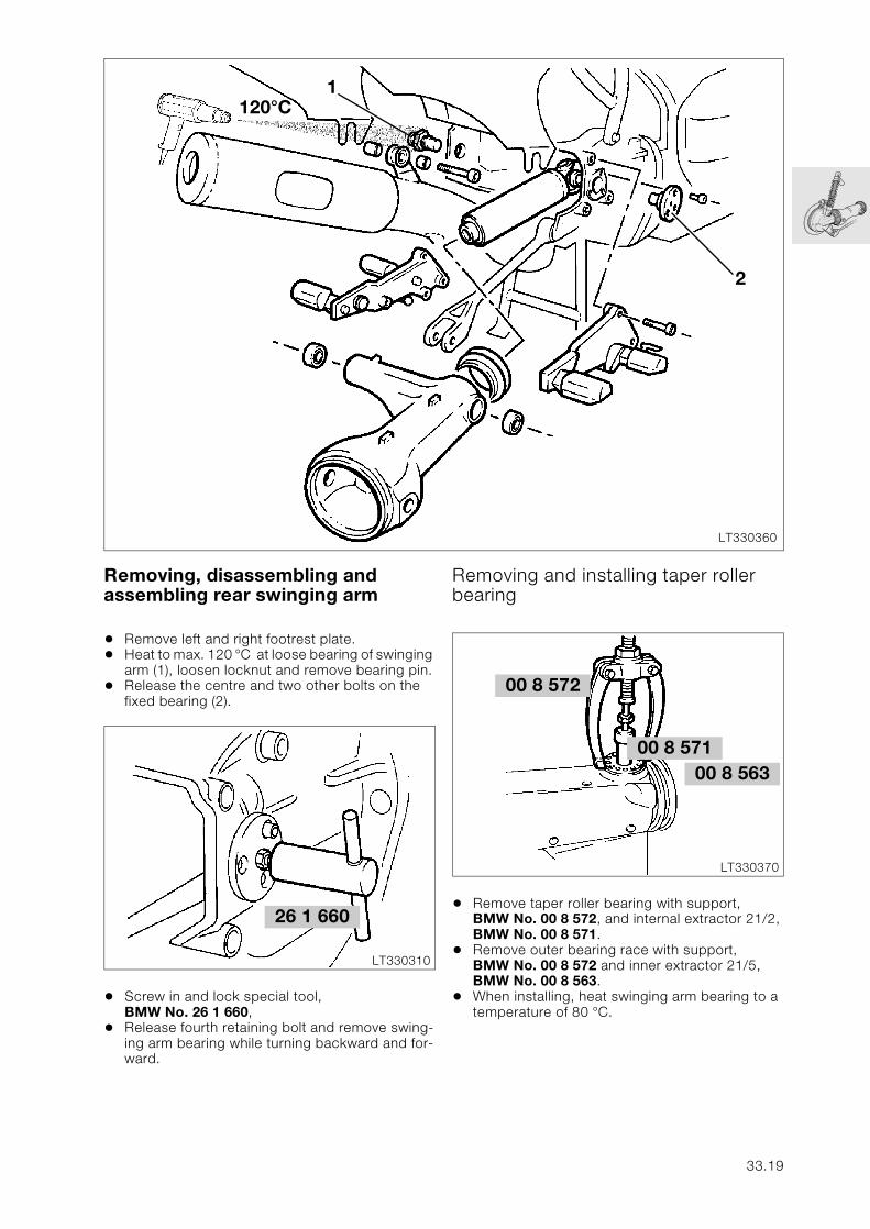
Removing, disassembling and assembling rear swinging arm
• Remove left and right footrest plate.• Heat to max. 120 °C at loose bearing of swinging
arm (1), loosen locknut and remove bearing pin.• Release the centre and two other bolts on the
fixed bearing (2).
• Screw in and lock special tool, BMW No. 26 1 660,
• Release fourth retaining bolt and remove swing-ing arm bearing while turning backward and for-ward.
Removing and installing taper roller bearing
• Remove taper roller bearing with support, BMW No. 00 8 572, and internal extractor 21/2, BMW No. 00 8 571.
• Remove outer bearing race with support, BMW No. 00 8 572 and inner extractor 21/5, BMW No. 00 8 563.
• When installing, heat swinging arm bearing to a temperature of 80 °C.
LT330360
120°C
2
1
26 1 660
LT330310
00 8 572
LT330370
00 8 56300 8 571
33.19
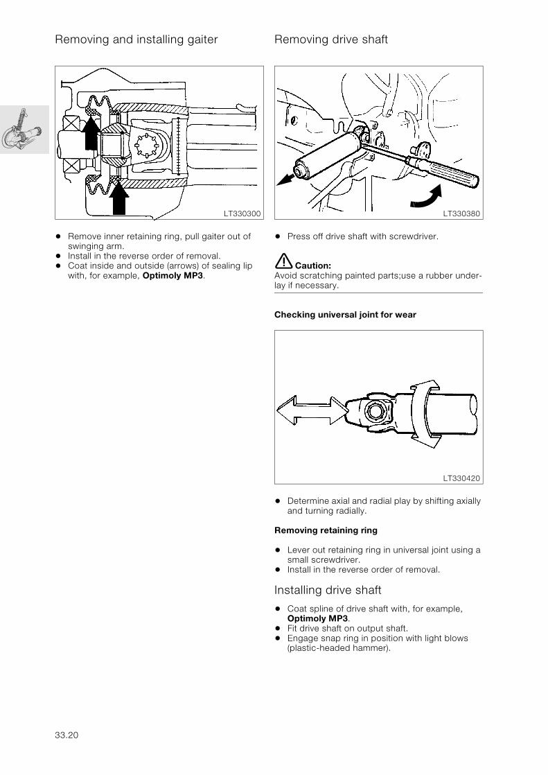
Removing and installing gaiter
• Remove inner retaining ring, pull gaiter out of swinging arm.
• Install in the reverse order of removal.• Coat inside and outside (arrows) of sealing lip
with, for example, Optimoly MP3.
Removing drive shaft
• Press off drive shaft with screwdriver.
e Caution:Avoid scratching painted parts;use a rubber under-lay if necessary.
Checking universal joint for wear
• Determine axial and radial play by shifting axially and turning radially.
Removing retaining ring
• Lever out retaining ring in universal joint using a small screwdriver.
• Install in the reverse order of removal.
Installing drive shaft
• Coat spline of drive shaft with, for example, Optimoly MP3.
• Fit drive shaft on output shaft.• Engage snap ring in position with light blows
(plastic-headed hammer).
LT330300 LT330380
LT330420
33.20
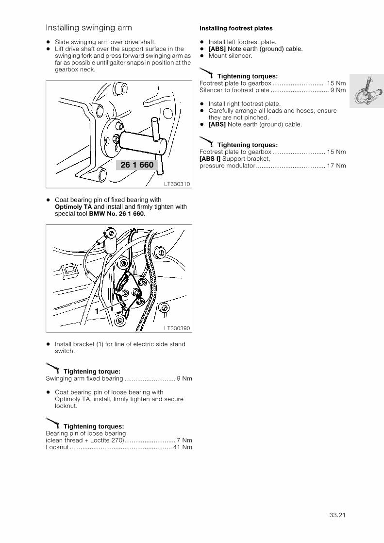
Installing swinging arm
• Slide swinging arm over drive shaft.• Lift drive shaft over the support surface in the
swinging fork and press forward swinging arm as far as possible until gaiter snaps in position at the gearbox neck.
• Coat bearing pin of fixed bearing with Optimoly TA and install and firmly tighten with special tool BMW No. 26 1 660.
• Install bracket (1) for line of electric side stand switch.
X Tightening torque:Swinging arm fixed bearing ............................ 9 Nm
• Coat bearing pin of loose bearing with Optimoly TA, install, firmly tighten and secure locknut.
X Tightening torques:Bearing pin of loose bearing (clean thread + Loctite 270)............................ 7 NmLocknut........................................................ 41 Nm
Installing footrest plates
• Install left footrest plate.• [ABS] Note earth (ground) cable.• Mount silencer.
X Tightening torques: Footrest plate to gearbox ............................ 15 NmSilencer to footrest plate ................................ 9 Nm
• Install right footrest plate.• Carefully arrange all leads and hoses; ensure
they are not pinched.• [ABS] Note earth (ground) cable.
X Tightening torques:Footrest plate to gearbox ............................. 15 Nm[ABS I] Support bracket, pressure modulator...................................... 17 Nm26 1 660
LT330310
LT330390
1
33.21

33.22
34
Contents Page
34 Brakes
Technical Data ............................................................................................................................... 3
Removing and installing front brake caliper .................................................................5
Dismantling and assembling front brake caliper ........................................................6
Dismantling front brake caliper .................................................................................................6
Assembling front brake caliper .................................................................................................7
Removing and installing brake pads ......................................................................................8
Removing and installing front brake disc .......................................................................9
Removing and installing ABS pulse wheel ..........................................................................9
Removing and installing front ABS sensor ..................................................................10
Adjusting front ABS sensor gap .........................................................................................11
Removing and installing front brake line .......................................................................12
Removing upper brake line .......................................................................................................12
Removing lower brake line ........................................................................................................12
Removing and installing ABS brake line from front pressure modulator ...13
Removing and installing handbrake cylinder .............................................................14
Bleeding brake .............................................................................................................................15
Bleeding front brake ....................................................................................................................15Bleeding brake caliper .......................................................................................................................15[ABS II] Bleeding pressure modulator ................................................................................................16Bleeding the handlebar fitting ............................................................................................................16
Bleeding rear brake ......................................................................................................................16Bleeding brake caliper .......................................................................................................................16[ABS II] Bleeding pressure modulator ................................................................................................16
Removing and installing pressure modulator .............................................................17
[ABS I] Removing and installing front or rear pressure modulator ..........................17
[ABS II] Removing ABS unit ......................................................................................................18
34.1
Contents Page
[ABS II] Installing ABS unit ........................................................................................................19
[ABS II] Removing and installing relay and relay base ..........................................20
[ABS II] Removing relay ..............................................................................................................20
[ABS II] Installing relay ................................................................................................................20
[ABS II] Removing relay base ..................................................................................................21
[ABS II] Installing relay base .....................................................................................................21
Removing and installing rear brake caliper .................................................................22
Removing and installing rear brake pads .....................................................................22
Dismantling and assembling rear brake caliper .......................................................23
Dismantling rear brake caliper ................................................................................................23
Assembling rear brake caliper .................................................................................................23
Removing and installing rear brake disc .......................................................................24
Removing and installing rear ABS sensor ....................................................................25
Measuring vertical runout at rear pulse wheel ..........................................................26
Removing and installing rear master brake cylinder ..............................................27
Disassembling rear master brake cylinder ........................................................................28
Removing and installing brake pedal ..............................................................................29
Adjusting foot brake pedal ....................................................................................................30
Troubleshooting: Front wheel/rear wheel brake ......................................................31
34.2
34
Technical Data K 1100 LT K 1100 RS
Brake fluid DOT 4
Minimum brake pad thickness mm (in) 1.5 (0.059)
Front wheel
Brake disc Ø mm (in) 305 (12.01)
Brake disc thickness mm (in) 5± 0.1 (0.197 ± 0.0039)
Minimum thickness mm (in) 4.5 (0.177)
Brake pad surface cm2 (in2) 100 (15.5)
Piston Ø of brake caliper mm (in) 32/34 (1.26/1.34)
Piston Ø handbrake cylinder mm (in) 20 (0.79)
ABS front sensor gap(measured at max. distance point)
mm (in) 0.50...0.55 (0.0197...0.0216) Up to 1996 MY0.45...0.55 (0.0177...0.0216) From 1997 MY
Rear wheel
Brake disc Ø mm (in) 285 (11.22)
Brake disc thickness mm (in) 5± 0,2 (0.197 ± 0.00787)
Minimum thickness mm (in) 4.6 (0.181)
Permissible lateral runout mm (in) 0.2 (0.0078)
Brake pad surface cm2 (in2) 41.5 (6.43)
Piston Ø brake caliper mm (in) 38 (1.496)
Piston Ø foot brake cylinder mm (in) 12 (0.472)
ABS rear sensor gap(measured at max. distance point)
mm (in) 0.60...0.65 (0.0236...0.0256) Up to 1996 MY0.45...0.55 (0.0177...0.0216) From 1997 MY
34.3

34.4
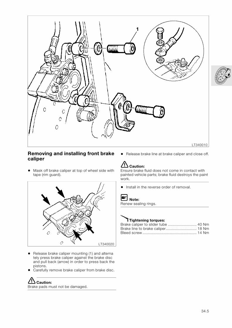
Removing and installing front brake caliper
• Mask off brake caliper at top of wheel side with tape (rim guard).
• Release brake caliper mounting (1) and alterna tely press brake caliper against the brake disc and pull back (arrow) in order to press back the pistons.
• Carefully remove brake caliper from brake disc.
e Caution:Brake pads must not be damaged.
• Release brake line at brake caliper and close off.
e Caution:Ensure brake fluid does not come in contact with painted vehicle parts; brake fluid destroys the paint work.
• Install in the reverse order of removal.
L Note:Renew sealing rings.
X Tightening torques:Brake caliper to slider tube .......................... 40 NmBrake line to brake caliper............................ 18 NmBleed screw ................................................. 14 Nm
LT340010
1
LT340020
34.5
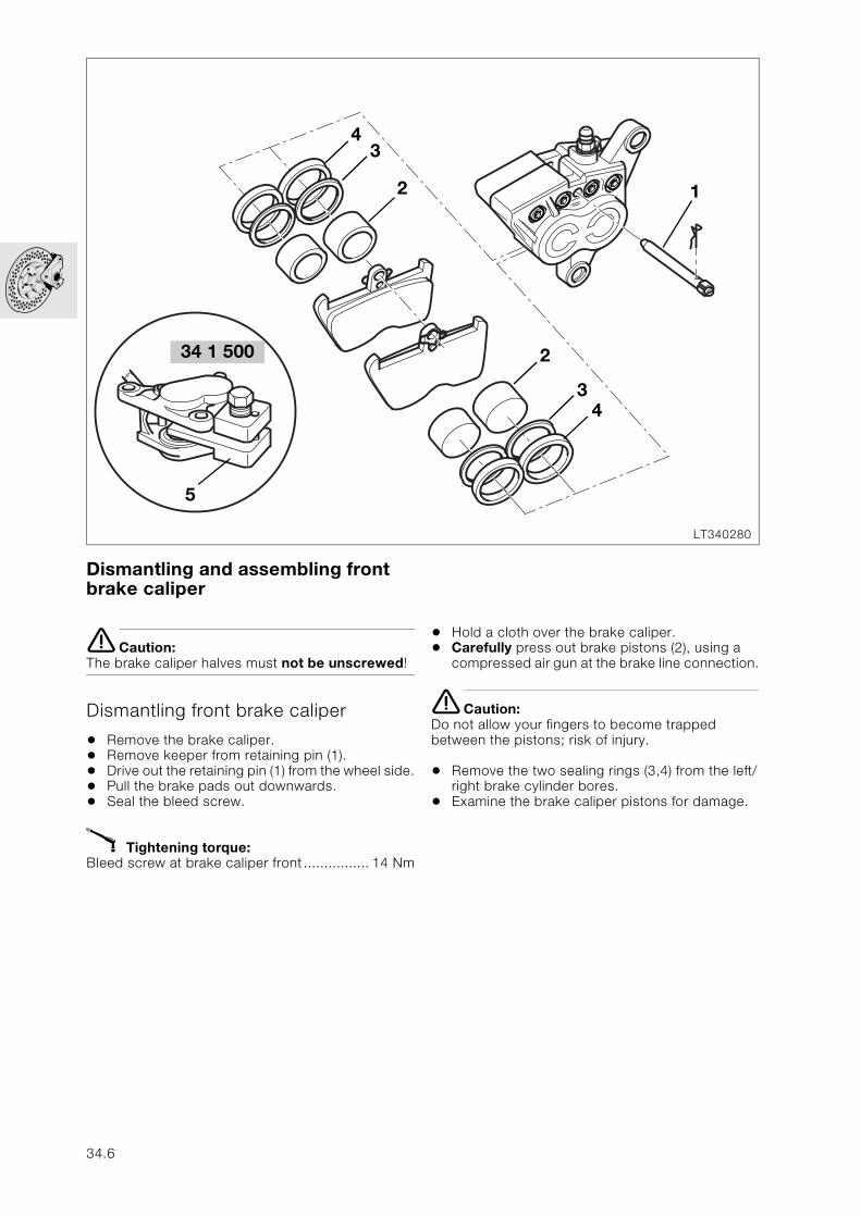
Dismantling and assembling front brake caliper
e Caution:The brake caliper halves must not be unscrewed!
Dismantling front brake caliper
• Remove the brake caliper.• Remove keeper from retaining pin (1).• Drive out the retaining pin (1) from the wheel side.• Pull the brake pads out downwards.• Seal the bleed screw.
X Tightening torque:Bleed screw at brake caliper front ................ 14 Nm
• Hold a cloth over the brake caliper.• Carefully press out brake pistons (2), using a
compressed air gun at the brake line connection.
e Caution:Do not allow your fingers to become trapped between the pistons; risk of injury.
• Remove the two sealing rings (3,4) from the left/right brake cylinder bores.
• Examine the brake caliper pistons for damage.
LT340280
34 1 500
5
2
43
1
2
34
34.6
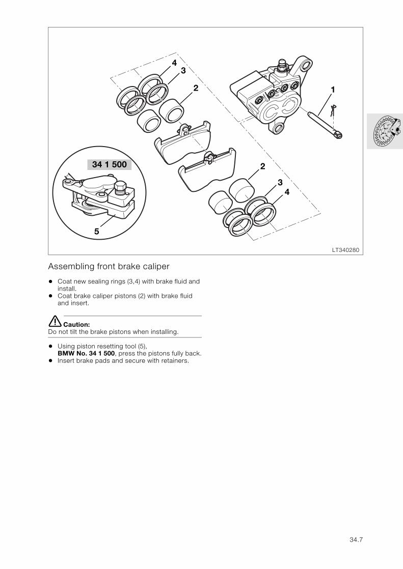
Assembling front brake caliper
• Coat new sealing rings (3,4) with brake fluid and install.
• Coat brake caliper pistons (2) with brake fluid and insert.
e Caution:Do not tilt the brake pistons when installing.
• Using piston resetting tool (5),BMW No. 34 1 500, press the pistons fully back.
• Insert brake pads and secure with retainers.
LT340280
34 1 500
5
2
43
1
2
34
34.7
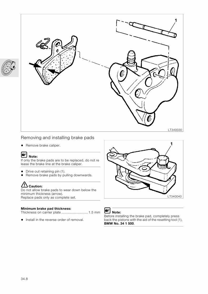
Removing and installing brake pads
• Remove brake caliper.
L Note:If only the brake pads are to be replaced, do not re lease the brake line at the brake caliper.
• Drive out retaining pin (1).• Remove brake pads by pulling downwards.
e Caution:Do not allow brake pads to wear down below the minimum thickness (arrow).Replace pads only as complete set.
Minimum brake pad thickness:Thickness on carrier plate ...........................1.5 mm
• Install in the reverse order of removal.
L Note:Before installing the brake pad, completely press back the pistons with the aid of the resetting tool (1), BMW No. 34 1 500.
LT340030
1
LT340040
1
34.8
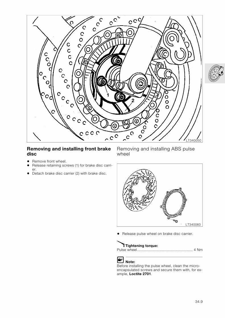
Removing and installing front brake disc
• Remove front wheel.• Release retaining screws (1) for brake disc carri-
er.• Detach brake disc carrier (2) with brake disc.
Removing and installing ABS pulse wheel
• Release pulse wheel on brake disc carrier.
X Tightening torque:Pulse wheel.................................................... 4 Nm
L Note:Before installing the pulse wheel, clean the micro-encapsulated screws and secure them with, for ex-ample, Loctite 2701.
LT340050
12
LT340060
34.9
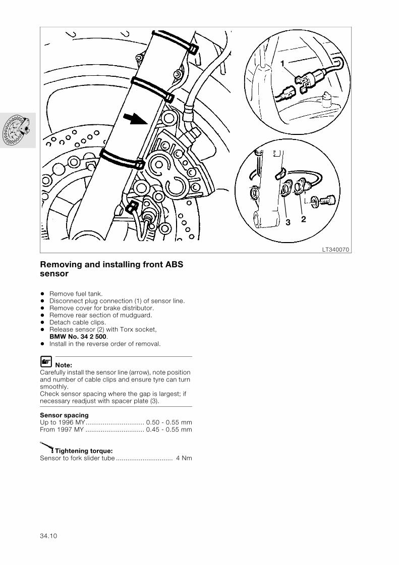
Removing and installing front ABS sensor
• Remove fuel tank.• Disconnect plug connection (1) of sensor line.• Remove cover for brake distributor.• Remove rear section of mudguard.• Detach cable clips.• Release sensor (2) with Torx socket,
BMW No. 34 2 500.• Install in the reverse order of removal.
L Note:Carefully install the sensor line (arrow), note position and number of cable clips and ensure tyre can turn smoothly.Check sensor spacing where the gap is largest; if necessary readjust with spacer plate (3).
Sensor spacingUp to 1996 MY............................... 0.50 - 0.55 mmFrom 1997 MY ............................... 0.45 - 0.55 mm
X Tightening torque:Sensor to fork slider tube .............................. 4 Nm
LT340070
1
3 2
34.10

Adjusting front ABS sensor gap
• Raise front wheel with front wheel stand, BMW No. 36 3 950.
• Secure dial gauge holder (1), BMW No. 34 2 520 with dial gauge to fork sliding tube.
• Secure measuring shoe (2), BMW No. 34 2 510 to feeler of dial gauge.
• Set dial gauge at marking (arrow) on pulse wheel to zero.
• Measure axial runout over the entire circumfe rence.
• Adjust the sensor spacing with spacer plates at the point with the least pointer deflection.
• Remove and install sensor using Torx socket, BMW No 34 2 500.
Sensor spacing front:Up to 1996 MY .............................. 0.50 - 0.55 mm ................................................ (0.0197...0.0216 in)From 1997 MY on .......................... 0.45 - 0.55 mm ................................................ (0.0177...0.0216 in)
e Caution:After adjustment, check that the sensor is clear over the entire circumference.
L Note:If the pulse wheel has been replaced, its maximum axial runout must be determined; mark point with coloured dot.
LT340080
1
2
34 2 520
34 2 510
34.11
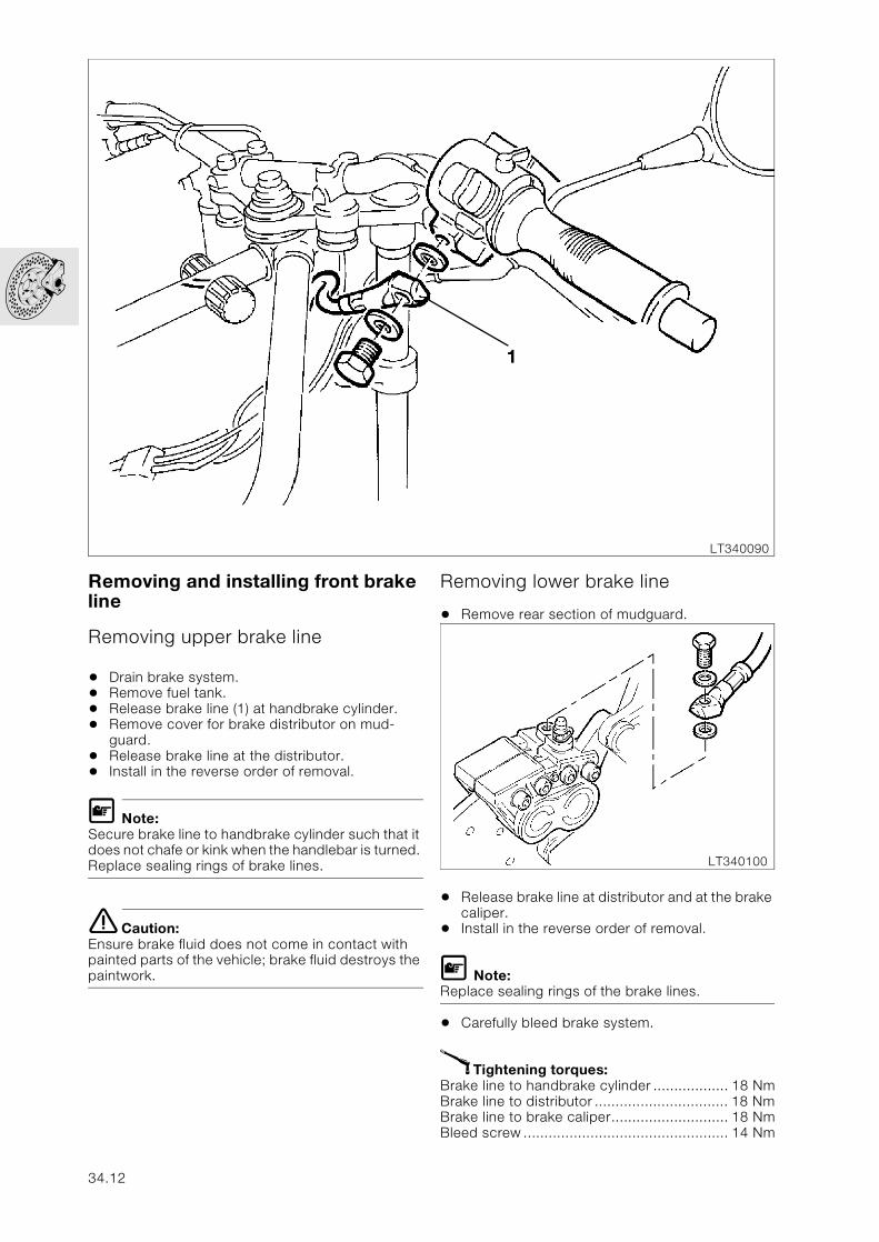
Removing and installing front brake line
Removing upper brake line
• Drain brake system.• Remove fuel tank.• Release brake line (1) at handbrake cylinder.• Remove cover for brake distributor on mud-
guard.• Release brake line at the distributor.• Install in the reverse order of removal.
L Note:Secure brake line to handbrake cylinder such that it does not chafe or kink when the handlebar is turned. Replace sealing rings of brake lines.
e Caution:Ensure brake fluid does not come in contact with painted parts of the vehicle; brake fluid destroys the paintwork.
Removing lower brake line
• Remove rear section of mudguard.
• Release brake line at distributor and at the brake caliper.
• Install in the reverse order of removal.
L Note:Replace sealing rings of the brake lines.
• Carefully bleed brake system.
X Tightening torques:Brake line to handbrake cylinder .................. 18 NmBrake line to distributor ................................ 18 NmBrake line to brake caliper............................ 18 NmBleed screw ................................................. 14 Nm
LT340090
1
LT340100
34.12
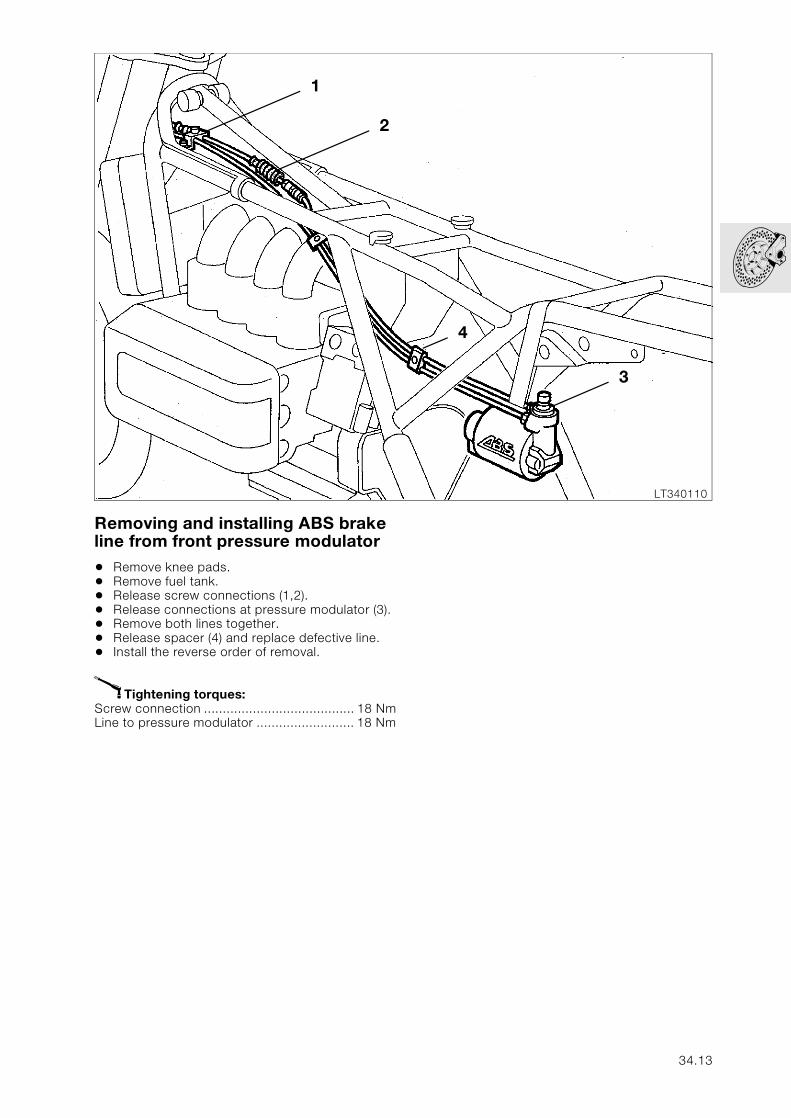
Removing and installing ABS brake line from front pressure modulator
• Remove knee pads.• Remove fuel tank.• Release screw connections (1,2).• Release connections at pressure modulator (3).• Remove both lines together.• Release spacer (4) and replace defective line.• Install the reverse order of removal.
X Tightening torques:Screw connection ........................................ 18 NmLine to pressure modulator .......................... 18 Nm
LT340110
1
2
3
4
34.13
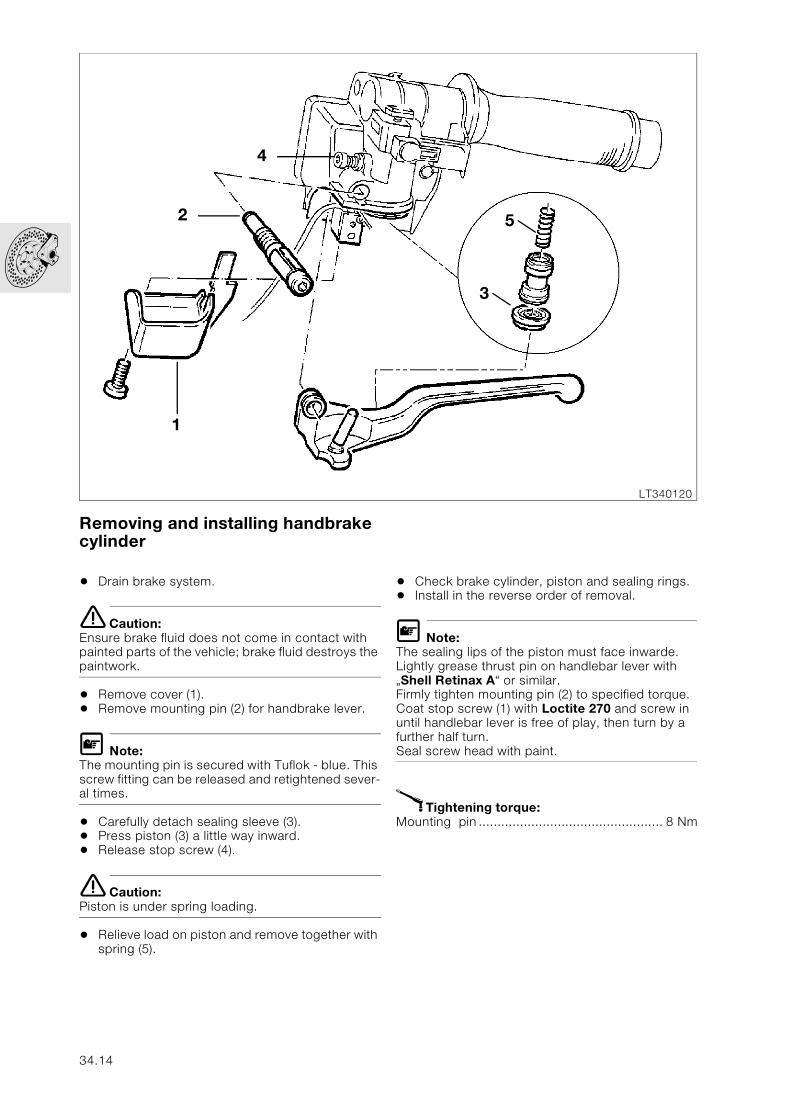
Removing and installing handbrake cylinder
• Drain brake system.
e Caution:Ensure brake fluid does not come in contact with painted parts of the vehicle; brake fluid destroys the paintwork.
• Remove cover (1).• Remove mounting pin (2) for handbrake lever.
L Note:The mounting pin is secured with Tuflok - blue. This screw fitting can be released and retightened sever-al times.
• Carefully detach sealing sleeve (3).• Press piston (3) a little way inward.• Release stop screw (4).
e Caution:Piston is under spring loading.
• Relieve load on piston and remove together with spring (5).
• Check brake cylinder, piston and sealing rings.• Install in the reverse order of removal.
L Note:The sealing lips of the piston must face inwarde. Lightly grease thrust pin on handlebar lever with „Shell Retinax A“ or similar.Firmly tighten mounting pin (2) to specified torque.Coat stop screw (1) with Loctite 270 and screw in until handlebar lever is free of play, then turn by a further half turn.Seal screw head with paint.
X Tightening torque:Mounting pin ................................................. 8 Nm
LT340120
1
2
4
3
5
34.14
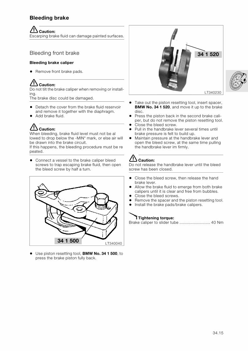
Bleeding brake
e Caution:Escarping brake fluid can damage painted surfaces.
Bleeding front brake
Bleeding brake caliper
• Remove front brake pads.
e Caution:Do not tilt the brake caliper when removing or install-ing. The brake disc could be damaged.
• Detach the cover from the brake fluid reservoir and remove it together with the diaphragm.
• Add brake fluid.
e Caution:When bleeding, brake fluid level must not be al lowed to drop below the -MIN“ mark, or else air will be drawn into the brake circuit.If this happens, the bleeding procedure must be re peated.
• Connect a vessel to the brake caliper bleed screws to trap escaping brake fluid, then open the bleed screw by half a turn.
• Use piston resetting tool, BMW No. 34 1 500, to press the brake piston fully back.
• Take out the piston resetting tool, insert spacer, BMW No. 34 1 520, and move it up to the brake disc.
• Press the piston back in the second brake cali-per, but do not remove the piston resetting tool.
• Close the bleed screw.• Pull in the handbrake lever several times until
brake pressure is felt to build up.• Maintain pressure at the handbrake lever and
open the bleed screw, at the same time pulling the handbrake lever im firmly.
e Caution:Do not release the handbrake lever until the bleed screw has been closed.
• Close the bleed screw, then release the hand brake lever.
• Allow the brake fluid to emerge from both brake calipers until it is clear and free from bubbles.
• Close the bleed screws.• Remove the spacer and the piston resetting tool.• Install the brake pads/brake calipers.
X Tightening torque:Brake caliper to slider tube .......................... 40 Nm
LT34004034 1 500
LT340230
34 1 520
34.15
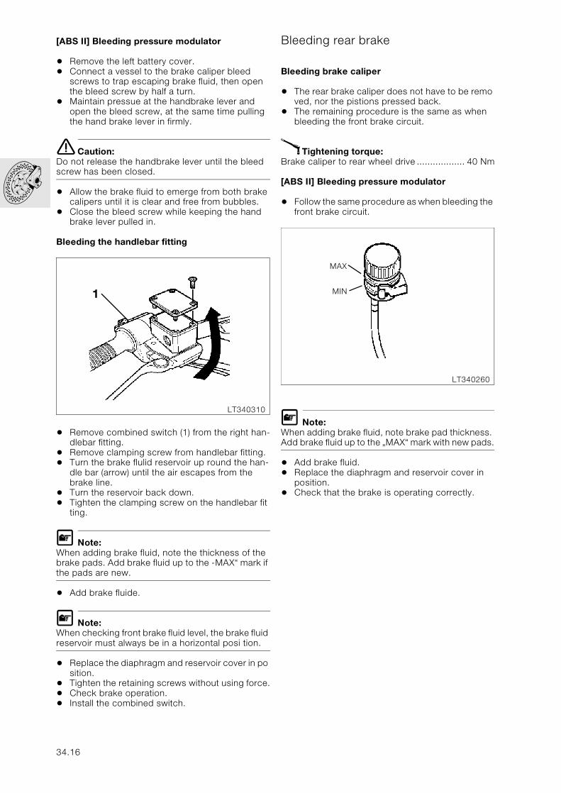
[ABS II] Bleeding pressure modulator
• Remove the left battery cover.• Connect a vessel to the brake caliper bleed
screws to trap escaping brake fluid, then open the bleed screw by half a turn.
• Maintain pressue at the handbrake lever and open the bleed screw, at the same time pulling the hand brake lever in firmly.
e Caution:Do not release the handbrake lever until the bleed screw has been closed.
• Allow the brake fluid to emerge from both brake calipers until it is clear and free from bubbles.
• Close the bleed screw while keeping the hand brake lever pulled in.
Bleeding the handlebar fitting
• Remove combined switch (1) from the right han-dlebar fitting.
• Remove clamping screw from handlebar fitting.• Turn the brake flulid reservoir up round the han-
dle bar (arrow) until the air escapes from the brake line.
• Turn the reservoir back down.• Tighten the clamping screw on the handlebar fit
ting.
L Note:When adding brake fluid, note the thickness of the brake pads. Add brake fluid up to the -MAX“ mark if the pads are new.
• Add brake fluide.
L Note:When checking front brake fluid level, the brake fluid reservoir must always be in a horizontal posi tion.
• Replace the diaphragm and reservoir cover in po sition.
• Tighten the retaining screws without using force.• Check brake operation.• Install the combined switch.
Bleeding rear brake
Bleeding brake caliper
• The rear brake caliper does not have to be remo ved, nor the pistions pressed back.
• The remaining procedure is the same as when bleeding the front brake circuit.
X Tightening torque:Brake caliper to rear wheel drive .................. 40 Nm
[ABS II] Bleeding pressure modulator
• Follow the same procedure as when bleeding the front brake circuit.
L Note:When adding brake fluid, note brake pad thickness. Add brake fluid up to the „MAX“ mark with new pads.
• Add brake fluid.• Replace the diaphragm and reservoir cover in
position.• Check that the brake is operating correctly.
LT340310
1
LT340260
MAX
MIN
34.16
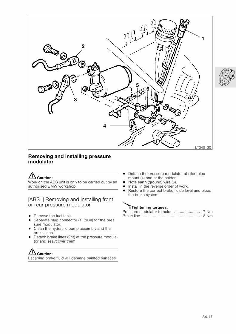
Removing and installing pressure modulator
e Caution:Work on the ABS unit is only to be carried out by an authorised BMW workshop.
[ABS I] Removing and installing front or rear pressure modulator
• Remove the fuel tank.• Separate plug connector (1) (blue) for the pres
sure modulator.• Clean the hydraulic pump assembly and the
brake lines.• Detach brake lines (2/3) at the pressure modula-
tor and seal/cover them.
e Caution:Escaping brake fluid will damage painted surfaces.
• Detach the pressure modulator at silentbloc mount (4) and at the holder.
• Note earth (ground) wire (6).• Install in the reverse order of work.• Restore the correct brake fluide level and bleed
the brake system.
X Tightening torques:Pressure modulator to holder....................... 17 NmBrake line..................................................... 18 Nm
LT340130
1
2
3
4
56
34.17
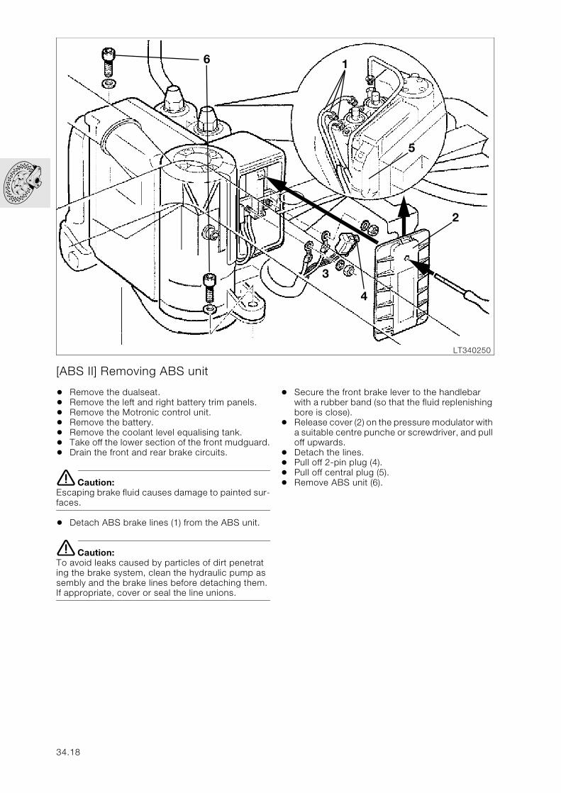
[ABS II] Removing ABS unit
• Remove the dualseat.• Remove the left and right battery trim panels.• Remove the Motronic control unit.• Remove the battery.• Remove the coolant level equalising tank.• Take off the lower section of the front mudguard.• Drain the front and rear brake circuits.
e Caution:Escaping brake fluid causes damage to painted sur-faces.
• Detach ABS brake lines (1) from the ABS unit.
e Caution:To avoid leaks caused by particles of dirt penetrat ing the brake system, clean the hydraulic pump as sembly and the brake lines before detaching them. If appropriate, cover or seal the line unions.
• Secure the front brake lever to the handlebar with a rubber band (so that the fluid replenishing bore is close).
• Release cover (2) on the pressure modulator with a suitable centre punche or screwdriver, and pull off upwards.
• Detach the lines.• Pull off 2-pin plug (4).• Pull off central plug (5).• Remove ABS unit (6).
LT340250
6 1
5
2
3
4
34.18
[ABS II] Installing ABS unit
• Install ABS unit (6).• Reconnect central plug (5).
e Caution:Do not tilt the cables or the insulation may be dam-aged.
• Push 2-pin plug (4) on correvtly and as far as it will do, then press the two wires into the centre (smal ler) cable entries.
• Attach both plugs of the connecting cable/wiring harness to the threaded pins with the crimp fac-ing forwards.
• Press the cables into the remaining cable guides.• Tighten the nuts.
e Caution:Use new self-locking nuts.
X Tightening torques:Battery –/M5................................................ 3.5 NmBattery +/M5 ................................................. 3 Nm
• Fit a new cover.
e Caution:When sliding on, make sure that all cables are posi-tioned correctly in their guides. Always use a new cover.The old cover must be scrapped.
• Screw ABS brake lines (1) firmly to the ABS unit.• Fill/bleed the brake system.• Install the coolant level equalising tank.• Install the battery.• Install the Motronic control unit.• Install the battery covers.• Install the fuel tank.
X Tightening torques:ABS unit to mountingM6 screw ....................................................... 9 NmBrake line to ABS unit .................................. 18 NmBleed screw at ABS unit................................. 9 Nm
34.19
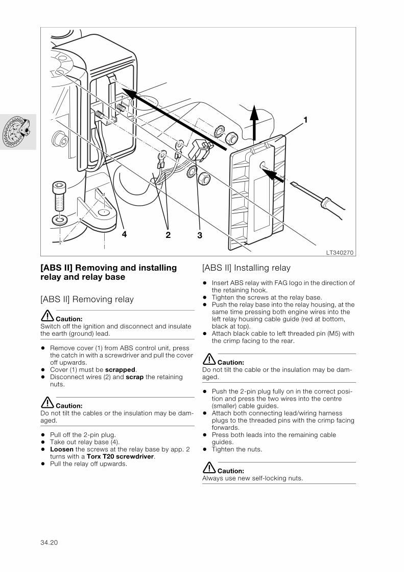
[ABS II] Removing and installing relay and relay base
[ABS II] Removing relay
e Caution:Switch off the ignition and disconnect and insulate the earth (ground) lead.
• Remove cover (1) from ABS control unit, press the catch in with a screwdriver and pull the cover off upwards.
• Cover (1) must be scrapped.• Disconnect wires (2) and scrap the retaining
nuts.
e Caution:Do not tilt the cables or the insulation may be dam-aged.
• Pull off the 2-pin plug.• Take out relay base (4).• Loosen the screws at the relay base by app. 2
turns with a Torx T20 screwdriver.• Pull the relay off upwards.
[ABS II] Installing relay
• Insert ABS relay with FAG logo in the direction of the retaining hook.
• Tighten the screws at the relay base.• Push the relay base into the relay housing, at the
same time pressing both engine wires into the left relay housing cable guide (red at bottom, black at top).
• Attach black cable to left threaded pin (M5) with the crimp facing to the rear.
e Caution:Do not tilt the cable or the insulation may be dam-aged.
• Push the 2-pin plug fully on in the correct posi-tion and press the two wires into the centre (smaller) cable guides.
• Attach both connecting lead/wiring harness plugs to the threaded pins with the crimp facing forwards.
• Press both leads into the remaining cable guides.
• Tighten the nuts.
e Caution:Always use new self-locking nuts.
LT340270
1
324
34.20
• Install a new cover (1).
e Caution:When pushing on, make sur that all cables are cor-rectly located in their guides. Scrap the old cover.
[ABS II] Removing relay base
e Caution:Switch off the ignition and disconnect and insulate the earth (ground) lead.
• Remove cover (1) from ABS control unit, press in the catch with a screwdriver and pull the cover off upwards.
• Scrap the cover.• Disconnect leads (2) and scrap the nuts.
e Caution:Do not tilt the cables or the insultation may be dam-aged.
• Pull off the 2-pin plug.• Take out relay base (4).• Take out screws on relay base with a Torx T20
screwdriver.• Remove the ABS relay• Press the contact lock out of the relay base.• Using the special tool, Article No. 50000-017-
507 from the Grote und Hartmann company, insert the plug from the relay side.
e Caution:The contact has a double locking action. When pulling the plug out of the relay base, do not exert too much tension on the cable. If the cable breaks off, the complete ABS will have to be renewed.
[ABS II] Installing relay base
• Ben up the contact lock for the plug.• Insert the contact into the relay base.
e Caution:The contact must be heard to engage, and must be firmly seated.
• Insert ABS relay with FAG logo in the direction of the retaining hook.
• Insert one Torx screw into the ring cable shoe on the red engine lead.
L Note:The crimp side must face toward the screw head.
e Caution:The same Torx screws must be used because of their self-locking acition. When inserting, make sure that the thread already present in the sheet metal is entered again. Failing this, the screws could come loose when ex posed to vibration.
• Place the ring cable shoe (with two leads) on the hole in the insert on the rear of the relay base, with the crimped side facing the relay base, and screw on together with the red engine lead, us-ing a Torx screw.
• With the second Torx screw, attach the flat plug to the relay.
• Press the contact lock into the relay base at the side.
• Push the relay base into the relay housing and at the same time press both engine leads into the left cable guide on the relay housing (red at bot-tom, black at top).
• Place the black engine lead on the left threaded pin (M5) with the crimp facing to the rear.
e Caution:Do not tilt the cable, or the insulation may be dam-aged.
• Attach the 2-pin plug in the correct position and push on as far as it will go, at the same time pressing the two leads into the centre (smaller) cable guides.
• Place both plugs of the connecting lead/wiring harness on to the threaded pins with the crimp facing forwards.
• Press both leads into the remaining unoccupied cable guides.
• Tighten the nuts.
e Caution:Always use new self-locking nuts.
• Install a new cover (1).
e Caution:When sliding into position, make sure that all cables are in the correct guides.
34.21
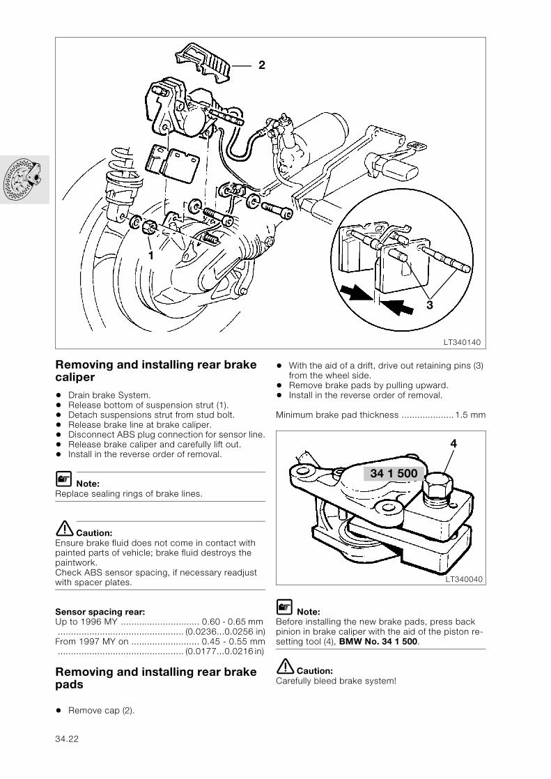
Removing and installing rear brake caliper
• Drain brake System.• Release bottom of suspension strut (1).• Detach suspensions strut from stud bolt.• Release brake line at brake caliper.• Disconnect ABS plug connection for sensor line.• Release brake caliper and carefully lift out.• Install in the reverse order of removal.
L Note:Replace sealing rings of brake lines.
e Caution:Ensure brake fluid does not come in contact with painted parts of vehicle; brake fluid destroys the paintwork.Check ABS sensor spacing, if necessary readjust with spacer plates.
Sensor spacing rear:Up to 1996 MY .............................. 0.60 - 0.65 mm ................................................ (0.0236...0.0256 in)From 1997 MY on .......................... 0.45 - 0.55 mm................................................ (0.0177...0.0216 in)
Removing and installing rear brake pads
• Remove cap (2).
• With the aid of a drift, drive out retaining pins (3) from the wheel side.
• Remove brake pads by pulling upward.• Install in the reverse order of removal.
Minimum brake pad thickness ....................1.5 mm
L Note:Before installing the new brake pads, press back pinion in brake caliper with the aid of the piston re-setting tool (4), BMW No. 34 1 500.
e Caution:Carefully bleed brake system!
LT340140
1
3
2
34 1 500
LT340040
4
34.22
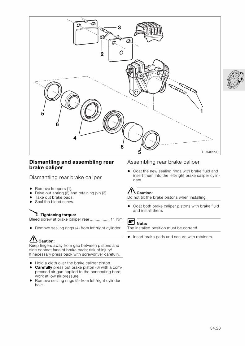
Dismantling and assembling rear brake caliper
Dismantling rear brake caliper
• Remove keepers (1).• Drive out spring (2) and retaining pin (3). • Take out brake pads.• Seal the bleed screw.
X Tightening torque:Bleed screw at brake caliper rear ................. 11 Nm
• Remove sealing rings (4) from left/right cylinder.
e Caution:Keep fingers away from gap between pistons and side contact face of brake pads; risk of injury! If necessary press back with screwdriver carefully.
• Hold a cloth over the brake caliper piston.• Carefully press out brake piston (6) with a com-
pressed air gun applied to the connecting bore; work at low air pressure.
• Remove sealing rings (5) from left/right cylinder hole.
Assembling rear brake caliper
• Coat the new sealing rings with brake fluid and insert them into the left/right brake caliper cylin-ders.
e Caution:Do not tilt the brake pistons when installing.
• Coat both brake caliper pistons with brake fluid and install them.
L Note:The installed position must be correct!
• Insert brake pads and secure with retainers.
LT340290
2
1
3
4
6
6
5
5
34.23
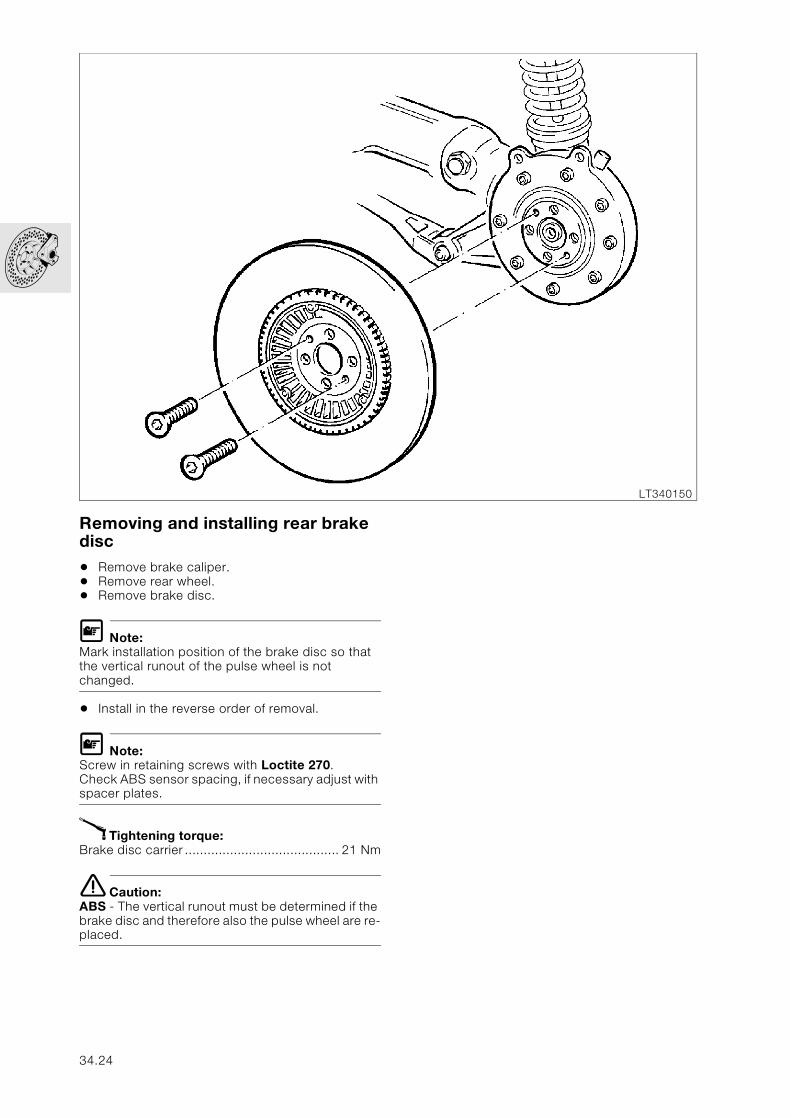
Removing and installing rear brake disc
• Remove brake caliper.• Remove rear wheel.• Remove brake disc.
L Note:Mark installation position of the brake disc so that the vertical runout of the pulse wheel is not changed.
• Install in the reverse order of removal.
L Note:Screw in retaining screws with Loctite 270. Check ABS sensor spacing, if necessary adjust with spacer plates.
X Tightening torque:Brake disc carrier ......................................... 21 Nm
e Caution:ABS - The vertical runout must be determined if the brake disc and therefore also the pulse wheel are re-placed.
LT340150
34.24
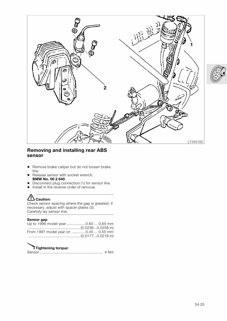
Removing and installing rear ABS sensor
• Remove brake caliper but do not loosen brake line.
• Release sensor with socket wrench, BMW No. 00 2 640.
• Disconnect plug connection (1) for sensor line.• Install in the reverse order of removal.
e Caution:Check sensor spacing where the gap is greatest; if necessary, adjust with spacer plates (3).Carefully lay sensor line.
Sensor gap Up to 1996 model year..................0.60 ... 0,65 mm................................................ (0.0236...0.0256 in)From 1997 model year on ............0.45 ... 0.55 mm................................................ (0.0177...0.0216 in)
X Tightening torque:Sensor .......................................................... 4 Nm
LT340160
2
1
34.25
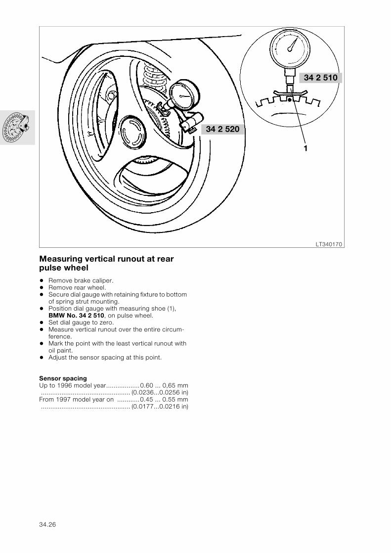
Measuring vertical runout at rear pulse wheel
• Remove brake caliper.• Remove rear wheel.• Secure dial gauge with retaining fixture to bottom
of spring strut mounting. • Position dial gauge with measuring shoe (1),
BMW No. 34 2 510, on pulse wheel.• Set dial gauge to zero.• Measure vertical runout over the entire circum-
ference.• Mark the point with the least vertical runout with
oil paint.• Adjust the sensor spacing at this point.
Sensor spacingUp to 1996 model year..................0.60 ... 0,65 mm................................................ (0.0236...0.0256 in)From 1997 model year on ............0.45 ... 0.55 mm................................................ (0.0177...0.0216 in)
LT340170
1
34 2 520
34 2 510
34.26
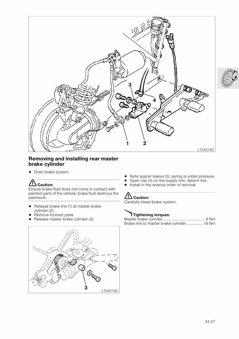
Removing and installing rear master brake cylinder
• Drain brake system.
e Caution:Ensure brake fluid does not come in contact with painted parts of the vehicle; brake fluid destroys the paintwork.
• Release brake line (1) at master brake cylinder (2).
• Remove footrest plate.• Release master brake cylinder (2).
• Note spacer sleeve (3); spring is under pressure.• Open clip (4) on the supply line, detach line.• Install in the reverse order of removal.
e Caution:Carefully bleed brake system.
X Tightening torques:Master brake cylinder..................................... 9 NmBrake line to master brake cylinder .............. 18 Nm
LT340180
1 2
3
4
LT3401903
34.27
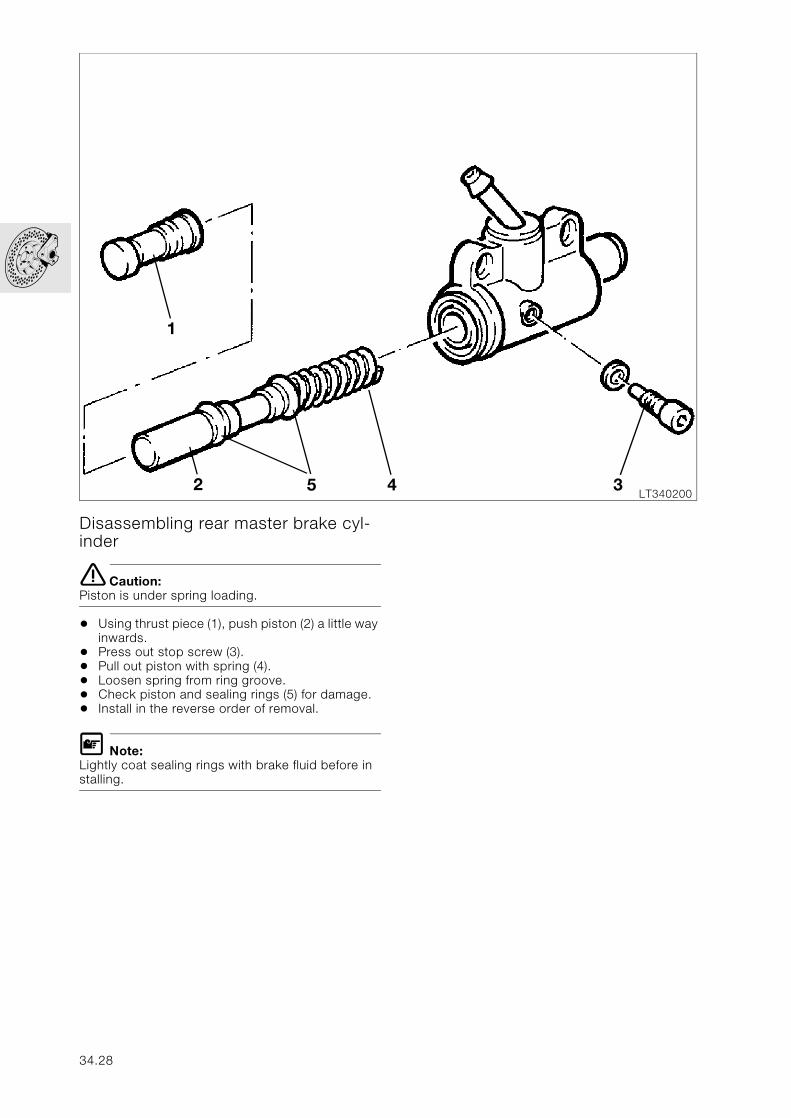
Disassembling rear master brake cyl-inder
e Caution:Piston is under spring loading.
• Using thrust piece (1), push piston (2) a little way inwards.
• Press out stop screw (3).• Pull out piston with spring (4).• Loosen spring from ring groove.• Check piston and sealing rings (5) for damage.• Install in the reverse order of removal.
L Note:Lightly coat sealing rings with brake fluid before in stalling.
LT340200
1
452 3
34.28
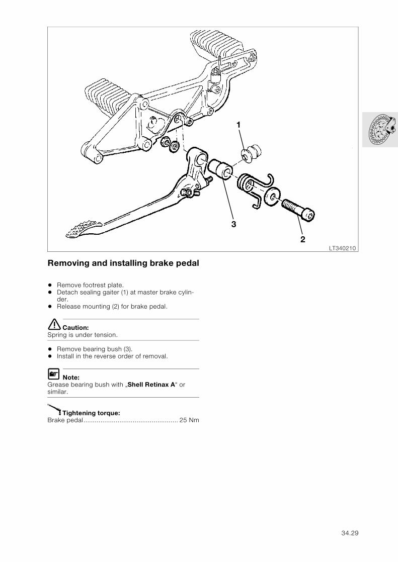
Removing and installing brake pedal
• Remove footrest plate.• Detach sealing gaiter (1) at master brake cylin-
der.• Release mounting (2) for brake pedal.
e Caution:Spring is under tension.
• Remove bearing bush (3).• Install in the reverse order of removal.
L Note:Grease bearing bush with „Shell Retinax A“ or similar.
X Tightening torque:Brake pedal.................................................. 25 Nm
LT340210
3
2
1
34.29
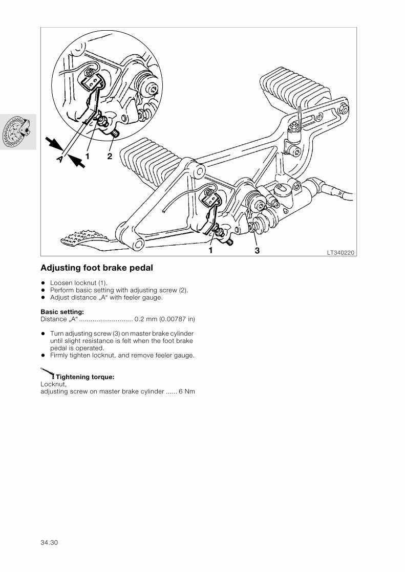
Adjusting foot brake pedal
• Loosen locknut (1).• Perform basic setting with adjusting screw (2).• Adjust distance „A“ with feeler gauge.
Basic setting:Distance „A“ ............................ 0.2 mm (0.00787 in)
• Turn adjusting screw (3) on master brake cylinder until slight resistance is felt when the foot brake pedal is operated.
• Firmly tighten locknut, and remove feeler gauge.
X Tightening torque:Locknut, adjusting screw on master brake cylinder ...... 6 Nm
LT34022031
21A
34.30
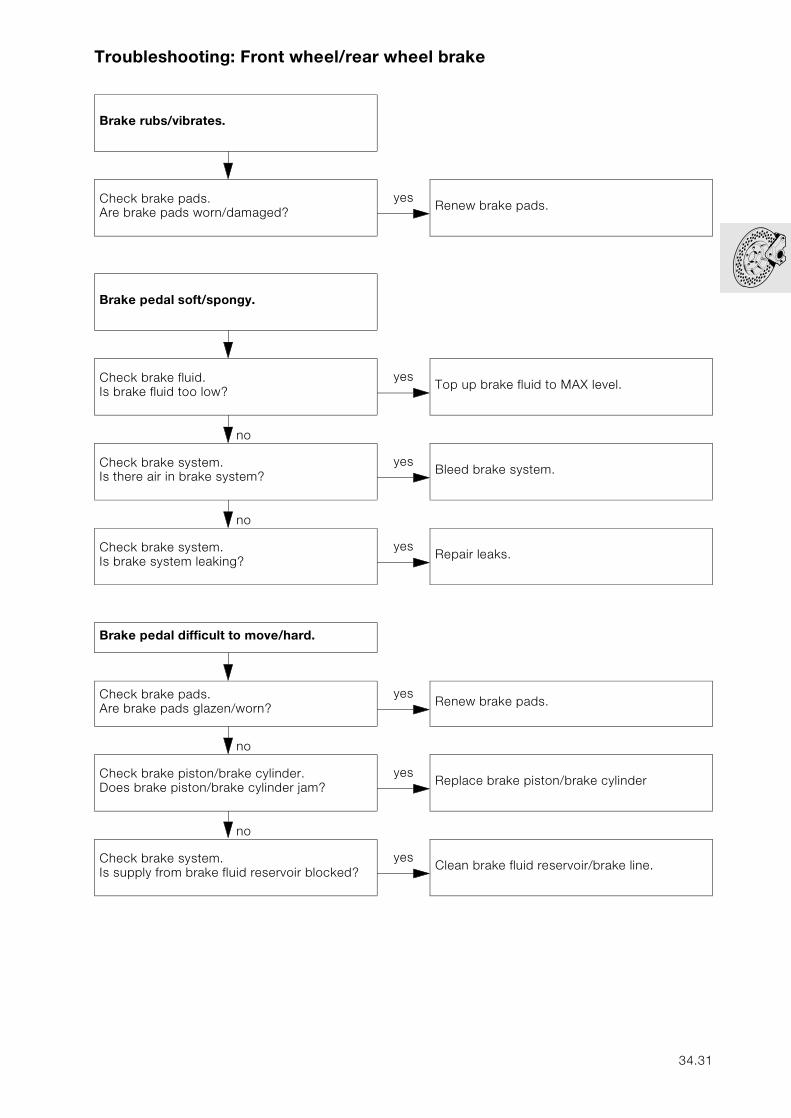
Troubleshooting: Front wheel/rear wheel brake
Brake rubs/vibrates.
no
Check brake pads.Are brake pads worn/damaged?
yesRenew brake pads.
Brake pedal soft/spongy.
no
Check brake fluid.Is brake fluid too low?
yesTop up brake fluid to MAX level.
no
Check brake system.Is there air in brake system?
yesBleed brake system.
no
Check brake system.Is brake system leaking?
yesRepair leaks.
Brake pedal difficult to move/hard.
no
Check brake pads.Are brake pads glazen/worn?
yesRenew brake pads.
no
Check brake piston/brake cylinder.Does brake piston/brake cylinder jam?
yesReplace brake piston/brake cylinder
no
Check brake system.Is supply from brake fluid reservoir blocked?
yesClean brake fluid reservoir/brake line.
34.31
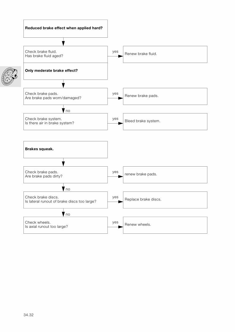
Reduced brake effect when applied hard?
no
Check brake fluid.Has brake fluid aged?
yesRenew brake fluid.
Only mederate brake effect?
no
Check brake pads.Are brake pads worn/damaged?
yesRenew brake pads.
no
Check brake system.Is there air in brake system?
yesBleed brake system.
Brakes squeak.
no
Check brake pads.Are brake pads dirty?
yesrenew brake pads.
no
Check brake discs.Is lateral runout of brake discs too large?
yesReplace brake discs.
no
Check wheels.Is axial runout too large?
yesRenew wheels.
34.32
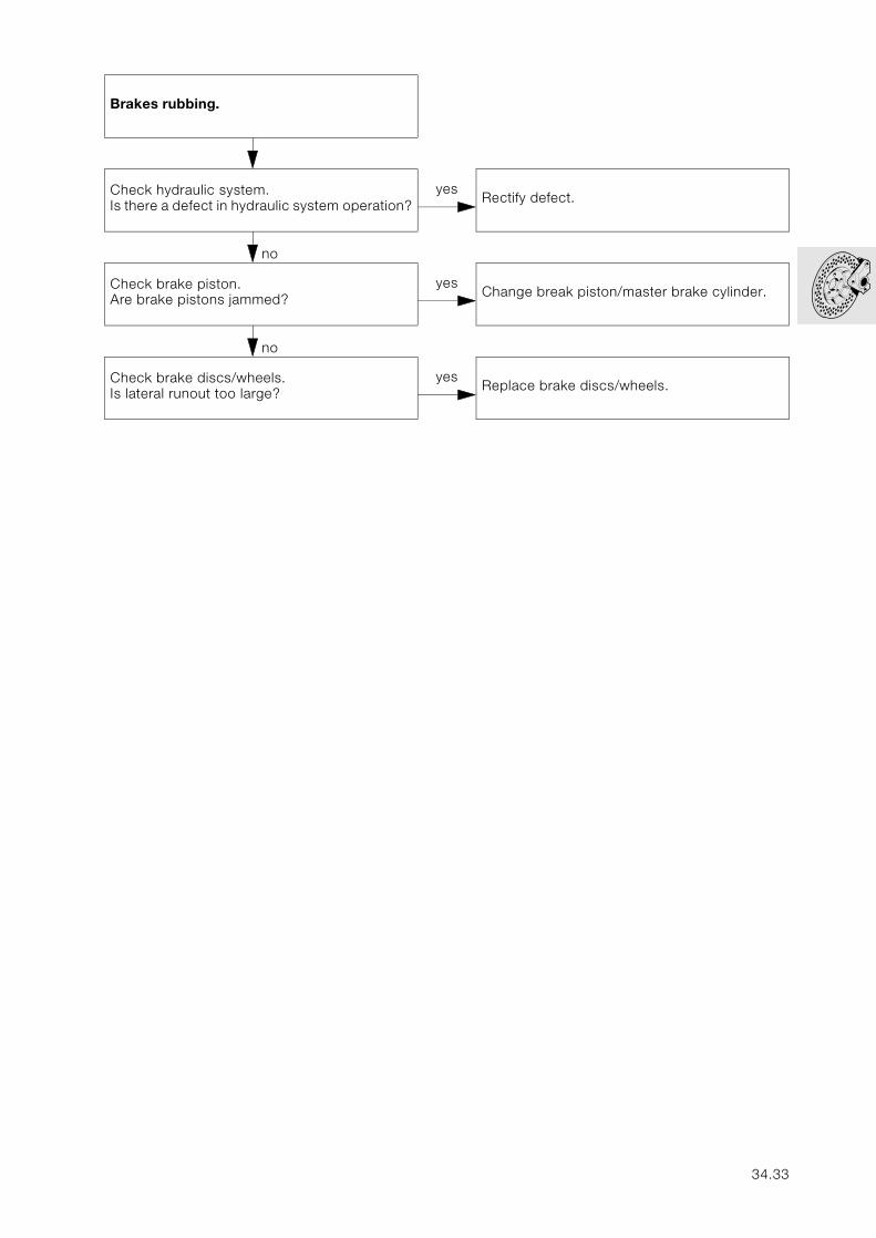
Brakes rubbing.
no
Check hydraulic system.Is there a defect in hydraulic system operation?
yesRectify defect.
no
Check brake piston.Are brake pistons jammed?
yesChange break piston/master brake cylinder.
no
Check brake discs/wheels.Is lateral runout too large?
yesReplace brake discs/wheels.
34.33

34.34
36
Contents Page
36 Wheels and tyres
Technical Data ............................................................................................................................... 3
Removing and installing front wheel .................................................................................5
Removing and instaling wheel bearings ...............................................................................6Removing left bearing .........................................................................................................................6Removing right bearing .......................................................................................................................6Installing left and right bearings ...........................................................................................................6
Removing and installing rear wheel ...................................................................................7
Removing rear wheel .....................................................................................................................7
Installing rear wheel .......................................................................................................................7
Static balancing of front and rear wheels .......................................................................8
Static balancing of front wheel ..................................................................................................8
Static balancing of rear wheel ...................................................................................................8
Checking wheel for runout ......................................................................................................9
Checking front wheel for runout ...............................................................................................9
Checking rear wheel for runout ................................................................................................9
36.1

36.2
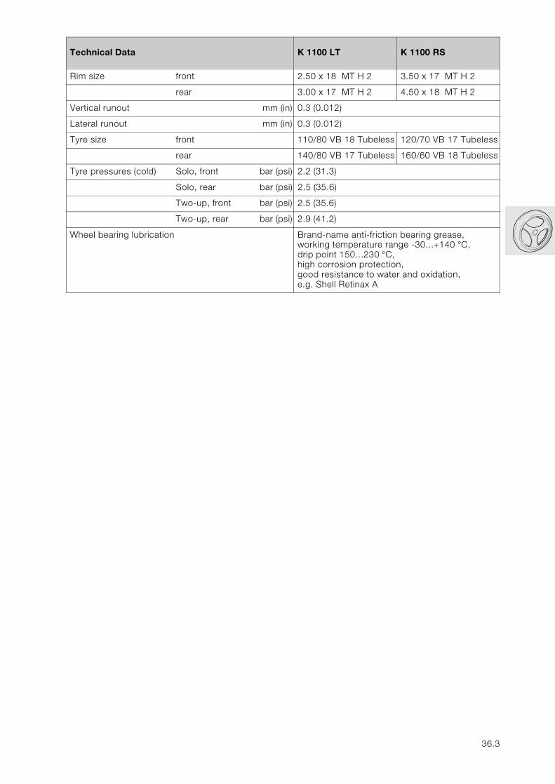
36
Technical Data K 1100 LT K 1100 RS
Rim size front 2.50 x 18 MT H 2 3.50 x 17 MT H 2
rear 3.00 x 17 MT H 2 4.50 x 18 MT H 2
Vertical runout mm (in) 0.3 (0.012)
Lateral runout mm (in) 0.3 (0.012)
Tyre size front 110/80 VB 18 Tubeless 120/70 VB 17 Tubeless
rear 140/80 VB 17 Tubeless 160/60 VB 18 Tubeless
Tyre pressures (cold) Solo, front bar (psi) 2.2 (31.3)
Solo, rear bar (psi) 2.5 (35.6)
Two-up, front bar (psi) 2.5 (35.6)
Two-up, rear bar (psi) 2.9 (41.2)
Wheel bearing lubrication Brand-name anti-friction bearing grease,working temperature range -30…+140 °C,drip point 150…230 °C,high corrosion protection,good resistance to water and oxidation,e.g. Shell Retinax A
36.3

36.4
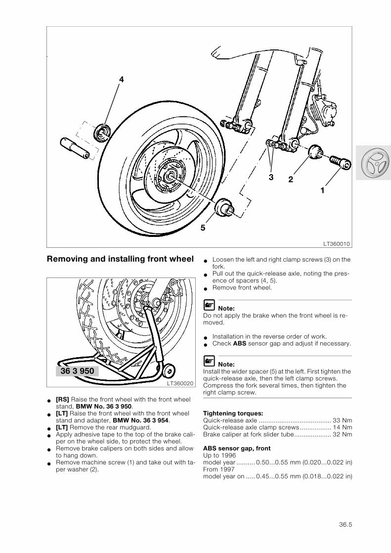
1
3 2
LT360010
Removing and installing front wheel
• [RS] Raise the front wheel with the front wheel stand, BMW No. 36 3 950.
• [LT] Raise the front wheel with the front wheel stand and adapter, BMW No. 36 3 954.
• [LT] Remove the rear mudguard.
• Apply adhesive tape to the top of the brake cali-per on the wheel side, to protect the wheel.
• Remove brake calipers on both sides and allow to hang down.
• Remove machine screw (1) and take out with ta-per washer (2).
4
5
LT360020
36 3 950
• Loosen the left and right clamp screws (3) on the fork.
• Pull out the quick-release axle, noting the pres-ence of spacers (4, 5).
• Remove front wheel.
L Note:Do not apply the brake when the front wheel is re-moved.
• Installation in the reverse order of work.
• Check ABS sensor gap and adjust if necessary.
L Note:Install the wider spacer (5) at the left. First tighten the quick-release axle, then the left clamp screws. Compress the fork several times, then tighten the right clamp screw.
Tightening torques:Quick-release axle ....................................... 33 NmQuick-release axle clamp screws................. 14 NmBrake caliper at fork slider tube.................... 32 Nm
ABS sensor gap, frontUp to 1996 model year .......... 0.50…0.55 mm (0.020…0.022 in)From 1997 model year on ..... 0.45…0.55 mm (0.018…0.022 in)
36.5
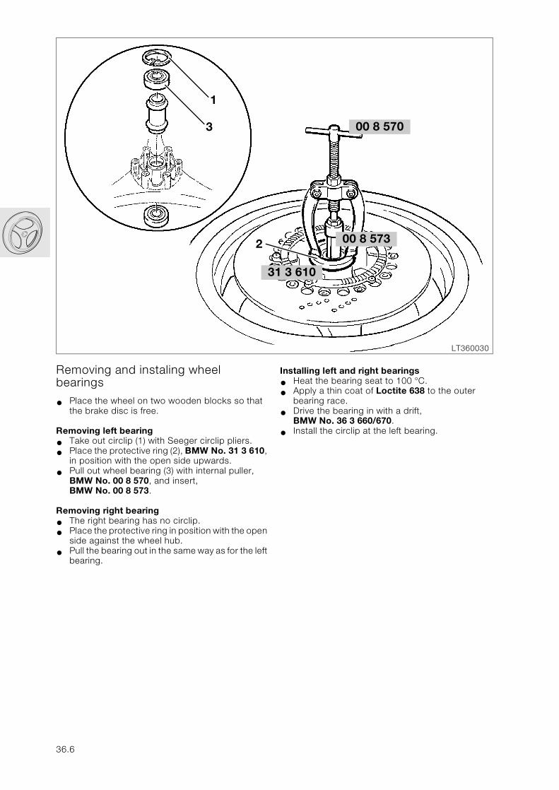
LT360030
00 8 573
00 8 570
3 610
Removing and instaling wheel bearings
• Place the wheel on two wooden blocks so that the brake disc is free.
Removing left bearing
• Take out circlip (1) with Seeger circlip pliers.
• Place the protective ring (2), BMW No. 31 3 610, in position with the open side upwards.
• Pull out wheel bearing (3) with internal puller, BMW No. 00 8 570, and insert, BMW No. 00 8 573.
Removing right bearing
• The right bearing has no circlip.
• Place the protective ring in position with the open side against the wheel hub.
• Pull the bearing out in the same way as for the left bearing.
31
2
3
1
36.6
Installing left and right bearings
• Heat the bearing seat to 100 °C.
• Apply a thin coat of Loctite 638 to the outer bearing race.
• Drive the bearing in with a drift, BMW No. 36 3 660/670.
• Install the circlip at the left bearing.
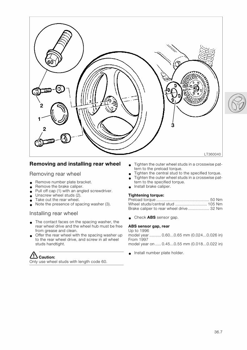
LT360040
3
Removing and installing rear wheel
Removing rear wheel
• Remove number plate bracket.
• Remove the brake caliper.
• Pull off cap (1) with an angled screwdriver.
• Unscrew wheel studs (2).
• Take out the rear wheel.
• Note the presence of spacing washer (3).
Installing rear wheel
• The contact faces on the spacing washer, the rear wheel drive and the wheel hub must be free from grease and clean.
• Offer the rear wheel with the spacing washer up to the rear wheel drive, and screw in all wheel studs handtight.
e Caution:Only use wheel studs with length code 60.
1
2
2
60
• Tighten the outer wheel studs in a crosswise pat-tern to the preload torque.
• Tighten the central stud to the specified torque.
• Tighten the outer wheel studs in a crosswise pat-tern to the specified torque.
• Install brake caliper.
Tightening torque:Preload torque ............................................. 50 NmWheel studs/central stud ........................... 105 NmBrake caliper to rear wheel drive .................. 32 Nm
• Check ABS sensor gap.
ABS sensor gap, rearUp to 1996model year .......... 0.60…0.65 mm (0.024…0.026 in)From 1997 model year on ..... 0.45…0.55 mm (0.018…0.022 in)
• Install number plate holder.
36.7
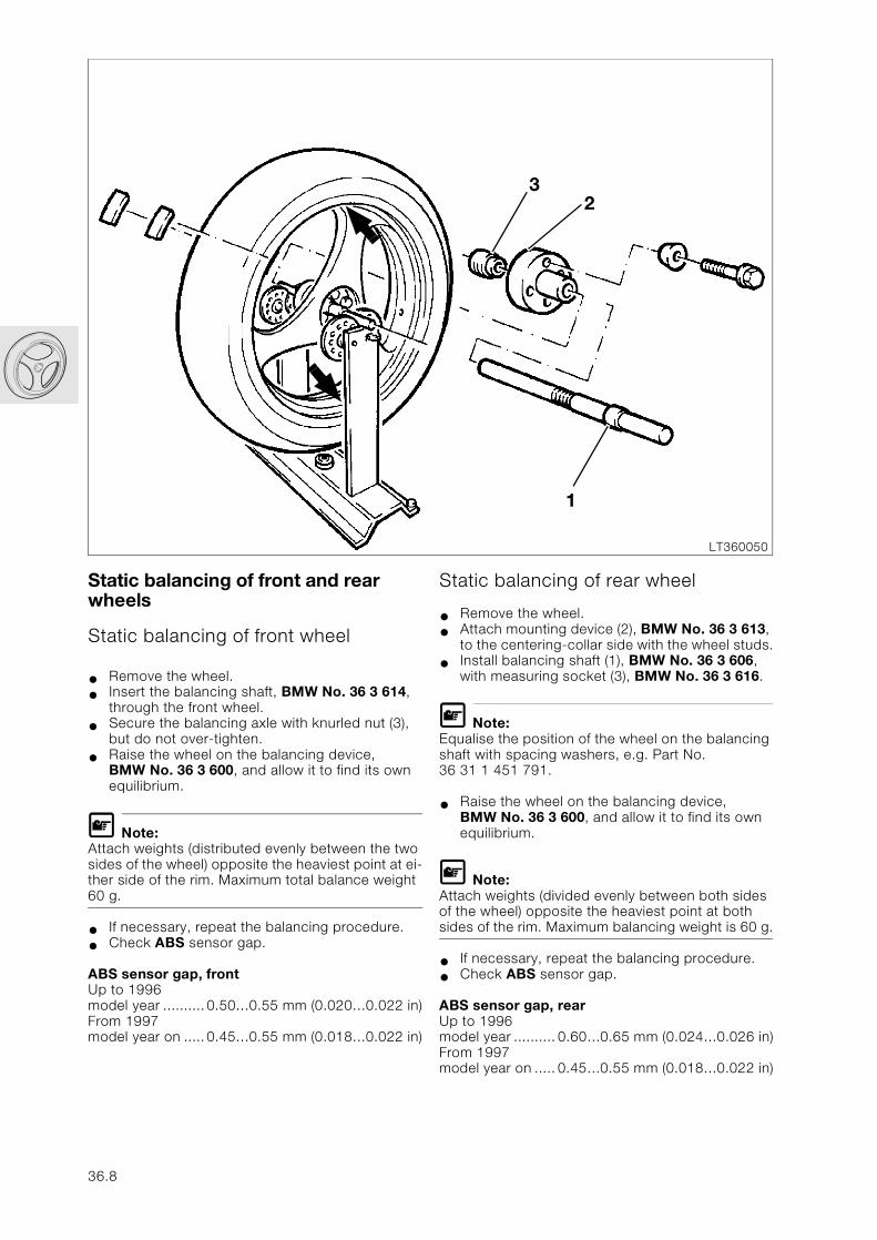
LT360050
32
1
Static balancing of front and rear wheels
Static balancing of front wheel
• Remove the wheel.
• Insert the balancing shaft, BMW No. 36 3 614, through the front wheel.
• Secure the balancing axle with knurled nut (3), but do not over-tighten.
• Raise the wheel on the balancing device, BMW No. 36 3 600, and allow it to find its own equilibrium.
L Note:Attach weights (distributed evenly between the two sides of the wheel) opposite the heaviest point at ei-ther side of the rim. Maximum total balance weight 60 g.
• If necessary, repeat the balancing procedure.
• Check ABS sensor gap.
ABS sensor gap, frontUp to 1996model year ..........0.50…0.55 mm (0.020…0.022 in)From 1997 model year on .....0.45…0.55 mm (0.018…0.022 in)
36.8
Static balancing of rear wheel
• Remove the wheel.
• Attach mounting device (2), BMW No. 36 3 613, to the centering-collar side with the wheel studs.
• Install balancing shaft (1), BMW No. 36 3 606, with measuring socket (3), BMW No. 36 3 616.
L Note:Equalise the position of the wheel on the balancing shaft with spacing washers, e.g. Part No. 36 31 1 451 791.
• Raise the wheel on the balancing device, BMW No. 36 3 600, and allow it to find its own equilibrium.
L Note:Attach weights (divided evenly between both sides of the wheel) opposite the heaviest point at both sides of the rim. Maximum balancing weight is 60 g.
• If necessary, repeat the balancing procedure.
• Check ABS sensor gap.
ABS sensor gap, rearUp to 1996model year .......... 0.60…0.65 mm (0.024…0.026 in)From 1997 model year on ..... 0.45…0.55 mm (0.018…0.022 in)
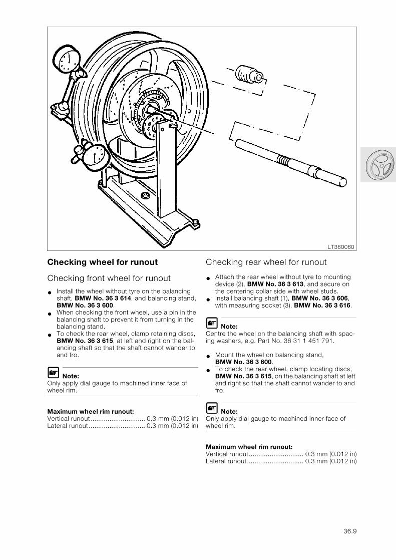
Checking wheel for runout
Checking front wheel for runout
• Install the wheel without tyre on the balancing shaft, BMW No. 36 3 614, and balancing stand, BMW No. 36 3 600.
• When checking the front wheel, use a pin in the balancing shaft to prevent it from turning in the balancing stand.
• To check the rear wheel, clamp retaining discs, BMW No. 36 3 615, at left and right on the bal-ancing shaft so that the shaft cannot wander to and fro.
L Note:Only apply dial gauge to machined inner face of wheel rim.
Maximum wheel rim runout:Vertical runout............................. 0.3 mm (0.012 in)Lateral runout.............................. 0.3 mm (0.012 in)
Checking rear wheel for runout
• Attach the rear wheel without tyre to mounting device (2), BMW No. 36 3 613, and secure on the centering collar side with wheel studs.
• Install balancing shaft (1), BMW No. 36 3 606, with measuring socket (3), BMW No. 36 3 616.
L Note:Centre the wheel on the balancing shaft with spac-ing washers, e.g. Part No. 36 31 1 451 791.
• Mount the wheel on balancing stand, BMW No. 36 3 600.
• To check the rear wheel, clamp locating discs, BMW No. 36 3 615, on the balancing shaft at left and right so that the shaft cannot wander to and fro.
L Note:Only apply dial gauge to machined inner face of wheel rim.
Maximum wheel rim runout:Vertical runout............................. 0.3 mm (0.012 in)Lateral runout.............................. 0.3 mm (0.012 in)
LT360060
36.9

36.10
46
Contents Page
46 Frame
Technical Data ............................................................................................................................... 3
Removing and installing front mudguard ........................................................................5
Removing and installing rear section ................................................................................6
Removing and installing rear mudguard .........................................................................7
Removing and installing fairing [LT] ..................................................................................8
Removing side sections of fairing ............................................................................................8
Removing radiator cowling .........................................................................................................8
Removing and installing windshield ........................................................................................9
Removing and installing windshield complete with motor ............................................9
Disassembling and assembling adjustable windshield ................................................10Removing and installing actuator motor ............................................................................................10Removing plate .................................................................................................................................10Removing lever .................................................................................................................................11Removing guide bush in lever ...........................................................................................................11Removing sliding piece .....................................................................................................................11
Removing and installing upper section of fairing ............................................................12
Removing and installing fairing [RS] ...............................................................................13
Removing and installing lower section of fairing .............................................................13
Removing and installing side section of fairing ...............................................................13
Removing and installing radiator cowling ..........................................................................13
Removing and installing upper section of fairing ............................................................14
Removing and installing windshield, spoiler and headlamp ......................................14
Removing and installing fairing support bracket .............................................................15Arrangement of cable clips [LT] .........................................................................................................15Arrangement of cable clips [RS] ........................................................................................................15
Checking running gear ............................................................................................................16
Measuring track offset ................................................................................................................16
46.1
Contents Page
Checking frame with gauge ......................................................................................................18
Removing and installing frame ...........................................................................................20
Removing frame .............................................................................................................................20
Disassembling and assembling frame .................................................................................20Removing outer bearing race in steering head ..................................................................................20Installing outer bearing race in steering head ....................................................................................20Removing and installing seat lock .....................................................................................................21Removing and installing handle .........................................................................................................21
Installing frame ...............................................................................................................................22
Removing and installing main centre stand ................................................................23Line arrangement for side stand ........................................................................................................23
Disassembling and assembling side stand .......................................................................24Disassembling side stand ..................................................................................................................24Assembling side stand ......................................................................................................................25
Disassembling and assembling main centre stand .......................................................26
Checking switching function of side stand .................................................................27
46.2
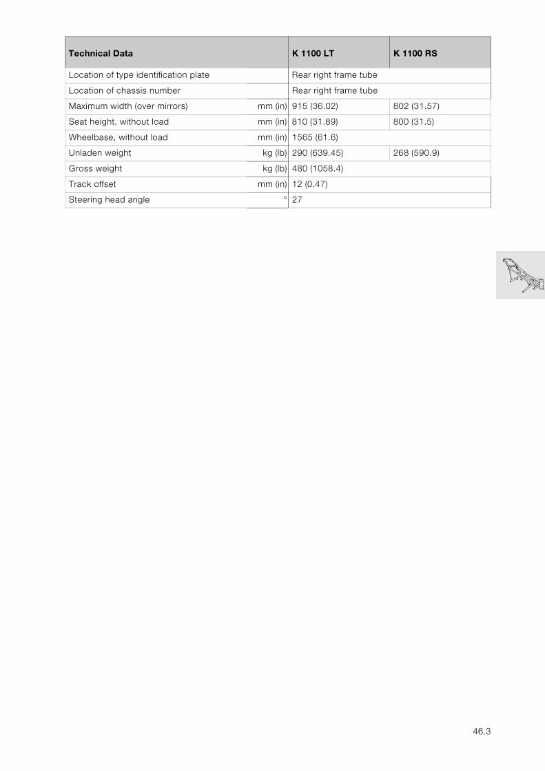
46
Technical Data K 1100 LT K 1100 RS
Location of type identification plate Rear right frame tube
Location of chassis number Rear right frame tube
Maximum width (over mirrors) mm (in) 915 (36.02) 802 (31.57)
Seat height, without load mm (in) 810 (31.89) 800 (31.5)
Wheelbase, without load mm (in) 1565 (61.6)
Unladen weight kg (lb) 290 (639.45) 268 (590.9)
Gross weight kg (lb) 480 (1058.4)
Track offset mm (in) 12 (0.47)
Steering head angle ° 27
46.3

46.4
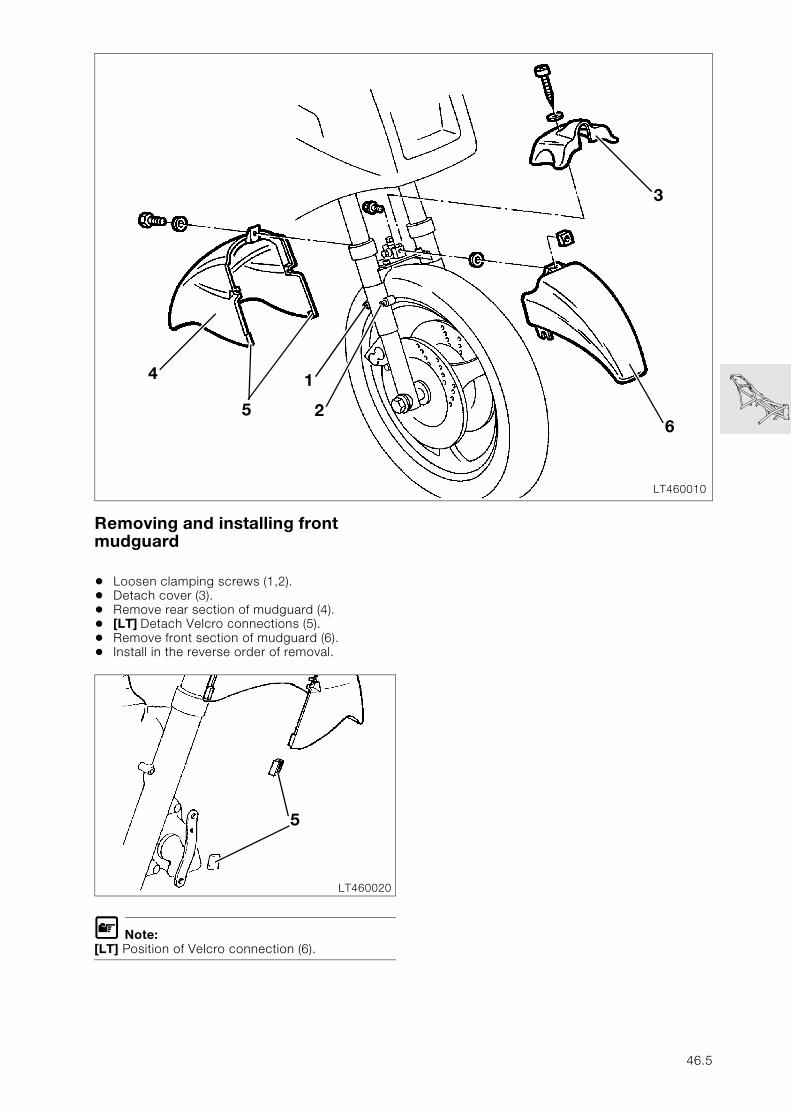
Removing and installing front mudguard
• Loosen clamping screws (1,2).• Detach cover (3).• Remove rear section of mudguard (4).• [LT] Detach Velcro connections (5).• Remove front section of mudguard (6).• Install in the reverse order of removal.
L Note:[LT] Position of Velcro connection (6).
LT460010
4
6
3
1
25
LT460020
5
46.5
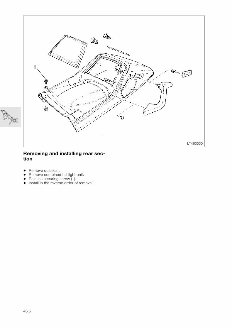
Removing and installing rear sec-tion
• Remove dualseat.• Remove combined tail light unit.• Release securing screw (1).• Install in the reverse order of removal.
LT460030
1
46.6
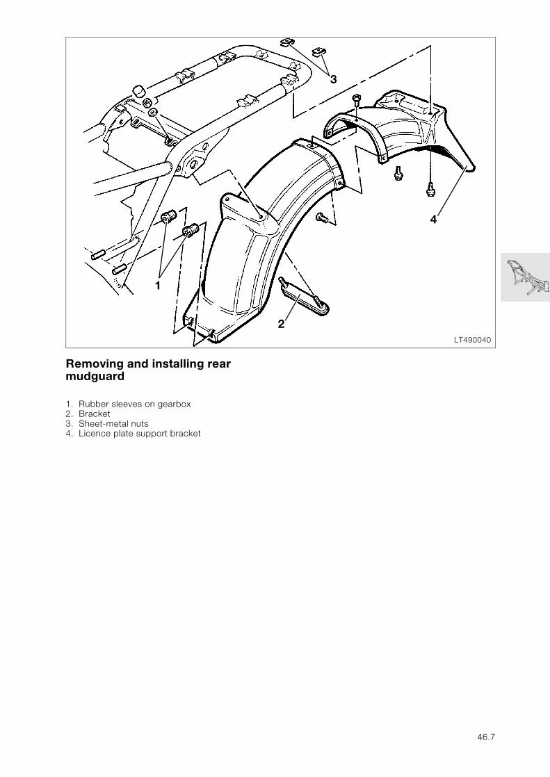
Removing and installing rear mudguard
1. Rubber sleeves on gearbox2. Bracket3. Sheet-metal nuts4. Licence plate support bracket
LT490040
3
4
2
1
46.7
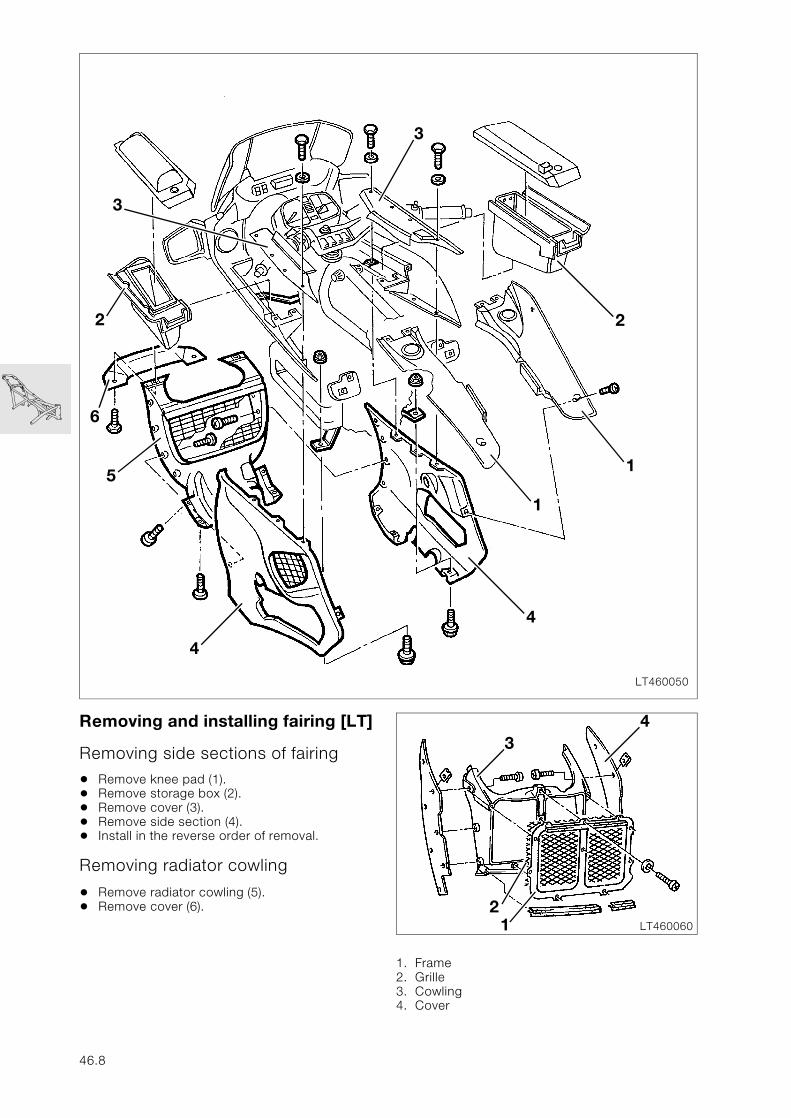
Removing and installing fairing [LT]
Removing side sections of fairing
• Remove knee pad (1).• Remove storage box (2).• Remove cover (3).• Remove side section (4).• Install in the reverse order of removal.
Removing radiator cowling
• Remove radiator cowling (5).• Remove cover (6).
1. Frame2. Grille3. Cowling4. Cover
LT460050
3
3
2
6
5
4
4
1
1
2
LT460060
2
4
1
3
46.8
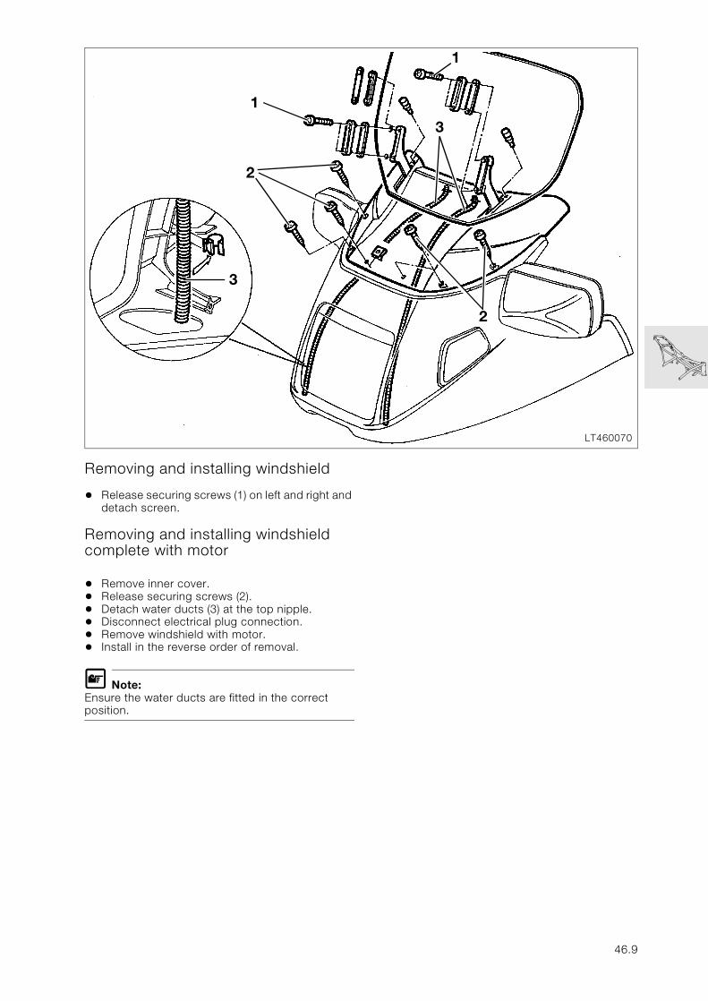
Removing and installing windshield
• Release securing screws (1) on left and right and detach screen.
Removing and installing windshield complete with motor
• Remove inner cover.• Release securing screws (2).• Detach water ducts (3) at the top nipple.• Disconnect electrical plug connection.• Remove windshield with motor.• Install in the reverse order of removal.
L Note:Ensure the water ducts are fitted in the correct position.
LT460070
2
1
3
1
2
3
46.9
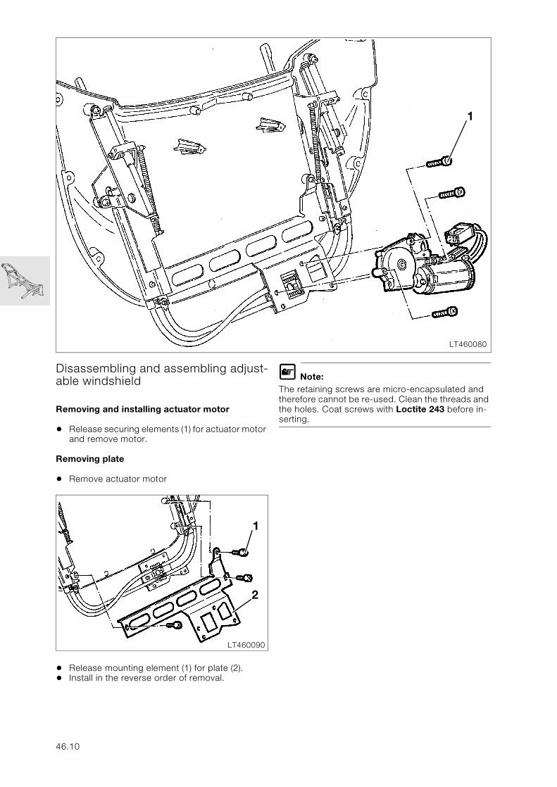
Disassembling and assembling adjust-able windshield
Removing and installing actuator motor
• Release securing elements (1) for actuator motor and remove motor.
Removing plate
• Remove actuator motor
• Release mounting element (1) for plate (2).• Install in the reverse order of removal.
L Note:The retaining screws are micro-encapsulated and therefore cannot be re-used. Clean the threads and the holes. Coat screws with Loctite 243 before in-serting.
LT460080
1
LT460090
2
1
46.10
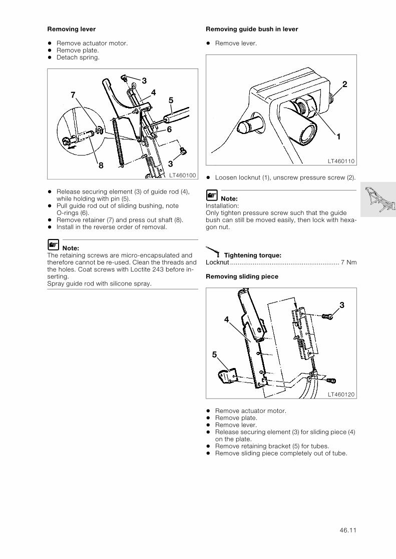
Removing lever
• Remove actuator motor.• Remove plate.• Detach spring.
• Release securing element (3) of guide rod (4), while holding with pin (5).
• Pull guide rod out of sliding bushing, note O-rings (6).
• Remove retainer (7) and press out shaft (8).• Install in the reverse order of removal.
L Note:The retaining screws are micro-encapsulated and therefore cannot be re-used. Clean the threads and the holes. Coat screws with Loctite 243 before in-serting.Spray guide rod with silicone spray.
Removing guide bush in lever
• Remove lever.
• Loosen locknut (1), unscrew pressure screw (2).
L Note:Installation:Only tighten pressure screw such that the guide bush can still be moved easily, then lock with hexa-gon nut.
X Tightening torque:Locknut .......................................................... 7 Nm
Removing sliding piece
• Remove actuator motor.• Remove plate.• Remove lever.• Release securing element (3) for sliding piece (4)
on the plate.• Remove retaining bracket (5) for tubes.• Remove sliding piece completely out of tube.
LT460100
3
4
8
3
5
6
7
LT460110
1
2
LT460120
3
5
4
46.11
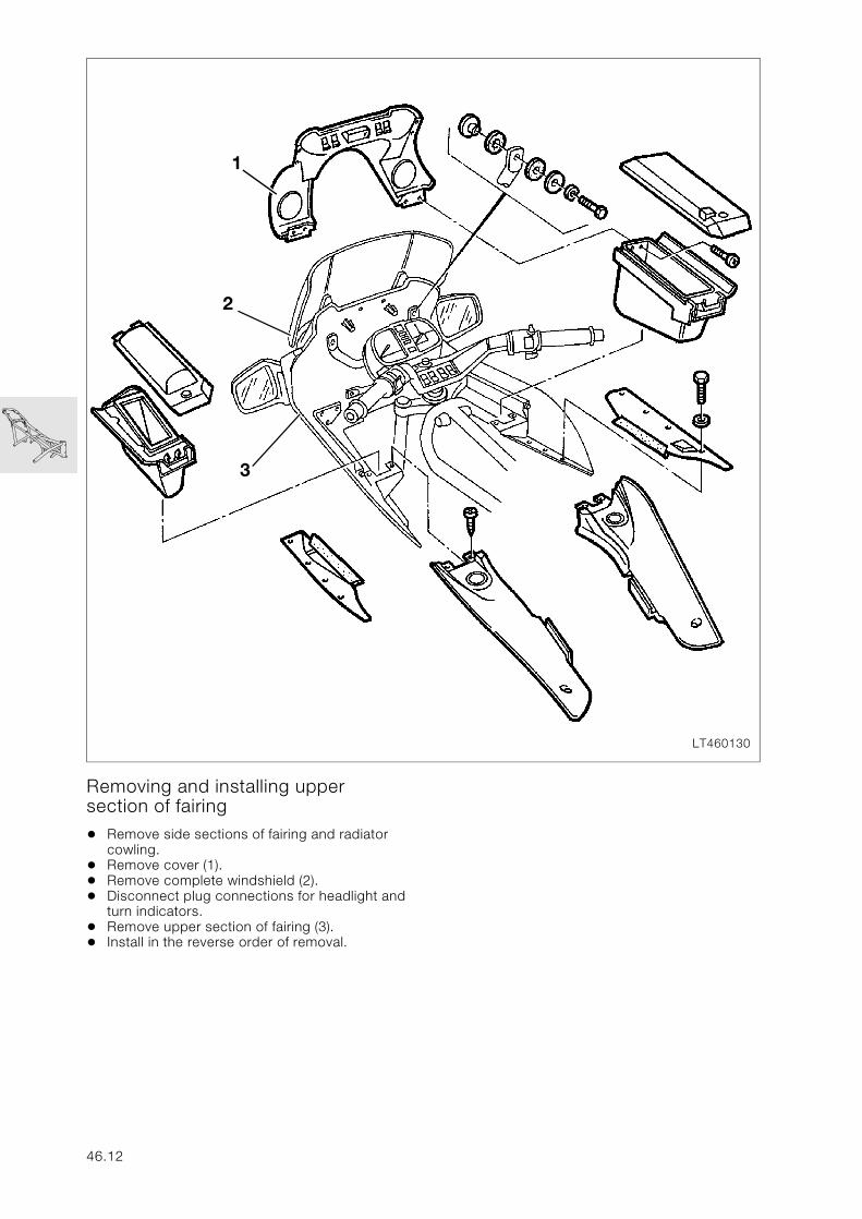
Removing and installing upper section of fairing
• Remove side sections of fairing and radiator cowling.
• Remove cover (1).• Remove complete windshield (2).• Disconnect plug connections for headlight and
turn indicators.• Remove upper section of fairing (3).• Install in the reverse order of removal.
LT460130
3
2
1
46.12
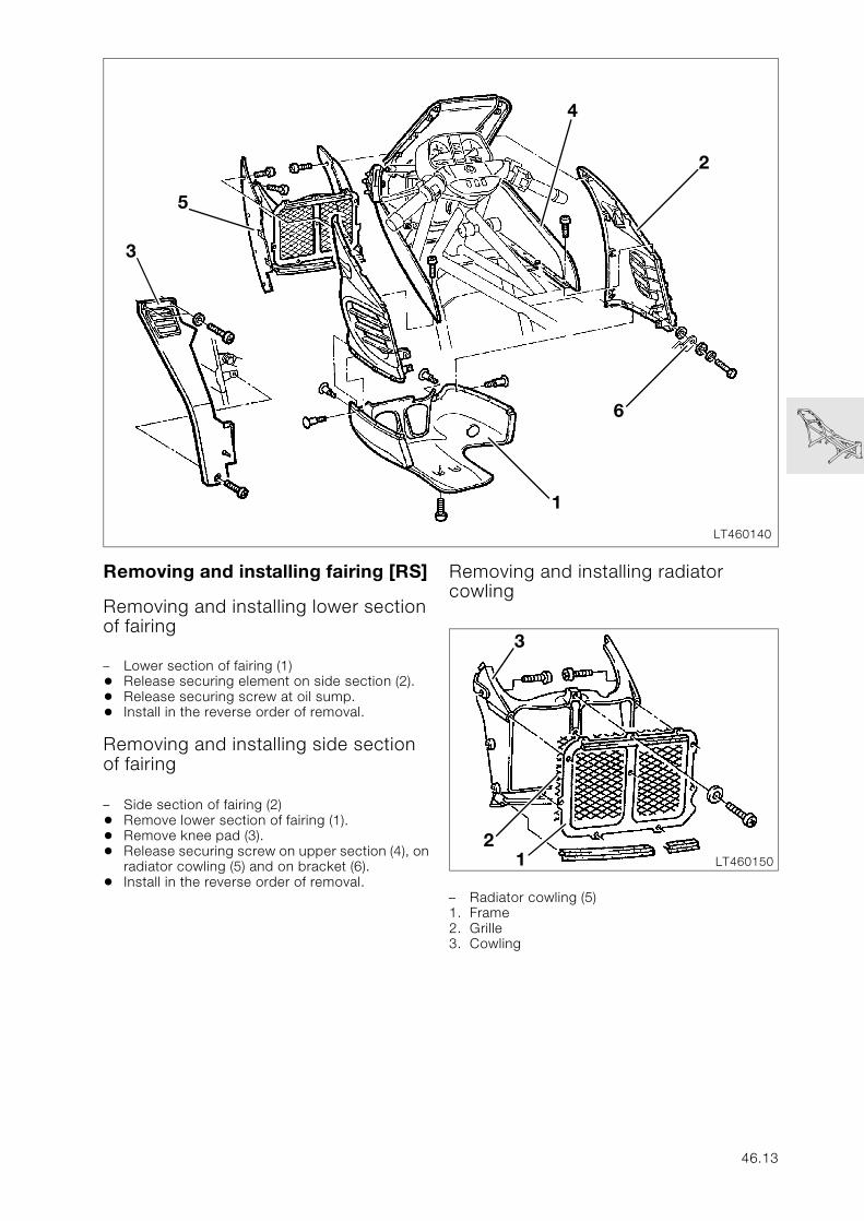
Removing and installing fairing [RS]
Removing and installing lower section of fairing
– Lower section of fairing (1)• Release securing element on side section (2).• Release securing screw at oil sump.• Install in the reverse order of removal.
Removing and installing side section of fairing
– Side section of fairing (2)• Remove lower section of fairing (1).• Remove knee pad (3).• Release securing screw on upper section (4), on
radiator cowling (5) and on bracket (6).• Install in the reverse order of removal.
Removing and installing radiator cowling
– Radiator cowling (5)1. Frame2. Grille3. Cowling
LT460140
6
4
2
5
1
3
LT460150
2
3
1
46.13
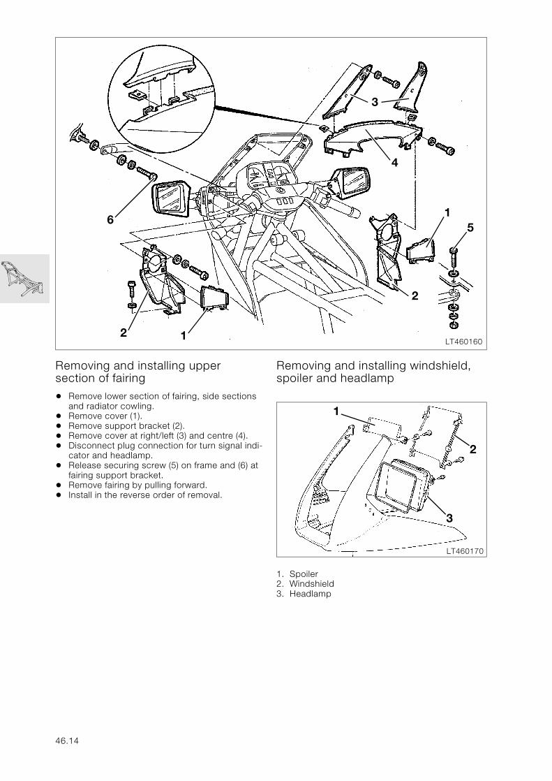
Removing and installing upper section of fairing
• Remove lower section of fairing, side sections and radiator cowling.
• Remove cover (1).• Remove support bracket (2).• Remove cover at right/left (3) and centre (4).• Disconnect plug connection for turn signal indi-
cator and headlamp.• Release securing screw (5) on frame and (6) at
fairing support bracket.• Remove fairing by pulling forward.• Install in the reverse order of removal.
Removing and installing windshield, spoiler and headlamp
1. Spoiler2. Windshield3. Headlamp
LT460160
3
61
2 1
5
2
4
LT460170
1
3
2
46.14
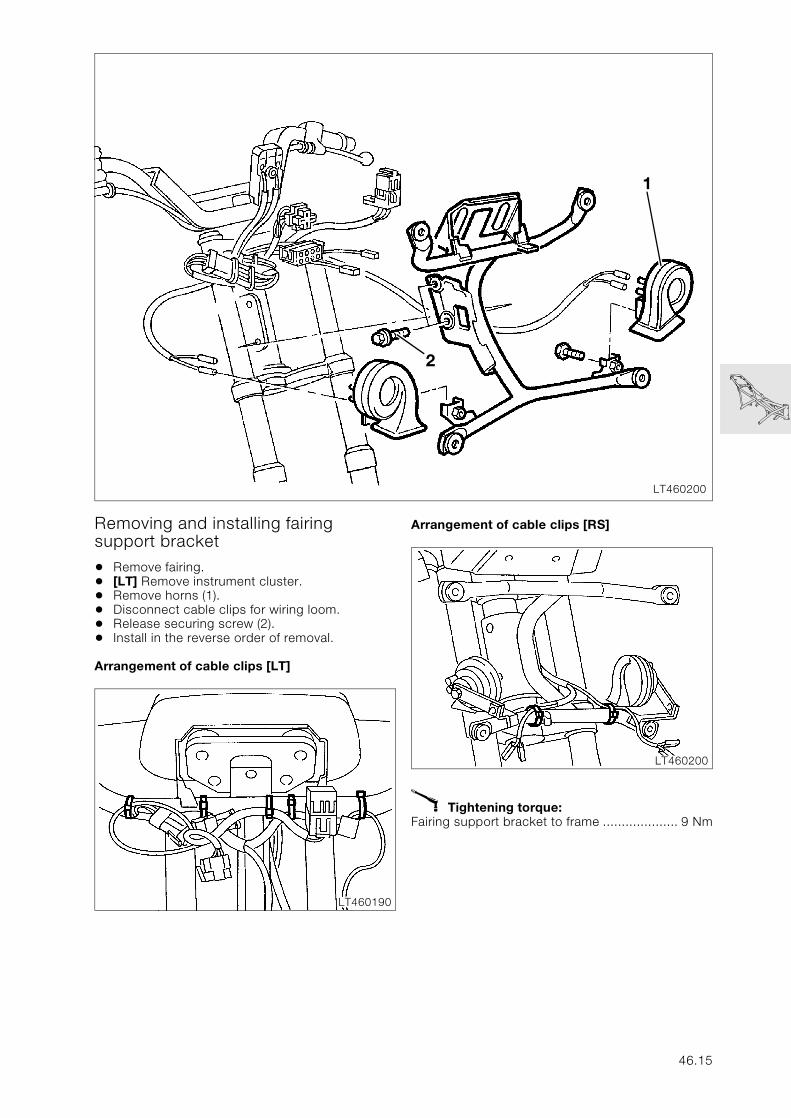
Removing and installing fairing support bracket
• Remove fairing.• [LT] Remove instrument cluster.• Remove horns (1).• Disconnect cable clips for wiring loom.• Release securing screw (2).• Install in the reverse order of removal.
Arrangement of cable clips [LT]
Arrangement of cable clips [RS]
X Tightening torque:Fairing support bracket to frame .................... 9 Nm
LT460200
1
2
LT460190
LT460200
46.15
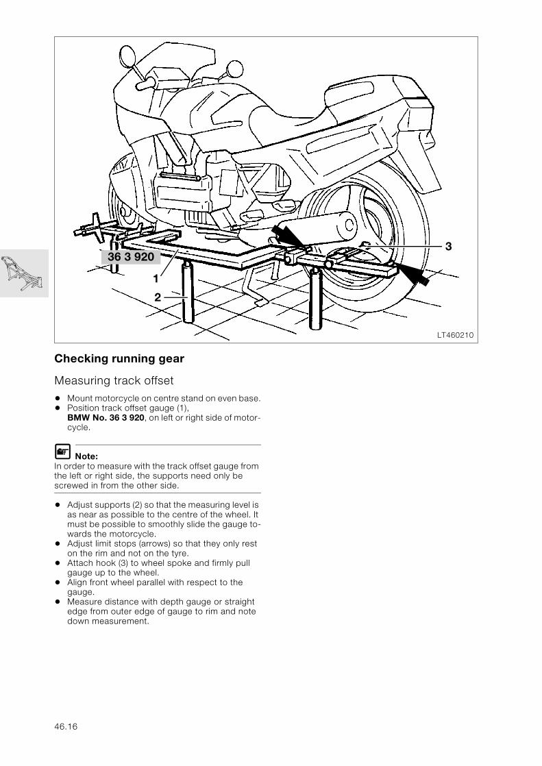
Checking running gear
Measuring track offset
• Mount motorcycle on centre stand on even base.• Position track offset gauge (1),
BMW No. 36 3 920, on left or right side of motor-cycle.
L Note:In order to measure with the track offset gauge from the left or right side, the supports need only be screwed in from the other side.
• Adjust supports (2) so that the measuring level is as near as possible to the centre of the wheel. It must be possible to smoothly slide the gauge to-wards the motorcycle.
• Adjust limit stops (arrows) so that they only rest on the rim and not on the tyre.
• Attach hook (3) to wheel spoke and firmly pull gauge up to the wheel.
• Align front wheel parallel with respect to the gauge.
• Measure distance with depth gauge or straight edge from outer edge of gauge to rim and note down measurement.
LT460210
2
336 3 920
1
46.16
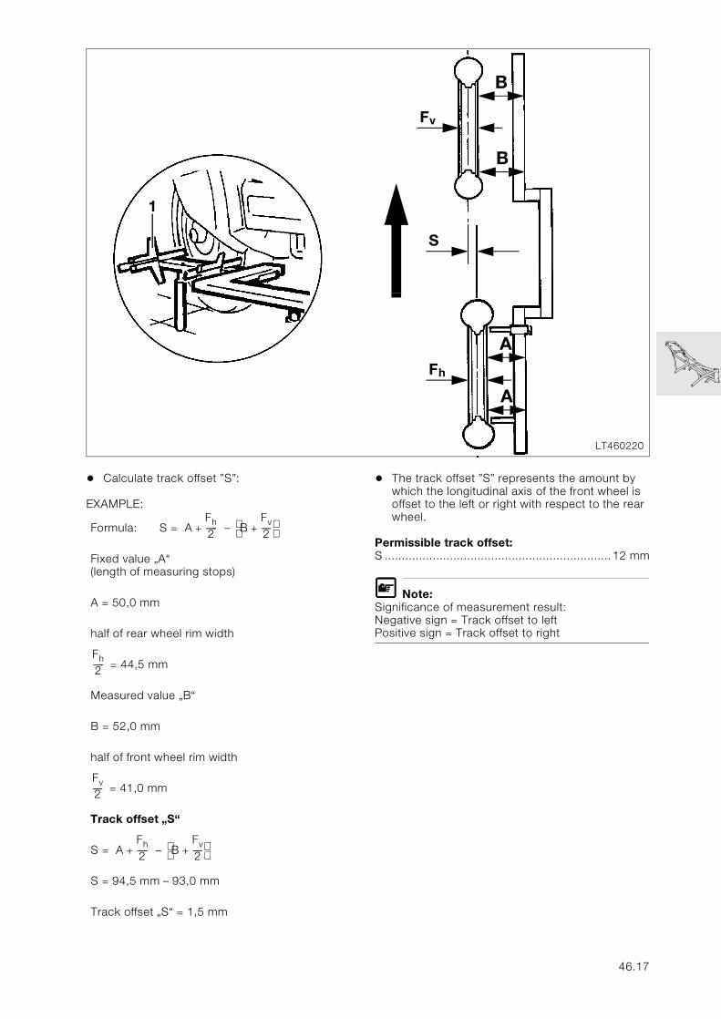
• Calculate track offset ”S”:
EXAMPLE:
• The track offset ”S” represents the amount by which the longitudinal axis of the front wheel is offset to the left or right with respect to the rear wheel.
Permissible track offset:S ..................................................................12 mm
L Note:Significance of measurement result:Negative sign = Track offset to leftPositive sign = Track offset to right
Formula: S = –
Fixed value „A“(length of measuring stops)
A = 50,0 mm
half of rear wheel rim width
= 44,5 mm
Measured value „B“
B = 52,0 mm
half of front wheel rim width
= 41,0 mm
Track offset „S“
S = –
S = 94,5 mm – 93,0 mm
Track offset „S“ = 1,5 mm
LT460220
1
B
A
B
A
S
Fv
Fh
AFh2-----+ B
Fv2----+
Fh2-----
Fv2----
AFh2-----+ B
Fv2----+
46.17
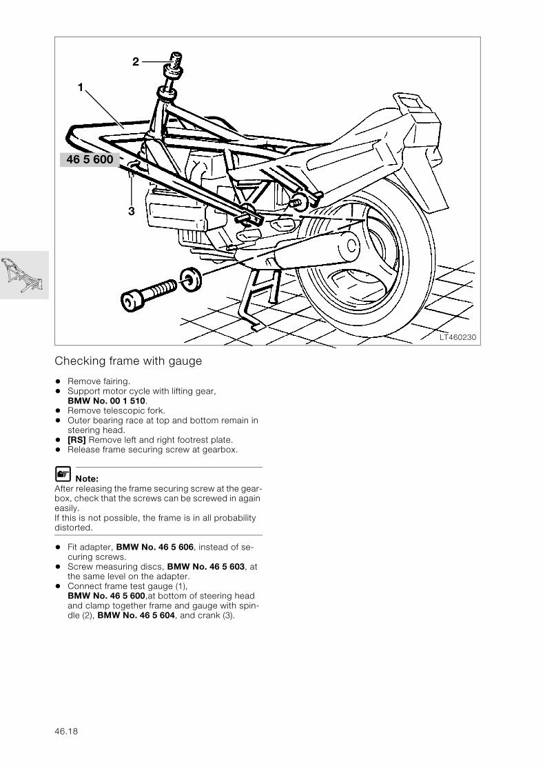
Checking frame with gauge
• Remove fairing.• Support motor cycle with lifting gear,
BMW No. 00 1 510.• Remove telescopic fork.• Outer bearing race at top and bottom remain in
steering head.• [RS] Remove left and right footrest plate.• Release frame securing screw at gearbox.
L Note:After releasing the frame securing screw at the gear-box, check that the screws can be screwed in again easily.If this is not possible, the frame is in all probability distorted.
• Fit adapter, BMW No. 46 5 606, instead of se-curing screws.
• Screw measuring discs, BMW No. 46 5 603, at the same level on the adapter.
• Connect frame test gauge (1), BMW No. 46 5 600,at bottom of steering head and clamp together frame and gauge with spin-dle (2), BMW No. 46 5 604, and crank (3).
LT460230
2
3
46 5 600
1
46.18
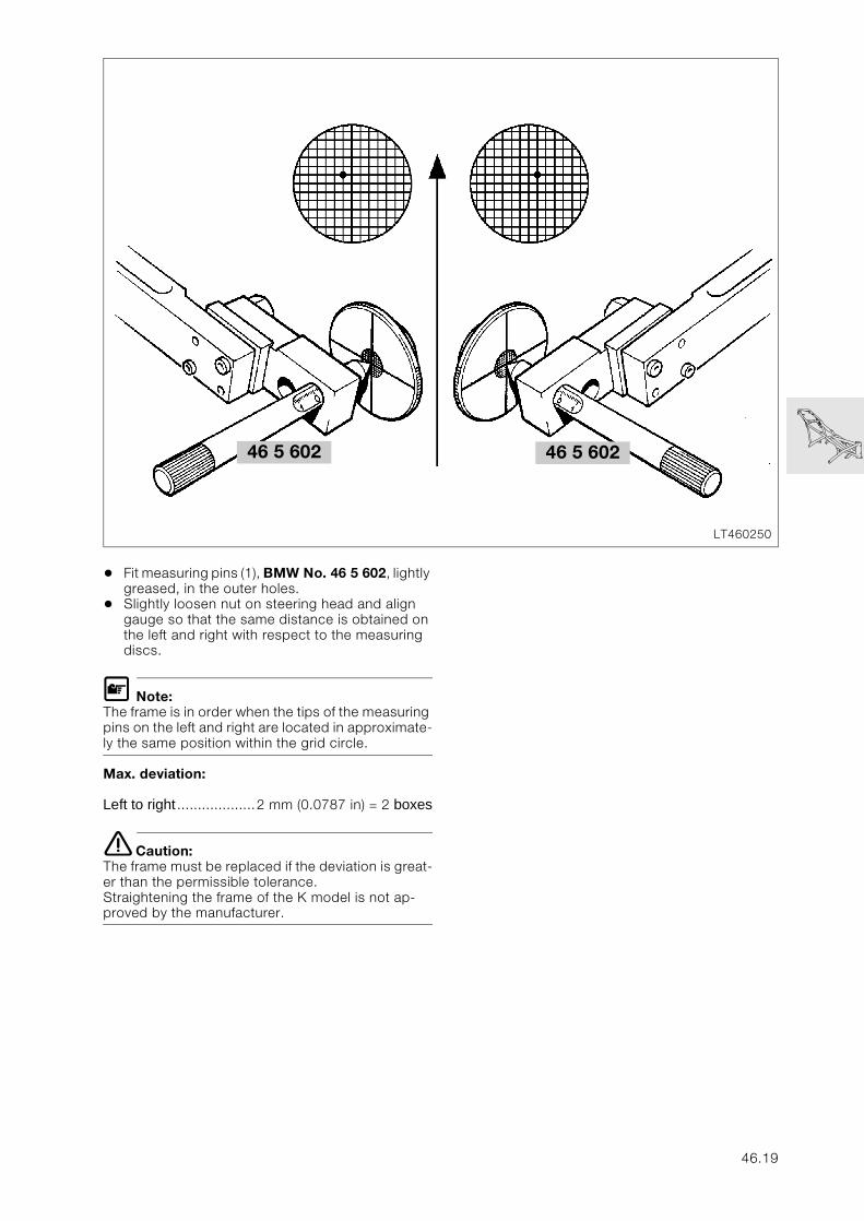
• Fit measuring pins (1), BMW No. 46 5 602, lightly greased, in the outer holes.
• Slightly loosen nut on steering head and align gauge so that the same distance is obtained on the left and right with respect to the measuring discs.
L Note:The frame is in order when the tips of the measuring pins on the left and right are located in approximate-ly the same position within the grid circle.
Max. deviation:
Left to right ...................2 mm (0.0787 in) = 2 boxes
e Caution:The frame must be replaced if the deviation is great-er than the permissible tolerance.Straightening the frame of the K model is not ap-proved by the manufacturer.
LT460250
46 5 602 46 5 602
46.19
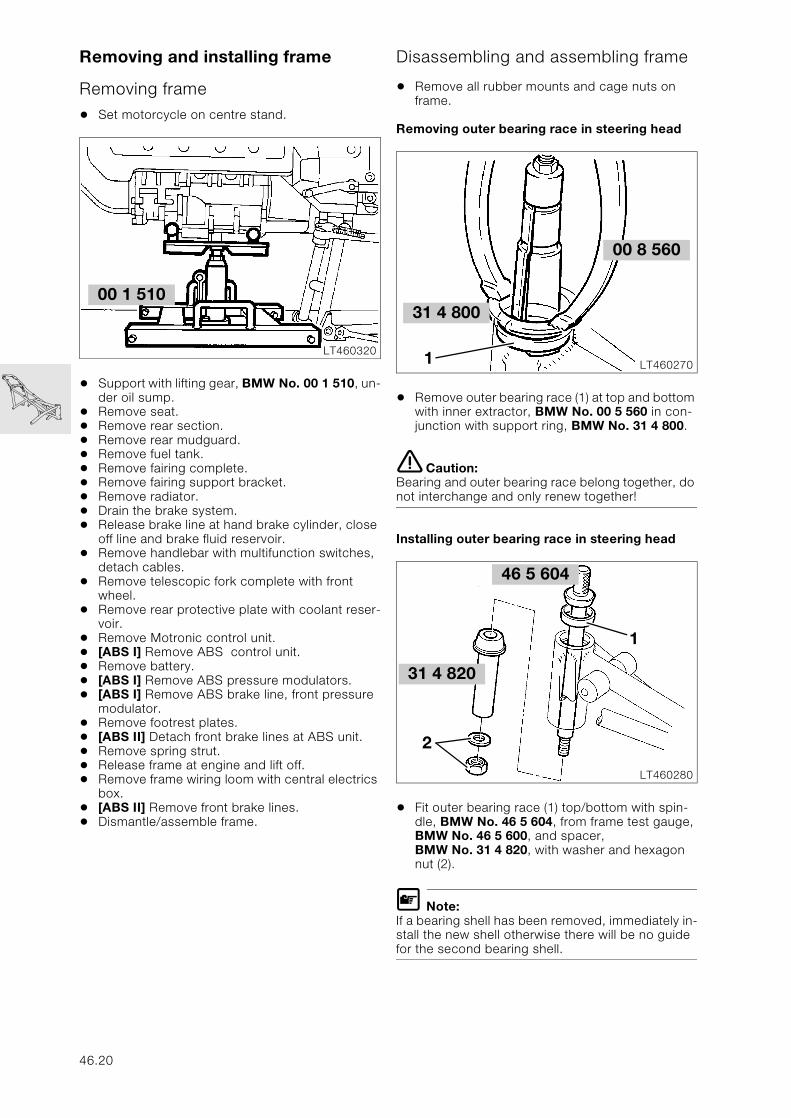
Removing and installing frame
Removing frame
• Set motorcycle on centre stand.
• Support with lifting gear, BMW No. 00 1 510, un-der oil sump.
• Remove seat.• Remove rear section.• Remove rear mudguard.• Remove fuel tank.• Remove fairing complete.• Remove fairing support bracket.• Remove radiator.• Drain the brake system.• Release brake line at hand brake cylinder, close
off line and brake fluid reservoir.• Remove handlebar with multifunction switches,
detach cables.• Remove telescopic fork complete with front
wheel.• Remove rear protective plate with coolant reser-
voir.• Remove Motronic control unit.• [ABS I] Remove ABS control unit.• Remove battery.• [ABS I] Remove ABS pressure modulators.• [ABS I] Remove ABS brake line, front pressure
modulator.• Remove footrest plates.• [ABS II] Detach front brake lines at ABS unit.• Remove spring strut.• Release frame at engine and lift off.• Remove frame wiring loom with central electrics
box.• [ABS II] Remove front brake lines.• Dismantle/assemble frame.
Disassembling and assembling frame
• Remove all rubber mounts and cage nuts on frame.
Removing outer bearing race in steering head
• Remove outer bearing race (1) at top and bottom with inner extractor, BMW No. 00 5 560 in con-junction with support ring, BMW No. 31 4 800.
e Caution:Bearing and outer bearing race belong together, do not interchange and only renew together!
Installing outer bearing race in steering head
• Fit outer bearing race (1) top/bottom with spin-dle, BMW No. 46 5 604, from frame test gauge, BMW No. 46 5 600, and spacer, BMW No. 31 4 820, with washer and hexagon nut (2).
L Note:If a bearing shell has been removed, immediately in-stall the new shell otherwise there will be no guide for the second bearing shell.
00 1 510
LT460320
00 8 560
LT4602701
31 4 800
46 5 604
LT460280
31 4 820
2
1
46.20
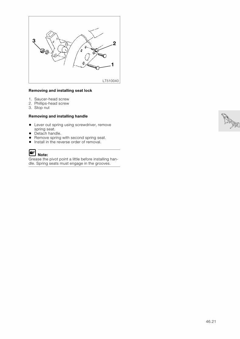
Removing and installing seat lock
1. Saucer-head screw2. Phillips-head screw3. Stop nut
Removing and installing handle
• Lever out spring using screwdriver, remove spring seat.
• Detach handle.• Remove spring with second spring seat.• Install in the reverse order of removal.
L Note:Grease the pivot point a little before installing han-dle. Spring seats must engage in the grooves.
LT510040
2
1
3
46.21
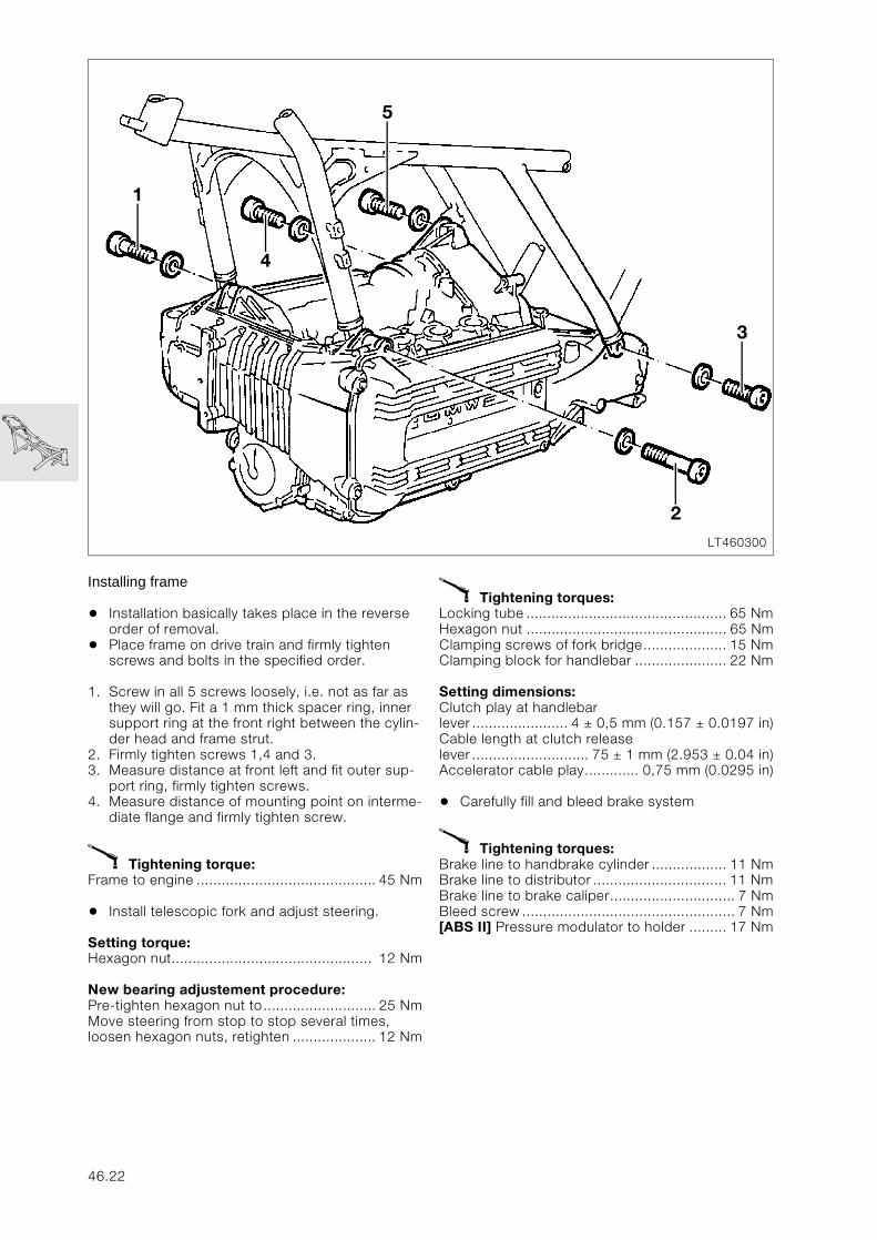
Installing frame
• Installation basically takes place in the reverse order of removal.
• Place frame on drive train and firmly tighten screws and bolts in the specified order.
1. Screw in all 5 screws loosely, i.e. not as far as they will go. Fit a 1 mm thick spacer ring, inner support ring at the front right between the cylin-der head and frame strut.
2. Firmly tighten screws 1,4 and 3.3. Measure distance at front left and fit outer sup-
port ring, firmly tighten screws.4. Measure distance of mounting point on interme-
diate flange and firmly tighten screw.
X Tightening torque:Frame to engine ........................................... 45 Nm
• Install telescopic fork and adjust steering.
Setting torque:Hexagon nut................................................ 12 Nm
New bearing adjustement procedure:Pre-tighten hexagon nut to........................... 25 NmMove steering from stop to stop several times, loosen hexagon nuts, retighten .................... 12 Nm
X Tightening torques:Locking tube ................................................ 65 NmHexagon nut ................................................ 65 NmClamping screws of fork bridge.................... 15 NmClamping block for handlebar ...................... 22 Nm
Setting dimensions:Clutch play at handlebar lever ....................... 4 ± 0,5 mm (0.157 ± 0.0197 in)Cable length at clutch release lever ............................ 75 ± 1 mm (2.953 ± 0.04 in)Accelerator cable play............. 0,75 mm (0.0295 in)
• Carefully fill and bleed brake system
X Tightening torques:Brake line to handbrake cylinder .................. 11 NmBrake line to distributor ................................ 11 NmBrake line to brake caliper.............................. 7 NmBleed screw ................................................... 7 Nm[ABS II] Pressure modulator to holder ......... 17 Nm
LT460300
2
3
4
1
5
46.22
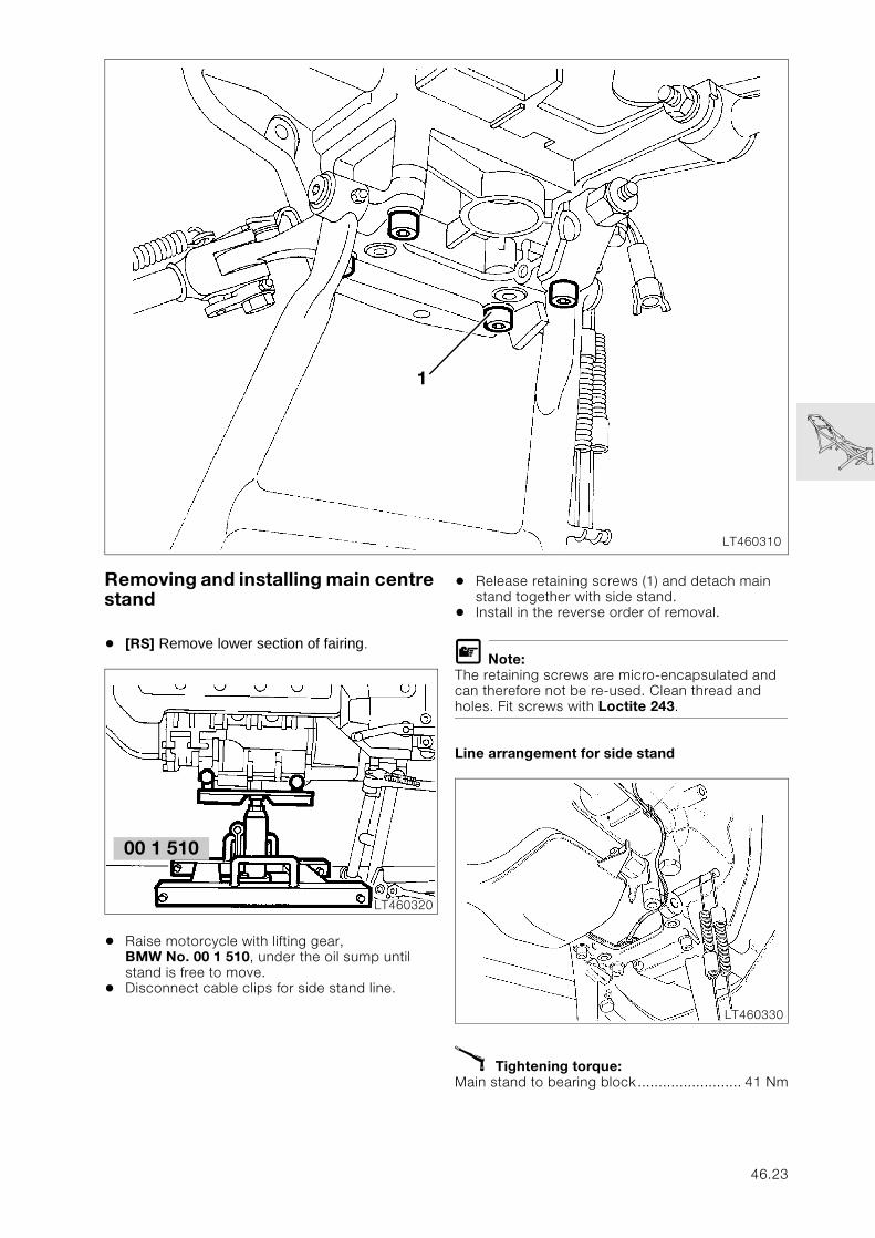
Removing and installing main centre stand
• [RS] Remove lower section of fairing.
• Raise motorcycle with lifting gear, BMW No. 00 1 510, under the oil sump until stand is free to move.
• Disconnect cable clips for side stand line.
• Release retaining screws (1) and detach main stand together with side stand.
• Install in the reverse order of removal.
L Note:The retaining screws are micro-encapsulated and can therefore not be re-used. Clean thread and holes. Fit screws with Loctite 243.
Line arrangement for side stand
X Tightening torque:Main stand to bearing block......................... 41 Nm
LT460310
1
00 1 510
LT460320
LT460330
46.23
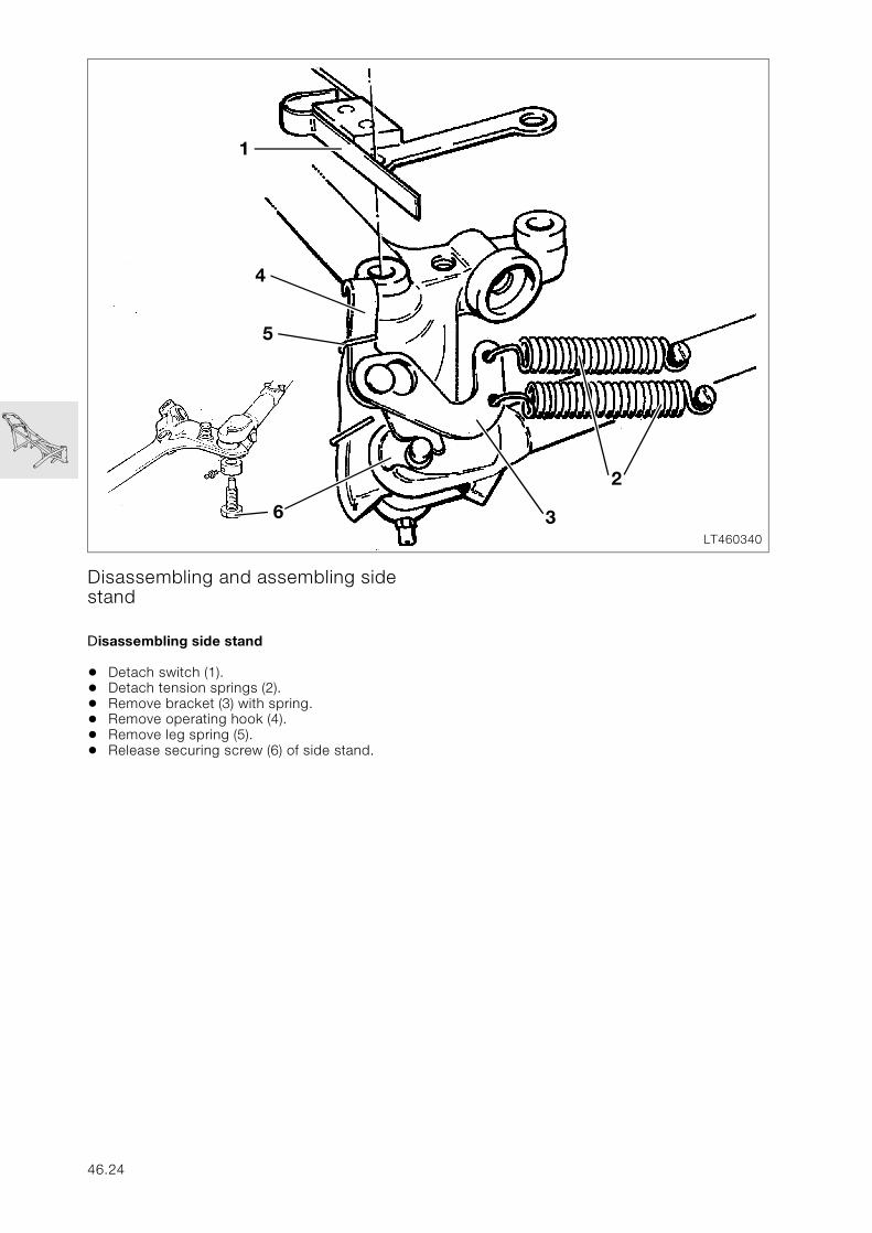
Disassembling and assembling side stand
Disassembling side stand
• Detach switch (1).• Detach tension springs (2).• Remove bracket (3) with spring.• Remove operating hook (4).• Remove leg spring (5).• Release securing screw (6) of side stand.
LT460340
1
2
6
4
5
3
46.24
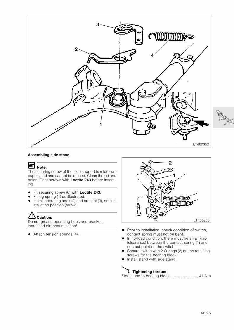
Assembling side stand
L Note:The securing screw of the side support is micro-en-capsulated and cannot be reused. Clean thread and holes. Coat screws with Loctite 243 before insert-ing.
• Fit securing screw (6) with Loctite 243.• Fit leg spring (1) as illustrated.• Install operating hook (2) and bracket (3), note in-
stallation position (arrow).
e Caution:Do not grease operating hook and bracket, increased dirt accumulation!
• Attach tension springs (4).• Prior to installation, check condition of switch,
contact spring must not be bent.• In no-load condition, there must be an air gap
(clearance) between the contact spring (1) and contact point on the switch.
• Secure switch with 2 O-rings (2) on the retaining screws for the bearing block.
• Install stand with side stand.
X Tightening torque:Side stand to bearing block ......................... 41 Nm
LT460350
24
3
1
LT460360
2
1
46.25
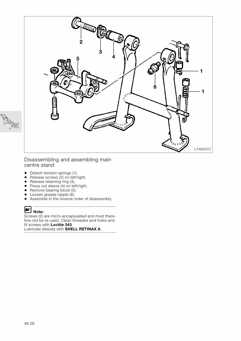
Disassembling and assembling main centre stand
• Detach tension springs (1).• Release screws (2) on left/right.• Release retaining ring (3).• Press out sleeve (4) on left/right.• Remove bearing block (5).• Loosen grease nipple (6).• Assemble in the reverse order of disassembly.
L Note:Screws (2) are micro-encapsulated and must there-fore not be re-used. Clean threades and holes and fit screws with Loctite 243.Lubricate sleeves with SHELL RETINAX A.
LT460370
1
6
5
1
2
34
46.26
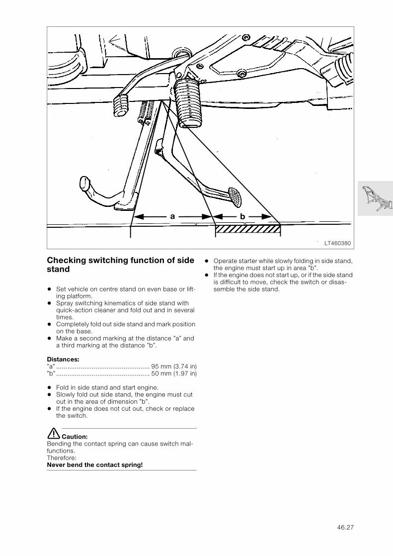
Checking switching function of side stand
• Set vehicle on centre stand on even base or lift-ing platform.
• Spray switching kinematics of side stand with quick-action cleaner and fold out and in several times.
• Completely fold out side stand and mark position on the base.
• Make a second marking at the distance ”a” and a third marking at the distance ”b”.
Distances:”a” .................................................. 95 mm (3.74 in)”b” .................................................. 50 mm (1.97 in)
• Fold in side stand and start engine.• Slowly fold out side stand, the engine must cut
out in the area of dimension ”b”.• If the engine does not cut out, check or replace
the switch.
e Caution:Bending the contact spring can cause switch mal-functions.Therefore:Never bend the contact spring!
• Operate starter while slowly folding in side stand, the engine must start up in area ”b”.
• If the engine does not start up, or if the side stand is difficult to move, check the switch or disas-semble the side stand.
LT460380
a b
46.27

46.28
51
Contents Page
51 Equipment
Removing and installing ignition switch/steering lock ...........................................3
Removing and installing lock cylinder for fuel tank ..................................................4
Removing lock cylinder ................................................................................................................4
Installing locking cylinder ............................................................................................................4
Removing lock cylinder with broken key ..............................................................................4
Removing and installing dualseat lock ............................................................................5
51.1

51.2
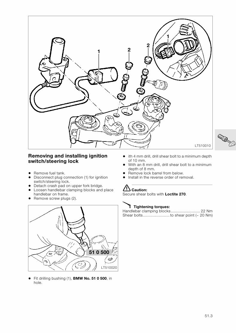
51
Removing and installing ignition switch/steering lock
• Remove fuel tank.• Disconnect plug connection (1) for ignition
switch/steering lock.• Detach crash pad on upper fork bridge.• Loosen handlebar clamping blocks and place
handlebar on frame.• Remove screw plugs (2).
• Fit drilling bushing (1), BMW No. 51 0 500, in hole.
• ith 4 mm drill, drill shear bolt to a minimum depth of 10 mm.
• With an 8 mm drill, drill shear bolt to a minimum depth of 8 mm.
• Remove lock barrel from below.• Install in the reverse order of removal.
e Caution:Secure shear bolts with Loctite 270.
X Tightening torques:Handlebar clamping blocks.......................... 22 NmShear bolts........................ to shear point (~ 20 Nm)
LT510010
1
221
51 0 500
LT510020
51.3
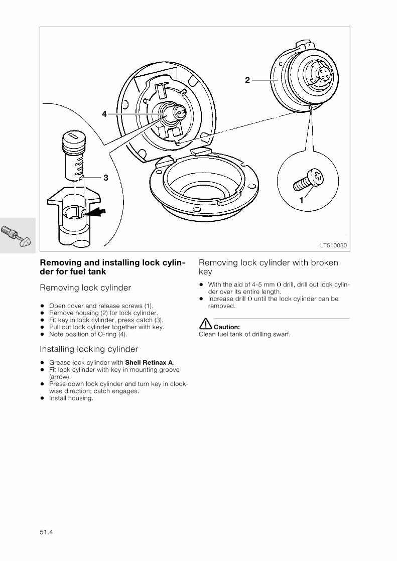
Removing and installing lock cylin-der for fuel tank
Removing lock cylinder
• Open cover and release screws (1).• Remove housing (2) for lock cylinder.• Fit key in lock cylinder, press catch (3).• Pull out lock cylinder together with key.• Note position of O-ring (4).
Installing locking cylinder
• Grease lock cylinder with Shell Retinax A.• Fit lock cylinder with key in mounting groove
(arrow).• Press down lock cylinder and turn key in clock-
wise direction; catch engages.• Install housing.
Removing lock cylinder with broken key
• With the aid of 4-5 mm O drill, drill out lock cylin-der over its entire length.
• Increase drill O until the lock cylinder can be removed.
e Caution:Clean fuel tank of drilling swarf.
LT510030
2
3
4
1
51.4
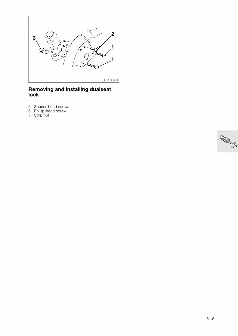
Removing and installing dualseat lock
5. Saucer-head screw6. Phillip-head screw7. Stop nut
LT510040
2
1
1
3
51.5

51.6
61
Contents Page
61 General electrical equipment
Technical Data ............................................................................................................................... 3
Removing and installing Motronic control unit ...........................................................5
[ABS I] Removing and installing control unit ................................................................6
[ABS II] Removing and installing control unit ...............................................................6
Removing and installing battery ..........................................................................................7
Relay locations (central electrical unit) ............................................................................8
Locations and connections, ABS wiring loom .............................................................9
Locations, frame wiring loom ..............................................................................................10
View from left ..................................................................................................................................10
Wiring arrangement, fairing bracket, [LT] ...........................................................................10
View from right ...............................................................................................................................11
Wiring arrangement fairing bracket, [RS] ............................................................................11
61.1
61.2

61
Technical Data K 1100 LT K 1100 RS
Battery Ah 19
61.3

61.4
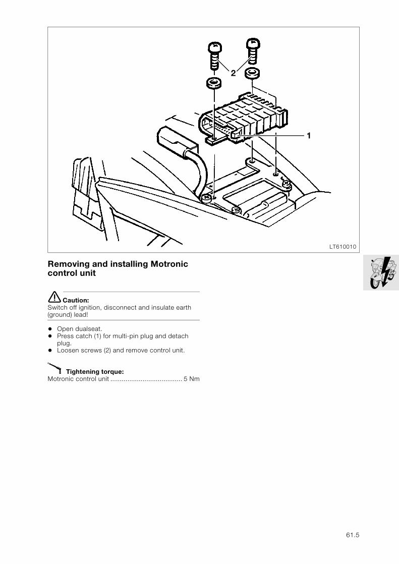
Removing and installing Motronic control unit
e Caution:Switch off ignition, disconnect and insulate earth (ground) lead!
• Open dualseat.• Press catch (1) for multi-pin plug and detach
plug.• Loosen screws (2) and remove control unit.
X Tightening torque:Motronic control unit ...................................... 5 Nm
LT610010
2
1
61.5
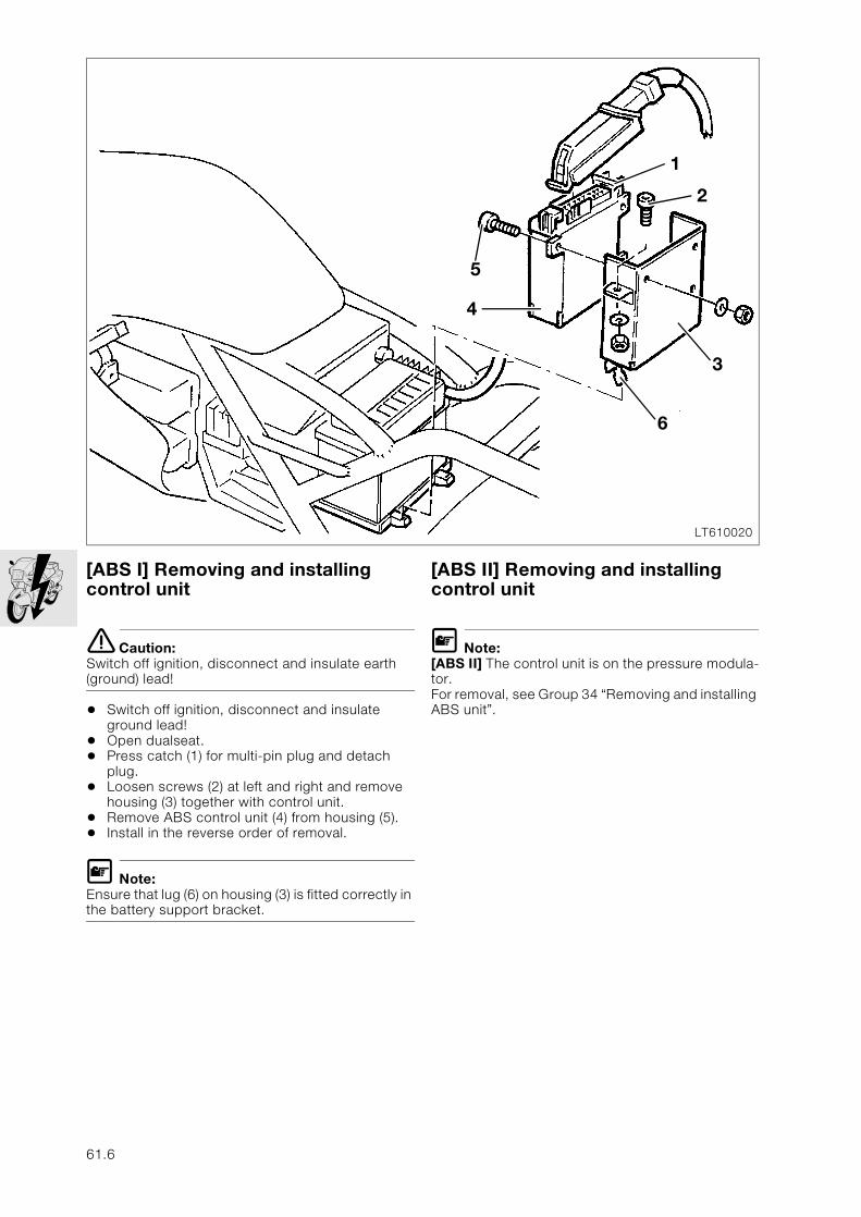
[ABS I] Removing and installing control unit
e Caution:Switch off ignition, disconnect and insulate earth (ground) lead!
• Switch off ignition, disconnect and insulate ground lead!
• Open dualseat.• Press catch (1) for multi-pin plug and detach
plug.• Loosen screws (2) at left and right and remove
housing (3) together with control unit.• Remove ABS control unit (4) from housing (5).• Install in the reverse order of removal.
L Note:Ensure that lug (6) on housing (3) is fitted correctly in the battery support bracket.
[ABS II] Removing and installing control unit
L Note:[ABS II] The control unit is on the pressure modula-tor.For removal, see Group 34 “Removing and installing ABS unit”.
LT610020
4
3
1
5
2
6
61.6
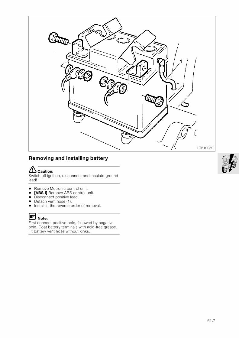
Removing and installing battery
e Caution:Switch off ignition, disconnect and insulate ground lead!
• Remove Motronic control unit.• [ABS I] Remove ABS control unit.• Disconnect positive lead.• Detach vent hose (1).• Install in the reverse order of removal.
L Note:First connect positive pole, followed by negative pole. Coat battery terminals with acid-free grease. Fit battery vent hose without kinks.
LT610030
1
61.7
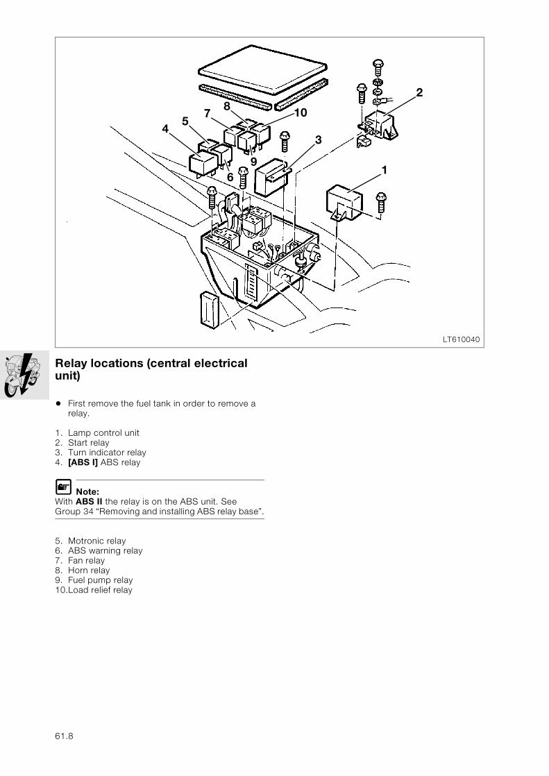
Relay locations (central electrical unit)
• First remove the fuel tank in order to remove a relay.
1. Lamp control unit2. Start relay3. Turn indicator relay4. [ABS I] ABS relay
L Note:With ABS II the relay is on the ABS unit. See Group 34 “Removing and installing ABS relay base”.
5. Motronic relay6. ABS warning relay7. Fan relay8. Horn relay9. Fuel pump relay10.Load relief relay
LT610040
69
10
3
1
2
57
4
8
61.8
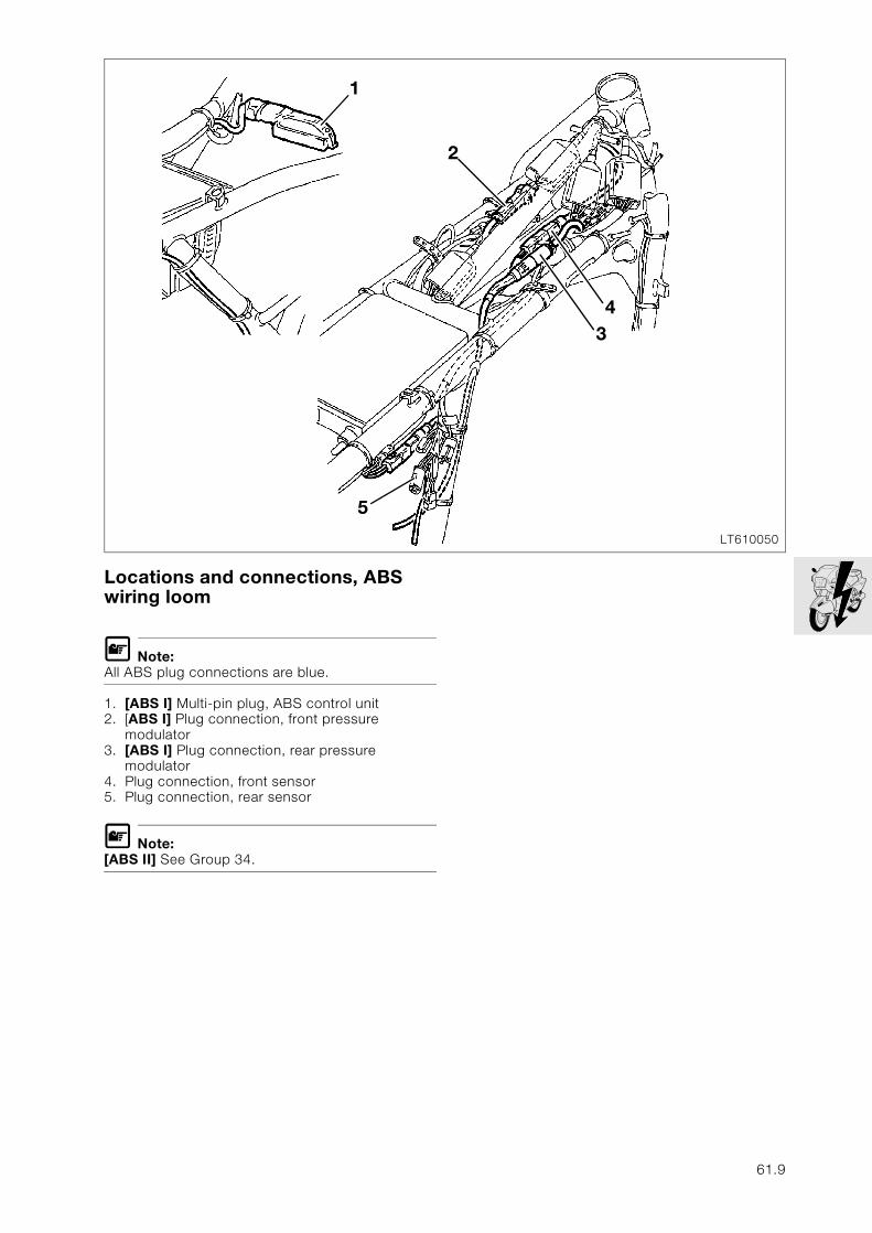
Locations and connections, ABS wiring loom
L Note:All ABS plug connections are blue.
1. [ABS I] Multi-pin plug, ABS control unit2. [ABS I] Plug connection, front pressure
modulator3. [ABS I] Plug connection, rear pressure
modulator4. Plug connection, front sensor5. Plug connection, rear sensor
L Note:[ABS II] See Group 34.
LT610050
5
1
2
34
61.9
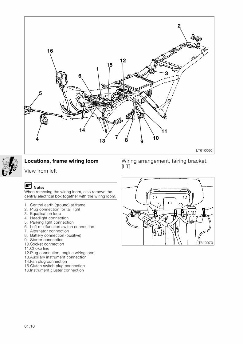
Locations, frame wiring loom
View from left
L Note:When removing the wiring loom, also remove the central electrical box together with the wiring loom.
1. Central earth (ground) at frame2. Plug connection for tail light3. Equalisation loop4. Headlight connection5. Parking light connection6. Left multfunction switch connection7. Alternator connection8. Battery connection (positive)9. Starter connection10.Socket connection11.Choke line12.Plug connection, engine wiring loom13.Auxiliary instrument connection14.Fan plug connection15.Clutch switch plug connection16.Instrument cluster connection
Wiring arrangement, fairing bracket, [LT]
LT610060
8
1512
3
4
147
13
61
2
5
910
11
16
LT610070
61.10
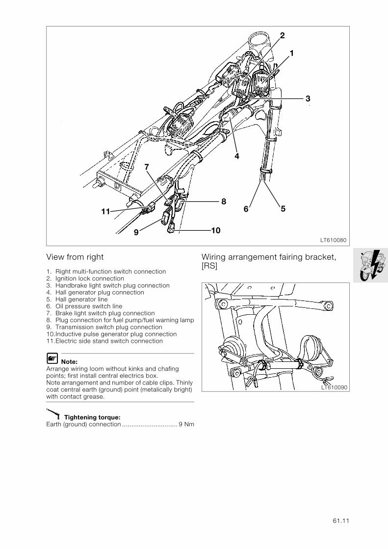
View from right
1. Right multi-function switch connection2. Ignition lock connection3. Handbrake light switch plug connection4. Hall generator plug connection5. Hall generator line6. Oil pressure switch line7. Brake light switch plug connection 8. Plug connection for fuel pump/fuel warning lamp9. Transmission switch plug connection10.Inductive pulse generator plug connection11.Electric side stand switch connection
L Note:Arrange wiring loom without kinks and chafing points; first install central electrics box.Note arrangement and number of cable clips. Thinly coat central earth (ground) point (metalically bright) with contact grease.
X Tightening torque:Earth (ground) connection .............................. 9 Nm
Wiring arrangement fairing bracket, [RS]
LT610080
11 6
3
47
2
1
58
109
LT610090
61.11

61.12
62
Contents Page
62 Instruments
Technical Data ............................................................................................................................... 3
Removing and installing instrument cluster ..................................................................5
[LT] .........................................................................................................................................................5
[RS] ........................................................................................................................................................6
Disassembling and assembling instrument cluster .........................................................7Removing and installing indicator lamp ...............................................................................................7Removing and installing p.c. board .....................................................................................................8Removing and installing quartz clock ..................................................................................................8Removing and installing frame for indicator lamps ...............................................................................8Removing and installing p.c. board for fuel gauge ...............................................................................8Removing and installing revolution counter .........................................................................................9Removing and installing speedometer .................................................................................................9Removing and installing p.c. board for gear indicator ........................................................................10
62.1

62.2
62
Technical Data K 1100 LT K 1100 RS
Instrument cluster
Turn signal indicator lamps 12 V/4 W T 8/4
Other indicator lamps, instrument lights 12 V/3 W 10/3
62.3

62.4
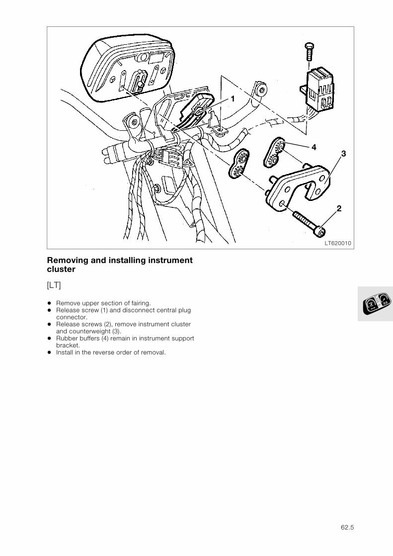
Removing and installing instrument cluster
[LT]
• Remove upper section of fairing.• Release screw (1) and disconnect central plug
connector.• Release screws (2), remove instrument cluster
and counterweight (3).• Rubber buffers (4) remain in instrument support
bracket.• Install in the reverse order of removal.
LT620010
43
2
1
62.5
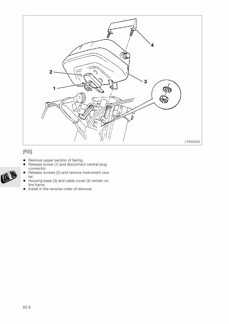
[RS]
• Remove upper section of fairing.• Release screw (1) and disconnect central plug
connector.• Release screws (2) and remove instrument clus-
ter.• Housing base (3) and cable cover (4) remain on
the frame.• Install in the reverse order of removal.
LT620020
1
4
3
2
62.6
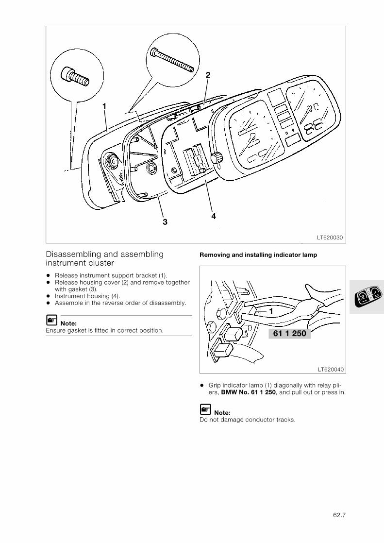
Disassembling and assembling instrument cluster
• Release instrument support bracket (1).• Release housing cover (2) and remove together
with gasket (3).• Instrument housing (4).• Assemble in the reverse order of disassembly.
L Note:Ensure gasket is fitted in correct position.
Removing and installing indicator lamp
• Grip indicator lamp (1) diagonally with relay pli-ers, BMW No. 61 1 250, and pull out or press in.
L Note:Do not damage conductor tracks.
LT620030
3
1
4
2
61 1 250
LT620040
1
62.7
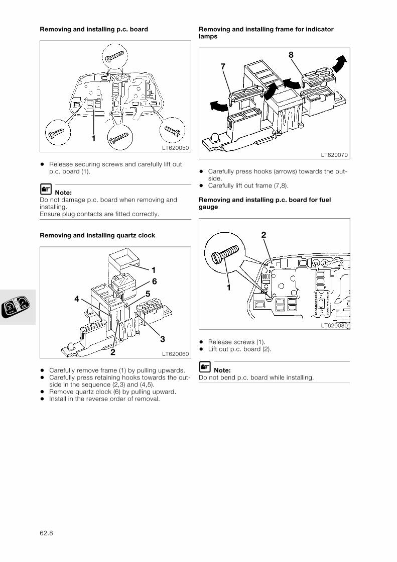
Removing and installing p.c. board
• Release securing screws and carefully lift out p.c. board (1).
L Note:Do not damage p.c. board when removing and installing.Ensure plug contacts are fitted correctly.
Removing and installing quartz clock
• Carefully remove frame (1) by pulling upwards.• Carefully press retaining hooks towards the out-
side in the sequence (2,3) and (4,5).• Remove quartz clock (6) by pulling upward.• Install in the reverse order of removal.
Removing and installing frame for indicator lamps
• Carefully press hooks (arrows) towards the out-side.
• Carefully lift out frame (7,8).
Removing and installing p.c. board for fuel gauge
• Release screws (1).• Lift out p.c. board (2).
L Note:Do not bend p.c. board while installing.
LT620050
1
LT620060
1
2
6
4
3
5
LT620070
78
LT620080
1
2
62.8
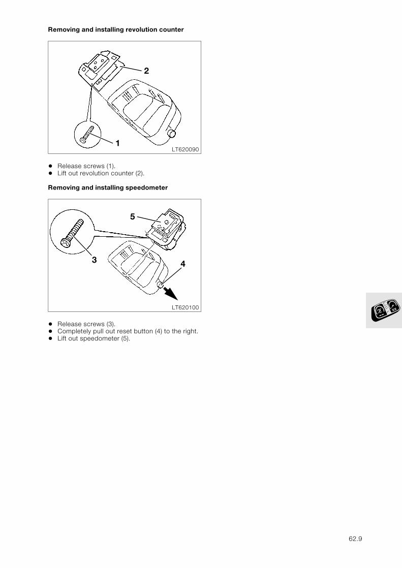
Removing and installing revolution counter
• Release screws (1).• Lift out revolution counter (2).
Removing and installing speedometer
• Release screws (3).• Completely pull out reset button (4) to the right.• Lift out speedometer (5).
LT6200901
2
LT620100
5
43
62.9
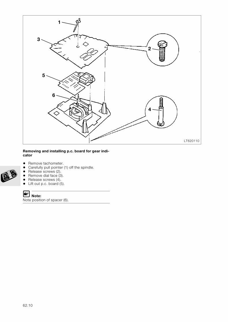
Removing and installing p.c. board for gear indi-cator
• Remove tachometer.• Carefully pull pointer (1) off the spindle.• Release screws (2).• Remove dial face (3).• Release screws (4).• Lift out p.c. board (5).
L Note:Note position of spacer (6).
LT620110
2
4
1
3
5
6
62.10
63
Contents Page
63 Lights
Technical Data ............................................................................................................................... 3
Disassembling and assembling headlights ....................................................................5
Adjusting headlights ...................................................................................................................6
63.1

63.2
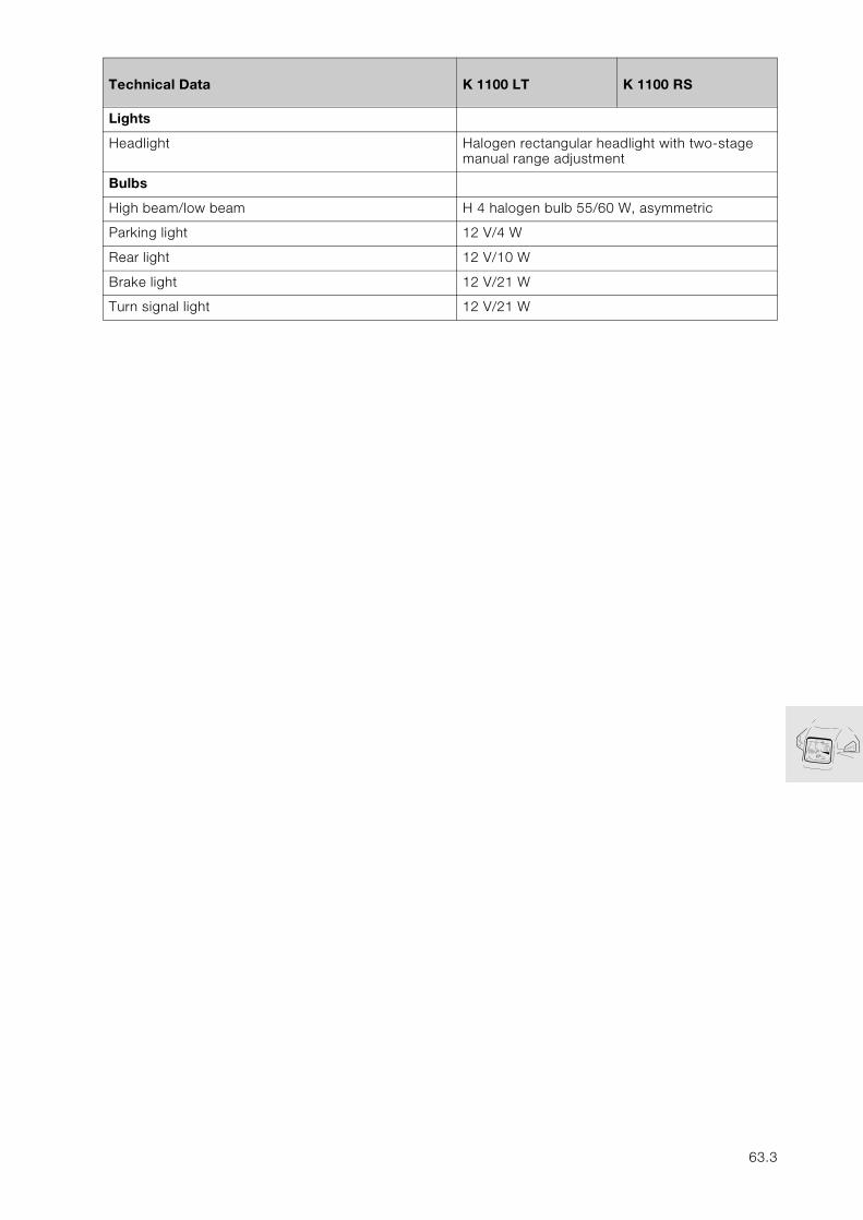
63
Technical Data K 1100 LT K 1100 RS
Lights
Headlight Halogen rectangular headlight with two-stage manual range adjustment
Bulbs
High beam/low beam H 4 halogen bulb 55/60 W, asymmetric
Parking light 12 V/4 W
Rear light 12 V/10 W
Brake light 12 V/21 W
Turn signal light 12 V/21 W
63.3

63.4
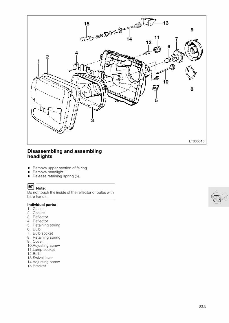
Disassembling and assembling headlights
• Remove upper section of fairing.• Remove headlight.• Release retaining spring (5).
L Note:Do not touch the inside of the reflector or bulbs with bare hands.
Individual parts:1. Glass2. Gasket3. Reflector4. Reflector5. Retaining spring6. Bulb7. Bulb socket8. Retaining spring9. Cover10.Adjusting screw11.Lamp socket12.Bulb13.Swivel lever14.Adjusting screw15.Bracket
LT630010
1315
12
4
1211
6
7
9
3
5
10
8
14
63.5
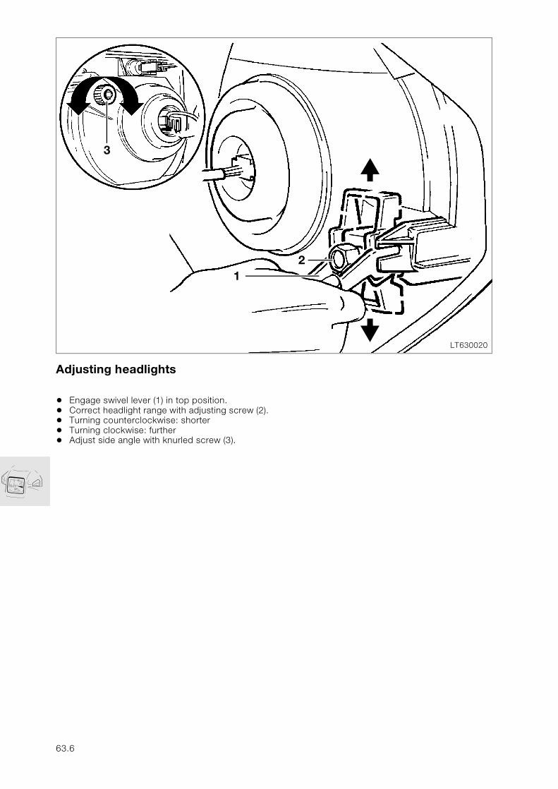
Adjusting headlights
• Engage swivel lever (1) in top position.• Correct headlight range with adjusting screw (2).• Turning counterclockwise: shorter• Turning clockwise: further• Adjust side angle with knurled screw (3).
LT630020
2
3
1
63.6
Recommended